

Page 1

LD Cart Transporter Mobile Robot
User’s Guide
I612-E-02
Page 2

Copyright Notice
The information contained herein is the property of Omron Adept Technologies, Inc., and shall
not be reproduced in whole or in part without prior written approval of Omron Adept Technologies, Inc. The information herein is subject to change without notice and should not be construed as a commitment by Omron Adept Technologies, Inc. The documentation is periodically
reviewed and revised.
Omron Adept Technologies, Inc., assumes no responsibility for any errors or omissions in the
documentation. Critical evaluation of the documentation by the user is welcomed. Your comments assist us in preparation of future documentation. Please submit your
comments to: [email protected].
Copyright 2016, 2017 by Omron Adept Technologies, Inc. All rights reserved.
Any trademarks from other companies used in this publication are the property of those
respective companies.
MPEG Layer-3 audio coding technology licensed from Fraunhofer IIS and Thomson.
Copyright 2012 CEPSTRAL LLC http://www.cepstral.com This product may contain copyright
material licensed from CEPSTRAL LLC, all right reserved.
This manual was originally written in English.
Created in the United States of America
LD Cart Transporter User's Guide, 14766-000 Rev B
Page 2 of 190
Page 3

Table of Contents
Chapter 1: Introduction 9
Definitions 9
1.1 Product Description
LD Cart Transporter 11
Cart 13
Coupling 14
Optional Components 14
User-Supplied Components / System Requirements 15
1.2 Software Overview
Mobile Robot Software Suite 15
SetNetGo 16
1.3 How Can I Get Help?
Related Manuals 17
Support 17
Including a DebugInfo File 17
Chapter 2: Safety 21
15
17
9
2.1 Dangers, Warnings, Cautions, and Precautions
2.2 What to Do in an Emergency /Abnormal Situation
Releasing the Brakes 21
Releasing an E-Stop 22
2.3 User's Responsibilities
General Hazards 22
Falling Hazards 23
Electrical Hazards 23
Pinch Hazards 24
Magnetic Field Hazards 24
Qualification of Personnel 25
Payload Movement and Transfer 26
Configurable Warning Buzzer 26
Multi-Vehicle Avoidance 26
Traffic Control 27
Passing Lanes 27
2.4 Environment
General Environmental Conditions 27
Public Access 27
Clearance 27
Obstacles 28
2.5 Intended Use
Non-Intended Use 28
Robot Modifications 29
21
21
22
27
28
LD Cart Transporter User's Guide, 14766-000 Rev B
Page 3 of 190
Page 4

Table of Contents
2.6 Battery Safety
2.7 Additional Safety Information
Accidental Cart Separation 29
Mobile Robot LDSafety Guide 29
29
29
Chapter 3: Setup 31
Overview 31
Tasks 31
3.1 Transport and Storage
LD Cart Transporter 32
Battery 32
Standalone Cart 32
3.2 Before Unpacking
3.3 Unpacking
Battery 33
LD Cart Transporter 35
Repacking for Relocation 38
3.4 Setting Up an LD Cart Transporter
Mounting the Side Lasers 38
Rolling the LD Cart Transporter off of the Crate Base 42
Installing the Battery 45
Installing the Docking Station 50
3.5 Installing the Cart Brake Release
Installation 56
Adjustment 59
32
33
33
38
55
Chapter 4: Configuration 61
4.1 Settings and Configuration
Maintenance Ethernet Connection 61
Setting Up Wireless Ethernet 62
4.2 Mapping
Setting Up Cart-Parking Goals 65
Marking Cart-Parking Goals on Floor 65
4.3 Configuring a Touchscreen
Touchscreen Ethernet Setup 65
Operating Modes 66
Localization Goals 68
Screen Logo 69
Screensaver 70
Display Language 71
Contact Information 72
4.4 Acceleration, Deceleration, and Rotation Limits
4.5 Supplemental Information
Laser Setup 73
61
64
65
72
73
LD Cart Transporter User's Guide, 14766-000 Rev B
Page 4 of 190
Page 5

Table of Contents
Chapter 5: Payloads 75
5.1 Safety
Drive Warning Light 75
Turn Warning Lights 75
5.2 Considerations
Dimensions 75
Pinch Hazard 75
Weight 76
Center of Gravity 76
5.3 Payload-Related Tradeoffs
75
75
81
Chapter 6: Connectivity 83
6.1 Required Connections
6.2 LD Cart Transporter Connections
Core 84
Cart-Specific PCA 85
6.3 Standard Platform Connections
Robot Core Front, Upper 90
Robot Core Rear, Upper 97
Internal Robot Core Connections 104
Core Internal Data Pinouts 105
Robot Core Internal Power Pinouts 107
83
83
89
Chapter 7: Operator Interface 109
7.1 Touchscreen
Touchscreen Initialization 109
Touchscreen Configuration 110
Screen Top Bar 110
Left Screen Pane 110
Right Screen Pane 112
Center Pane 116
Relocalization 116
Choose Dropoff Mode 116
Patrol Route Mode 119
7.2 Operator Panel
E-Stop Button 120
ON Button 121
OFF Button 121
Brake-release (BRAKE)Button 121
Keyswitch 121
LATCH Button 121
UNLATCH Button 121
7.3 Other Controls and Indicators
Light Discs and Beacon 121
Robot Core Indicators 126
109
120
121
LD Cart Transporter User's Guide, 14766-000 Rev B
Page 5 of 190
Page 6

Table of Contents
Battery and Docking Station 127
Chapter 8: Operation 129
8.1 Operating Environment
Intended Use 129
Clearance 129
Obstacles 129
Environment and Floor 130
Getting Stuck 130
8.2 Typical Operation
8.3 Power and Charging
Battery Indicators and Controls 132
Docking Station 133
Manually Charging the Battery 135
Balancing the Battery 136
8.4 Startup
Procedure 137
Joystick 137
8.5 Working with Carts
Goals 138
Operation 138
Cart-Locating 138
Cart Brakes 139
129
131
132
137
138
Chapter 9: Options 141
Enterprise Manager 1100 141
MobilePlanner Software (licensed) 141
Joystick 141
Spare Battery 141
Spare Carts 141
Call Buttons/Door Boxes 141
Acuity Localization 142
High-Accuracy Positioning System 142
Chapter 10: Maintenance 143
10.1 Safety Aspects While Performing Maintenance
Electrical Hazards 144
Pinch Hazard 145
Magnetic Field Hazards 145
10.2 Lifting the Platform Safely
Front Lifting Points 145
Rear Lifting Area 146
10.3 Safety Inspection
Warning Devices 147
Warning Labels 147
144
145
147
LD Cart Transporter User's Guide, 14766-000 Rev B
Page 6 of 190
Page 7

Table of Contents
Informative Labels 149
10.4 Cleaning
Work Area Maintenance 150
LD Cart Transporter and Cart 151
Tires 151
Casters 151
Axles 151
Lasers 152
Docking Station Contacts 152
10.5 Accessing the Payload Bay
Removing Latching Mechanism Cover 152
Removing Top Plate 153
Installing Top Plate 153
Installing Latching Mechanism Cover 153
10.6 Removing and Installing LD Cart Transporter Covers
Removing Covers 154
Installing Covers 157
10.7 Replacing Periodic Parts
10.8 Replacing Non-Periodic Parts
Docking Station Roller and Bearing 160
Safety Scanning Laser 162
Obstacle Detection and Coupling Lasers 163
Rear Sonar Units 166
Sonar Controller 167
Cart Latching Mechanism 168
Light Discs 169
Wheels and Tires 170
Drive Assemblies 172
Platform Casters 173
Cart Casters 175
Cart Brake Release 178
Robot Core 179
E-Stop and Safety Laser Commissioning 181
150
152
154
159
160
Chapter 11: Technical Specifications 183
11.1 Dimension Drawings
11.2 Specifications
LD Cart Transporter Physical 184
LD Cart Transporter Performance 185
Battery Output 186
Cart 187
Docking Station 187
LD Cart Transporter User's Guide, 14766-000 Rev B
Page 7 of 190
183
184
Page 8

Page 9

Chapter 1: Introduction
This manual covers the setup, operation, and user maintenance of an LD Cart Transporter system.
The basic configuration performed using the software that comes with the system is covered.
Full details of that configuration are covered in the Mobile Robot Software Suite User's Guide.
Definitions
Platform: The most basic part of the robot. It includes the chassis, drive assemblies, suspension, wheels, battery, safety scanning laser, obstacle-avoidance lasers, sonar, an on-board
robot core with built-in gyroscope, software needed to navigate, connectors for interfacing with
and powering the Operator panel and cart coupling system, Operator panel, and the platform
covers.
LD Cart Transporter:A Platform with the HMI post (including extended arms)and the coupling plate attached, set up to transport a cart. This is also referred to as just a transporter.
Cart:A cart, on four casters, that can be attached to an LD Cart Transporter, for increasing the
transporter’s payload capacity. The cart has brakes on two casters, which can be released
either by coupling with a transporter, or by using a manual brake-release lever on the cart.
AIV (Autonomous Intelligent Vehicle):The transporter with a cart attached to it. This is the
complete mobile robot, which will transport your payload on the cart.
For the initial setup, configuration, and connections, we will refer to the platform.
For controlling or monitoring the full mobile robot, with a cart attached, we will refer to the
AIV or robot.
1.1 Product Description
The LD Cart Transporter is a general-purpose mobile robot designed for moving a detachable
cart indoors and around people. It is self-guided and self-charging, with an automated docking
station.
The transporter, which moves the cart, comes complete with the ability to know where it is
within your workspace, and to navigate safely and autonomously to any accessible destination
within that workspace, continuously and without human intervention.
The cart is intended to expand the range of payloads that can be moved by an transporter,
both in weight and size.
The LD Cart Transporter is available in two models, designed to transport carts with a total
weight up to 105 kg (231 lb)for the LD-105CT and 130 kg (287 lb) for the LD-130CT platform.
Where appropriate, differences between the models are called out. Otherwise, this manual
applies to both LD Cart Transporters.
LD Cart Transporter User's Guide, 14766-000 Rev B
Page 9 of 190
Page 10
Chapter 1: Introduction
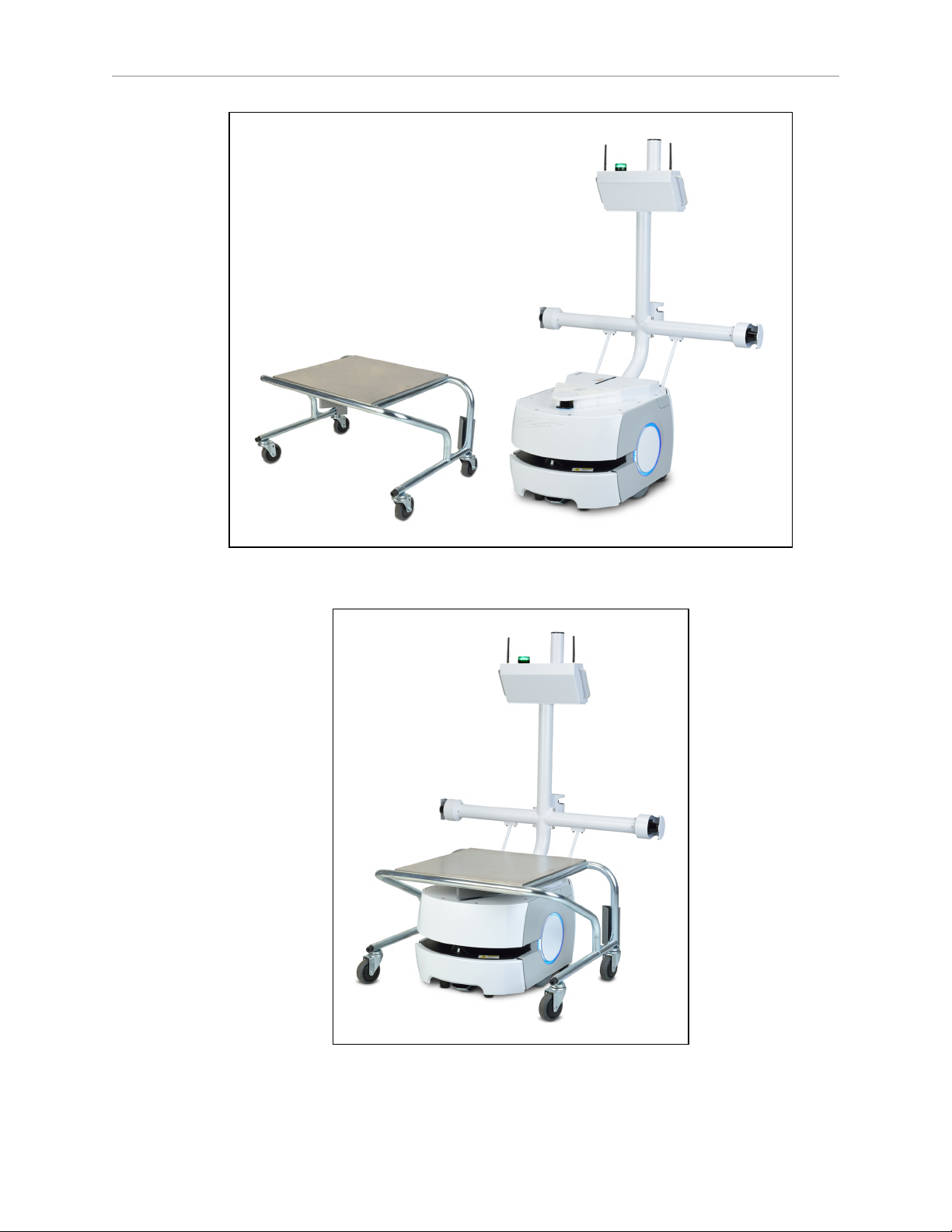
Figure 1-1. Cart and LD Cart Transporter, Separate
Figure 1-2. Cart and LD Cart Transporter, Coupled
LD Cart Transporter User's Guide, 14766-000 Rev B
Page 10 of 190
Page 11

Chapter 1: Introduction
LD-130CT
LD-105CT
Figure 1-3. LD Cart Transporter Model Labels
LD Cart Transporter
The transporter is a mobile robot platform, designed for working around people while moving
a cart. It is self-guided and self-charging, with an automated docking station. The transporter
combines hardware and mobile-robotics software to provide an intelligent, mobile platform to
transport your payload on the cart. Its primary guidance uses a safety scanning laser to navigate, comparing the laser readings to a digital map stored on the platform. The laser is backed
up by a gyroscope mounted on the internal core, and encoders and Hall sensors on each drive
wheel.
In addition to the front safety scanning laser, each transporter has two side lasers, for detecting
potential obstacles in its path, a low front laser in the bumper to detect obstacles lower than
the safety scanning laser, and a rear-facing obstacle-detection laser, to ensure that it is safe for
the transporter to back up or turn in place.
For situations that are so dynamic that laser localization becomes difficult, we offer the Acuity
Localization option, which localizes the AIV using an upward-facing camera to recognize overhead lighting patterns. This would apply to areas where objects, such as pallets or carts, are
moved so frequently that they can’t be mapped, or where they block the laser’s view of features that are mapped. This is covered in the LDPlatform Peripherals Guide.
Body and Drive
The transporter is relatively small, lightweight, and highly maneuverable. It has a strong aluminum chassis and solid construction that makes it very durable.
The platform is a two-wheel, differential-drive vehicle, with spring-loaded passive casters front
and rear, and independent drive-wheel spring-suspension for balance. Its solid, foam-filled
wheels are at the mid-line of the platform, so that the transporter can turn in place.
Safety Scanning Laser
The onboard safety scanning laser is a very precise scanning sensor. The laser provides 500
readings in a 250 degree field of view, with a typical maximum range of 15 m (49.2 ft). The
laser operates in a single plane, positioned at 203 mm (8 in.) above the floor. In most environments, the sensor will provide highly-accurate data.
LD Cart Transporter User's Guide, 14766-000 Rev B
Page 11 of 190
Page 12

Chapter 1: Introduction
Glass, mirrors, and other highly-reflective objects cannot be reliably detected by the laser. Caution must be exercised when operating the robot in areas that have these types of objects. If the
robot will need to drive in close proximity of these objects, we recommend that you use a combination of markings on the objects, such as tape or painted strips, and also use forbidden sectors in the map, so that the robot knows to plan paths safely around these objects.
Side Lasers
These two lasers are used to detect obstacles that protrude into the robot's path, but may not be
detected by the safety scanning laser.
This is needed when obstacles higher than the safety scanning laser (but low enough to be
obstacles)protrude into the robot‘s path.
Low Front Laser
This laser is mounted to the front bumper. It detects obstacles that are low and in front of the
transporter, such as an empty pallet, which might be too low for the safety scanning laser to
see.
Rear-Facing Laser
This laser gives better coverage of what’s behind the transporter than sonar alone. It is used
during both turning in place and backing up when the transporter and cart are coupled.
Coupling Laser
A laser mounted in the transporter coupling plate is used to locate a triangle on the underside
of the cart’s coupling plate. This is used by the transporter to accurately align with the cart, so
it can couple with it.
Sonar
The transporter’s two rear-facing sonar pairs are for obstacle-sensing while backing up. The
range is up to 5 m (16 ft), though the typical accurate range is only up to 2 m (10 ft). Each pair
consists of one emitter and one receiver. The sonar emitters and receivers are identical physically, but the transporter uses them differently.
Encoders and Gyroscope
Each wheel has an encoder that tells the navigation system how far the wheel has turned, and
in which direction. Each wheel also has a Hall sensor.
The robot core has a gyroscope mounted on it, to track the platform's rotation.
The combination of rotation and distance traveled are used by the platform to back up the
safety scanning laser during localization. These limit the area on the platform's map that the
platform needs to search when localizing.
What’s Included with an LD Cart Transporter
l
One fully-assembled platform
The platform includes a safety scanning laser, a low front laser, two side lasers, a rearfacing laser, and two rear-facing sonar pairs. Each pair is one transmitter and one
receiver.
LD Cart Transporter User's Guide, 14766-000 Rev B
Page 12 of 190
Page 13

Chapter 1: Introduction
l
One battery
This is shipped separately from the platform, due to air shipping regulations.
If the battery was shipped by air, it will be at less than 30% charge per IATA regulations.
l
Top plate and coupling plate
The platform top plate covers the payload bay of the platform, and supports the lower
(platform)coupling plate, which engages the cart coupling plate, attached to the cart,
and the coupling laser.
l
Robot Core, which includes an integrated computer, running Advanced Robotics Automation Management (ARAM) and a microcontroller with MARC firmware. The core is
housed inside the platform. It also runs the SetNetGo OS.
ARAM and MARC firmware and the SetNetGo OS are pre-loaded on the robot core.
l
An HMI post
This supports the two side lasers and the rear-facing laser, both for obstacle avoidance.
It also supports the Operator Panel.
l
Operator Panel
Cart
This includes a touchscreen, an E-Stop button, ON and OFF buttons, a brake-release button, and a keyswitch, which can be locked, and key removed, in either position. The
panel’s frame supports two WiFi antennas and a beacon.
There are LATCH and UNLATCH buttons below the E-Stop.
The optional Acuity Localization camera mounts on top of the Operator panel frame, on
the same plane as the antennas and beacon.
l
Automated docking station
This allows the LDPlatform to charge itself, without user intervention. It includes a
wall-mount bracket and a floor plate, for a choice of installation methods. See Installing
the Docking Station on page 50.
A manual charging cord is included, so you can charge a spare battery outside of the
platform.
l
Joystick (option)
This is used for manually controlling the robot, mostly when making a scan to be used
for generating a map.
At least one joystick is needed for each fleet of robots. Once a map is generated, the map
can be shared with multiple robots working in the same space.
The Cart is a frame mounted on four casters, designed so that it can couple with an LD Cart
Transporter. Once coupled, the cart moves with the transporter. When the transporter arrives
at the intended goal, it uncouples from the cart and leaves, while the cart remains at the goal.
Brakes automatically engage on the cart casters, preventing it from rolling in case the floor
isn’t completely level.
The cart has a manual brake-release lever, so it can be moved manually.
LD Cart Transporter User's Guide, 14766-000 Rev B
Page 13 of 190
Page 14

Chapter 1: Introduction
Coupling
The transporter can attach to a cart at a pickup goal, move the cart to a dropoff goal, and leave
it at that goal, with no human intervention.
When the cart and transporter are coupled, the transporter automatically presses a lever that
releases the cart’s brakes, so it is free to move with the transporter.
The coupling system has:
l
a motorized Latching Mechanism
l
a coupling laser
This is mounted in the coupling plate, and is used to align the transporter with the cart
when coupling.
l
LATCH and UNLATCH override buttons, on the Operator Panel
Coupling plates
Each cart has one coupling plate, and each platform has one coupling plate. The plates are
mounted so that, when the platform moves under the cart, the plates can attach to each other,
allowing the platform to move the cart. The software is aware of whether or not a cart is
attached.
l
The cart coupling plate includes a slot that can be latched with the platform coupling
plate. The cart coupling plate is passive.
l
The platform coupling plate includes a laser, for aligning the platform before coupling,
and a motorized Latching Mechanism, for latching the cart coupling plate.
Optional Components
Refer to Options on page 141 for details.
l
Acuity Navigation
For environments that are very dynamic, such that a map can’t be kept current, or
where the area is too large for the navigation laser to see, Acuity can be used to navigate using overhead light patterns seen with an upward-facing camera.
l
Enterprise Manager 1100
This system manages a fleet of robots, for multi-robot traffic coordination and job management. It includes the Enterprise Manager appliance running the Mobile Software
suite.
l
Spare battery
A spare battery can be used to minimize down-time. Swapping the battery for a fullycharged battery avoids taking the robot out of service for more than a few minutes.
l
Call/Door Boxes
These allow a robot to be requested from a remote location, or allow the robot system to
control an automated door, so the robot can pass through it.
LD Cart Transporter User's Guide, 14766-000 Rev B
Page 14 of 190
Page 15

Chapter 1: Introduction
User-Supplied Components / System Requirements
PC with Microsoft Windows
l
Ethernet (wireless preferred)
Wireless is required for a fleet (more than one robot).
l
100 megabytes of available hard-disk storage
1.2 Software Overview
Mobile Robot Software Suite
The Mobile Robot Software Suite includes all of the software used for platforms and the Enterprise Manager appliance, with the exception of the SetNetGo OS.
ARAM
The Advanced Robotics Automation Management software (ARAM) runs on the Robot Core. It
operates ranging sensors like the safety scanning laser and sonar, and performs all the highlevel, autonomous robotics functions, including obstacle avoidance, path planning, localization, navigation, and so on, culminating in motion commands to the MARC firmware.
ARAM also controls the battery and light discs, and manages digital and analog I/O, which,
along with platform power, provide for integration of application-specific sensors and effectors
that the user adds.
ARAM manages wired and wireless Ethernet communications with offboard software, for
external monitoring, development, and systems coordination, including coordination of a fleet
of robots through the optional Enterprise Manager 1100. It also manages integration with other
systems, as well as external monitoring, setup, and control with the MobilePlanner application.
®
ARAMCentral
ARAMCentral is the software that runs on the Enterprise Manager appliance. This software
and the appliance combined are referred to as the Enterprise Manager 1100.
For a fleet, the ARAMCentral software manages:
l
the map that all robots use
l
the configuration that all robots use
l
traffic control of the robots
This includes multi-robot avoidance, destination, standby, and dock control.
l
queuing of jobs for the robots
l
remote I/O, if you are using it
MobilePlanner (licensed)
In order to have your robot perform autonomous mobile activities, you need to make a map of
its operating space, and configure its operating parameters. The MobilePlanner software is
used to make this map and perform this configuration.
LD Cart Transporter User's Guide, 14766-000 Rev B
Page 15 of 190
Page 16

Chapter 1: Introduction
Refer to the separate Mobile Robot Software Suite User's Guide for details on how to map a work-
ing space and prepare the virtual elements, goals, routes, and tasks for your application. In particular, refer to:
Working With Map Files > Editing a Map File > Using the Drawing Tools >
Adding Goals and Docks
The MobilePlanner software requires a license to run. You will need at least one license for
MobilePlanner for each fleet of robots. Once you generate a map for an area, it can be shared
between multiple robots in one fleet.
MobilePlanner, Operator Mode
The MobilePlanner Operator Mode is used to monitor one or more robot's activities and have
them perform mobile tasks in the mapped space. When MobilePlanner is started without its
license dongle, it automatically starts in this mode. Refer to the separate Mobile Robot Software
Suite User's Guide for details.
Mobile Adept Robot Controller (MARC)
At the lowest level, a microcontroller running MARC firmware handles the details of platform
mobility, including maintaining the platform’s drive speed and heading, as well as acquiring
sensor readings, such as from the encoders and gyroscope, and managing the platform’s emergency stop systems, bumper, and joystick. The MARC firmware computes and reports the platform’s odometry (X, Y, and heading) and a variety of other low-level operating conditions to
ARAM.
Touchscreen S upport
Whenever the Mobile Software suite is downloaded, it includes support software for the
optional touchscreen.
Call/Door Box Support
Call/Door boxes have one software component on the box and another on either the Enterprise
Manager 1100 or on the single robot, when there is no Enterprise Manager 1100.
ARCL Protocol
ARCL is a function of ARAM and ARAMCentral, which is included as part of this suite.
The Advanced Robotics Command Language, or ARCL, is a simple text-based command and
response server for integrating a robot (or fleet of robots) with an external automation system.
ARCL allows you to operate and monitor the robot, its accessories, and its payload devices
over the network, with or without MobilePlanner.
SetNetGo
The SetNetGo OS runs on the Robot Core and Enterprise Manager appliance. It is the host OS
in which ARAM and ARAMCentral run.
The SetNetGo interface in the MobilePlanner software is used for configuring the Ethernet settings for the platform, upgrading software, and performing systems diagnostics, such as
retrieving log files. It can be accessed when connected via the maintenance and management
Ethernet ports, or via wireless Ethernet if enabled.
LD Cart Transporter User's Guide, 14766-000 Rev B
Page 16 of 190
Page 17

NOTE:It is possible to connect directly to the SetNetGo OSon a platform through a
web browser. The main intent of this is to allow your IT support to set up the network for you, without using MobilePlanner, which requires a license.
1.3 How Can I Get Help?
Refer to the corporate websites:
http://www.ia.omron.com
and
http://www.adept.com
Related Manuals
This manual covers the installation, setup, operation, and maintenance of a Mobile Robot - LD
Platform. There are additional manuals that cover these actions for the platform. See the following table.
Chapter 1: Introduction
Table 1-1. Related Manuals
Manual Title Description
Mobile Robot LDSafety
Guide
Mobile Robot Software
Suite User's Guide
Enterprise Manager
1100 User's Guide
LDPlatform Peripherals
Guide
Contains general safety information for all of our mobile robots.
Covers MobilePlanner software, the SetNetGo OS, and most of
the configuration of an LDPlatform.
Covers the Enterprise Manager 1100 system, which is hardware
and software used for managing a fleet of robots.
Covers peripherals, such as the Touchscreen, Call/Door box, and
Acuity Localization options.
Support
If, after reading this manual, you are having problems with your cart transporter or cart, contact Omron Adept Technologies, Inc.
l
In the body of your e-mail message, provide your platform’s serial number and describe
the problem you are having in as much detail as possible.
l
Attach your debuginfo file to the email. Refer to the next section for details on retrieving
your debuginfo file. See the following section for generating your debuginfo file.
Tell us when and how we can best contact you. We will assume e-mail is the best format,
unless otherwise notified. We will try to resolve the problem through communication. If the
cart transporter must be returned to the factory for repair, obtain a Repair Authorization Code
and shipping details from us first.
Including a DebugInfo File
If the platform has been set up on a wireless network, skip to SetNetGo Access on page 18.
LD Cart Transporter User's Guide, 14766-000 Rev B
Page 17 of 190
Page 18
Chapter 1: Introduction
Network Setup
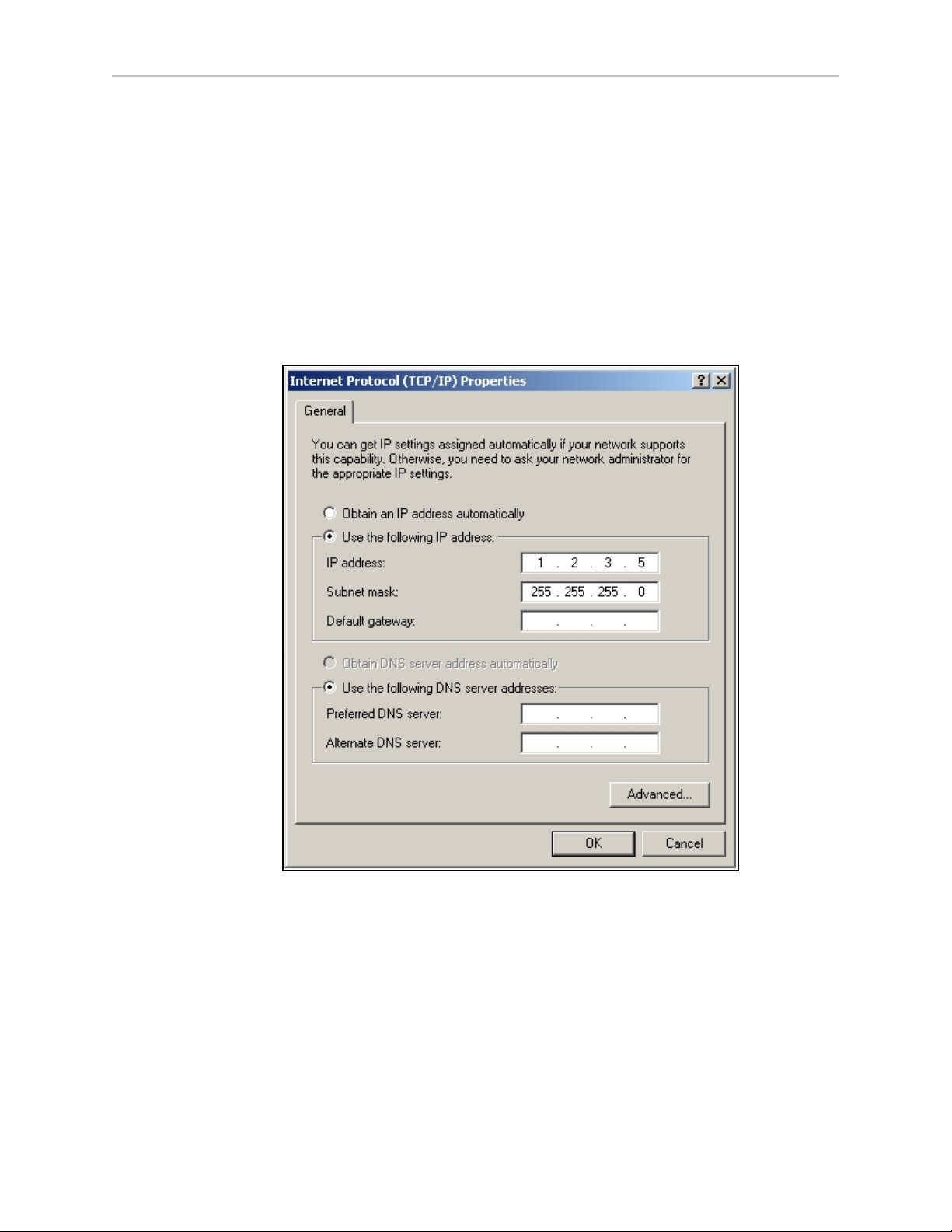
If the robot has not been set up on a wireless network, a local area network will have to be set
up on a separate PC, and configured to talk to the robot over a TCP/IP port. The IP address
should be set to: 1.2.3.5. The Subnet Mask should be 255.255.255.0.
(Windows 7)Start >Control Panel >(Network and Internet >)Network and Sharing Center
>Change adapter settings
Right-click on the LAN Connection, and click on Properties.
From the Properties dialog, scroll to and double-click the Internet Protocol (TCP/IP or
TCP/IPv4) option. In Internet Protocol Properties, click both “Use the following…” radio buttons to enable them, and then type in the IP and netmask values.
Connect the network port of your computer to the platform's Maintenance port. See the figure
Location of Parts in the Payload Bay on page 144.
SetNetGo Access
If the MobilePlanner software is available, use the SetNetGo interface within that software to
access SetNetGo. Otherwise, open a web browser and enter the URL: https://1.2.3.4:
You will be requested to confirm security certificates.
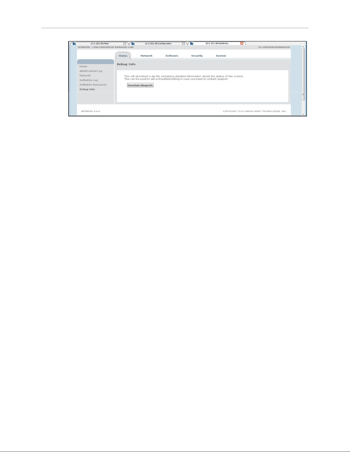
Regardless of how you accessed SetNetGo, you should now have a window similar to the following:
LD Cart Transporter User's Guide, 14766-000 Rev B
Page 18 of 190
Page 19
Chapter 1: Introduction
1.
From the SetNetGo screen, select:
Status >Debug Info
This will display the “Download debug info” button.
2.
Click Download debug info.
3.
Save the downloaded file, and attach it to your support request.
LD Cart Transporter User's Guide, 14766-000 Rev B
Page 19 of 190
Page 20

Page 21

Chapter 2: Safety
2.1 Dangers, Warnings, Cautions, and Precautions
There are six levels of special alert notation used in this manual. In descending order of
importance, they are:
DANGER: This indicates an imminently hazardous electrical situation which,
if not avoided, will result in death or serious injury.
DANGER: This indicates an imminently hazardous situation which, if not
avoided, will result in death or serious injury.
WARNING: This indicates a potentially hazardous electrical situation which,
if not avoided, could result in serious injury or major damage to the
equipment.
WARNING: This indicates a potentially hazardous situation which, if not
avoided, could result in serious injury or major damage to the equipment.
CAUTION: This indicates a situation which, if not avoided, could result in
minor injury or damage to the equipment.
Precautions for Safe Use: This indicates precautions on what to do and what
not to do to ensure safe use of the product.
2.2 What to Do in an Emergency /Abnormal Situation
Press the E-Stop button (a red push-button on a yellow background) and then follow the
internal procedures of your company or organization for an emergency /abnormal situation. If
a fire occurs, use a type D extinguisher: foam, dry chemical, or CO2.
Releasing the Brakes
In case of an emergency or abnormal situation, the transporter can be manually moved.
However, only qualified personnel who have read and understood this manual and the Mobile
Robot LDSafety Guide should manually move the platform. The brakes on the drive wheels can
be released with the brake release button. This requires battery power, and an E-Stop must be
pressed on the robot.
LD Cart Transporter User's Guide, 14766-000 Rev B
Page 21 of 190
Page 22

Releasing an E-Stop
WARNING: If the robot’s E-Stop is triggered, ensure that the cause of the EStop is resolved, and all surrounding areas are clear and safe before releasing
the E-Stop.
2.3 User's Responsibilities
It is the end-user’s responsibility to ensure that the mobile robots are used safely. This
includes:
l
Reading the installation and operation instructions, as well as the Mobile Robot
LDSafety Guide, before using the equipment.
l
Ensuring that the environment is suitable for safe operation of the robot.
If a fleet of mobile robots (two or more) is installed, the Enterprise Manager 1100 must
be used, unless no two robots will ever operate in the same area.
l
Ensuring that anyone working with or near a mobile robot has been adequately trained,
and is following this user’s guide and the Mobile Robot LDSafety Guide, for safe robot
operation.
Chapter 2: Safety
l
Ensuring that the robots are maintained, so that their control and safety functions are
working properly.
General Hazards
CAUTION: The following situations could result in minor injury or damage to
the equipment.
l
Do not ride on the transporter or cart.
l
Do not exceed the maximum weight limit.
l
Do not exceed the maximum recommended speed, acceleration, deceleration, or rotation
limits. See Center of Gravity on page 76 and Acceleration, Deceleration, and Rotation
Limits on page 72.
Rotational speed becomes more significant when the payload’s center of gravity is
farther away (vertically and/or horizontally) from the platform’s center of gravity.
l
Do not drop the robot, run it off a ledge, or otherwise operate it in an irresponsible manner.
l
Do not allow the robot to drive through an opening that has an automatic gate/door
unless the door and robot are configured correctly with the Door Box option.
Refer to the LDPlatform Peripherals Guide for details on the Door Box.
l
Do not get the robot wet. Do not expose the robot to rain or moisture.
l
Do not continue to run the robot after hair, yarn, string, or any other items have become
LD Cart Transporter User's Guide, 14766-000 Rev B
Page 22 of 190
Page 23
Chapter 2: Safety
wound around the platform’s axles, casters, or wheels.
l
Do not use parts not authorized by Omron Adept Technologies, Inc.
l
Do not turn on the robot without the antennas in place.
l
Although the lasers are Class 1 (eye-safe), we recommend you not look directly into
them.
Falling Hazards
WARNING: A mobile robot can cause serious injury to personnel or damage
to itself or other equipment if it drives off of a ledge, such as a loading dock, or
down stairs.
Physical Barriers
The edge of a loading dock, the entrance to downward stairs, or any other substantial drop
that is within the robot’s expected operating area should be physically marked so that the
robot’s navigation laser will see the barrier, and stop before reaching it. The robot’s navigation
laser scans at 203 mm (8 in.) from the floor, so the barrier must cover at least that height.
This needs to be continuous at the site, so that the robot can’t drive around or through it to the
dropoff.
Logical Barriers
You should also use forbidden areas, sectors, or lines with several feet of safety zone (padding)
before the actual dropoff, to ensure that the robot will not try to drive there.
These need to be continuous at the site, so that the robot can’t plan a path to drive around or
between them to the dropoff.
Electrical Hazards
WARNING: The docking station has AC power inside. Its covers are not interlocked.
l
Do not use power extension cords with the docking station unless properly rated.
l
Never access the interior of the platform with the docking station attached.
l
Immediately disconnect the battery after opening the battery compartment door.
Avoid shorting the battery terminals.
l
Do not use any charger not supplied by Omron Adept Technologies, Inc.
l
If any liquid is spilled on the robot, power off the robot, clean up all possible liquid, and
allow the robot to air dry thoroughly before restoring power.
LD Cart Transporter User's Guide, 14766-000 Rev B
Page 23 of 190
Page 24
Pinch Hazards
Latching System Latch
CAUTION: Pinch hazard. The latch of the LD Cart Transporter can pinch you
if you are not careful. Keep your hands clear of the transporter when it is in
action.
Latching System Belt/Pulley
CAUTION: Pinch hazard. During maintenance on the latch mechanism, the
belt and pulley can pinch you if you are not careful. Keep your hands clear of
the belt and pulley when they are in action.
HMIPost-Cart Gap
CAUTION: Pinch hazard. The coupling action of the LD Cart Transporter and
cart can pinch you if the cart payload is incorrectly designed, and you are not
careful. Keep your hands clear of the space between the HMI post and cart
when the transporter and cart are coupling.
Chapter 2: Safety
Robot Covers
CAUTION: Pinch hazard. The covers are held in place with strong magnets,
which can pinch you if you are not careful. Follow the instructions in the Maintenance chapter for handling covers.
NOTE:The hazard presented by the platform cover magnets is slight enough that
the covers and their magnets do not have warning labels.
Magnetic Field Hazards
Robot Covers
WARNING: Magnetic fields can be hazardous to pacemaker wearers. Pacemaker wearers stay back 30 cm (12 in.) from the covers, which are held in
place with strong magnets.
LD Cart Transporter User's Guide, 14766-000 Rev B
Page 24 of 190
Page 25
Chapter 2: Safety
Docking Funnel
WARNING: Magnetic fields can be hazardous to pacemaker wearers. Pacemaker wearers stay back 30 cm (12 in.) from the underside of the cart transporter, which is exposed during certain maintenance procedures for which the
transporter is tipped on its side.
Cart Magnet
The underside of the cart has a strong magnet, used to signal the transporter that it is in place.
This can be a hazard to pacemaker wearers, if they get too close to it.
WARNING: Magnetic fields can be hazardous to pacemaker wearers. Pacemaker wearers stay back 30 cm (12 in.) from the bottom of the cart.
Qualification of Personnel
It is the end-user’s responsibility to ensure that all personnel who will work with or around
mobile robots have attended an appropriate Omron training course and have a working knowledge of the system. The user must provide any necessary additional training for all personnel
who will be working with the system.
As noted in this and the Mobile Robot LDSafety Guide, certain procedures should be performed
only by skilled or instructed persons. For a description of the level of qualification, we use the
standard terms:
l
Skilled persons have technical knowledge or sufficient experience to enable them to
avoid the dangers, electrical and/or mechanical
l
Instructed persons are adequately advised or supervised by skilled persons to enable
them to avoid the dangers, electrical and/or mechanical
All personnel must observe industry-prescribed safety practices during the installation, operation, and testing of all electrically-powered equipment.
WARNING: Before working with the robot, every entrusted person must confirm that they:
l
Have the necessary qualifications
l
Have received the guides (both this guide, and the Mobile Robot LDSafety Guide)
l
Have read the guides
l
Understand the guides
l
Will work in the manner specified by the guides
LD Cart Transporter User's Guide, 14766-000 Rev B
Page 25 of 190
Page 26

Chapter 2: Safety
Payload Movement and Transfer
Monitoring and confirmation of the status of robot payload movement and transfer to or from
facility equipment is the end-user’s responsibility.
Payload transfer problems must trigger a robot E-Stop, preventing the robot from moving until
an Operator has resolved the problem and confirmed that the system is safe to use. This handling of payload transfer problems is the end-user’s responsibility.
Providing an interlock between the robot and facility equipment is the user’s responsibility.
Configurable Warning Buzzer
The LD Cart Transporters have a configurable warning buzzer. It is the user’s responsibility to
configure this buzzer as appropriate for the facility in which the robot will be operating.The
buzzer will sound whenever the robot is moving backwards or is turning. Other situations are
configurable.
The buzzer is configured with MobilePlanner, using the following parameters:
NOTE:These parameters are only available with the Mobile Robot Software Suite
5.0 and later.
l
DriveWarningEnable
NOTE:If this parameter is set to False, the remaining parameters will not be
displayed.
WARNING: Disabling the DriveWarningEnable parameter violates the
JIS D6802 standard. It is strongly recommended that you leave this set
to True.
l
DoNoWarnDrivingForwards
Default:False
l
DoNotWarnTurningInPlace
Default:False
l
DriveWarningLoudMilliseconds
Default:500. If DriveWarningQuietMilliseconds is 0, this parameter is irrelevant.
l
DriveWarningQuietMilliseconds
Default:500. This is the length of time between warnings that the buzzer is silent. Setting this to 0 will cause a continuous warning.
Multi-Vehicle Avoidance
When multiple vehicles are operating in the same operating space, they must be connected to
an Enterprise Manager 1100 (EM) via WiFi. The EM helps prevent collisions by sharing
vehicles’ dynamic X, Y, Theta, size, and path-planning information with each other. Vehicles
then factor this data into their obstacle avoidance. This is not an interlocked method of
LD Cart Transporter User's Guide, 14766-000 Rev B
Page 26 of 190
Page 27

preventing collisions. Ultimately, it is the end-user/integrator's responsibility to provide an
interlocked method of preventing collisions.
NOTE:If two robots are approaching each other, neither will not see the other
because the incoming laser beams are detected as reflected beams. Because of this,
any installation with more than one robot working in the same operating space
must be managed by the same Enterprise Manager 1100.
Traffic Control
A "switchable forbidden area" can be programmed on the map to prevent the robot from entering an area based on the state of a discrete input. If this input is set from another vehicle, such
as a forklift, while it is in that area, then the robot shall not be allowed to enter that area.
Passing Lanes
Since the LD Cart Transporter technology does not use fixed tracks to guide the robots, the concepts of passing lanes and human safety areas are not relevant.
2.4 Environment
Chapter 2: Safety
General Environmental Conditions
It is the end-user’s responsibility to ensure that the operating environment of the platform
remains safe for the platform. If there are areas that are not safe for the platform to travel in,
those areas should be physically blocked off so that the platform’s scanning laser will detect
the barriers, and the platform will not attempt to drive there. These areas can also be blocked
off with forbidden zones in the MobilePlanner software, but that should be in addition to physical barriers.
Public Access
The LD Cart Transporter is designed for operating in indoor industrial or professional environments. It must be deployed in a manner that takes into account potential risks to personnel
and equipment. The product is not intended for use in uncontrolled areas without risk analysis, for example, areas open to general public access. Use in such areas may require deployment of additional safety measures.
Clearance
The LD Cart Transporter is designed to operate in an environment that is generally level and
has no doors or other restricted areas too narrow for the robot. It is the user’s responsibility to
ensure that adequate clearance is maintained on each side of the robot, so that a person cannot
get trapped between the robot and a wall or other fixed object. You should consult the applicable standards for your area. An exception to side clearance can exist at pickup and dropoff
locations where the robot must get close to conveyors or other fixed objects.
The primary direction of travel of the LD Cart Transporter is forward. When the transporter is
turning in place, with no forward movement, the detection of an obstacle in its path of rotation
will not trigger an E-Stop.
LD Cart Transporter User's Guide, 14766-000 Rev B
Page 27 of 190
Page 28

Obstacles
If the LD Cart Transporter will be entering high-traffic areas, the user must take appropriate
precautions to alert people in those areas that a robot might enter. If the traffic consists of other
machines, the user must adjust the robot‘s and/or the other machine’s parameters to reduce
the risk of a collision.
2.5 Intended Use
The LD Cart Transporter is not intended for use in any of the following situations:
l
In hazardous (explosive) atmospheres
l
Uncontrolled areas, for example, areas open to general public access.
Application in such areas may require deployment of additional safety measures, and
risk analysis.
Chapter 2: Safety
WARNING: Personnel who work with or around the robot should not stand
close to the robot when it is turning in place (with no forward motion).
LD Cart Transporters are designed for operating in industrial or professional environments. They must be deployed in a manner that takes into account potential risks to
personnel and equipment.
l
In the presence of ionizing or non-ionizing radiation
l
In life-support systems
l
In residential installations
l
Where the equipment will be subject to extremes of heat or humidity.
l
In mobile, portable, marine, or aircraft systems
NOTE:The gyroscope used to assist in navigation in LD Cart Transporters
requires a stationary environment for optimum accuracy. Therefore, we do
not recommend them for use on a ship, train, aircraft, or other moving environment.
Non-Intended Use
WARNING: The instructions for operation, installation, and maintenance given in this guide and the robot user’s guide must be strictly
observed.
Non-intended use of LD robots can:
l
Cause injury to personnel
l
Damage the robot or other equipment
LD Cart Transporter User's Guide, 14766-000 Rev B
Page 28 of 190
Page 29

l
Reduce system reliability and performance
The body of the robot must not come into contact with liquids. The drive wheels can tolerate
damp floors, but the body of the robot must remain dry.
If there is any doubt concerning the application, ask Omron Adept Technologies, Inc. to determine if it is an intended use or not.
Robot Modifications
If the user or integrator makes any changes to the LD platform or cart, it is their responsibility
to ensure that there are no sharp edges, corners, or protrusions.
Note that any change to the platform or cart can lead to loss in safety or functionality. It is the
responsibility of the user or integrator to ensure that all safety features are operational after
modifications.
2.6 Battery Safety
l
Batteries must be stored upright at 5° to 60° C (41° to 140° F).
l
Do not expose batteries to water.
Chapter 2: Safety
l
If a battery is found to be leaking, do not expose it to water. If possible, submerge it in
mineral oil and contact Omron Adept Technologies, Inc.
l
In case of a fire, use a type D extinguisher: foam, dry chemical, or CO2.
2.7 Additional Safety Information
Accidental Cart Separation
In the unlikely event that the cart becomes unlatched from the LDplatform while in motion,
the brakes are designed to stop the cart within six feet.
Mobile Robot LDSafety Guide
Omron Adept Technologies, Inc. provide other sources for more safety information:
The Mobile Robot LDSafety Guide provides detailed information on safety for LDPlatforms. It
also gives resources for information on relevant standards. It ships with each mobile robot.
LD Cart Transporter User's Guide, 14766-000 Rev B
Page 29 of 190
Page 30

Page 31

Chapter 3: Setup
CAUTION: Possible battery damage. Immediately charge the battery to a full
charge upon receipt to avoid the risk of discharging the battery below a usable
state, which would require battery replacement.
NOTE:Effective April 1, 2016, IATAregulations require that air-shipped lithium
ion batteries (UN3480, PI 965) must be transported at a state of charge not exceeding 30%. You should charge the battery completely as soon as you receive it.
Overview
In general, setup is the physical preparation of the platform and cart and physically marking
parking goal locations on your facility floor. Marking the parking goals on the floor is for
human use. An LD Cart Transporter doesn’t use those markings, although we recommend you
mark them in any case, to prevent someone from placing something there that would prevent
a cart from being parked.
The physical preparation of the platform includes attaching the horizontal tubes that support
the side lasers to the HMI post.
Setup also includes generating a map of the workspace and configuring the robot with the
MobilePlanner software to perform useful tasks.
Tasks
This overview covers the LD Cart Transporter starter kit, which includes the transporter with
all components needed for use with a cart, a docking station, and software needed for navigation.
l
Install the battery in the platform. See Installing the Battery on page 45.
l
Fully charge the battery, either outside of or inside the platform.
l
Set up the wireless Ethernet for the platform. See Configuration on page 61.
l
Install the HMI post‘s side laser support tubes.
l
Install the docking station. See Installing the Docking Station on page 50.
l
Install the cart’s manual brake-release cable and lever.
l
Configure the robot for your environment, so it can perform useful tasks.
This includes generating the map that the LD Cart Transporter will use for its navigation. This procedure and parameter configuration is covered in the Mobile Robot Soft-
ware Suite User's Guide.
l
Mark the location and orientation of the goals where the cart can be parked. This allows
a person to place a cart where the transporter can find it.
LD Cart Transporter User's Guide, 14766-000 Rev B
Page 31 of 190
Page 32

It will also help keep someone from putting something other than a cart in that area,
which could prevent a cart from being parked there.
l
Configure the MobilePlanner software, so an transporter can pick up and drop off carts.
This includes modifying the map that the transporter uses for its navigation. The configuration is covered in the Mobile Robot Software Suite User's Guide.
3.1 Transport and Storage
Use a forklift, pallet jack, or similar device to move the shipping containers.
The containers must always be shipped and stored in an upright position in a clean, dry area
that is free from condensation. Do not lay the containers on their sides or any other nonupright position.
LD Cart Transporter
The LD Cart Transporter system, which includes a cart, is shipped in one crate, along with the
docking station, joystick, and all components except for the battery.
The system must be shipped and stored in a temperature-controlled environment, from 5° to
60° C (41° to 140° F). The recommended humidity range is 5 to 95%, non-condensing. It should
be shipped and stored in the supplied shipping crate, which is designed to prevent damage
from normal shock and vibration. You should protect the crate from excessive shock and vibration.
Chapter 3: Setup
The transporter alone weighs 79 kg (175 lb).
The crate for the transporter measures 1156 x 794 x 1765 mm (45.5 x 31.25 x 69.5 in.), and
weighs 98 kg (216 lb). The weight, as shipped, is 199 kg (439 lb).
Battery
NOTE:If you purchased spare batteries, this section applies to them, also.
The battery is shipped in a separate carton, not inside the platform or platform crate.
If the battery needs to be stored, the manufacturer recommends 5° to 60° C (41° to 140° F).
The battery should start storage fully-charged. If the battery will be stored for an extended
period, it should be recharged periodically to avoid total discharge, which will damage the battery. Fully recharging a battery every six months is sufficient to keep it charged enough to
avoid damage.
The battery must be stored upright, in a dry location.
Standalone Cart
Carts can be purchased as an option, if you need more carts than transporters.
The box measures 1092 x 635 x 711 mm (43 x 25 x 28 in.). The cart in the box weighs 28 kg (62
lb) alone. If the cart and box are on a pallet the weight is 44.5 kg (98 lb).
The standalone cart weighs 22.7 kg (50 lb).
Each cart comes with caster brakes, which require the installation of a brake-release lever. See
Installing the Cart Brake Release on page 55.
LD Cart Transporter User's Guide, 14766-000 Rev B
Page 32 of 190
Page 33

3.2 Before Unpacking
Carefully inspect all shipping containers for evidence of damage during transit. If any damage
is indicated, request that the carrier’s agent be present at the time the containers are unpacked.
3.3 Unpacking
Before signing the carrier’s delivery sheet, compare the actual items received (not just the packing slip) with your equipment purchase order. Verify that all items are present and that the
shipment is correct and free of visible damage.
l
If the items received do not match the packing slip, or are damaged, do not sign the
receipt.
l
If the items received do not match your order, please contact Omron Adept Technologies, Inc. immediately.
Retain the containers and packing materials. These items may be necessary to settle claims or,
at a later date, to relocate the equipment.
A complete LD Cart Transporter will come in two packages:
l
The battery is shipped in a cardboard carton.
l
The transporter and cart are shipped in a wooden crate.
Chapter 3: Setup
This includes the HMI post, with the detached side laser support tubes.
This also includes the joystick, docking station, and any accessories ordered, all in cardboard cartons inside the transporter crate.
Battery
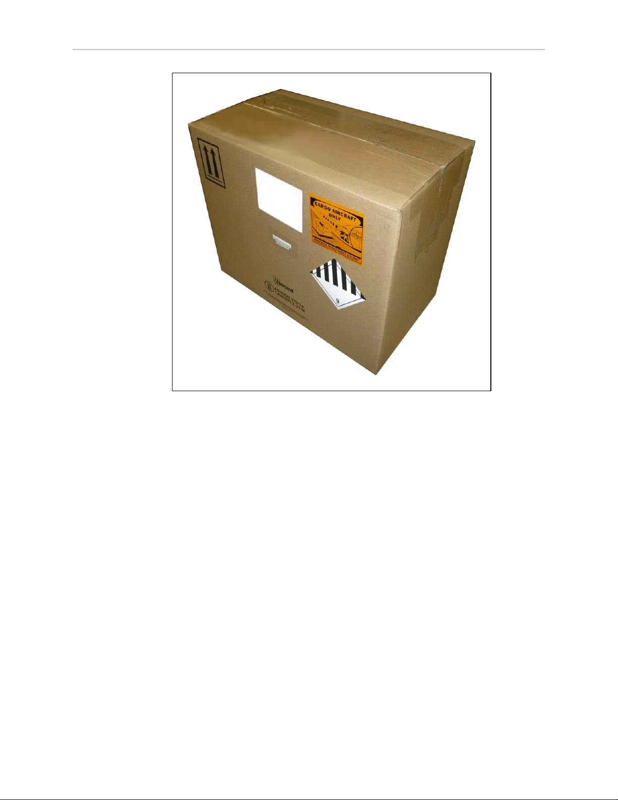
The battery is shipped separately from the transporter. Locate the box that contains the battery
before continuing. Refer to the following figure.
LD Cart Transporter User's Guide, 14766-000 Rev B
Page 33 of 190
Page 34
Chapter 3: Setup
Figure 3-1. Battery Shipping Container
The battery box measures 311 x 540 x 457 mm (12.25 x 21.25 x 18 in.).
NOTE:The battery weighs 19 kg (42 lbs). There are recesses at the front and
the back of the battery, to aid in lifting it.
LD Cart Transporter User's Guide, 14766-000 Rev B
Page 34 of 190
Page 35
LD Cart Transporter
Chapter 3: Setup
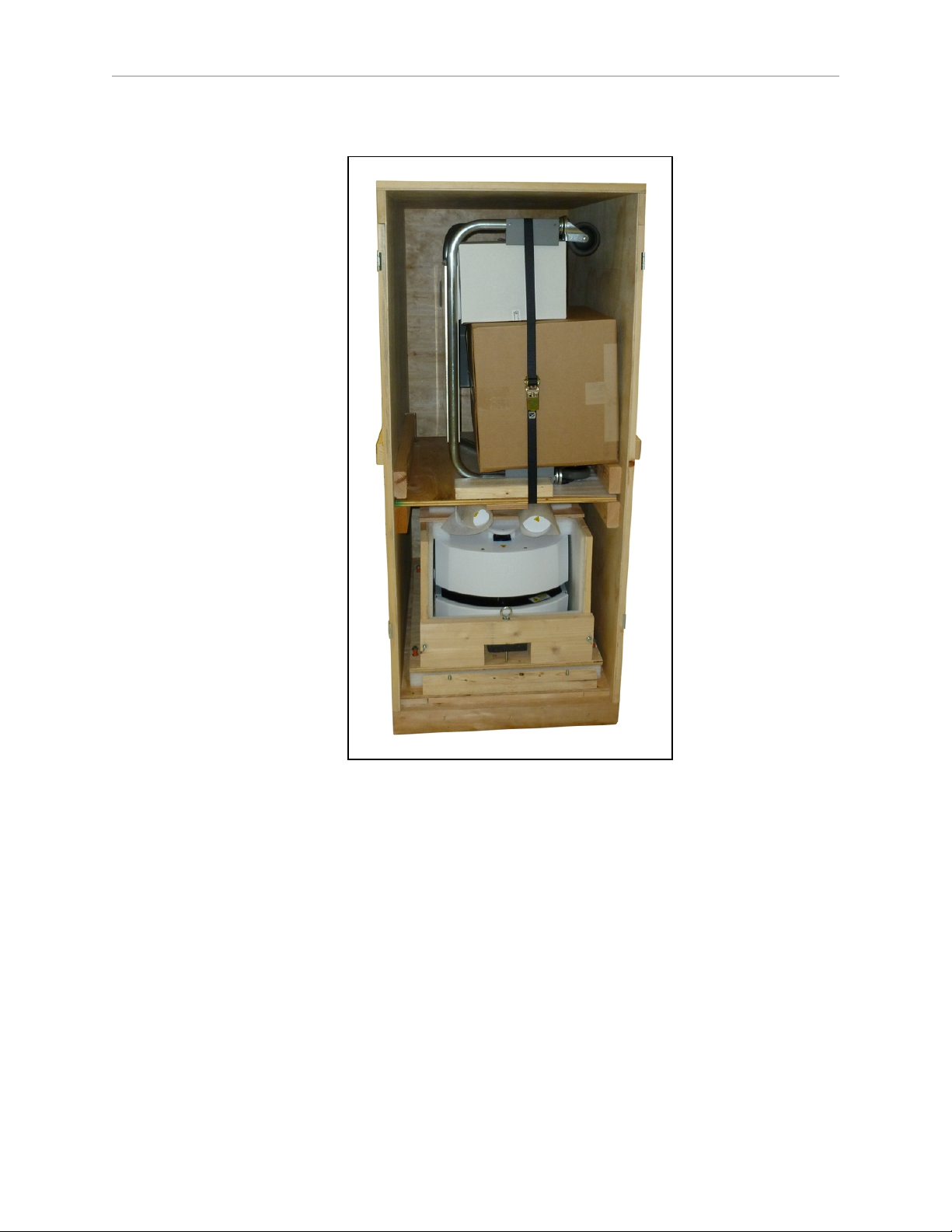
Figure 3-2. Cart and LD Cart Transporter in Crate
The cart crate measures 1156 x 794 x 1759 mm (45.5 x 31.25 x 69.25 in.).
NOTE:The preceding figure includes accessory boxes for Call/Door Boxes.
Removing the Front Panel
The front panel of the transporter crate doubles as a ramp, for rolling the transporter off of the
crate base.
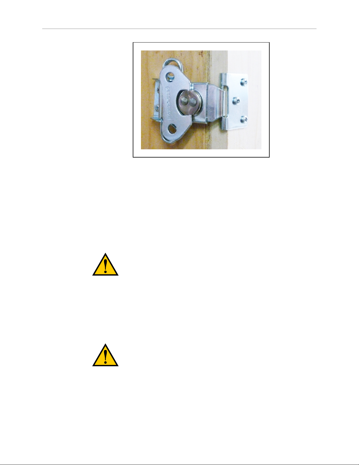
1.
Release the latches that hold the front panel to the crate.
There are four spring-loaded latches.
LD Cart Transporter User's Guide, 14766-000 Rev B
Page 35 of 190
Page 36
Chapter 3: Setup
Figure 3-3. Spring-loaded Latch
2.
Remove the front panel, and set it aside.
This will be used as a ramp, to roll the transporter off of the crate base.
Removing the Cart
The cart is strapped, on its side, to a shelf in the upper part of the transporter crate.
1.
Slide the shelf out of the crate far enough to access the restraining strap.
2.
Remove the cardboard box from the cart shelf.
CAUTION: Due to the weight and height of this cardboard box, two
people should work together to lift it down.
This contains the dock and the joystick, as well as miscellaneous cords.
If accessories, such as call boxes, are ordered, they will be on the shelf, but not in the
large cardboard box.
You may need to loosen the strap to remove the box or boxes.
3.
Remove the straps from the cart, and then the cart itself.
CAUTION: Due to the weight and height of the cart, two people should
work together to lift it down.
4.
Remove the shelf from the crate.
LD Cart Transporter User's Guide, 14766-000 Rev B
Page 36 of 190
Page 37
Chapter 3: Setup
Removing the Upper Body of the Crate
1.
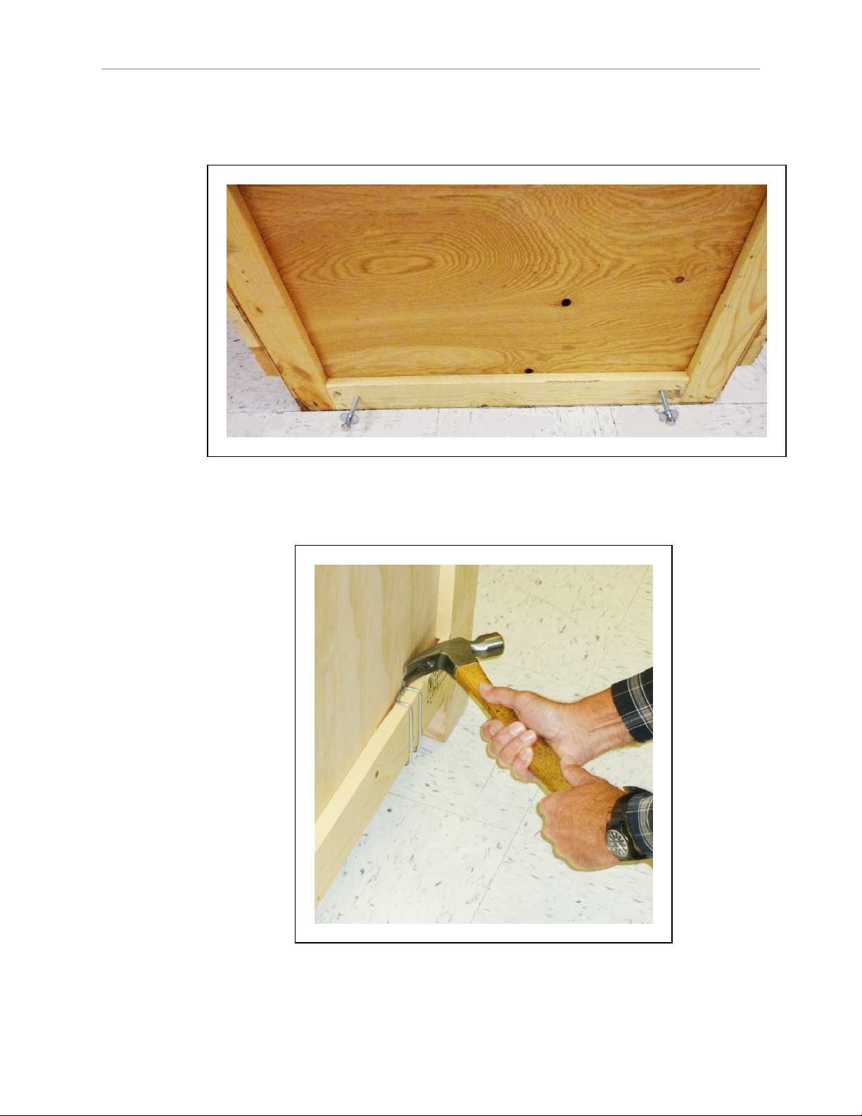
Remove the two lag bolts and washers from the back of the crate, at the bottom.
Figure 3-4. Crate Bottom-rear Lag Bolts
2.
Remove two Klimp fasteners at each side holding the upper body of the crate to the
base.
Figure 3-5. Removing a Klimp Fastener
3.
Slide the upper body of the crate off of the base.
LD Cart Transporter User's Guide, 14766-000 Rev B
Page 37 of 190
Page 38

Chapter 3: Setup
Take care as you slide it over the HMI post, watching the clearance between the crate
and the HMI post components.
The transporter will still be held securely by the base of the crate.
Repacking for Relocation
If the transporter or other equipment needs to be relocated, reverse the steps in the installation
procedures in this chapter. Reuse the original packing crates and materials and follow all
safety notes used for installation. Improper packing for shipment will void your warranty.
The transporter must always be shipped in an upright orientation.
3.4 Setting Up an LD Cart Transporter
The transporter is shipped with the HMI post installed. This includes the Operator panel at
the top of the HMI post. You will have to:
l
Mount the horizontal support tubes, with side lasers, to the post
The side lasers are already mounted on the outer ends of these tubes, and their cables
are already connected through the openings in the HMI post.
l
Roll the transporter off of the crate, down the ramp
l
Remove the pins holding the drive wheels up
l
Install the battery
l
Install the dock, for charging the transporter‘s battery
This should have already been removed from the crate.
l
Set up your wireless system
This is covered in Settings and Configuration on page 61.
Mounting the Side Lasers
The two side lasers are mounted on the ends of horizontal tubes that will be attached to the
HMI post, and braced to the HMI post base.
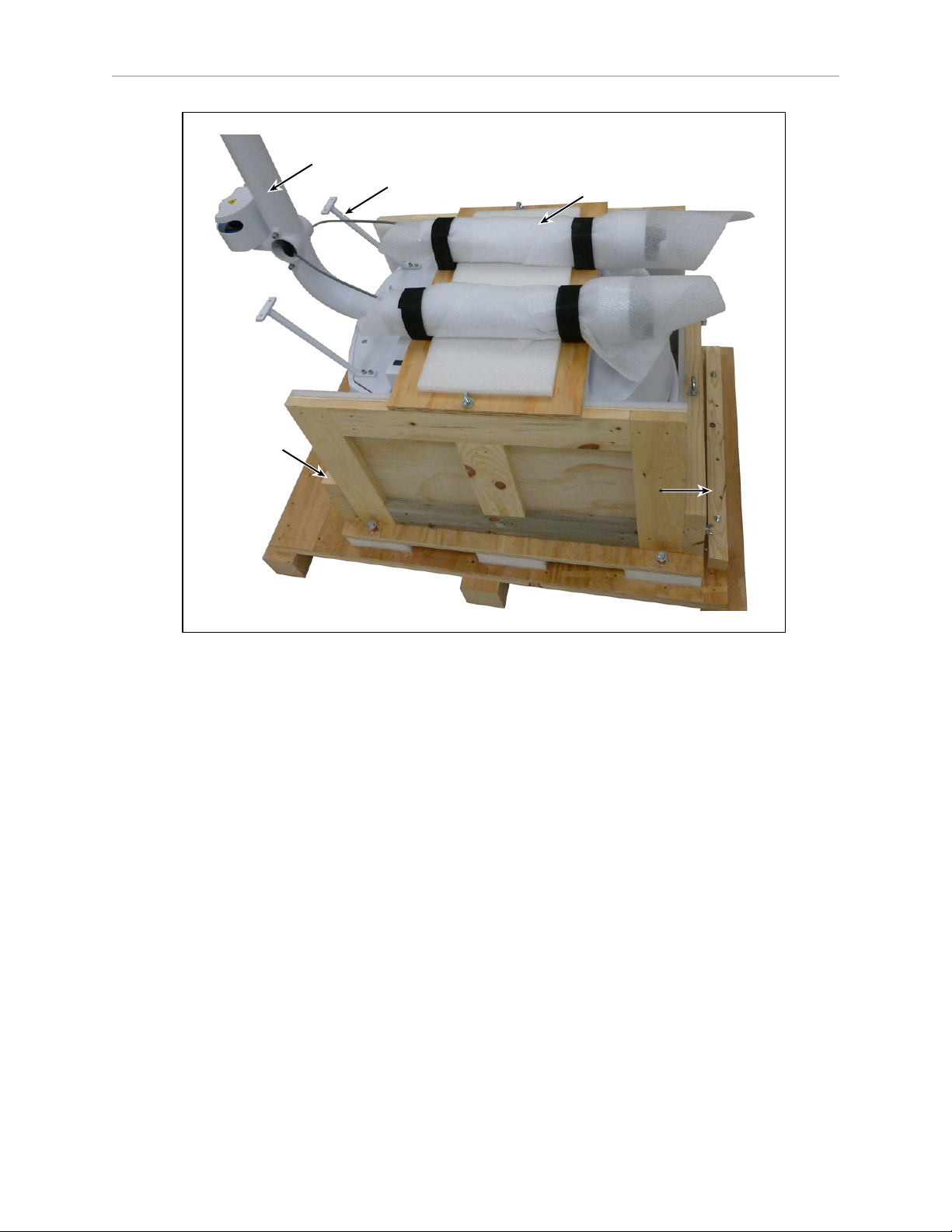
As shipped, the horizontal tubes with side lasers will not be attached to the HMI post. A
wooden board that spans the width of the transporter supports them during shipping. See the
following figure.
LD Cart Transporter User's Guide, 14766-000 Rev B
Page 38 of 190
Page 39
Chapter 3: Setup
HMI Post
Laser Support Arm x 2
Support Arm Brace x 2
Rear
Brace
Front
Brace
Mounting the Side Laser Support Tubes
This procedure involves minor routing of wiring for the rear-facing laser. This wiring must be
in place before the support tubes are fully-installed.
Figure 3-6. LD Cart Transporter on Crate Base
LD Cart Transporter User's Guide, 14766-000 Rev B
Page 39 of 190
Page 40
Chapter 3: Setup
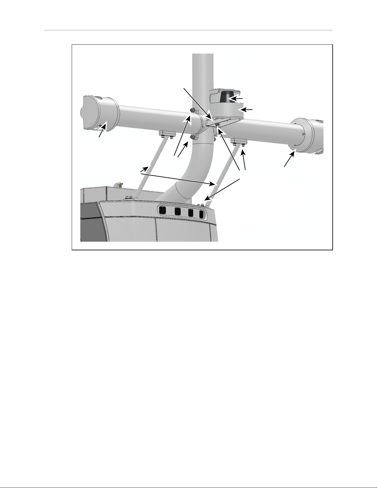
M6
M5
Side Laser
Flange
HMI
Post
Support
Tube Braces
Left Support Tube
Right Support Tube
HMI
Post
Side Laser
Guard
M5: 10x Washer
Lock Washer,
M5 SHCS SS
M6: 4x Washer
Lock Washer,
M6 SHCS SS
Rear-facing Laser
Laser Guard
Rear-facing
Laser Bracket
Figure 3-7. Side Lasers, Support Tubes, Rear-facing Laser
There are two side laser support tubes that attach to support braces that are anchored to the
HMI post base. As shipped, all wiring is already connected, and the support braces are
attached to the HMI post base.
1.
Attach each support tube to a support brace with two M5 screws, lock washers, and
washers.
2.
For the left support tube, ensure that:
l
l
l
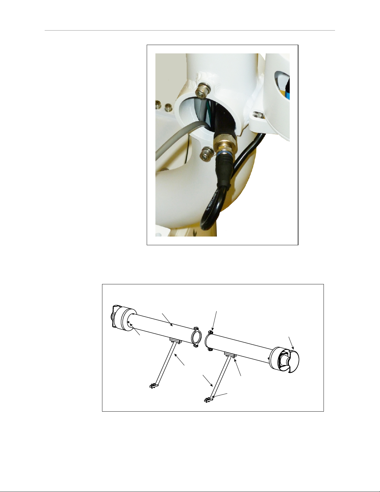
the cable and connector for the rear-facing laser, coming from the HMI post, are
tucked inside the left support tube
the cable is connected to the cable from the rear-facing laser.
See the following figure.
the cable for the rear-facing laser goes through the notch in the HMI post, where
it attaches to the support tube flange
LD Cart Transporter User's Guide, 14766-000 Rev B
Page 40 of 190
Page 41
Chapter 3: Setup
Laser Guard
Support
Tube
Support Braces
Washer, Lock Washer,
M5 SHCS SS Screw (x8)
Screw, BHCS,
M4 SS (x8)
Washer, Lock Washer,
M6 SHCS SS Screw (x4)
Figure 3-8. Connector and Cable for the Rear Laser
3.
Attach the flange of each support tube to the HMI post with two M6 screws, lock washers, and flat washers.
Figure 3-9. Side Laser Support Tubes
LD Cart Transporter User's Guide, 14766-000 Rev B
Page 41 of 190
Page 42
Chapter 3: Setup
Rear
Brace
Front Panel/
Ramp
Battery
Access
Cover
Eye Bolt
Chassis
Support
Board
4.
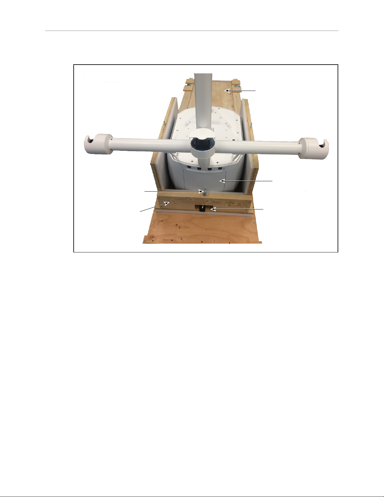
Remove the horizontal board that spans the top of the transporter by removing the two
wing nuts. See Figure 3-6.
Figure 3-10. Side Lasers Installed
Removing the Lower Crate Braces
For the following steps, refer to the preceding figure.
1.
Unscrew the two eye bolts that run vertically down through the front and rear braces, to
lower and ultimately free the chassis support board.
The support board runs between the two transporter drive wheels, and is used to support the transporter during transit.
2.
Remove the front brace (wing nuts).
3.
Remove the rear brace.
This will expose the platform battery cover, which you will need to remove to install the
battery.
Rolling the LD Cart Transporter off of the Crate Base
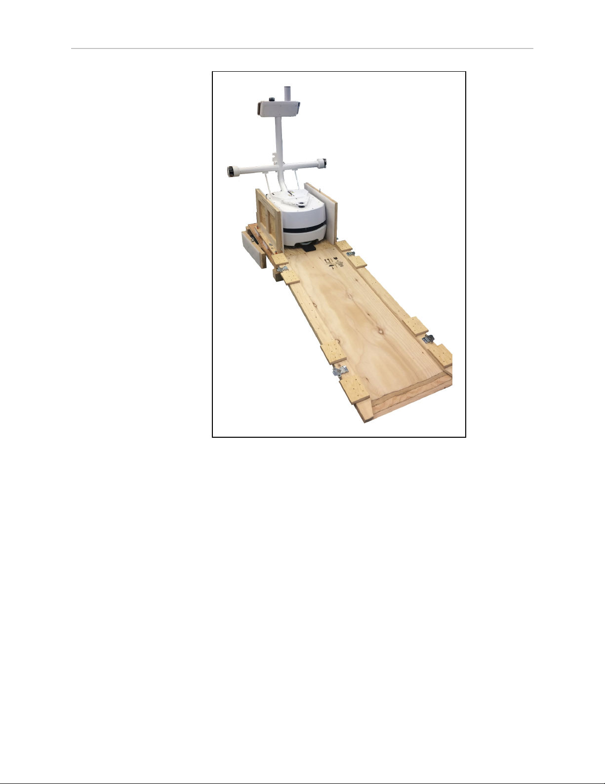
1.
Install the crate front onto the crate base, to serve as a ramp.
There are two hanger bolts that stick up out of the front of the crate base. These fit into
two holes in the end of the ramp.
2.
Roll the transporter off of the crate base and down the ramp.
LD Cart Transporter User's Guide, 14766-000 Rev B
Page 42 of 190
Page 43
Chapter 3: Setup
Figure 3-11. LD Cart Transporter on Crate Base, with Ramp
3.
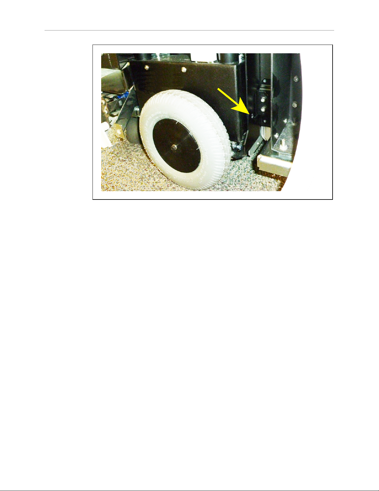
Remove the two wheel pins that held the wheels up during transit.
The wheels are pinned up to protect the motors and drives. When you receive your
transporter, the drive wheels will not touch the ground until you remove the wheel
pins. The wheel pin hole is shown in the following figure.
LD Cart Transporter User's Guide, 14766-000 Rev B
Page 43 of 190
Page 44
Chapter 3: Setup
Figure 3-12. Wheel Pin Hole Location
For each side of the platform:
a.
Remove the side cover a small distance from the platform. Refer to Removing
Covers on page 154.
The light disc PCA cable will still be attached.
b.
Disconnect the cable from the light disc PCA, so the side cover can be moved
completely away from the platform.
This will fully expose the wheel and tire.
c.
Lift the wheel slightly to relieve pressure on the pin.
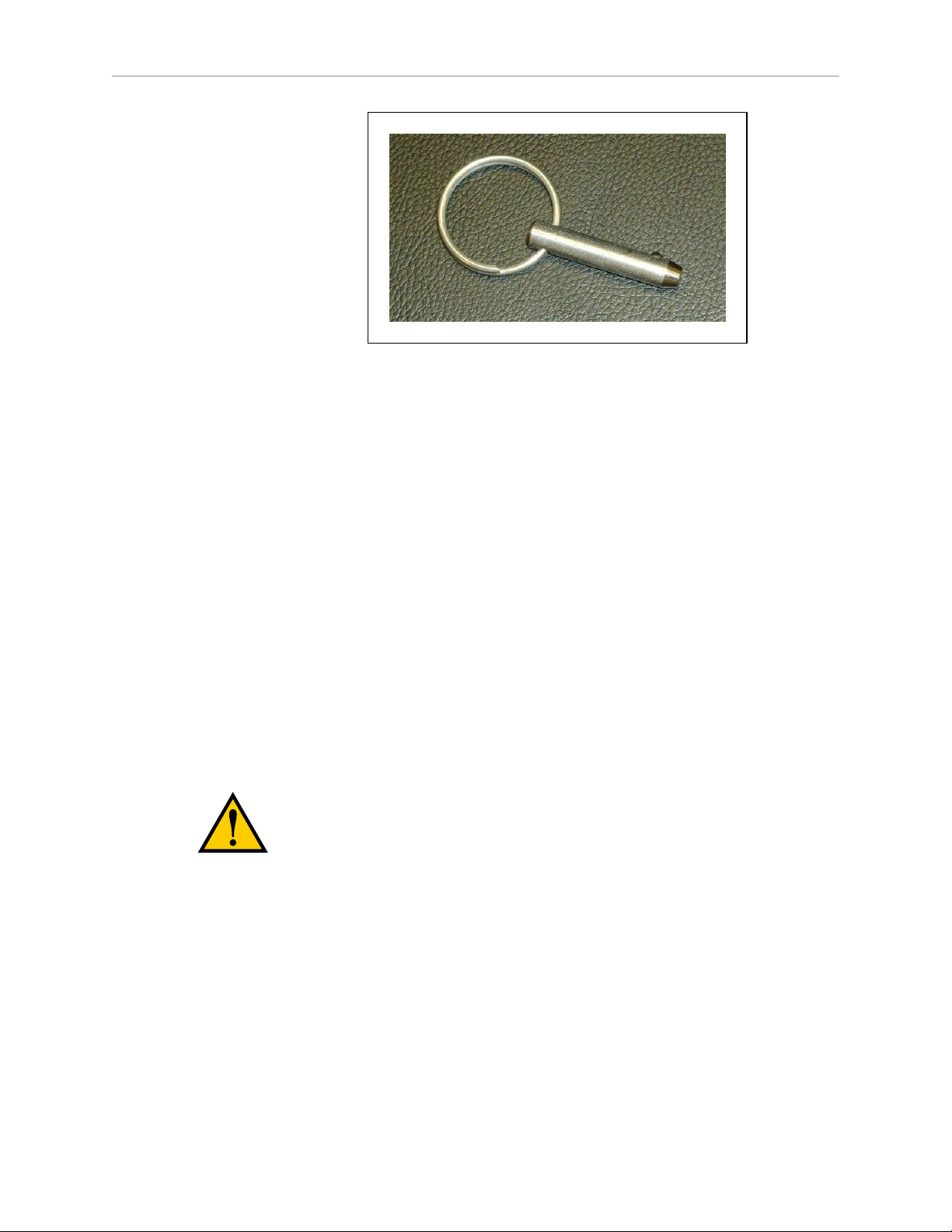
d.
Remove the pin by pulling the ring that is attached.
These pin can be used for later service of either the wheel/tire assemblies or the
entire drive assemblies.
LD Cart Transporter User's Guide, 14766-000 Rev B
Page 44 of 190
Page 45
Chapter 3: Setup
Figure 3-13. Wheel Pin
e.
Lower the wheel to the floor.
The wheels are spring-loaded, and the wheel brakes will be on.
f.
Put the side cover next to the platform, and attach the light disc cable to the light
disc PCA.
g.
Reinstall the side cover.
Installing the Battery
Your platform battery comes with less than 30% charge, to comply with air-shipping regulations. It should be charged as soon as possible, to a full charge.
NOTE:Air shipping regulations require that the LD Cart Transporter be shipped
without the battery installed.
Removing the Battery Cover
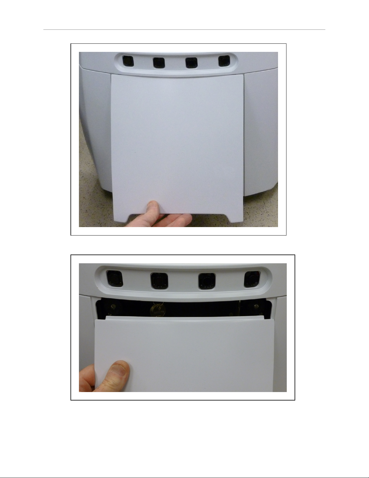
Accessing the battery compartment requires removing the platform's rear cover. This is held in
place with magnets.
CAUTION: Pinch hazard. The magnets holding the cover in place are strong
enough to pinch you if you are not careful.
No tools are needed for either the removal or installation of the battery cover.
NOTE:After removing the cover, place it inner-side down, so the outer surface
doesn't get scratched.
LD Cart Transporter User's Guide, 14766-000 Rev B
Page 45 of 190
Page 46
Chapter 3: Setup
Figure 3-14. Pulling the Bottom of the Rear Cover Out
Figure 3-15. Lowering the Rear Cover
LD Cart Transporter User's Guide, 14766-000 Rev B
Page 46 of 190
Page 47

Chapter 3: Setup
Refer to Removing and Installing LD Cart Transporter Covers in the Maintenance section for
cover removal and installation.
1.
Remove the inner rear platform cover.
a.
Pull the bottom of the cover away from the platform chassis.
This is easiest if you grip it with two hands, toward the center.
b.
Lower the cover down, so its top tab clears the rear outer cover.
2.
Unlatch and open the battery compartment door, at the back of the platform.
The battery compartment door is capable of being locked. You may need to unlock it.
LD Cart Transporter User's Guide, 14766-000 Rev B
Page 47 of 190
Page 48
Chapter 3: Setup
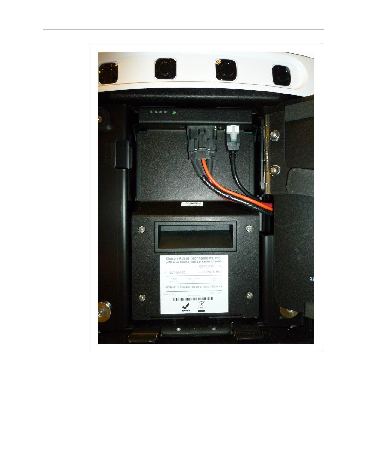
Figure 3-16. Battery Compartment, Connectors
3.
Lift and slide the new battery into the platform body.
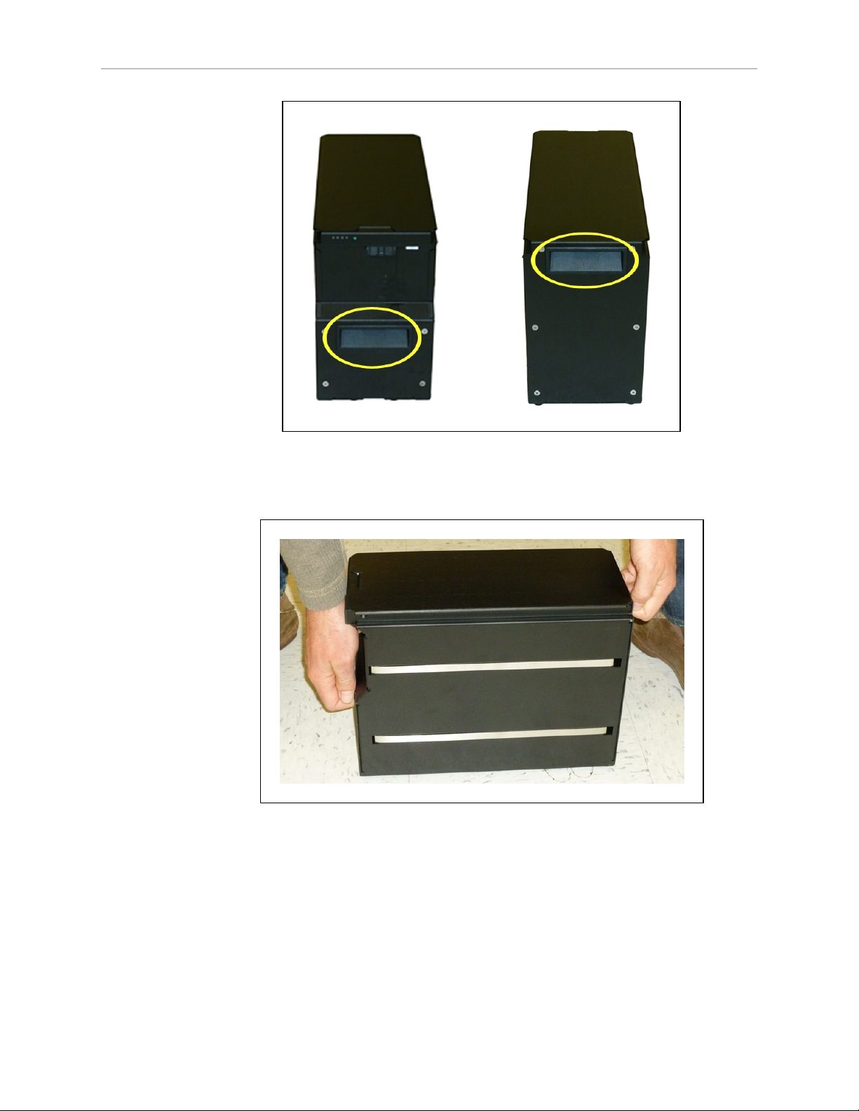
The battery weighs 19 kg (42 lbs).
There are recesses at the front and the back of the battery, to aid in lifting it.
LD Cart Transporter User's Guide, 14766-000 Rev B
Page 48 of 190
Page 49
Chapter 3: Setup
Figure 3-17. Battery Recesses, for Gripping
The battery is designed to be lifted and replaced by one person, using one hand in each
of the grips, as shown in the following figure.
Figure 3-18. Lifting the Battery
The connectors for power and data go toward the rear of the platform.
4.
Attach the battery power and data cables to the connectors at the rear of the battery.
5.
Close the battery compartment door to secure the battery in place.
The battery compartment is designed to hold the battery tightly, so that it will not move
within the compartment, once the door is closed.
6.
Reinstall the inner rear platform cover.
LD Cart Transporter User's Guide, 14766-000 Rev B
Page 49 of 190
Page 50

Chapter 3: Setup
Installing the Docking Station
The automated docking station can be used for either manual or automated charging of your
transporter's battery.
The docking station sits on the floor. It can be attached to a wall with the wall bracket,
attached directly to the floor with screws through its base, or it can sit stand-alone on the floor
with the floor plate, all of which will keep the docking station from moving when the transporter docks. Each docking station comes with a wall bracket and floor plate.
CAUTION: It is very important that the docking station be mounted with one
of these methods, or the transporter will simply move the docking station
when it tries to dock, rather than docking successfully.
Regardless of mounting method:
l
Locate the docking station near an AC outlet with 1 - 2 meters (3.25 - 6.5 ft)of clear
space in front to ease the transporter’s maneuvers onto the docking station.
l
When docked, the rear-facing laser extends almost 5 in. beyond the back of the docking
station. Ensure that you leave enough free space behind the back of the docking station
to allow clearance for this.
The wall-mount bracket provides enough room for this.
l
The top of the docking station foot is spring-loaded, and lifts off of the bottom of the foot
slightly to accommodate variations in the floor surface. The weight of the transporter
will push the top of the foot down.
Requirements
l
100 to 240 VAC, 50 to 60 Hz, 8 A
The station's power converter automatically detects the source voltage.
l
Ambient operating temperature: 5° to 40° C (41° to 104° F)
l
5 to 95% humidity, non-condensing
Wall Bracket Mount
NOTE:This is the recommended method for mounting the docking station.
1.
Attach the docking station mounting bracket to a wall, with the bottom edge of the
bracket 98 ± 20 mm (3.9 ± 0.8 in.) above the floor, using user-supplied anchors and
screws. There is leeway, so you can adjust the height a little bit.
Refer to the following figure:
LD Cart Transporter User's Guide, 14766-000 Rev B
Page 50 of 190
Page 51
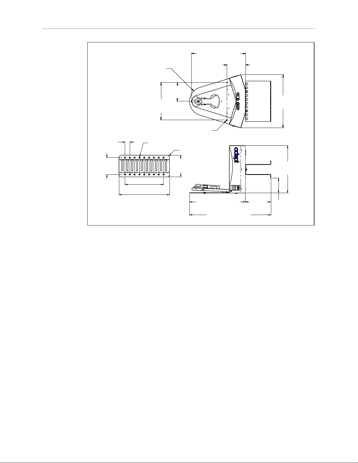
Chapter 3: Setup
369 mm (14.5 in.)
537 mm (21.1 in.)
313 mm
(12.3 in.)
98 ± 20 mm
(3.9 ± 0.8 in.)
168 mm
(6.6 in.)
122 mm
(4.8 in.)
357 mm (14.0 in.)
123 mm
(4.9 in.)
247 mm
(9.7 in.)
3x Ø 6 mm (0.25 in.) Thru
350 mm
(13.8 in.)
R95 mm
(3.8 in.)
267 mm (10.5 in.)
114 mm
(4.5 in.)
203 mm (8.0 in.)
R13 mm (0.5 in.)
Wall Mount Bracket Detail
18x Ø 6 mm (0.25 in.) Thru
8x 25 mm
(1.0 in.)
89 mm
(3.5 in.)
2.
Screw the two shoulder bolts, each with a washer, into the rear of the docking station.
The shoulder bolts are M5 x 4, stainless steel. Their locations are shown in the following figure. Tighten to 9 N-m (80 in-lb).
Figure 3-19. Docking Station, Wall Mount
LD Cart Transporter User's Guide, 14766-000 Rev B
Page 51 of 190
Page 52
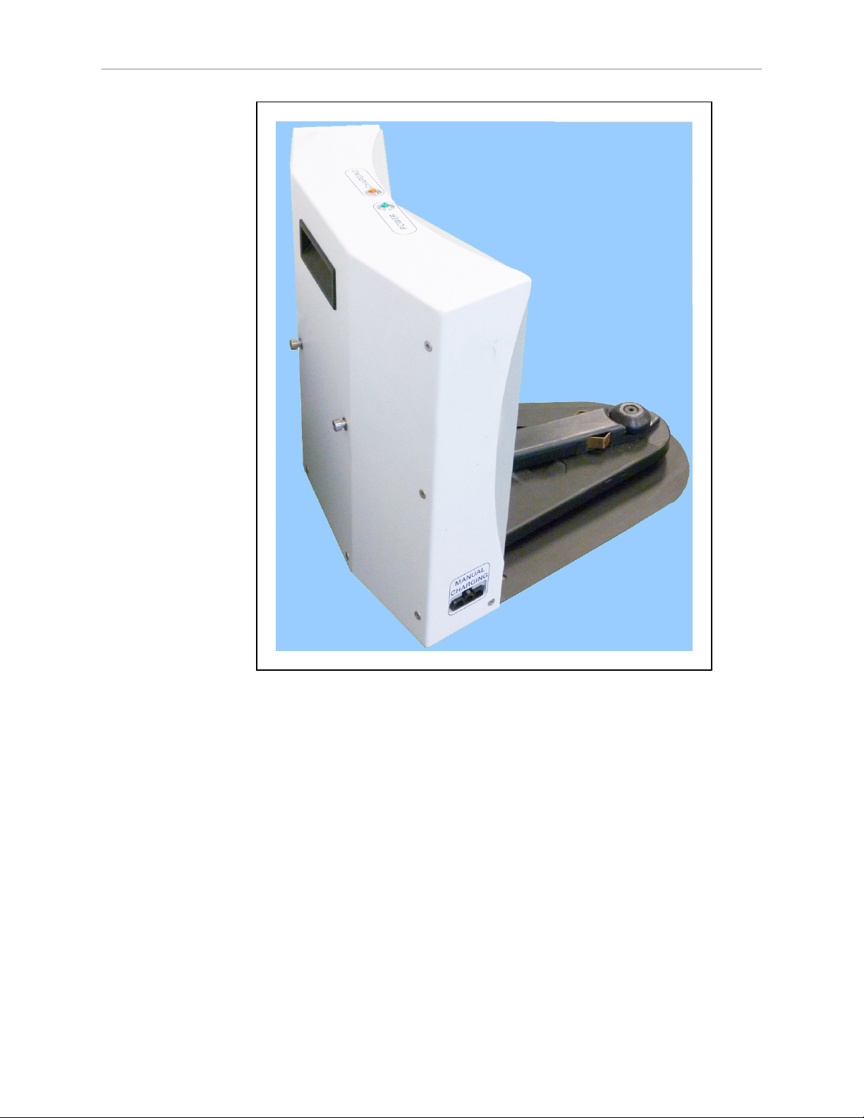
Chapter 3: Setup
Figure 3-20. Rear View of Docking Station with Shoulder Bolts
3.
Lower the docking station down, so the two shoulder bolts on the back of the docking
station slide into the bracket, to secure the docking station to the wall.
Floor-mount, without Floor Plate
NOTE:Because this method permanently attaches the dock to the floor, it may be
subject to building code regulations. It is the user’s responsibility to verify that the
installation is in compliance with local regulations.
Screw the base of the docking station directly to the floor, using three user-supplied screws. For
dimensions of the available holes in the base, refer to Figure 3-19. We recommend M5 self-tapping or M4 drywall screwsfor this.
Floor-mount, with Floor Plate
This mounting method uses the floor plate. The floor plate is not shipped attached to the docking station, so you must attach it for this type of mount. It will be in the crate with the docking
LD Cart Transporter User's Guide, 14766-000 Rev B
Page 52 of 190
Page 53
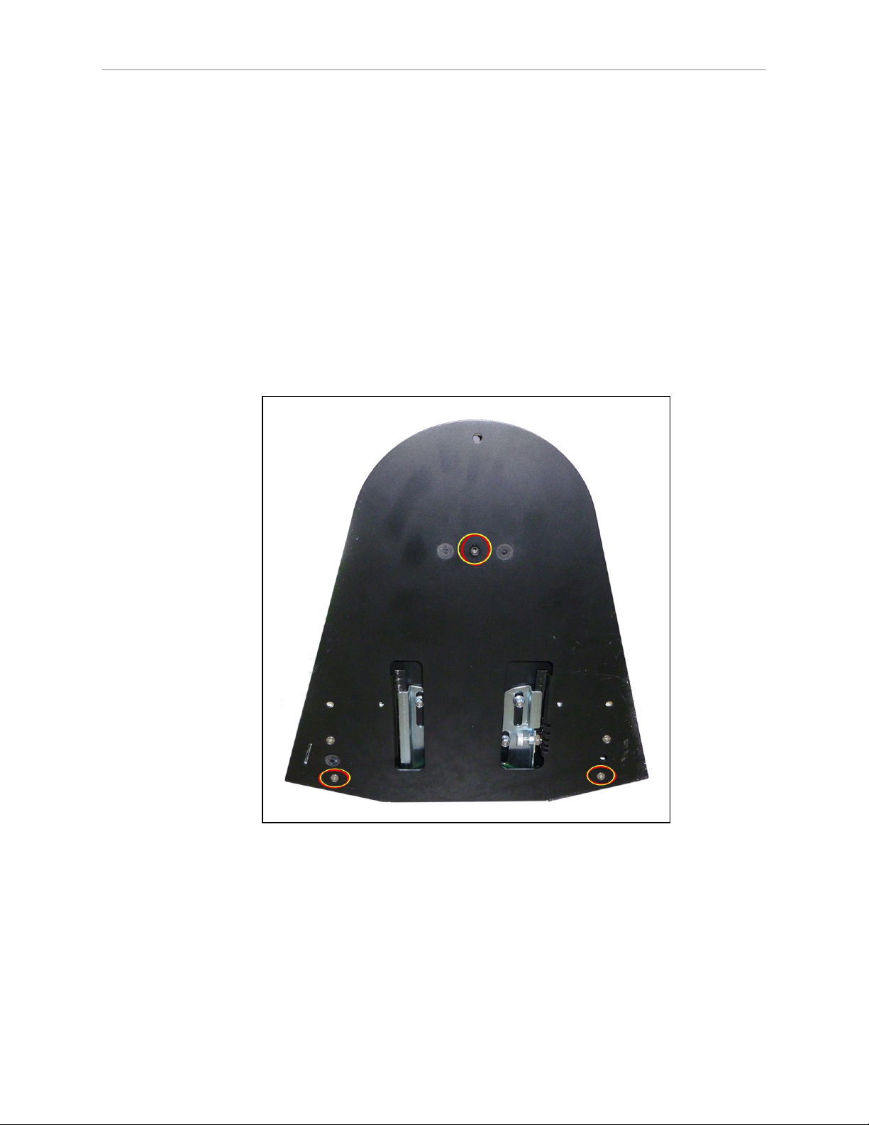
Chapter 3: Setup
station.
Attaching the Floor Plate
Refer to the following figures.
1.
Tip the docking station onto its back, so you can access the underside.
2.
Remove the two lowest screws (M4 x 12 flat-head), if present.
In the following figure, these screws are circled. The location of the third screw hole is
also circled.
3.
Attach the floor plate to the base of the docking station with three M4 x 12 flat-head
stainless steel screws.
The floor plate comes with three screws, so you will have two spares.
The docking station and floor plate do not need to be attached to the floor, as the weight of the
platform on the floor plate will keep the docking station from moving.
Figure 3-21. Underside of Docking Station Foot, Showing Screw Locations
NOTE:These are the three locations for the M4 x 12 flat-head screws. Two are
already in place, and need to be removed before attaching the plate.
LD Cart Transporter User's Guide, 14766-000 Rev B
Page 53 of 190
Page 54
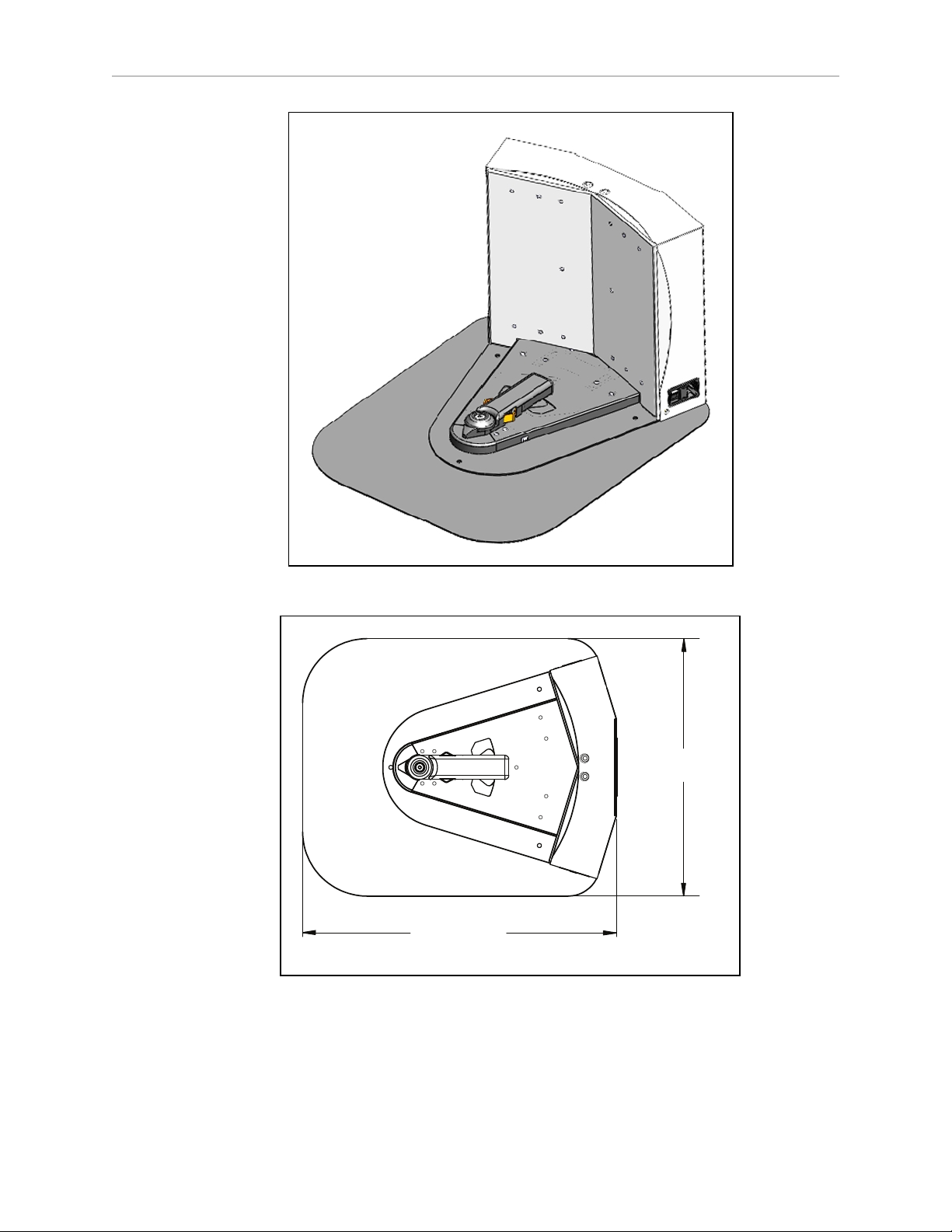
Chapter 3: Setup
406 [16.0]
495 [19.5]
Units are mm [in.]
Figure 3-22. Docking Station, Mounted on Floor Plate
Figure 3-23. Docking Station Floor Plate Dimensions
LD Cart Transporter User's Guide, 14766-000 Rev B
Page 54 of 190
Page 55
Chapter 3: Setup
Power On
Install the power cord and turn the power switch to ON. The power switch is next to the
power plug. The blue power LED indicator should light.
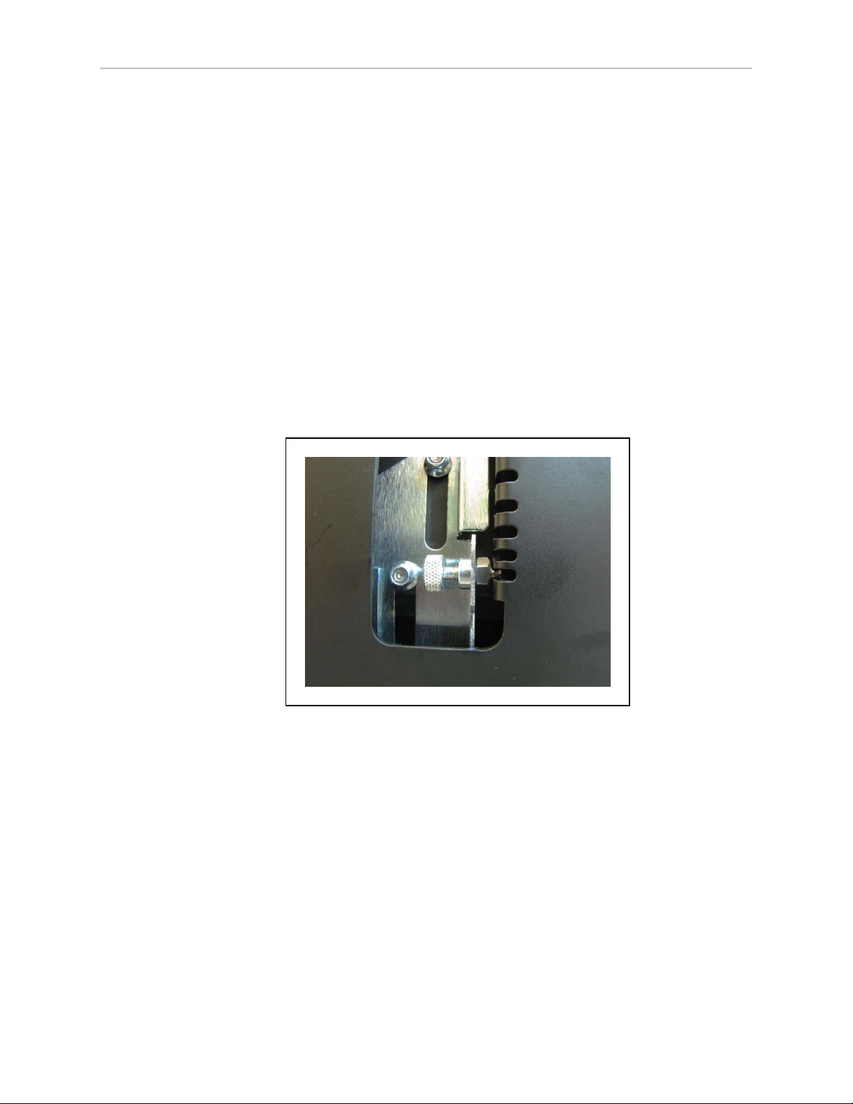
Docking Station Contact Adjustment
The contacts on the docking station have five height settings. The station is shipped with the
height in the middle setting, which should be correct in most cases. The height can be changed
by tilting the station enough to see the bottom of the base, making the adjustment accessible.
NOTE:Squeeze and keep the docking station foot against the bottom of the docking
station to make this adjustment easier.
Adjust the height of the contacts by using the pull-knob on the bottom of the dock. The height
changes by 4 mm (0.15 in.) for each notch. See the following figure.
The height of the contacts should be set so that the roller is high enough to stay in contact with
the platform as it is docking, but low enough so that the bi-level of the roller guides the paddle
under the platform.
Figure 3-24. Docking Station Contact Adjusting Pull-Knob
3.5 Installing the Cart Brake Release
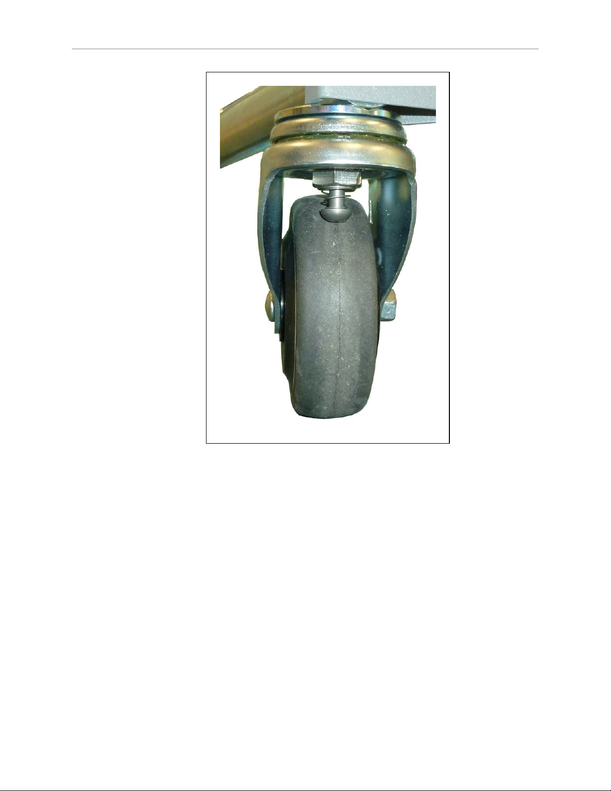
The two rear casters of the cart have brakes, which push a blunt pin against the caster rolling
surface to prevent the cart from rolling when it is parked on a floor that is not perfectly level.
LD Cart Transporter User's Guide, 14766-000 Rev B
Page 55 of 190
Page 56
Chapter 3: Setup
Figure 3-25. Cart Caster Brake, Showing Spring and Pin
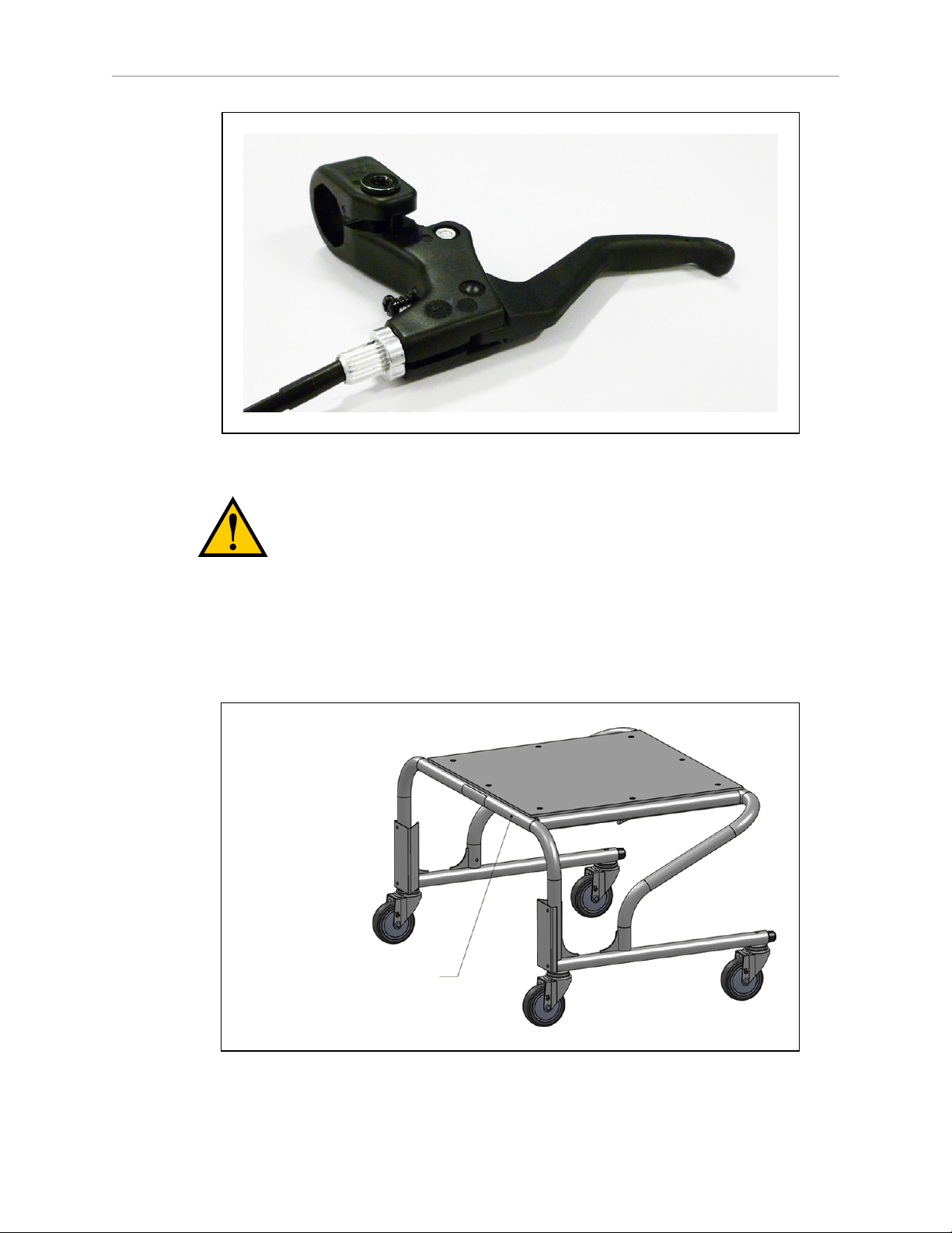
To allow an Operator to release the cart brakes when there is no cart transporter present, each
cart comes with a brake-release cable and lever, similar to a bicycle brake, that releases the cart
brakes when squeezed.
NOTE:The cart brake-release mechanism is actuated by the cart transporter when it
couples with the cart, so the cart will roll freely with the transporter. This part of the
brake release does not requires any user setup or adjustment.
Installation
The cart brake cable is attached on one end to the cart brake-release mechanism, and outfitted
on the other end with a bicycle-style brake lever, to release the cart’s brakes and allow an Operator to move the cart manually. It is up to the user to mount the brake-release lever at some location on the cart, and route the brake-release cable from the brake-release lever to the actuator.
The brake-release lever comes with a 1524 mm (60 in.) cable. The lever has a clamp the fits a
22 mm (7/8 in.) tube.
LD Cart Transporter User's Guide, 14766-000 Rev B
Page 56 of 190
Page 57
Chapter 3: Setup
Ø
0.25 Pass-through hole for brake
cable, through rear frame tube
Figure 3-26. Brake-release Lever
CAUTION: It is important that the brake-release handle be mounted in an
ergonomically-suitable location, so an Operator can repetitively release the
brakes without risking injury.
The actual mounting location and procedure for the brake-release handle are not covered here
due to the variability that is possible in cart structure designs. Ensure that no part of the cart
brake-release cable bends more than a 76 mm (3 in.) radius.
There is a 6.4 mm (0.25 in.) horizontal hole through the rear horizontal tube of the cart. See the
following two figures.
Figure 3-27. Thru-hole for Brake-release Cable
LD Cart Transporter User's Guide, 14766-000 Rev B
Page 57 of 190
Page 58
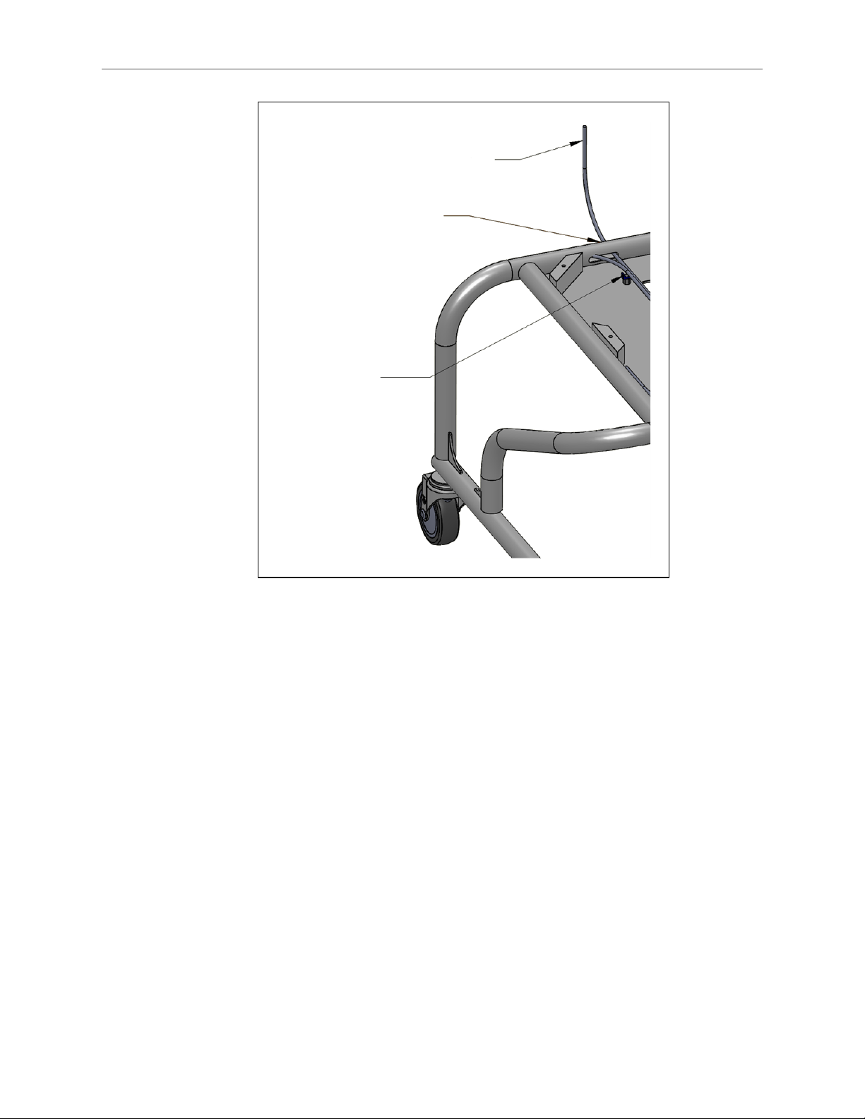
Chapter 3: Setup
Secure brake-release
cable to saddle tie
Ø 0.25 in. hole
through rear tube wall
Route brake-release
cable up to brake lever
After the brake-release lever has been mounted on the cart payload:
1.
Push the free end of the lever cable through the hole in the cart’s upper-rear horizontal
tube.
Figure 3-28. Thru-holes for Brake-release Cable, Plate Removed
LD Cart Transporter User's Guide, 14766-000 Rev B
Page 58 of 190
Page 59
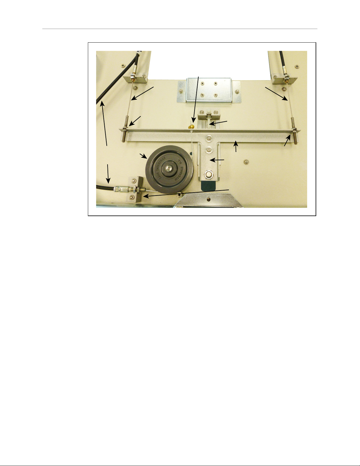
Chapter 3: Setup
Lever
Cable
Clamp
Lever
Cable
Actuator Bar
Hard Stop
Right
Brake
Cable
Left
Brake
Cable
Pulley
Lever Cable Anchor
Left
Brake
Adjust.
Right
Brake
Adjust.
Actuator
Bar
Figure 3-29. Internal Brake-Release Mechanism
2.
Route the cable to the lever cable anchor.
3.
Attach the actuator end of the cable to the lever cable anchor.
4.
Run the inner wire of the cable around the pulley, through the bushing in the actuator
bar, and through the lever cable clamp.
5.
Pull the inner wire tight enough to remove slack, and tighten the lever cable clamp on
it.
6.
Cut off the excess inner wire, leaving a small amount protruding past the clamp.
7.
Make a service loop of any excess lever cable, at least 152 mm (6 in.) in diameter.
8.
Adjustment
Attach the lever cable housing to the saddle tie. See Figure 3-28.
The brake lever cable needs to be adjusted so there is no excess slack, but so the brakes are
engaged when the lever is not being actuated. The two caster brake cables will be adjusted at
the factory.
Brake Lever Cable
The brake lever cable should be adjusted at the lever cable clamp, shown in the prededing figure. There should be just enough slack so the actuator bar touches its hard stop.
LD Cart Transporter User's Guide, 14766-000 Rev B
Page 59 of 190
Page 60

Chapter 3: Setup
Caster Cables
These should be adjusted correctly from the factory. If any adjustment is needed, refer to the
preceding figure for the adjustment location. The brake pins should be able to go down as far
as the caster surface allows, without any slack. The jam nuts on the two brake adjustments
should be installed using a threadlocker.
Actuator Bar Hard Stop
After the caster cables are adjusted correctly, ensure that the actuator bar just touches its hard
stop. This will keep the actuator bar in position if you have to adjust the lever cable.
LD Cart Transporter User's Guide, 14766-000 Rev B
Page 60 of 190
Page 61

Chapter 4: Configuration
The LD Cart Transporter comes with firmware and on-board software installed.
Configuration of an LD Cart Transporter is done using the MobilePlanner software. Configuration includes generation of the map that the robot will use for navigation. The cart parking goals need to be added to that map. This manual only provides an overview of that
process, which is covered in detail in the Mobile Robot Software Suite User's Guide.
CAUTION: The MobilePlanner dongle, which contains the license for running
the software, should be locked up when not in use, to prevent unauthorized
modifications to your system configuration. The software should be turned off
when not in use.
Other setup, mostly for communication, is handled by the SetNetGo OS, which is accessed
through the MobilePlanner software. It can also be accessed through a direct connection, so
your IT support can set up your wireless without needing the MobilePlanner license.
The transporter navigates using a map, generated with the MobilePlanner software. The operation of this software, as well as the downloading of the resultant map to the platform, is
covered in the Mobile Robot Software Suite User's Guide.
NOTE:The map must be generated and downloaded to the platform before you can
perform the steps covered in this chapter.
By default, the robot core, safety scanning laser, and some auxiliary power start automatically
when you press ON.
4.1 Settings and Configuration
Maintenance Ethernet Connection
To prepare your robot for autonomous mobile operation, attach a PC to the platform’s Maintenance Ethernet port, and connect with the SetNetGo OS through the MobilePlanner SetNetGo
interface. If you do not have wireless yet, you can connect MobilePlanner through the wired
Ethernet port (Maintenance LAN) and set up the wireless network later.
The robot core is preset and tested on a Class-C network (netmask for all ports 255.255.255.0).
The Maintenance Ethernet port is set to IP address 1.2.3.4 and the wireless IP comes set with
an AP-based (”managed”) SSID of “Wireless Network”, unsecured. Consult with your network
systems administrator before modifying these network details through the SetNetGo OS.
The User LANport is set to IP address 10.10.10.10.
Refer to the Mobile Robot Software Suite User's Guide.
The Maintenance Ethernet port is on the left side of the platform, under the small access panel
at the upper-right corner of the platform. (The joystick port is also there.) The access panel is
held in place with a push-push latch, and retained by a lanyard. See Figure 10-3. This is
internally connected to the Ethernet port located on the rear side of the robot core in the payload bay.
LD Cart Transporter User's Guide, 14766-000 Rev B
Page 61 of 190
Page 62

Chapter 4: Configuration
The Maintenance Ethernet port is permanently set to IP address 1.2.3.4, with a netmask of
255.255.255.0, for direct, wired access to the onboard systems. Accordingly, when accessing the
port, manually set the offboard computer’s Ethernet to an IP 1.2.3.x, where x is any number 1
through 254 except 4, and with a netmask of 255.255.255.0. No special DNS or gateway settings are needed.
Attach a pass-through or cross-over CAT5 (or better)Ethernet cable between the PC and the
Maintenance Ethernet port of the platform. The platform Ethernet is Auto-MDIX, and will
detect the type of cable you are using.
Start the Network Connections:Local Area Connection dialog for the ETH 0 Ethernet port:
(Windows) Start > Settings > Network Connections > Local Area Connection
Select Properties, and, from its dialog, scroll to and double-click the Internet Protocol (TCP/IP)
option. In the Internet Protocol (TCP/IP) Properties dialog, click both ‘Use the following…’ associated radio buttons to enable them, and then type in the IP and netmask values.
Setting Up Wireless Ethernet
The SetNetGo OS is used to configure the platform wireless Ethernet, among other things. Refer
to the Mobile Robot Software Suite User's Guide for details.
NOTE:Although an LD Cart Transporter is capable of working without wireless
Ethernet if there are no other LD Cart Transporters that it needs to know about (and
to avoid), that is the exception. In most cases, wireless Ethernet will be needed.
NOTE:For all of the following settings, work with your IT group to verify the correct IP, radio, and security settings.
The following applies to the wireless Ethernet supported by the platform.
The SetNetGo OS is used to configure the wireless Ethernet, among other things. Refer to the
Mobile Robot Software Suite User's Guide for details.
Access the SetNetGo OS through the MobilePlanner software:
MobilePlanner >SetNetGo >Network
NOTE:It is also possible to connect directly to the SetNetGo OSon a platform
through a web browser. The main intent of this is to allow your IT support to set up
the network for you, without using MobilePlanner, which requires a license.
IP Address, Netmask, Gateway, DNS1
Choose Static (DHCP is not recommended), and fill in the IP address, netmask, gateway, and
DNS1, as supplied by your network administrator.
NOTE:The following settings have to be provided by your IT department.
Radio Settings
l
SSID (e.g. AGV)
Fill in the appropriate wireless SSID for your wireless network.
The SSID is case sensitive.
LD Cart Transporter User's Guide, 14766-000 Rev B
Page 62 of 190
Page 63

l
Mode
Managed/STA, Ad-Hoc, or Master/AP
l
Radio Mode
Auto, 802.11a, 802.11b, 802.11g
l
Channel Set
l
Wireless Watchdog IP Address
l
Wireless Watchdog Max Count
0 disables this.
Security Settings
Encryption:
l
Disabled
l
WEP 64-bit
l
WEP 128-bit
Chapter 4: Configuration
l
TKIP/RC4
l
CCMP/AES
l
TKIP/CCMP/AES
Authentication:
l
OPEN
l
WPA-PSK
l
WPA2-PSK
WEP
l
WEP Key Number (Key 1 - Key 4)
l
WEP Keys
WPA/WPA2-PSK
l
PSK
l
PSK-Type (Passphrase or Raw Hex)
Click Apply for your changes to take effect.
Wireless Coverage
The robot must have wireless coverage for multi-robot installations, or in areas where you
wish to send new commands to or receive status updates from the robot.
Ensure that, in such cases, you have adequate wireless coverage. Because of the variation possible in different environments, we don't specify what components or techniques should be
used to obtain this coverage.
LD Cart Transporter User's Guide, 14766-000 Rev B
Page 63 of 190
Page 64

We suggest that you conduct a comprehensive site survey to ensure adequate wireless coverage. You can test the coverage of your wireless setup by trying to ping it from various locations.
>= -40 dBm is the ideal WiFi signal strength, -60 dBm is the recommended minimum.
Bandwidth Considerations
The typical bandwidth in a fleet will average about 50 Kbps/AIV. This would increase if the
robot is connected to the Enterprise Manager 1100, and is actively viewed by MobilePlanner.
This number can increase or decrease depending on the types of commands and debugging
tools that are enabled in MobilePlanner. In any case, the bandwidth is not likely to exceed 500
Kbps per robot (0.5 Mbps).
0.5 Mbps per robot would easily fit within the capabilities of access points (>=54 Mbps). If you
have multiple access points, this number becomes even less of a concern.
4.2 Mapping
There are many options for configuring and tuning your transporter to best suit your application.
In order to have your LD Cart Transporter perform autonomous mobile activities, you need to
make a map of its operating space. Configuration includes generation of the map that the LD
Cart Transporter will use for navigation. The cart parking goals need to be added to that map.
Use the MobilePlanner application to make the map. This manual only provides an overview
of that process, which is covered in detail in the Mobile Robot Software Suite User's Guide.
Chapter 4: Configuration
Maps may contain a variety of virtual elements which act to modify the behavior of an robot.
Virtual elements include forbidden lines and areas, speed zones, preferred-direction zones, and
more, all working to help you configure your workspace for efficient and safe performance of
your mobile application. You can also create your own virtual elements for application-specific
robot-workspace interactions.
Maps contain a variety of goals, routes, and tasks that comprise the destinations and activities
of the robot in the workspace. There needs to be a goal at every location where you want the
transporter to be able to pick up or drop off a cart. Make sure that the goal orientations leave
room for the platform to maneuver.
The tasks involved are:
l
Make a floor plan scan while driving the cart transporter with the joystick.
l
Load that floor plan scan into MobilePlanner, on your PC, to make and edit the map.
l
Add goals and docks to your map. In particular, refer to:
Working With Map Files > Editing a Map File >
Using the Drawing Tools > Adding Goals and Docks
in the Mobile Robot Software Suite User's Guide.
l
Transfer the working map to the Enterprise Manager 1100, or back to the platform, if
you have only one platform, to perform autonomous mobile actions.
The Enterprise Manager will automatically download the new map to each robot in
your fleet as soon the robot becomes idle.
LD Cart Transporter User's Guide, 14766-000 Rev B
Page 64 of 190
Page 65

Chapter 4: Configuration
l
If you have multiple, separate working spaces, which will each require their own map,
you can save map collections and deploy your platform in any of your working spaces
by selecting the appropriate map file.
NOTE:It is a good idea to have the automated docking station installed prior to creating the map scan. Its distinctive diagonal face will be useful in locating and setting it up in the map.
Setting Up Cart-Parking Goals
Any location where you want a cart to be picked up or dropped off needs to have a corresponding goal on the map. Pay special attention to the direction of the goals, as the transporter may need extra room to maneuver into the correct position for coupling.
Marking Cart-Parking Goals on Floor
The purpose of marking the parking goals on your floor is so that a human being knows
where to leave a cart, so that the transporter will find it and be able to couple with it.
Even if people will never be moving carts, this step is recommended, so that someone doesn’t
place other items where a cart needs to be parked.
If people will be moving carts, make sure that your markings include the direction of the goal,
so the transporter will be approaching from the correct direction.
The easiest way to accurately mark the goals where a cart may be parked is to send the transporter to each cart-parking goal, and, while the transporter is at the goal, put down tape markings that include the size of the cart, as well as the transporter‘s orientation. The transporter
will always approach the goal from the same direction, so the cart needs to be oriented correctly.
4.3 Configuring a Touchscreen
You configure the touchscreen's appearance and behavior with the MobilePlanner software.
The tasks include setting the mode to use, setting up goals for relocalization, and specifying a
custom screen logo and the language to be used for the display.
Touchscreen Ethernet Setup
The touchscreen plugs into the UserLAN port on the platform‘s core.
NOTE:After making and saving changes within User LANEthernet Settings, the
platform has to be power-cycled for those changes to take effect. If the only change
is to enable DHCP, then the platform does not have to be power-cycled.
In the MobilePlanner software, select:
MobilePlanner > SetNetGo
Network > User LAN Ethernet
LD Cart Transporter User's Guide, 14766-000 Rev B
Page 65 of 190
Page 66
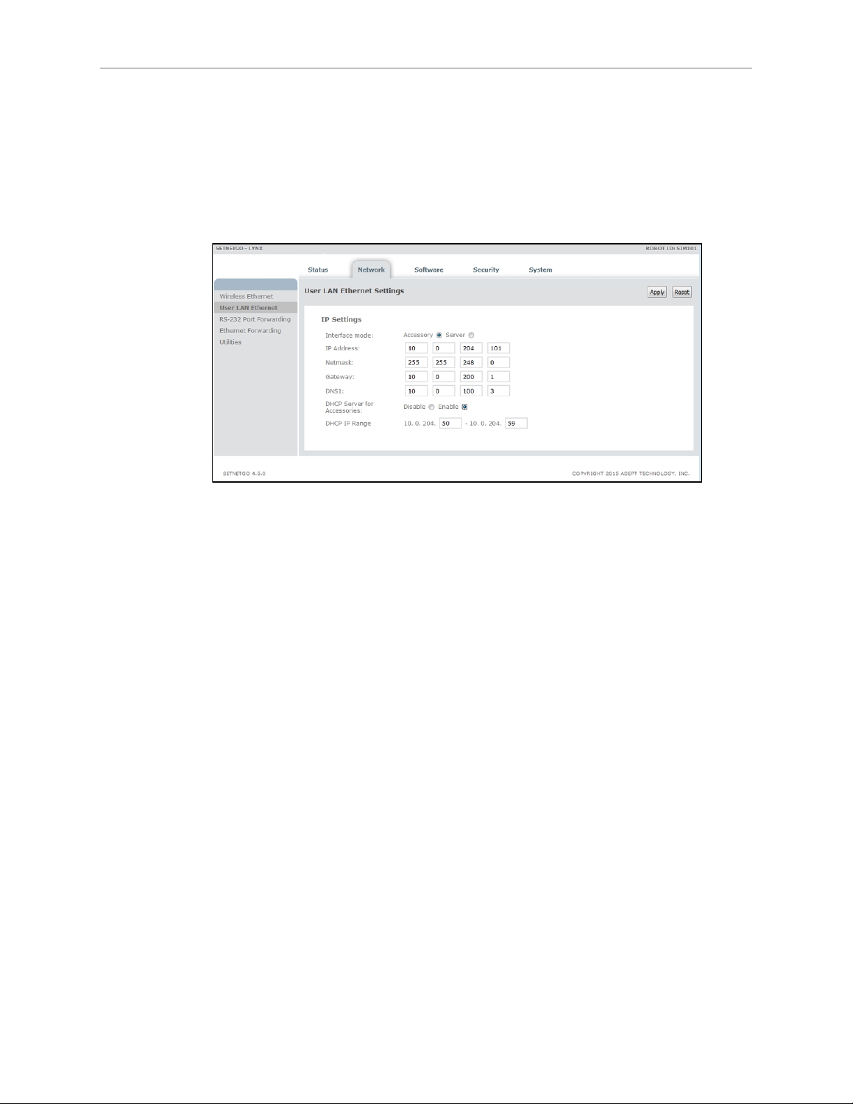
Ensure that:
l
the IP address subnet doesn’t conflict with the Wireless Ethernet IP subnet
l
Interface mode is set to Accessory
l
DHCP Server for Accessories is set to Enable
l
DHCP IP Range is large enough to provide IP addresses for all connected devices
Chapter 4: Configuration
Figure 4-1. Accessory and DHCP Server for Accessories Enabled
Operating Modes
Specify the touchscreen mode: either Choose Dropoff or Patrol Route.
l
Choose Dropoff mode allows the Operator to input the next dropoff goals.
l
Patrol Route mode simply drives around a specific route. The robot will have goals that
it stops at, but the Operator will not be able to alter the order of those goals.
For Choose Dropoff, you specify how many dropoff buttons there will be, and how each button
is labeled, as well as the goal on the robot's map that gets associated with each button.
For Patrol Route, you specify the name of the route and whether to start the patrol on bootup.
The route will include whatever goals the robot will stop at, and how long it will wait at each
specific goal.
These parameters are accessed from:
MobilePlanner >Config, then Robot Interface >Touchscreen
Select either Choose Dropoff or Patrol Route with the Pages >MainPage parameter, which has
a dropdown selection box.
Choose Dropoff Mode
The following parameters only apply to the Choose Dropoff mode.
Dropoff Priority
This is accessed under Pages >ChooseDropoffPage.
LD Cart Transporter User's Guide, 14766-000 Rev B
Page 66 of 190
Page 67

Chapter 4: Configuration
You can enable high-priority dropoffs, which will be serviced before normal-priority dropoffs.
The Operator can specify that a goal is high-priority when it is being selected for the upcoming
dropoff.
AllowHighPriorityDropoffs
This allows some dropoffs to be specified as high-priority. This is enabled by
default, and you can disable or re-enable it in the MobilePlanner software.
HighDropoffPriority
This is the priority assigned to any dropoff that is specified as high-priority.
Higher priority jobs will be serviced before lower-priority jobs by the queuing
manager. This has no effect if AllowHighPriorityDropoffs is disabled.
Dropoff Buttons
This is accessed under Pages >ChooseDropoffPage.
DropoffButtonCount
This specifies the total number of buttons that will be available on the touchscreen page. You can scroll the page to see other buttons, if all of the buttons cannot be displayed at once.
DropoffButtonx
There will be a DropoffButton1 through DropoffButtonx, where x = DropoffButtonCount. Each contains the two following parameters:
GoalName
This is a combo box that lists all of the goals that have been created
on the map. Select the map goal to be serviced when this dropoff
button is pressed.
You can eliminate a button from the screen by making GoalName
blank. The other buttons will fill in, so there will be no blank spaces
in the screen.
ButtonLabel
This is the text label displayed on the dropoff button. If empty, the
GoalName is displayed.
Patrol Route Mode
NOTE:A goal can have a wait time associated with it,
to give an Operator time to load or unload the robot.
This is configured, in the map, using the MobilePlanner
software.
The following parameters only apply to the Patrol Route mode.
In this mode you need to specify the name of the Patrol Route that the robot will patrol. The
route needs to have already been set up using the MobilePlanner software. You also need to
specify if the robot will start its patrol automatically, or if it requires an Operator to press Go.
LD Cart Transporter User's Guide, 14766-000 Rev B
Page 67 of 190
Page 68

Chapter 4: Configuration
Select Pages >PatrolRoutePage
l
In RouteName, enter the route to be patrolled.
l
Check AutoStartRoute for the robot to start its patrol as soon as the Patrol Route screen
is displayed (the touchscreen has finished booting).
Localization Goals
You need to configure at least one localization goal. You can configure more if you want. A localization goal is needed to relocalize a lost robot from the touchscreen.
Each localization goal should have:
l
a heading
The robot will need to be aligned with the heading when relocalizing.
This applies to both laser and Acuity localization.
l
mapped features that don’t change much
Things that get moved frequently, such as pallets, chairs, or carts do not make good
mapped features, because the map will not match what the laser is seeing.
l
mapped features that don’t get blocked
If a mapped wall is often used for stacking boxes or storing carts, the laser may have
trouble seeing the wall behind those objects.
l
multiple visible lights, when using Acuity localization
The more lights the robot can see, the better.
l
a high localization score
This represents the percent of readings that the robot currently sees that match the features on its map.
NOTE:Localization goals do not have to be dedicated to localization - they can
also be used as normal goals for regular use.
In MobilePlanner, select:
Config > Robot Interface > Touchscreen
From there, use ChooseLocalizationPage to set LocalizationButtonCount to the number of localization goals you want, and then specify the GoalName and ButtonLabel for each.
LD Cart Transporter User's Guide, 14766-000 Rev B
Page 68 of 190
Page 69
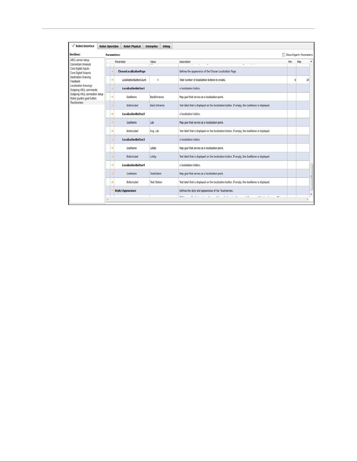
Chapter 4: Configuration
Figure 4-2. Localization Goal Parameters
Screen Logo
In MobilePlanner, select
Config > Robot Interface > Touchscreen
From there, use Style/Appearance.
A logo is displayed in the upper-left corner of the touchscreen. The default logo is Omron, as
shown in the following figure.
LD Cart Transporter User's Guide, 14766-000 Rev B
Page 69 of 190
Page 70
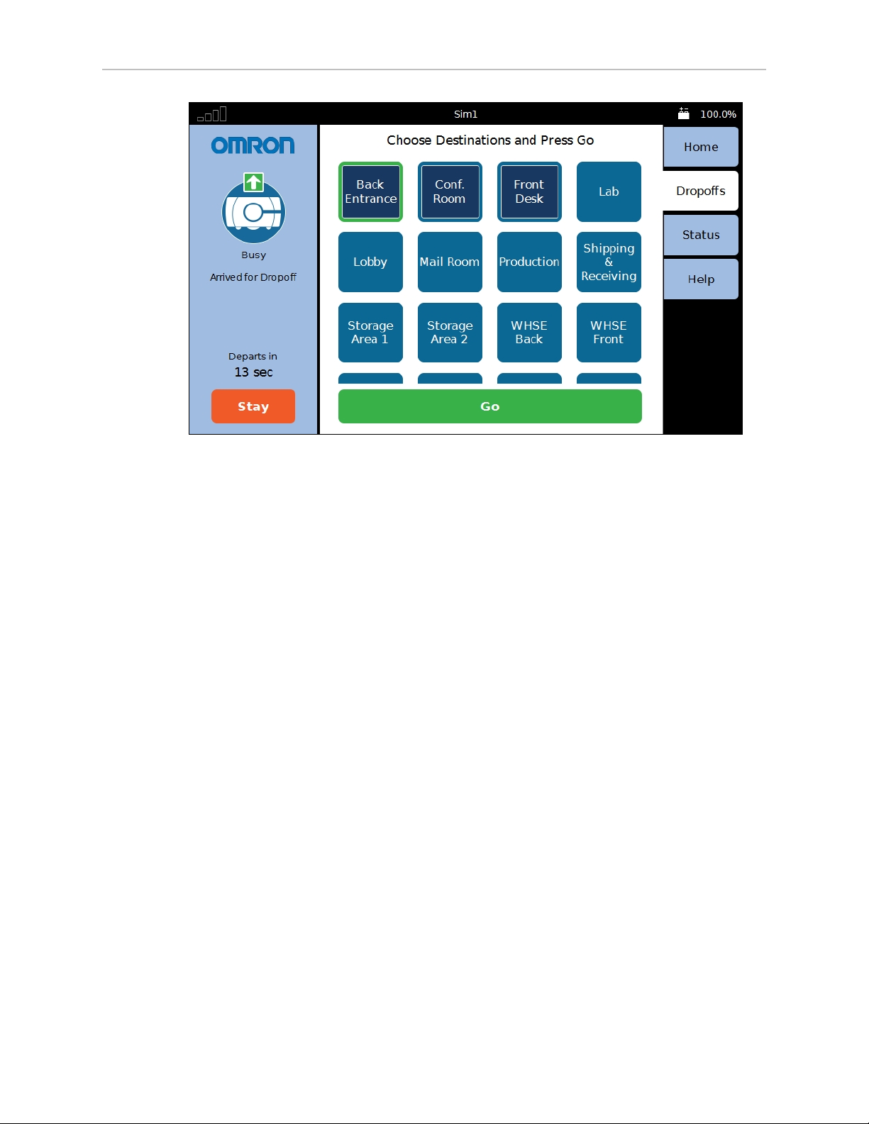
Chapter 4: Configuration
Figure 4-3. Sample Touchscreen, with Omron Logo, in Choose Dropoff Mode
You can customize this with a logo of your choosing using the following steps:
1.
Upload a PNG image file to the robot using the MobilePlanner software:
File > Download/Upload
2.
Open the robot Configuration window and choose:
Robot Interface > Touchscreen
3.
Edit the SmallLogo parameter.
a.
Click the file-select button to open the file chooser.
b.
Select the newly-uploaded file.
c.
Click Open.
4.
Click Save, to save the configuration.
NOTE:If the SmallLogo field is left blank, the default Omron logo will be displayed.
NOTE:If a different version of the same file name is uploaded to the robot, you will
need to power cycle the robot to see the change.
Screensaver
In MobilePlanner, select
Config > Robot Interface > Touchscreen
From there, use Screensaver.
LD Cart Transporter User's Guide, 14766-000 Rev B
Page 70 of 190
Page 71

Chapter 4: Configuration
If the robot is in motion when the screensaver comes on, it will use the Busy icon, and display
a status message (where it’s going). If the robot is not in motion, it will display the Available
icon. The rounded rectangle, icon, and any text inside the rectangle will move around the
touchscreen display area.
Screensaver Enabled
This is a checkbox that determines whether a screensaver is displayed when the touchscreen is
inactive. Checking the box enables the screensaver.
TimeoutSeconds
This is the number of seconds that will elapse before the screensaver is turned on. This has no
effect if the Screensaver Enabled box is not checked. The range is 1 - 999 seconds.
StayOnTouch
This is a checkbox that determines if touching the screensaver has the same effect as touching
Stay. If this is checked, the robot will stay when the screensaver is touched.
Display Language
You can select what language is used for the display from a dropdown box in the MobilePlanner software.
NOTE:Some messages from the robot will be in English, regardless of the language
set here. These include status and mode messages.
From MobilePlanner, select:
Config > Robot Interface >Language/Location
Select RobotLanguage, which has a dropdown selection box.
This parameter is not touchscreen-specific, so it may affect other displays that involve written
language. As of this writing, only the touchscreen is affected. This parameter does not affect
synthesized speech.
LD Cart Transporter User's Guide, 14766-000 Rev B
Page 71 of 190
Page 72
Contact Information
Chapter 4: Configuration
Figure 4-4. Help Screen, with Contact Information
Help shows installed software and contact information.
NOTE:No contact information will be displayed unless it is set up in the
MobilePlanner software.
In MobilePlanner >Config:
l
Robot Interface >Touchscreen >ContactInformation
l
Check the ShowContactPage checkbox.
l
Enter appropriate information in ContactName and the fields following it.
4.4 Acceleration, Deceleration, and Rotation Limits
Reducing the absolute max allowable linear and rotational acceleration, deceleration, and
speed will affect the size of the allowable CG envelope, but it may do so in non-obvious ways.
For use-cases where the payload can’t be decreased, or the CG can’t be brought within the
recommended limits, Service can work with your system designer to input your needs into our
models.
Contact Omron Adept Technologies, Inc. for details. See Support on page 17.
If your payload’s center of gravity is not within the guidelines given in the Payloads chapter,
you will need to adjust the Absolute Movement Maximums parameters in the MobilePlanner
software.
From the MobilePlanner software, Config:
LD Cart Transporter User's Guide, 14766-000 Rev B
Page 72 of 190
Page 73
Chapter 4: Configuration
Robot Physical >Absolute Movement Maximums
Show Expert + Parameters needs to be checked to see or modify these parameters.
The first two parameters and AbsoluteMaxRotVel are not likely to have significant impact on
the robot‘s stability. The Accel and Decel parameters will have a major impact. In certain
cases, if the payload is lopsided, the AbsoluteMaxRotVel may need to be adjusted.
The limits and defaults for these parameters are listed in the following table.
Parameter Default Min Max
AbsoluteMaxTransVel (LD-105CT) 1300 1 2500
AbsoluteMaxTransVel (LD-130CT) 900 1 2500
AbsoluteMaxTransNegVel -250 -2500 -1
AbsoluteMaxTransAccel 500 1 2000
AbsoluteMaxTransDecel 500 1 2000
AbsoluteMaxRotVel 100 1 180
AbsoluteMaxRotAccel 180 1 360
AbsoluteMaxRotDecel 180 1 360
4.5 Supplemental Information
Laser Setup
For most installations, the defaults for the lasers should be appropriate, and will not require
any user adjustment.
The specific parameters for these lasers will come in the model config file that ships on the
unit, or can be provided on request if needed.
l
Laser_1 Settings are for the main scanning laser (S300), used both for safety and localization.
l
Laser_2 Settings are for the low front laser (TiM).
l
Laser_3 Tilted and Laser_4 Tilted are for the side lasers (TiM).
l
Laser_5 Settings are for the coupling laser (TiM).
l
Laser_6 Settings are the rear-facing laser (TiM).
LD Cart Transporter User's Guide, 14766-000 Rev B
Page 73 of 190
Page 74

Page 75

5.1 Safety
Drive Warning Light
For CE compliance, a mobile robot is required to have a readily-visible warning light, when it
is either ready to move or is moving. The platform comes with light discs on each side, and
the HMI post has a beacon, designed to be higher than a normal payload, to do this.
If you have a payload that blocks the beacon, the core also provides an output, so you can add
your own warning device. This may be necessary for taller payloads, which may make the
beacon not always visible. The core has a Light Pole connector, which is covered in the Connectivity chapter in Robot Core Rear, Upper on page 97. This can be used to drive a warning
light in a more prominent location for taller payloads.
Turn Warning Lights
A mobile robot is also required, for CE compliance, to have readily-visible turn warning lights,
when it is either turning or about to turn. The platform’s light discs indicate that the robot is
turning, and in which direction.
If you have a payload that blocks the beacon, the core also provides an output, so you can add
your own warning device. This may be necessary for taller payloads, which may make the
beacon not always visible. The core has a Light Pole connector, which is covered in the Connectivity chapter in Robot Core Rear, Upper on page 97. This can be used to drive a warning
light in a more prominent location for taller payloads.
Chapter 5: Payloads
5.2 Considerations
Dimensions
You must keep your payload no wider and no longer than the cart.
Take care to keep all of the sensors exposed. If any of the sensors get blocked, the robot won't
be able to function as intended. This is critical in the case of the lasers.
The payload design must not obstruct the side lasers' field of view.
If you have Acuity localization, you need to make sure that the height of your payload does
not obstruct the camera’s field-of-view. The Acuity camera lens has a 140° field-of-view, so
take care that nothing higher than the camera lens is close beside the camera.
Pinch Hazard
There is a potential, with an improperly-designed cart payload, to create a pinch hazard
between the payload and the HMI post.
LD Cart Transporter User's Guide, 14766-000 Rev B
Page 75 of 190
Page 76

Chapter 5: Payloads
CAUTION: Potential pinch hazard. Ensure that there is enough space between
the HMI post and your payload, when the transporter and cart are coupling,
that it is not a pinch hazard.
Weight
Run-time between charges is a function of payload weight. A heavier payload will result in a
shorter run-time. If you have added any options to the transporter that draw power from the
transporter battery, that will also result in decreased run-time.
Center of Gravity
When adding payload, the center of gravity of the entire cart and payload needs to be considered.
As much as possible, you should keep the payload center of gravity centered on the cart, and
as low (close to the platform top) as possible. This will give you the best stability, particularly
when turning or crossing irregularities in the floor.
The payload should be centered on the cart left-to-right, but biased toward the rear of the cart
according to the following plots.
The following figures show the calculations of safe placements for the center of gravity for payloads with the weights listed. The center of gravity, in each instance, needs to be within the
area shown. All units are mm.
WARNING: These figures show centers of gravity for the listed parameter settings only. They do not apply to any other parameter settings. Even small
changes in these parameters can change the safe CG area drastically.
LD Cart Transporter User's Guide, 14766-000 Rev B
Page 76 of 190
Page 77
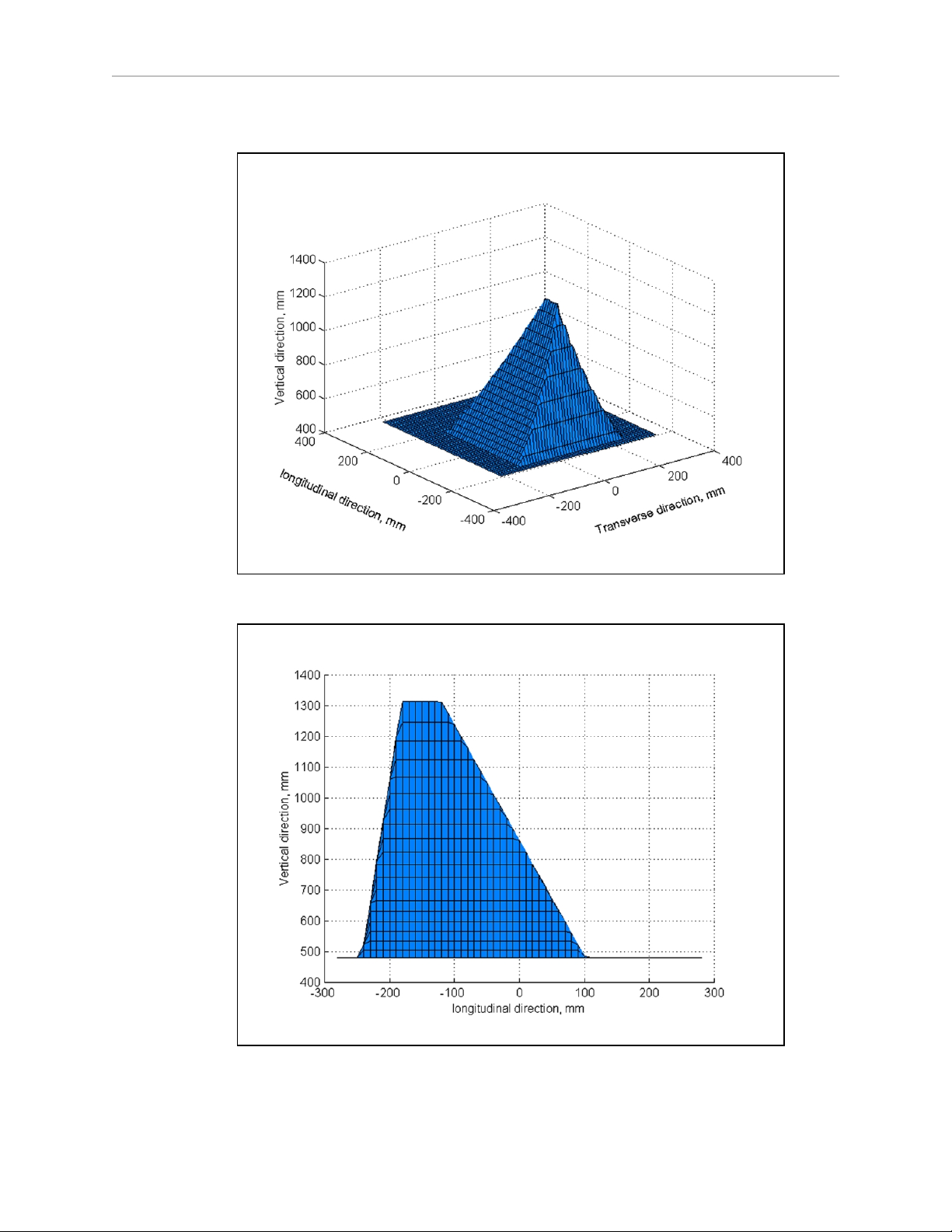
105 kg
Chapter 5: Payloads
Figure 5-1. Isometric View, 105 kg
Figure 5-2. Longitudinal View, 105 kg
LD Cart Transporter User's Guide, 14766-000 Rev B
Page 77 of 190
Page 78
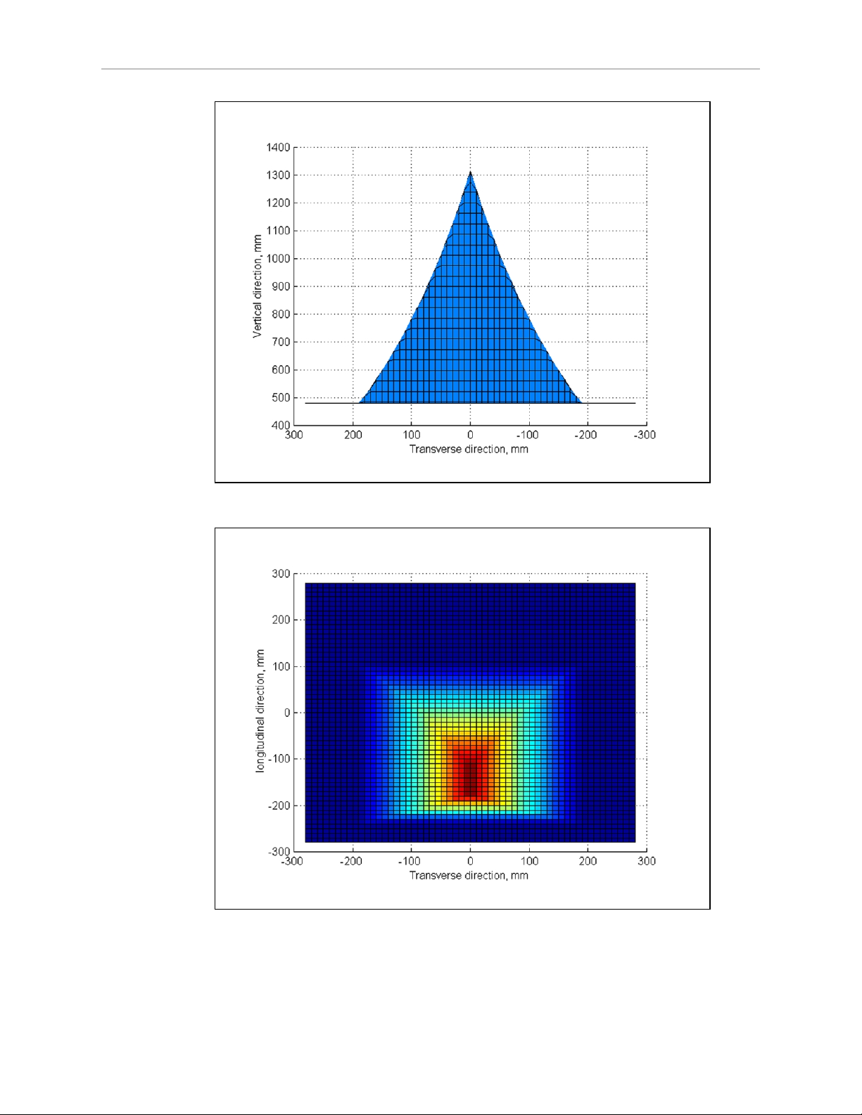
Chapter 5: Payloads
Figure 5-3. Transverse View, 105 kg
Figure 5-4. Top View, 105 kg
LD Cart Transporter User's Guide, 14766-000 Rev B
Page 78 of 190
Page 79
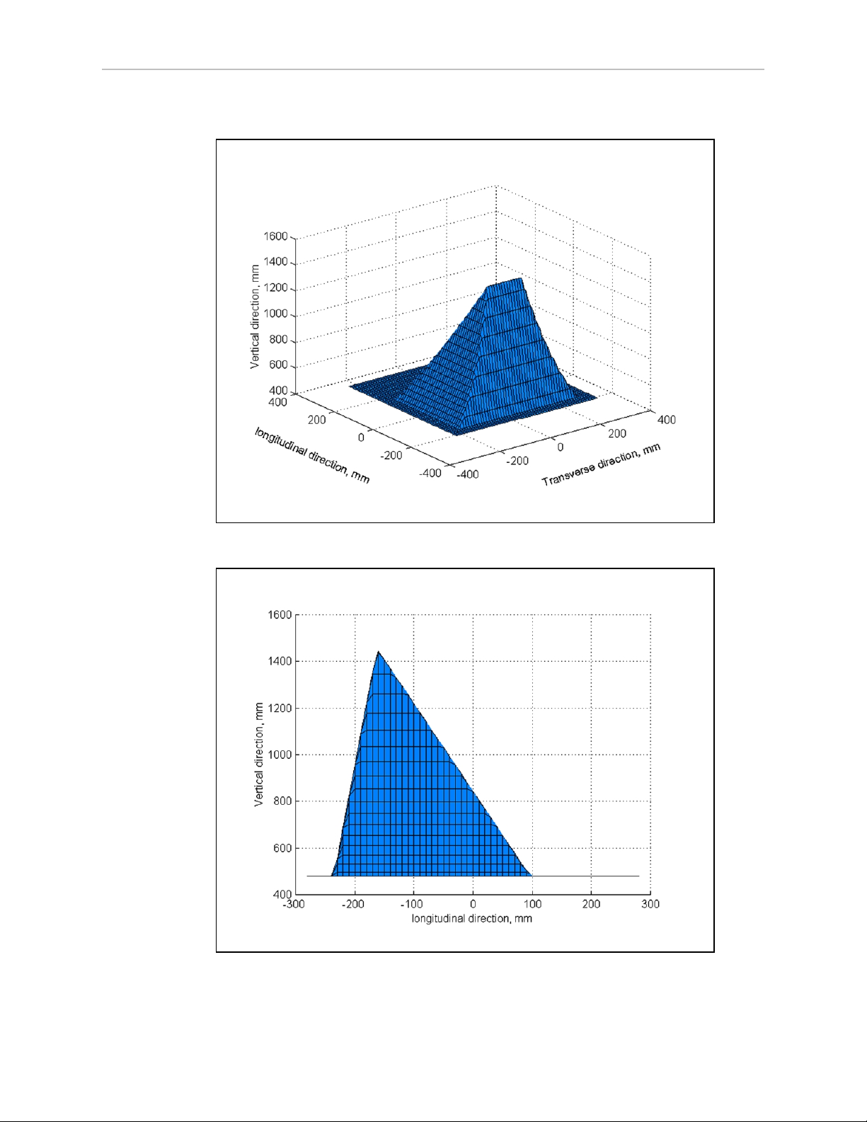
130 kg
Chapter 5: Payloads
Figure 5-5. Isometric View, 130 kg
Figure 5-6. Longitudinal View, 130 kg
LD Cart Transporter User's Guide, 14766-000 Rev B
Page 79 of 190
Page 80
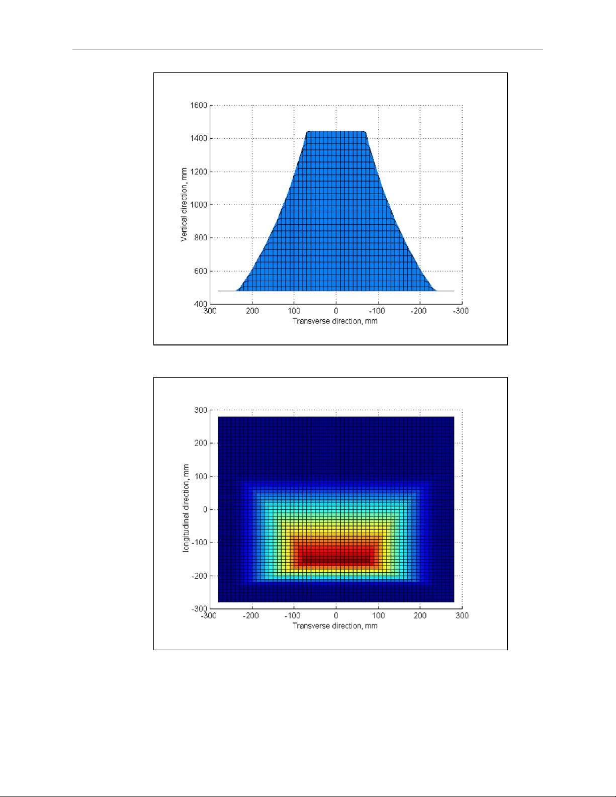
Chapter 5: Payloads
Figure 5-7. Transverse View, 130 kg
Figure 5-8. Top View, 130 kg
LD Cart Transporter User's Guide, 14766-000 Rev B
Page 80 of 190
Page 81

Chapter 5: Payloads
5.3 Payload-Related Tradeoffs
If you have to extend your center of gravity beyond the guidelines given here, you will need to
adjust various parameters in the MobilePlanner software to compensate for that.
Contact your robot provider to get a new set of plots based on parameters that differ from
those used to produce the plots shown here.
In general, lowering the maximum accel, decel, and rotation speeds will be required. Refer to
Acceleration, Deceleration, and Rotation Limits on page 72.
LD Cart Transporter User's Guide, 14766-000 Rev B
Page 81 of 190
Page 82

Page 83

Most of the connections that are available to the user are in the payload bay, which is the
space between the platform and the platform top plate. These include I/O and power connections. Access to the payload bay is covered in Accessing the Payload Bay on page 152.
For a cart transporter system, most of these connections will not usually be used.
The two connections outside of the payload bay are the Joystick port and the Maintenance Ethernet port, which are located under a small access panel on the left side of the platform, in the
upper-right corner. Both of these ports have a second, connected port inside the payload bay.
6.1 Required Connections
l
Joystick port In order to generate maps with the transporter, you need to connect a
joystick to its Joystick port.
The Joystick port is located under a small access panel on the left side
of the platform, in the upper-right corner.
This is internally connected to another Joystick port in the payload
bay.
l
Maintenance
Ethernet
The Maintenance Ethernet port is located under a small access panel
on the left side of the platform, in the upper-right corner.
Chapter 6: Connectivity
Its IP address is 1.2.3.4, with Netmask 255.255.255.0.
Access to the SetNetGo OS is always enabled on this interface, and
does not require a password or a license.
This is internally connected to another Maintenance Ethernet port in
the payload bay.
l
Wireless
Ethernet
For multi-robot installations, or where you wish to send new commands or receive status updates from the robot, you need to have wireless Ethernet.
l
Docking
Station
The robot needs access to a docking station so it can charge itself. The
docking station needs access to AC power.
6.2 LD Cart Transporter Connections
NOTE:All of these are in the payload bay.
NOTE:If a connection is covered in this subsection, it means that the description in
the subsection Standard Platform Connections on page 89 does not apply to the
transporter, because that connection is being used for a cart-specific use.
LD Cart Transporter User's Guide, 14766-000 Rev B
Page 83 of 190
Page 84

Core
Chapter 6: Connectivity
l
RS232-2 is used for the rear-sensing laser.
l
Both the Debug Port and Aux Power are used by the coupling laser.
l
Digital I/Oconnector.
The transporter uses pins 9 - 16, both Input and Output.
Pins 1-8 are available on the cart PCA.
l
User Power is used for cart PCA power.
l
User Interface goes through the PCA to the Operator panel.
l
Aux Sensors is used for both side lasers and the low front laser.
l
Light Pole goes through the PCA to the Operator panel.
l
User LAN goes to the Ethernet switch in the payload bay. Two ports are spares.
LD Cart Transporter User's Guide, 14766-000 Rev B
Page 84 of 190
Page 85
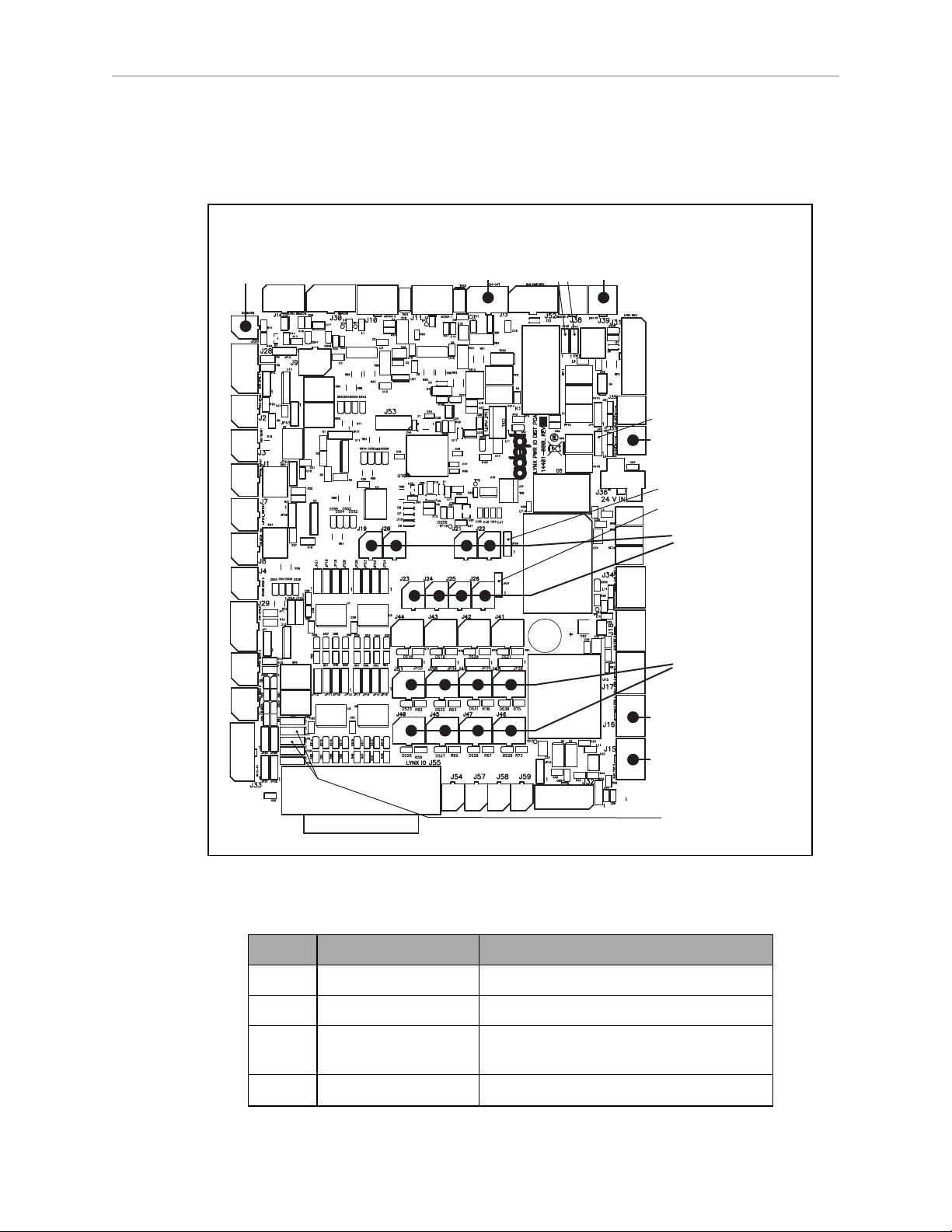
Cart-Specific PCA
J15
J16
User Power Out
User I/O Out 1 - 8
J19 - 26
User PowerJ37
User I/O In 1 - 8
J40, 45 - 51
User
Beeper Out
J56
User EMO Out
J13
User EMO Switch
Connector
J39
JP41JP40
JP5
JP26
JP27
JP6, JP7
NOTE:Contact Omron Adept Technologies, Inc. for details.
Chapter 6: Connectivity
User E_Stop (USER EMO OUT), J13. Micro MATE-N-LOK, mates with TE6C 794617-6.
Pin No. Designation Notes
1 ESTOP 2A Dry contact
2 ESTOP 2B Dry contact
3 BRAKE Use switch to connect to BATTERY (pin 5)
4 ESTOP CTRLD POWER (BAT) 1 A limit
Figure 6-1. PCA Silkscreen with Callouts
for external brake release
LD Cart Transporter User's Guide, 14766-000 Rev B
Page 85 of 190
Page 86
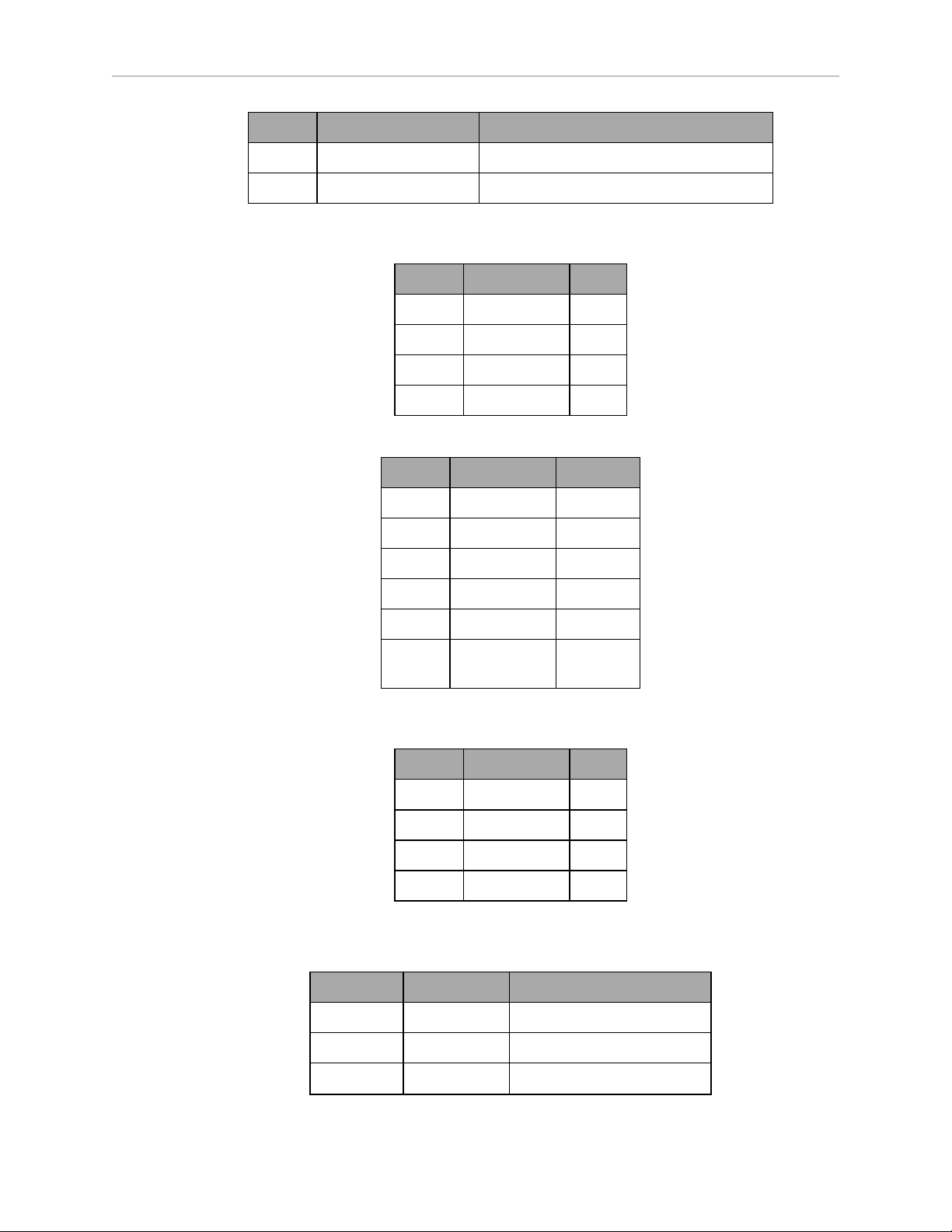
Chapter 6: Connectivity
Pin No. Designation Notes
5 BATTERY 1 A limit
6 GND
User E-Stop Switch (USER EMO SWITCH), J39. Jumpers JP40 and JP41 must be moved to pins
1-2 for this to be functional. MiniFit Jr™, mates with MOLEX 4C 39-01-2045.
Pin No. Designation Notes
1 ESTOP 1A
2 ESTOP 2A
3 ESTOP 1B
4 ESTOP 2B
User Power, J15 & J16. MiniFit Jr™, mates with MOLEX 6C 39-01-2065.
Pin No. Designation Notes
1 GND
2 GND
3 GND
4 5 V 2 A total
5 12 V 1.5 A total
6 BATTERY 22-28 V
1 A total
User Power, J37. Jumper JP5 selects battery (1/2) or E-Stop-controlled battery (2/3).
MiniFit Jr™, mates with MOLEX 4C 39-01-2045.
Pin No. Designation Notes
1 BATTERY 1.8 A
2 GND
3 N.C.
4 SHIELDGND
User I/OOutputs, J19 - J26. Micro MATE-N-LOK, mates with TE 2C 794617-2.
The return is common for each bank of four outputs, with the indicated jumper.
Connector Designation Notes
J19 OUT1 JP13, LEDDS14
J20 OUT2 JP11, LEDDS15
J21 OUT3 JP10, LEDDS16
LD Cart Transporter User's Guide, 14766-000 Rev B
Page 86 of 190
Page 87
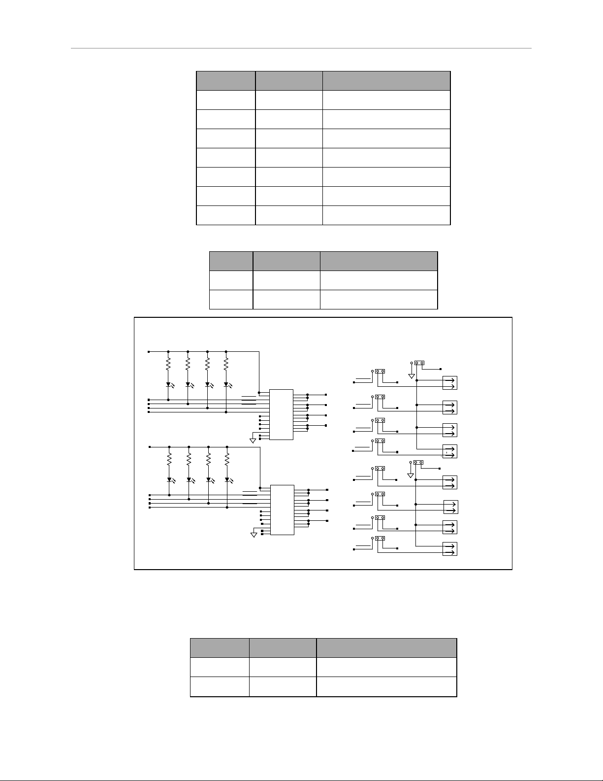
Chapter 6: Connectivity
123
123
123
123
1
123
123
123
123
123
1
1
1
1
2
J26
1
2
J25
1
2
J24
1
2
J23
1
2
J22
1
2
J21
1
2
J20
1
2
J19
VBAT
JP27
NC
NC
9.09K 9.09K 9.09K
9.09K
R60
9.09K
R61
9.09K
R58
9.09K
R59
IO_OUT_8
IO_OUT_4
6/D8,6/C1
NC
OUT_8
OUT_3
OUT_6
JP26
JP16
JP12
OUT_COM_5-8
OUT_7
6/C6
IO_OUT_7
IO_OUT_8
6/C6
JP17
JP14
OUT_1
IO_OUT_6
6/C6
IO_OUT_5
6/C6
6/D6
IO_OUT_4
6/D6
IO_OUT_2
IO_OUT_3
6/D6
6/D6
IO_OUT_1
6/D8,6/C3
IO_OUT_1
IO_OUT_5
IO_OUT_3
6/D5
6/D5
IO_OUT_1
IO_OUT_1
JP13
JP11
JP10
6/D8,6/C3
IO_OUT_3
IO_OUT_2
6/D7,6/C3
DS13
IO_OUT8
DS12
IO_OUT7
DS11
IO_OUT6
DS10
IO_OUT5
25
22
23
24
15
14
13
16
17
21
20
10
8
4
19
18
1
2
6
3
5
7
9
IO_OUT_7
6/C5
IO_OUT_8
NC
NC
6/C5
IO_OUT_7
IO_OUT_6
6/C5
IO_OUT_5
6/C5
IO_OUT_6
DS17
GRN LED
IO_OUT4
DS16
GRN LED
IO_OUT3
DS15
GRN LED
IO_OUT2
DS14
GRN LED
IO_OUT1
25
22
23
24
15
14
13
16
17
21
20
10
8
4
19
18
1
2
6
3
5
7
9
IO_OUT_3
IO_OUT_4
IO_OUT_4
6/C5
NC
NC
NC
6/D5
IO_OUT_2
IO_OUT_2
JP15
IO_OUT_5
6/C8,6/C1
IO_OUT_7
6/C8,6/C1
6/C7,6/C1
IO_OUT_6
6/C8,6/C1
IO_OUT_8
OUT_2
OUT_4
OUT_5
OUT_COM_1-4
NC
NC
NC
NC
VBAT
123
EMO OUT 1
EMO OUT 2
EMO OUT 3
EMO OUT 4
EMO OUT 5
EMO OUT 6
EMO OUT 7
EMO OUT 8
OUT1_H_L
OUT2_H_L
OUT3_H_L
OUT4_H_L
OUT5_H_L
OUT6_H_L
OUT7_H_L
OUT8_H_L
9.09K
VBAT
VBAT
VNI4140K
IN4
IN3
IN2
IN1
ST1
ST2
ST3
ST4
GND
12
NC
11
NC1
OUT1
VCC
VCC
OUT1
OUT1
OUT2
OUT2
OUT2
OUT3
OUT3
OUT3
OUT4
OUT4
OUT4
VNI4140K
IN4
IN3
IN2
IN1
ST1
ST2
ST3
ST4
GND
12
NC
11
NC1
OUT1
VCC
VCC
OUT1
OUT1
OUT2
OUT2
OUT2
OUT3
OUT3
OUT3
OUT4
OUT4
OUT4
OUTPUT HIGH SIDE DRIVERS
Set JP26 and 27 to 2/3 for ACTIVE HIGH OUT
Set remaining jumpers to 2/3 for ACTIVE LOW OUT
Connector Designation Notes
J22 OUT4 JP12, LEDDS17
JP26 RETURN Selects HI or LO for J19-J22
J23 OUT5 JP17, LEDDS10
J24 OUT6 JP15, LEDDS11
J25 OUT7 JP14, LEDDS12
J26 OUT8 JP16, LEDDS13
JP27 RETURN Selects HI or LOfor J23-J26
Pin No. Designation Notes
1 RETURN 0 or Battery, 22 - 29 VDC
2 OUTPUT HI (BAT) or LO (GND)
User I/O Inputs, J40, J45 - J51. Micro MATE-N-LOK, mates with TE 4C 794617-4.
The return is common for each bank of four inputs, with the indicated jumper.
Connector Designation Notes
J40 IN1 LEDDS26
J45 IN2 LEDDS27
LD Cart Transporter User's Guide, 14766-000 Rev B
Figure 6-2. Output Schematic
Page 87 of 190
Page 88
Chapter 6: Connectivity
Connector Designation Notes
J47 IN3 LEDDS29
J46 IN4 LEDDS28
JP6 RETURN Selects SINK LO or SOURCE HI
for J40, J45-47
J51 IN5 LEDDS33
J50 IN6 LEDDS32
J49 IN7 LEDDS31
J48 IN8 LEDDS30
JP7 RETURN Selects SINK LO or SOURCE HI
for J48 - J51
Pin No. Designation Notes
1 BATTERY 22-29 VDC, 0.4 A TOTAL
2 GND HI (BAT) or LO (GND)
3 SENSOR
4 SHIELD GND
LD Cart Transporter User's Guide, 14766-000 Rev B
Page 88 of 190
Page 89
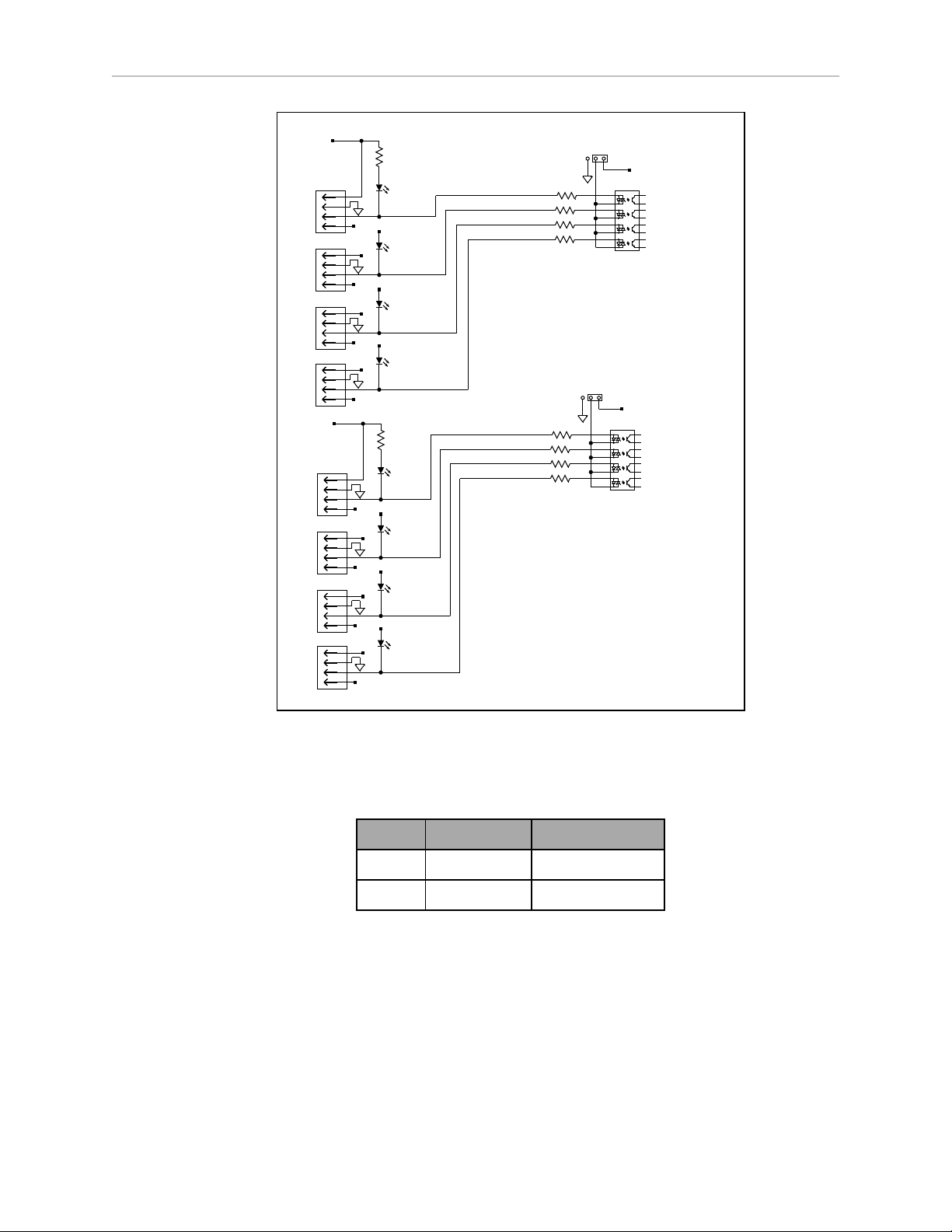
Chapter 6: Connectivity
161
152
143
134
125
116
8 9
7 10
161
152
143
134
125
116
8 9
7 10
SHIELD_GND
SHIELD_GND
SHIELD_GND
3
4
2
1
3
4
2
1
SHIELD_GND
1
2
4
3
VBAT
9.09K
3
4
2
1
VBAT
VBAT
VBAT
SHIELD_GND
SHIELD_GND
SHIELD_GND
3
4
2
1
3
4
2
1
1
1
PS2805_4
1
1
1
1
1
1
1
1
INPUTS 9-16 Have options for PIC outputs
IO_INPUT1
3
4
2
1
J45
1
2
4
3
J40
9.09K
DS27
DS26
SHIELD_GND
IN_1
I
N_2
J47
DS29
IO_INPUT2
IO_INPUT3
VBAT
VBAT
VBAT
VBAT
I
N_3
I
N_4
J46
DS28
IO_INPUT4
IN_5
IN_6
IN_7
IN_8
J48
J49
J50
J51
PS2805_4
123
VBAT
VBAT
IO_INPUT5
IO_INPUT6
IO_INPUT7
IO_INPUT8
3.9K
3.9K
3.9K
3.9K
123
3.9K
3.9K
3.9K
3.9K
DS30
DS31
DS32
DS33
INPUTS 1-8 Targeted for ACTIVE LOW IN,
9-16 for ACTIVE HIGH IN.
JP7
JP6
Move to 2/3 position ACTIVE HIGH IN
Jumpers shown as ACTIVE LOW IN
User Beeper, J56. Micro MATE-N-LOK, mates with TE 2C 794617-2.
This signal goes low when the platform is moving. It can be used to drive a beeper.
6.3 Standard Platform Connections
NOTE:All of these are in the payload bay.
If there is no conflicting connection in the Connectivity on page 83, these connections are available for use with standard- and user-supplied accessories. The antennas and joystick come
with the platform.
Figure 6-3. Input Schematic
Pin No. Designation Notes
1 BATTERY 22-29 VDC, 0.1 A
2 SOUNDER ACTIVE LOW
LD Cart Transporter User's Guide, 14766-000 Rev B
Page 89 of 190
Page 90
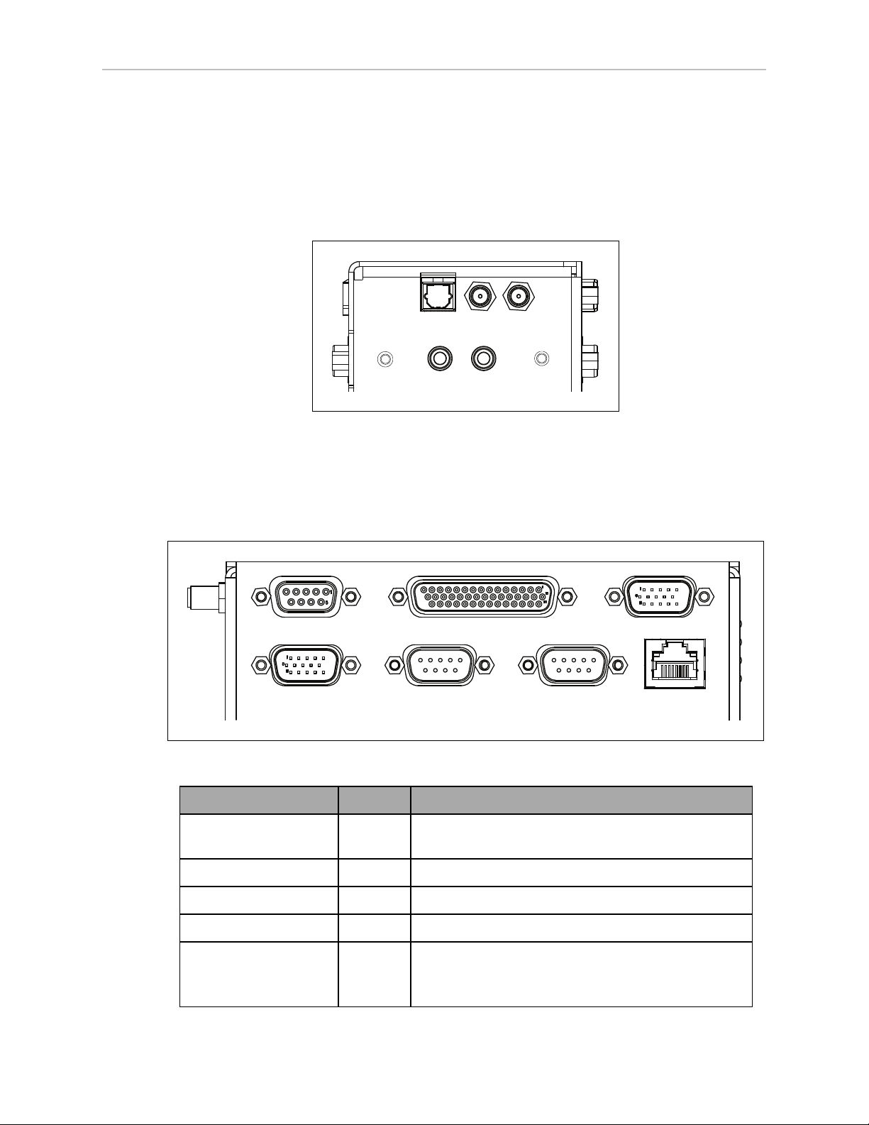
Chapter 6: Connectivity
Digital
Ant1
Ant2
Audio In
Audio Out
Audio Out
CAN Bus B Digital I/O
Analog I/O
User LANRS232-1RS232-2Aux Sensors
NOTE:If a connection is in Connectivity on page 83, it means that the description
here does not apply to the transporter, because that connection is being used for a
cart-specific use.
NOTE:Standard connectors, such as audio, are not covered here. These are on the
right side of the core, shown in the following figure:
Figure 6-4. Right Side of the Core
The left end of the robot core has 12 indicator lights. Their meanings are covered in Robot Core
Indicators on page 126.
Robot Core Front, Upper
Figure 6-5. Front Upper Core
Connection Type Description
User LAN RJ45,
Shielded
Aux Sensors HDB15M Side lasers
RS-232 x 2 DB9M Port 1 and Port 2, general use
CAN Bus B DB9F Consult Support for use.
General Ethernet, Auto-MDIX.
Digital I/O (HDB44F) HDB44F 16 digital inputs, in 4 banks of 4. Each bank can be
LD Cart Transporter User's Guide, 14766-000 Rev B
wired as active high or active low depending on the
connection of the BANK# terminal.
Page 90 of 190
Page 91
Chapter 6: Connectivity
Connection Type Description
Analog I/O HDB15M General use
CAN Bus B
Connector type DB9F
Use CAN Bus
VINrange for each input is 0 to 30 V. The input is ON
when VIN> 4 V, OFF when VIN< 1.3 V.
16 digital outputs, protected low-side drivers. These
outputs should be wired to positive voltage through
the load. Output is open when OFF and grounded
when ON. Each open-drain output is capable of sinking 500 mA. May be used with loads connected to
VBAT, AUX_20V, _12V, or _5V. You must stay
within the allowed current capacity of the VBAT or
AUX power supplies.
Pin No. Designation Notes
1, 4, 8 No Connection
2 CANL_B CAN Communication differential pair
3, 6 GND Direct GND
5 SHIELDGND Bead filter to GND
7 CANH_B CAN Communication differential pair
9 CANB_12V_OUT_SW 12 V @ 0.5 A Max (switched in SW)
Digital I/O
Connector type HDB44F
Pin No. Hardware Software Notes
1 INPUT_1.1 Input_1.1 0 – 30 V Range, Rin= ~3.9 kΩ
2 INPUT_1.2 Input_1.2 0 – 30 V Range, Rin= ~3.9 kΩ
3 INPUT_1.3 Input_1.3 0 – 30 V Range, Rin= ~3.9 kΩ
Designation
4 INPUT_1.4 Input_1.4 0 – 30 V Range, Rin= ~3.9 kΩ
5 BANK1 Common for INPUT_1.X
6 INPUT_2.1 Input_2.1 0 – 30 V Range, Rin= ~3.9 kΩ
7 INPUT_2.2 Input_2.2 0 – 30 V Range, Rin= ~3.9 kΩ
LD Cart Transporter User's Guide, 14766-000 Rev B
Page 91 of 190
Page 92

Chapter 6: Connectivity
Designation
Pin No. Hardware Software Notes
8 INPUT_2.3 Input_2.3 0 – 30 V Range, Rin= ~3.9 kΩ
9 INPUT_2.4 Input_2.4 0 – 30 V Range, Rin= ~3.9 kΩ
10 BANK2 Common for INPUT_2.X
11 INPUT_3.1 Input_3.1 0 – 30 V Range, Rin= ~3.9 kΩ
12 INPUT_3.2 Input_3.2 0 – 30 V Range, Rin= ~3.9 kΩ
13 INPUT_3.3 Input_3.3 0 – 30 V Range, Rin= ~3.9 kΩ
14 INPUT_3.4 Input_3.4 0 – 30 V Range, Rin= ~3.9 kΩ
15 BANK3 Common for INPUT_3.X
16 INPUT_4.1 Input_4.1 0 – 30 V Range, Rin= ~3.9 kΩ
17 INPUT_4.2 Input_4.2 0 – 30 V Range, Rin= ~3.9 kΩ
18 INPUT_4.3 Input_4.3 0 – 30 V Range, Rin= ~3.9 kΩ
19 INPUT_4.4 Input_4.4 0 – 30 V Range, Rin= ~3.9 kΩ
20 BANK4 Common for INPUT_4.X
21 OUTPUT_1 Output_1
22 OUTPUT_2 Output_2
23 OUTPUT_3 Output_3
24 OUTPUT_4 Output_4
25 OUTPUT_5 Output_5
26 OUTPUT_6 Output_6
27 OUTPUT_7 Output_7
28 OUTPUT_8 Output_8
29 OUTPUT_9 Output_9
30 OUTPUT_10 Output_10
31 OUTPUT_11 Output_11
32 OUTPUT_12 Output_12
33 OUTPUT_13 Output_13
34 OUTPUT_14 Output_14
35 OUTPUT_15 Output_15
36 OUTPUT_16 Output_16
37 VBAT_IO_OUT4 VBAT @ 0.5 A Max
(shared with light pole)
LD Cart Transporter User's Guide, 14766-000 Rev B
Page 92 of 190
Page 93
Chapter 6: Connectivity
Designation
Pin No. Hardware Software Notes
38 VBAT_IO_OUT3 VBAT @ 0.5 A Max
39 VBAT_IO_OUT2 VBAT @ 0.5 A Max
40 VBAT_IO_OUT1 VBAT @ 0.5 A Max
41, 42,
43, 44
Digital Input Specifications
GND
Operational voltage range 0 to 30 VDC
OFF state voltage range 0 to 1.3 VDC
ON state voltage range 4 to 30 VDC
Operational current range 0 to 7.5 mA
OFF state current range 0 to 0.5 mA
ON state current range 1.0 to 7.5 mA
Impedance (Vin/Iin) 3.9 kΩ minimum
Current at Vin= +24 VDC Iin≤ 6 mA
NOTE:The input current specifications are provided for reference. Voltage sources
are typically used to drive the inputs.
Parameter Value
LD Cart Transporter User's Guide, 14766-000 Rev B
Page 93 of 190
Page 94
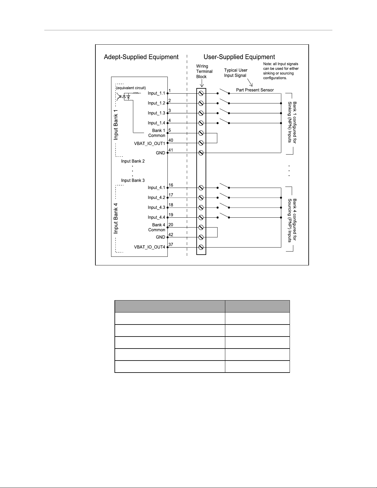
Chapter 6: Connectivity
Figure 6-6. Typical Digital Input Wiring Example
Table 6-1. Digital Output Specifications
Parameter Value
Power supply voltage range 5 - 30 VDC
Operational current range, per channel I
ON state resistance (I
= 0.5 A) Ron≤ 0.14 Ω @ 85° C
out
Output leakage current I
DC short circuit current limit 0.7 A ≤ I
≤ 500 mA
out
≤ 5 μA
out
LIM
≤ 1.7 A
LD Cart Transporter User's Guide, 14766-000 Rev B
Page 94 of 190
Page 95
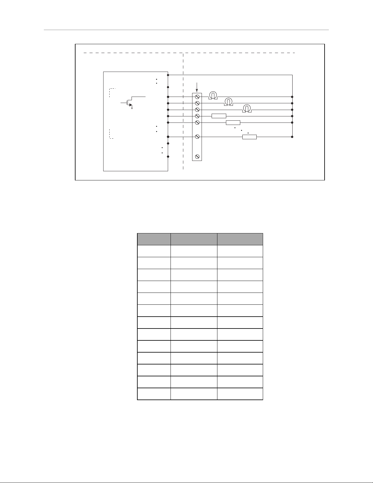
Chapter 6: Connectivity
Standard Equipment User-Supplied Equipment
Outputs 1-16
Typical User Loads
VBAT_IO_OUT1
VBAT_IO_OUT4
21
OUTPUT_1
22
OUTPUT_2
23
OUTPUT_3
24
OUTPUT_4
25
OUTPUT_5
36
OUTPUT_16
GND
Load
41
GND
44
Load
(equivalent
circuit)
Wiring Terminal Block
37
Load
40
Figure 6-7. Typical Digital Output Wiring Example
Analog I/O
Connector type HDB15M
Pin No. Designation Notes
1 ANALOG_IN1 0 – 10 V Range
2 ANALOG_IN2 0 – 10 V Range
3 ANALOG_IN3 0 – 10 V Range
4 ANALOG_IN4 0 – 10 V Range
5 ANALOG_IN5 0 – 30 V Range
6 ANALOG_IN6 0 – 30 V Range
7 ANALOG_IN7 0 – 30 V Range
8 ANALOG_IN8 0 – 30 V Range
9 ANALOG_OUT1 0 – 20 V Range
10 ANALOG_OUT2 0 – 20 V Range
l
The 0-10 V analog inputs have an input impedance of about 35 kΩ.
l
The 0-30 V analog inputs have an input impedance of about 110 kΩ.
l
The analog outputs have an output impedance of about 200 Ω.
11 ANALOG_OUT3 0 – 20 V Range
12 ANALOG_OUT4 0 – 20 V Range
13, 14, 15 GND
LD Cart Transporter User's Guide, 14766-000 Rev B
Page 95 of 190
Page 96
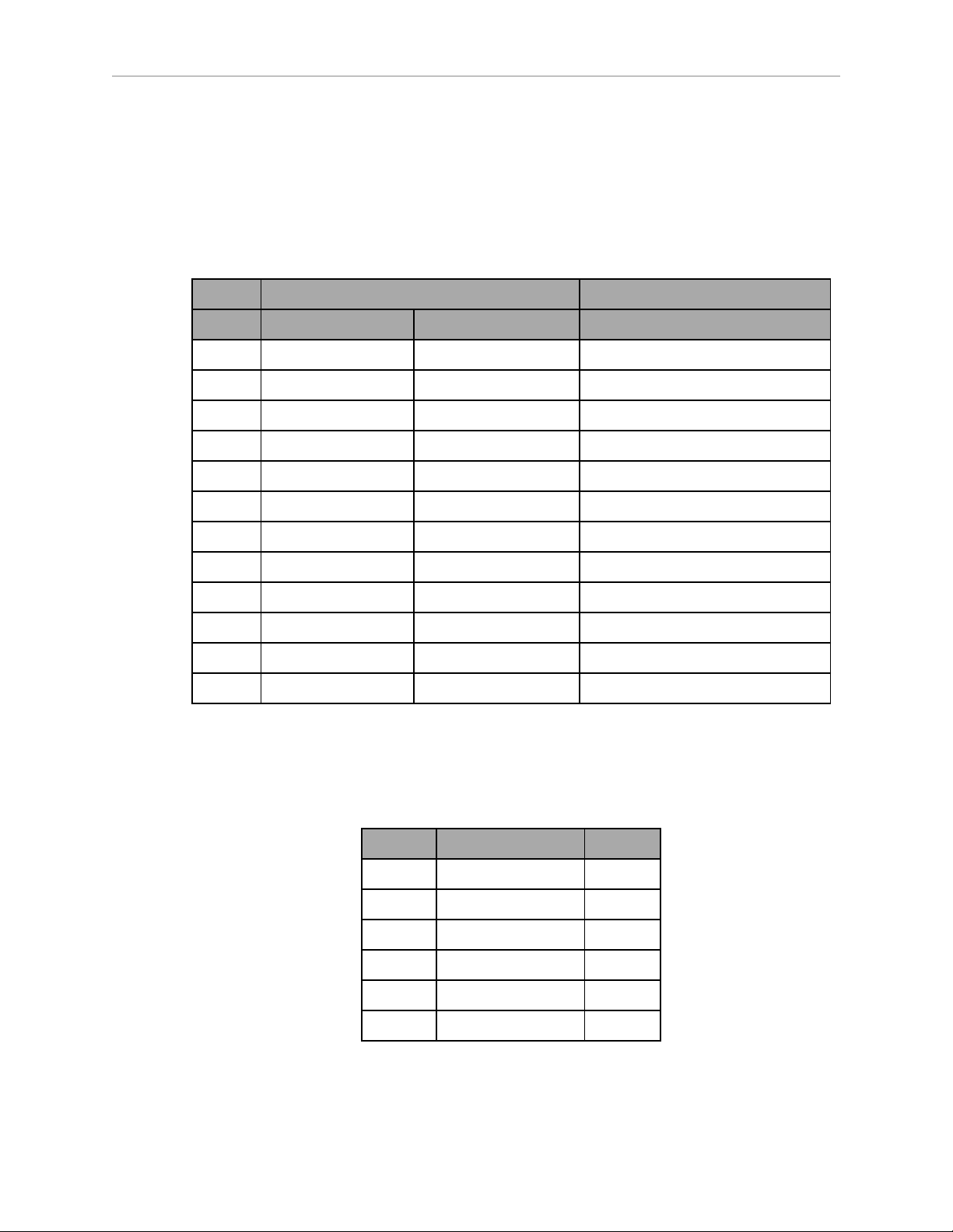
Chapter 6: Connectivity
The maximum output current of each analog output is 10 mA. Exceeding the maximum
output current will result in damage to the analog output module.
Aux Sensors
Connector type HDB15M
Use Side (vertical) and low sensing (foot)lasers
Designation
Pin No. Hardware Software Notes
1 RS232_VERT1_TXD /dev/ttyUSB5
2 RS232_VERT2_TXD /dev/ttyUSB6
3 RS232_FOOT_TXD /dev/ttyUSB7
4 5V_SW1 USB_1_and_2_Power 5 V @ 1 A (shared with USB port 1)
5, 10 SW_20V_VERT Vertical_Laser_Power 20 V @ 300 mA
6, 7, 8 GND
9 5V_SW2 USB_1_and_2_Power 5 V @ 1 A (shared with USB port 2)
11 RS232_VERT1_RXD /dev/ttyUSB5
12 RS232_VERT2_RXD /dev/ttyUSB6
13 RS232_FOOT_RXD /dev/ttyUSB7
14 5V_SW3 USB_3_Power 5 V @ 1 A (shared with USB port 3)
15 SW_20V_FOOT Foot_Laser_Power 20 V @ 150 mA
RS232 1 & 2
Connector type DB9M
Use Port 1 and 2, General Use
Pin No. Designation Notes
1, 4, 6, 9 No Connection
2 RS232_USR#_RXD #=1 or 2
3 RS232_USR#_TXD #=1 or 2
5 GND
7 RS232_USR#_RTS #=1 or 2
8 RS232_USR#_CTS #=1 or 2
LD Cart Transporter User's Guide, 14766-000 Rev B
Page 96 of 190
Page 97
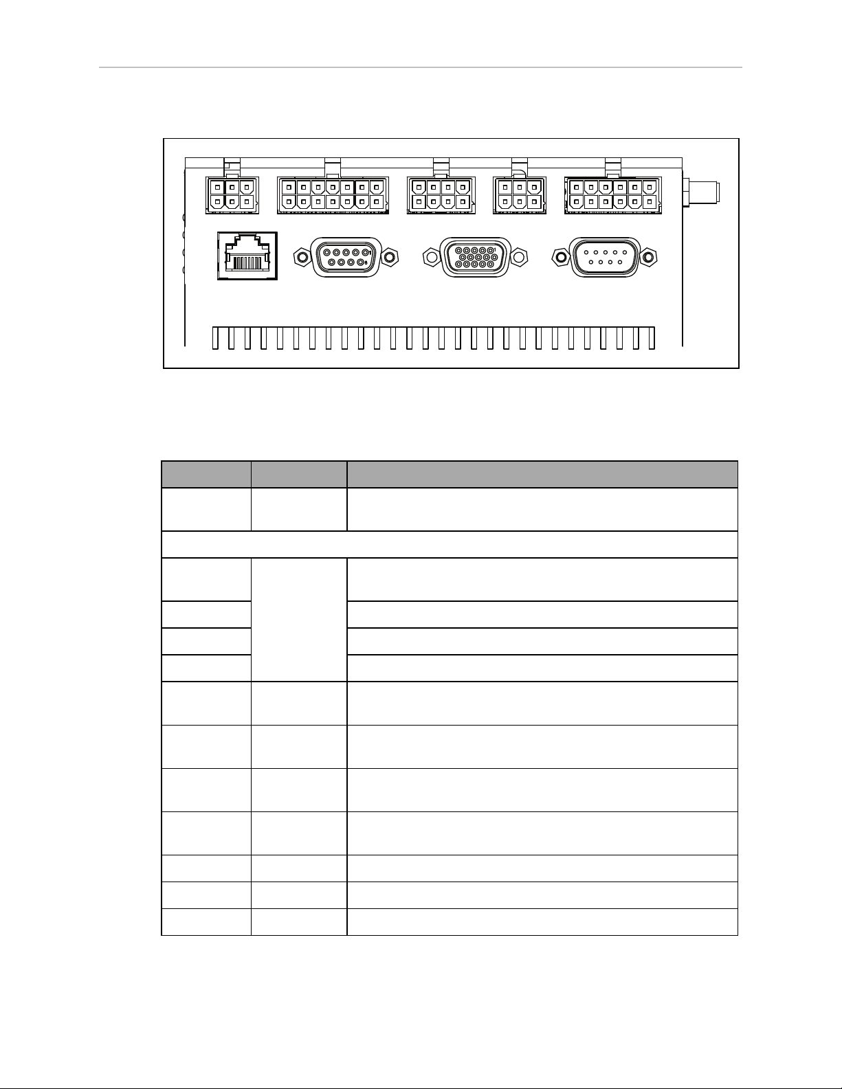
Robot Core Rear, Upper
Light Pole User Interface User Bumpers Aux Power User Power
Maint LAN Joystick HMI Panel Sonar 2
NOTE:The connectors in the top row of the Rear Upper Core mate with Molex
Mini-Fit Jr™ 5557 series receptacles.
Chapter 6: Connectivity
Figure 6-8. Rear Upper Core
Connection Type Description
Light Pole Mini-Fit 2 x 3 Connects to a user-supplied light tower with 3 lights and 1
buzzer, using a default configuration
NOTE:The following four functions are pins on the User Interface connector.
Brakerelease
ON Pins for user-supplied ON button
OFF Pins for user-supplied OFF button
ESTOP Pins for user-supplied E-Stop (must be used or jumpered)
User
Bumpers
Aux Power Mini-Fit
User Power Mini-Fit
Maint LAN RJ45,
Joystick DB9F Directly connected to the externally-mounted Joystick port
Mini-Fit 2 x 7 Pins for user-supplied brake release
Mini-Fit
2 x 4
2 x 3
2 x 6
Shielded
This connection is not used with a cart transporter.
5, 12, and 20 VDC Outputs
Battery and switched battery power
Directly connected to the externally-mounted Maintenance
Ethernet, Auto-MDIX.
HMI Panel HDB15F Operator screen, E-Stop, Brake_Rel, ON, OFF
Sonar 2 DB9M This connection is not used with a cart transporter.
LD Cart Transporter User's Guide, 14766-000 Rev B
Page 97 of 190
Page 98
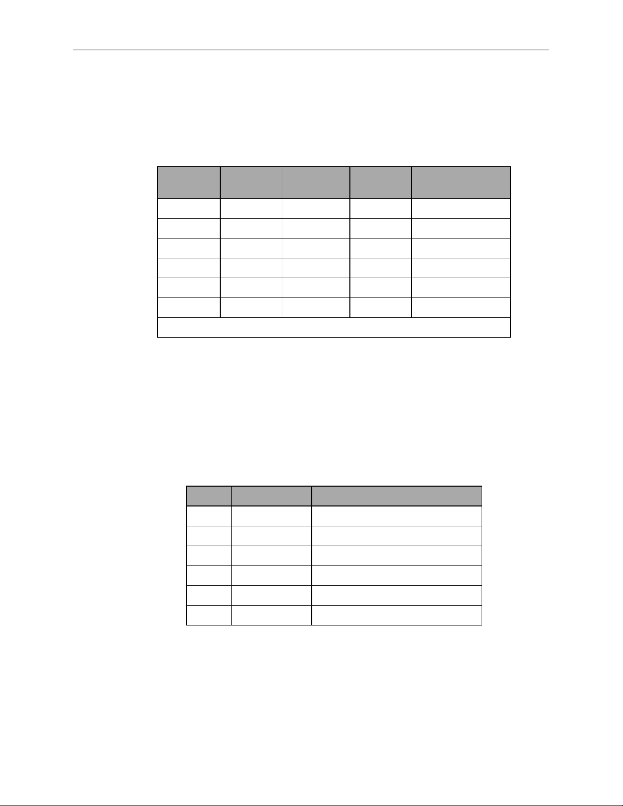
Chapter 6: Connectivity
Power Connections
The platform provides conditioned 5, 12, and 20 VDC, and raw (battery) 22 - 30 VDC power to
the platform’s and accessory electronics, including the onboard robot core and safety scanning
laser LIDAR (Light Detection And Ranging).
All power connectors are Mini-Fit®.
Nominal Qty Actual
5 VDC 1 5 VDC ±5% 1 A Switched Aux power
12 VDC 1 12 VDC ±5% 1 A Switched Aux power
20 VDC 1 20 VDC ±5% 1 A Switched Aux power
22 - 30 VDC 2 battery 4 A Switched
22 - 30 VDC 1* battery 10 A Switched
22 - 30 VDC 1* battery 10 A Safe, Switched
* 10 A Switched and 10 ASafe, Switched share the 10 A of current.
Maximum
Current
Description
Each supply has an associated LED, which, when lit, indicates that the port is actively
powered. See Robot Core Indicators on page 126.
The Safe 22 - 30 VDC supply automatically gets disconnected when the E-Stop button is
pressed or an obstacle is detected.
Light Pole
Connector type Mini-Fit®3 x 2
Use Light tower (user-supplied)
Pin No. Designation Notes
1 GND Cable shield
2 LIGHT_P1 Red
3 LIGHT_P2 Yellow or orange
4 VBAT_IO_OUT4 VBAT @ 0.5A Max (shared with DIO)
5 LIGHT_P3 Green
6 LIGHT_P4 Buzzer
LD Cart Transporter User's Guide, 14766-000 Rev B
Page 98 of 190
Page 99
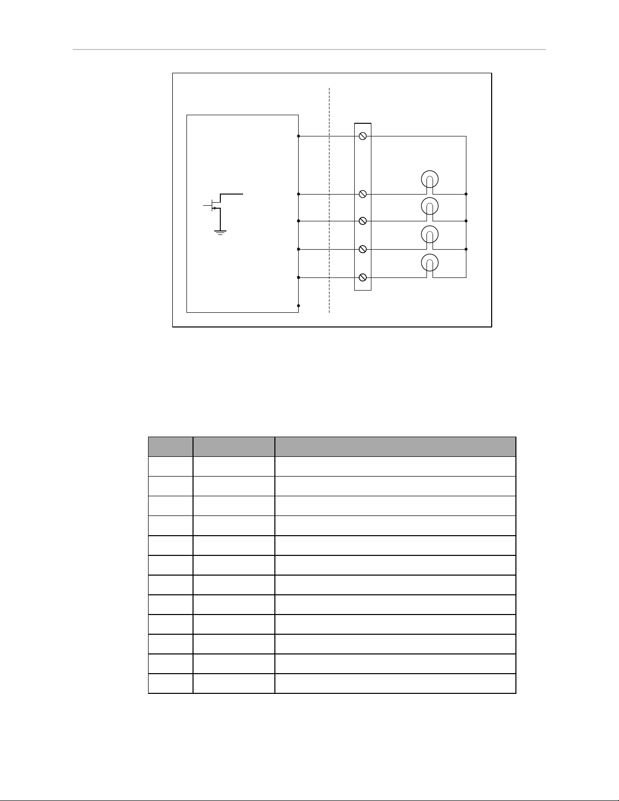
Chapter 6: Connectivity
VBAT_IO_OUT4
4
LIGHT_P1_N
2
LIGHT_P2_N
3
LIGHT_P3_N
5
LIGHT_P4_N
6
GND
1
(equivalent
circuit)
Typical user
load
Wiring
terminal
block
Factory-
Supplied Equipment
User-Supplied Equipment
Figure 6-9. Sample Light Pole Diagram
User Interface
Connector type Mini-Fit®7 x 2
Use Brake release, ON, OFF, E-Stop
Pin No. Designation Notes
1, 2, 3 FBAT_ALWAYS Fused VBAT @ 500 mA
4 ESTOP_USR_1L Short 4 & 11 to close ESTOP_USR_1
5 ESTOP_USR_2L Short 5 & 12 to close ESTOP_USR_2
6 ESTOP_OUT_1L Pins 6 & 13 short when ESTOP_CH1 is closed
7 ESTOP_OUT_2L Pins 7 & 14 short when ESTOP_CH2 is closed
8 OFF_BUTTON Short to FBAT_ALWAYS to signal OFF (min 1 s pulse)
9 START_BUTTON Short to FBAT_ALWAYS to signal ON (min 1 s pulse)
10 MOTOR_BRAKE Short to FBAT_ALWAYS for manual brake release
11 ESTOP_USR_1H Short 4 & 11 to close ESTOP_USR_1
12 ESTOP_USR_2H Short 5 & 12 to close ESTOP_USR_2
13 ESTOP_OUT_1H Pins 6 & 13 short when ESTOP_CH1 is closed
14 ESTOP_OUT_2H Pins 7 & 14 short when ESTOP_CH2 is closed
LD Cart Transporter User's Guide, 14766-000 Rev B
Page 99 of 190
Page 100
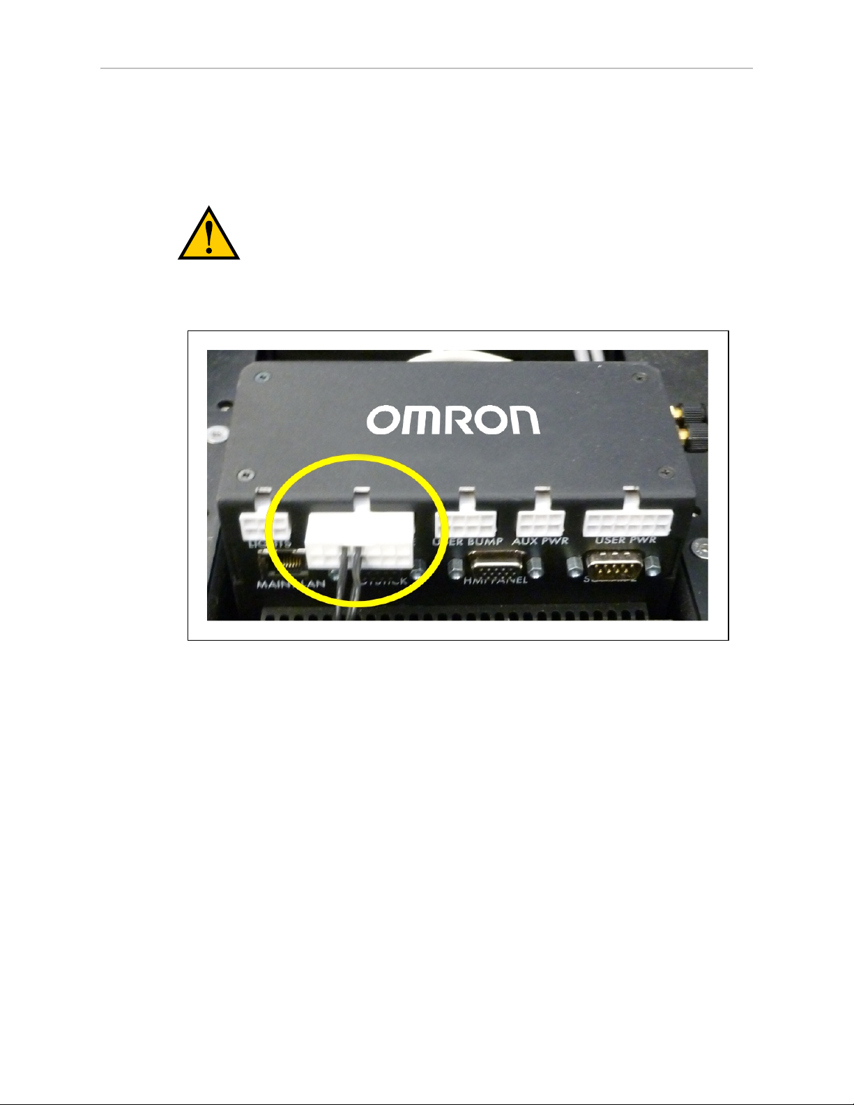
Chapter 6: Connectivity
NOTE:An E-Stop jumper or a user-supplied E-Stop button needs to be attached to
the E-STOP port on the User Interfaceconnector for the platform to function. The
jumper is provided as part number 12730-000L. An E-Stop button would be usersupplied.
CAUTION: If you are using a user-supplied E-Stop, you must run the Safety
Commissioning to verify the E-Stop’s functionality before putting the robot into
service.
NOTE:See the following figure.
Figure 6-10. E-Stop Jumper on Platform Core
LD Cart Transporter User's Guide, 14766-000 Rev B
Page 100 of 190
 Loading...