

Page 1
LCM100
Line Carrier Modem
OMMUNICATIONS
USER GUIDE
C
ATA
D
NDUSTRIAL
I
It is essential that all instructions contained in the User Guide are followed precisely to ensure proper operation of equipment.
Page 2

Product User Guide
FCC Information
Appropriate FCC info
DATA-LINC GROUP
PN 161-xxxxx-001A
Page 3
DATA-LINC GROUPp
LCM100 User’s Guide
LCM100
Line Carrier Modem
Introduction
In the line carrier system, the hot line supplies current to connected loads and is also used as a
carrier for data communication between modules. The Data-Linc LCM100 can communicate over
the same line in a 240 volt single phase system or on any individual phase of a three-phase
system.
Note: It will be necessary to have a signal coupler installed to ensure communications over
different lines of the 240 volt, single phases system.
In the three-phase power environment, communication will occur freely if both devices are
connected on the same phase, but cross-phase communication will require line conditioning by
installation of a signal coupler between phases. As shown in Figure 1 below, two signal couplers
are sufficient for all cross-plane combinations in a three-phase system. Installation of a signal
coupler at the power distribution panel is fully described under the line conditioning section of
this manual.
Hot
120V signal coupler Load
meter &
circuit neutral 220V
breaker
Hot
Figure 1: Connecting a Signal Coupler, Single Phase System
The green wire is reference (earth) ground. It serves also as chassis ground and reduces
equipment susceptibility to RF current, static discharge and interference from fluorescent lamps.
The LCM100 system is designed to operate with a reference ground located at the power
distribution panel. Reference ground is usually connected to the copy ground bus or to the
distribution panel frame.
When the power cord is connected to a three-wire AC power outlet, the bottom round connector
serves to ground the chassis, protecting against shock hazard, susceptibility to electro-magnetic
interference and possible spurious emissions.
120V Load
PN 161-09998-001A
2
Page 4

DATA-LINC GROUPp
LCM100 User’s Guide
Note: If a three-to-two-wire adapter is used to connect to a two-wire AC outlet, the ground lead
of the adapter must be connected to earth ground to complete the ground system. An open
ground connection may cause a communications defect and/or shock hazard.
Line conditioners in the form of isolators, regulators and surge protectors may be present in the
computer system in order to provide clean power, especially on non-dedicated lines. The
LCM100 has integral surge protection.
Note: The LCM100 should not be plugged into isolator or surge protector devices as this may
cause signal degradation. If Detect indicators do not illuminate with both units connected to line
power, a coupling capacitor may be required for cross-phase communication (see appendix B).
Initial Operation
The LCM100 is completely transparent. This means that once the system is correctly installed, it
will not be apparent to the system. Like a cable, it requires no attention other than a reliable
connection.
With the modules connected to their respective equipment as previously described, ensure that
both module’s, Detect and Power indicators are illuminated. Data transfer will occur in both
directions as commanded by the interconnected equipment.
Sometimes a random glitch on power lines will cause erroneous data characters to appear at
either end of the communications line. This is to be expected, especially during periods when the
equipment is idle. Error correction procedures appropriate to your computer operating system
can be taken to remove the spuratic characters.
Troubleshooting
The following are methods of eliminating the cause of communication difficulties, which may
occur with the LCM100.
Fuses
Each module has a fuse located internally. Replace only with a fuse of similar rating of ½ amp 3
AG.
Troubleshooting Technique
If communication difficulties are encountered, first check for proper cable connections at the
power receptacles, and at both RS-232C interface cables. An indication of faulty FSK
communication between modules is a missing Detect indicator at either module. An indication of
faulty power line connection is the missing power indicator at either module.
To isolate a communications problem from the RS-232C interface, simply connect the equipment
directly, without going through the LCM100 modules. If the problem persists, then the defect
probably lies within the equipment and not the LCM100.
To isolate line carrier problems from the power distribution circuits, connect each module’s
power receptacle into a common power distribution circuit—for example, at the same outlet or
through an extension cord. If communications occur at one outlet, but not at another, then the
problem is probably due to lack of coupling between phases.
Note: The LCM100 does not use the handshake lines; therefore, communication protocol codes
will possibly need to be implemented in order for the LCM100 to operate effectively.
PN 161-09998-001A
3
Page 5

DATA-LINC GROUPp
LCM100 User’s Guide
Communication Failure
Carrier Detect
Off
RS-232C Input Modulator/Oscillator
Failure Failure
Power
Indicator Off Receiver Signal Modulator Cable/CNX
Circuitry Coupler Oscillator Failure
Failure Failure Failure
Circuit Breaker
Open
Fuse Power Breaker
Blows Fails Open
Fault Tree Legend
results from compensation of fault
events through the input of an OR gate
Basic fault event
OR gate denotes that an output event
occurs if any one or more of the input
events occur.
Figure 2: Fault Tree
Rectangle denotes an event which
PN 161-09998-001A
4
Page 6

DATA-LINC GROUPp
LCM100 User’s Guide
LCM100 Technical Specifications
Power requirements 120 volts at +/- 10%, 50-60 Hz, 4.5 watts. Power is on when
module(s) are connected
Data Rate Up to 9600 baud
Data Formats Any serial asynchronous format up to 9600 baud
Operation Full Duplex
Receive Sensitivity 20 millivolts
Transmit Level 250mW into 3 ohms
Interface EIA RS-232C Interface Standard
Mating Connectors Female, DB-25P
FSK Carrier Highband: Space 150 kHz, Mark, 156.5 kHz
Lowband: Space 100 kHz, Mark, 106.5 kHz
Bandwidth: 10 kHz
Indicators Power: Red LED indicates power on
Carrier Detect: Green LED indicates carrier signal is being
received over power line from other module
Environment Operating Temperature: 32o to 158 o F (0 to 70 o C)
Storage: -40to 185 F (-40o to 85 C)
Humidity: Up to 90% (non-condensing)
Dimensions
Technical Support
Data-Linc Group maintains a fully trained staff of service personnel who are capable of providing
complete product assistance. They can provide you with technical, application and
troubleshooting, spare parts and warranty assistance. Our technical staff are based in Redmond,
Washington USA and may be reached at 425.882.2206 or email support@data-linc.com
Product Warranty
Data-Linc Group warrants equipment of its own manufacture to be free from defects in material
and workmanship for one year from date of shipment to original user. Data-Linc Group will
replace or repair, at our option, any part found to be defective. Buyer must return any part
claimed defective to Data-Linc Group, transportation prepaid.
Return Material Authorization
If a part needs to be sent to the factory for repair, contact Data-Linc Group’s corporate office and
request a Return Material Authorization (RMA) number. The RMA number identifies the part and
the owner and must be included with the part when shipped to the factory.
Contact Information
Corporate Office Data-Linc Group
3535 Factoria Blvd. SE
Suite 100
Bellevue, WA 98006
Telephone: 425.882.2206
Fax: 425.867.0865
Email: info@data-linc.com
Web site: www.data-linc.com
7.25” x 4.85” x 2.55” (184mm x 123mm x 64mm)
PN 161-09998-001A
5
Page 7

DATA-LINC GROUPp
LCM100 User’s Guide
Appendix A
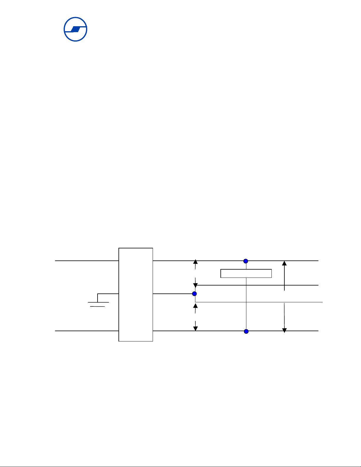
RS-232 Connector Pin Assignments
Both modules of the LCM100 have female DB-25 connectors which can be directly connected to
DTE and DCE equipment. All output levels are a minimum of +6 volts when active and a
maximum of –6 volts when inactive, measured in a 3k ohm load. Inputs will sink 10Ma and have
a typical turn-on threshold of +1.25 volts and a turn-off threshold of +0.8 volts.
J2
Pin Description
1
2
3
4
5
6
7
8
Ground
In the RS-232C environment, this line provides a safety frame ground for
RS-232 equipment.
Transmit Data (Output)
This line transfers data to the RS-232C device.
Receive Data (Input)
This line accepts data input from the RS-232C device.
Request to Send
Request to send output; indicates that the terminal is ready to transmit data.
This line is enabled, pulled up to +12 volts through a 4.7K ohm resistor.
Clear to Send
Clear to Send input; acknowledges that the terminal may begin transmission. This line is enabled, pulled up to +12 volts through a 4.7K ohm resistor. Data Set Ready Data Set Ready input; acknowledges that the remote device is on and operational. This line is enabled, pulled up to +12 volts through a 4.7K ohm resistor.
Signal Ground
This line provides a common signal connection.
2
Carrier
Detect (Output)
This line is a high level (+12 VDC) when carrier is detected, and a low level
(-12 VDC) when carrier is not detected.
PN 161-09998-001A
6
Page 8

DATA-LINC GROUPp
LCM100 User’s Guide
Connector J2 (Female)
Please note that male pin numbering is a mirror image of the female connector depicted below:
13 12 11 10 9 8 7 6 5 4 3 2 1
25 24 23 22 21 20 19 18 17 16 15 14
Figure 3: DB-25P J2 Connector Pins
J2
Pin Description
9-19 Pins 9-19 are unused, open. 20
Notes
1. On the LCM100-1 module pin 8 is not carried at the connector through P3 because most
computers provide this signal. Pin 8 may be carried to the connector, if desired.
2. On the LM100-2 module, the carrier detect signal is available at the connector because the
interconnected equipment is receiving a signal. Pin 8 may be disconnected at P3, if desired.
Data Terminal Ready
Data Terminal Ready output; indicates that the terminal is on and
operational. This line is enabled, pulled up to +12 volts through a 4.7K ohm
resistor.
PN 161-09998-001A
7
Page 9

DATA-LINC GROUPp
LCM100 User’s Guide
Appendix B
Line Conditioning
In some industrial installations, power lines must be conditioned to prevent the FSK signal from
being shunted by distributed capacitance possibly associated with other loads connected to the
line. Motors and transformers, for example, may have very high distributed capacitance.
Adequate communication in such circumstances may require: 1) installation of signal couplers at
the power distribution panel to provide a low impedance path between different hot lines; 2)
isolation of noisy equipment or equipment that presents a low impedance to high frequency
signals, such as some power line filters commonly used with computer equipment.
Signal Couplers
One signal coupler is sufficient for all cross-phase communications in a signal phase system.
See Figure 4 below:
DTE DCE
FSK
A Phase
Signal LCM100-1 RS-232C
Coupler
B Phase
Signal
Coupler
C Phase FSK
LCM100-2 RS-232C
Neutral
Figure 4: Signal Coupler in Three Phase Systems
PN 161-09998-001A
8
Page 10

DATA-LINC GROUPp
Appendix C
System Block Diagram
Data Terminal
Equipment
RS-232C
Interface
LCM100-2
LCM100 User’s Guide
Data Communications
Equipment
RS-232C
LCM100-1
Interface
DB-25P
Connectors
w/Cable
Data
Out
Data
In
Pin 2
Pin 3
Pin 8
Pin 7
Signal Ground
Data
In
Data
Out
Carrier
Detect
Output
Frequency
Modulator
Lowband
Oscillator
Highband
Receiver/
Demodulator
Carrier
Detect
Circuit
AC Power
Lines
Demodulator
Lowband
Receiver/
Carrier
Detect
Circuit
Highband
Oscillator
Frequency
Modulator
Data
Out
DB-25P
Connectors
w/Cable
Pin 2
Pin 3
Pin 7
Signal Ground
Data
In
Data
Out
PN 161-09998-001A
9
 Loading...