

Page 1

Smart Sensors
Laser Type
Cat. No. Z197-E1-02A
ZX-L-N Series
USER’S MANUAL
Page 2

ÇÕǹÇ?Ç ëÊ 1 èÕ ëÊ 2 èÕ ëÊ 3 èÕ ëÊ 4 èÕ
Introduction
Section 1 Section 2 Section 3 Section 4 Section 5 Section 6 Section 7
Introduction
Section 1
Section 2
Section 3
Section 4
Section 5
Section 6
Section 7
APPLICATION CONSIDERATIONS (Please Read)
FEATURES
PREPARATION FOR MEASUREMENT
BASIC OPERATION
MAIN APPLICATIONS AND SETTING METHODS
DETAILED SETTINGS
AUXILIARY FUNCTIONS
APPENDIX
User’s Manual
Smart Sensors
ZX-L-N Series
Page 3

ii
Introduction
Introduction
ZX-L-N
User’s Manual
Introduction
Introduction
Thank you for purchasing the ZX-L-N Series Smart Sensor. This manual provides information
regarding functions, performance and operating methods that are required for using the
sensor.
When using the ZX-L-N Smart Sensor, make sure to observe the following:
• The ZX-L-N Smart Sensor must be operated by personnel knowledgeable in electrical
engineering.
• To ensure correct use, please read this manual thoroughly to deepen your
understanding of the product.
• Please keep this manual in a safe place so that it can be referred to whenever
necessary.
Page 4

iii
ZX-L-N
User’s Manual
Introduction
Introduction
Introduction
READ AND UNDERSTAND THIS DOCUMENT
Please read and understand this document before using the products. Please consult your OMRON representative if
you have any questions or comments.
WARRANTY
OMRON’s exclusive warranty is that the products are free from defects in materials and workmanship for a period of
one year (or other period if specified) from date of sale by OMRON.
OMRON MAKES NO WARRANTY OR REPRESENTATION, EXPRESS OR IMPLIED, REGARDING NONINFRINGEMENT, MERCHANTABILITY, OR FITNESS FOR PARTICULAR PURPOSE OF THE PRODUCTS. ANY
BUYER OR USER ACKNOWLEDGES THAT THE BUYER OR USER ALONE HAS DETERMINED THAT THE
PRODUCTS WILL SUITABLY MEET THE REQUIREMENTS OF THEIR INTENDED USE. OMRON DISCLAIMS ALL
OTHER WARRANTIES, EXPRESS OR IMPLIED.
LIMITATIONS OF LIABILITY
OMRON SHALL NOT BE RESPONSIBLE FOR SPECIAL, INDIRECT, OR CONSEQUENTIAL DAMAGES, LOSS OF
PROFITS OR COMMERCIAL LOSS IN ANY WAY CONNECTED WITH THE PRODUCTS, WHETHER SUCH CLAIM
IS BASED ON CONTRACT, WARRANTY, NEGLIGENCE, OR STRICT LIABILITY.
In no event shall responsibility of OMRON for any act exceed the individual price of the product on which liability is
asserted.
IN NO EVENT SHALL OMRON BE RESPONSIBLE FOR WARRANTY, REPAIR, OR OTHER CLAIMS REGARDING
THE PRODUCTS UNLESS OMRON’S ANALYSIS CONFIRMS THAT THE PRODUCTS WERE PROPERLY
HANDLED, STORED, INSTALLED, AND MAINTAINED AND NOT SUBJECT TO CONTAMINATION, ABUSE,
MISUSE, OR INAPPROPRIATE MODIFICATION OR REPAIR.
SUITABILITY FOR USE
THE PRODUCTS CONTAINED IN THIS DOCUMENT ARE NOT SAFETY RATED. THEY ARE NOT DESIGNED OR
RATED FOR ENSURING SAFETY OF PERSONS, AND SHOULD NOT BE RELIED UPON AS A SAFETY
COMPONENT OR PROTECTIVE DEVICE FOR SUCH PURPOSES. Please refer to separate catalogs for OMRON's
safety rated products.
OMRON shall not be responsible for conformity with any standards, codes, or regulations that apply to the
combination of products in the customer’s application or use of the product.
At the customer’s request, OMRON will provide applicable third party certification documents identifying ratings and
limitations of use that apply to the products. This information by itself is not sufficient for a complete determination of
the suitability of the products in combination with the end product, machine, system, or other application or use.
The following are some examples of applications for which particular attention must be given. This is not intended to
be an exhaustive list of all possible uses of the products, nor is it intended to imply that the uses listed may be suitable
for the products:
Outdoor use, uses involving potential chemical contamination or electrical interference, or conditions or uses not
described in this document.
Nuclear energy control systems, combustion systems, railroad systems, aviation systems, medical equipment,
amusement machines, vehicles, safety equipment, and installations subject to separate industry or government
regulations.
Systems, machines, and equipment that could present a risk to life or property.
Please know and observe all prohibitions of use applicable to the products.
NEVER USE THE PRODUCTS FOR AN APPLICATION INVOLVING SERIOUS RISK TO LIFE OR PROPERTY
WITHOUT ENSURING THAT THE SYSTEM AS A WHOLE HAS BEEN DESIGNED TO ADDRESS THE RISKS, AND
THAT THE OMRON PRODUCT IS PROPERLY RATED AND INSTALLED FOR THE INTENDED USE WITHIN THE
OVERALL EQUIPMENT OR SYSTEM.
PERFORMANCE DATA
Performance data given in this document is provided as a guide for the user in determining suitability and does not
constitute a warranty. It may represent the result of OMRON’s test conditions, and the users must correlate it to actual
application requirements. Actual performance is subject to the OMRON Warranty and Limitations of Liability.
CHANGE IN SPECIFICATIONS
Product specifications and accessories may be changed at any time based on improvements and other reasons.
It is our practice to change model numbers when published ratings or features are changed, or when significant
construction changes are made. However, some specifications of the product may be changed without any notice.
When in doubt, special model numbers may be assigned to fix or establish key specifications for your application on
Page 5

iv
Introduction
Introduction
ZX-L-N
User’s Manual
Introduction
your request. Please consult with your OMRON representative at any time to confirm actual specifications of
purchased products.
DIMENSIONS AND WEIGHTS
Dimensions and weights are nominal and are not to be used for manufacturing purposes, even when tolerances are
shown.
ERRORS AND OMISSIONS
The information in this document has been carefully checked and is believed to be accurate; however, no
responsibility is assumed for clerical, typographical, or proofreading errors, or omissions.
PROGRAMMABLE PRODUCTS
OMRON shall not be responsible for the user’s programming of a programmable product, or any consequence thereof.
COPYRIGHT AND COPY PERMISSION
This document shall not be copied for sales or promotions without permission.
This document is protected by copyright and is intended solely for use in conjunction with the product. Please notify us
before copying or reproducing this document in any manner, for any other purpose. If copying or transmitting this
document to another, please copy or transmit it in its entirety.
Page 6
v
ZX-L-N
User’s Manual
Introduction
Meanings of Signal Words
Introduction
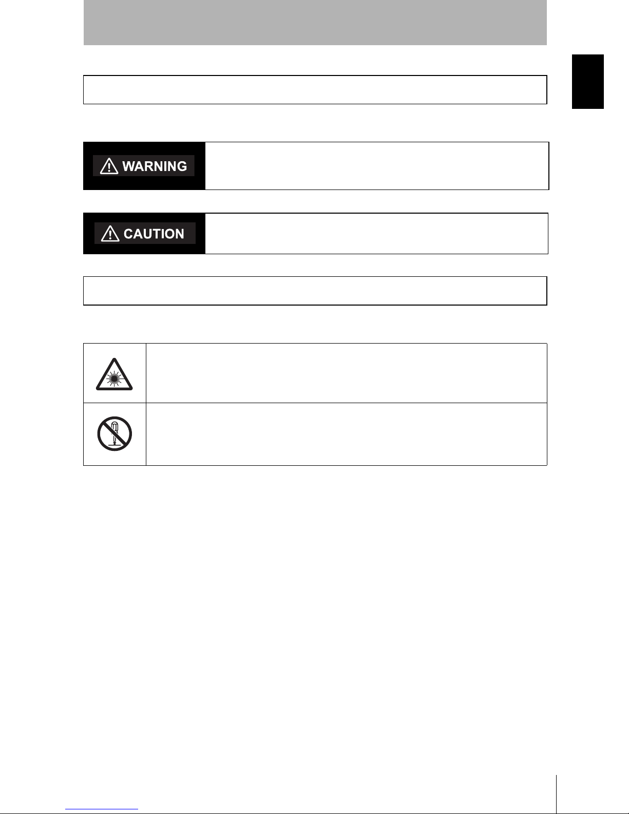
The following signal words are used in this manual.
The following alert symbols are used in this manual.
Meanings of Signal Words
Indicates a potentially hazardous situation which, if not avoided, will
result in minor or moderate injury, or may result in serious injury or
death. Additionally there may be significant property damage.
Indicates a potentially hazardous situation which, if not avoided,
may result in minor or moderate injury or in property damage.
Meanings of Alert Symbols
Indicates the possibility of laser radiation.
Indicates prohibition when there is a risk of minor injury from electrical shock
or other source if the product is disassembled.
Page 7
vi
Introduction
Laser Safety
ZX-L-N
User’s Manual
Introduction
ZX-LD/ZX-LD30V Reflective Sensor Type Sensor Head
ZX-LT Through-beam Type Sensor Head
Laser Safety
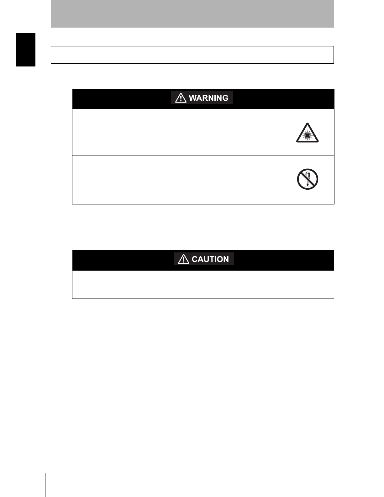
Never look into the laser beam.
Doing so continuously will result in visual impairment.
Do not disassemble the product.
Doing so may cause the laser beam to leak, resulting in the danger
of visual impairment.
Do not look into the laser beam.
Doing so continuously may result in visual impairment.
Page 8

vii
ZX-L-N
User’s Manual
Introduction
Laser Safety
Introduction
The ZX-LD, ZX-LDL, ZX-LDV, and ZX-LDVL Sensor Heads are Class
2 Laser Products according to EN 60825-1 (IEC 60825-1) and Class II Laser Products
according to FDA (21 CFR1040.10) (see note). The ZXLT Sensor Heads are Class
1 and Class II Laser Products, respectively. The ZX Series is meant to be built into final
system equipment. Pay special attention to the following precautions for the safe use of
the product:
Note: Europe: Class 1 and Class 2 of EN 60825-1: 1994 +A11:1996 +A2:2001
= IEC 60825-1:1993 +A1:1997 +A2:2001
U.S.A.: Class I and Class II of FDA (21 CFR1040.10)
As for the Laser Product Classifications, refer to the Appendix,
p.155
(1) ZX-LD/ZX-LD30V emits visual laser beam. Do not stare directly into the
laser.
Make sure that the laser beam path is terminated. If specular objects are present
in the laser beam path, make sure that they are prevented from reflecting the
laser beam.
When used without an enclosure, make sure the laser path from eye level is
avoided.
(2) To avoid exposure to hazardous laser radiation, do not displace nor remove the
protective housing during operation, maintenance, and any other servicing.
(3) As for countries other than those of Europe and the U.S.A., observe the
regulations and standards specified by each country.
(4) Label Indications
The EN and FDA labels are supplied with the product.
Replace the current labels with them according to the instructions given in the
manuals.
Page 9

viii
Introduction
Precautions for Safe Use
ZX-L-N
User’s Manual
Introduction
Please observe the following precautions for safe use of the products.
Installation Environment
• Do not use the product in environments where it can be exposed to inflammable/
explosive gas.
• Do not install the product close to high-voltage devices and power devices in order
to secure the safety of operation and maintenance.
Power Supply and Wiring
• The supply voltage must be within the rated range (DC12 to 24V±10%).
• Reverse connection of power supply is not allowed. Connection to AC power supply
is also not allowed.
• Open-collector outputs should not be short-circuited.
• High-voltage lines and power lines must be wired separately from this product.
Wiring them together or placing in the same duct may cause induction, resulting in
malfunction or damage.
• Always turn off the power supply before connecting or disconnecting cables and
connectors.
Others
• ZX-E series (linear proximity type), and ZX-W series (microwave type) and ZX-T
series (high-precision contact type) must not be connected. Combined use of ZX-L
with these series is not allowed.
• Do not attempt to dismantle, repair, or modify the product.
• Dispose of this product as industrial waste.
Precautions for Safe Use
Page 10

ix
ZX-L-N
User’s Manual
Introduction
Precautions for Correct Use
Introduction
Please observe the following precautions to prevent failure to operate, malfunctions, or
undesirable effects on product performance.
Installation of the Product
Installation Site
Do not install the product in locations subjected to the following conditions:
• Ambient temperature outside the rating
• Rapid temperature fluctuations (causing condensation)
• Relative humidity outside the range of 35 to 85%
• Presence of corrosive or flammable gases
• Presence of dust, salt, or iron particles
• Direct vibration or shock
• Reflective sensor of intense light (such as other laser beams or electric arc-welding
machines)
• Direct sunlight or near heaters
• Water, oil, or chemical fumes or spray
• Strong magnetic or electric field
Component Installation and Handling
Power Supply and Wiring
• To extend the output cables of Amplifier Units, shielded cables of the same
specifications as the output cables must be used.
• When using a commercially available switching regulator, make sure that the FG
terminal is grounded.
• If surge currents are present in the power lines, connect surge absorbers that suit
the operating environment.
• When using two ore more amplifier units, make sure that the linear GND line of the
amplifier units are connected to each other.
• Before turning ON the power after the product is connected, make sure that the
power supply voltage is correct, there are no incorrect connections (e.g. load shortcircuit) and the load current is appropriate. Incorrect wiring may result in breakdown
of the product.
• The cables must be 10m or shorter in total length, for both sensor head and amplifier
units. To extend the cable from the sensor head, an optional extension cable
(ZX-XCA) must be used. For extension of the cable of amplifier units, shielded
cables of the same type must be used.
• When using calculation units, make sure that the linear GND lines of the amplifier
units are connected to each other.
Precautions for Correct Use
Page 11

x
Introduction
Precautions for Correct Use
ZX-L-N
User’s Manual
Introduction
Warming Up
After turning ON the power supply, allow the product to stand for at least 10 minutes
before use. The circuits are still unstable just after the power supply is turned ON, so
measured values may fluctuate gradually.
Maintenance and Inspection
• Always turn OFF the power supply before adjusting or connecting/disconnecting the
sensor head.
• Do not use thinner, benzene, acetone or kerosene to clean the sensor head and
amplifier units. If large dust particles adhere to the front filter of the sensor head, use
a blower brush (used to clean camera lenses) to blow them off. Do not blow the dust
away with your mouth. To remove smaller dust particles, use a soft cloth (for lenses)
with a small amount of alcohol. Take care not to wipe them off with excessive force.
Scratches on the filter may cause errors.
Sensing Object For Reflective Type Sensor Head
The product cannot accurately measure the following types of objects: Transparent
objects, objects with an extremely low reflective sensor ratio, objects smaller than the
spot diameter, objects with a large curvature, excessively inclined objects, etc.
Mutual Interference
Inserting a calculation unit between amplifier units can prevent mutual interference
between two sensor heads. However, this may not work efficiently if one sensor head is
saturated and a laser beam of the other sensor head is input. If you are interested in
installing a calculation unit in order to prevent mutual interference, carry out a test using
the actual system beforehand.
Page 12

xi
ZX-L-N
User’s Manual
Introduction
Editor's Note
Introduction
Editor's Note
Page Format
TheresponsetimeoftheCH2AmplifierUnittowhichanexpressionissetwillbe
prolongedby1.0ms.Sincetheresponsetimeisinfluencedbythenumberofsamplesto
average,theactualresponsetimewillbe"responsetimebasedonthenumberof
samplestoaverage+1.0ms"
Section6
AUXILIARYFUNCTIONS
T FUNRUN
123
ZX-L
OperationManual
OperationManual
Section6
Section6
AUXILIARYFUNCTIONS
MeasuringwithMultiple
MeasuringwithMultiple
AmplifierUnits
AmplifierUnits
ThissectiondescribesthesettingswhenCalculatingUnitsareusedtoconnectmultiple
AmplifierUnits.
PerformingCalculations
PerformingCalculations
SettingtheNumberofSamplestoAveragep.66
AddingandSubtractingMeasurementResults
MovingtoFUNandCALC
1. SetthemodeswitchtoFUNontheCH2
AmplifierUnit.
UsetheLEFTandRIGHTKeystodisplay
[CALC]onthemaindisplay.
2.
3.
PresstheUPorDOWNKey.
UsetheUPorDOWNKeytoselectthe
desiredexpression.
PresstheENTKeytoconfirmthesetting.
Thesub-displaywillflash.
4.
5.
Thesettingwillberegistered.
Measurementresultscanbecalculatedbetween2AmplifierUnits.Theexpressionis
setontheCH2AmplifierUnitandthecalculationresultsarealsooutputfromtheCH2
AmplifierUnit.CalculationscanalsobeperformedbetweenSensorswithdifferent
measuringranges.
z Title of each section
z Header
z Overview
z Sub-header
z Index label
z Overview and points of
the function described
z Purpose of operation
z Display
z Keys or switches to be used
z Operation procedure and supplementary explanation
Indicates the contents of the page.
Describes the overview and
operation flow of the section.
Shows the chapter number
and contents.
Shows the contents of the
operation to be performed.
Shows the display status resulting
from the operation.
Illustrates the keys and switches to be used.
Explains the operation procedure and the display
status resulting from execution of the operation.
Helpful information regarding operation and
reference pages is introduced here using symbols.
* This page does not exist.
z Cross-header
Page 13
xii
Introduction
Editor's Note
ZX-L-N
User’s Manual
Introduction
Notational Conventions
Menu
In this manual, menu items displayed on the screen are enclosed with [ ].
Operation procedure
Operation steps are numbered to indicate their order.
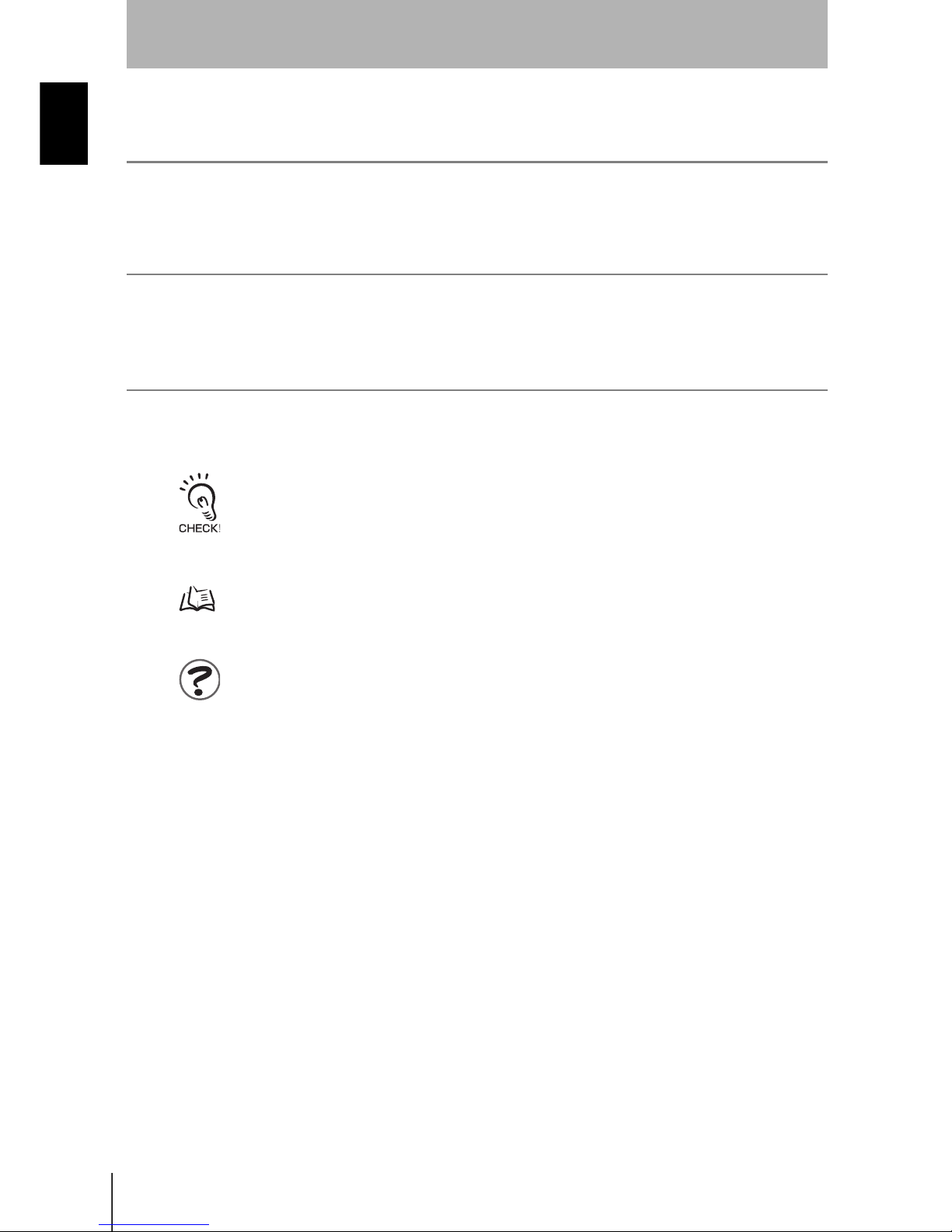
Visual Aids
Indicates points that are important to achieve the full product performance, such as operational
precautions and application procedures.
Indicates pages where related information can be found.
Indicates information helpful in operation.
Page 14

xiii
ZX-L-N
User’s Manual
Introduction
Contents
Introduction
Contents
Introduction ii
Precautions on Safety v
Laser Safety vi
Precautions for Safe Use viii
Precautions for Correct Use ix
Editor's Note xi
Contents xiii
Section 1 FEATURES 1
ZX-L Features 2
Section 2 PREPARATION FOR MEASUREMENT 9
Basic Configuration 10
Part Names and Functions 11
Installing the Amplifier Unit 16
Installing Sensor Heads 18
Connections 21
Wiring Input/Output Cables 27
Page 15

xiv
Introduction
Contents
ZX-L-N
User’s Manual
Introduction
Section 3 BASIC OPERATION 31
Flow of Operation 32
Basic Knowledge for Operation 34
Function Transition Charts 39
Setting the Auto Scale 42
Setting the Standard Received Light Amount 45
Measuring the Received Light Amount (Intensity Mode) 46
Section 4 MAIN APPLICATIONS AND SETTING METHODS 49
Measuring Height 50
Measuring Thickness 54
Measuring Eccentricity and Vibration 58
Measuring Edges 61
Section 5 DETAILED SETTINGS 65
Setting Number of Samples to Average 66
Changing Display Scales 67
Setting the Measurement Sensitivity (Gain Switching) 74
Using Hold Functions 76
Comparing Measured Values (Differentiation Function) 83
Comparing Measured Values (Previous Value Comparisons) 86
Entering Threshold Values 88
Linear Output 95
Setting Judgement Output Timing (Timer) 104
Page 16

xv
ZX-L-N
User’s Manual
Introduction
Contents
Introduction
Section 6 AUXILIARY FUNCTIONS 107
Measuring with Multiple Amplifier Units 108
Changing the Number of Display Digits 112
Reversing the Display 113
Adjusting Display Brightness (ECO Display) 115
Using the Zero Reset Function 116
Key Lock Function 122
Initializing Settings Data 123
Section 7 APPENDIX 125
Troubleshooting 126
Error Messages and Countermeasures 127
Q&A 129
Glossary 130
Specifications and Dimensions 132
Communication with the Smart Monitor is possible via the Interface Unit 144
Engineering Data 146
Quick Reference for Displays 152
Requirements from Regulations and Standards 155
Index 164
Revision History 168
Page 17

xvi
Introduction
Contents
ZX-L-N
User’s Manual
Introduction
MEMO
Page 18

Section 1 FEATURES
1
ZX-L-N
User’s Manual
Section 1
FEATURES
ZX-L Features 2
Page 19
2
Section 1 ZX-L Features
ZX-L-N
User’s Manual
Section 1
FEATURES
ZX-L Features
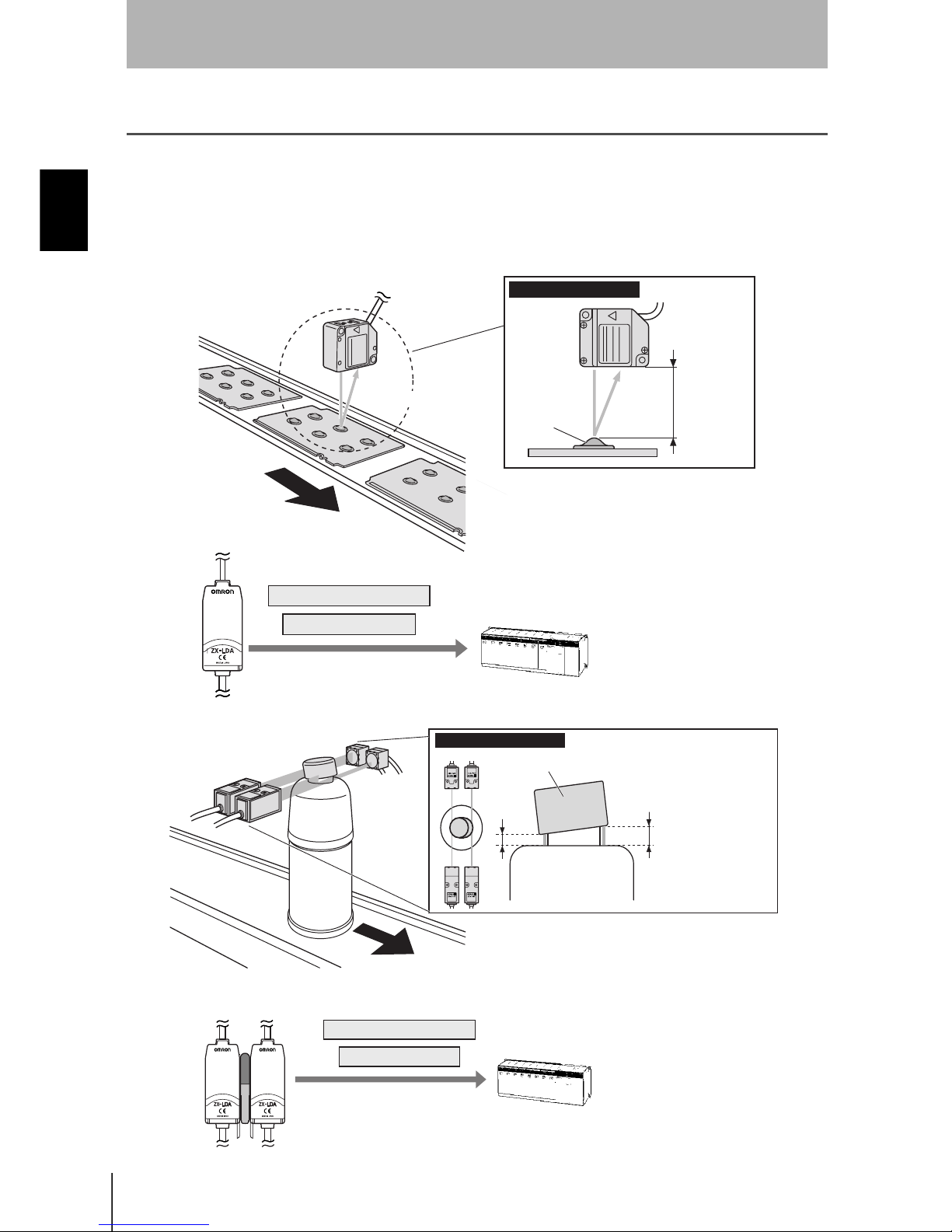
The ZX-L Series provide the reflective type for displacement measurement and through-beam
type for smart length measurement. Measurement is performed using laser. By irradiating
laser beams to the object, the sensor can measure the distance between the object and
sensor head, perform positioning and width judgement.
Example: Measuring the height of a PCB mold
Example: Detecting cap floating
Measured value outputs
Measuring method
Sensing
object
Distance
Judgement outputs
(Reflective Type)
Measured value outputs
Judgement outputs
Sensing object
Laser received or blocked
amounts are measured at
two points to detect whether
the cap is floating or inclined
by checking changes in the
measured values.
Measuring method
(Throughbeam Type)
Page 20
3
ZX-L-N
User’s Manual
Section 1 ZX-L Features
Section 1
FEATURES
The Compact Body Provides Sufficient Space.
The ZX-L series come in units as small as photoelectric sensors. This enables effective
use of limited installation space.
Many, Simple Functions
Measurement Ready at Power ON
The sensor can be used simply by installing and wiring it. Simply turn ON the power
and it is ready to operate.
The measurement results are displayed on the Amplifier Unit.
Simple Calculation Settings
Use a Calculating Unit to simply measure thickness and sum and difference
calculations between two measurements.
p.108
LDON
Calculating Unit
Thickness
Page 21

4
Section 1 ZX-L Features
ZX-L-N
User’s Manual
Section 1
FEATURES
Mutual Interference Prevention for Closely Mounted
Sensor Heads
The sensor has a mutual interference prevention function which allows multiple Sensor
Heads to be mounted close to each other.
This function is supported for up to two Sensor Heads by using ZX-CAL2 Calculating
Units.
p.24
Calculating
Unit
Page 22

5
ZX-L-N
User’s Manual
Section 1 ZX-L Features
Section 1
FEATURES
Compatibility between Sensor Heads and Amplifier
Units
Amplifier Units do not need to be changed when Sensor Heads are changed for
maintenance or to switch to new products.
Extendable Sensor Head Cables
Special extension cables are provided to extend sensor heads.
p.10
Special extension cable
Page 23

6
Section 1 ZX-L Features
ZX-L-N
User’s Manual
Section 1
FEATURES
Monitoring Measurement Status
Resolution Display for Sensing Object
The resolution can be displayed, allowing judgements to be made about detection
margins while viewing the resolution value.
p.39
Confirm Measurement Status on a Personal Computer
Use an Interface Unit and Smart Monitor to view measurement waveforms and log
measurement data on a personal computer. This function is useful for making on-site
measurement adjustments and for day-to-day quality control.
p.15, p.144
LDON
Resolution
Resolution
Deviation to be
detected
Smart Monitor
Interface Unit Amplifier Unit
Page 24

7
ZX-L-N
User’s Manual
Section 1 ZX-L Features
Section 1
FEATURES
Useful Warning Functions
Built-in Laser Life Monitor
When the laser of Sensor Head deteriorates, [LDDWN] will appear for approx. five
seconds on the Main Display when the power is turned ON. This assists in
understanding when the Sensor Head should be replaced with a new one.
SUB
(mm)
LDON ENABLEZERO
Page 25

8
Section 1
ZX-L-N
User’s Manual
Section 1
FEATURES
MEMO
Page 26

Section 2 PREPARATION FOR MEASUREMENT
9
ZX-L-N
User’s Manual
Section 2
PREPARATION FOR MEASUREMENT
Basic Configuration 10
Part Names and Functions 11
Installing the Amplifier Unit 16
Installing Sensor Heads 18
Connections 21
Wiring Input/Output Cables 27
Page 27

10
Section 2 Basic Configuration
ZX-L-N
User’s Manual
Section 2
PREPARATION FOR MEASUREMENT
Basic Configuration
The basic configuration of the ZX-L series Smart Sensors is shown below.
ZX-L series Smart Sensors are not compatible with other ZX series Smart Sensors. ZX-L cannot be used
with ZX-E, ZX-W and ZX-T series Smart Sensors.
p.26
p.16
p.18
p.24
Smart Monitor
(Software)
ZX-SW11
Enables operation of
Amplifier Units from
the personal computer
and monitoring
measured values.
Personal
Computer
Interface Unit
Used to connect to a
personal computer
or programmable
controller.
Sensor Head
ZX-LD
ZX-LT
Detects the
sensing object.
Basic Configuration
Amplifier Unit
ZX-LDA11-N (NPN type)
ZX-LDA41-N (PNP type)
Performs measurements and
outputs measurement results.
Power Supply
DC12 to 24V (±10%)
Extension
Cable
ZX-XC1A(1m)
ZX-XC4A(4m)
ZX-XC8A(8m)
ZX-XC9(9m)
To be used between
a Sensor Unit and
Amplifier Unit.
Only one extension
cable can be used.
ZX-XC9 can be used
for ZX-LD only.
Calculating
Unit
ZX-CAL2
Used to connect two
or more Amplifier
Units.
•
Calculation
•
Mutual interference
prevention
(Ver 3.0 or later)
ZX-SF11
(Ver 2.0 or later)
Connecting Cable
p.142
Commercially
available cross cable
Page 28
11
ZX-L-N
User’s Manual
Section 2 Part Names and Functions
Section 2
PREPARATION FOR MEASUREMENT
Part Names and Functions
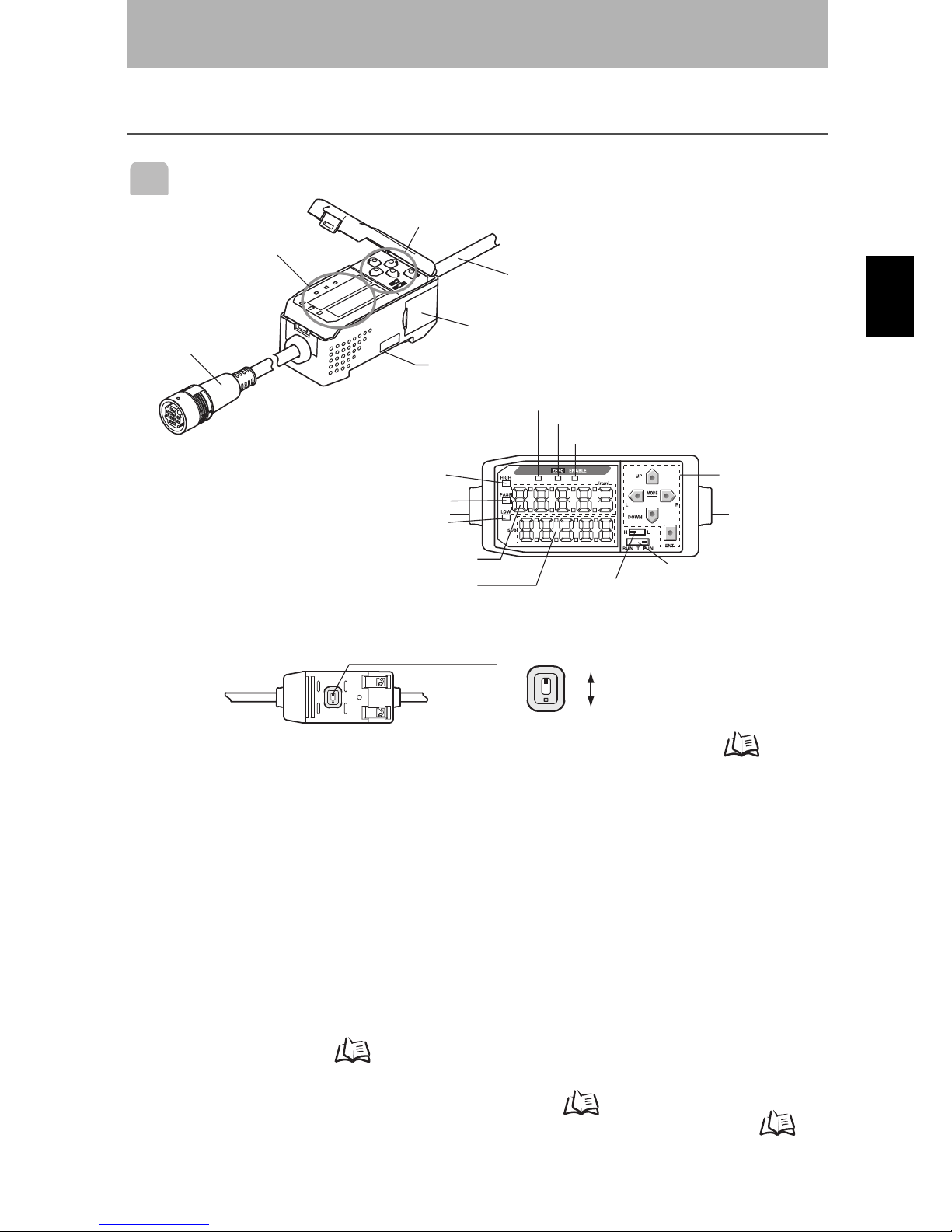
Amplifier Unit
(1) The input cable connects the Sensor Head.
(2) The current/voltage switch selects either a current or voltage linear output.
Monitor focus settings are also required when switching the output.
p.95
(3) The connectors connect Calculation and Interface Units.
(4) The output cable connects the sensor to the power supply and external devices,
such as sync sensors or programmable controllers.
(5) The Laser indicator lights while the Sensor Head is emitting a laser beam.
(6) The Zero Reset indicator lights when the zero reset function is enabled.
(7) The ENABLE indicator lights when the Sensor is ready for measurement. It goes
off when measurement is not possible (e.g. when the received light amount is
excessive or insufficient, when the measuring range is exceeded, or when the
Sensor Head is not connected when the power is turned ON).
(8) The HIGH indicator lights when the judgement result is HIGH.
(9) The PASS indicator lights when the judgement result is PASS.
(10) The LOW indicator lights when the judgement result is LOW.
(11) The main display shows measured values and function names.
(12) The sub-display shows additional information and function settings for
measurements.
Reading Displays p.35
(13) The threshold switch selects whether to set (and display) the HIGH or LOW threshold.
(14) The mode switch selects the operating mode. Switching Modes p.34
(15) The Control Keys set measurement conditions and make other settings. Key
Operations
p.36
LDON
(*)Operating and Display Sections
Operating Section(*)
Display Section(*)
(1) Input Cable
(4) Output Cable
(3) Connector (two connectors, one on each side)
(2) Current/voltage switch (on rear side)
(5) Laser indicator
(6) Zero Reset indicator
(7) ENABLE indicator
(15) Control Keys
(14) Mode switch
(13) Threshold switch
(12) Sub-display
(11)Main Display
(10) LOW indicator
(9) PASS indicator
(8) HIGH indicator
Current/voltage switch
Voltage output
Current output
Page 29

12
Section 2 Part Names and Functions
ZX-L-N
User’s Manual
Section 2
PREPARATION FOR MEASUREMENT
Sensor Head
Reflective type sensor head
Laser Emitter/Receiver
Section
Connector
To be connected to the Amplifier Unit.
NEAR Indicator
Both NEAR and FAR indicators are lit:
Measuring center distance
(Measuring range x 10%)
NEAR indicator is lit: Near side within measuring range
FAR indicator is lit: Far side within measuring range
Both NEAR and FAR indicators are blinking:
Outside measuring range
FAR Indicator
Page 30

13
ZX-L-N
User’s Manual
Section 2 Part Names and Functions
Section 2
PREPARATION FOR MEASUREMENT
Through-beam Type Sensor Head
Receiver (cable length: 0.5m)
Receiving section
Emitter (cable length: 0.5m)
Emitting
section
Connector
Sensor Head – Amplifier Unit
To be connected to the connecting cable.
Connector
To be connected to the receiver.
Cable: Black
Side View Attachment
Used to change the mount direction.
Fixing screw
Laser indicator
Lit while the laser is emitted.
Cable: Gray
Connector
Sensor Head – Amplifier Unit
To be connected to the connecting cable.
Connector
To be connected to the emitter.
Emitting
section
Emitter
Fixing screw
Receiving section
Receiver
Sensor Head – Amplifier Unit
Connecting Cable (cable length: 1.5m)
Page 31

14
Section 2 Part Names and Functions
ZX-L-N
User’s Manual
Section 2
PREPARATION FOR MEASUREMENT
Calculating Units
* Display Detail
Display (*) Connector (two connectors, one on each side)
Connection indicator
Lit when the Amplifier Unit is connected.
To be connected to the Amplifier Unit.
Page 32

15
ZX-L-N
User’s Manual
Section 2 Part Names and Functions
Section 2
PREPARATION FOR MEASUREMENT
Interface Units
(1) The communications connector connects the communications cable to the
computer.
(2) The Amplifier Unit connector connects to the Amplifier Unit.
(3) The power supply indicator lights while the power is supplied.
(4) BUSY: Lights during communications with the Smart Sensor.
ERR: Lights if an error occurs during communications with the Smart Sensor.
(5) BUSY: Lights during communications with the personal computer.
ERR: Lights if an error occurs during communications with the personal
computer.
* Display Detail
(2) Amplifier unit connector
(1) Communications
connector
Display (*)
(3) Power supply indicator
(4) Sensor communication indicator (BUSY/ERR)
(5) External terminal communication indicator (BUSY/ERR)
Page 33

16
Section 2 Installing the Amplifier Unit
ZX-L-N
User’s Manual
Section 2
PREPARATION FOR MEASUREMENT
Installing the Amplifier Unit
Amplifier Units can be easily mounted to 35-mm DIN Track.
Installation
Hook the connector end of the Amplifier Unit on the DIN Track and press in at the
bottom until the Unit locks into place.
Always hook the connector end of the Amplifier Unit on the DIN Track first. Mounting strength may
decrease if the output cable end is hooked on the DIN Track first.
DIN Track (Option)
PFP-100N (1m)
PFP-50N (0.5m)
PFP-100N2 (1m)
End Plate (Option)
PFP-M
Hook on the
connector end
Page 34

17
ZX-L-N
User’s Manual
Section 2 Installing the Amplifier Unit
Section 2
PREPARATION FOR MEASUREMENT
Removal Method
Push the Amplifier Unit up and pull out from the connector end.
Page 35

18
Section 2 Installing Sensor Heads
ZX-L-N
User’s Manual
Section 2
PREPARATION FOR MEASUREMENT
Installing Sensor Heads
This section describes how to install Sensor Heads. The installation method varies between
the Reflective Type and Through-beam Type Sensor Heads.
Reflective Type Sensor Head
Installation
Fix the Reflective type sensor head with screws.
When mounting a Sensor Head, take care not to touch the emitter and receiver. Adhesion of finger
marks may hinder correct measurements. If you have touched them, wipe them with a clean, soft
cloth.
26±0.1
47±0.1
32±0.1
2-M3
2-M4
ZX-LD Mounting dimensional drawing (for M3 screws) (Unit: mm)
ZX-LD30V Mounting dimensional drawing (for M4 screws) (Unit: mm)
Page 36

19
ZX-L-N
User’s Manual
Section 2 Installing Sensor Heads
Section 2
PREPARATION FOR MEASUREMENT
Through-beam Type Sensor Head
Installation
Fix the through-beam type sensor head with M3 screws. The screws must be tightened
with a torque of 0.3N•m or lower.
Make sure that the emitter and receiver are mounted in the correct direction as shown below.
Mounting them in the wrong direction will hinder correct measurements.
9±0.1
2-M3
14±0.1
2-M3
ZX-LT001/LT005
ZX-LT001/LT005 Mounting dimensional drawing (same for both
emitter and receiver) (Unit: mm)
ZX-LT010
ZX-LT010 Mounting dimensional drawing (same for both emitter and
receiver) (Unit: mm)
Emitter
Mounting hole
Receiver
Mounting hole
Page 37

20
Section 2 Installing Sensor Heads
ZX-L-N
User’s Manual
Section 2
PREPARATION FOR MEASUREMENT
Adjusting the Optical Axis
Affix the optical axis adjustment seal (supplied with the sensor) on the front side of the
receiver, and adjust the receiver position so that the laser beam is irradiated at the
center of the cross on the seal.
For more accurate adjustment, adjust the receiver position so that the Amplifier Unit
shows the largest reading.
• When adjusting the receiver position, take care not to touch the emitter and receiver of the sensor
head. Adhesion of finger marks may hinder correct measurements. If you have touched them,
wipe them with a clean, soft cloth.
• The standard received light amount and scaling must be set after completion of optical axis
adjustment.
• After optical axis adjustment is complete, remove the optical axis adjustment seal.
Setting the Standard Received Light Amount p.45, Scaling p.67
Installing the Side View Attachment
Fix the side view attachment with M2 screws (supplied with the product). The screws
must be tightened with a torque of 0.08N•m or lower.
The side view attachment can be used even if only the emitter or receiver is mounted.
Make sure that the emitter and receiver are mounted in the correct direction as shown
below. Mounting them in the wrong direction will hinder correct measurements.
• Make sure that the screws are tightened with the same torque. Tightening them with different
torque may cause the optical axis to shift.
• Tightening the screws with a torque exceeding 0.08N•m may damage the screw holes. Make sure
that the screws are tightened with the specified torque.
• After the side view attachment is mounted, adjust the optical axis.
Optical axis adjustment seal
Mounting hole
Mounting hole
Page 38

21
ZX-L-N
User’s Manual
Section 2 Connections
Section 2
PREPARATION FOR MEASUREMENT
Connections
This section describes how to connect component parts of the Smart Sensor.
Before connecting/disconnecting Smart Sensor components, make sure that the power to the Amplifier Unit
is turned OFF. The Smart Sensor may malfunction if components are connected or removed while the power
is ON.
Sensor Head
Do not touch the terminals inside the connector.
Connecting the Reflective Type Sensor Head
Push the Sensor Head connector into the Amplifier Unit connector until it locks.
Connecting the Through-beam Type Sensor Head
1. Push the emitter and receiver connectors into the connectors (×2) of the Sensor Head
- Amplifier Unit connecting cable until they lock.
When connecting the Sensor Head, take care not to cause static electricity on the connectors.
Connect the emitter to the gray cable.
Connect the receiver to the black cable.
Page 39

22
Section 2 Connections
ZX-L-N
User’s Manual
Section 2
PREPARATION FOR MEASUREMENT
2. Push the Sensor Head - Amplifier Unit cable connector into the Amplifier Unit
connector until it locks.
Disconnecting the Reflective Type Sensor Head
To disconnect the Reflective Type Sensor Head, hold the Sensor Head's connector ring
and the Amplifier Unit connector, and then pull them straight out.
• Make sure to hold the connector of the Amplifier Unit to disconnect it. Failure to do so may
damage the input cable of the Amplifier Unit.
• Do not touch the terminals inside the connector.
All settings on the Amplifier Unit will be cleared if the Sensor Head is replaced with a different type.
Disconnecting the Through-beam Type Sensor Head
1. Hold the connector ring of the Sensor Head – Amplifier Unit connecting cable and the
Amplifier Unit connector, and then pull them straight out.
• Make sure to hold the connector of the Amplifier Unit to disconnect it. Failure to do so may
damage the input cable of the Amplifier Unit.
• Do not touch the terminals inside the connector.
Connector Ring
Connector Ring
Page 40

23
ZX-L-N
User’s Manual
Section 2 Connections
Section 2
PREPARATION FOR MEASUREMENT
2. Unhook the connector of the Sensor Head – Amplifier Unit cable from the emitter and
receiver connectors, and pull them straight out as shown below.
Hook
Page 41

24
Section 2 Connections
ZX-L-N
User’s Manual
Section 2
PREPARATION FOR MEASUREMENT
Calculating Units
When you want to perform calculations between Amplifier Units, prevent mutual
interference between Sensor Heads or connect ZX-SF11 to perform communication
between Amplifier Units, use a Calculating Unit to connect the Amplifier Units.
The number of Amplifier Units that can be joined depends on the functions being used.
Provide power to all connected Amplifier Units.
Connection Method
1. Open the connector cover on the Amplifier Unit.
Open the connector cover by lifting and sliding it open.
2. Mount the Calculating Unit to the DIN Track.
3. Slide and connect the Calculating Unit to the Amplifier Unit connector.
4. Slide and connect the second Amplifier Unit to the Calculating Unit connector.
To disconnect the Interface Unit, perform the above operations in reverse order.
Functions No. of Connectable Amplifier Units
Calculation Max. 8
Mutual interference
prevention
Max. 2
Communication (when
ZX-SF11 is used)
Max. 5
1
1
3
4
2
Page 42

25
ZX-L-N
User’s Manual
Section 2 Connections
Section 2
PREPARATION FOR MEASUREMENT
Channel Numbers of Amplifier Units
The following diagram shows the channel numbers when multiple Amplifier Units are
connected.
CH1CH2CH3CH4CH5
Page 43

26
Section 2 Connections
ZX-L-N
User’s Manual
Section 2
PREPARATION FOR MEASUREMENT
Interface Units
Use an Interface Unit to connect a personal computer to the Smart Sensor system.
Connection Method
1. Open the connector cover on the Amplifier Unit.
Open the connector cover by lifting and sliding it open.
2. Mount the Interface Unit to the DIN Track.
3. Slide and connect the Interface Unit to the Amplifier Unit connector.
To disconnect the Interface Unit, perform the above operations in reverse order.
• When multiple Amplifier Units are used, connect the Interface Unit to the Amplifier Unit with the
highest channel number.
• Communication with the Smart Monitor is possible via the Interface Unit.
p.144
1
3
2
Page 44

27
ZX-L-N
User’s Manual
Section 2 Wiring Input/Output Cables
Section 2
PREPARATION FOR MEASUREMENT
Wiring Input/Output Cables
The input/output cable has the following wires.
Wire the cable correctly. Incorrect wiring may damage the Smart Sensor.
(1) A 12- to 24-VDC (±10%) power supply is connected to the power supply terminal.
When using an Amplifier Unit with a PNP output, the power supply terminal is also
the common I/O terminal for all I/O except for the linear output.
Use a stabilized power supply separate from other devices and power systems for the
Amplifier Unit, particularly when high resolution is required.
(2) The GND terminal is the 0-V power supply terminal. When using an Amplifier Unit
with an NPN output, the GND terminal is also the common I/O terminal for all I/O
except for the linear output.
(3) The HIGH judgement output outputs judgement results (HIGH).
(4) The PASS judgement output outputs judgement results (PASS).
(5) The LOW judgement output outputs judgement results (LOW).
(6) The linear output outputs a current or voltage in accordance with the measured
value.
(7) The linear output GND terminal is the 0-V terminal for the linear output.
• This ground wire must be grounded separately from the other ground wires.
• Always ground the linear output terminal even when linear output is not used.
(8) If this LD-OFF signal is ON, the laser will stop emission, causing a light amount
error. In this case, the linear output, digital display, judgement output and
judgement output display signals will be output according to the non-measurement
settings.
The sub-display will show [LDOFF].
(9) The zero reset input is used to execute and clear zero reset.
p.118
(10) The timing input is for signal input from external devices. Use it for hold function
timing. The sub-display will show [TIMIG] while the hold function timing is input.
(11) The reset input resets all measurement processing and outputs. The sub-display
will show [RESET] while the hold function reset is input. The linear and judgement
output signals will be output according to the non-measurement settings. If this
reset input switches ON while the hold function is used, the state in effect before
the hold function was set will be restored.
(1) Power supply
Brown
(2) GND
(3) HIGH judgement output
(4) PASS judgement output
(5) LOW judgement output
(6) Linear output
(7) Linear GND
(8) LD-OFF input
(9) Zero reset input
(10) Timing input
(11) Reset input
Blue
White
Green
Gray
Black
Shield
Pink
Orange
Purple
Red
Page 45

28
Section 2 Wiring Input/Output Cables
ZX-L-N
User’s Manual
Section 2
PREPARATION FOR MEASUREMENT
I/O Circuit Diagrams
NPN Amplifier Unit
100Ω
Brown
White
Green
Gray
Blue
Pink
Purple
Orange
Red
Black
Shield
DC12 to 24V
HIGH judgement
output
PASS judgement output
LOW judgement output
GND (0V)
LD-OFF input
Timing input
Reset input
Linear output
Linear GND
Load
Load
Load
DC12 to 24V
Load
Current output
4 to 20mA
Voltage
±4V
Current/voltage
output
Switch
Current output: 300Ω or lower
Voltage output: 10kΩ or higher
Internal circuit
Zero reset input
Page 46

29
ZX-L-N
User’s Manual
Section 2 Wiring Input/Output Cables
Section 2
PREPARATION FOR MEASUREMENT
PNP Amplifier Unit
100Ω
Brown
White
Green
Gray
Blue
Pink
Purple
Orange
Red
Black
Shield
DC12 to 24V
HIGH judgement output
PASS judgement output
LOW judgement output
GND (0V)
LD-OFF input
Timing input
Zero reset input
Reset input
Linear output
Linear GND
Load
Load
Load
Load
Current output
4 to 20mA
Voltage
±4V
Current/voltage
output
Switch
Current output: 300Ω or lower
Voltage output: 10kΩ or higher
Internal circuit
DC12
to 24V
Page 47

30
Section 2
ZX-L-N
User’s Manual
Section 2
PREPARATION FOR MEASUREMENT
MEMO
Page 48

Section 3 BASIC OPERATION
31
ZX-L-N
User’s Manual
Section 3
BASIC OPERATION
Flow of Operation 32
Basic Knowledge for Operation 34
Switching Modes 34
Reading Displays 35
Key Operations 36
Condition Settings 37
Inputting Numeric Values 38
Function Transition Charts 39
RUN Mode 39
T Mode 39
FUN mode 40
Setting the Auto Scale 42
Setting the Standard Received Light Amount 45
Measuring the Received Light Amount (Intensity Mode) 46
Page 49

32
Section 3 Flow of Operation
ZX-L-N
User’s Manual
Section 3
BASIC OPERATION
Flow of Operation
p.9
p.66
p.76
p.83
p.67
p.88
p.104
p.95
p.116
p.54
p.61
p.50
p.58
Installation and Connection
Preparation for
Measurement
Turn ON the power.
Making Settings According
to Your Application
Measuring Edges
Measuring Height
Measuring Thickness
Measuring Eccentricity
and Vibration
Setting/Changing Measurement Contents
Setting Number of Samples to Average
Using Hold Functions
Comparing Measured Values
(Differentiation Function)
Setting Judgement Conditions
Entering Threshold Values
Linear Output
Setting Judgement Output Timing
Correcting the Measurement Reference
Point
Using the Zero Reset Function
Preparation for
Measurement
Setting to Execution of Measurement Conditions
When Reflective Type
Sensor Head is
Connected
When Through-beam
Type Sensor Head is
Connected
p.9
Installation and Connection
Preparation for
Measurement
Turn ON the power.
Select the display unit (% or mm)
and the item to be measured
(received or blocked light
amount).
Preparation for Measurement
Setting the Standard
Received Light Amount
p.45
p.42
(If required)
Changing Display Scales
Setting Output Contents
p.74
Setting the Measurement Sensitivity
(Gain Switching)
p.86
Comparing Measured Values (Previous
Value Comparisons)
Setting the Auto Scale
(Not necessary if the two-point
scaling function is used)
Page 50

33
ZX-L-N
User’s Manual
Section 3 Flow of Operation
Section 3
BASIC OPERATION
p.126
p.130
p.108
p.120
p.117
p.112
p.115
p.113
p.123
p.122
p.127
p.152
When a Problem Occurs….
An Error Message Has Appeared
Error Messages and
Countermeasures
The Smart Sensor Does Not
Operate Correctly
Troubleshooting
Want to Know Meanings of
Term s
Glossary
Want to Find Contents from
Digital Displays
Quick Reference for
Displays
Measuring with Multiple
Amplifier Units
Saving Zero Reset Level
(Zero Reset Memory)
(For Zero Reset)
Changing the Number of
Display Digits
Using Power-Saving Mode
Reversing the Display
Key lock Function
Initializing Settings Data
Applied Use of Functions
Additional Functions
Changing/Deleting Settings
Performing
Calculations
Entering Display Offset
Values
(For Reflective Type
Sensor Head)
Displaying the Received
Light Amount on the Main
Display
Intensity Mode p.46
Page 51

34
Section 3 Basic Knowledge for Operation
ZX-L-N
User’s Manual
Section 3
BASIC OPERATION
Basic Knowledge for Operation
Switching Modes
The ZX-L has three modes. Use the Mode Switch on the Amplifier Unit to switch
between modes.
Switch to the desired mode before starting operation.
Function Transition Charts p.39
Mode Description
RUN Normal operation mode
T Mode for setting the threshold values
FUN Mode for setting measurement conditions
T FUNRUN
LDON
Page 52

35
ZX-L-N
User’s Manual
Section 3 Basic Knowledge for Operation
Section 3
BASIC OPERATION
Reading Displays
The data displayed on the main and sub-displays depends on the mode currently
selected. RUN mode has been selected prior to shipment from the factory.
When the power is turned ON, the type of amplifier unit and then the number of
channels will be displayed on the main display.
The software version will be displayed on the sub-display.
They are displayed for approx. three seconds, and then data for each mode will be
displayed.
Function Transition Charts p.39
Mode Main Display Sub-display
RUN Displays the measured value (the value
after the measurement conditions have
been reflected).
For example, when the hold function is
set, the held value will be displayed.
Displays the threshold value, voltage, current, received
light amount, resolution and present value in order when
the Control Keys are pressed.
Threshold Value Display
Displays either the HIGH or LOW threshold value,
depending on the position of the threshold switch.
T Displays the measured value (the value
after the measurement conditions have
been reflected).
For example, when the hold function is
set, the held value will be displayed.
Displays the threshold value for the threshold being set.
Displays either the HIGH or LOW threshold value,
depending on the position of the threshold switch.
FUN Displays the function names in order
when the Control Keys are pressed.
Displays the setting for the function displayed on the
main display.
LDON
Main Display
Sub-display
HL
HL
Page 53

36
Section 3 Basic Knowledge for Operation
ZX-L-N
User’s Manual
Section 3
BASIC OPERATION
Alphabet Display Format
The alphabet appears on the main and sub-displays as shown in the following table.
Key Operations
Use the Control Keys to change the display and set measurement conditions.
The mode currently selected determines the key functions.
Switching Modes p.34
ABCDEFGHIJKLM
NOPQRSTUVWXYZ
Key
Function
RUN Mode T Mode FUN Mode
Cursor
Keys
LEFT Key
RIGHT Key
Changes sub-display
content.
Used when selecting
numeral digits.
Function changes
depending on setting.
• Switches function
display.
• Selects numeral digit.
• Stops setting.
UP Key Performs timing input. Used when changing
numerals.
Function changes
depending on setting.
• Switches between
selections.
• Changes numerals.
DOWN Key If the Sensor Head is
the through-beam
type, this cursor key is
used to input reset
signal.
If the Sensor Head is
the through-beam
type, this cursor key is
used to set the
standard received light
amount.
ENT Key When held down for
one second: Performs
zero reset.
When held down
together with the Right
Key for three seconds:
Cancels zero reset.
Function changes
depending on
operation.
• Confirms threshold
value.
• Executes teaching.
Confirms the set condition
or value.
LDON
Control Keys
Page 54

37
ZX-L-N
User’s Manual
Section 3 Basic Knowledge for Operation
Section 3
BASIC OPERATION
Condition Settings
Display the target function on the main display and select the desired value from the
sub-display to set measurement conditions.
This section uses the example of setting a peak hold as the hold condition to explain
how to set measurement conditions.
Moving to FUN mode and HOLD
1. Set the mode switch to FUN.
2. Use the LEFT and RIGHT Keys to display
[HOLD] on the main display.
Setting Hold Conditions
3. Press the UP or DOWN Key.
The sub-display will flash.
4. Use the UP and DOWN Keys to select [P-H].
Press either the LEFT or RIGHT Key to cancel the
selected option.
The display will return to the current setting (OFF in this
example).
5. Press the ENT Key to confirm the setting.
The setting will be registered.
(mm)
LDON ENABLEZERO
SUB
SUB
SUB
Page 55

38
Section 3 Basic Knowledge for Operation
ZX-L-N
User’s Manual
Section 3
BASIC OPERATION
Inputting Numeric Values
This section describes how to input numeric values for threshold and output settings.
The example of direct input of the low threshold value will be used.
Changing the low threshold from 40,000 to 39,000
Moving to T Mode
1. Set the mode switch to T.
Setting Threshold Values
2. Set the switch to L.
The measured value will be displayed on the main
display.
The current setting will be displayed on the sub-display.
3. Press any Cursor Key.
The first digit on the sub-display will flash and direct input
will be enabled.
4. Use the UP and DOWN Keys to display 3.
5. Use the LEFT or RIGHT Key to move the
cursor to the one's digit.
6. Use the UP and DOWN Keys to display 9.
To cancel the selected setting, use the LEFT Key to
move the cursor to the leftmost digit and press the LEFT
Key again. Alternatively, use the RIGHT Key to move to
the rightmost digit and press the RIGHT Key again. The
display will return to the current setting (40.000 in this
example).
7. Press the ENT Key to confirm the setting.
The display will change from flashing to being lit
continuously and the numeric value will be registered.
T FUNRUN
SUB
(mm)
LDON ENABLEZERO
HL
SUB
SUB
SUB
SUB
SUB
Page 56

39
ZX-L-N
User’s Manual
Section 3 Function Transition Charts
Section 3
BASIC OPERATION
Function Transition Charts
Reading Transition Charts
The upper section is the main display and the lower section is the sub-display.
RUN Mode
The numerals shown in the above diagram are an example only. The actual display
may be different.
What is the present value? p.130
T Mode
There is no function transition in T mode.
The numerals shown in the above diagram are an example only. The actual display
may be different.
In RUN and T modes, the position of the threshold switch will determine whether the HIGH or LOW
threshold will be displayed.
Main Display
Sub-Display
*1 When the mode is switched to RUN, the measured and threshold values will be displayed first.
Threshold *1 Voltage
Measured value *1 (The main display always shows the measured value.)
Current
Received light
amount
Resolution Present value
p.88
Measured value
Threshold
HL
HIGH LOW
Threshold switch
Page 57

40
Section 3 Function Transition Charts
ZX-L-N
User’s Manual
Section 3
BASIC OPERATION
FUN mode
p.67
p.66
p.94
p.76
p.78
p.86
p.99
p.46
p.95
p.112
p.115
p.113
p.116
p.74 p.120
p.102
Scaling *1
No. of samples
to average
Hysteresis
width
Hold
*1
When the mode is
switched to FUN,
scaling will be
displayed first.
Trigger mode
If selected, will be displayed again without special functions displayed.
Special functions
Differentiation
function
Linear output
correction
Intensity mode Monitor focus
Differentiation
cycle
Eco mode Display reverse
Zero reset Gain change Zero reset memory
Non-measurement settings
Clamp value
setting
All the special functions will be displayed if
If the connected sensor head is the Through-beam type,
will be displayed.
Auto scale *4
*4 Displayed only when the
connected sensor head is the
Through-beam type.
p.85
p.42
Display digit limit
Previous value
comparison *2
*2 Displayed if the hold function
is not set to OFF.
p.83
is selected.
Page 58

41
ZX-L-N
User’s Manual
Section 3 Function Transition Charts
Section 3
BASIC OPERATION
p.78
p.108
p.108
p.81
p.81
p.81
p.104
p.78
p.123
p.104
Delay hold
Delay time Sampling period
Timer
Timer time
Self-trigger level
Self-trigger
hysteresis width
Special Initialization 2-sensor operation *3
Thickness
setting mode
*3 Displayed on non-CH1
Amplifier Units if two or
more Amplifier Units are
connected.
This symbol requests you to move to another
menu using the LEFT or RIGHT Key after
pressing the ENT Key to confirm the selections.
Page 59

42
Section 3 Setting the Auto Scale
ZX-L-N
User’s Manual
Section 3
BASIC OPERATION
Setting the Auto Scale
This setting is required only when the Sensor Head is the Through-beam type.
The auto scale function allows you to select whether the received light amount is to be
displayed in mm or in % in the main display. It also allows you to select whether the received
light amount or blocked light amount is to be displayed.
When the auto scale is set, the maximum received (blocked) light amount to be displayed will
be automatically scaled, and then it is displayed and output.
If the two-point scaling function is used, auto scale setting is not necessary.
Two-point Scaling p.72
Selection Options Remarks
-
The full scale that is
suitable for the
sensor head's
measuring width
must be selected.
Example: If ZXLT005 is used, [5-L]
or [5-d] must be
selected.
-
100-L
5mm
10mm
30mm
100%
Received light
amount: L
Blocked
light
amount: d
L: Displays and outputs the
received light amount.
d: Displays and outputs the blocked
light amount.
5: Sets the full scale to 5mm.
10: Sets the full scale to 10mm.
30: Sets the full scale to 30mm.
100: Sets the full scale to 100%.
Page 60

43
ZX-L-N
User’s Manual
Section 3 Setting the Auto Scale
Section 3
BASIC OPERATION
Display/Output Examples
Example: Relationship between the received light amount and displayed value when auto
scale is set to [5-L] or [5-d].
• The default setting at shipment is 100-L.
• If you want to display the received light amount in a width other than “0 to 5mm”, “0 to 10mm” and “0 to
30mm”, the two-point scaling function must be used.
Two-point Scaling p.72
• Auto scale must be set first. When auto scale is set, some settings (e.g. monitor focusing) are initialized.
Selection
Display Contents on Amplifier
Unit
When light is
100% received
When light is
50% received
When light is
100% blocked
Remarks
5-L Displays the received light
amount in 0 to 5mm.
5.000 2.500 0.000 The linear output
function is set so
that the maximum
output value is
displayed for the
maximum display
value and the
minimum output
value for the
minimum display
value.
5-d Displays the blocked light
amount in 0 to 5mm.
0.000 2.500 5.000
10-L Displays the received light
amount in 0 to 10mm.
10.000 5.000 0.000
10-d Displays the blocked light
amount in 0 to 10mm.
0.000 5.000 10.000
30-L Displays the received light
amount in 0 to 30mm.
30.000 15.000 0.000
30-d Displays the blocked light
amount in 0 to 30mm.
0.000 15.000 30.000
100-L Displays the received light
amount in 0 to 100%.
100.00 50.00 0.00
100-d Displays the blocked light
amount in 0 to 100%.
0.00 50.00 100.00
100
0
5
0
0
5
Displayed value
(mm)
Received light amount
(%)
Set to
[5-d]
Set to
[5-L]
Page 61

44
Section 3 Setting the Auto Scale
ZX-L-N
User’s Manual
Section 3
BASIC OPERATION
Moving to FUN Mode and AUTOS
1. Set the mode switch to FUN.
2. Use the LEFT and RIGHT Keys to display
[AUTOS] on the main display.
Setting the Auto Scale
3. Press the UP or DOWN Key.
The sub-display will flash.
4. Select the desired auto scale.
5. Press the ENT Key to confirm the setting.
The selected auto scale will be set.
(mm)
LDON ENABLEZERO
SUB
SUB
SUB
Page 62

45
ZX-L-N
User’s Manual
Section 3 Setting the Standard Received Light Amount
Section 3
BASIC OPERATION
Setting the Standard Received Light Amount
This function can be used only when the Sensor Head is the Through-beam type.
The current received light amount can be set as the standard received light amount.
The standard received light amount must be set after installation of the sensor head and
adjustment of optical axis. The amount of light input after the standard received light amount is
set will be set to the full scale (F.S.).
Example: When 85% is displayed for the received light amount after completion of optical axis
adjustment
• Setting of the standard received light amount must be carried out while zero reset is not in progress (i.e.
while the zero reset indicator is not lit).
• When the standard received light amount is set, the main display and linear outputs (current, voltage) will
be set to the full scale (F.S.) automatically.
• Setting of the standard received light amount can be done when the glass on the emitter/receiver gets dirty
or when the received light amount has changed.
• If the mount position of the sensor head is changed, the standard received light amount must be set again.
Moving to RUN Mode
1. Set the mode switch to RUN.
Setting the Standard Received Light Amount
2. Hold down the DOWN Key for more than
three seconds.
The standard received light amount that has been set will
be stored in the memory of the Amplifier Unit.
[85.00] is displayed in the main display
with the Amplifier Unit set to RUN
mode.
The current light input amount will be
set to the full scale, and the main
display shows [100.00].
When the standard received light
amount is set, [SETST] is displayed in
the sub-display.
Set the standard received
light amount.
(mm)
LDON ENABLEZERO
Page 63

46
Section 3 Measuring the Received Light Amount (Intensity Mode)
ZX-L-N
User’s Manual
Section 3
BASIC OPERATION
Measuring the Received Light Amount
(Intensity Mode)
This function can be used only when the sensor head is the Reflective type.
In the intensity mode, the received amount of light returning from the object can be displayed
in the main display.
The intensity mode can be used when you want to detect changes in the color or material of
the object. In the intensity mode, distance measurement is not possible.
• With the intensity mode, all processing, including 2-sensor operation, hold, threshold judgement and linear
outputs, will be performed on the received light amount.
• To use intensity mode, intensity mode must be set first. When intensity mode is set, some settings (e.g.
monitor focusing) are initialized.
• To use intensity mode, the measurement gain must be fixed to an option other than AUTO.
Setting the Measurement Sensitivity (Gain Switching) p.74
Moving to FUN Mode and SPCL
1. Set the mode switch to FUN.
2. Use the LEFT and RIGHT Keys to display
[SPCL] on the main display.
Moving to INTN
3. Press the UP or DOWN Key.
The sub-display will flash.
4. Use the UP and DOWN Keys to display [SET]
or [ALL].
5. Press the ENT Key.
6. Use the LEFT and RIGHT Keys to display
[INTN] on the main display.
(mm)
LDON ENABLEZERO
SUB
SUB
SUB
(mm)
LDON ENABLEZERO
Page 64

47
ZX-L-N
User’s Manual
Section 3 Measuring the Received Light Amount (Intensity Mode)
Section 3
BASIC OPERATION
Switching to Intensity Mode
7. Press the UP or DOWN Key.
The sub-display will flash.
8. Use the UP and DOWN Keys to display [ON].
9. Press the ENT Key to confirm the setting.
The Sensor Head will be set to intensity mode.
SUB
SUB
SUB
Page 65

48
Section 3
ZX-L-N
User’s Manual
Section 3
BASIC OPERATION
MEMO
Page 66

Section 4 MAIN APPLICATIONS AND SETTING METHODS
49
ZX-L-N
User’s Manual
Section 4
MAIN APPLICATIONS AND SETTING
METHODS
Measuring Height 50
Measuring Thickness 54
Measuring Eccentricity and Vibration 58
Measuring Edges 61
Page 67

50
Section 4 Measuring Height
ZX-L-N
User’s Manual
Section 4
MAIN APPLICATIONS AND SETTING METHODS
Measuring Height
This section describes how to measure the height of an object, using a PCB mold as an
example.
Flow of Operation
Place an actual sensing object in position. Have a reference sample ready beforehand.
Mold
PCB
1
2
3
5
Mounting to
Device
Adjusting Setting
Position
Measuring
Reference
Samples
Setting
Measurement
Timing
Setting Tolerance
Judgement
Values
4
Page 68

51
ZX-L-N
User’s Manual
Section 4 Measuring Height
Section 4
MAIN APPLICATIONS AND SETTING METHODS
Mounting to Device
Mount the Sensor Head to the inspection device.
When mounting the sensor, take care not to exert pressure on the sensor head and
wires.
Installing Sensor Heads p.18
Adjusting Setting Position
Place the reference sample in position and adjust the Sensor Head position. Refer to
the Amplifier Unit's display or Sensor Head's indicators, and adjust the Sensor Head
position so that the upper and lower limits of the height (H) to be measured fall within
the measuring range.
Measuring range p.130
Measured Value Display
The Amplifier Unit display shows the distance (D) from the reference sample.(Default)
The display can also be set to show the height (H) of the reference sample.
Changing Display Scales p.67
D
H
Page 69

52
Section 4 Measuring Height
ZX-L-N
User’s Manual
Section 4
MAIN APPLICATIONS AND SETTING METHODS
Setting Measurement Timing
Use the bottom hold function to hold the minimum value (bottom) during the sampling
period.
When the timing signal cannot be input from the device, set a self-down trigger.
The following settings are required when the reference sample height is displayed using the scaling
function:
Measurement trigger: Self-up trigger
Hold condition: Peak hold
Refer to Section 5 Detailed Settings for details on settings.
Using Hold Functions p.76
v
t
Measured value
Self-trigger level
The bottom value is held.
Sampling
Page 70

53
ZX-L-N
User’s Manual
Section 4 Measuring Height
Section 4
MAIN APPLICATIONS AND SETTING METHODS
Measuring Reference Samples
The height of the reference sample is measured using position teaching and the
measurement result is registered as the HIGH threshold value.
The registered value becomes the reference for the threshold value set in step .
Refer to Section 5 Detailed Settings for details on settings.
Position Teaching p.90
The reference sample height can also be set to 0.
Using the Zero Reset Function p.116
Setting Tolerance Judgement Values
Refer to the HIGH threshold registered in step and set the upper and lower limits
(HIGH and LOW thresholds) for a PASS (OK) judgement.
The HIGH, PASS, and LOW judgement results will be output based on the threshold
values set here.
Refer to Section 5 Detailed Settings for details on operation.
Inputting Threshold Values Directly p.89
Measurement Result Judgement
Measurement result > HIGH threshold HIGH
LOW threshold ≤ Measurement result ≤
HIGH threshold PASS
LOW threshold > Measurement result LOW
Page 71

54
Section 4 Measuring Thickness
ZX-L-N
User’s Manual
Section 4
MAIN APPLICATIONS AND SETTING METHODS
Measuring Thickness
This section describes how to measure thickness, using the thickness of a steel plate as an
example.
Flow of Operation
Steel plate
1
2
3
4
Mounting to
Device
Adjusting Setting
Distances
Setting Tolerance
Judgement
Values
Setting
Expressions
Page 72

55
ZX-L-N
User’s Manual
Section 4 Measuring Thickness
Section 4
MAIN APPLICATIONS AND SETTING METHODS
Mounting to Device
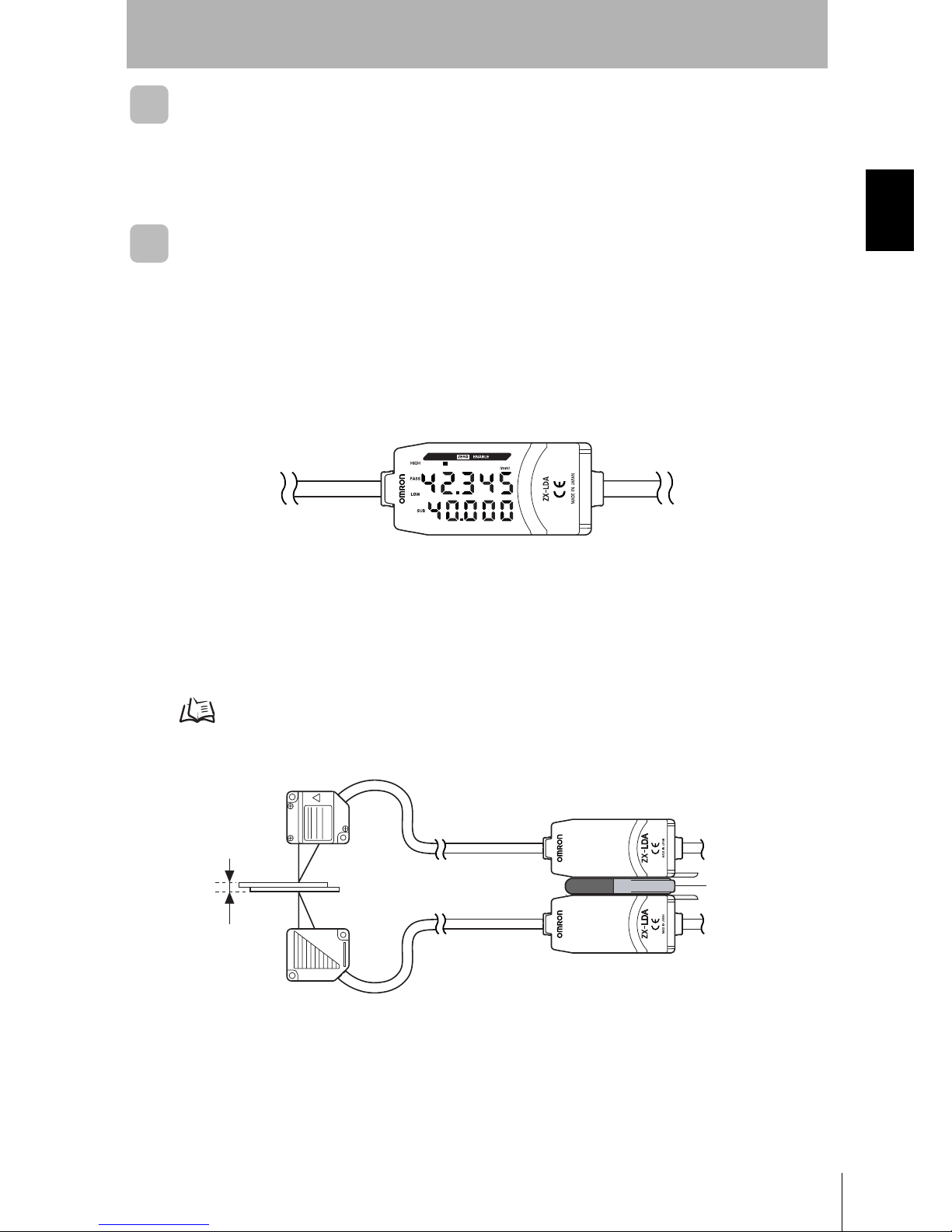
Connecting Amplifier Units
Connect two Amplifier Units by placing a Calculating Unit between them as shown in
the diagram.
The calculation result is displayed on (i.e., output to) the CH2 Amplifier Unit. Connect
the CH2 output cable to the external device to enable external control.
Connections p.21
The CH1 Amplifier Unit will display (output) the measurement result for the CH1 Sensor Head only.
If the Amplifier Units are connected, mutual interference between the Sensor Heads can also be
prevented.
Mounting Sensor Heads to Inspection Device
Mount the Sensor Heads to the steel plate in such a way that they face each other as
shown below.
Installing Sensor Heads p.18
Calculating Unit
CH1
CH2
Steel plate
Page 73

56
Section 4 Measuring Thickness
ZX-L-N
User’s Manual
Section 4
MAIN APPLICATIONS AND SETTING METHODS
Adjusting Setting Distances
Set a reference sample with a known thickness (T).
Adjust the position of the Sensor Heads so that the distances (A, B) between the
reference sample and the Sensor Heads are about the measuring center distance of
the corresponding Sensor Head. Refer to the Amplifier Unit's display while adjusting
the Sensor Head position.
Measuring range p.130
Setting Expressions
Position the reference sample and set the expression to calculate the thickness of the
reference sample.
The settings are made on the CH2 Amplifier Unit.
Select [THICK] as the expression type and enter the thickness (T) of the reference
sample.
When the thickness is entered, the positional relationship between the Sensor Heads
at that point will be registered. The thickness is measured based on the positional
relationship of the Sensor Heads.
Refer to Section 6 Auxiliary Functions for details on settings.
Performing Calculations p.108
T
B
A
T
Page 74

57
ZX-L-N
User’s Manual
Section 4 Measuring Thickness
Section 4
MAIN APPLICATIONS AND SETTING METHODS
Setting Tolerance Judgement Values
Set the upper and lower limits (HIGH and LOW thresholds) for the thickness for a PASS
(OK) judgement.
The HIGH, PASS, and LOW judgement results will be output based on the threshold
values set here.
Refer to Section 5 Detailed Settings for details on operation.
Inputting Threshold Values Directly p.89
Measurement Result Judgement
Measurement result > HIGH threshold HIGH
LOW threshold ≤ Measurement result ≤
HIGH threshold PASS
LOW threshold > Measurement result LOW
Page 75

58
Section 4 Measuring Eccentricity and Vibration
ZX-L-N
User’s Manual
Section 4
MAIN APPLICATIONS AND SETTING METHODS
Measuring Eccentricity and Vibration
This section describes, as an example, how to measure the eccentricity of a motor shaft.
Flow of Operation
Motor shaft
1
2
3
4
Mounting to
Device
Adjusting Setting
Position
Setting Tolerance
Judgement
Values
Measuring
Deflection
Page 76

59
ZX-L-N
User’s Manual
Section 4 Measuring Eccentricity and Vibration
Section 4
MAIN APPLICATIONS AND SETTING METHODS
Mounting to Device
Mount the Sensor Head to the inspection device.
When mounting the sensor, take care not to exert pressure on the sensor head and
wires.
Installing Sensor Heads p.18
Adjusting Setting Position
Adjust the position of the Sensor Head so that the distance (D) between the Sensor
Head and the sensing object is about the measuring center distance, as shown in the
diagram. Refer to the Amplifier Unit display while adjusting the Sensor Head position.
Measuring range p.130
D
Page 77

60
Section 4 Measuring Eccentricity and Vibration
ZX-L-N
User’s Manual
Section 4
MAIN APPLICATIONS AND SETTING METHODS
Measuring Deflection
Use the peak-to-peak hold function to measure the normal deflection.
Rotate the motor shaft, input a timing signal from an external device, and measure the
deflection.
The difference between the maximum and minimum measurement results (the
deflection) will be used as a reference when setting tolerances.
Refer to Section 5 Detailed Settings for details on settings.
Using Hold Functions p.76
Setting Tolerance Judgement Values
Refer to the deflection measured in step and set either the upper limit (HIGH
threshold) or lower limit (LOW threshold) for a PASS (OK) judgement.
The judgement result will be output based on the threshold value set here. The output
will depend on the type of threshold set.
Output when upper limit is set: PASS or HIGH
Output when lower limit is set: PASS or LOW
Refer to Section 5 Detailed Settings for details on operation.
Inputting Threshold Values Directly p.89
v
t
Measured value
Deflection
Timing input
Measurement Result Judgement
Measurement result > HIGH threshold HIGH
LOW threshold ≤ Measurement result ≤
HIGH threshold PASS
LOW threshold > Measurement result LOW
Page 78

61
ZX-L-N
User’s Manual
Section 4 Measuring Edges
Section 4
MAIN APPLICATIONS AND SETTING METHODS
Measuring Edges
This section describes, as an example, how to measure the edges of a rubber sheet.
Flow of Operation
Rubber sheet
1
2
3
4
5
Mounting to
Device
Setting Auto
Scale
Measuring
Reference
Samples
Setting the
Standard Received
Light Amount
Setting Tolerance
Judgement
Val ues
Page 79

62
Section 4 Measuring Edges
ZX-L-N
User’s Manual
Section 4
MAIN APPLICATIONS AND SETTING METHODS
Mounting to Device
Mount the Sensor Head to the inspection device.
When mounting the sensor, take care not to exert pressure on the sensor head and
wires.
Installing Sensor Heads p.18
Setting Auto Scale
Decide whether to display the received light amount in mm or in % in the Amplifier
Unit's main display.
Setting the Auto Scale p.42
Example: To display 5mm as the current input light amount (85%)
Setting the Standard Received Light Amount
With 100% laser input from the emitter to the receiver, set the standard received light
amount.
When the standard received light amount is set, the main display and linear outputs
(current, voltage) will be set to the full scale (F.S.) automatically.
Setting the Standard Received Light Amount p.45
Example: Setting the standard received light amount after setting auto scale to
[5-L] in step
(mm)
LDON ENABLEZERO
(mm)
LDON ENABLEZERO
Before auto scale is set Auto scale is set to [5-L].
Since 100% is equivalent to 5.000mm,
[4.250] will be displayed in the case of 85%.
2
(mm)
LDON ENABLEZERO
(mm)
LDON ENABLEZERO
Before the standard received light
amount is set
After the standard received light
amount is set
The current input light amount (85%) will be set to
the full scale (F.S.) and [5.000] will be displayed.
Page 80

63
ZX-L-N
User’s Manual
Section 4 Measuring Edges
Section 4
MAIN APPLICATIONS AND SETTING METHODS
Measuring Reference Samples
The edge of the reference sample is measured using position teaching and the
measurement result is registered as the HIGH threshold value.
The registered value becomes the reference for the threshold value set in step .
Refer to Section 5 Detailed Settings for details on settings.
Position Teaching p.90
The reference sample edge can also be set to 0.
Using the Zero Reset Function p.116
Setting Tolerance Judgement Values
Refer to the HIGH threshold registered in step and set the upper and lower limits
(HIGH and LOW thresholds) for a PASS (OK) judgement.
The HIGH, PASS, and LOW judgement results will be output based on the threshold
values set here.
Refer to Section 5 Detailed Settings for details on operation.
Inputting Threshold Values Directly p.89
Measurement Result Judgement
Measurement result > HIGH threshold HIGH
LOW threshold ≤ Measurement result ≤
HIGH threshold PASS
LOW threshold > Measurement result LOW
Page 81

64
Section 4
ZX-L-N
User’s Manual
Section 4
MAIN APPLICATIONS AND SETTING METHODS
MEMO
Page 82

Section 5 DETAILED SETTINGS
65
ZX-L-N
User’s Manual
Section 5
DETAILED SETTINGS
Setting Number of Samples to Average 66
Changing Display Scales 67
Setting the Measurement Sensitivity (Gain Switching) 74
Using Hold Functions 76
Comparing Measured Values (Differentiation Function) 83
Comparing Measured Values
(Previous Value Comparisons) 86
Entering Threshold Values 88
Linear Output 95
Setting Judgement Output Timing (Timer) 104
Page 83

66
Section 5 Setting Number of Samples to Average
ZX-L-N
User’s Manual
Section 5
DETAILED SETTINGS
Setting Number of Samples to Average
The average of the measured values obtained based on the preset number of samples can be
output. This setting can be used when you want to ignore rapid changes in measured values.
If this setting is made, response time for judgement and linear outputs will drop.
Moving to FUN mode and AVE
1. Set the mode switch to FUN.
2. Use the LEFT and RIGHT Keys to display
[AVE] on the main display.
Selecting Number of Samples to Average
3. Press the UP or DOWN Key.
The sub-display will flash.
4. Use the UP and DOWN Keys to select the
desired number of samples to average.
5. Press the ENT Key to confirm the setting.
The setting will be registered.
Selection for No. of
samples to average
Response time
1 0.3 ms
2 0.5 ms
4 0.8 ms
8 1.5 ms
16 2.5 ms
32 5 ms
64 10 ms
128 20 ms
256 40 ms
512 75 ms
1024 150 ms
2048 300 ms
4096 600 ms
In the case of Reflective Type Sensor Head, the
number of samples to average has been set to
256 prior to shipment from the factory.
In the case of Through-beam Type Sensor Head,
the number of samples to average has been set to
32 prior to shipment from factory.
In general, when the number of samples to average is
multiplied by “n”, the resolution will increase by .
n
(mm)
LD ON ENABLEZERO
SUB
SUB
SUB
Page 84

67
ZX-L-N
User’s Manual
Section 5 Changing Display Scales
Section 5
DETAILED SETTINGS
Changing Display Scales
Change the display scale when you want to display a value on the main display that is different
from the actual measured value.
Place an actual sensing object in position.
Two setting methods are available: one-point and two-point scaling methods.
• The scaling set here is reflected in the display only.
If you want to change the linear output of the displayed value, the monitor focus function must be used.
The minimum display value is -19999, and the maximum display value is 59999. Values (scaling
correction values) that exceed the minimum or maximum display value even if the object is located within
the measuring range cannot be set. An error will occur if such a value is set.
p.95
• To calculate the thickness, refer to “Performing Calculations” in “Measuring with Multiple Amplifier Units”.
p.108
Scaling Application Example
Purpose Method
To display the height of the sensing object
(Through-beam type sensor head)
Offset the display value. One-point
scaling
(Not
inverted.)
p.69
To display the height of the sensing object
(Reflective type sensor head)
Offset the display value and invert the
relationship between display and reference
values.
One-point
scaling
(Inverted)
p.69
Sensing
object
Height of sensing object
15mm
Light block width
6mm
Emitter Receiver
6
15
6
0
Displayed value
(mm)
Actual measured
value
(mm)
Sensor head
Sensing
object
Value to be
displayed
50mm
Actual measured
value
40mm
40
40
50
Displayed value
(mm)
Actual
measured
value
(mm)
Page 85

68
Section 5 Changing Display Scales
ZX-L-N
User’s Manual
Section 5
DETAILED SETTINGS
The settings listed below return to the default settings when scaling is set.
Make the settings for these items after scaling settings have been completed.
Self-trigger level, p.78
Monitor focus p.95
Zero Reset, p.116
Thickness setting (calculation) p.108
To correct display values to match actual
distances
(Reflective type sensor head)
Offset the display value and change the display
value range.
Two-point
scaling
p.72
To correct display values to match actual
distances
(Through-beam type sensor head)
Two-point
scaling
p.72
Scaling Application Example
Purpose Method
Sensor head
Actual distance: 40mm
Displayed value: 38mm
Sensing
object
Sensing
object
Actual distance: 32mm
Displayed value: 33mm
Sensor head
40
38
33
32
32 40
Displayed value
(mm)
Actual
measured
value
(mm)
Sensing
object
Emitter Receive
Emitter Receiver
Sensing
object
Actual distance: 2.5mm
Displayed value: 2mm
Actual distance: 8mm
Displayed value: 7mm
2.5 8
2
2.5
7
8
Displayed value
(mm)
Actual
measured
value
(mm)
Page 86

69
ZX-L-N
User’s Manual
Section 5 Changing Display Scales
Section 5
DETAILED SETTINGS
One-point Scaling
Measurement is performed at one position and offset values are set for that
measurement.
The offset and increment/decrement inversion (display inversion) can be set.
This section describes how to set one-point scaling, using an example of correcting
display values to match actual distances.
Example: Displaying the Height of the Sensing Object
Moving to FUN Mode and SCALE
1. Set the mode switch to FUN.
2. Use the LEFT and RIGHT Keys to display
[SCALE] on the main display.
Executing Scaling
3. Press the UP or DOWN Key.
The sub-display will flash.
4. Use the UP and DOWN Keys to display [ON].
40
40
50
Sensing
object
Displayed value
(mm)
Actual measured
value
(mm)
Actual measured
value
40mm
Sensor head
Value to be
displayed
50mm
(mm)
LD ON ENABLEZERO
SUB
SUB
Page 87

70
Section 5 Changing Display Scales
ZX-L-N
User’s Manual
Section 5
DETAILED SETTINGS
5. Press the ENT Key to confirm the setting.
The sub-display will show [P1SCL].
6. Set the sensing object at the position where
the display value change is required.
Set the sensing object within the measurement distance. The ENABLE indicator will be lit when the
sensing object is within the measurement distance. Scaling is not possible if the sensing object is
not within the distance.
7. Press any Cursor Key.
The current measured value will be displayed on the
main display.
The leftmost digit of the sub-display will flash.
8. Use the Cursor Keys to set the offset for the
measured value in the sub-display.
The position of the decimal point can be changed using
the next steps.
9. Press the ENT Key to confirm the setting.
The decimal point will flash.
10. Use the LEFT and RIGHT Keys to change
the position of the decimal point, if necessary.
11. Press the ENT Key to confirm the setting.
The inverted display settings will appear on the sub-
display.
SUB
(mm)
LD ON ENABLEZERO
SUB
(mm)
LD ON ENABLEZERO
Moves from one digit to
another.
Changes the current value.
SUB
SUB
Page 88

71
ZX-L-N
User’s Manual
Section 5 Changing Display Scales
Section 5
DETAILED SETTINGS
Selecting Inverted Display
12. Use the UP and DOWN Keys to select the
inverted display function.
13. Press the ENT Key to confirm the setting.
The sub-display will be [P2SCL].
14. Press the ENT Key.
Confirming that Scaling Is Completed
If scaling has been completed correctly, the display will
be [OK].
If scaling was unable to be completed, the display will be
[NG].
Check that the sensing object is within the measurement
range and execute scaling again.
Selection Details
D-FWD Not inverted.
The larger the distance between the Sensor
Head and the object, the larger the measured
value displayed on the Amplifier Unit.
D-INV Inverted
The larger the distance between the Sensor
Head and the object, the smaller the
measured value displayed on the Amplifier
Unit.
SUB
SUB
SUB
(mm)
LD ON ENABLEZERO
SUB
(mm)
LD ON ENABLEZERO
Page 89

72
Section 5 Changing Display Scales
ZX-L-N
User’s Manual
Section 5
DETAILED SETTINGS
Two-point Scaling
Measurement is performed at two positions and offset values are set for those
measurements.
Both an overall offset can be set and the range can be changed.
This section describes how to set two-point scaling, using an example of correcting
display values to match actual distances.
Example: Correcting Display Values to Match Actual Distances
Separate the two specified points by at least 1% of the rated measurement range for the connected
Sensor.
For example, the rated measurement range for the ZX-LD40 Sensor is 20 mm. Therefore, the two
specified points must be separated by 0.2 mm min.
Setting the First Point
1. Set the first point by following steps 1. to 11.
of the one-point scaling procedure.
p.69
The range for two-point scaling is automatically
set based on the values entered for the two
points. Inverted display settings are ignored.
40
38
33
32
32 40
Displayed
value
(mm)
Actual measured
value (mm)
Sensor head
Sensing
object
Sensing
object
Sensor head
Actual distance: 32mm
Displayed value: 33mm
Actual distance: 40mm
Displayed value: 38mm
Page 90

73
ZX-L-N
User’s Manual
Section 5 Changing Display Scales
Section 5
DETAILED SETTINGS
Setting the Second Point
2. Place the sensing object in the position for which the display is to be changed (the
second point).
The sensing object must be set at a distance at
least 1% of the rated measurement range away
from the first point and also at a distance within
the measurement range.
3. Press any Cursor Key.
The current measured value will be displayed on the
main display.
The leftmost digit of the sub-display will flash.
4. Use the Cursor Keys to set the offset for the
measured value.
The position of the decimal point can be changed using
the next steps.
5. Press the ENT Key to confirm the setting.
The decimal point will flash.
6. Use the LEFT and RIGHT Keys to move the
decimal point.
7. Press the ENT Key to confirm the setting.
Confirming the Completion of the Scaling Settings
If scaling has been completed correctly, the display will
be [OK].
If scaling was unable to be completed, the display will be
[NG].
Check the following points and then execute scaling
again.
• Is the sensing object within the measurement range?
• Are the two points separated by at least 1% of the
rated measurement range?
SUB
(mm)
LD ON ENABLEZERO
Moves from one digit to
another.
Changes the current value.
SUB
SUB
(mm)
LD ON ENABLEZERO
SUB
(mm)
LD ON ENABLEZERO
Page 91

74
Section 5 Setting the Measurement Sensitivity (Gain Switching)
ZX-L-N
User’s Manual
Section 5
DETAILED SETTINGS
Setting the Measurement Sensitivity (Gain Switching)
This section describes how to set the measurement gain according to the surface condition of
the sensing object.
Setting the measurement gain to AUTO will automatically adjust the sensitivity to the optimum
level for the object.
If the amount of reflective sensor light on the object does not change excessively, stable
measurements can be carried out by fixing the measurement gain to an appropriate one.
Five measurement gains are available: [AUTO] for automatic adjustment, and [BLACK],
[WHITE], [METAL] and [MIROR], which are fixed measurement gains. In the case of fixed
measurement gains, the measurement sensitivity increases in the order [MIROR], [METAL],
[WHITE], [BLACK], [MIROR] with the lowest measurement sensitivity and [BLACK] with the
highest measurement sensitivity.
For [AUTO] measurement gain
For fixed measurement gains (other than [AUTO])
AUTO can be set only when the Sensor Head is the Reflective type and the intensity mode is disabled.
Intensity mode p.46
Moving to FUN Mode and SPCL
1. Set the mode switch to FUN.
2. Use the LEFT and RIGHT Keys to display
[SPCL] on the main display.
When the received light
amount is not sufficient
When the received light
amount is excessive
Large gain Small gain
Switched
automatically
When the received light
amount is not sufficient
When the received light
amount is appropriate
When the received light
amount is excessive
Saturated
received light
amount
(An error occurs,
and the main
display will show
[E-BRT].)
Within
allowable
received light
amount
range
(Measurement
possible)
Insufficient
received light
amount
(An error
occurs, and the
main display
will show
[E-DRK].)
(mm)
LD ON ENABLEZERO
Page 92

75
ZX-L-N
User’s Manual
Section 5 Setting the Measurement Sensitivity (Gain Switching)
Section 5
DETAILED SETTINGS
Moving to GAIN
3. Press the UP or DOWN Key.
The sub-display will flash.
4. Use the UP and DOWN Keys to display
[ETC] or [ALL].
5. Press the ENT Key.
6. Use the LEFT and RIGHT Keys to display
[GAIN] on the main display.
Setting the Measurement Gain
7. Press the UP or DOWN Key.
The sub-display will flash.
8. Select the desired measurement gain.
9. Press the ENT Key to confirm the setting.
The selected measurement gain will be set.
SUB
SUB
SUB
(mm)
LD ON ENABLEZERO
SUB
SUB
SUB
Page 93

76
Section 5 Using Hold Functions
ZX-L-N
User’s Manual
Section 5
DETAILED SETTINGS
Using Hold Functions
The hold functions hold data for specific points during the measurement period, such as the
maximum or minimum value, and output those values at the end of the measurement period.
Flow of Operation
Selecting Hold Condition for Measured Values
The time period from the start of hold measurements to the end of hold measurements
is called the sampling period.
The value to be held during that sampling period is selected here.
The CLAMP value is output until the first sampling period is finished.
CLAMP value p.102
Any of the 5 settings shown in the table can be selected as the value to hold.
1
2
3
Selecting Hold
Condition for
Measured Values
Setting the Trigger
for Measurement in
Hold Mode
Setting Delay Time
(If required)
Selection Details
OFF
(Default)
Hold measurement is not performed. The measured value is always output.
P-H (Peak hold) Holds the maximum value during the sampling period. The output changes at the
end of the sampling period and is held until the end of the next sampling period.
B-H (Bottom hold) Holds the minimum value during the sampling period. The output changes at the
end of the sampling period and is held until the end of the next sampling period.
Current
measured value
Maximum
value
Sampling period
Output
Current
measured value
Minimum
value
Sampling period
Output
Page 94

77
ZX-L-N
User’s Manual
Section 5 Using Hold Functions
Section 5
DETAILED SETTINGS
Moving to FUN mode and HOLD
1. Set the mode switch to FUN.
2. Use the LEFT and RIGHT Keys to display
[HOLD] on the main display.
Selecting Hold Condition
3. Press the UP or DOWN Key.
The sub-display will flash.
4. Use the UP and DOWN Keys to select the
desired hold condition.
5. Press the ENT Key to confirm the setting.
The setting will be registered.
PP-H (Peak-to-peak
hold)
Holds the difference between the maximum and minimum values. This option is
selected mainly when detecting vibration. The output changes at the end of the
sampling period and is held until the end of the next sampling period.
S-H (Sample hold) Holds the measured value at the start of the sampling period. The output
changes at the start of the sampling period and is held until the start of the next
sampling period.
AVE-H (Average hold) Holds the average measured value during the sampling period. The output
changes at the end of the sampling period and is held until the end of the next
sampling period.
Selection Details
Sampling period
Current
Maximum
value
Minimum
value
Output (maximum value
- minimum value)
Sampling period
Current
measured value
Output
Sampling period
Current
measured value
Output (average of
measured values)
(mm)
LD ON ENABLEZERO
SUB
SUB
SUB
Page 95

78
Section 5 Using Hold Functions
ZX-L-N
User’s Manual
Section 5
DETAILED SETTINGS
Setting the Trigger for Measurement in Hold Mode
Select the input method for the timing of the start and end of the measurement period.
• Set the hysteresis width based on the fluctuations in the measured values around the trigger
level. The hysteresis will be applied from the start of the sampling period and will prevent timing
input chattering.
• Zero reset input will be invalid during sampling or while [-----] is displayed in the main display.
• The timing input signal will be ignored if the self-trigger level is set to [UP] or [DOWN]. However,
sampling will not be affected.
Selection Details
TIMIG
(Timing input)
(Default)
Enter the trigger for the start of sampling by using the timing input. The period
that the timing signal is ON is the sampling period.
When a delay time is set, the input OFF timing and the end of the
sampling period will not be synchronous. Sampling will end after the
specified sampling period has expired.
UP
(Self-up trigger)
The sampling period is the period that the measured value is greater than the
specified self-trigger level. Hold measurement is possible without a sync input.
When a delay time is set, the timing when the measured value becomes
smaller than the self-trigger level and the end of the sampling period will
not be synchronous. Sampling will end after the specified sampling
period has expired.
DOWN
(Self-down trigger)
The sampling period is the period that the measured value is lower than the
specified self-trigger level. Hold measurement is possible without a sync input.
When a delay time is set, the timing when the measured value becomes
greater than the self-trigger level and the end of the sampling period will
not be synchronous. Sampling will end after the specified sampling
period has expired.
ON
OFF
Sampling period
Timing input
Sampling period Sampling period
Self-trigger
level
Measured
value
Operation point
Hysteresis width
(For self-trigger)
Return point
Self-trigger
level
Measured
value
Sampling period
Operation point
Return point
Hysteresis width
(For self-trigger)
Page 96

79
ZX-L-N
User’s Manual
Section 5 Using Hold Functions
Section 5
DETAILED SETTINGS
Selecting Trigger Types
1. Use the LEFT and RIGHT Keys to display
[H-TRG] on the main display.
[H-TRG] will not be displayed if the delay conditions are
set to OFF.
2. Press the UP or DOWN Key.
The sub-display will flash.
3. Use the UP or DOWN Key to select the
desired trigger type.
4. Press the ENT Key to confirm the setting.
The selected trigger type will be registered.
Setting Trigger Levels (when UP or DOWN Is Selected)
5. Use the RIGHT or LEFT Key to display
[H-LVL] on the main display.
[H-LVL] will not be displayed if timing input [TIMIG] is set
as the trigger.
6. Press the UP or DOWN Key.
The leftmost digit of the sub-display will flash.
7. Use the Cursor Keys to set the desired trigger
level.
8. Press the ENT Key to confirm the setting.
The trigger level will be registered.
(mm)
LD ON ENABLEZERO
SUB
SUB
SUB
(mm)
LD ON ENABLEZERO
SUB
Moves from one digit to
another.
Changes the current value.
SUB
Page 97

80
Section 5 Using Hold Functions
ZX-L-N
User’s Manual
Section 5
DETAILED SETTINGS
Setting Hysteresis Width (when UP or DOWN Is Selected)
9. Use the LEFT and RIGHT Keys to display
[H-HYS] on the main display.
[H-HYS] will not be displayed if timing input [TIMIG] is set
as the trigger.
10. Press the UP or DOWN Key.
The leftmost digit of the sub-display will flash.
11. Use the Cursor Keys to set the hysteresis
width for the trigger level.
12. Press the ENT Key to confirm the setting.
The hysteresis width will be registered.
(mm)
LD ON ENABLEZERO
SUB
Moves from one digit to
another.
Changes the current value.
SUB
Page 98

81
ZX-L-N
User’s Manual
Section 5 Using Hold Functions
Section 5
DETAILED SETTINGS
Setting Delay Time
Delay time is set to ignore measurements immediately after the timing input. This is
useful for avoiding bounding during device startup and the influence of machine
vibration.
The delay time (the delay between timing input and the start of sampling) and the
sampling period can be set.
The default delay time setting is [OFF].
Make the sum of the delay time and sampling period less than the timing input ON interval.
If the next timing input for measurement is received before the delay and sampling period have
passed, that timing input will be ignored and will not be reflected in the sampling.
Moving to Delay Hold (H-DLY)
1. Use the LEFT and RIGHT Keys to display
[H-DLY] on the main display.
[H-DLY] will not be displayed if the delay conditions are
set to [OFF].
2. Press the UP or DOWN Key.
The sub-display will flash.
3. Use the UP and DOWN Keys to display [ON].
4. Press the ENT Key.
The settings mode for the H-DLY function is now
enabled.
ON
OFF
Ignored Accepted
Delay time
Sampling period
Delay time
Timing input
(mm)
LD ON ENABLEZERO
SUB
SUB
SUB
Page 99

82
Section 5 Using Hold Functions
ZX-L-N
User’s Manual
Section 5
DETAILED SETTINGS
Setting Delay Time
5. Use the LEFT and RIGHT Keys to display
[H-D-T] on the main display.
[H-D-T] will not be displayed if the H-DLY function is set
to [OFF].
6. Press the UP or DOWN Key.
The leftmost digit of the sub-display will flash.
7. Enter the delay time (ms).
8. Press the ENT Key to confirm the setting.
The delay time will be registered.
Setting the Sampling Period
9. Use the LEFT and RIGHT Keys to display
[H-S-T] on the main display.
[H-S-T] will not be displayed if the H-DLY function is set
to [OFF].
10. Press the UP or DOWN Key.
The leftmost digit of the sub-display will flash.
11. Use the Cursor Keys to enter the sampling
period (ms).
12. Press the ENT Key to confirm the setting.
The sampling period will be registered.
(mm)
LD ON ENABLEZERO
SUB
Moves from one digit to
another.
Changes the current value.
SUB
(mm)
LD ON ENABLEZERO
SUB
Moves from one digit to
another.
Changes the current value.
Page 100

83
ZX-L-N
User’s Manual
Section 5 Comparing Measured Values (Differentiation Function)
Section 5
DETAILED SETTINGS
Comparing Measured Values (Differentiation
Function)
Use the differentiation function to detect only sudden changes in the measured values that
occur during very short periods of time.
The differentiation function detects changes between the present value and the measured
value that is in effect just before the comparing pitch. The coefficient of this comparing pitch is
defined as the differentiation cycle.
The relationship between the differentiation cycle and comparing pitch can be calculated by
the following equation.
Comparing pitch = Differentiation cycle x 150µs
Example: When differentiation cycle = 10
If you want to detect changes in hold value, use the previous value comparison function.
Previous value comparison p.86
Moving to FUN Mode and SPCL
1. Set the mode switch to FUN.
2. Use the LEFT and RIGHT Keys to display
[SPCL] on the main display.
Present value
Sampling
Comparing pitch 1.5ms (150µs x 10)
Displayed value
(Differentiation
result)
Sampling time
(150µs)
(mm)
LD ON ENABLEZERO
 Loading...