

Omron K2CU-F10A-CGS, K2CU-F80A-CGS, K2CU-F20A-CGS, K2CU-F40A-CGS, K2CU-F10A-DGS User Manual
...Page 1
1
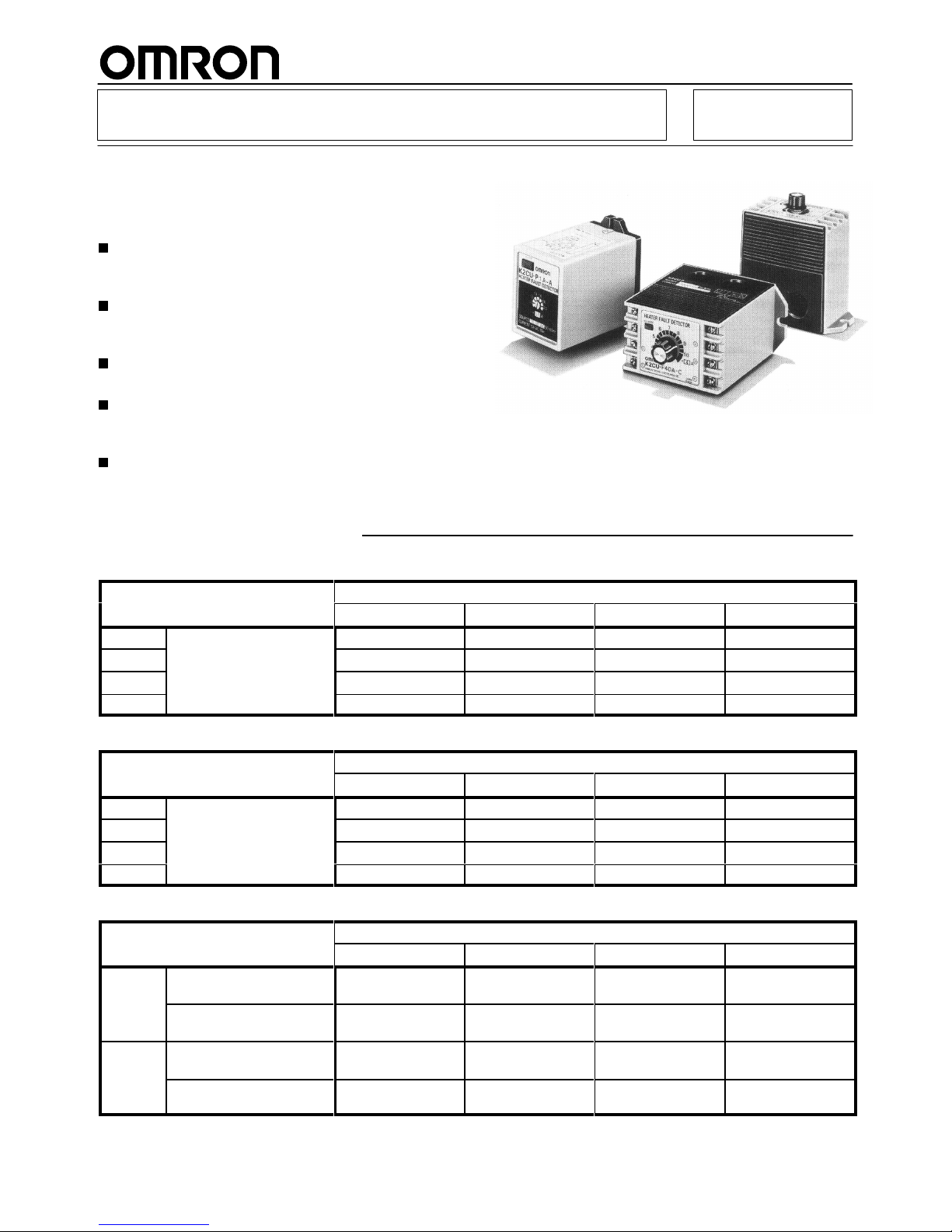
Heater Element Burnout Detector
K2CU
Accurate Detection of Heater Element
Burnout Regardless of Heater
Capacities
Accurately detects a burned heater element or
elements incorporated by a molding machine or
packing machine and outputs an alarm signal.
Precisely singles out the burned element even if
one heater element among several heater
elements has been burned out.
Applicable to small- to large-capacity heater
elements.
All K2CU-F large-capacity, built-in current transformer models work with both single-phase and
three-phase heaters.
Voltage fluctuation compensation function eliminates false alarms due to variations in the supply
voltage.
Ordering Information
K2CU-FjjA-jGS Model with Gate Input Terminals
Control
supply voltage
Operating current
4 to 10 A 8 to 20 A
16 to 40 A 32 to 80 A
100 V
AC W
ith voltage fluctuation
K2CU-F10A-CGS K2CU-F20A-CGS K2CU-F40A-CGS K2CU-F80A-CGS
1
10 V
AC compensation K2CU-F10A-DGS K2CU-F20A-DGS K2CU-F40A-DGS K2CU-F80A-DGS
200 V
AC K2CU-F10A-EGS K2CU-F20A-EGS K2CU-F40A-EGS K2CU-F80A-EGS
220 V
AC K2CU-F10A-FGS K2CU-F20A-FGS K2CU-F40A-FGS K2CU-F80A-FGS
K2CU-F Large-capacity, Built-in Current Transformer Models
Control
supply voltage
Operating current
4 to 10 A 8 to 20 A
16 to 40 A 32 to 80 A
100 V
AC W
ith voltage fluctuation
K2CU-F10A-C K2CU-F20A-C K2CU-F40A-C K2CU-F80A-C
1
10 V
AC compensation K2CU-F10A-D K2CU-F20A-D K2CU-F40A-D K2CU-F80A-D
200 V
AC K2CU-F10A-E K2CU-F20A-E K2CU-F40A-E K2CU-F80A-E
220 V
AC K2CU-F10A-F K2CU-F20A-F K2CU-F40A-F K2CU-F80A-F
K2CU-P Small-capacity, Plug-in Models
Control
supply voltage
Operating current
0.25 to 0.5 A
0.5 to 1 A
1 to 2 A 2 to 4 A
100/
200 V
AC
W
ith voltage fluctuation
compensation
K2CU-P0.5A-A K2CU-P1A-A K2CU-P2A-A K2CU-P4A-A
W
ithout voltage
fluctuation compensation
--- K2CU-P1-A K2CU-P2-A K2CU-P4-A
110/
220 V
AC
W
ith voltage fluctuation
compensation
K2CU-P0.5A-B K2CU-P1A-B K2CU-P2A-B K2CU-P4A-B
W
ithout voltage
fluctuation compensation
--- K2CU-P1-B K2CU-P2-B K2CU-P4-B
Page 2

K2CU
K2CU
2
Specifications
Ratings
Item K2CU-F K2CU-P
Control
supply voltage
100, 1
10, 200, 220 V
AC
100/200, 1
10/220 V
AC
Rated frequency
50/60 Hz
Carry current
1.25 times as large as each model’
s
maximum operating current
2.5 A for K2CU-P0.5A-A/-B;
5 A
Operating voltage range
85% to 1
10% of control supply voltage
V
oltage fluctuation compensation
range
85% to 1
10% of control supply voltage
85% to 1
10% of control supply voltage
(applicable only on models with voltage
fluctuation compensation)
Operating current
4 to 10 A, 8 to 20 A, 16 to 40 A, 32 to 80 A
(continuously variable)
0.25 to 0.5 A, 0.5 to 1 A, 1 to 2 A, 2 to 4 A
(continuously variable)
Releasing current
105% max. of operating current
1
10% max. of operating current
Operate time
0.5 s max. (when current changes from 150% to 0%)
Gate input voltage range (for
models with gate input terminals)
5 to 30 VDC
---
Control output
2 A at 220 V
AC, SPDT (cosφ
= 0.4)
Power consumption
Input: 0.5 V
A max.
Power supply: 5 V
A max.
Input: 1 V
A max.
Power supply: 4 V
A max.
Characteristics
Setting
accuracy
±
7% max.
Repeat accuracy
±
3% max.
Influence of temperature
±
10% max. (at 20
°C±30°C)
Influence of voltage
Models without voltage fluctuation compensation:
±
3% max. of the value measured at the control supply voltage, on condition that the voltage
fluctuation is 85% to 1
10% of the control supply voltage
Models with voltage fluctuation compensation:
±
5% max. of the logical value, on condition that the voltage fluctuation is 85% to 1
10% of the
control supply voltage. (see note)
Influence of frequency
±
3% max. (at ±5% of rated frequency)
Insulation resistance
10 MΩ min. (at 500 VDC) between electric circuits and mounting panel
Dielectric strength
2,000 V
AC, 50/60 Hz for 1 min between electric circuits and mounting panel
Overcurrent
20 times of max. set value of operating current for 2 s
V
ibration resistance
Destruction: 16.7 Hz, 1-mm double amplitude for 10 min each in X, Y
, and Z directions
Shock resistance
Destruction: 100 m/s2 (approx. 10G)
Ambient temperature
Operating: –10°C to 55°C (with no icing)
Ambient humidity
Operating: 45% to 85%
Weight
K2CU-F: approx. 390 g; K2CU-P: approx. 300 g
Note: The
logical value is an operating value within a range of 0.85 to 1.1 with a voltage fluctuation of 85% to 1
10%, based on the value at the
control
supply voltage measured as 1.
Page 3
K2CU
K2CU
3
Operation
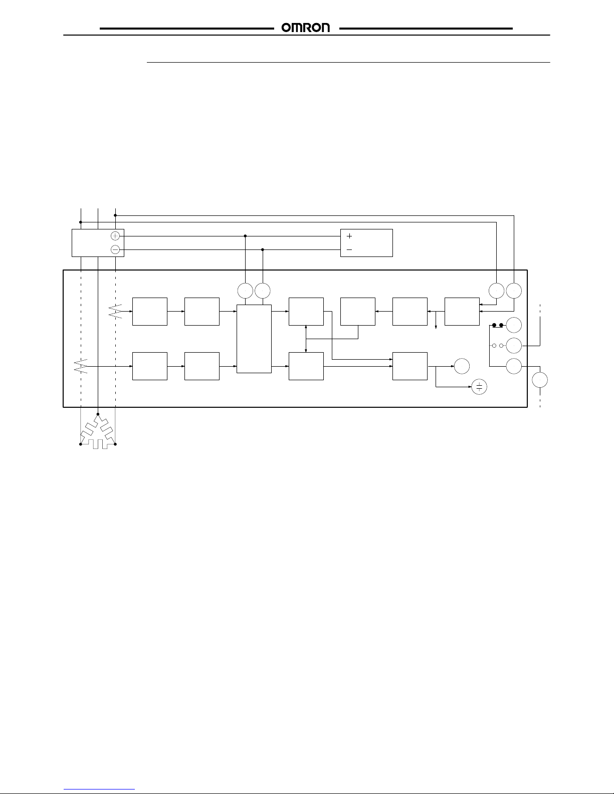
K2CU-F A- GS
Series
When
power is supplied to the heater (when the SSR is ON), a cur
rent flows through the wires to the heater elements. At the same
time, a voltage is imposed on the gate circuit and the
K2CU-FjjAjGS begins monitoring the current flowing through
the
heater wires.
The current flowing to the heater wires is detected by the detector
sections through each Current Transformer (CT) incorporated by
the K2CU-FjjA-jGS.
The
current signals transmitted by the two CT
s are sent to the cur
rent-voltage converters, smoothing circuits, and comparators as
shown
in the diagram.
The
signal generated by the reference voltage generator is sent to
the
setting circuit to provide a reference value. The reference value
is sent to the comparators. Each comparator compares its heater
element
current input
and the reference value. If the input is lower
than the reference value, a signal is sent to the output circuit.
There
are two
detector sections operating independently
. If either of
the
input signals from the CT
s is lower than the reference value, the
output
relay and alarm indicator will be activated.
The K2CU-FjjA-jGS incorporates a voltage fluctuation compensation
function which automatically corrects the reference value
if
the supply voltage fluctuates.
Currentvoltage
converter
Smoothing
circuit
Gate
circuit
Setting
circuit
Reference
voltage
generator
Power
circuit
Currentvoltage
converter
Smoothing
circuit
BZ
Output
circuit
Temperature
controller
X CM1
a1
b1
S2S1G–G+
CT
1
CT
2
SSR DC
Heater elements
Power source
X/c
Output relay
Alarm indicator
Buzzer
To each circuit
Note: 1. The
dotted lines indicate the line conductors passing through the windows of the current transformers.
2.
The current flowing into the gate circuit (between G+ and G–) is as follows:
Approximately 1.4 mA at 5 VDC
Approximately 3.4 mA at 12 VDC
Approximately 6.7 mA at 24 VDC
3
When using a K2CU which has the model number suf
fix ”GS” (a model that incorporates gate input
terminals), the control output of the temperature controller must be a voltage output type.
Comparator
Comparator
Page 4
K2CU
K2CU
4
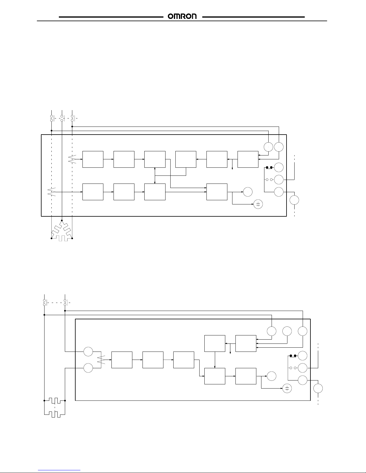
K2CU-F
Series
When
power is supplied to the heater (when the contactor
is ON), a
current flows through the wires to the heater elements. At the same
time,
a voltage is imposed on the power circuit of the K2CU-F
.
The current flowing to the heater wires is detected by the detector
sections through each Current Transformer (CT) incorporated by
the K2CU-F.
The
current signals transmitted by the two CT
s are sent to the cur
rent-voltage converters, smoothing circuits, and comparators as
shown
in the diagram.
The
signal generated by the reference voltage generator is sent to
the
setting circuit to provide a reference value. The reference value
is sent to the comparators. Each comparator compares its heater
element
current input
and the reference value. If the input is lower
than the reference value, a signal is sent to the output circuit.
There
are two
detector sections operating independently
. If either of
the
input signals from the CT
s is lower than the reference value, the
output
relay and alarm indicator will be activated.
The
K2CU-F incorporates a voltage
fluctuation compensation func
tion which automatically corrects the reference value if the supply
voltage
fluctuates.
Currentvoltage
converter
Smoothing
circuit
Setting
circuit
Reference
voltage
generator
Power
circuit
Currentvoltage
converter
Smoothing
circuit
BZ
Output
circuit
X CM1
a1
b1
S2S1
CT
1
CT
2
Heater elements
Power source
X/c
Output relay
Alarm indicator
Buzzer
To each circuit
Comparator
Comparator
Note: The
dotted lines indicate the line conductors passing through the windows of the current transformers.
Contactor
K2CU-P
Series
The
K2CU-P operates basically in the same way as the K2CU-F
.
The comparator compares external current signals and the reference value and outputs the result of the comparison to the output
circuit.
Currentvoltage
converter
Smoothing
circuit
Setting
circuit
Power
circuit
BZ
Output
circuit
X
3
4
5
87
Comparator
Reference
voltage
generator
Heater elements
Power source
X/c
Output relay
Alarm indicator
To each circuit
Contactor
6
Buzzer
CT
1
2
200/220 V 100/110 V 0 V
Page 5
K2CU
K2CU
5
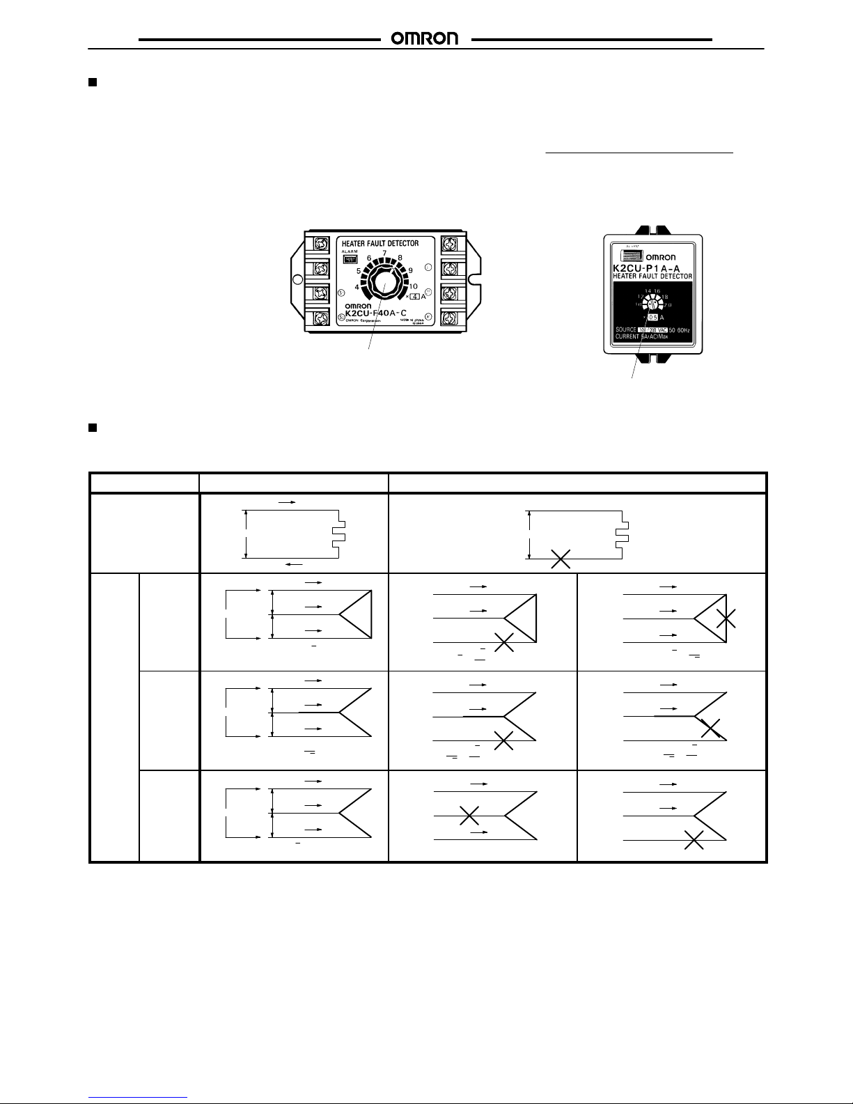
Setting of Operating Current
Use the potentiometer on the front panel to set the operating current.
Rotate
the knob to set the desired current value at which the
Heater
Burnout
Detector should operate. Do
not exceed the maximum and
minimum
positions.
The K2CU-F’s scale is divided into 12 graduations including subgraduations
and the K2CU-P’
s scale is divided into 5 graduations.
The
knobs of
the K2CU-F and K2CU-P as shown in the illustrations
are
set to 32 A and 0.7 A respectively
.
The
set operating current is defined as the mean value
of the heater
current under normal operating conditions and the heater current
under
a burnout or abnormal condition.
Set value =
Normal current + abnormal current
2
Knob
Red point
(indicates the set value)
Heater Connection and Current
The
following table shows the dif
ferent connections possible. The formula under each illustration indicates the electrical current value of
the
heater
elements under normal and abnormal conditions.
Phase
Normal condition
Abnormal condition
Single phase
200 V
5 A
5 A
1 kW
200 V
0 A
0 A
Three
phase
Delta
network
200 V
200 V
200 V
8.7 A
8.7 A
8.7 A
1 kW
1 kW
1 kW
(5 A x )
3
7.5 A
7.5 A
3
2
(5 A x x )
3
5 A
8.7 A
5 A
1
3
(5 A x x )
3
Star
network
200 V
200 V
200 V
2.9 A
2.9 A
2.9 A
1 kW
1 kW
1 kW
1
3
(5 A x )
2.5 A
2.5 A
3
2
(5 A x x )
1
3
2.5 A
2.5 A
3
2
(5 A x x )
1
3
V
network
200 V
200 V
200 V
5 A
8.7 A
5 A
1 kW
1 kW
(5 A x = 8.7 A)
3
(5A x 1/2)
2.5 A
2.5 A
5 A
5 A
(5A x 1)
Note: Values
in this table are correct when a 200 V
AC, 1 kW heater is used on a single-phase or three-phase current.
Page 6

K2CU
K2CU
6
Operation Check
K2CU-F A- GS
The
operation of the heater burnout detector can be easily
checked
as
follows:
In a Single-phase Circuit
Set
the operating current to be 0.6 to 0.55 times the heater current.
Close the SW2 with switch SW1 turned on. Confirm that the alarm
indicator remains of
f.
Turn
of
f SW1 and confirm that the alarm indicator comes on, and that
the
output relay operates.
K2CU-F
S1
S2
G+
G–
Heater
SW
1
SSR
SW
2
In a Three-phase, Delta Network
Set the operating current to be 0.6 times the heater current.
Close
the SW3 with switches SW1 and SW2 turned
on. Confirm that
the
alarm indicator remains of
f.
Turn
of
f SW2 and confirm that the alarm indicator comes on, and that
the
output relay operates.
Turn
on SW1 set the operating current to be 0.9 times the heater cur
rent, and confirm that the alarm indicator goes off and the output
relay
releases.
Turn
of
f SW1 and confirm that the alarm indicator comes on, and that
the
output relay operates.
G+
G–
S1
S2
K2CU-F
Heater
SW
1
SSR
SW
3
SW
2
In a Three-phase, Star Network
Set the operating current to be 0.9 times the heater current.
Close the SW2 with switch SW1 turned on. Confirm that the alarm
indicator remains of
f.
Turn
of
f SW1 and confirm that the alarm indicator comes on, and that
the
output relay operates.
G+
G–
S1
S2
K2CU-F
Heater
SW
1
SSR
SW
2
Page 7
K2CU
K2CU
7
In a Three-phase, V Network 1
Set
the operating current to be 0.3 to 0.35 times the heater current.
Close the SW2 with switch SW1 turned on. Confirm that the alarm
indicator remains of
f.
Turn off SW1 and confirm that the alarm indicator comes on, and
that
the output relay operates.
G+
G–
S1
S2
K2CU-F
Heater
SW
1
SSR
SW
2
In a Three-phase, V Network 2
Set
the operating current to be 0.6 times the heater current (of
the
phase connected between terminals 1 and 2, or the one passed
through
the window
of the window-type Current T
ransformer of the
heater
burnout detector).
Close the SW2 with switch SW1 turned on. Confirm that the alarm
indicator remains of
f.
Turn off SW1 and confirm that the alarm indicator comes on, and
that
the output relay operates.
G+
K2CU-F
Heater
SSR
SW
2
SW
1
G–
S1
S2
K2CU-F, K2CU-P
The
operation of the heater burnout detector can be easily
checked
as
follows:
In a Single-phase Circuit
Set
the operating current to be 0.55 to 0.6 times the heater current.
Close the contactor with switch SW1 turned on. Confirm that the
alarm
indicator remains of
f.
Turn
of
f SW1 and confirm that the alarm indicator comes on, and that
the
output relay operates.
K2CU-F
S1
S2
Heater
SW
1
1
2
K2CU-P
Heater
SW
1
Contactor
Contactor
Page 8

K2CU
K2CU
8
In a Three-phase, Delta Network
Set the operating current to be 0.6 times the heater current.
Close
the contactor with switches SW1 and SW2 turned on. Confirm
that
the alarm indicator remains of
f.
Turn
of
f SW2 and confirm that the alarm indicator comes on, and that
the
output relay operates.
Turn
on SW1 set the operating current to be 0.9 times the heater cur
rent, and confirm that the alarm indicator goes off and the output
relay
releases.
Turn
of
f SW1 and confirm that the alarm indicator comes on, and that
the
output relay operates.
S1
S2
K2CU-F
Heater
SW
2
SW
1
Contactor
In a Three-phase, Star Network
Set the operating current to be 0.9 times the heater current.
Close the contactor with switch SW1 turned on. Confirm that the
alarm
indicator remains of
f.
Turn
of
f SW1 and confirm that the alarm indicator comes on, and that
the
output relay operates.
Heater
S1
S2
K2CU-F
SW
1
Contactor
In a Three-phase, V Network 1
Set
the operating current to be 0.3 to 0.35 times the heater current.
Close the contactor with switch SW1 turned on. Confirm that the
alarm
indicator remains of
f.
Turn off SW1 and confirm that the alarm indicator comes on, and
that
the output relay operates.
S1
S2
Heater
K2CU-F
SW
1
Contactor
In a Three-phase, V Network 2
Set
the operating current to be 0.6 times the heater current (of
the
phase connected between terminals 1 and 2, or the one passed
through
the window
of the window-type Current T
ransformer of the
heater
burnout detector).
Close the contactor with switch SW1 turned on. Confirm that the
alarm
indicator remains of
f.
Turn off SW1 and confirm that the alarm indicator comes on, and
that
the output relay operates.
SW
1
Contactor
1
2
K2CU-P
Heater
K2CU-P
Page 9

K2CU
K2CU
9
S1
S2
Heater
K2CU-F
SW
1
Contactor
K2CU-F
Test Circuit
To
check the operation in detail, use the following circuit.
S1
S2
b1
CM1
a1
Slidac
K2CU-F
SW
1
R
Slidac
Switch
R
1
2
7
8
6
5
4
3
K2CU-P
Switch
The dotted lines indicate the line conductor passing through the round
window of the current transformer.
Note: Determine
the value of R according to the specifications
of the K2CU to be used. The dotted line indicates the
connection at a supply voltage of 100 or 1
10 V
AC.
K2CU-F K2CU-P
Dimensions
Note:
All units are in millimeters unless otherwise indicated.
K2CU-P
Connecting Socket
K2CU-P
8PFA1
108
89
7
8.5
60
7291
3.5
5
Page 10

K2CU
K2CU
10
K2CU-F
111
60
6
20
33
95
108
Eight,
M3.5
terminal
screws
Two, 20-dia.
holes
6-dia. mounting
hole
Alarm
indicator
Potentiometer
knob
102 90
Mounting
Holes
6.5
mm max.
102
Two, 6-dia. or M5
mounting holes
6.5 mm max.
Note: 1. Install
the K2CU-F on a flat surface.
2.
When solderless terminal lugs are
desired, use ones having an outer
diameter of 6.5 mm maximum.
Installation
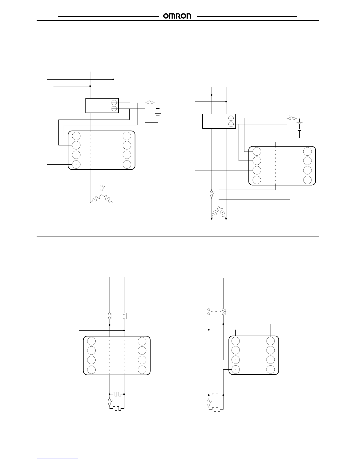
External Connections
K2CU-F A- GS
Single-phase
Heater
Three-phase Heater
G+
G–
S1
S2
b1
CM1
a1
SSR
YBZL
Y/a
Heater
K2CU-F
G+
G–
S1
S2
b1
CM1
a1
YBZL
SSR
Temperature
sensor
Y/a
Heater
K2CU-F
Temperature
controller
Temperature
controller
Power
source
Power
source
Control
voltage
Control
voltage
Temperature
sensor
Page 11

K2CU
K2CU
11
K2CU-F
Single-phase
Heater
Three-phase Heater
S1
S2
YBZL
CM1
a1
Y/a
Heater
K2CU-F
Temperature
controller
Power
source
S1
S2
YBZL
b1
CM1
al
Y/a
Heater
K2CU-F
Temperature
controller
Power
source
Control
contact
Control
contact
Contactor
Contactor
Temperature
sensor
Temperature
sensor
Three-phase, V-connected Heater
W
ith External Current T
ransformer
S1
S2
b1
CM1
al
Heater
K2CU-F
S1
S2
b1
CM1
al
Heater
K2CU-F10A-j
Power
source
CT
jA/SA
CT
jA/SA
Note:
Pass two out of the three line conductors
through the current transformers of the
heater burnout detector twice as shown.
Page 12

K2CU
K2CU
12
K2CU-P Small-capacity, Plug-in Models
Small-capacity
Heater
W
ith External Current T
ransformer
1
2
YBZL
7
8
6
5
4
3
Temperature
sensor
Y/a
Heater
K2CU-P
Temperature
controller
Power
source
Control
contact
7
8
1
2
YBZL
6
5
4
3
Temperature
sensor
Y/a
Heater
K2CU-P
Power
source
CT
jA/5 A
Temperature
controller
Control
contact
Contactor
Note: 1. The
dotted lines which pass through the heater burnout detector indicate the line conductor
passing
through the round “window” of the window-type Current T
ransformer.
2. Y:
External relay for self-holding circuit
BZ:
Alarm buzzer
L:
Alarm indicator
3. To
use an 100 (1
10) V
AC control power supply with K2CU-P
, connect
it to terminal 7 instead
of
6.
Precautions
K2CU-F A- GS
Use
the K2CU-F
jjA-j
GS (with
gate input terminals) in combina
-
tion with a temperature controller that has PID
with feed-forward cir
cuitry to control the heater temperature, in which case, the heater
element(s)
must be turned ON or OFF for 0.1 s or longer
.
K2CU-F
When
a single-phase heater is used, pass the two lines through the
openings of the heater burnout detector
. When a three-phase heat
er is used, pass two (phases) of the three lines through the
open
ings.
In either case, if only one line passes through, an alarm signal
will
always be produced.
With single-phase
power supply
With three-phase
power supply
Heater
Heater
Pass the lines through the
openings only once. If they are passed
more
than once, the actual operating current will be less than the set
current.
The lines can be passed in either direction.
To
use the heater burnout detector at a current less than the current
range
that can be set, the lines must be passed more than once. De
-
termine
the number of
times the lines should be passed by the fol
-
lowing
equation:
(Operating current) x n = Current setting range
where,
n: number of times the lines loop through the window
All
K2CU-F models incorporate a voltage fluctuation compensation
function.
K2CU-P
The
K2CU-P can be used only in single-phase circuits.
Do
not pull out the K2CU-P from the socket when the K2CU-P is en
ergized. Especially when using it in combination with a Current
Transformer commercially available, this practice causes the secondary
circuit of the transformer to open, which is very
dangerous.
Page 13

K2CU
K2CU
13
General
Refer to “
External Connections
” before using the K2CU with exter
-
nal CTs.
When a temperature controller is used in combination with the
K2CU (except for the K2CU-FjjA-jGS), the heater element(s)
must
be turned ON or OFF for 1
s or longer (although the heater ele
-
ment(s)
can be
turned ON for 0.5 s according to the specifications).
The
K2CU
cannot be used with a phase-control circuit, inverter cir
-
cuit,
frequency-count circuit, cycle-control unit, or a motor load.
Mounting
Securely mount the K2CU as horizontally as possible although
there
is no particular limitation of mounting directions.
Connection
Solderless-type terminal must be connected to the terminals securely.
Wire
the terminals correctly by referring to the external connections.
The
terminals have no polarity
. Be sure to connect 100 (or 1
10) V to
the
100-V (or 1
10-V) terminals and 200 (or 220) V to the 200-V
(or
220-V)
terminals of the K2CU-P or the K2CU-P may malfunction.
The control power source for the K2CU (except for the
K2CU-FjjA-jGS)
must
be supplied from the load side via a con
-
tactor.
Be
sure
to impose a voltage between the 0-V terminal and 100-V (or
110-V)
terminal or the 0-V terminal and 200-V (or 220-V) terminal of
the K2CU-P
, otherwise the K2CU-P will not operate.
Operating Current Setting when Several Heaters are Used
The
following
table shows relative values of changes in the current
when
any one of several heaters
connected in parallel has burned
out.
The current value under normal condition is 1. Use this table as
a
guideline in determining the operating current.
Connection
n = 1 n = 2 n = 3 n = 4 n = 5
I
No.
of heater = n
0 0.5 0.67 0.75 0.8
Current
in burned-out phase
0 0.6 0.75 0.82 0.86
I
No.
of heater
per phase = n
Current
in other phases
0.87 0.92 0.95 0.96 0.97
Current in burned-out phase
0.58 0.77 0.84 0.88 0.91
I
No.
of heater
per phase = n
Current
in other phases
1 1 1 1 1
Note: 1.
This table shows the respective change rates in current when any one of several heaters connected in parallel has burned out.
2.
The current value under the normal condition is 1.
3. The
values in this table are logical values. Actually
, these values may vary slightly because of
influence of unbalanced loads (heat
-
ers).
It is therefore recommended to test the actual current values and the load condition before determining the operating current,
especially
when the current under the normal condition and that under an abnormal condition do not significantly dif
fer.
Page 14

K2CU
K2CU
14
OMRON Corporation
Measuring & Supervisory Controls Division
29th Fl., Crystal T
ower Bldg.
1–2–27, Shiromi, Chuo-ku,
Osaka 540 Japan
Phone: 06-949-6014 Fax: 06-949-6028
ALL DIMENSIONS SHOWN ARE IN MILLIMETERS.
To
convert millimeters into inches, multiply by 0.03937. T
o convert grams into ounces, multiply by 0.03527.
Cat. No. N39–E1–2 In the interest of product improvement, specifications are subject to change without notice.
Printed
in Japan
0393–1M (0393)
 Loading...