

Page 1

i4L
Robots
User's Manual
i4-350L
i4-450L
i4-550L
I658-E-03
Page 2

NOTE
All rights reserved. No part of this publication may be reproduced, stored in a retrieval system, or
transmitted, in any form, or by any means, mechanical, electronic, photocopying, recording, or other-
wise, without the prior written permission of OMRON.
No patent liability is assumed with respect to the use of the information contained herein. Moreover,
because OMRON is constantly striving to improve its high-quality products, the information contained
in this manual is subject to change without notice. Every precaution has been taken in the preparation
of this manual. Nevertheless, OMRON assumes no responsibility for errors or omissions. Neither is
any liability assumed for damages resulting from the use of the information contained in this publica-
tion.
Trademarks
Company names and product names in this document are the trademarks or registered trademarks of
their respective companies.
Copyrights
Microsoft product screen shots reprinted with permission from Microsoft Corporation.
Page 3

Introduction
Thank you for purchasing the i4L robot.
This manual is OMRON's original instructions describing the setup, operations, and user maintenance
of the i4L robot (herein also referred to as robot).
Please read this manual and make sure you understand the functionality and performance of the robot
before attempting to use it.
Keep this manual in a safe place where it will be available for reference during operation.
Intended Audience
This manual is intended for the following personnel, who must also have knowledge of factory automa-
tion (FA) systems and robotic control methods.
• Personnel in charge of introducing FA systems.
• Personnel in charge of designing FA systems.
• Personnel in charge of installing and maintaining FA systems.
• Personnel in charge of managing FA systems and facilities.
Introduction
Applicable Products
This manual provides information for the following robot models.
When information varies between different robot models, details are provided. When information is
common to all robot models, an illustration of a single robot model is typically shown.
i4L Robot i4-350L
Additional Information
Refer to 1-4 Robot Configurations on page 1-12 for more information.
Product Models
i4-450L
i4-550L
i4-550L (350 mm Z)
i4L Robots User's Manual (I658)
1
Page 4

A
B
C
E
F
B
C
H
5 Installation
5 - 3
NY-series User's Manual (W555)
5-1 Unpack
5
5-1-1 Unpack Procedure
G
5-1
Unpack
This section provides details on how to unpack the Industrial Panel PC.
5-1-1
Unpack Procedure
1 Check the package for damage.
If there is any visible damage:
• Take photos of the package and save them.
• Inform your supplier immediately.
2 Open the package.
Ensure not to damage the contents.
3 Ensure that all items are present.
Additional Information
Refer to 5-1-2 Items Supplied with the Product
for the items supplied.
Manual Information
Manual Information
Page Structure
The following page structure is used in this manual.
Note: This illustration is provided as a sample. It will not literally appear in this manual.
Item Explanation Item Explanation
A Level 1 heading E Special Information
B Level 2 heading F Manual name
C Level 3 heading G Page tab with the number of the main section
D Step in a procedure H Page number
2
i4L Robots User's Manual (I658)
Page 5

Special Information
Special information in this manual is classified as follows:
Precautions for Safe Use
Precautions on what to do and what not to do to ensure safe usage of the product.
Precautions for Correct Use
Precautions on what to do and what not to do to ensure proper operation and performance.
Additional Information
Additional information to read as required.
This information is provided to increase understanding or make operation easier.
Version Information
Manual Information
Information on differences in specifications and functionality between different versions.
i4L Robots User's Manual (I658)
3
Page 6

Manual Information
4
i4L Robots User's Manual (I658)
Page 7

Sections in this Manual
Maintenance
Operation
Troubleshooting
Installation
Specifications
Overview
1
2
3
4
5
6
1
2
3
4
6
5
1
A
A
Appendices
Sections in this Manual
i4L Robots User's Manual (I658)
5
Page 8

CONTENTS
CONTENTS
Introduction .............................................................................................................. 1
Intended Audience...........................................................................................................................................1
Applicable Products ......................................................................................................................................... 1
Manual Information.................................................................................................. 2
Page Structure.................................................................................................................................................2
Special Information .......................................................................................................................................... 3
Sections in this Manual ........................................................................................... 5
Terms and Conditions Agreement........................................................................ 10
Warranty and Limitations of Liability .............................................................................................................. 10
Application Considerations ............................................................................................................................11
Disclaimers ....................................................................................................................................................11
Safety Precautions................................................................................................. 13
Definition of Precautionary Information.......................................................................................................... 13
Symbols ......................................................................................................................................................... 13
Dangers .........................................................................................................................................................14
Warnings........................................................................................................................................................ 15
Cautions......................................................................................................................................................... 17
Precautions for Safe Use ...................................................................................... 18
Precautions for Correct Use ................................................................................. 20
Regulations and Standards .................................................................................. 22
Conformance to EU Directives ......................................................................................................................22
Conformance to KC Certification ...................................................................................................................22
Software Licenses and Copyrights ................................................................................................................23
Related Manuals..................................................................................................... 24
Related Product Manuals ..............................................................................................................................24
Glossary.................................................................................................................. 25
Revision History..................................................................................................... 26
Section 1 Overview
1-1 Intended Use ..........................................................................................................................1-2
1-2 Robot Features.......................................................................................................................1-3
1-2-1 Basic Robot Components ...........................................................................................................1-3
1-2-2 Front Panel..................................................................................................................................1-5
1-2-3 Connectors..................................................................................................................................1-7
1-3 Information Labels...............................................................................................................1-10
1-3-1 Robot Label...............................................................................................................................1-10
1-3-2 Controller Label......................................................................................................................... 1-11
1-4 Robot Configurations .......................................................................................................... 1-12
1-4-1 i4-350L ......................................................................................................................................1-12
1-4-2 i4-450L ......................................................................................................................................1-12
1-4-3 i4-550L ......................................................................................................................................1-12
6
i4L Robots User's Manual (I658)
Page 9

1-4-4 i4-550L (350 mm Z)...................................................................................................................1-13
1-4-5 Mounting and Cabling Options..................................................................................................1-13
1-5 Model Numbers ....................................................................................................................1-14
1-5-1 Robot Model Numbers ..............................................................................................................1-14
1-5-2 Controller Model Numbers ........................................................................................................1-14
1-6 Optional Hardware ...............................................................................................................1-15
1-6-1 IO Blox ......................................................................................................................................1-15
1-6-2 T20 Pendant..............................................................................................................................1-15
1-6-3 IPC Application Controller.........................................................................................................1-16
1-6-4 XIO Termination Block...............................................................................................................1-16
1-6-5 Optional Cables.........................................................................................................................1-17
Section 2 Specifications
2-1 Physical Specifications .........................................................................................................2-2
2-1-1 Robot Overall Dimensions ..........................................................................................................2-2
2-1-2 Mounting Flange Dimensions......................................................................................................2-4
2-1-3 Tool Flange Dimensions..............................................................................................................2-5
2-1-4 Front Panel Dimensions..............................................................................................................2-5
2-1-5 Robot Work Envelope Dimensions..............................................................................................2-6
2-1-6 Robot Weights.............................................................................................................................2-7
2-2 Performance Specifications..................................................................................................2-8
2-2-1 General Performance Information...............................................................................................2-8
2-2-2 Stopping Distances and Times....................................................................................................2-8
2-3 Electrical Specifications......................................................................................................2-12
2-3-1 Power Supply Specifications.....................................................................................................2-12
2-3-2 XIO and TIO Connector I/O Specifications ...............................................................................2-12
2-4 Environmental Specifications.............................................................................................2-14
2-5 Other Specifications ............................................................................................................2-15
2-5-1 Connector and Port Specifications............................................................................................2-15
2-5-2 Mounting Hardware and Torques..............................................................................................2-15
CONTENTS
Section 3 Installation
3-1 Robot Installation Procedure................................................................................................3-2
3-2 Mounting the Robot ............................................................................................................... 3-3
3-2-1 Robot Mounting Surface .............................................................................................................3-3
3-2-2 Mounting Procedure....................................................................................................................3-3
3-3 Installing End-of-Arm Tooling............................................................................................... 3-5
3-4 Installing Optional Equipment .............................................................................................. 3-6
3-4-1 Mounting External Equipment to the Robot ................................................................................3-6
3-5 Adjustable Hardstops............................................................................................................3-7
3-5-1 Joint 1 Adjustable Hardstops ......................................................................................................3-8
3-5-2 Joint 2 Adjustable Hardstops ......................................................................................................3-8
3-5-3 Joint 3 Adjustable Hardstop ........................................................................................................3-8
3-6 System Cable Installation ...................................................................................................3-10
3-6-1 System Cable Overview............................................................................................................3-10
3-6-2 System Cable Installation Procedure........................................................................................3-12
3-7 Connecting Digital I/O .........................................................................................................3-13
3-7-1 XIO Connector Signals and Wiring ...........................................................................................3-13
3-7-2 TIO Connector Signals and Wiring............................................................................................3-17
3-7-3 IO Blox Connections .................................................................................................................3-19
3-8 Installing Safety Equipment................................................................................................3-20
3-8-1 Installing the Front Panel ..........................................................................................................3-20
i4L Robots User's Manual (I658)
7
Page 10

CONTENTS
3-8-2 Safety Circuits...........................................................................................................................3-21
3-9 Supplying Power and Ground ............................................................................................3-28
3-9-1 Grounding the System ..............................................................................................................3-28
3-9-2 24 VDC Connections.................................................................................................................3-29
3-9-3 48 VDC Connections.................................................................................................................3-29
3-10 Verifying Installation............................................................................................................3-31
3-10-1 Mechanical Checks ...................................................................................................................3-31
3-10-2 System Cable Checks...............................................................................................................3-31
3-10-3 Safety Equipment Checks.........................................................................................................3-31
3-10-4 Switch Position Checks.............................................................................................................3-33
Section 4 Operation
4-1 Payload and Acceleration Considerations .......................................................................... 4-2
4-2 Robot Control Modes ............................................................................................................4-3
4-2-1 Manual Mode ..............................................................................................................................4-3
4-2-2 Automatic Mode ..........................................................................................................................4-3
4-3 Enabling and Disabling the Robot .......................................................................................4-5
4-3-1 Enabling Robot High Power........................................................................................................4-5
4-3-2 Disabling High Power..................................................................................................................4-6
4-4 LED Indicator..........................................................................................................................4-7
4-5 Brake Operation .....................................................................................................................4-8
4-5-1 Built-in Brake Release Button .....................................................................................................4-8
4-6 Connecting to the Robot ..................................................................................................... 4-10
4-6-1 Initial Connection Procedure.....................................................................................................4-10
4-7 Manually Jogging the Robot............................................................................................... 4-11
Section 5 Troubleshooting
5-1 Fault Detection .......................................................................................................................5-2
5-2 Emergency Stop Troubleshooting .......................................................................................5-3
5-3 Error Messages ......................................................................................................................5-4
Section 6 Maintenance
6-1 Field-replaceable Items .........................................................................................................6-2
6-2 Periodic Maintenance ............................................................................................................6-3
6-2-1 Periodic Maintenance Overview..................................................................................................6-3
6-2-2 Checking Safety Functions .........................................................................................................6-3
6-2-3 Checking Fastener Torques ........................................................................................................6-4
6-2-4 Checking Safety and Warning Labels .........................................................................................6-4
6-2-5 Checking for Oil Leaks................................................................................................................6-5
6-2-6 Lubricating Joint 3.......................................................................................................................6-6
6-2-7 Replacing Encoder Backup Batteries..........................................................................................6-7
6-2-8 Cleaning the Robot .....................................................................................................................6-8
6-3 Non-periodic Maintenance .................................................................................................... 6-9
6-3-1 Replacing the Tool Flange...........................................................................................................6-9
Appendices
A-1 Unpacking and Inspecting the Robot ................................................................................. A-2
8
i4L Robots User's Manual (I658)
Page 11

Index
CONTENTS
A-1-1 Before Unpacking the Robot ...................................................................................................... A-2
A-1-2 Unpacking the Robot.................................................................................................................. A-2
A-2 Repacking the Robot for Transport..................................................................................... A-4
A-3 Transportation and Storage Considerations...................................................................... A-5
A-4 I/O Signal Numbering ........................................................................................................... A-6
A-4-1 Input Signal Numbering.............................................................................................................. A-6
A-4-2 Output Signal Numbering........................................................................................................... A-6
A-5 Cable Pinouts ........................................................................................................................ A-7
A-5-1 XSYSTEM Cable Pinouts........................................................................................................... A-7
A-5-2 XBELTIO Adapter Cable Pinouts ............................................................................................... A-8
A-5-3 Belt Encoder Y-adapter Cable Pinouts....................................................................................... A-9
A-6 Parts List.............................................................................................................................. A-11
i4L Robots User's Manual (I658)
9
Page 12

Terms and Conditions Agreement
Terms and Conditions Agreement
Warranty and Limitations of Liability
Warranty
Exclusive Warranty
Omron’s exclusive warranty is that the Products will be free from defects in materials and work-
manship for a period of twelve months from the date of sale by Omron (or such other period ex-
pressed in writing by Omron). Omron disclaims all other warranties, expressed or implied.
Limitations
OMRON MAKES NO WARRANTY OR REPRESENTATION, EXPRESS OR IMPLIED, ABOUT
NON-INFRINGEMENT, MERCHANTABILITY OR FITNESS FOR A PARTICULAR PURPOSE OF
THE PRODUCTS. BUYER ACKNOWLEDGES THAT IT ALONE HAS DETERMINED THAT THE
PRODUCTS WILL SUITABLY MEET THE REQUIREMENTS OF THEIR INTENDED USE.
Omron further disclaims all warranties and responsibility of any type for claims or expenses based
on infringement by the Products or otherwise of any intellectual property right.
Buyer Remedy
Omron’s sole obligation hereunder shall be, at Omron’s election, to (i) replace (in the form originally
shipped with Buyer responsible for labor charges for removal or replacement thereof) the non-com-
plying Product, (ii) repair the non-complying Product, or (iii) repay or credit Buyer an amount equal
to the purchase price of the non-complying Product; provided that in no event shall Omron be re-
sponsible for warranty, repair, indemnity or any other claims or expenses regarding the Products
unless Omron’s analysis confirms that the Products were properly handled, stored, installed and
maintained and not subject to contamination, abuse, misuse or inappropriate modification. Return
of any Products by Buyer must be approved in writing by Omron before shipment. Omron Compa-
nies shall not be liable for the suitability or unsuitability or the results from the use of Products in
combination with any electrical or electronic components, circuits, system assemblies or any other
materials or substances or environments. Any advice, recommendations or information given orally
or in writing, are not to be construed as an amendment or addition to the above warranty.
See http://www.omron.com/global/ or contact your Omron representative for published information.
Limitations of Liability
OMRON COMPANIES SHALL NOT BE LIABLE FOR SPECIAL, INDIRECT, INCIDENTAL, OR CON-
SEQUENTIAL DAMAGES, LOSS OF PROFITS OR PRODUCTION OR COMMERCIAL LOSS IN ANY
WAY CONNECTED WITH THE PRODUCTS, WHETHER SUCH CLAIM IS BASED IN CONTRACT,
WARRANTY, NEGLIGENCE OR STRICT LIABILITY. Further, in no event shall liability of Omron Com-
panies exceed the individual price of the Product on which liability is asserted.
10
i4L Robots User's Manual (I658)
Page 13

Application Considerations
Suitability for Use
Omron Companies shall not be responsible for conformity with any standards, codes or regulations
which apply to the combination of the Product in the Buyer’s application or use of the Product. At Buy-
er’s request, Omron will provide applicable third party certification documents identifying ratings and
limitations of use which apply to the Product. This information by itself is not sufficient for a complete
determination of the suitability of the Product in combination with the end product, machine, system, or
other application or use. Buyer shall be solely responsible for determining appropriateness of the par-
ticular Product with respect to Buyer’s application, product or system. Buyer shall take application re-
sponsibility in all cases.
NEVER USE THE PRODUCT FOR AN APPLICATION INVOLVING SERIOUS RISK TO LIFE OR
PROPERTY WITHOUT ENSURING THAT THE SYSTEM AS A WHOLE HAS BEEN DESIGNED TO
ADDRESS THE RISKS, AND THAT THE OMRON PRODUCT(S) IS PROPERLY RATED AND IN-
STALLED FOR THE INTENDED USE WITHIN THE OVERALL EQUIPMENT OR SYSTEM.
Terms and Conditions Agreement
Programmable Products
• Omron Companies shall not be responsible for the user’s programming of a programmable Product,
or any consequence thereof.
• Omron Companies shall not be responsible for the operation of the user accessible operating sys-
tem (e.g. Windows, Linux), or any consequence thereof.
Disclaimers
Performance Data
Data presented in Omron Company websites, catalogs and other materials is provided as a guide for
the user in determining suitability and does not constitute a warranty. It may represent the result of
Omron’s test conditions, and the user must correlate it to actual application requirements. Actual per-
formance is subject to the Omron’s Warranty and Limitations of Liability.
Change in Specifications
Product specifications and accessories may be changed at any time based on improvements and oth-
er reasons. It is our practice to change part numbers when published ratings or features are changed,
or when significant construction changes are made. However, some specifications of the Product may
be changed without any notice. When in doubt, special part numbers may be assigned to fix or estab-
lish key specifications for your application. Please consult with your Omron’s representative at any
time to confirm actual specifications of purchased Product.
i4L Robots User's Manual (I658)
11
Page 14

Terms and Conditions Agreement
Errors and Omissions
Information presented by Omron Companies has been checked and is believed to be accurate; how-
ever, no responsibility is assumed for clerical, typographical or proofreading errors or omissions.
12
i4L Robots User's Manual (I658)
Page 15

Safety Precautions
Definition of Precautionary Information
The following notation is used in this manual to provide precautions required to ensure safe usage of
the i4L robot. The safety precautions that are provided are extremely important to safety.
Always read and heed the information provided in all safety precautions.
The following notation is used.
Identifies an imminently hazardous situation which, if not avoid-
DANGER
WARNING
ed, is likely to result in serious injury, and might result in fatality
or severe property damage.
Indicates a potentially hazardous situation which, if not avoid-
ed, could result in death or serious injury. Additionally, there
may be severe property damage.
Safety Precautions
Symbols
Indicates a potentially hazardous situation which, if not avoid-
CAUTION
The circle and slash symbol indicates operations that you must not do. The specific operation is shown in the circle and explained in text.
This example indicates prohibiting disassembly.
The triangle symbol indicates precautions (including warnings).
The specific operation is shown in the triangle and explained in text.
This example indicates a precaution for electric shock.
The triangle symbol indicates precautions (including warnings).
The specific operation is shown in the triangle and explained in text.
This example indicates a general precaution.
The filled circle symbol indicates operations that you must do.
The specific operation is shown in the circle and explained in text.
This example shows a general precaution for something that you must do.
The triangle symbol indicates precautions (including warnings).
The specific operation is shown in the triangle and explained in text.
This example indicates a precaution for high temperatures.
ed, may result in minor or moderate injury, or property damage.
i4L Robots User's Manual (I658)
13
Page 16

Safety Precautions
Dangers
General
An i4L robot can cause serious injury or death, or damage to itself and other equipment,
if the following safety precautions are not observed:
• All personnel who install, operate, teach, program, or maintain the system must read
this guide, read the Robot Safety Guide, and complete a training course for their responsibilities in regard to the robot.
• All personnel who design the robot system must read this guide, read the Robot Safe-
ty Guide, and must comply with all local and national safety regulations for the location
in which the robot is installed.
• The robot system must not be used for purposes other than described in 1-1 Intended
Use on page 1-2. Contact your local Omron support if you are not sure of the suitability for your application.
• The user is responsible for providing safety barriers around the robot to prevent any-
one from accidentally coming into contact with the robot when it is in motion.
• Power to the robot and its power supply must be locked out and tagged out before any
maintenance is performed.
• When the robot or robotic equipment is not investigated in conjunction with a system
work cell, the instructions shall call attention to the following: the interlocked portion of
barrier shall be installed, applied, and maintained so that it has the capability of being
easily unlocked from the inside of the safeguarded space, with or without power available, when the possibility of full body access exists.
i4L robots are not collaborative robots. They require a dedicated work area that will prevent personnel from coming into contact with them during operation.
The normal and intended use of these robots does not create hazards.
These robots have been designed and constructed in accordance with the relevant requirements of IEC 60204-1.
These robots are intended for use in parts assembly and material handling for payloads
up to 5.0 kg.
Refer to the Robot Safety Guide (Cat. No. I590) for details on the intended use of our
robots.
These robots are intended for industrial use only.
Perform a risk assessment before using.
These robots are not intended for:
• Use in the presence of ionizing or non-ionizing radiation.
• Use in potentially explosive atmospheres.
• Use in medical or life saving applications.
• Use in a residential setting.
DANGER
14
Installation
i4L Robots User's Manual (I658)
Page 17

The robot system must be installed with user-supplied interlock barriers. The interlocked
barriers must open the E-Stop circuit in the event of personnel attempting to enter the
work cell when High Power is enabled. Failure to install suitable guarding or interlocks
could result in injury or death. We strictly prohibit installation, commissioning, or operation of any robot without adequate safeguards. These must be compliant with applicable
local and national standards.
The placement of safety controls shall avoid requiring a person to enter a hazardous
area to actuate them.
Controls shall be located outside of the safeguarded space, except for certain controls
such as emergency stops or a teach pendant, where based on a risk assessment they
may be located within the safeguarded space.
After installing the robot, you must test it before you use it for the first time. Failure to do
this could cause death, serious injury, or equipment damage.
Failure to ground robot-mounted equipment or tooling that uses hazardous voltages
could lead to injury or fatality of a person touching the end-effector during an electrical
fault.
Any High Power push-buttons must be installed outside of the robot's workspace.
Safety Precautions
Warnings
General
The instructions for operation, installation, and maintenance given in this document must
be strictly observed.
If air pressure is present, disconnect it from the robot when servicing end-of-arm tooling
or other pneumatic components to prevent unsecured pneumatic air lines from accidentally injuring personnel.
Do not move the robot links if the robot is not secured. Failure to comply could result in
the robot falling and causing either personnel injury or property damage.
Installation
WARNING
Ensure that installation and post-installation checks of the product are performed by personnel in charge who possess a thorough understanding of the machinery to be installed.
Ensure compliance with all local and national safety and electrical codes for the installation and operation of the robot system.
i4L Robots User's Manual (I658)
15
Page 18

Safety Precautions
Provide appropriately-sized Branch Circuit Protection and Lockout / Tagout Capability in
accordance with the National Electrical Code and any local codes.
Always use proper lifting technique when lifting the robot. Failure to comply could result
in the robot falling and causing either personnel injury or equipment damage.
If you supply your own Front Panel, its design must comply with the requirements of IEC
60204-1 and ISO 13849. The E-Stop's push button must comply with ISO 13850 (Clause
5.5.2).
Disabling the High Power button violates IEC 60204-1. Do not alter its functionality.
If a robot is mounted to a surface with inadequate stiffness, damage to the z-axis quill or
other mechanical components can result from excessive oscillation during operation.
The robot's center of mass can cause the robot to fall over if the robot is not properly
secured with the mounting bolts.
The robot must be installed to avoid interference with buildings, structures, utilities, other
machines and equipment that may create trapping or pinch points. It must be installed in
accordance with Standard for Robots and Robotic Devices – Safety Requirements for Industrial Robots – Part 2: Robot Systems and Integration, ISO 10218-2.
Ensure that interconnecting cables or pneumatic lines are routed away from the robot
workspace.
To reduce the risk of fire or electric shock, install the robot in a controlled environment
relatively free of contaminants.
Operation
Before starting the operation of equipment, always confirm that the safety equipment of
the robot works properly. If a malfunction of the safety equipment is detected, follow the
troubleshooting procedure.
Use the total weight of the end-of-arm tooling and the payload to stay within the payload
rating of the robot. Ensure that the system never exceeds that maximum payload.
Perform a full risk assessment which includes the end-of-arm tooling and any payload to
prevent crushing, shearing, payload ejection, entanglement, stabbing or puncture hazard.
16
Releasing a brake may cause the quill, tool flange, end-of-arm tooling, and payload to
drop. To prevent possible injury to personnel or damage to the equipment, make sure
that the equipment is supported when releasing the brake and verify that the end-of-arm
tooling and payload are clear of all obstructions.
All signals that pass-through the USER connectors are not associated with any robot
controls, emergency stop circuits, or robot power. Implement appropriate safety measures to ensure that these signals are not active during emergency stop conditions or
while the robot is powered OFF.
i4L Robots User's Manual (I658)
Page 19

In Automatic mode, the robot can move unexpectedly. Ensure all personnel remain clear
of the cell when Automatic mode is enabled.
If an operator is going to be in the work cell with the switch in Manual mode, the operator
must carry an enabling device such as the T20 pendant.
Whenever possible, perform Manual mode operations with all personnel outside the
workspace.
The stopping time and distance, or angle, of a robot joint from initiation of a stop signal is
not negligible and must be taken into account when designing and applying safeguarding
devices.
Never connect or disconnect system cables while power is applied to the robot. Failure
to comply may cause unexpected behavior and can result in personnel injury and equipment damage.
Never run a robot system with all jumpers installed. This would leave the system with no
E-Stops.
Safety Precautions
Do not use the robot in hazardous environments (explosive gas, and oil mist).
The robot shall be operated within its specified temperature range to ensure proper operation.
The robot's physical hardstop devices are not intended to withstand repeated use and if
this occurs, the hardstop may become damaged. Implement proper programming and
configuration of joint range limits to prevent hardstop impacts.
Maintenance
Do not use organic solvents to clean any part of the robot unless directed in the cleaning
instructions. Organic solvents might damage electronics resulting in an unsafe operating
state that could cause injury or damage to equipment.
Cautions
CAUTION
The design and installation of the complete system must comply with the safety standards and regulations in the country of use. The integrators of the robot should understand the safety laws and regulations in their countries and prevent major hazards from
occurring in the complete system.
i4L Robots User's Manual (I658)
17
Page 20

Precautions for Safe Use
Precautions for Safe Use
• The Joint 3 quill and the tool flange are not grounded to protective earth. If hazardous voltages are
present at any user-supplied robot-mounted equipment or tooling, you must install a ground connec-
tion from that equipment or tooling to the ground point on the robot base.
• This equipment must be shipped and stored in a temperature-controlled environment, within the
range –25 to +55°C. The recommended humidity range is 5 to 90%, non-condensing. It should be
shipped and stored in the supplied packaging, which is designed to prevent damage from normal
shock and vibration.
• Output 8 can be assigned to indicate the robot's High Power state. When High Power is enabled,
this output will turn ON. When High Power is not enabled, this output will be OFF. This is not a safe-
ty-rated means of indicating a High Power state and should only be used for monitoring the robot
status. Use the ACE software to make this configuration if needed.
• Do not apply 48 VDC power until all installation steps are complete and verified and all safety meas-
ures are in place.
• High power cannot be enabled unless all safety circuits are satisfied.
• The LED indicator does not reflect the robot's High Power status. To see the robot's High Power sta-
tus, use the Front Panel indicator or a user-supplied indicator connected to the XFP connector.
• The braking mechanism operates passively. If 24 VDC Control Power is removed from the system,
the brake mechanism will automatically activate. 24 VDC Control Power must be supplied to release
the brake. To prevent possible damage to the equipment, remove any payload from the end-of-arm
tooling, make sure that Joint 3 is supported while releasing the brake, and verify that the end-of-arm
tooling or other installed equipment is clear of all obstructions.
• The High Power indicator must be operational to satisfy safety requirements.
• You can contribute to resource conservation and protecting the environment by the proper disposal
of Waste Electronics and Electrical Equipment (WEEE). All electrical and electronic products should
be disposed of separately from the municipal waste system according to local ordinances using des-
ignated collection facilities.
18
• The product contains lithium batteries with a perchlorate content of 6ppb or higher. When exporting
an end product containing the product to or shipping through California, USA, label all packing and
shipping containers appropriately. Special handling may apply. Refer to https://dtsc.ca.gov for more
information.
• Dispose of any battery that has been dropped or otherwise subjected to excessive shock. Batteries
that have been subjected to shock may leak if they are used.
• Batteries may leak, rupture, heat, or ignite. Never short-circuit, charge, disassemble, heat, or incin-
erate a battery or subject it to strong shock.
• Any person who programs, teaches, operates, maintains, or repairs robots or robot systems shall be
trained and can demonstrate competence to safely perform the assigned task.
• Any person who programs, teaches, operates, maintains, or repairs robots or robot systems shall be
trained on responding to emergency or abnormal situations.
• Do not connect user-supplied Manual / Automatic contacts or other control signals in parallel with
the Front Panel switch contact. This would violate the Single Point of Control principle and might al-
low Automatic mode to be selected while an operator is in the cell.
i4L Robots User's Manual (I658)
Page 21

Precautions for Safe Use
• Acoustic emission from these robots may be up to 70 dB (A) at 1 m distance under worst-case con-
ditions. Typical values will be lower, depending on payload, speed, acceleration, and mounting. Ap-
propriate safety measures should be taken, such as ear protection and display of a warning sign.
• Any moving robot requires some distance to stop. This requires more distance at high operating
speeds or heavier payloads. When stopping a robot, make sure that there is no interference with
other equipment.
• Do not expose the shipping container to excessive shock and vibration. This could damage the ro-
bot.
• Using improper lubrication products on the robot may damage it.
• After an operator places the robot in Manual mode using the Front Panel key switch, they should
remove the key for safety purposes.
• If the supplied Front Panel is not used, a High Power indicator light must be present in the system.
This indicator light must be amber in color. It must be either mounted to the robot or integrated into
the work cell where it is visible from all approaches or entry points.
• If a supplementary audible means of robot operation is provided, it shall exceed the ambient noise
at the end-use application.
• You can burn yourself. Do not touch the robot after it has been running at high ambient tempera-
tures or at fast cycle times (over 60 cycles per minute). The robot surface temperature can exceed
85° C.
• During manual operation, ensure all persons are a safe distance away from the robot work enve-
lope.
• The robot can be lifted by hand. Only use the base and inner link when lifting the robot. Never ma-
neuver the robot using the quill or flyover assemblies.
• To stop the robot in an emergency, press any E-stop button and then follow the internal procedures
of your company or organization defined for an emergency situation.
• If a fire occurs on the robot, use a CO2 type fire extinguisher.
• In case of entrapment of a person by the robot or any other emergency or abnormal situation, you
can manually move the inner and outer links to a safe position while 48 VDC High Power is disa-
bled. A brake device prevents Joints 3 and 4 from moving when High Power is disabled and can
only be released while 24 VDC Control Power is present.
• Prior to placing the robot in Automatic Mode, all safeguards must be returned to their safe state.
i4L Robots User's Manual (I658)
19
Page 22

Precautions for Correct Use
Precautions for Correct Use
• Robot motion is not possible until High Power is supplied and has been enabled. Refer to 4-3 Ena-
bling and Disabling the Robot on page 4-5 for more information.
• Control power must be present before High Power can be enabled.
• The T20 pendant can only control the robot it is directly connected to.
• Either a Front Panel or equivalent circuits are required to enable High Power to the robot. Refer to
XFP Wiring Diagram on page 3-24 for more information.
• If the Front Panel High Power ON / OFF indicator fails, you might incorrectly assume that High Pow-
er is OFF, and the robot is safe. To prevent this, a failed indicator causes an error (-924) *Front pan-
el HIGH POWER lamp failure* and locks out the High Power enabling until you replace the indicator.
Refer to the eV+ Language Reference Guide (Cat. No. I605) for more information about error han-
dling. Refer to High Power Indicator Check Procedure on page 3-32 for information about High Pow-
er indicator operation verification.
• It is recommended to use a properly secured, 18 mm (minimum) thick steel plate with a maximum
surface roughness of 25 μm as a robot mounting surface.
• The mounting surface should be clean and prepared according to the information provided in
3-2-1 Robot Mounting Surface on page 3-3 before attempting to mount the robot.
• Do not over-tighten the tool flange setscrew. This will cause off-center alignment of the tool flange
on the quill.
• Always reduce joint motion limits with software configuration settings when hardstops are used to
restrict range of motion. Refer to the Automation Control Environment (ACE) Version 4 User's
Manual (Cat. No. I633) for more information.
• Never loosen or remove the quill clamp collar while the z-axis brake is released.
• If Teach Pendant cabling is installed, the jumper plug or the Teach Pendant must be connected to
satisfy safety circuits and allow High Power to be enabled.
• Do not disable or bypass the High Power button. This will violate IEC 60204-1.
• Operating the robot outside of the payload and speed constraints described in this document can
damage or reduce the service life of the z-axis quill.
• If a Front Panel is not present, the High Power indicator and High Power button signals can be ac-
cessed with the XFP system cable connector. Refer to Front Panel Connections on page 3-21 for
more information.
• Attempting to release the brake while High Power is ON will automatically disable High Power. If the
robot is moving, this will cause it to stop abruptly.
• If no controller(s) is detected, check the Ethernet network and cables and ensure that a network
connection is available to the robot and the PC.
• Only replace items on the robot system with the parts supplied by OMRON.
• Only use the recommended grease on the joint 3 quill. Use THK AFF Grease (part number
20950-000). Refer to the provided Safety Data Sheet for proper handling.
• When removing and replacing the tool flange, you must reinstall it in the same position to avoid los-
ing the calibration for the robot.
• Use surge suppression when switching inductive loads such as relays to prevent damage to the out-
put circuits.
• Any externally mounted equipment is considered robot payload. Consideration to the payload at-
tached to the Tool Flange should be made when mounting external equipment to the robot.
20
i4L Robots User's Manual (I658)
Page 23

Precautions for Correct Use
• If the robot has a bottom Primary Interface Panel orientation, do not temporarily set the robot upright
on a flat surface because this can damange the Primary Interface Panel connectors.
• Avoid rotating the quill / Joint 4 when the brake is released. This could result in an out-of-range con-
dition and may prevent program execution.
• All fastener torque values provided must be applied within ±5%.
• Keep a minimum of 300 mm clearance from the Primary Interface Panel to allow for switch and ca-
ble connection access.
i4L Robots User's Manual (I658)
21
Page 24

Regulations and Standards
Regulations and Standards
Conformance to EU Directives
The robot complies with the following EN Directives.
Directives
• 2006/42/EC
Machinery Directive
• 2014/30/EU
EMC Directive
EN Harmonized Standards
The robot system conforms to the following EN standards.
• EN ISO 12100
Safety of Machinery
General Principles for Design
Risk Assessment and Reduction
• EN ISO 13849-1
Safety of Machinery
Safety Related Parts of Control Systems SRP/CS – Part 1
• EN ISO 10218-1
Robots for industrial environments
Safety requirements, Part 1: Robot
• EN 60204-1
Safety of Machinery
Electrical equipment of machines, Part 1 General Requirements
• EN 61000-6-4
EMC, Part 6-4: Emissions Standard for Industrial Environments
• EN 61000-6-2
EMC, Part 6-2: Immunity Emissions Standard for Industrial Environments
Conformance to KC Certification
When you use this product in South Korea, observe the following precautions.
This product meets the electromagnetic compatibility requirements for business use. There is a risk of
radio interference when this product is used in home.
22
i4L Robots User's Manual (I658)
Page 25

Software Licenses and Copyrights
This product incorporates certain third party software. The license and copyright information associat-
ed with this software is available at http://www.fa.omron.co.jp/nj_info_e/.
Regulations and Standards
i4L Robots User's Manual (I658)
23
Page 26

Related Manuals
Related Manuals
Use the following related manuals for reference.
Related Product Manuals
Manual Name Description
eV+ Language User's Guide (Cat. No.
I604)
eV+ Language Reference Guide (Cat. No.
I605)
eV+ Operating System User's Guide (Cat.
No. I606)
eV+ Operating System Reference Guide
(Cat. No. I607)
Robot Safety Guide (Cat. No. I590) Contains safety information for OMRON industrial robots.
Automation Control Environment (ACE)
Version 4 User's Manual (Cat. No. I633)
T20 Pendant User's Manual (Cat. No. I601) Describes the use of the T20 manual control pendant.
Adept XIO Termination Block Installation
Guide (00340-000)
Omron Adept IO Blox User's Guide
(04638-000)
IPC Application Controller User's Manual
(Cat. No. I632)
Provides the concepts and strategies of programming with eV+.
Provides references to eV+ language and functionality.
Describes the eV+ operating system for v2.x.
Provides eV+ operating system keyword descriptions.
Contains information that is necessary to use Automation Control
Environment (ACE) software.
Describes the use of the XIO Termination Block unit.
Describes the use of the IO Blox unit.
Describes the use of the IPC Application Controller.
24
i4L Robots User's Manual (I658)
Page 27

Glossary
Term / Abbreviation Description
Application Controller Industrial PC that provides additional functionality to the robot to execute
Automatic Mode Operating state of the robot during normal conditions. In this mode, pro-
Control Power 24 VDC supply that energizes control and other non-servo motor circuits.
End-of-arm Tooling Any device mounted to the robot's tool flange intended for performing work
Emergency Stop An action or device used to immediately stop the robot. This may be refer-
Flyover The cable assembly that connects the robot base to the outer link.
Hardstop Physical limit that restricts the range of motion for a robot axis.
High Power 48 VDC supply that energizes all internal servo motors to allow robot mo-
Joint Mechanical robot component that connects its moving parts.
LED Indicator Multi-colored light on top of the outer link that provides a visual indication of
Link Mechanical robot component that moves in a radial motion.
Manual Mode Operating state of the robot during commissioning, position teaching, and
SCARA Selective Compliance Assembly Robot Arm
T20 Pendant Optional, handheld device used to manually jog the robot, teach locations,
Quill Mechanical robot component that provides motion in the z-axis and rotary
Work Envelope Working area that is accessible by the robot considering any end-of-arm
Workspace Total area that the robot occupies considering all capable range of motion.
Glossary
PackManager and Robot Vision Manager applications.
gram execution will control the robot up to the maximum allowable speed.
during robot operation.
red to as emergency stop, E-stop, or ESTOP.
tion.
the robot operating state.
other setup operations.
and debug programs without a PC. This is also referred to as a Teach
Pendant or a pendant.
motion for the tool flange. This is a ball-screw mechanism.
tooling and part shapes that are attached.
i4L Robots User's Manual (I658)
25
Page 28

I658-E-03
Cat. No.
Revision code
Revision History
Revision History
A manual revision code appears as a suffix to the catalog number on the front and back covers of the
manual.
Revision code Date Revised content
01 November 2020 Original production
02 December 2020 Minor modifications
03 January 2021 Corrections and revisions
26
i4L Robots User's Manual (I658)
Page 29

Overview
This section provides general information about the robot.
1-1 Intended Use................................................................................................... 1-2
1-2 Robot Features............................................................................................... 1-3
1-3 Information Labels .......................................................................................1-10
1-4 Robot Configurations ..................................................................................1-12
1-5 Model Numbers ............................................................................................1-14
1-6 Optional Hardware .......................................................................................1-15
1
1-2-1 Basic Robot Components................................................................................ 1-3
1-2-2 Front Panel...................................................................................................... 1-5
1-2-3 Connectors...................................................................................................... 1-7
1-3-1 Robot Label................................................................................................... 1-10
1-3-2 Controller Label..............................................................................................1-11
1-4-1 i4-350L .......................................................................................................... 1-12
1-4-2 i4-450L .......................................................................................................... 1-12
1-4-3 i4-550L .......................................................................................................... 1-12
1-4-4 i4-550L (350 mm Z)....................................................................................... 1-13
1-4-5 Mounting and Cabling Options...................................................................... 1-13
1-5-1 Robot Model Numbers .................................................................................. 1-14
1-5-2 Controller Model Numbers ............................................................................ 1-14
1-6-1 IO Blox........................................................................................................... 1-15
1-6-2 T20 Pendant.................................................................................................. 1-15
1-6-3 IPC Application Controller ............................................................................. 1-16
1-6-4 XIO Termination Block ................................................................................... 1-16
1-6-5 Optional Cables............................................................................................. 1-17
1
i4L Robots User's Manual (I658)
1-1
Page 30

1 Overview
1-1
Intended Use
The i4L robot is a selective compliance assembly robot arm (SCARA) for use within factory environ-
ments. It is designed to perform automated motion control typically used with material handling opera-
tions.
The i4L robot is capable of high speed, high-precision motion for payloads up to 5 kg. Its compact de-
sign and flexible programmability make it ideal for a wide variety of robotic applications.
1-2
i4L Robots User's Manual (I658)
Page 31

1-2
Outer Link
Inner Link
Base
Wall Mount Flange
Table Mount Flange
Quill
Tool Flange
Flyover
1 Overview
Robot Features
This section provides information about the hardware features of the i4L robot.
• The robot can be mounted on a horizontal surface (table mount) or a vertical surface (wall mount)
without the need for additional adapters or brackets.
• Cable connections can be arranged so that they exit through the mounting surface or parallel to the
mounting surface.
• A highly visible, multi-colored LED light dome provides convenient indication of the robot status.
• The multi-colored LED light dome has an integrated brake release button built-in.
• A small and compact form factor is achieved with advanced internal controls and circuitry.
• Mounting points are available on the exterior of the robot for items such as cameras and solenoid
valves.
• Pass through electrical and pneumatic ports are available from the base of the robot to the outer
link.
• Mechanical accommodations are present on the outer link cover and tool flange for user-supplied
bellows.
• The Primary Interface Panel provides a central location for all cable connections and a Secondary
Interface Panel on the outer link provides connections for end-of-arm tooling and other hardware.
• Built-in, optically isolated I/O provides 17 inputs and 12 outputs. I/O is expandable with optional I/O
Blox units.
• Work envelope limits can be adjusted with configurable hard-stop points for robot joints 1, 2, and 3.
1-2 Robot Features
1
1-2-1 Basic Robot Components
1-2-1
Basic Robot Components
The robot consists of the following components that are referred to throughout this manual. Use the
information below to identify the robot's basic components.
Mechanical Components
Use the image below to identify the robot's mechanical components.
i4L Robots User's Manual (I658)
1-3
Page 32

Joint 1
Joint 2
Joint 4
Joint 3
(Z-axis)
+
+
+
-
-
-
+
-
Primary Interface
Panel
Secondary Interface
Panel
1 Overview
Axes of Motion
Use the following diagrams to understand the robot's 4 axes of motion.
Interface Panels
Use the information below to identify the robot's interface panels and their functions.
Primary Interface Panel
The Primary Interface Panel is located on the base of the robot and provides access to the follow-
ing items.
1-4
i4L Robots User's Manual (I658)
Page 33

Control Power
Connector
High Power
Connector
XSYSTEM
Connector
XBELTIO
Connector
Reserved
for future
use
XIO
Connector
Ethernet Interface Port
Reserved for future use
Pneumatic Pass-through
Ports
USER Connector
Encoder Backup
Battery Access
USER Connector
TIO Connector
LED Indicator /
Brake Release
Pneumatic
Pass-through
Ports
1 Overview
1-2 Robot Features
1
1-2-2 Front Panel
1-2-2
i4L Robots User's Manual (I658)
Secondary Interface Panel
The Secondary Interface Panel is located on top of the outer link and provides access to the follow-
ing items.
Front Panel
The Front Panel is a device that provides remote control and status functions when mounted a safe
distance outside of the robot workspace. The Front Panel provides the following functions.
• Setting the robot mode to Manual or Automatic mode. Refer to 4-2 Robot Control Modes on page
4-3 for more information.
• Indicating the robot High Power and Control Power state.
• Enabling robot High Power. Refer to 4-3-1 Enabling Robot High Power on page 4-5 for more in-
formation.
• Activating an emergency stop and disabling robot High Power.
If Front Panel signals need to be relocated, refer to XFP Wiring Diagram on page 3-24 for internal
circuit details.
1-5
Page 34

Control Power
LED Indicator
Mode Selection
Switch
High Power
Enable Button
Emergency
Stop Button
High Power
Indicator
1 Overview
Precautions for Safe Use
If the supplied Front Panel is not used, a High Power indicator light must be present in the system. This indicator light must be amber in color. It must be either mounted to the robot or integrated into the work cell where it is visible from all approaches or entry points.
Precautions for Correct Use
• Either a Front Panel or equivalent circuits are required to enable High Power to the robot. Refer to XFP Wiring Diagram on page 3-24 for more information.
• If the Front Panel High Power ON / OFF indicator fails, you might incorrectly assume that
High Power is OFF, and the robot is safe. To prevent this, a failed indicator causes an error
(-924) *Front panel HIGH POWER lamp failure* and locks out the High Power enabling until
you replace the indicator. Refer to the XeV+ Language Reference Guide (Cat. No. I605) for
more information about error handling. Refer to High Power Indicator Check Procedure on
page 3-32 for information about High Power indicator operation verification.
Additional Information
• The Front Panel is supplied with an extension cable that must be used to connect it to the
XFP connector on the XSYSTEM cable. Refer to 3-8-1 Installing the Front Panel on page
3-20 for more information.
• Design of the factory-supplied Front Panel E-Stop is in accordance with the requirements of
IEC 60204-1 and ISO 13849.
WARNING
• If you supply your own Front Panel, its design must comply with the requirements of
IEC 60204-1 and ISO 13849. The E-Stop's push button must comply with ISO
13850 (Clause 5.5.2).
• If an operator is going to be in the work cell with the switch in Manual mode, the
operator must carry an enabling device such as the T20 pendant.
• Whenever possible, perform Manual mode operations with all personnel outside the
workspace.
• Disabling the High Power button violates IEC 60204-1. Do not alter its functionality.
• In Automatic mode, the robot can move unexpectedly. Ensure all personnel remain
clear of the cell when Automatic mode is enabled.
1-6
Use the information in the table below to understand Front Panel item details.
Item
Control Power LED Indicator Provides an indication that the robot is receiving 24 VDC Control Power
Description
with a green LED.
i4L Robots User's Manual (I658)
Page 35

1 Overview
1-2-3
Item Description
Mode Selection Switch Controls the robot's operating mode. The left position selects Manual
mode. The right position selects Automatic mode.
Refer to 4-2 Robot Control Modes on page 4-3 for more information.
High Power Indicator Provides an indication of the robot's High Power state with an amber
LED.
Refer to 4-3 Enabling and Disabling the Robot on page 4-5 for more
information.
High Power Enable Button Button to request robot High Power.
Emergency Stop Button
*1. This switch is a dual-channel, passive E-stop device that supports Category 3 CE safety requirements.
*1
Button for emergency stopping of the robot.
Connectors
This section describes all connectors on the robot.
USER Connectors
The USER connectors provide pass-through electrical signals from the Primary Interface Panel to the
Secondary Interface Panel.
Pass-through electrical signals are typically used for end-of-arm tooling sensing and control.
All USER connector pin associations between the Primary Interface Panel and the Secondary Inter-
face Panel are one-to-one. For example, pins 1 through pins 15 of the USER connector on the Pri-
mary Interface Panel are directly connected to pins 1 through 15 of the USER connector on the Sec-
ondary Interface Panel.
1-2 Robot Features
1
1-2-3 Connectors
CAUTION
All signals that pass-through the USER connectors are not associated with any robot
controls, emergency stop circuits, or robot power. Implement appropriate safety measures to ensure these signals are not active during emergency stop conditions or while
the robot is powered OFF.
Additional Information
Refer to 2-5-1 Connector and Port Specifications on page 2-15 for more information about the
USER connector signal specifications.
Control Power Connector
The Control Power connector is used to supply 24 VDC to the robot logic circuits. When power is sup-
plied to this connector, the robot will boot up and control functions such as programming and configu-
ration are possible.
A mating connector is supplied with the robot.
Additional Information
Control power is user-supplied. Refer to 2-3-1 Power Supply Specifications on page 2-12 for
information about Control Power specifications. Refer to 3-9-2 24 VDC Connections on page
3-29 for information about Control Power wiring.
i4L Robots User's Manual (I658)
1-7
Page 36
1 Overview
High Power Connector
The High Power connector is used to supply 48 VDC to the internal servo amplifiers.
When power is supplied to this connector and High Power has been enabled, the robot is ready to
move.
A mating connector is supplied with the robot.
Precautions for Correct Use
Robot motion is not possible until High Power is supplied and has been enabled. Refer to
4-3 Enabling and Disabling the Robot on page 4-5 for more information.
Additional Information
High Power is user-supplied. Refer to 2-3-1 Power Supply Specifications on page 2-12 for information about High Power specifications. Refer to 3-9-3 48 VDC Connections on page 3-29
for information about High Power wiring.
Precautions for Correct Use
Control Power must be present before High Power can be enabled.
XSYSTEM Connector
The XSYSTEM connector provides connections to external equipment such as a Front Panel, Teach
Pendant, and user-supplied safety devices.
The robot is supplied with an XSYSTEM cable and jumper plugs. This cable provides connections for
a Front Panel, Teach Pendant, and other user-supplied safety devices.
• The part number for the XSYSTEM cable is 13322-000.
• The length of this cable is 1.8 m.
Additional Information
Refer to 3-6-1 System Cable Overview on page 3-10 for more information.
XBELTIO Connector
The XBELTIO connector provides access to the following signals.
• Belt encoder inputs 1 and 2
• Expansion I/O
• Force sensor
• RS-232
1-8
Additional Information
Refer to Optional Connections on page 3-11 for more information.
i4L Robots User's Manual (I658)
Page 37

1 Overview
XIO Connector
The XIO connector provides access to built-in I/O of the robot (12 inputs, 8 outputs).
Additional Information
Refer to the 3-7-1 XIO Connector Signals and Wiring on page 3-13 for more information about
XIO connector wiring.
Ethernet Interface Port
The Ethernet interface port provides communications for programming and configuration. It also pro-
vides communications for runtime operation when an IPC Application Controller is present in the sys-
tem.
1-2 Robot Features
1
1-2-3 Connectors
Pneumatic Pass-through Ports
The pneumatic pass-through ports provide pass-through air lines from the Primary Interface Panel to
the Secondary Interface Panel.
Pneumatic pass-through ports are typically used for end-of-arm tooling control.
TIO Connector
The TIO connector provides 5 digital inputs and 4 digital outputs for use with end-of-arm tooling.
These signals are fully programmable for integration with robot motion, part sensing, and other robot
functions.
Additional Information
Refer to 3-7-2 TIO Connector Signals and Wiring on page 3-17 for more information.
i4L Robots User's Manual (I658)
1-9
Page 38
1 2
3
4
5
6
1 Overview
1-3
1-3-1
Information Labels
The information labels contain relevant information about the robot and the controller.
The following examples will be different from your product label.
Robot Label
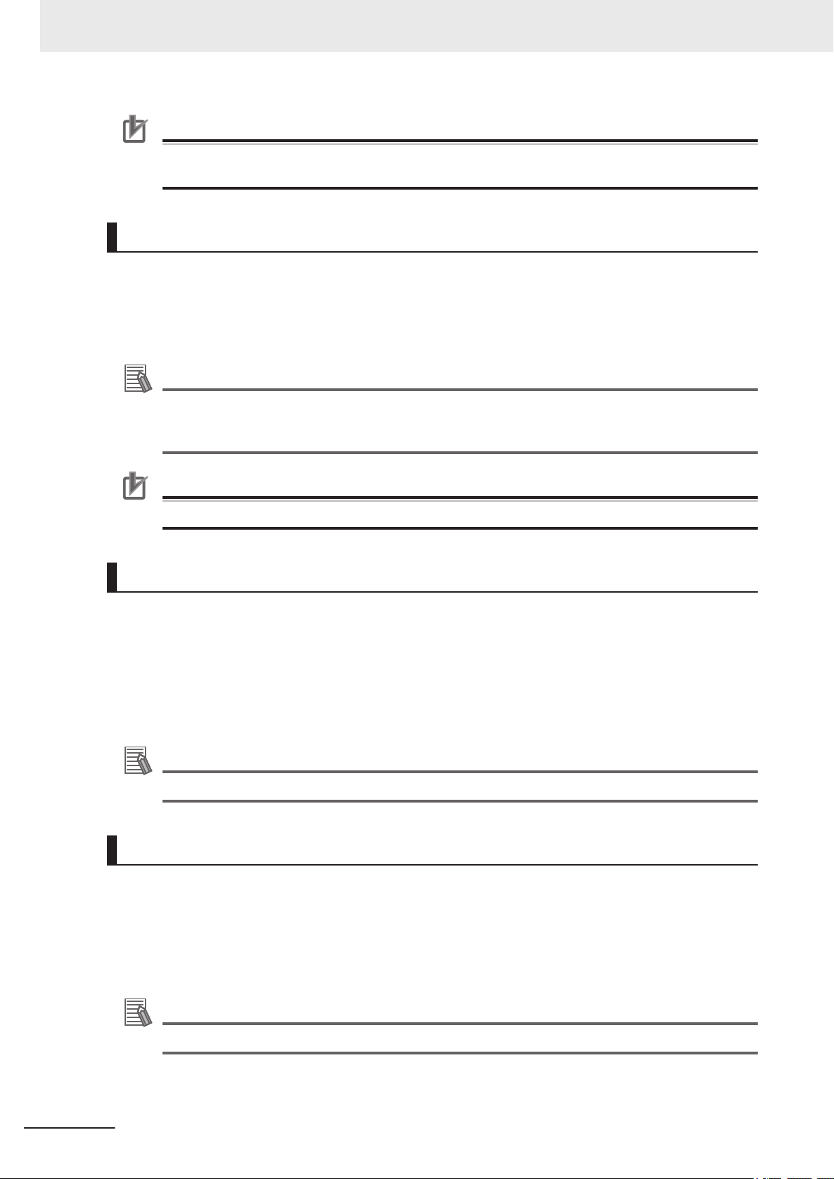
The robot label is described below.
Item Name Description
1
2 Product type The product type is displayed.
3 Alerts and compliance General alerts and compliance information is displayed.
4 Robot information The robot model, weight, maximum payload, and maximum reach is
5 Electrical information General electrical power supply information about the robot is dis-
6 Production information The following information is provided.
*1. Refer to 1-5 Model Numbers on page 1-14 for model information.
Part number
*1
The robot part number is displayed.
displayed.
played.
• M/N indicates the model number and revision level.
• SN indicates the serial number.
• Lot. No. indicates the lot number in the format of DDMYYFF. Month
number 1 to 9 for January to September, X for October, Y for November, and Z for December. FF is reserved for internal use.
• Product origin information is displayed.
1-10
i4L Robots User's Manual (I658)
Page 39

1-3-2
1 2
3
4
5
6
1 Overview
Controller Label
The controller label is described below.
Item Name Description
1
2 Product type The product type is displayed.
3 Alerts and compliance General alerts and compliance information is displayed.
4 Controller information The controller model and general electrical power supply information is
5 MAC Address Reserved for future use.
6 Production information The following information is provided.
*1. Refer to 1-5 Model Numbers on page 1-14 for model information.
Part number
*1
The controller part number is displayed.
displayed.
• SN indicates the serial number.
• Lot. No. indicates the lot number in the format of DDMYYFF. Month
number 1 to 9 for January to September, X for October, Y for November, and Z for December. FF is reserved for internal use.
• Product origin information is displayed.
1-3 Information Labels
1
1-3-2 Controller Label
i4L Robots User's Manual (I658)
1-11
Page 40

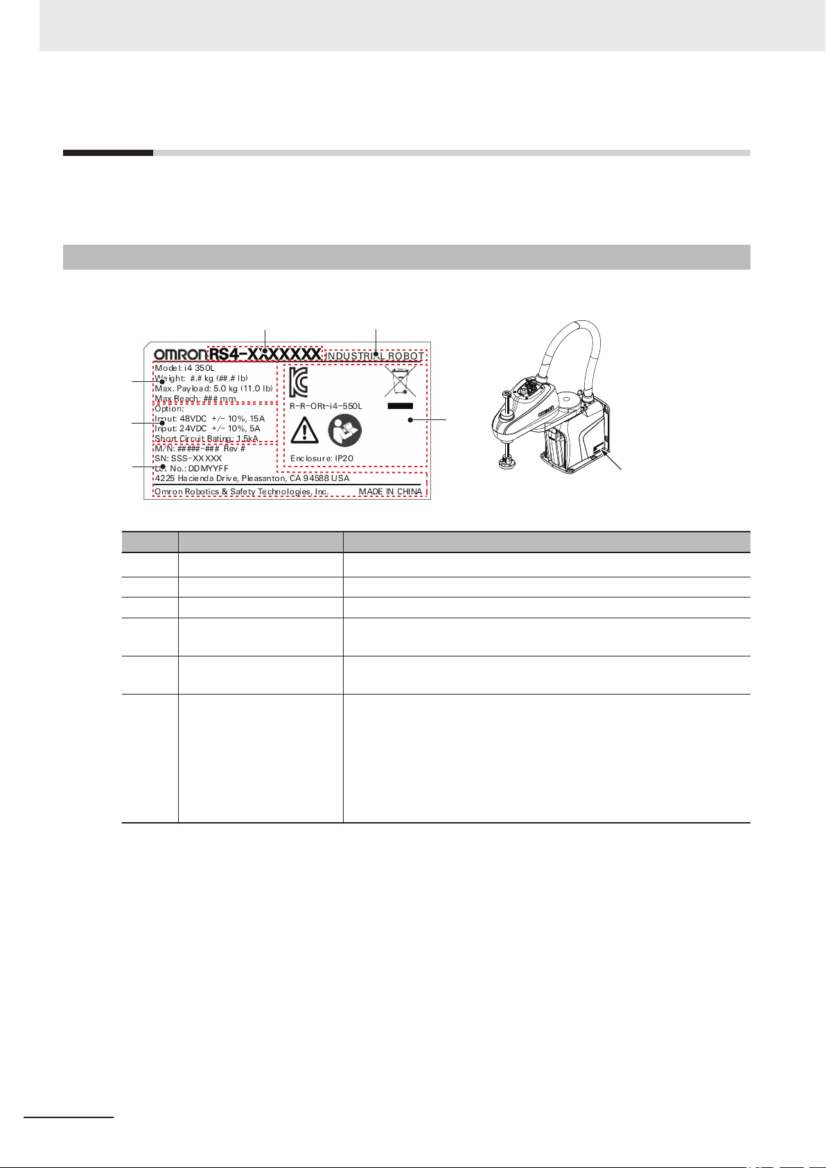
180 mm
350 mm
180 mm
450 mm
180 mm
550 mm
1 Overview
1-4
1-4-1
1-4-2
Robot Configurations
The i4L robot is offered in a variety of configurations with different work envelopes and z-axis stroke
lengths.
i4-350L
The i4-350L configuration has a reach of 350 mm and a z-axis stroke of 180 mm.
i4-450L
1-4-3
The i4-450L configuration has a reach of 450 mm and a z-axis stroke of 180 mm.
i4-550L
The i4-550L configuration has a reach of 550 mm and a z-axis stroke of 180 mm.
1-12
i4L Robots User's Manual (I658)
Page 41

350 mm
550 mm
1 Overview
1-4 Robot Configurations
1-4-4
1-4-5
i4-550L (350 mm Z)
The i4-550L (350 mm Z) configuration has a reach of 550 mm and a z-axis stroke of 350 mm.
1
1-4-4 i4-550L (350 mm Z)
Mounting and Cabling Options
The robot has a table mount flange and a wall mount flange integrated into the base. This allows the
robot to be table-mounted or wall-mounted without the need for additional brackets or adapters.
The rear / bottom Primary Interface Panel orientation options allow cables to exit through the mounting
surface or parallel to the mounting surface as shown below.
i4L Robots User's Manual (I658)
1-13
Page 42

1 Overview
1-5
1-5-1
Model Numbers
Models numbers and descriptions associated with the robot are provided below.
Robot Model Numbers
The table below provides all robot model numbers and descriptions.
Model Number Reach Z-axis Stroke
RS4-2053002 350 mm 180 mm Rear
RS4-2054002 450 mm
RS4-2055002 550 mm
RS4-2055004 550 mm 350 mm
RS4-2053102 350 mm 180 mm Bottom
RS4-2054102 450 mm
RS4-2055102 550 mm
RS4-2055104 550 mm 350 mm
Primary Interface Panel Orien-
tation
1-5-2
Controller Model Numbers
The table below provides all robot controller model numbers and descriptions.
Model Number Description
19354-000 Controller with Ethernet communications support.
1-14
i4L Robots User's Manual (I658)
Page 43

1 Overview
1-6 Optional Hardware
1-6
1-6-1
Optional Hardware
The following optional hardware is available for the robot.
IO Blox
IO Blox units are available to expand the I/O capacity of the robot. Each unit offers 8 inputs and 8 out-
puts. Up to 4 IO Blox units can be added to the robot.
• The part number for an IO Blox unit connected directly to the robot is 90356-30200.
• The part number for IO Blox units connected to another IO Blox unit is 90356-30100.
Additional Information
Refer to 3-7-3 IO Blox Connections on page 3-19 and the Omron Adept IO Blox User's Guide
(04638-000) for more information.
1
1-6-1 IO Blox
1-6-2
T20 Pendant
The T20 pendant is an optional handheld device that allows you to manually jog the robot, teach loca-
tions, and view V+ programs without a PC.
• The part number for the pendant kit is 10054-010. This kit includes the T20 pendant, an adapter ca-
ble (3 m), and a jumper plug.
• The adapter cable includes a round, 17-pin connector that can be panel-mounted. It can be mount-
ed to a surface with up to 6.5 mm of thickness and requires an M23 hole.
Precautions for Correct Use
The T20 pendant can only control the robot it is directly connected to.
Additional Information
Refer to 3-6-1 System Cable Overview on page 3-10 and the T20 Pendant User's Manual
(Cat. No. I601) for more information.
i4L Robots User's Manual (I658)
1-15
Page 44

1 Overview
1-6-3
IPC Application Controller
The IPC Application Controller can be added to your system to execute PackManager and Robot Vi-
sion Manager applications.
The Pack Manager application controls automated pick-and-place systems with cameras, conveyors,
and robots based on the data that you set up in the ACE software. It is executed on the IPC Applica-
tion Controller to control the process data and recipe data.
The Robot Vision Manager application processes images captured by cameras based on the data that
you set up in the ACE Software. It is executed on the IPC Application Controller.
The part number for the IPC Application Controller with ACE Software pre-installed is AC1-152000.
Refer to the following manuals for more information.
• Automation Control Environment (ACE) Version 4 User's Manual (Cat. No. I633)
• IPC Application Controller User's Manual (Cat. No. I632)
1-6-4
1-16
XIO Termination Block
The XIO Termination Block is used to connect digital I/O devices to the robot. This unit provides termi-
nal block connection points for 12 inputs and 8 outputs. LED indicators are provided to indicate
ON/OFF status. Each input has a switch to simulate input signals for troubleshooting or testing pur-
poses.
i4L Robots User's Manual (I658)
Page 45

XIO Cable
XBELTIO
Adapter Cable
Belt Encoder
Y-adapter Cable
XIO Breakout
Cable
EXPIO to
IO Blox Cable
1 Overview
Use the XIO cable to connect the XIO Termination block to the robot. Refer to XIO Cable on page
1-18 for more information.
• The part number for the XIO Termination Block is 90356-40100 (2 m cable included).
• Refer to the Adept XIO Termination Block Installation Guide (00340-000) for more information.
1-6 Optional Hardware
1
1-6-5 Optional Cables
1-6-5
Optional Cables
This section provides information about optional cables that are available.
i4L Robots User's Manual (I658)
1-17
Page 46

1 Overview
XBELTIO Adapter Cable
The optional XBELTIO adapter cable connects to the XBELTIO connector on the Primary Interface
Panel. It provides connections for belt encoder, force sensor, RS-232, and IO Blox signals.
• The part number for this cable is 13463-000.
• The length of this cable is 600 mm.
Belt Encoder Y-adapter Cable
The optional belt encoder Y-adapter cable connects to the XBELTIO adapter cable's BELT ENCODER
connector. This cable provides individual connections for two belt encoder input signals.
• The part number for this cable is 09443-000.
• The length of this cable is 3 m.
Additional Information
Refer to A-5-2 XBELTIO Adapter Cable Pinouts on page A-8 for more information.
Additional Information
Refer to A-5-3 Belt Encoder Y-adapter Cable Pinouts on page A-9 for more information.
XIO Breakout Cable
The optional XIO breakout cable connects to the XIO connector on the Primary Interface Panel and
provides a method to connect I/O devices directly to the robot without using an XIO Termination Block
unit.
• This cable is not compatible with the XIO Termination Block.
• This cable cannot be used together with an XIO cable.
• The part number for this cable is 04465-000.
• The length of this cable is 5 m.
Additional Information
Refer to 3-7-1 XIO Connector Signals and Wiring on page 3-13 for more information.
XIO Cable
1-18
The optional XIO cable connects to the XIO connector on the Primary Interface Panel. It is used to
connect an XIO Termination Block to the system.
• The part number for this cable is 03695-000.
• The length of this cable is 2 m.
Additional Information
Refer to 1-6-4 XIO Termination Block on page 1-16 for more information.
i4L Robots User's Manual (I658)
Page 47

1 Overview
EXPIO to IO Blox Cable
The optional EXPIO to IO Blox cable connects to the XBELTIO adapter cable's FORCE/EXPIO con-
nector. It allows a direct connection between this connector and optional IO Blox units.
• The part number for this cable is 04677-030.
• The length of this cable is 3 m.
1-6 Optional Hardware
Additional Information
Refer to 3-7-3 IO Blox Connections on page 3-19 for more information.
1
1-6-5 Optional Cables
i4L Robots User's Manual (I658)
1-19
Page 48

1 Overview
1-20
i4L Robots User's Manual (I658)
Page 49

2
2
Specifications
This section provides specifications for the robot's hardware, performance, electrical
connections, installation environment, and other technical aspects of the system.
2-1 Physical Specifications .................................................................................2-2
2-1-1 Robot Overall Dimensions............................................................................... 2-2
2-1-2 Mounting Flange Dimensions.......................................................................... 2-4
2-1-3 Tool Flange Dimensions .................................................................................. 2-5
2-1-4 Front Panel Dimensions.................................................................................. 2-5
2-1-5 Robot Work Envelope Dimensions.................................................................. 2-6
2-1-6 Robot Weights................................................................................................. 2-7
2-2 Performance Specifications.......................................................................... 2-8
2-2-1 General Performance Information................................................................... 2-8
2-2-2 Stopping Distances and Times........................................................................ 2-8
2-3 Electrical Specifications.............................................................................. 2-12
2-3-1 Power Supply Specifications......................................................................... 2-12
2-3-2 XIO and TIO Connector I/O Specifications.................................................... 2-12
2-4 Environmental Specifications..................................................................... 2-14
2-5 Other Specifications ....................................................................................2-15
2-5-1 Connector and Port Specifications................................................................ 2-15
2-5-2 Mounting Hardware and Torques .................................................................. 2-15
i4L Robots User's Manual (I658)
2-1
Page 50

30 mm
160 mm
350 mm
61 mm
590 mm
656 mm
+/- 360°
180 mm
232.5 mm
52.5 mm
180 mm
240 mm
2 Specifications
2-1
2-1-1
Physical Specifications
This section provides physical specifications for the i4L robot.
Robot Overall Dimensions
Use the diagrams below to understand the robot's overall physical dimensions.
i4-350L Dimensions
Overall dimensions for the i4-350L are provided below.
2-2
i4L Robots User's Manual (I658)
Page 51
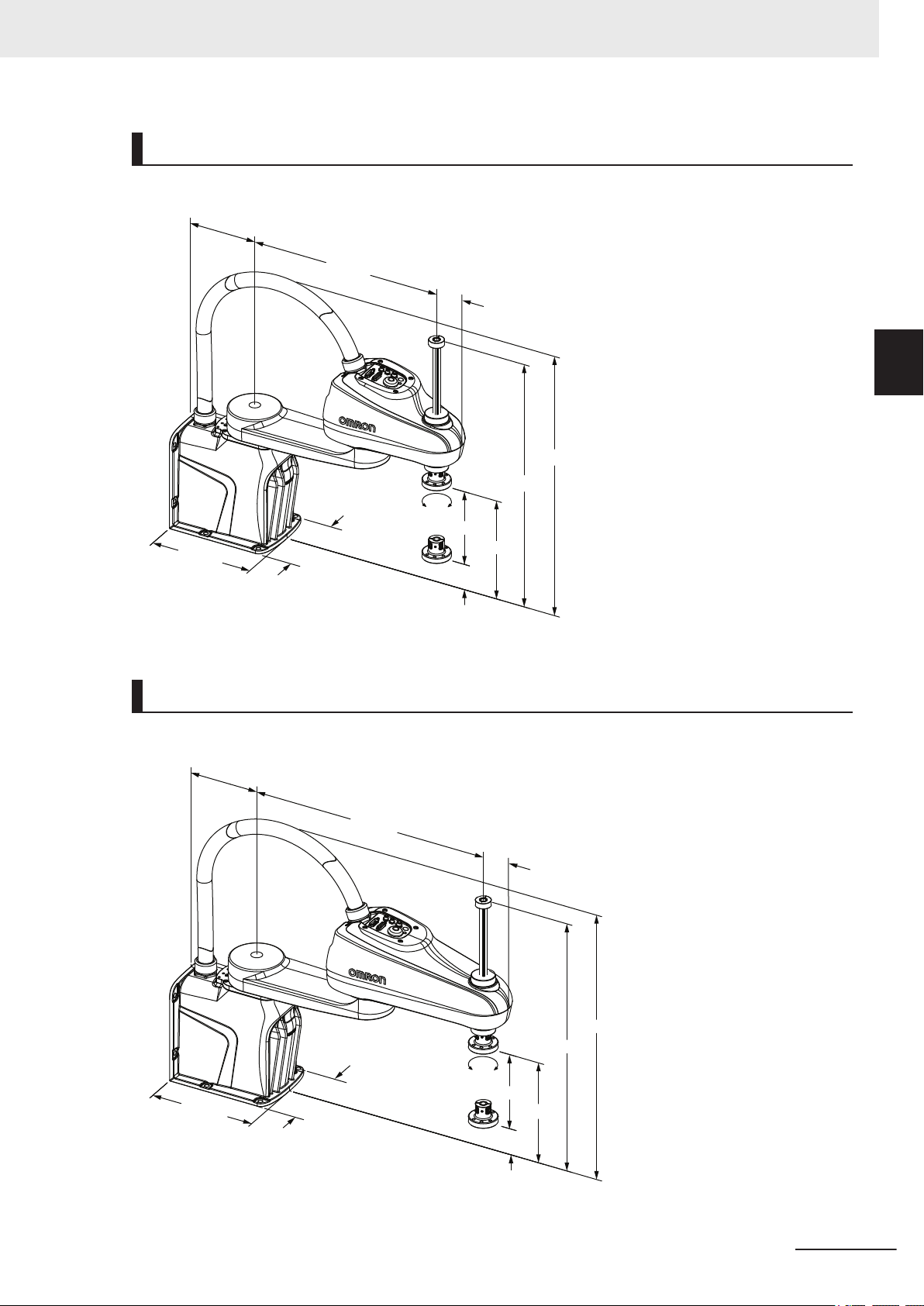
61 mm
600 mm
642 mm
160 mm
450 mm
+/- 360°
180 mm
242.5 mm
62.5 mm
180 mm
240 mm
160 mm
550 mm
61 mm
600 mm
642 mm
62.5 mm
+/- 360°
180 mm
242.5 mm
180 mm
240 mm
2 Specifications
i4-450L Dimensions
Overall dimensions for the i4-450L are provided below.
2-1 Physical Specifications
2
2-1-1 Robot Overall Dimensions
i4-550L Dimensions
Overall dimensions for the i4-550L are provided below.
i4L Robots User's Manual (I658)
2-3
Page 52

240 mm
180 mm
+/- 360°
242.5 mm
350 mm
160 mm
550 mm
61 mm
770 mm
642 mm
4X Ø 9.5 mm THRU
215 mm
180 mm
Ø 6mm 6 mm
85 mm
0
31.5 mm
28.5 mm
Ø 6 mm
+0.020 mm
0
6 mm SLOT
80 mm 0 80 mm
Bottom View
80 mm 0 80 mm
4X Ø 9.5 mm THRU
205 mm
180 mm
Ø 6mm 6 mm
65 mm
31.5 mm
28.5 mm
Ø 6 mm
+0.020 mm
0
6 mm SLOT
0
Rear View
(Top)
(Front)
2 Specifications
i4-550L (350 mm Z) Dimensions
Overall dimensions for the i4-550L (350 mm Z) are provided below.
2-1-2
2-4
Cable Clearances
There must be at least 183 mm of clearance from the Primary Interface Panel connectors to provide
adequate space for cables. These clearances apply to all robot models.
Mounting Flange Dimensions
The robot's mounting flange dimensions are provided below.
Cable Exit Cutout Dimensions
Use the cutout dimensions provided below when cables exit the mounting surface.
i4L Robots User's Manual (I658)
Page 53
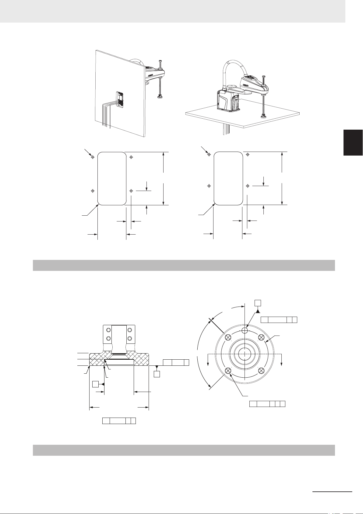
R 20 mm
Mounting
Holes (x4)
20 mm
120 mm
59 mm
220 mm
R 20 mm
Top
Mounting
Holes (x4)
Front
Mounting
Holes (x4)
Mounting
Holes (x4)
120 mm
20 mm
79 mm
220 mm
b 0.02 B
1 mm x 45°
Ø 31.5 mm
+0.025
0
H7
Ø 63 mm
0
-0.046
H8
r
n 0.02 A B
Ø 6 mm
+0.015
0
THRU
j
n 0.040 A B
4 X Ø 5.5 mm THRU
M6 x 1.0 6H THRU
j
n 0.2 A B C
Ø 50 mm
A
C
SECTION A-A
SCALE 1:1
13 mm
6.8 mm
0
1 mm x 45°
A
B
R 0.3 mm
45°
90°
A
2 Specifications
2-1 Physical Specifications
2
2-1-3 Tool Flange Dimensions
2-1-3
Tool Flange Dimensions
The robot's tool flange dimensions are provided below. Geometry and tolerances meet
ISO-9409-1-50-4-M6 (2004) requirements for manipulating industrial robots.
2-1-4
The Front Panel dimensions are provided below.
i4L Robots User's Manual (I658)
Front Panel Dimensions
2-5
Page 54
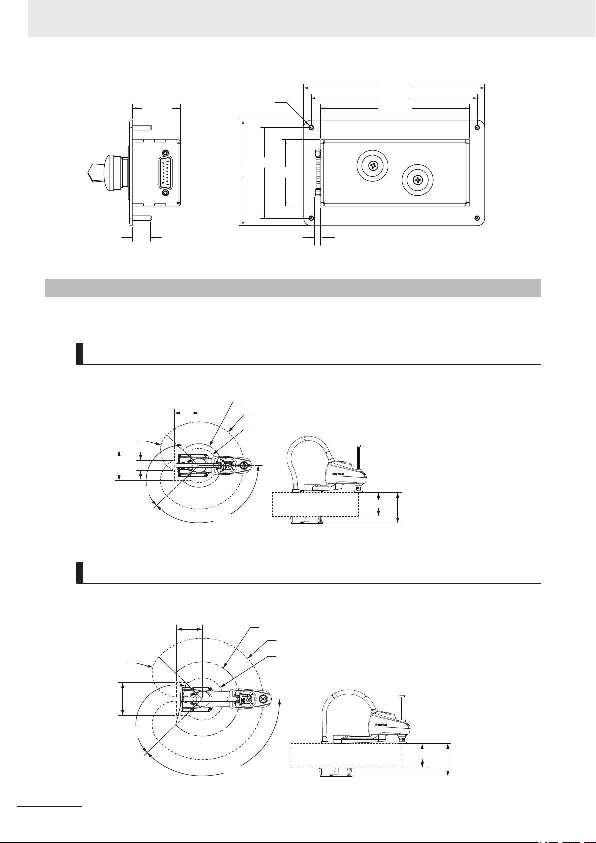
56 mm
76 mm
89 mm
125 mm
152 mm
140 mm
41 mm
16 mm
Ø 4 mm
5 mm
180 mm
232.5 mm
191 mm
R 175 mm
R 350 mm
R 137 mm
135°
135°
245 mm
75 mm
R 175 mm
148°
135°
245 mm
R 175 mm
191 mm
R 275 mm
R 450 mm
R 156.5 mm
180 mm
242.5 mm
2 Specifications
2-1-5
Robot Work Envelope Dimensions
Use the diagrams below to understand the robot's working envelope dimensions.
i4-350L Work Envelope
Work envelope dimensions are provided below.
i4-450L Work Envelope
2-6
Work envelope dimensions are provided below.
i4L Robots User's Manual (I658)
Page 55

20 mm
191 mm
R 275 mm
R 550 mm
R 150 mm
135 °
148°
245 mm
79 mm
R 275 mm
180 mm
242.5 mm
242.5 mm
350 mm
20 mm
191 mm
R 275 mm
R 550 mm
R 150 mm
135 °
148°
245 mm
79 mm
R 275 mm
2 Specifications
i4-550L Work Envelope
Work envelope dimensions are provided below.
i4-550L (350 mm Z) Work Envelope
2-1 Physical Specifications
2
2-1-6 Robot Weights
2-1-6
Work envelope dimensions are provided below.
Robot Weights
Weights for the different robot models are provided in the following table.
i4-350L 15.1 kg
i4-450L 15.9 kg
i4-550L 16.4 kg
i4-550L (350 mm Z) 16.5 kg
Robot Model Weight
i4L Robots User's Manual (I658)
2-7
Page 56

2 Specifications
2-2
2-2-1
Performance Specifications
The following sections provide robot performance specifications.
General Performance Information
The following table provides general performance information for the robot.
Item i4-350L i4-450L i4-550L i4-550L (350 mm Z)
Payload
Reach 350 mm 450 mm 550 mm
Joint Range Joint 1 ±135°
Joint 4 Moment of Inertia
Downward Push Force
burst with no load
Cycle Time
Repeatability at 100%
speed
Joint speeds
(maximum)
*1. Payload is considered as any object(s) attached to a robot link or tool flange including items such as end
*2. Cycle time is defined as a continuous path with straight-line motion cycle in which the robot tool moves up
*1
Joint 2 ±135° ±148°
Joint 3 180 mm 350 mm
Joint 4 ±360°
*2
Joint 1 456 degrees/s
Joint 2 456 degrees/s
Joint 3 800 mm/s
Joint 4 6000 degrees/s
effectors, tooling, valves, grippers, and objects being handled by the robot.
25 mm, over 305 mm, down 25 mm, and then back along the same path (not achievable over all paths in
the robot working envelope). Values listed are for sustained motion, no joint 4 rotation, with a 2 kg payload,
at 20° C ambient temperature.
2 kg rated
5 kg maximum
0.05 kg-m2 maximum
150 N
0.57 s 0.54 s
X, Y: 0.01 mm
Joint 3: 0.01 mm
Joint 4: 0.01°
2-2-2
2-8
Z-axis Quill Bending Moments
When the robot is operating at high payloads with high acceleration / deceleration, the z-axis quill may
be subject to excessive bending moments. Careful considerations must be made under these condi-
tions. Refer to 4-1 Payload and Acceleration Considerations on page 4-2 for more information.
Stopping Distances and Times
The following graphs present information required by Clause 7.2 n of ISO 10218-1. This information
should be used to calculate the safe distance needed when designing and installing safeguarding de-
vices.
i4L Robots User's Manual (I658)
Page 57
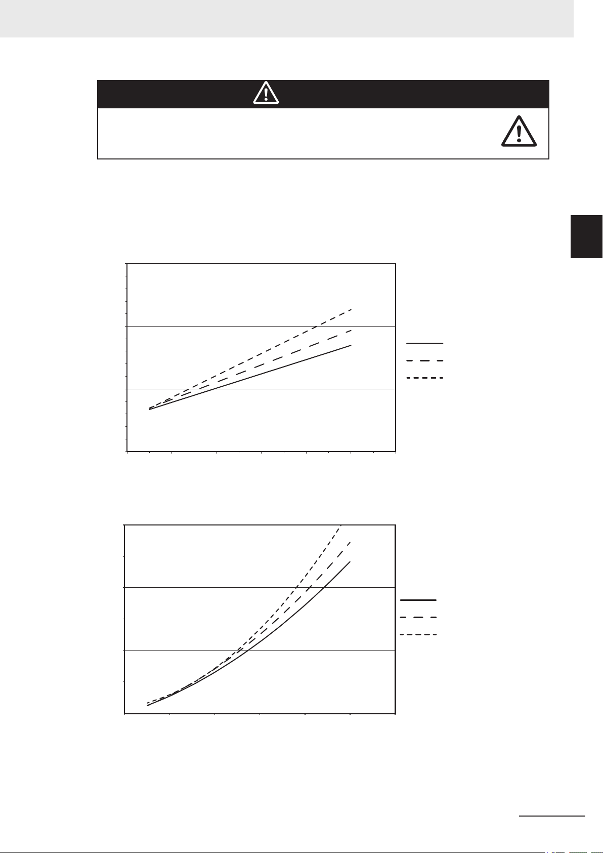
0
0.1
0.2
0.3
0 20 40 60 80 100 120
1.6 kg
3.3 kg
5.0 kg
Stopping Time (s)
Speed (%)
Joint 1 Stopping Time
0
20
40
60
0 20 40 60 80 100 120
Joint 1 Stopping Distance
1.6 kg
3.3 kg
5.0 kg
Speed (%)
Stopping Distance (degrees)
2 Specifications
WARNING
The stopping time and distance, or angle, of a robot joint from initiation of a stop signal is not negligible and must be taken into account when designing and applying
safeguarding devices.
The graphs show the time elapsed and distances traveled between the initiation of a stop signal and
the cessation of all robot motion.
For stop category 1, the stopping time and distance values depend on the speed, load, and extension
of the robot, stated for 33%, 66% and 100% of the maximum payload (5 kg). Data provided is for the
three joints of greatest displacement (J1, J2, and J3).
2-2 Performance Specifications
2
2-2-2 Stopping Distances and Times
i4L Robots User's Manual (I658)
2-9
Page 58

0
0.1
0.2
0.3
0 20 40 60 80 100 120
Joint 2 Stopping Time (all payloads)
Stopping Time (s)
Speed (%)
0
20
40
60
80
100
120
140
0 20 40 60 80 100 120
Joint 2 Stopping Distance (all payloads)
Speed (%)
Stopping Distance (degrees)
0
0.1
0.2
0.3
0 20 40 60 80 100 120
Joint 3 Stopping Time (all payloads)
Stopping Time (s)
Speed (%)
2 Specifications
2-10
i4L Robots User's Manual (I658)
Page 59

0
20
40
60
80
100
120
140
0 20 40 60 80 100 120
Joint 3 Stopping Distance (all payloads)
Speed (%)
Stopping Distance (mm)
2 Specifications
2-2 Performance Specifications
2
2-2-2 Stopping Distances and Times
i4L Robots User's Manual (I658)
2-11
Page 60

2 Specifications
2-3
2-3-1
Electrical Specifications
Electrical specifications are provided in the sections below.
Power Supply Specifications
Specifications for the 24 VDC and 48 VDC power supplies are provided below.
24 VDC Control Power Supply Specifications
Item Specification
Supply voltage range 24 VDC ±10%
Current / power requirements 5 A / 120 W maximum
Circuit protection User-supplied 5 A in-line fuse
Wire size
Shielding User-supplied connection from power supply cable shield to robot ground
0.75 mm2 to 2.5 mm
point.
2
2-3-2
48 VDC High Power Supply Specifications
Item Specification
Supply voltage range 48 VDC ±10%
Current / power requirements 20 A / 960 W maximum
Circuit protection User-supplied 12 A slow-burn, in-line fuse
Wire size
Shielding User-supplied connection from power supply cable shield to robot ground
2.5 mm
point
2
XIO and TIO Connector I/O Specifications
Specifications for the XIO and TIO connector input and output circuits are provided below.
Type Item Specification
Input circuits Type Sinking / Sourcing
Operational voltage range 0 to 30 VDC
OFF state voltage range 0 to 3 VDC
ON state voltage range 10 to 30 VDC
Typical threshold voltage 8 VDC
Operational current range 0 to 7.5 mA
OFF state current range 0 to 0.5 mA
ON state current range 2.5 to 6 mA
Typical threshold current 2.0 mA
Impedance (Vin / Iin) 39 kΩ
2-12
Current at 24 VDC < 6 mA
ON response time (hardware) 5 µs
OFF response time (hardware) 5 µs
i4L Robots User's Manual (I658)
Page 61

2 Specifications
Type Item Specification
Output circuits Type Sourcing
Output voltage range 24 VDC ±10%
Total current output for all XIO circuits
Total current output for all TIO circuits
ON state resistance at 0.5A 0.14Ω maximum at 85° C
Output leakage current 5 µA maximum
ON response time (hardware) 30 µs
OFF response time (hardware) 38 µs
Short circuit current limit 0.7 to 2.5 A
Output voltage at inductive load
(turn OFF)
1.0 A maximum at 50° C ambient temperature
1.5 A maximum at 25° C ambient temperature
1.0 A maximum at 50° C ambient temperature
1.5 A maximum at 25° C ambient temperature
(+V - 52) ≤ V
0.5 A and load ≥ 1 mH
≤ (+V - 41) where I
demag
out
2-3 Electrical Specifications
2
2-3-2 XIO and TIO Connector I/O Specifications
=
i4L Robots User's Manual (I658)
2-13
Page 62

2 Specifications
2-4
Environmental Specifications
Environmental specifications are provided below.
WARNING
To reduce the risk of fire or electric shock, install the robot in a controlled environment
relatively free of contaminants.
Item Specification
Ambient operating temperature 5 to 40°C
Storage temperature –25 to 55°C
Humidity 5 to 90%, non-condensing
Altitude 2000 m maximum
Pollution degree 2
Protection class IP20 / NEMA Type 1
2-14
i4L Robots User's Manual (I658)
Page 63

2 Specifications
2-5
2-5-1
Other Specifications
Other specifications for associated equipment are provided below.
Connector and Port Specifications
Robot connector specifications are provided below.
Additional Information
Refer to Section 3 Installation on page 3-1 for more information about connector wiring and
pin diagrams.
Connector Specification
Pneumatic pass-through ports Push-connect type fittings with a maximum air pres-
sure of 0.55 MPa
• Port A and B fittings: 6 mm
• Port C fitting: 4 mm
USER connectors 15 pin, D-sub, male
Rated current: 3 A
Control Power connector Molex 2-wire receptacle
Part number: 43160-2102
High Power connector Molex 3-wire receptacle
Part number: 43160-2103
XSYSTEM connector 44 pin, D-sub HD, female
XBELTIO connector 26 pin, D-sub HD, male
XIO connector 26 pin, D-sub HD, female
Ethernet interface port RJ-45
TIO connector 15 pin, D-sub, female
2-5 Other Specifications
2
2-5-1 Connector and Port Specifications
2-5-2
i4L Robots User's Manual (I658)
Mounting Hardware and Torques
The following bolt types, washers, and torque is required for mounting the robot.
Type Quantity Size Class Torque
Socket Head Cap
Screw
Flat Washer 4
The robot's center of mass can cause the robot to fall over if the robot is not properly
secured with the mounting bolts.
4
• M8 x 1.25 mm
• DIN 912 or ISO 4782
• M8
• DIN 125 or ISO 7089
10.9 or 12.9 30-32 N-m
8.8 –-
WARNING
2-15
Page 64

2 Specifications
2-16
i4L Robots User's Manual (I658)
Page 65

Installation
3
3
This section provides information about installing the robot and other necessary equipment.
3-1 Robot Installation Procedure ........................................................................ 3-2
3-2 Mounting the Robot .......................................................................................3-3
3-2-1 Robot Mounting Surface.................................................................................. 3-3
3-2-2 Mounting Procedure........................................................................................ 3-3
3-3 Installing End-of-Arm Tooling ....................................................................... 3-5
3-4 Installing Optional Equipment ......................................................................3-6
3-4-1 Mounting External Equipment to the Robot..................................................... 3-6
3-5 Adjustable Hardstops ....................................................................................3-7
3-5-1 Joint 1 Adjustable Hardstops........................................................................... 3-8
3-5-2 Joint 2 Adjustable Hardstops........................................................................... 3-8
3-5-3 Joint 3 Adjustable Hardstop ............................................................................ 3-8
3-6 System Cable Installation............................................................................ 3-10
3-6-1 System Cable Overview................................................................................ 3-10
3-6-2 System Cable Installation Procedure ............................................................ 3-12
3-7 Connecting Digital I/O.................................................................................. 3-13
3-7-1 XIO Connector Signals and Wiring................................................................ 3-13
3-7-2 TIO Connector Signals and Wiring................................................................ 3-17
3-7-3 IO Blox Connections...................................................................................... 3-19
3-8 Installing Safety Equipment ........................................................................ 3-20
3-8-1 Installing the Front Panel............................................................................... 3-20
3-8-2 Safety Circuits ............................................................................................... 3-21
3-9 Supplying Power and Ground..................................................................... 3-28
3-9-1 Grounding the System................................................................................... 3-28
3-9-2 24 VDC Connections..................................................................................... 3-29
3-9-3 48 VDC Connections..................................................................................... 3-29
3-10 Verifying Installation.................................................................................... 3-31
3-10-1 Mechanical Checks ....................................................................................... 3-31
3-10-2 System Cable Checks ................................................................................... 3-31
3-10-3 Safety Equipment Checks ............................................................................. 3-31
3-10-4 Switch Position Checks ................................................................................. 3-33
i4L Robots User's Manual (I658)
3-1
Page 66

3 Installation
3-1
Robot Installation Procedure
The basic installation steps are provided below.
WARNING
• Ensure that installation and post-installation checks of the product are performed by
personnel in charge who possess a thorough understanding of the machinery to be
installed.
• The robot must be installed to avoid interference with buildings, structures, utilities,
other machines and equipment that may create trapping or pinch points. It must be
installed in accordance with Standard for Robots and Robotic Devices – Safety Requirements for Industrial Robots – Part 2: Robot Systems and Integration, ISO
10218-2.
Additional Information
Refer to A-1 Unpacking and Inspecting the Robot on page A-2 for more information.
1 Mount the robot.
Refer to 3-2 Mounting the Robot on page 3-3 for more information.
2 Install the end-of-arm tooling.
Refer to 3-3 Installing End-of-Arm Tooling on page 3-5 for more information.
3 Install any equipment such as cameras, solenoid valves, a Front Panel, or bellows.
Refer to 3-4 Installing Optional Equipment on page 3-6 for more information.
Connect any necessary pneumatic air lines using the pass-through ports.
4
Refer to 2-5-1 Connector and Port Specifications on page 2-15 for more information.
5 Make any necessary adjustments to hardstops.
Refer to 3-5 Adjustable Hardstops on page 3-7 for more information.
6 Connect all required system cables.
Refer to 3-6 System Cable Installation on page 3-10 and 3-7 Connecting Digital I/O on page
3-13 for more information.
7 Connect all required safety equipment.
Refer to 3-8 Installing Safety Equipment on page 3-20 for more information.
Make power and ground connections.
8
Refer to 3-9 Supplying Power and Ground on page 3-28 for more information.
3-2
9 Verify the robot installation.
Refer to 3-10 Verifying Installation on page 3-31 for more information.
i4L Robots User's Manual (I658)
Page 67

3 Installation
3-2
3-2-1
Mounting the Robot
Use the information in the following sections to mount the robot.
Robot Mounting Surface
The following considerations must be made when preparing a robot mounting surface.
• It must be smooth and flat.
• It must be rigid enough to prevent vibration and flexing that is caused by reactionary forces during
fast robot motion.
• It must be designed to support the weight of the robot with payload.
• Table-mounted robots must be placed on a level, horizontal surface.
• Wall-mounted robots must be fastened to a 90° vertical surface.
• When the robot is mounted to a vertical surface, considerations for preventing a collision with the
mounting surface should be made.
WARNING
If a robot is mounted to a surface with inadequate stiffness, damage to the z-axis quill
or other mechanical components can result from excessive oscillation during operation.
3-2 Mounting the Robot
3
3-2-1 Robot Mounting Surface
3-2-2
Precautions for Correct Use
• It is recommended to use a properly secured, 18 mm (minimum) thick steel plate with a maximum surface roughness of 25 μm as a robot mounting surface.
• Keep a minimum of 300 mm clearance from the Primary Interface Panel to allow for switch
and cable connection access.
Mounting Procedure
Use the following procedure to mount the robot.
WARNING
• Always use proper lifting technique when lifting the robot. Failure to comply could
result in the robot falling and causing either personnel injury or equipment damage.
• The robot's center of mass can cause the robot to fall over if the robot is not properly secured with the mounting bolts.
Precautions for Safe Use
The robot can be lifted by hand. Only use the base and inner link when lifting the robot. Never
maneuver the robot using the quill or flyover assemblies.
Precautions for Correct Use
The mounting surface should be clean and prepared according to the information provided in
3-2-1 Robot Mounting Surface on page 3-3 before attempting to mount the robot.
i4L Robots User's Manual (I658)
3-3
Page 68

3 Installation
Before beginning the mounting procedure, have the following tools and resources available. Prepare
the mounting holes before beginning the mounting procedure.
• Prepare the mounting holes.
• A torque wrench for proper tightening of the mounting bolts.
• Assistance to lift and maneuver the robot into the mounting position.
• Four socket-head cap screws with flat washers. Refer to 2-5-2 Mounting Hardware and Torques on
page 2-15 for more information.
1 Using the dimensions provided in 2-1-2 Mounting Flange Dimensions on page 2-4, prepare
2
3
four holes in the mounting surface to accommodate the user-supplied machine bolts (specified
above). A slot and hole are provided in the mounting flange for dowel pins.
Maneuver the robot into position on the mounting surface.
Align the holes in the mounting flange with the prepared mounting holes in the mounting sur-
face.
Insert all four bolts with washers to secure the robot to the mounting surface.
4
Tighten the four bolts to 31 N-m of torque.
5
Additional Information
After mounting the robot, check the mounting bolt torque after 72 hours of initial operation and then recheck every 3 months thereafter. Refer to 6-2 Periodic Maintenance on
page 6-3 for more information.
6 After all four bolts have been tightened to the specified torque, the mounting procedure is com-
plete.
3-4
i4L Robots User's Manual (I658)
Page 69

3 Installation
3-3
Installing End-of-Arm Tooling
3-3 Installing End-of-Arm Tooling
You must provide, install, and ground (if necessary) end-of-arm tooling to the tool flange.
Use the following details when designing and installing end-of-arm tooling.
• Hole diameters and placement on the tool flange comply with ISO-9409-1-50-4-M6 (2004) stand-
ards.
• End-of-arm tooling is attached to the tool flange using M6 x 1.0 (Class 10.9 or higher) screws with a
minimum of 10 mm thread engagement into the tool flange.
• Apply Loctite 243 thread lock (or equivalent) to secure the screws.
• Apply a torque of 7.5 N-m when tightening tooling screws.
Additional Information
3
Refer to 2-1-3 Tool Flange Dimensions on page 2-5 for more information.
If the end-of-arm tooling requires pneumatic or electrical connections, use the pass-through connec-
tions from the Primary Interface Panel to the Secondary Interface Panel. Refer to 1-2-3 Connectors on
page 1-7 for more information.
Precautions for Safe Use
The Joint 3 quill and the tool flange are not grounded to protective earth. If hazardous voltages
are present at any user-supplied robot-mounted equipment or tooling, you must install a ground
connection from that equipment or tooling to the ground point on the robot base.
Refer to 3-9-1 Grounding the System on page 3-28 for more information about grounding the
tool flange.
DANGER
Failure to ground robot-mounted equipment or tooling that uses hazardous voltages
could lead to injury or fatality of a person touching the end-effector during an electrical
fault.
i4L Robots User's Manual (I658)
3-5
Page 70

(4X) M4 X 0.7 6H THRU
6.5 mm max. thread engagement
(2X) M5 x 0.8 6H 7.5
20.5 mm
14 mm
0
20.5 mm
14 mm
86.6 mm
70 mm
0
34 mm
Bottom Surface
(Outer Link)
3 Installation
3-4
3-4-1
Installing Optional Equipment
This section provides information about installing the following optional equipment.
Mounting External Equipment to the Robot
The robot body has accommodations to mount external equipment such as a camera or solenoid
valves. Use the information below to understand how to mount external equipment to the robot.
4 mounting holes are provided on the bottom of the outer link between joint 2 and joint 4.
2 mounting holes are provided on the bottom and near the end of the outer link.
The following considerations should be made when mounting external equipment to the robot.
• Do not mount equipment that will interfere with robot motion or other objects in the work cell.
• Do not mount equipment in a way that can induce excessive inertia to the outer link.
• Mounting holes are thru-type and the robot body is 6.5 mm thick. Do not use fasteners that can ex-
tend into the body of the robot. This can interfere with internal components.
Precautions for Correct Use
Any externally mounted equipment is considered robot payload. Consideration to the payload
attached to the Tool Flange should be made when mounting external equipment to the robot.
Apply a torque of 2.5 N-m to the user-supplied fasteners when mounting equipment to the 4 mounting
holes between joint 2 and joint 4. Apply Loctite thread lock type 222 or equivalent.
Apply a toque of 4.5 N-m to the user-supplied fasteners when mounting equipment to the 2 mounting
holes at the end of the outer link. Apply Loctite thread lock type 243 or equivalent.
3-6
i4L Robots User's Manual (I658)
Page 71

1
2
3
4
5
6
7
3 Installation
3-5
Adjustable Hardstops
The robot is equipped with several mechanical hardstop adjustment points for joints 1, 2, and 3 as de-
scribed in the following sections. Adjust these mechanical hardstops to restrict the robot's range of
motion in order to prevent collisions within the workspace if necessary.
WARNING
The robot's physical hardstop devices are not intended to withstand repeated use and
if this occurs, the hardstop may become damaged. Implement proper programming
and configuration of joint range limits to prevent hardstop impacts.
Precautions for Correct Use
Always reduce joint motion limits with software configuration settings when hardstops are used
to restrict range of motion. Refer to the Automation Control Environment (ACE) Version 4
User's Manual (Cat. No. I633) for more information.
Additional Information
• Obstacles may be defined with software configuration to restrict the robot tool-tip from entering specified volumes of the work envelope. Refer to the Automation Control Environment
(ACE) Version 4 User's Manual (Cat. No. I633) for more information.
• Refer to 2-1-5 Robot Work Envelope Dimensions on page 2-6 for full range of motion values.
3-5 Adjustable Hardstops
3
3-5-1 Joint 1 Adjustable Hardstops
i4L Robots User's Manual (I658)
3-7
Page 72

3 Installation
3-5-1
Joint Hardstop
Position
1 Joint 1 -109.5°
2 +109.5°
3 Joint 2 -124° -118°
4 +124° +118°
5
6 +133°
7 Joint 3 5 mm from end of travel.
*1. The i4-350L model includes pre-installed hardstop screws in positions 5 and 6 to prevent base interference
with the quill. Do not remove these pre-installed hardstop screws.
Joint Limita-
tion
i4-350L i4-450L i4-550L / i4-550L (350 mm Z)
See note
*1
Range of Motion Software Limit Setting
-133°
Joint 1 Adjustable Hardstops
Use the following information when making joint 1 hardstop adjustments.
• Four M8 X 10 socket head cap screws, class 12.9 are supplied with the robot for use as Joint 1 and
Joint 2 adjustable hardstops.
• Apply Loctite thread lock type 243 or equivalent.
• Apply a torque of 17 N-m when tightening the hardstop screws.
3-5-2
3-5-3
Joint 2 Adjustable Hardstops
Use the following information when making joint 2 hardstop adjustments.
• Four M8 X 10 socket head cap screws, class 12.9 are supplied with the robot for use as Joint 1 and
Joint 2 adjustable hardstops.
• Apply Loctite thread lock type 243 or equivalent.
• Apply a torque of 17 N-m when tightening the hardstop screws.
Joint 3 Adjustable Hardstop
The joint 3 down stroke can be limited by sliding the clamp collar down the z-axis quill to a lower posi-
tion.
The following tools are required when adjusting the joint 3 hardstop.
• 4 mm hex bit
• Torque wrench
• Loctite thread lock type 243 or equivalent
•
Precautions for Correct Use
Never loosen or remove the quill clamp collar while the z-axis brake is released.
3-8
i4L Robots User's Manual (I658)
Page 73
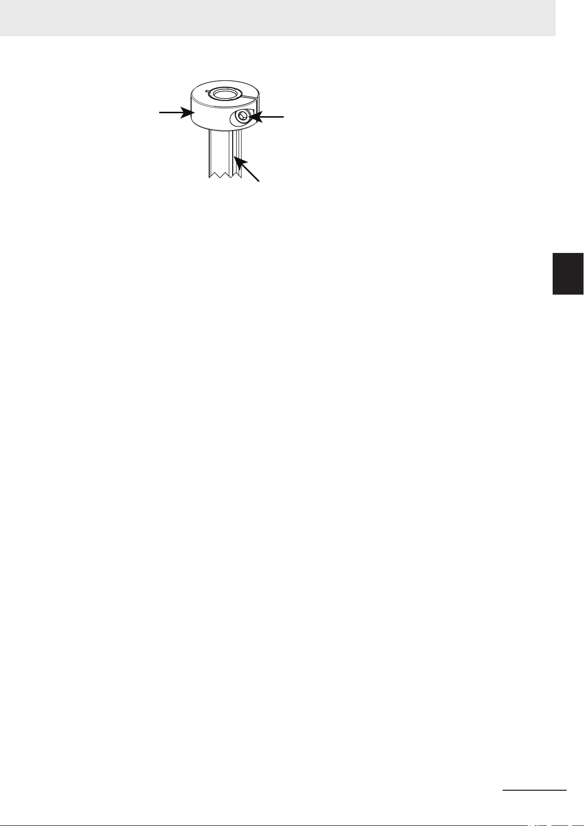
Clamp Collar
Socket-head
Screw
Z-axis Quill
(Top End)
3 Installation
Loosen the clamp collar socket-head screw and slide the clamp to the appropriate location to limit the
down stroke of the z-axis quill. When the clamp is in the desired location, apply thread lock and tighten
the socket-head screw to a torque of 4.5 N-m.
3-5 Adjustable Hardstops
3
3-5-3 Joint 3 Adjustable Hardstop
i4L Robots User's Manual (I658)
3-9
Page 74

3 Installation
3-6
3-6-1
System Cable Installation
This section provides information about installing the robot system cables.
WARNING
• Never connect or disconnect system cables while power is applied to the robot.
Failure to comply may cause unexpected behavior and can result in personnel injury and equipment damage.
• Provide appropriately-sized Branch Circuit Protection and Lockout / Tagout Capability in accordance with the National Electrical Code and any local codes.
• Ensure that interconnecting cables or pneumatic lines are routed away from the robot workspace.
System Cable Overview
Standard and optional cable connections are provided below.
Standard Connections
The following figure shows standard connections with the XSYSTEM cable. This cable is supplied with
the robot.
Additional Information
Refer to 3-8 Installing Safety Equipment on page 3-20 for more information about XFP, XUSR,
and XMCP connections.
3-10
i4L Robots User's Manual (I658)
Page 75

T20 Pendant
XSYSTEM
Cable
Front
Panel
Front Panel
Extension Cable
T20 Pendant
Adapter Cable
T20 Pendant
Jumper Plug
XUSR
Connector
XFP
Connector
XMCP
Connector
3 Installation
3-6 System Cable Installation
3
3-6-1 System Cable Overview
Optional Connections
The following figure shows optional connections to the robot.
Additional Information
Refer to 3-7 Connecting Digital I/O on page 3-13 for more information about connecting I/O
with IO Blox Units or with the XIO connector.
i4L Robots User's Manual (I658)
3-11
Page 76

XIO Cable
XBELTIO
Adapter Cable
Belt Encoder
Y-adapter Cable
XIO Breakout
Cable
EXPIO to
IO Blox Cable
3 Installation
3-6-2
System Cable Installation Procedure
The following procedure provides details about system cable installation.
The robot must be mounted before following the steps below. Refer to 3-2 Mounting the Robot on
page 3-3 for more information.
1 Connect the XSYSTEM cable to the Primary Interface Panel XSYSTEM connector and route
the XFP, XUSR, and XMCP connectors to their appropriate locations.
Connect any digital I/O to the XIO and TIO connectors.
2
Refer to 3-7 Connecting Digital I/O on page 3-13 for more information.
Connect external equipment such as the Front Panel and Teach Pendant to the XSYSTEM ca-
3
ble XFP and XMCP connectors.
Refer to 3-6-1 System Cable Overview on page 3-10 for more information.
4 Connect all user-supplied safety equipment to the XUSR connector on the XSYSTEM cable.
Refer to 3-8 Installing Safety Equipment on page 3-20 for more information.
5 If applicable, connect devices to the XBELTIO connector and the USER connectors.
Refer to Optional Connections on page 3-11 for more information.
3-12
i4L Robots User's Manual (I658)
Page 77

PIN 9
PIN 18
PIN 26
PIN 1
PIN 10
PIN 19
3 Installation
3-7
3-7-1
Connecting Digital I/O
The following sections describe the various methods to connect digital I/O to the robot.
XIO Connector Signals and Wiring
The XIO connector on the Primary Interface Panel provides access to built-in digital I/O.
The 12 available inputs correspond to V+ signal numbers 1097 to 1108.
The 8 available outputs correspond to V+ signal numbers 0097 to 0104.
The XIO connector pin assignments are provided below. The Designation and Signal Bank information
in the table below only apply when using an XIO Termination Block.
Additional Information
Refer to 2-3-2 XIO and TIO Connector I/O Specifications on page 2-12 for electrical specifications. Refer to 2-5-1 Connector and Port Specifications on page 2-15 for connector specifications.
3-7 Connecting Digital I/O
3
3-7-1 XIO Connector Signals and Wiring
Pin Number Designation Signal Bank V+ Signal Number
1 Ground --
2 24 VDC
3 Common 1 1 --
4 Input 1.1 1001
5 Input 2.1 1002
6 Input 3.1 1003
7 Input 4.1 1004
8 Input 5.1 1005
9 Input 6.1 1006
10 Ground --
11 24 VDC
12 Common 2 2 --
13 Input 1.2 1007
14 Input 2.2 1008
15 Input 3.2 1009
16 Input 4.2 1010
17 Input 5.2 1011
18 Input 6.2 1012
i4L Robots User's Manual (I658)
3-13
Page 78

Internal Circuits
Input 1.1
Input 1.2
Input 1.3
Input 1.4
Input 1.5
Input 1.6
Common 1
Common 2
Input 2.1
Input 2.2
Input 2.3
Input 2.4
Input 2.5
Input 2.6
3 Installation
19 Output 1 -- 1
20 Output 2 2
21 Output 3 3
22 Output 4 4
23 Output 5 5
24 Output 6 6
25 Output 7 7
26 Output 8 8
XIO Internal Circuits
Use the following information to understand the XIO internal circuits.
Pin Number Designation Signal Bank V+ Signal Number
XIO Input Signals
The twelve inputs are arranged in two banks of six. Each bank is electrically isolated from the other
bank. Each input is optically isolated. The six inputs within each bank share a common source /
sink line.
3-14
XIO Output Signals
The eight outputs share a common, sourcing driver integrated circuit. The driver is designed to sup-
ply a load with one side connected to ground. Each channel is capable of switching up to 0.7 A of
current. This driver has over-temperature protection, shorted load protection, and is current limiting.
The driver draws power from the 24 VDC Control Power supplied to the robot through a self-reset-
ting polyfuse.
i4L Robots User's Manual (I658)
Page 79

Internal Circuits
+24 VDC
Output 1
Output 2
Output 3
Output 4
Output 5
Output 6
Output 7
Output 8
PIN 9
PIN 18
PIN 26
PIN 1
PIN 10
PIN 19
3 Installation
Precautions for Safe Use
Output 8 can be assigned to indicate the robot's High Power state. When High Power is enabled, this output will turn ON. When High Power is not enabled, this output will be OFF. This is
not a safety-rated means of indicating a High Power state and should only be used for monitoring the robot status. Use the ACE software to make this configuration if needed.
Precautions for Correct Use
Use surge suppression when switching inductive loads such as relays to prevent damage to the
output circuits.
Additional Information
If there is an output short or other over-current condition, the affected output of the driver integrated circuit turns OFF until the condition is removed.
3-7 Connecting Digital I/O
3
3-7-1 XIO Connector Signals and Wiring
XIO Breakout Cable Pinouts
Use the following diagrams for XIO Breakout cable pinout information.
i4L Robots User's Manual (I658)
Pin Number Signal Wire Color
1 GND White
2 24 VDC White / Black
3 Common 1 Red
4 Input 1.1 Red / Black
3-15
Page 80

3 Installation
Pin Number Signal Wire Color
5 Input 2.1 Yellow
6 Input 3.1 Yellow / Black
7 Input 4.1 Green
8 Input 5.1 Green / Black
9 Input 6.1 Blue
10 GND Blue / White
11 24 VDC Brown
12 Common 2 Brown / White
13 Input 1.2 Orange
14 Input 2.2 Orange / Black
15 Input 3.2 Gray
16 Input 4.2 Gray / Black
17 Input 5.2 Violet
18 Input 6.2 Violet / White
19 Output 1 Pink
20 Output 2 Pink / Black
21 Output 3 Light blue
22 Output 4 Light blue / Black
23 Output 5 Light green
24 Output 6 Light green / Black
25 Output 7 White / Red
26 Output 8 White / Blue
Shell Shield
XIO Termination Block
An XIO termination block can be connected directly to the XIO connector to provide simple wiring and
access to the built-in I/O.
Additional Information
Refer to the Adept XIO Termination Block Installation Guide (00340-000) for more information.
3-16
i4L Robots User's Manual (I658)
Page 81

PIN 1
PIN 15
PIN 8
PIN 9
3 Installation
3-7 Connecting Digital I/O
3
3-7-2 TIO Connector Signals and Wiring
3-7-2
TIO Connector Signals and Wiring
The TIO connector on the Secondary Interface Panel provides access to built-in digital I/O.
The 5 available inputs correspond to V+ signal numbers 1033 to 1037.
The 4 available outputs correspond to V+ signal numbers 33 to 36.
The TIO connector pin assignments are provided below.
Additional Information
Refer to 2-3-2 XIO and TIO Connector I/O Specifications on page 2-12 for electrical specifications.
Refer to 2-5-1 Connector and Port Specifications on page 2-15 for connector specifications.
Pin Number Designation V+ Signal Number
1 Common –-
2 Input 5 1037
3 Input 2 1034
4 Input 4 1036
5 24 VDC –-
6 Output 3 35
i4L Robots User's Manual (I658)
3-17
Page 82
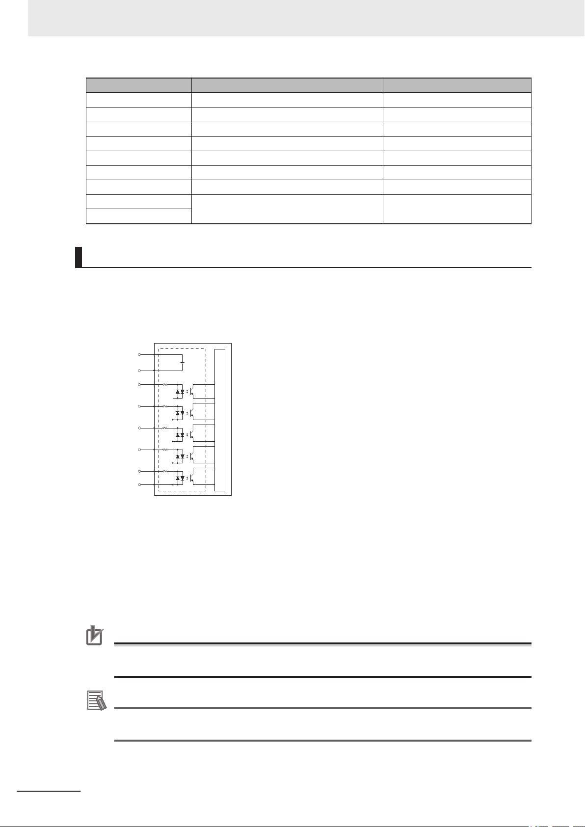
Internal Circuits
Input 1
Input 2
Input 3
Input 4
Input 5
Common
24 VDC
Ground
3 Installation
7 Output 4 36
8 Ground –-
9 Input 1 1033
10 Input 3 1035
11 Ground –-
12 Output 1 33
13 Output 2 34
14 Ground –-
15
TIO Internal Circuits
Use the following diagram to understand the TIO internal circuits.
Pin Number Designation V+ Signal Number
TIO Input Signals
The 5 input channels are optically isolated and share a common source / sink line.
3-18
TIO Output Signals
The 4 outputs share a common, sourcing driver integrated circuit. The driver is designed to supply
a load with one side connected to ground. Each channel is capable of switching up to 0.7 A of cur-
rent. This driver has over-temperature protection, shorted load protection, and is current limiting.
The driver draws power from the primary 24 VDC input to the robot through a self-resetting poly-
fuse.
Precautions for Correct Use
Use surge suppression when switching inductive loads such as relays to prevent damage to the
output circuits.
Additional Information
If there is an output short or other over-current condition, the affected output of the driver integrated circuit turns OFF until the condition is removed.
i4L Robots User's Manual (I658)
Page 83

Internal Circuits
+24 VDC
Output 1
Output 2
Output 3
Output 4
XBELTIO
Adapter Cable
EXPIO to
IO Blox Cable
3 Installation
3-7 Connecting Digital I/O
3-7-3
IO Blox Connections
IO Blox units can be connected to the XBELTIO connector using the XBELTIO adapter cable. Up to 4
IO Blox units can be connected as shown below.
Additional Information
Refer to the Omron Adept IO Blox User's Guide (04638-000) for more information.
3
3-7-3 IO Blox Connections
i4L Robots User's Manual (I658)
3-19
Page 84

3 Installation
3-8
Installing Safety Equipment
The user-supplied safety equipment connects to the system through the XMCP, XUSR and XFP con-
nectors on the XSYSTEM cable. Refer to the following sections for safety equipment connection de-
tails.
DANGER
• The robot system must be installed with user-supplied interlock barriers. The interlocked barriers must open the E-Stop circuit in the event of personnel attempting to
enter the work cell when High Power is enabled. Failure to install suitable guarding
or interlocks could result in injury or death. We strictly prohibit installation, commissioning, or operation of any robot without adequate safeguards. These must be
compliant with applicable local and national standards.
• The placement of safety controls shall avoid requiring a person to enter a hazardous area to actuate them.
• Controls shall be located outside of the safeguarded space, except for certain controls such as emergency stops or a teach pendant, where based on a risk assessment they may be located within the safeguarded space.
WARNING
3-8-1
Before starting the operation of equipment, always confirm that the safety equipment
of the robot works properly. If a malfunction of the safety equipment is detected, follow
the procedure for abnormal conditions.
CAUTION
The design and installation of the complete system must comply with the safety standards and regulations in the country of use. The integrators of the robot should understand the safety laws and regulations in their countries and prevent major hazards
from occurring in the complete system.
Additional Information
Refer to the Robot Safety Guide (Cat. No. I590) for more information.
Installing the Front Panel
Use the dimensions below to install the Front Panel in a suitable location outside of the robot's work-
space where it can be easily accessed for emergency stops.
The length of the XSYSTEM cable (1.8 m) and the length of the Front Panel extension cable (3 m)
should also be considered when choosing an installation location. If you need to extend the Front Pan-
el beyond the supplied cable distance, contact your local OMRON representative for more information.
3-20
DANGER
Any High Power push-buttons must be installed outside of the robot's workspace.
i4L Robots User's Manual (I658)
Page 85
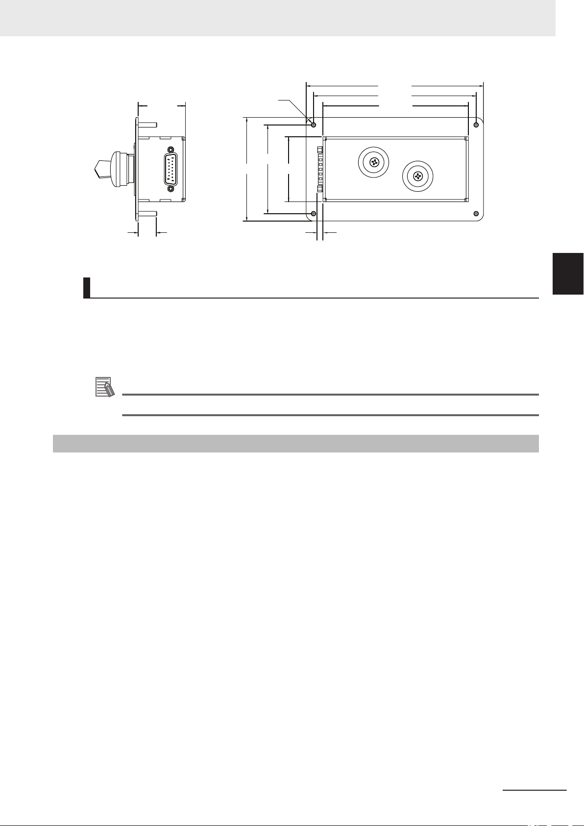
56 mm
76 mm
89 mm
125 mm
152 mm
140 mm
41 mm
16 mm
Ø 4 mm
5 mm
3 Installation
Front Panel Connections
The Front Panel is connected directly to the XFP connector on the XSYSTEM cable with the 3 m ex-
tension cable supplied with the Front Panel.
• The part number of the extension cable is 10356-10500.
• The length of the extension cable is 3 m.
3-8 Installing Safety Equipment
3
3-8-2 Safety Circuits
3-8-2
Additional Information
Refer to XFP Connections on page 3-23 for more information.
Safety Circuits
The XSYSTEM cable provides connections for all emergency stop circuits. All emergency stop circuits
are dual-channel and voltage-free. These voltage-free contacts are provided by a redundant, cyclical-
ly-checked, positive-drive, safety relay circuit for Category 3 PL-d per ISO 13849 operation.
The XUSR connector provides access to the following safety circuits.
• Dual channel emergency stop inputs.
• Dual channel emergency stop status outputs.
• Dual channel muted safety gate inputs.
• Dual channel Automatic / Manual mode status outputs.
The XFP connector provides access to the following safety circuits that are typically used with the
Front Panel.
• Dual channel emergency stop inputs.
• Dual channel Automatic / Manual mode selection inputs.
• High power indicator output.
• High power enable input.
• Control power indicator output.
The XMCP connector provides access to the following safety circuits that are use with a connected
Teach Pendant.
• Dual channel E-stop button inputs.
• Dual channel pendant enable switch inputs.
Use the diagram below to understand safety circuits.
i4L Robots User's Manual (I658)
3-21
Page 86

ES1
ES2
XFP-1
XFP-9
XMCP-1
XMCP-9
XUSR-1
XUSR-14
XUSR-3
XMCP-3
XMCP-11
XFP-2
XFP-10
XMCP-2
XMCP-10
XUSR-2
XUSR-15
XUSR-4
XUSR-17
XUSR-16
XMCP-4
XMCP-12
XUSR-18
XUSR-19
ES1
ES2
SR1 SR2
AM2 AM1
XUSR-5
XUSR-6
XFP-13
XFP-5
XFP-6
XFP-14
XSYSTEM-5
XFP-4
XFP-3
XFP-12XFP-11
XUSR-9
XUSR-10
AM2
AM1
XUSR-23
XUSR-22
XUSR-8
XUSR-7
XUSR-20
XUSR-21
AM2 AM1
XUSR-16 XUSR-17
Manual Mode
Automatic Mode
Force-Guided
Relay Cycle
Check Control
Circuit
Muted Safety
Gate
48 VDC High
Power Input
(External)
Internal High
Power
Emergency Stop
Status Outputs
Automatic Mode
Status Outputs
Automatic / Manual
Mode Selection
High Power
Indicator /
Button
PIN 1
PIN 14
PIN 13
PIN 25
3 Installation
XUSR Connections
Use the information in the following table to understand the signals provided on the XUSR connector.
Pins Description Additional Information
1, 14 Emergency stop channel 1 input Typically connected to normally closed contacts on user-
2, 15 Emergency stop channel 2 input
supplied safety devices such as E-stop buttons, safety
switches, or safety relays.
3-22
i4L Robots User's Manual (I658)
Page 87
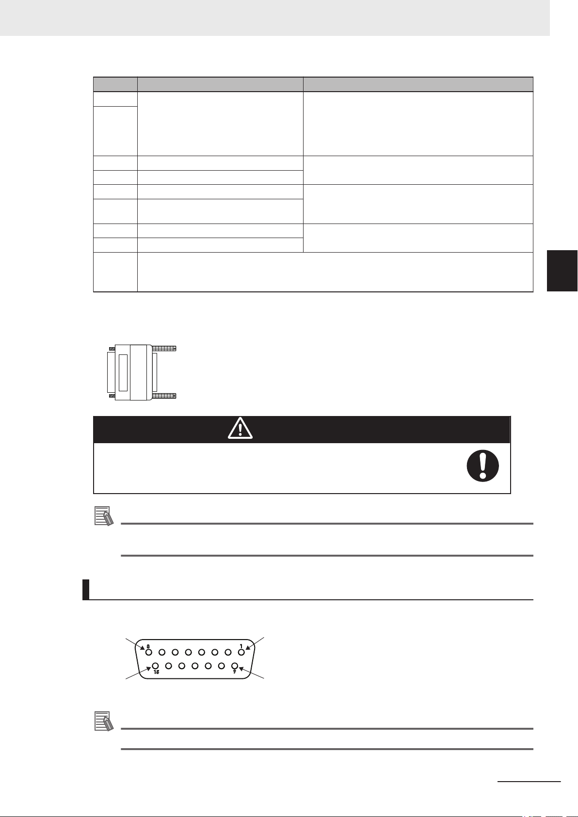
XUSR PLUG
04736-000
PIN 1
PIN 9
PIN 8
PIN 15
3 Installation
Pins Description Additional Information
3, 16 Line emergency stop inputs Normally closed contacts on user-supplied safety devices
4, 17
5, 18 Muted safety gate channel 1 input Causes emergency stop in Automatic mode only.
6, 19 Muted safety gate channel 2 input
7, 20 Emergency stop status channel 1 output Internal contacts are closed when Front Panel, Teach
8, 21 Emergency stop status channel 2 output
9, 22 Automatic mode status channel 1 Internal contacts are closed when the robot is in automat-
10, 23 Automatic mode status channel 2
11, 12,
13, 24,
25
XUSR Jumper Plug
Reserved for future use.
The XUSR jumper plug is provided for safety equipment troubleshooting only.
typically used for other robot or line emergency stop interconnection.
This does not affect emergency stop indication signals on
pins 7, 20.
Pendant, and user-supplied safety devices are not enabled / activated.
ic mode.
3-8 Installing Safety Equipment
3
3-8-2 Safety Circuits
WARNING
Never run a robot system with all jumpers installed. This would leave the system
with no E-Stops.
Additional Information
The XUSR jumper plug is supplied with the robot.
The part number for the XUSR jumper plug is 04736-000.
XFP Connections
Use the information in the following table to understand the signals provided on the XFP connector.
Additional Information
Refer to Front Panel Connections on page 3-21 for more information.
i4L Robots User's Manual (I658)
3-23
Page 88
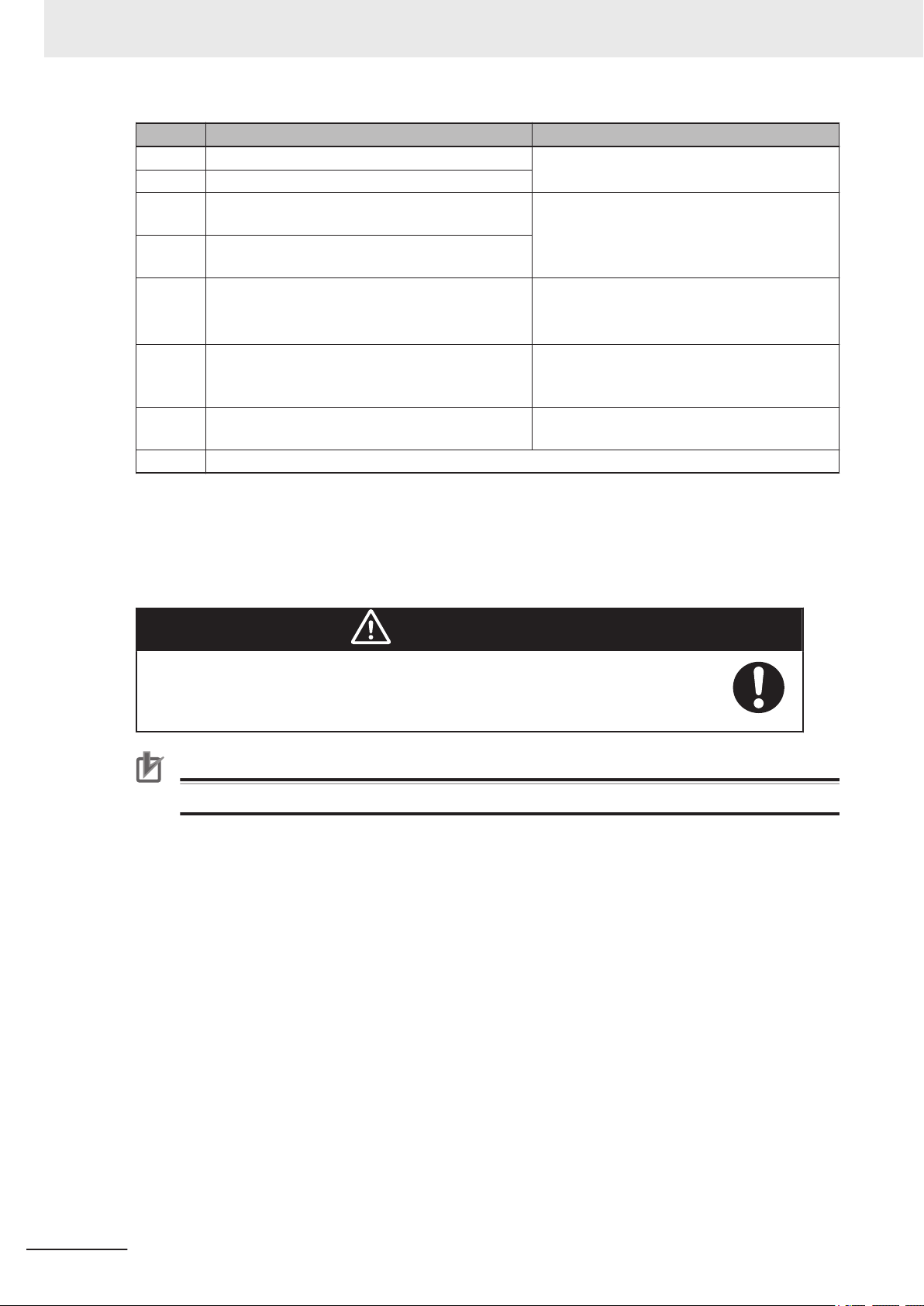
3 Installation
1, 9 Front panel E-stop button channel 1 input Typically connected to normally closed contacts
2, 10 Front panel E-stop button channel 2 input
3, 11 Automatic / Manual mode selection channel 1 in-
4, 12 Automatic / Manual mode selection channel 2 in-
5, 13 System-supplied 5 VDC output (pin 5) and com-
6, 14 High Power ON / OFF Typically connected to a momentary push-but-
7, 15 System-supplied 5 VDC output (pin 7) and com-
8 Reserved for future use
*1. Lamps that illuminate with a low current (10 mA to 25 mA) may appear dim when the High Power is OFF
Pins Description Additional Information
on the E-stop button used with the Front Panel.
Typically connected to the selector switch used
put
put
mon (pin 13) for High Power indicator lamp.
mon (pin 15) for Control Power indicator.
due to leakage current. If this occurs, add additional resistance to ensure the lamp is OFF when High Power
is not enabled.
with the front panel. An open circuit selects
Manual mode. A closed circuit selects Automatic mode.
If lamp is user-supplied, it must draw between
10 mA to 500 mA to satisfy the internal High
Power lamp monitoring function.
ton that enables High Power when all safety
circuits are satisfied.
If indicator is user-supplied, the recommended
load is between 20 to 500 mA.
*1
XFP Wiring Diagram
Use the following diagram to understand XFP electrical connections.
WARNING
If you supply your own Front Panel E-Stop, its design must comply with the requirements of IEC 60204-1 and ISO 13849. The E-Stop's push button must comply
with ISO 13850.
Precautions for Correct Use
Do not disable or bypass the High Power button. This will violate IEC 60204-1.
3-24
i4L Robots User's Manual (I658)
Page 89

+24 VDC
+5 VDC
Common
7
6
5
4
2
3
1
8
10
9
11
12
13
14
15
XFP
+24 VDC
PIN 1
+5 VDC
Common
PIN 10
PIN 9
PIN 11
PIN 12
PIN 13
PIN 14
PIN 5
PIN 4
PIN 3
Common
Control Power
Indicator
Automatic / Manual
Mode Switch
High Power
Button / Indicator
E-stop Button
XFP PLUG
10053-000
PIN 1
PIN 9
PIN 8
PIN 15
3 Installation
3-8 Installing Safety Equipment
3
3-8-2 Safety Circuits
XFP Jumper Plug
The XFP jumper plug is provided for safety equipment troubleshooting.
WARNING
Never run a robot system with all jumpers installed. This would leave the system
with no E-Stops.
Additional Information
• The XFP jumper plug is supplied with the robot.
• The part number for the XFP jumper plug is 10053-000.
XMCP Connections
Use the information in the following table to understand the signals provided on the XMCP connector.
i4L Robots User's Manual (I658)
3-25
Page 90

XMCP PLUG
10052-000
3 Installation
1, 9 Pendant E-stop button channel 1 Connected to the pendant's integrated E-stop button.
2, 10 Pendant E-stop button channel 2
3, 11 Pendant enable switch channel 1 Connected to the pendant's integrated enable switch.
4, 12 Pendant enable switch channel 2
6 24 VDC pendant supply
7 Serial communications TXD Pendant serial communications transmit signal.
8 Serial communications RXD Pendant serial communications receive signal.
13 Serial communications GND Pendant serial communications ground signal.
Shield Ground shield
5, 14, 15 Reserved for future use.
Additional Information
Refer to the T20 Pendant User's Manual (Cat. No. I601) for additional information.
Precautions for Correct Use
If Teach Pendant cabling is installed, the jumper plug or the Teach Pendant must be connected
to satisfy safety circuits and allow High Power to be enabled.
Pins Description Additional Information
XMCP Jumper Plug
The XMCP jumper plug is used when there is no T20 pendant adapter cable connected.
WARNING
Never run a robot system with all jumpers installed. This would leave the system
with no E-Stops.
Additional Information
• The XMCP jumper plug is supplied with the robot.
• The part number for the XMCP jumper plug is 10052-000.
Teach Pendant Jumper Plug
The Teach Pendant jumper plug is provided to allow the system to operate when Teach Pendant
cabling is installed, but the Teach Pendant is not connected. This plugs into the Teach Pendant
adapter cable when the pendant is not in use.
3-26
i4L Robots User's Manual (I658)
Page 91

Additional Information
• The jumper plug is supplied with the Teach Pendant kit.
• The part number for the Teach Pendant jumper plug is 10048-000.
3 Installation
3-8 Installing Safety Equipment
3
3-8-2 Safety Circuits
i4L Robots User's Manual (I658)
3-27
Page 92

High Power
Ground
Chassis
Ground
3 Installation
3-9
3-9-1
Supplying Power and Ground
The robot requires separate 24 VDC and 48 VDC power supplies. The 24 VDC supply provides Con-
trol Power and the 48 VDC supply provides power to the internal servo amplifiers.
A lockout tagout main disconnect device must be installed on the AC supply to the 24 VDC and 48
VDC power supplies. These devices are user-supplied. Disconnect devices shall be accessible and
conveniently located to facilitate application of lockout devices during service and maintenance.
Use the information below to make all power supply connections to the robot.
Additional Information
Refer to 2-3-1 Power Supply Specifications on page 2-12 for information about power supply
requirements and other wiring details.
Grounding the System
The system should be grounded properly to avoid transient voltages or other electrical noise. There
are two primary ground points on the system as described below.
• High Power ground
• Chassis ground
Precautions for Safe Use
The Joint 3 quill and the tool flange are not grounded to protective earth. If hazardous voltages
are present at any user-supplied robot-mounted equipment or tooling, you must install a ground
connection from that equipment or tooling to the ground point on the robot base.
3-28
Ground Circuit
Use the following diagram to understand the recommended grounding circuit.
i4L Robots User's Manual (I658)
Page 93

48 VDC
Power Supply
+
-
+
-
24 VDC
Power Supply
AC
Supply
Ground
Ground
L
N
L
N
Robot
Main
Disconnect
Device
+24 VDC
0 VDC
3 Installation
3-9 Supplying Power and Ground
3
3-9-2 24 VDC Connections
3-9-2
3-9-3
24 VDC Connections
The 24 VDC Control Power connector is located on the Primary Interface Panel. A 24 VDC power sup-
ply mating connector is provided with the robot.
Use the illustration below to understand the polarity of the mating connector.
Additional Information
The connector and pins are provided with the robot and require assembly with user-supplied
wires. The connector part number is 02708-000. The pin part number is 02709-000.
48 VDC Connections
The 48 VDC High Power connector is located on the Primary Interface Panel. A 48 VDC power supply
mating connector is provided with the robot.
Use the illustration below to understand the polarity and ground terminals of the mating connector.
Additional Information
The connector and pins are provided with the robot and require assembly with user-supplied
wires. The connector part number is 22009-000L. The pin part number is 02709-000.
i4L Robots User's Manual (I658)
3-29
Page 94

+48 VDC
0 VDC
GND
3 Installation
3-30
i4L Robots User's Manual (I658)
Page 95

3 Installation
3-10
3-10-1
3-10-2
Verifying Installation
If any modifications have been made to the robot during installation or other actions, make the follow-
ing checks before operation.
Mechanical Checks
Make the following mechanical checks after any hardware adjustments have been made to the sys-
tem.
• Check that the robot mounting surface is secure and adequate.
• Check all mounting bolts and other fasteners for proper torque.
• Check the tool flange and end-of-arm tooling for correct installation and grounding (when necessa-
ry).
• Check any equipment that is mounted to the robot to make sure it is securely fastened.
System Cable Checks
Make the following system cable checks after any adjustments have been made to cable connections.
• Check all cables and connectors to ensure that they are securely fastened and free of damage.
• Check the system ground and power supply connections to make sure that they are connected
properly.
• Check that all cables are adequately supported and not strained near the connectors.
3-10 Verifying Installation
3
3-10-1 Mechanical Checks
3-10-3
Safety Equipment Checks
Make the following checks to all user-supplied safety equipment to ensure emergency stops are prop-
erly installed and other safety systems are functioning correctly.
When checking safety equipment, the following prerequisites are necessary.
• ACE software must be installed and available.
• The Front Panel operating mode switch must be in the Automatic position.
• All emergency stop devices must be able to be activated and deactivated easily.
Use the following utilities in the ACE software to confirm safety operations controlled by robot soft-
ware.
Safety Setting Function Description
Configure Teach Restrict The objective of the Teach Restrict feature is to comply with safety regulations
Verify Teach Restrict Auto
Verify Teach Restrict Manual
which require that the speed be limited while the robot is in Manual mode.
This is hardware-based safety functionality to prevent rapid robot motion in
Manual mode even in the unexpected event of software error attempting to
move a robot faster than allowed. While jogging the robot in Manual mode, if
any joint exceeds its configured speed limit, the system will disable High Power.
Configuration will set predetermined speed limits for each robot motor.
Verification will verify that Teach Restrict operations are functioning properly in
Automatic and Manual modes.
i4L Robots User's Manual (I658)
3-31
Page 96

3 Installation
Configure E-stop Hardware
Delay
Verify E-stop Hardware Delay
Emergency Stop Check Procedure
Use the following procedure to check for correct emergency stop operation.
Safety Setting Function Description
The objective of the ESTOP hardware delay feature is to comply with safety
regulations which require the robot to have the capability of disabling High
Power without software intervention in an emergency stop situation.
Configuration will set the delay for the emergency stop timer circuit.
Verification will verify that High Power is disabled without software intervention in an emergency stop situation.
Additional Information
Refer to the Automation Control Environment (ACE) Version 4 User's Manual (Cat. No. I633) for
more information about using the Safety Setting functions.
1 If a pendant is present in the system, connect it to the XSYSTEM cable.
2 Prepare all emergency stop devices for enabling the robot High Power.
3 Enable the robot High Power with one of the methods described in 4-3-1 Enabling Robot High
Power on page 4-5.
Confirm that robot High Power is enabled using the High Power indicator. If robot High Power
4
is not enabled, refer to Section 5 Troubleshooting on page 5-1 for more information.
Activate each and every emergency stop device connected to the system to check that High
5
Power is disable for all safety equipment. This includes pendant safety devices, Front Panel
safety devices, and any other safety equipment wired to the XUSR connector. After one safety
device check is made, deactivate it, enable High Power again, and make a check for the next
safety device. Repeat 2 to 5 until all safety device functionality is confirmed to be working prop-
erly.
High Power Indicator Check
When High Power is enabled, an amber indicator lamp must turn ON to alert personnel that the robot
is capable of motion to satisfy safety requirements.
3-32
High Power Indicator Check Procedure
Use the following procedure to verify that the High Power indicator is working correctly.
1 Apply Control Power to the robot and disable High Power.
2 Make a High Power request using one of the methods described in High Power Request Meth-
ods on page 4-6.
i4L Robots User's Manual (I658)
Page 97

3 Installation
3 Check that the High Power indicator flashes. After the High Power request is made and the in-
dicator is checked, the procedure is complete.
3-10-4
Switch Position Checks
3-10 Verifying Installation
Switches on the Primary Interface Panel are reserved for future use and have no effect on the opera-
tion of the system.
3
3-10-4 Switch Position Checks
i4L Robots User's Manual (I658)
3-33
Page 98

3 Installation
3-34
i4L Robots User's Manual (I658)
Page 99

Operation
This section provides information necessary to operate the robot.
4
4
4-1 Payload and Acceleration Considerations ..................................................4-2
4-2 Robot Control Modes..................................................................................... 4-3
4-2-1 Manual Mode................................................................................................... 4-3
4-2-2 Automatic Mode .............................................................................................. 4-3
4-3 Enabling and Disabling the Robot................................................................ 4-5
4-3-1 Enabling Robot High Power ............................................................................ 4-5
4-3-2 Disabling High Power...................................................................................... 4-6
4-4 LED Indicator.................................................................................................. 4-7
4-5 Brake Operation .............................................................................................4-8
4-5-1 Built-in Brake Release Button ......................................................................... 4-8
4-6 Connecting to the Robot .............................................................................4-10
4-6-1 Initial Connection Procedure ......................................................................... 4-10
4-7 Manually Jogging the Robot ....................................................................... 4-11
i4L Robots User's Manual (I658)
4-1
Page 100

0
10
20
30
40
50
60
70
80
90
100
110
0
100
200
300
400
500
600
700
800
900
1000
1100
Acceleration (m/s²)
Acceleration (%)
0.3 kg
Payload Z-Location vs. Acceleration at 100% Speed
(Linear Moves Only)
0 100 200 300
400
500
Payload Z-Location (mm) = Joint 3 Position + Payload Center of Gravity
0.5 kg
1.0 kg
2.0 kg
3.0 kg
4.0 kg
5.0 kg
4 Operation
4-1
Payload and Acceleration Considerations
Careful considerations must be made when using high payloads, high accelerations, or a combination
of both.
If non-linear moves such as joint moves or arc moves are required with high speeds or high payloads,
contact your local OMRON representitive for more information about acceleration and payload limita-
tions.
Use the following chart to understand the limitations to acceleration and payload when making linear
moves. Some linear moves are not achievable over all paths in the working envelope.
Precautions for Correct Use
Operating the robot outside of the payload and speed constraints described in this document
can damage or reduce the service life of the z-axis quill.
4-2
i4L Robots User's Manual (I658)
 Loading...