

Motor Timer
pply
H2C
Please read and understand this catalog before purchasing the
products. Please consult your OMRON representative if you have any
questions or comments. Refer to Warranty and Application
Considerations (page 12), and Safety Precautions (page 10).
DIN-sized (48 x 48, 45 x 75 mm) Motor Timer
with Variable Time Ranges
• Five time ranges are selectable per timer unit.
• Easy-to-monitor neon lamp for timing operation indication (for
110, 120, 220, 240 VAC types only).
• Easy-to-set large transparent knob and easy-to-read single pattern scale facilitate time setting.
• Equipped with timing operation indicator and moving pointer.
• Conforms to EN61812-1 and IEC60664-1 4 kV/1 for Low Voltage, and EMC Directives (except for H2C-F@).
Model Number Structure
■ Model Number Legend
H2C-@ @
12
1. External Connection/Attachment
None: 11-pin socket
S: 11-pin socket/time setting ring
8: 8-pin socket
F: Front screw
Ordering Information
■ List of Models
Operation/resetting
system
Time-limit operation/
self-resetting
Time-limit operation/
electric resetting
Internal
connection
Parallel motor and
clutch connection
Separate motor
and clutch connection
8-pin socket SPDT SPDT --- H2C-8
11-pin socket H2C
Front screw --- H2C-F
8-pin socket SPDT --- --- H2C-8R
11-pin socket SPDT H2C-R
Front screw --- H2C-FR
2. Operation/Resetting System
Terminal Time-limit
contact
None: Time-limit operation/self-resetting
R: Time-limit operation/electric resetting
Instantaneous
contact
Attachment Model
Y92A-Y1 Time Setting Ring
Y92A-Y1 Time Setting Ring
H2C-S
H2C-SR
Note: Specify both the supply voltage and time range code (A, B, or C) in addition to the model number when ordering.
Example: H2C-S 24 VAC B
Time range code
voltage
Su
Motor Timer H2C 1
■ Accessories (Order Separately)
Name/specifications Models
Flush Mounting Adapter Y92F-30
Time Setting Ring (See note 1.) Y92A-Y1
Mounting Track 50 cm (l)
1 m (l)
1 m (l)
End Plate PFP-M
Spacer PFP-S
Protective Cover Y92A-48B
Track Mounting/Front Connecting
Socket
Back Connecting Socket 8-pin, screw terminal P3G-08
Hold-down Clip (See note 3.) For PL08 and PL11 Sockets Y92H-1
Note: 1. Supplied with H2C-S/-SR models.
2. Y92A-48G is a finger safe terminal cover which is attached to the P3G-08 or P3GA-11 Socket.
3. Hold-down Clips are sold in sets of two.
8-pin P2CF-08
8-pin, finger safe type P2CF-08-E
11-pin P2CF-11
11-pin, finger safe type P2CF-11-E
8-pin, finger safe type P3G-08 with Y92A-48G (See note 2.)
11-pin P3GA-11
11-pin, finger safe type P3GA-11 with Y92A-48G (See note 2.)
For PF085A Socket Y92H-2
´ 7.3 mm (t) PFP-50N
´ 7.3 mm (t) PFP-100N
´ 16 mm (t) PFP-100N2
Specifications
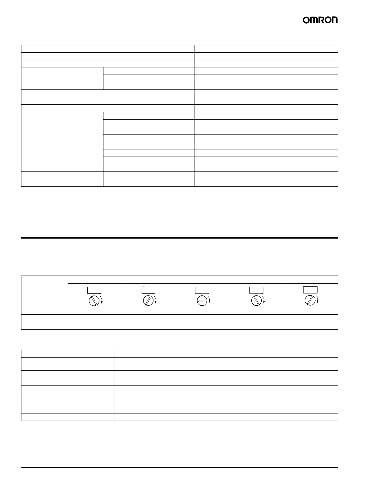
■ Time Ranges
Five time ranges are available for each timer by turning the time range selector every 60 degrees.
Note: Rated time is displayed on the window.
Time range code Position of time range selector
A 1.25 to 30 s 7.5 s to 3 min 1.25 to 30 min 7.5 min to 3 h 1.25 to 30 h
B 0.2 to 6 s 2 to 60 s 0.2 to 6 min 2 to 60 min 0.2 to 6 h
C 0.5 to 12 s 5 to 120 s 0.5 to 12 min 5 to 120 min 0.5 to 12 h
■ Ratings
Item H2C
Rated supply voltage (motor and
clutch)
Operating voltage range 85% to 110% of rated supply voltage
Power consumption 4.2 VA max. (3.96 W max.)
Reset voltage 10% max. of rated supply voltage
Reset time Minimum power-opening time: 0.5 s
Control outputs 6 A at 250 VAC, resistive load (cos
Mounting method Flush mounting (except for H2C-F/-FR models), surface mounting, DIN track mounting
Note: The front panel of the timer is color coded to identify the following supply voltage classifications:
100 to 120 V: Blue
200 to 240 V: Red
Other classes: Black
24, 48, 100, 110, 115, 120, 200, 220, or 240 VAC (50/60 Hz) (see note)
Minimum pulse width: 0.5 s
φ = 1)
2 Motor Timer H2C

■ Characteristics
)
)
Accuracy of operating time ±0.5% FS max. á±1% max. at 0.2 to 6 s for the time range code B or at 0.5 to 12 s for the time range
code C)
Setting error
±2% FS max.
Reset time 0.5 s max.
Influence of voltage
Influence of temperature
Insulation resistance 100 M
±1% FS max.
±2% FS max.
Ω min. (at 500 VDC)
Dielectric strength 2,500 VAC, 50/60 Hz for 1 min (between current-carrying and non-current-carrying parts)
2,000 VAC, 50/60 Hz for 1 min (between contact and control circuit and between contacts of different
polarities)
1,000 VAC, 50/60 Hz for 1 min (between non-continuous contacts)
Vibration resistance Destruction: 10 to 55 Hz with 0.375-mm single amplitude for 1 h each in three directions
Malfunction: 10 to 55 Hz with 0.25-mm single amplitude for 10 min each in three directions
Shock resistance
Destruction: 1,000 m/s
Malfunction: 150 m/s
2
2
Ambient temperature Operating: –10°C to 50°C
Storage: –25
°C to 65°C
Ambient humidity Operating: 45% to 85%
Life expectancy Mechanical: 10,000,000 operations min. (under no load at 1,800 operations/h)
Electrical: 500,000 operations min. (3 A at 250 VAC, resistive load at 1,800 operations/h)
See Life-test Curve for other details.
Motor life expectancy 20,000 h
Approved standards UL917, CSA C22.2 No.14.
Conforms to EN61812-1 and IEC60664-1 4 kV/1 (except for H2C-F@ models).
Output category according to EN60947-5-1 (except for H2C-F@ models).
EMC (except for H2C-F@ models) (EMI) EN61812-1
Emission Enclosure: EN55011 Group 1 class A
Emission AC Mains: EN55011 Group 1 class A
(EMS) EN61812-1
Immunity ESD: IEC61000-4-2: 6 kV contact discharge (level 3)
8 kV air discharge (level 3)
Immunity RF-interference from AM Radio Waves: IEC61000-4-3: 10 V/m (80 MHz to 1 GHz) (level 3)
Immunity Burst: IEC61000-4-4: 2 kV power-line (level 3)
2 kV I/O signal-line (level 4)
Immunity Surge: IEC61000-4-5: 1 kV line to line (level 3)
2 kV line to ground (level 3)
Case color Light gray (Munsell 5Y7/1)
Degree of protection IP40 (panel surface)
Weight H2C series: approx. 180 g
H2C-F series: approx. 270 g
■ Life-test Curve
)
300
4
200
100
50
40
30
20
10
5
1234 56
Switching operations (x 10
250 VAC cosφ = 1
24 VDC cosφ = 1
Load current (A
)
300
4
200
100
50
40
30
20
10
5
123456
Switching operations (x 10
250 VAC cosφ = 0.4
24 VDC L/R = 7 msec
Load current (A
Motor Timer H2C 3
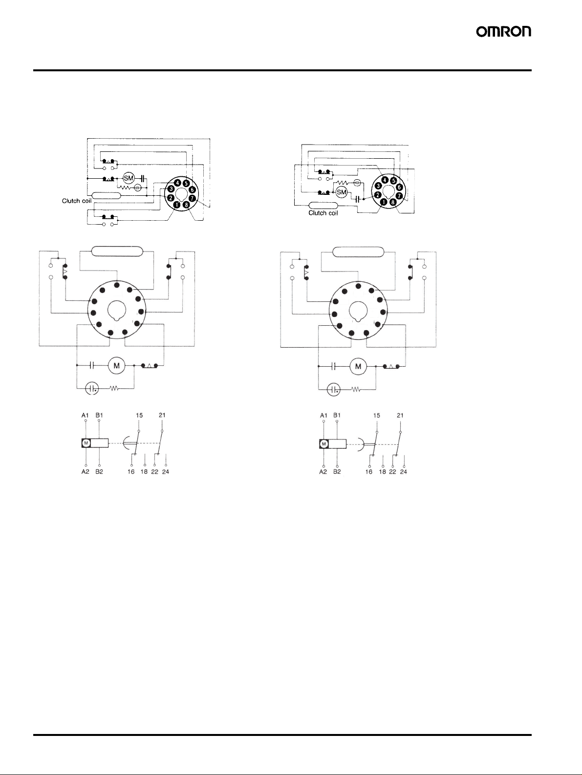
Connections
■ Terminal Arrangement
Note: The connections diagrams are for when the clutch is in the excited, reset state.
H2C-8
H2C-8R
H2C(-F)/H2C-S H2C-(F)R/H2C-SR
Clutch coil
(B2)
6
(B1)
7
5
(16)
(B2)
(22)
(B1)
(18)
(16)
4
(A1)
(18)
(A2)
3
(21)
(15)
(A1)
2
(15)
8
(24)
(22)
9
(24)
(A2)
10
(21)
11
1
5
4
(16)
(18)
3
(A1)
2
Clutch coil
6
(B2)
(B1)
(A2)
(21)
(15)
11
1
7
(22)
(24)
8
9
10
(DIN 46 199-5)
4 Motor Timer H2C
(DIN 46 199-5)
 Loading...