

Omron G9SX-AD322-T15-RT, G9SX-AD322-T150-RC, G9SX-AD322-T15-RC, G9SX-AD322-T150-RT, G9SX-ADA222-T15-RT User Manual
...
Flexible Safety Unit G9SX 1
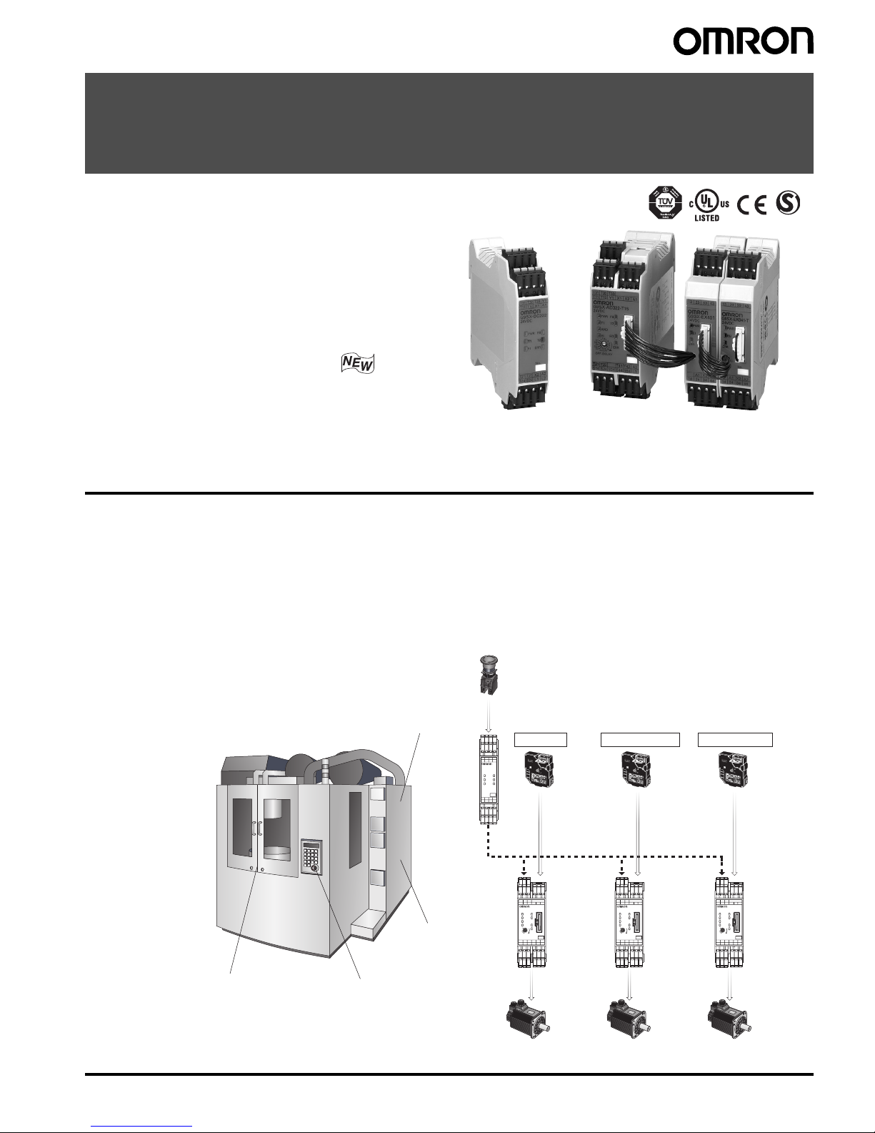
Flexible Safety Unit
G9SX
Logical AND Function Adds Flexibility
to I/O Expansion
• Facilitates partial or complete control system setup.
• Solid-state outputs (excluding Expansion Units).
• Detailed LED indications enable easy diagnosis.
• TÜV Product Service certification for compliance
with IEC/EN61508 (SIL3) and EN954-1 (Cat. 4).
• Approved by UL and CSA.
• New unit joins the Series with the following
two additional features:
-OFF-delay time of up to 150 seconds
(The OFF-delay output also complies with Cat. 4.)
-Two logical AND connection inputs
Note: Refer to Precautions on pages 17 and 18.
Features
Basic Unit
G9SX-BC
Advanced Unit
G9SX-AD
Advanced Uni
t
G9SX-AD
Advanced Unit
G9SX-AD
Tool changer door
Pallet changer door
Emergency
Stop Switch
Main door
Main Door
Pallet Changer Door
Tool Changer Door
Safety Door
Switch
Safety Door
Switch
Safety Door
Switch
Logical
connection
Emergency Stop Switch
No.
OFF-DELAY
0.5
0.4
0.3
0.2
15
10
7
5
4
3
2
1.5
1
0.6
0.7
0
S54S44S34S24S14 L1
A2T42T41T22T21
A1X2X1Y1T12T11
T33T31
T1
ERR
EI
AND
FB
ED
T2
PWR
T32
G9SX-AD322-T15
No.
OFF-DELAY
0.5
0.4
0.3
0.2
15
10
7
5
4
3
2
1.5
1
0.6
0.7
0
S54S44S34S24S14 L1
A2T42T41T22T21
A1X2X1Y1T12T11
T33T31
T1
ERR
EI
AND
FB
ED
T2
PWR
T32
G9SX-AD322-T15
No.
OFF-DELAY
0.5
0.4
0.3
0.2
15
10
7
5
4
3
2
1.5
1
0.6
0.7
0
S54S44S34S24S14 L1
A2T42T41T22T21
A1X2X1Y1T12T11
T33T31
T1
ERR
EI
AND
FB
ED
T2
PWR
T32
G9SX-AD322-T15
No.
T1 T2
FB
ERREI
PWR
L2L1S24S14
A2X2T22T21
A1X1T12T11
Y1T32 T33T31
G9SX-BC202
24VDC
● Productivity
“Partial stop” and “Complete stop” enhance productivity without sacrificing safety.
● Maintenance
LED indicators and detachable terminals for better maintenance.
● Expandability
“Logical connection” enables easier modification and expansion of machines.
Ex) Machining Center
• When the Emergency Stop Switch is pressed, the entire machine will stop.
• When a door is open, the corresponding part will not activate.
2 Flexible Safety Unit G9SX
Model Number Structure
■ Model Number Legend
1. Functions
AD/ADA: Advanced Unit
BC: Basic Unit
EX: Expansion Unit
2. Output Configuration (Instantaneous Safety Outputs)
0: None
2: 2 outputs
3: 3 outputs
4: 4 outputs
3. Output Configuration (OFF-delayed Safety Outputs)
0: None
2: 2 outputs
4: 4 outputs
4. Output Configuration (Auxiliary Outputs)
1: 1 output
2: 2 outputs
5. Max. OFF-delay Time
Advanced Unit
T15: 15 s
T150: 150 s
Basic Unit
No indicator: No OFF delay
Expansion Unit
No indicator: No OFF delay
T: OFF delay
6. Terminal Block Type
RT: Screw terminals
RC: Spring-cage terminals
Ordering Information
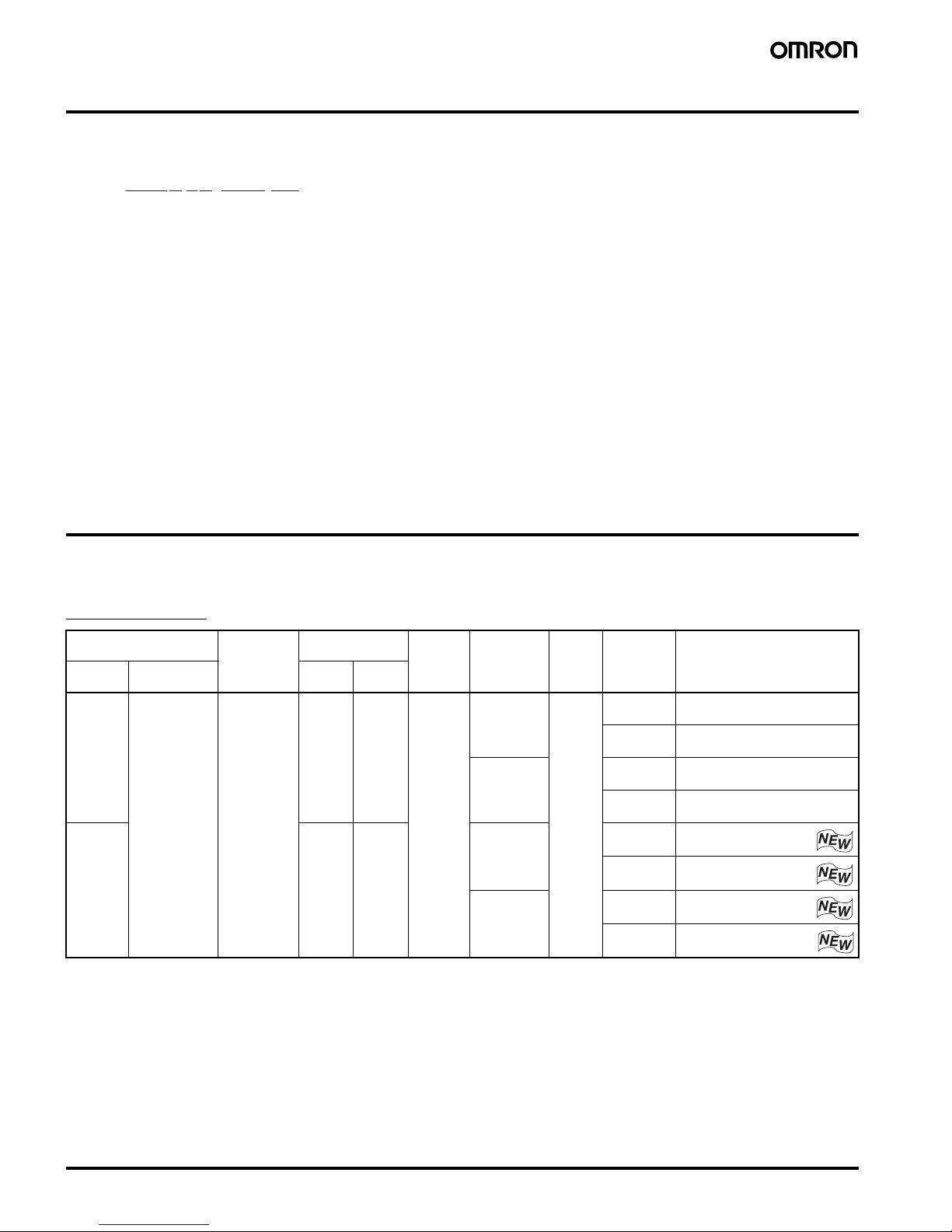
■ List of Models
Advanced Unit
Note: 1. The OFF-delay time can be set in 16 steps as follows:
T15: 0/0.2/0.3/0.4/0.5/0.6/0.7/1/1.5/2/3/4/5/7/10/15 s
T150: 0/10/20/30/40/50/60/70/80/90/100/110/120/130/140/150 s
2. The OFF-delayed output becomes an instantaneous output by setting the OFF-delay time to 0 s.
3. P channel MOS FET transistor output
4. PNP transistor output
12 5 634
G9SX-@@@@@@-@@@-@@
Safety outputs
(solid state) (See note 3.)
Auxiliary
outputs
(solid state)
(See note 4.)
Logical AND
connection
No. of
input
channels
Max. OFFdelay time
(See note 1.)
Rated
voltage
Terminal
block type
Model
Instanta-
neous
OFF-delayed
(See note 2.)
Inputs Outputs
3 2 2 1 1 1 or 2
channels
15 s 24 VDC Screw
terminals
G9SX-AD322-T15-RT
Spring-cage
terminals
G9SX-AD322-T15-RC
150 s Screw
terminals
G9SX-AD322-T150-RT
Spring-cage
terminals
G9SX-AD322-T150-RC
2 2 2 15 s Screw
terminals
G9SX-ADA222-T15-RT
Spring-cage
terminals
G9SX-ADA222-T15-RC
150 s Screw
terminals
G9SX-ADA222-T150-RT
Spring-cage
terminals
G9SX-ADA222-T150-RC
Flexible Safety Unit G9SX 3
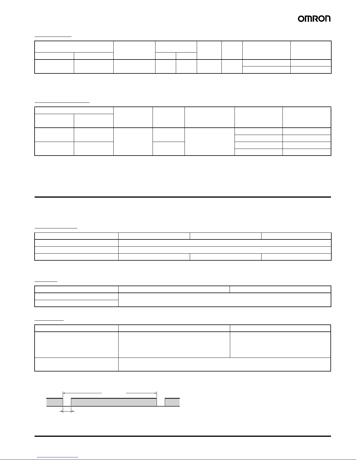
Basic Unit
Note: 1. P channel MOS FET transistor output
2. PNP transistor output
Expansion Unit
Note: 1. PNP transistor output
2. The OFF-delay time is synchronized to the OFF-delay time setting in the connected Advanced Unit (G9SX-AD-@/G9SX-ADA-@).
Specifications
■ Ratings
Power input
Note: Power consumption of loads not included.
Inputs
Outputs
Note: 1. While safety outputs are in the ON state, the following signal sequence is output continuously for diagnosis. When using the safety outputs
as input signals to control devices (i.e. Programmable Controllers), consider the OFF pulse shown below.
2. The following derating is required when Units are mounted side-by-side.
G9SX-AD322-@/G9SX-ADA222-@/G9SX-BC202-@: 0.4 A max. load current
Safety outputs
(solid state) (See note 1.)
Auxiliary outputs
(solid state)
(See note 2.)
Logical AND
connection
No. of
input
channels
Rated
voltage
Terminal block type Model
Instantaneous OFF-delayed Inputs Outputs
2 --- 2 0 2 1 or 2
channels
24 VDC Screw terminals G9SX-BC202-RT
Spring-cage terminals G9SX-BC202-RC
Safety outputs (contact) Auxiliary
outputs
(solid state)
(See note 1.)
OFF-delay
time
Rated voltage Terminal block type Model
Instantaneous OFF-delayed
4 PST-NO --- 1 --- 24 VDC Screw terminals G9SX-EX401-RT
Spring-cage terminals G9SX-EX401-RC
--- 4 PST-NO (See note 2.) Screw terminals G9SX-EX041-T-RT
Spring-cage terminals G9SX-EX041-T-RC
Item G9SX-AD322-@/ADA222-@ G9SX-BC202-@ G9SX-EX-@
Rated supply voltage 24 VDC
Operating voltage range
−15% to 10% of rated supply voltage
Rated power consumption (See note.) 4 W max. 3 W max. 2 W max.
Item G9SX-AD322-@/ADA222-@ G9SX-BC202-@
Safety input Operating voltage: 20.4 VDC to 26.4 VDC, internal impedance: approx. 2.8 k
Ω
Feedback/reset input
Item G9SX-AD322-@/ADA222-@ G9SX-BC202-@
Instantaneous safety output
OFF-delayed safety output (See note 1.)
P channel MOS FET transistor output
Load current:
Using 2 outputs or less: 1 A DC max. (See note 2.)
Using 3 outputs or more: 0.8 A DC max.
P channel MOS FET transistor output
Load current:
Using 1 output: 1 A DC max. (See note 2.)
Using 2 outputs: 0.8 A DC max.
Auxiliary output PNP transistor output
Load current: 100 mA max.
ON
OFF
360 µs max.
Approx. 100 ms
4 Flexible Safety Unit G9SX
Expansion Unit
■ Characteristics
Note: 1. When two or more Units are connected by logical AND, the operating time and response time are the sum total of the operating times
and response times, respectively, of all the Units connected by logical AND.
2. Represents the operating time when the safety input turns ON with all other conditions set.
3. Represents the operating time when the logical AND input turns ON with all other conditions set.
4. This does not include the operating time or response time of Advanced Units that are connected.
5. This does not include the operating time or response time of internal relays in the G9SX-EX-@.
6. For the G9SX-@-RT (with screw terminals) only.
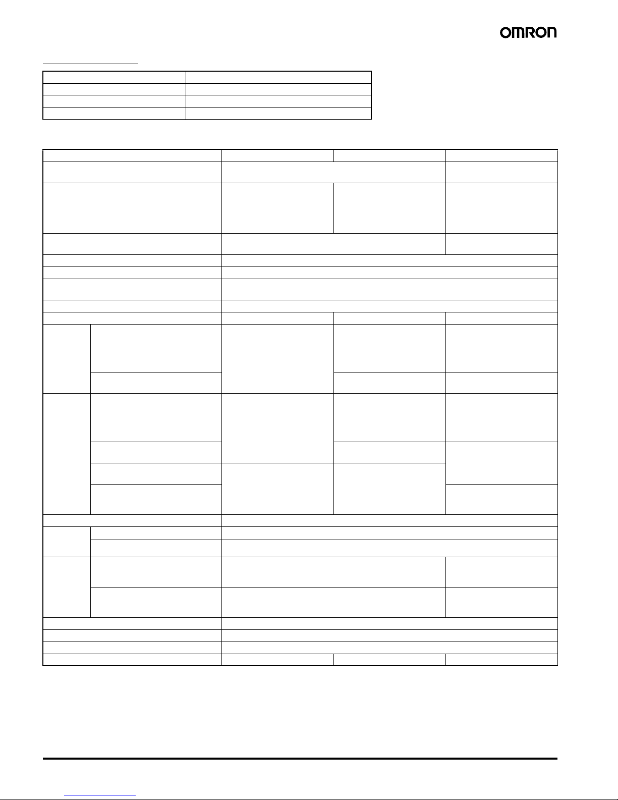
Item G9SX-EX-@
Rated load 250 VAC, 3A/30 VDC, 3A (resistive load)
Rated carry current 3 A
Maximum switching voltage 250 VAC, 125 VDC
Item G9SX-AD322-@/ADA222-@ G9SX-BC202-@ G9SX-EX-@
Over-voltage category (IEC/EN 60664-1) II II (Safety relay outputs 13 to
43 and 14 to 44: III)
Operating time (OFF to ON state)
(See note 1.)
50 ms max. (Safety input: ON)
(See note 2.)
100 ms max. (Logical AND
connection input: ON) (See
note 3.)
50 ms max. (Safety input: ON) 30 ms max. (See note 4.)
Response time (ON to OFF state)
(See note 1.)
15 ms max. 10 ms max. (See note 4.)
ON-state residual voltage 3.0 V max. (safety output, auxiliary output)
OFF-state leakage current 0.1 mA max. (safety output, auxiliary output)
Maximum wiring length of safety input and
logic AND input
100 m max.
(External connection impedance: 100
Ω max. and 10 nF max.)
Reset input time (Reset button pressing time) 100 ms min.
Accuracy of OFF-delay time (See note 5.) Within
± 5% of the set value --- Within ± 5% of the set value
Insulation
resistance
Between logical AND connection
terminals, and power supply
input terminals and other input
and output terminals connected
together
20 M
Ω min. (by 100 VDC
megger)
--- ---
Between all terminals connected
together and DIN rail
20 M
Ω min. (at 100 VDC) 100 MΩ min. (at 500 VDC)
Dielectric
strength
Between logical AND connection
terminals, and power supply
input terminals and other input
and output terminals connected
together
500 VAC for 1 min --- ---
Between all terminals connected
together and DIN rail
500 VAC for 1 min 1,200 VAC for 1 min
Between different poles of
outputs
--- ---
Between safety relay outputs
connected together and other
terminals connected together
2,200 VAC for 1 min
Vibration resistance Frequency: 10 to 55 to 10 Hz, 0.375-mm single amplitude (0.75-mm double amplitude)
Mechanical
shock
resistance
Destruction
300 m/s
2
Malfunction
100 m/s
2
Durability Electrical --- 100,000 cycles min.
(rated load, switching
frequency: 1,800 cycles/hour)
Mechanical --- 5,000,000 cycles min.
(switching frequency: 7,200
cycles/hour)
Ambient temperature
−10 to 55°C (no icing or condensation)
Ambient humidity 25% to 85%
Terminal tightening torque (See note 6.) 0.5 N·m
Weight Approx. 200 g Approx. 125 g Approx. 165 g

Flexible Safety Unit G9SX 5
Logical AND Connection
Note: 1. See Logical AND Connection Combinations below for details.
2. The number of G9SX-EX401-@ Expansion Units or G9SX-EX041-T-@ Expansion Units (OFF-delayed Model) not included.
3. G9SX-EX401-@ Expansion Units and G9SX-EX041-T-@ Expansion Units (OFF-delayed Model) can be mixed.
Logical AND Connection Combinations
1. One logical AND connection output from an Advanced Unit
G9SX-AD can be logical AND connected to up to four Advanced
Units.
2. Two logical AND outputs from a Basic Unit G9SX-BC can be
logical AND connected to up to eight Advanced Units.
3. Two logical AND outputs from an Advanced Unit G9SX-ADA can
be logical AND connected to up to eight Advanced Units.
4. Any Advanced Unit with logical AND input can be logical AND
connected to Advanced Units on up to five tiers.
5. Two logical AND connection outputs, each from different
Advanced/Basic Units, can be logical AND connected to
a single G9SX-ADA Unit.
6. The largest possible system configuration contains a total of 20
Advanced and Basic Units. In this configuration, each Advanced
Unit can have up to five Expansion Units.
Item G9SX-AD322-@/ADA222-@ G9SX-BC202-@ G9SX-EX-@
Number of Units connected per
logical AND output
4 Units max. ---
Total number of Units connected
by logical AND (See note 2.)
20 Units max. ---
Number of Units connected in
series by logical AND
5 Units max. ---
Max. number of Expansion Units
connected (See note 3.)
--- 5 Units
Maximum cable length for logical
AND input
100 m ---
G9SX-AD
G9SX-ADG9SX-ADG9SX-ADG9SX-AD
G9SX-BC
G9SX-AD
G9SX-ADG9SX-ADG9SX-ADG9SX-AD
G9SX-AD G9SX-AD G9SX-AD
G9SX-AD
G9SX-ADG9SX-ADG9SX-ADG9SX-AD
G9SX-ADA
G9SX-AD G9SX-AD G9SX-AD
G9SX-BC or
G9SX-AD or
G9SX-ADA
G9SX-AD
G9SX-AD
G9SX-AD
G9SX-AD
G9SX-BC G9SX-BC
G9SX-ADA
Number of Units connected
per logical AND output:
4 Units max.
Total number of Units
connected by logical AND:
20 Units max.
Number of Units connected
in series by logical AND:
5 Units max.
Note 1: Basic Unit = G9SX-BC
Advanced Unit = G9SX-AD or G9SX-ADA
Note 2: The G9SX-AD322-T-@ has only one logical AND
output.
Advanced Unit
or Basic Unit
Advanced UnitAdvanced Unit Advanced Unit
Advanced Unit
Advanced Unit Advanced Unit Advanced Unit
Advanced Unit
Advanced Unit Advanced Unit Advanced Unit
Advanced Unit Advanced Unit Advanced Unit
Advanced Unit
Advanced Unit Advanced Unit Advanced Unit
Advanced Unit
6 Flexible Safety Unit G9SX
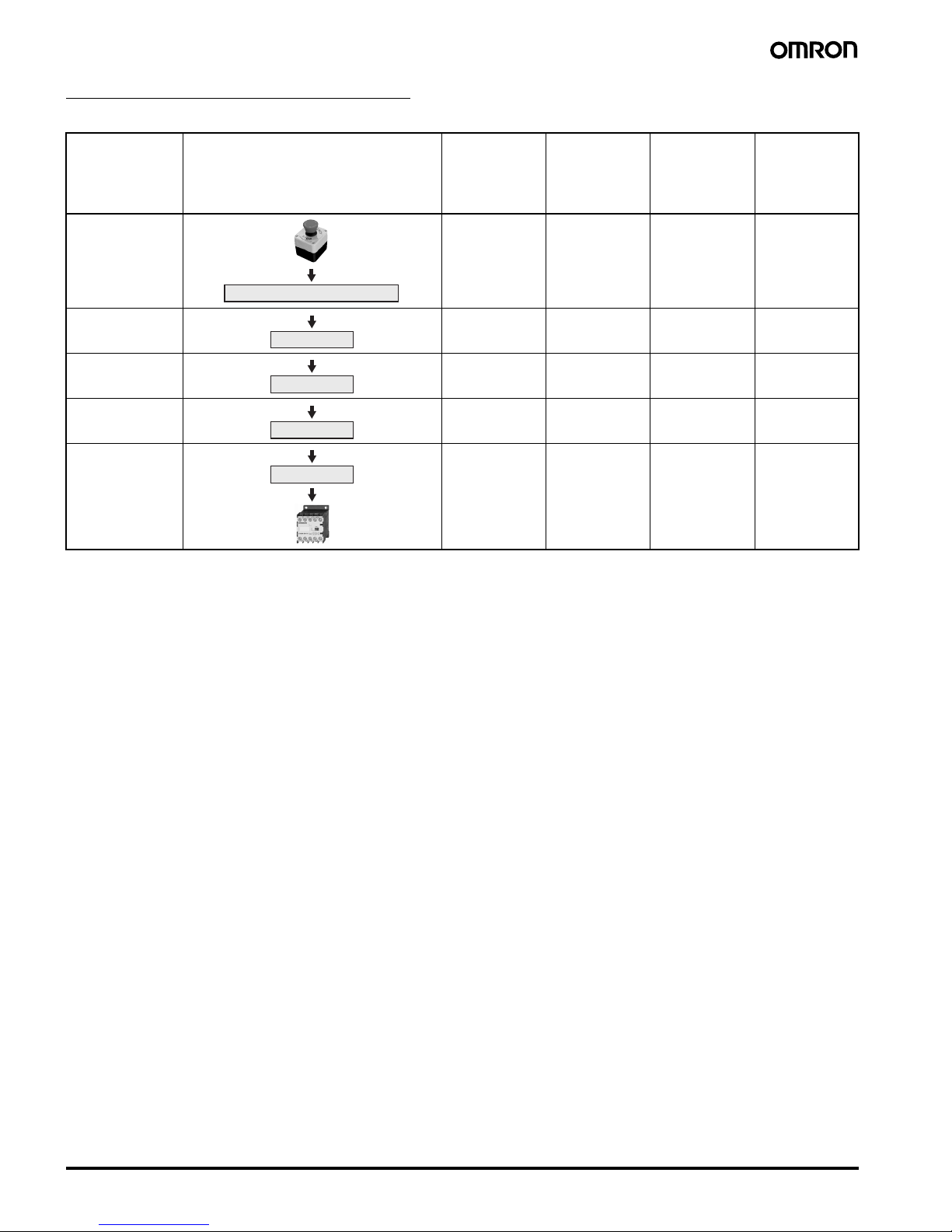
Response Time and Operating Time
The following table shows the response time for two or more Units that are logical AND connected.
Note: 1. The maximum response time (not including Expansion Units) in this block flow diagram is the time it takes the output from the Unit on the
lowest tier to switch from ON to OFF after the input to the Unit on the highest tier switches from ON to OFF.
2. The maximum response time (including Expansion Units) in this block flow diagram is the time it takes the output from the Expansion Unit
connected to the Unit on the lowest tier to switch from ON to OFF after the input to the Unit on the highest tier switches from ON to OFF.
3. The maximum operating time (not including Expansion Units) in this block flow diagram is the time it takes the output from the Unit on
the lowest tier to switch from OFF to ON after the input to the Unit on the highest tier switches from OFF to ON.
4. The maximum operating time (including Expansion Units) in this block flow diagram is the time it takes the output from the Expansion
Unit connected to the Unit on the lowest tier to switch from OFF to ON after the input to the Unit on the highest tier switches from OFF to
ON.
Item Block flow diagram Max. response
time (not
including
Expansion
Units)
(See note 1.)
Max. response
time (including
Expansion
Units)
(See note 2.)
Max. operating
time (not
including
Expansion
Units)
(See note 3.)
Max. operating
time (including
Expansion
Units)
(See note 4.)
Tier
First tier 15 ms 25 ms 50 ms 80 ms
Second tier 30 ms 40 ms 150 ms 180 ms
Third tier 45 ms 55 ms 250 ms 280 ms
Fourth tier 60 ms 70 ms 350 ms 380 ms
Fifth tier 75 ms 85 ms 450 ms 480 ms
Advanced Unit or Basic Unit
Advanced Unit
Advanced Unit
Advanced Unit
Advanced Unit
Flexible Safety Unit G9SX 7
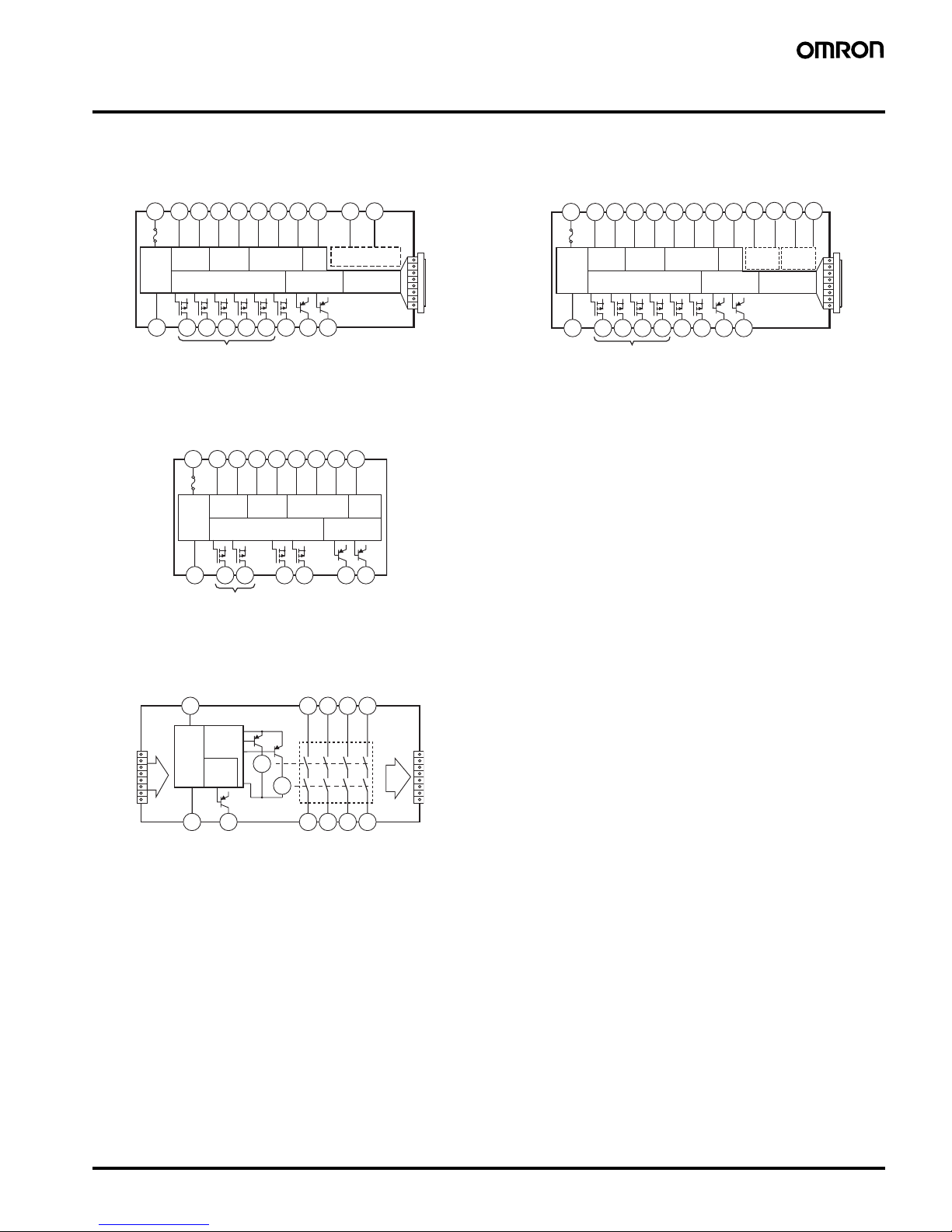
Connections
■ Internal Connection
G9SX-AD322-@ (Advanced Unit)
Note: 1. Internal power supply circuit is not isolated.
2. Logical AND input is isolated.
3. Outputs S14 to S54 are internally redundant.
G9SX-BC202-@ (Basic Unit)
Note: 1. Internal power supply circuit is not isolated.
2. Outputs S14 and S24 are internally redundant.
G9SX-EX401-@/G9SX-EX041-T-@ (Expansion
Unit / Expansion Unit OFF-delayed model)
Note: 1. Internal power supply circuit is not isolated.
2. Relay outputs are isolated.
G9SX-ADA222-@ (Advanced Unit)
Note: 1. Internal power supply circuit is not isolated.
2. Logical AND inputs are isolated.
3. Outputs S14 to S54 are internally redundant.
(See
note 1.)
(See note 2.)
S14A2S24 S34 S44 S54
L1 X1 X2
Power
supply
circuit
Safety
Input 1
Safety
Input 2
Reset/Feedback
Input
Cross
fault
detection
input
Safety output control
Auxiliary
output control
Logical AND input
Expansion Unit
output control
T11A1 T12 T21 T22 T31 T32 T33 Y1 T41 T42
(
See note 3.
)
(See
note 1.)
Reset/Feedback
Input
Cross
fault
detection
input
S14A2S24 L1 L2
X1 X2
Power
supply
circuit
Safety
Input 1
Safety
Input 2
Safety outputs control
Auxiliary
outputs control
T11A1T12 T21 T22 T31 T32 T33
Y1
(
See note 2.
)
A2 X2
Power
supply
circuit
Auxiliary
output
control
Safety
output
control
A1
K1
13 23 33 43
14 24 34 44
K2
Exp.
sig.
IN
Exp.
sig.
OUT
(See
note 1.)
(See note 2.)
(See
note 1.)
(See
note
2.)
S14A2S24 S44 S54
L1 L2 X1 X2
Power
supply
circuit
Safety
Input 1
Safety
Input 2
Reset/Feedback
Input
Cross
fault
detection
input
Safety output control
Auxiliary
output control
Logical
AND input
Expansion Unit
output control
T11A1 T12 T21 T22 T31 T32 T33 Y1
T41 T42
(See note 3.)
T51 T52
Logical
AND input 2
8 Flexible Safety Unit G9SX
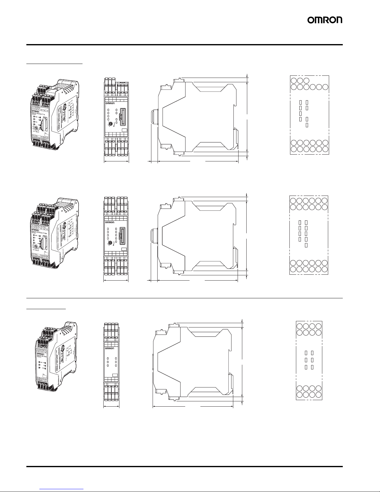
Dimensions
Note: All units are in millimeters unless otherwise indicated.
Advanced Unit
Basic Unit
No.
OFF-DELAY
0.5
0.4
0.3
0.2
15
10
7
5
4
3
2
1.5
1
0.6
0.7
0
S54S44S34S24S14 L1
A2T42T41T22T21
A1X2X1Y1T12T11
T33T31
T1
ERR
EI
AND
FB
ED
T2
PWR
T32
G9SX-AD322-T15
24VDC
(10)
115 max.
100 max.
35.5 max.
(35)*
(6) (See note 2.)
(6) (See note 2.)
* T
yp
ical dimension
FBPWR
T1
AND
EIT2ED
ERR
S44
T41
S14
T21
S24
T22
S34 S54
T42L1A2
T33T32T31
X1Y1
T12T11
X2 A1
Terminal arrangement
Note: 1. Above outline drawing is for -RC terminal type.
2. For -RC terminal type only.
G9SX-AD322-@
FBPWR
T1
AND1
EIT2ED
ERR
AND2
S54
T41
S14
T21
S24
T22
S44
L1
T42
L2
A2
T33T32T31
X1Y1
T12T11
X2 A1
Terminal arrangement
T52T51
(10)
115 max.
100 max.
(6) (See note 2.)
(6) (See note 2.)
* T
yp
ical dimension
No.
OFF-DELAY
0.5
0.4
0.3
0.2
15
10
7
5
4
3
2
1.5
1
0.6
0.7
0
L1S54S44S24S14 L2
A2T42T41T22T21
A1X2X1Y1T12T11
T33T31
T1
ERR
EI
AND1
FB
ED
T2
PWR
T32 T52T51
G9SX-ADA222-T150
24VDC
AND2
35.5 max.
(35)*
A
N
D
1
A
N
D
2
G9SX-ADA222-T150
Note: 1. Above outline drawing is for -RC terminal type.
2. For -RC terminal type only.
G9SX-ADA222-@
No.
T1 T2
FB
ERREI
PWR
L2L1S24S14
A2X2T22T21
A1X1T12T11
Y1T32 T33T31
G9SX-BC202
24VDC
23 max.
(22.5)*
* T
yp
ical dimension
115 max.
100 max.
(6) (See note 2.)
(6) (See note 2.)
FBPWR
T1
EI
T2
ERR
L2
A2
S14
T21
S24
T22L1X2
Y1
T33T32T31
A1X1
T12T11
Terminal arrangement
Note: 1. Above outline drawing is for -RC terminal type.
2. For -RC terminal type only.
G9SX-BC202-@
Flexible Safety Unit G9SX 9
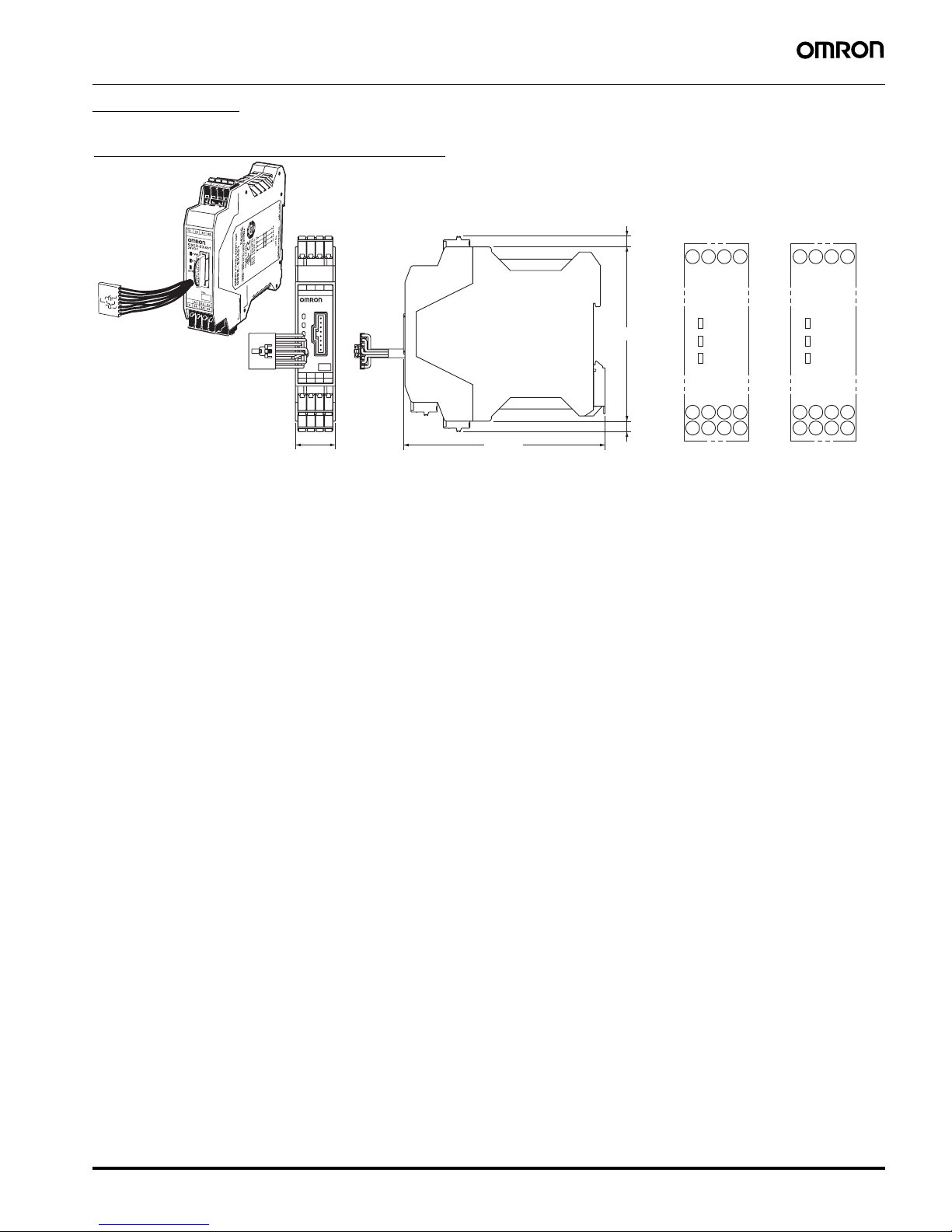
Expansion Unit
43332313
44342414
A2X2A1
G9SX-EX401
24VDC
23 max.
(22.5)*
* Typical dimension
115 max.
100 max.
(6) (See note 2.)
(6) (See note 2.
)
43332313
PWR
44
A2
14 24A134
X2
EI
ERR
43332313
PWR
44
A2
14 24A134
X2
ED
ERR
G9SX-EX041-T-@
(Expansion Unit
with OFF Delay)
G9SX-EX401-@
(Expansion Unit)
Terminal arrangement
Note: 1. Above outline drawing is for -RC terminal type.
2. For -RC terminal type only.
G9SX-EX401-@
Expansion Unit (OFF-delayed Model)
G9SX-EX041-T-@
 Loading...