

Page 1
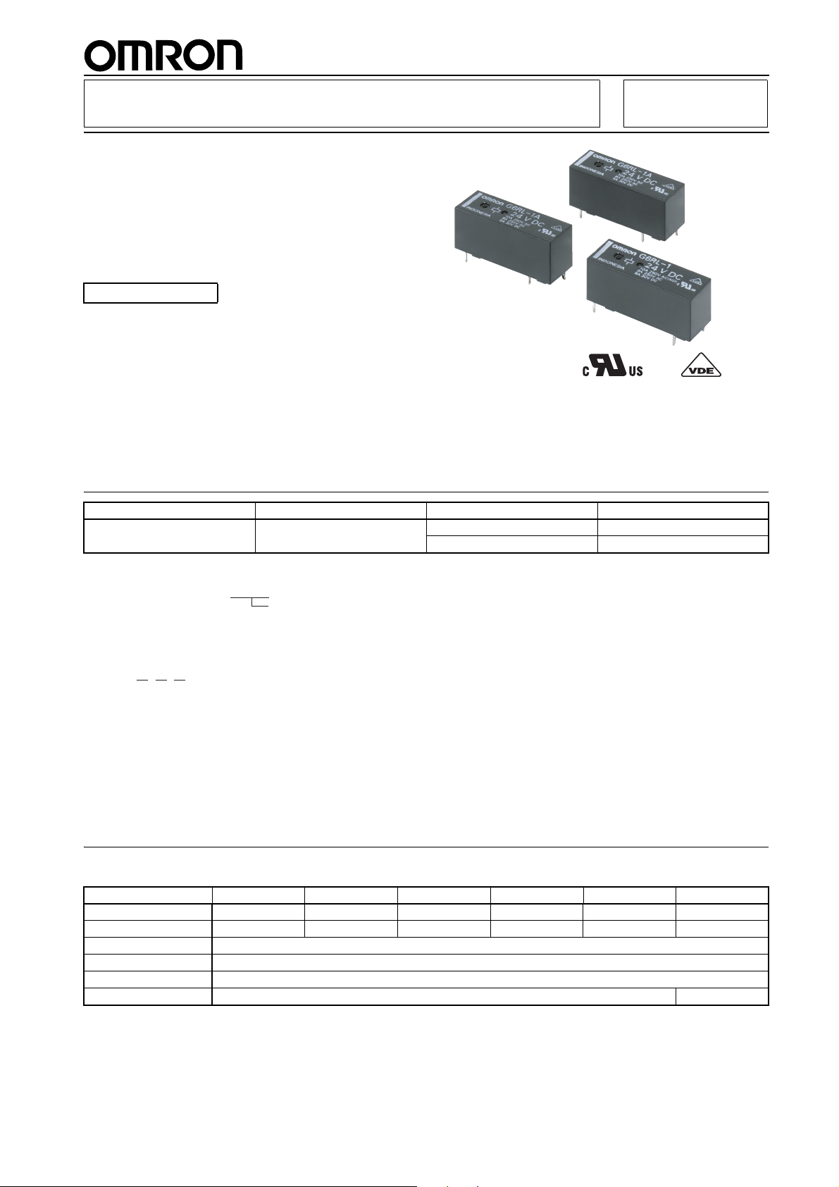
PCB Relay
g
Low-profile power relay with maximum
switching of 10 A
■ Low profile: 12.3 mm in height
■ Max. switching capacity: 2,500 VA (NO)
■ Dielectric strength: 5 kV
■ Clearance and creepage distance: 10 mm.
RoHS Compliant
Applications:
Boilers, PLCs, I/O ports, timers, and temperature controllers
Ordering Information
Classification Enclosure rating Contact form Model
Standard Flux protection SPST-NO G6RL-1A
SPDT G6RL-1
G6RL
Note: When ordering, add the rated coil voltage to the model number.
Examples: G6RL-1A 12 VDC
■
Model Number Legend:
Rated coil volta
e
G6RL-@ @ @VDC
123
1. Number of Poles
1: 1 pole
2. Contact Form/Contact Construction
None: SPDT
A: SPST-NO
3. Rated Coil Voltage
3, 5, 6, 12, 24, 48 VDC
Specifications
■ Coil Ratings
Rated voltage 3 VDC 5 VDC 6 VDC 12 VDC 24 VDC 48 VDC
Rated current 73.3 mA 44.0 mA 36.7 mA 18.3 mA 9.2 mA 5.0 mA
Coil resistance 40.9 Ω 113.6 Ω 163.6 Ω 654.5 Ω 2,618 Ω 9,600 Ω
Must operate voltage 70% max. of rated voltage
Must release voltage 10% min. of rated voltage
Max. voltage 150% of rated voltage
Power consumption Approx. 220 mW Approx. 240 mW
Note: 1. The above items are measured at a coil temperature of 23°C.
2. The tolerance of the rated current is ±10%.
1
Page 2
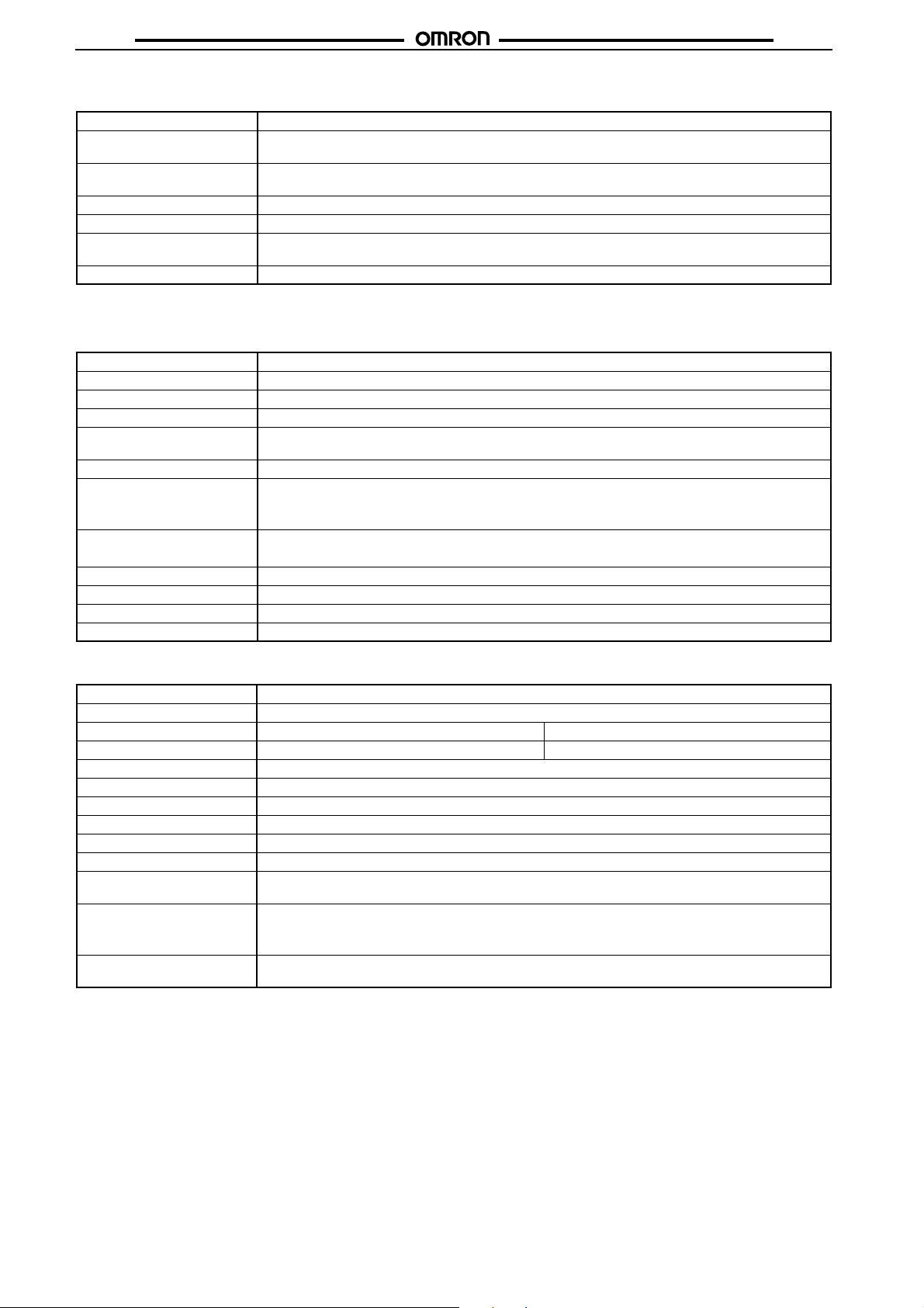
■ Contact Ratings
Load Resistive load (cos φ = 1)
Rated load 8 A at 250 VAC, resistive load
Rated carry current 10 A at 250 VAC
Max. switching voltage 400 VAC, 300 VDC
Max. switching current NO: 10 A, NC: 8 A
Max. switching power NO: 2,500 VA, NC: 2,000 VA
Failure rate (reference value) 10 mA at 5 VDC (P Level)
Note: P level: λ 60 = 0.1 × 10⁻⁶ / operations
Characteristics
■
Contact resistance 100 mΩ max.
Operate time 10 ms max.
Release time 5 ms max.
Insulation resistance 1,000 MΩ min. (at 500 VDC)
Dielectric strength 5,000 VAC, 50/60 Hz for 1 min between coil and contacts
Impulse withstand voltage 10 kV between coil and contacts (1.2 × 50 µs)
Vibration resistance Destruction: 10 to 55 to 10 Hz, 1.5-mm double amplitude
Shock resistance Destruction: 1,000 m/s
Endurance (Mechanical) 10,000,000 operations min. (at 18,000 operations/h)
Ambient temperature Operating: −40°C to 85°C (with no icing)
Ambient humidity Operating: 5% to 85%
Weight Approx. 7.8 g
5 A at 24 VDC, resistive load
5 A at 30 VDC
150 W
1,000 VAC, 50/60 Hz for 1 min between contacts of same polarity
Malfunction: 10 to 55 to 10 Hz, 0.825-mm single amplitude (1.65-mm double amplitude) when energized.
10 to 55 to 10 Hz, 0.4-mm single amplitude (0.8-mm double amplitude) when not energized.
2
Malfunction: 200 m/s2 NO, 50 m/s2 NC when not energized
G6RLG6RL
■ Other data
Insulation material group IIIa
Rated insulation voltage 250 V
Pollution degree 32
Rated voltage system 250 V 400 V
Over-voltage category III
Contact material AgNi
Creepage distance 10 mm
Clearance distance 10 mm
RoHS Compliant
Tracking index of relay base PTI 250
Flammability class according to UL94
Flammability-flame
GWFI (IEC 60695-2-12)
GWIT (IEC 60695-2-13)
Ball pressure test (IEC
60695-10-2)
V-0
850°C
750°C
170°C
2
Page 3

G6RLG6RL
■ Approved Standards
UL 508 (File No. E41643)
Model Contact form Coil rating Contact rating
G6RL-1A SPST-NO 3 to 48 VDC 10 A at 250 VAC (NO)
8 A at 250 VAC
5 A at 30 VDC
G6RL-1 SPDT
VDE (EN61810-1) (Reg. No. C266)
Model Contact form Coil rating Contact rating
G6RL-1A SPST-NO 3, 5, 6, 12, 24, or 48 VDC 10 A at 250 VAC (NO) 10,000 operations at 85°C
G6RL-1 SPDT 8 A at 250 VAC 30,000 operations at 85°C
5 A at 30 VDC 50,000 operations at 85°C
6,000 operations
VDE (60947-5-1) (Reg. No. C266)
Type Contact rating
Utilization category Rated voltage
G6RL-1(-1A) AC-15 240 VAC
DC-13 125 VDC
Electrical Endurance Data
G6RL-1(A) 8 A at 250 VAC (cosφ = 1) N.O. 50,000 operations min.
8 A at 250 VAC (cosφ = 1) N.C. 50,000 operations min.
5 A at 24 VDC C.O. 50,000 operations min.
5 A at 24 VDC N.O. 50,000 operations min.
Note: The results shown reflect values measured using very severe test conditions, i.e., Duty: 3 s ON/OFF for AC loads and 1 s ON/OFF
for DC loads.
Electrical endurance depends on the test conditions. Consult your OMRON representative for more detailed information on the electrical endurance under your test conditions.
3
Page 4

Dimensions
Note: All units are in millimeters unless otherwise indicated.
G6RL-1A
28.5 max.
10.0 max.
Terminal Arrangement/
Internal Connections
(Bottom View)
(2.9)
Mounting Holes
(Bottom View)
18.9±0.1
G6RLG6RL
5±0.1
(1.7)
0.4
0.24
0.8
0.4
0.8
3.2
12.3 max.
Five, 1.3±0.1 dia.
Note: Indicates average dimensions.
7.62±0.1
G6RL-1
Terminal Arrangement/
Internal Connections
(Bottom View)
28.5 max.
0.4
0.4
0.24
0.8
0.4
10.0 max.
3.2
0.8
12.3 max.
(1.5)
Five, 1.3±0.1 dia.
Note: Indicates average dimensions.
Mounting Holes
(Bottom View)
18.9±0.1 3.2±0.1
3.2±0.1
(1.7)
7.62±0.1
Precautions
Disclaimer:
All technical performance data applies to the product as such; specific conditions of individual applications are not considered. Always
check the suitability of the product for your intended purpose. OMRON does not assume any responsibility or liability for noncompliance
herein, and we recommend prior technical clarification for applications where requirements, loading, or ambient conditions differ from
those applying to general electric applications. Any responsibility for the application of the product remains with the customer alone. THIS
COMPONENT CAN NOT BE USED FOR AUTOMOTIVE APPLICATIONS.
ALL DIMENSIONS SHOWN ARE IN MILLIMETERS.
To convert millimeters into inches, multiply by 0.03937. To convert grams into ounces, multiply by 0.03527.
Cat. No. K133-E1-01
In the interest of product improvement, specifications are subject to change without notice.
OMRON RELAY & DEVICES Corporation
Power Relay Division
Marketing Department
1110, Sugi, Yamaga-city, Kumamoto-Pref., 861-0596 Japan
Tel: (81)968-44-4160/Fax: (81)968-44-4107
Printed in Japan
????-? (????) (?)
 Loading...