

Page 1
DeviceNet Communications Unit
E5ZN-DRT
Streamlined Communications from
Temperature Controller to PLC
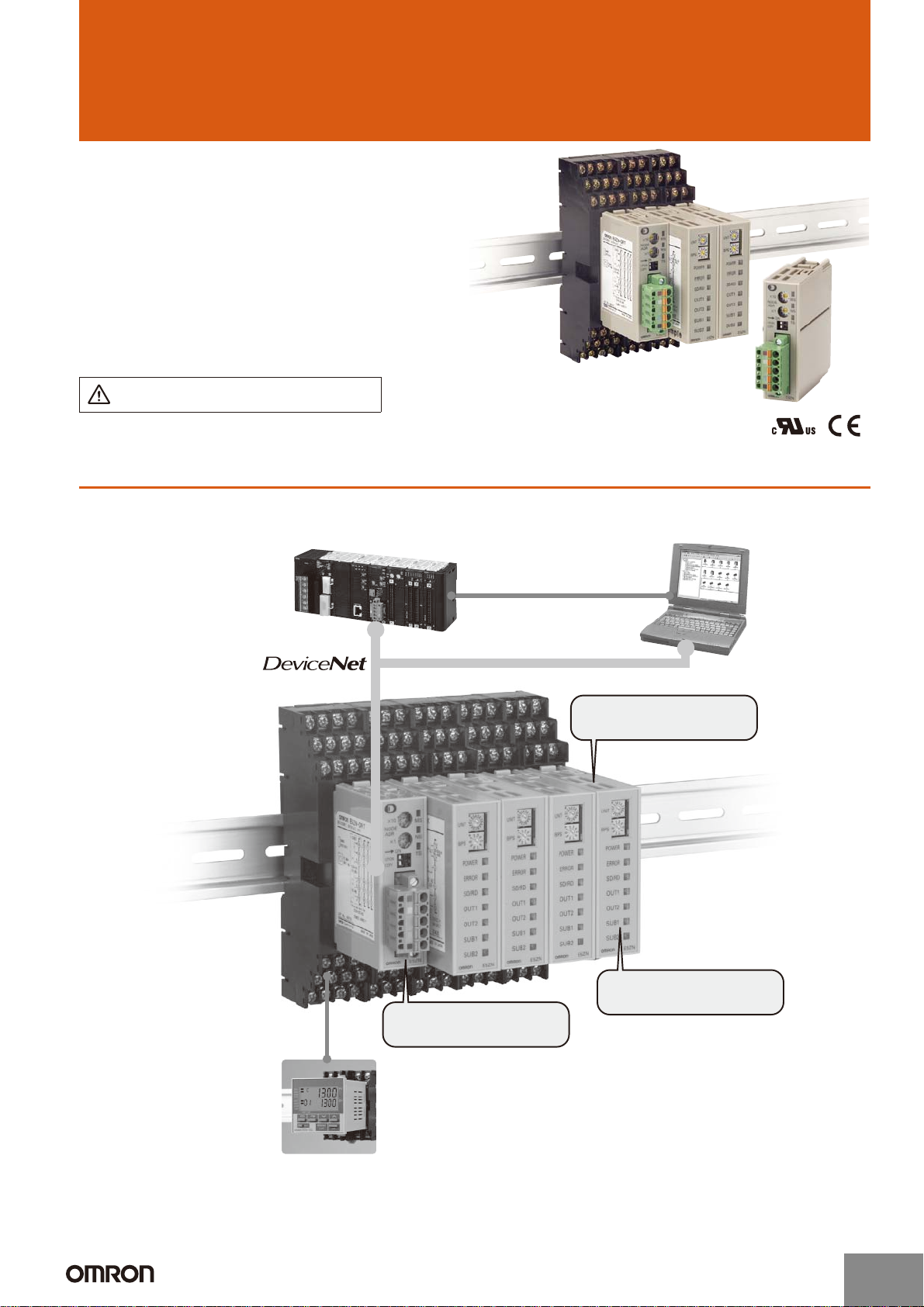
• The E5ZN Modular Temperature Controller is connected to
the DeviceNet network.
• The I/O link function allows setting and monitoring (e.g., of
present values) for the E5ZN Modular Temperature Controller to
be performed without communications programming.
• Up to 16 E5ZN Modular Temperature Controllers can be connected to one Unit.
• All the parameters for the E5ZN can be uploaded or downloaded in one operation using DeviceNet Configurator.
Refer to Safety Precautions for All
Temperature Controllers.
Features
DeviceNet Communications Unit Enables Program-free Communications with Temperature
Controllers
DeviceNet
Master
DeviceNet
Configurator
Connect up to 16 E5ZN.
http://www.ia.omron.com/
DeviceNet Communications Unit
E5ZN-DRT
Setting Display Unit
E5ZN-SDL
Operational performance equivalent to
E5CN Digital Temperature Controllers.
(c)Copyright OMRON Corporation 2007 All Rights Reserved.
Modular Temperature Controller
E5ZN
1
Page 2
E5ZN-DRT
Features
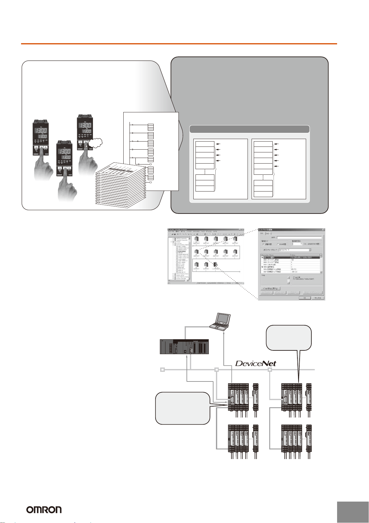
Startup Time Is Six Times Faster and No Communications Programs Are Needed
Previously, a time-consuming process of creating
communications programs, debugging, and checking
operations was required for the Temperature Controller to
communicate with the PLC.
● For example, setting 10 Units required 60 minutes.
● Incorrect inputs were a concern.
● Separate debugging for each Unit was needed.
No-protocol Example
Trigger
Trigger
Send Ready Flag
NG
Beep
Beep
Beep
Trigger
Receive Completion Flag
Receive Completion Flag
Receive Completion Flag
D'f
ASC ← Converts SP data into ASCII.
DM000
K
Sd
FSC
← Calculates FSC.
C
S
Sf
← Sends command.TDX
S
C
N
← Receives response.RXD
D
C
N
← Checks end code.
CMP
De
#3030
Normal completion
← Checks FCS.
FCS
C
D
D'f
CMP
Df
D'f
FCS check OK
DeviceNet Communications Units enable high-speed data
communications by allocating settings and monitoring
parameters in the PLCs I/O Memory Area, contributing to greater
reductions in the time required for communications program
development.
● For example, set 10 Units in 10 minutes.
● Batch download using the personal computer.
● Debugging is easy using the personal computer.
OUT Area IN Area
Wd 0 and 1
Wd 2 and 3
Wd 4 and 5
Wd 6 to 37
Wd 38
User-specified
allocations
are possible.
Wd 98
Wd 99
Wd 100
Manage All E5ZN Together from the DeviceNet Configurator
Use the DeviceNet Configurator for E5ZN
initial settings and temperature control wiring
to enable immediate execution.
PLC Memory
OUT enabled
Control ON/OFF
AT executing
Set value (SV)
Wd 0 and 1
Wd 2 and 3
Wd 4 and 5
Wd 6 and 7
Wd 8 to 37
Wd 38
Wd 98
Wd 99
Wd 100
Comm status
Control ON/OFF
AT executing
Alarm output
Process value (PV)
User-specified
allocations
are possible.
Improved Maintenance with Monitoring, Comment, and Copying Functions
● Measure the heater control time (RUN
time monitor) to manage heater life
expectancy.
● Monitor supply voltages, such as those
for Temperature Controller and
Communications Unit power supplies,
and network power supplies.
● User-specified names can be set for
each heater and Communications Unit,
enabling the location of errors to be
checked quickly.
● Upload/download Temperature Controller
parameters to the Communications Unit.
This shortens the time required to
replace Temperature Controllers.
Check the settings
for the heater of
oven No. 3.
DeviceNet
Configurator
DeviceNet
Master
Control data
Maintenance data
UNIT
UNIT
UNIT
BPS
BPS
BPS
POWER
POWER
POWER
ERROR
ERROR
ERROR
SD/RD
SD/RD
SD/RD
OUT1
OUT1
OUT1
OUT2
OUT2
OUT2
SUB1
SUB1
SUB1
SUB2
SUB2
SUB2
E5ZN
E5ZN
E5ZN
E5ZN
UNIT
UNIT
UNIT
UNIT
BPS
BPS
BPS
BPS
POWER
POWER
POWER
POWER
ERROR
ERROR
ERROR
ERROR
SD/RD
SD/RD
SD/RD
SD/RD
OUT1
OUT1
OUT1
OUT1
E5ZN-SCT24S
OUT2
OUT2
OUT2
OUT2
SUB1
SUB1
SUB1
SUB1
SUB2
SUB2
SUB2
SUB2
E5ZN
E5ZN
E5ZN
E5ZN
UNIT
BPS
POWER
ERROR
SD/RD
OUT1
OUT2
SUB1
SUB2
E5ZN
UNIT
BPS
POWER
ERROR
SD/RD
OUT1
OUT2
SUB1
SUB2
E5ZN
Check the actual
operating time
of the heater.
UNIT
UNIT
UNIT
BPS
BPS
BPS
POWER
POWER
POWER
ERROR
ERROR
ERROR
SD/RD
SD/RD
SD/RD
OUT1
OUT1
OUT1
OUT2
OUT2
OUT2
SUB1
SUB1
SUB1
SUB2
SUB2
SUB2
E5ZN
E5ZN
E5ZN
E5ZN
UNIT
UNIT
UNIT
UNIT
BPS
BPS
BPS
BPS
POWER
POWER
POWER
POWER
ERROR
ERROR
ERROR
ERROR
SD/RD
SD/RD
SD/RD
SD/RD
OUT1
OUT1
OUT1
OUT1
E5ZN-SCT24S
OUT2
OUT2
OUT2
OUT2
SUB1
SUB1
SUB1
SUB1
SUB2
SUB2
SUB2
SUB2
E5ZN
E5ZN
E5ZN
E5ZN
UNIT
BPS
POWER
ERROR
SD/RD
OUT1
OUT2
SUB1
SUB2
E5ZN
UNIT
BPS
POWER
ERROR
SD/RD
OUT1
OUT2
SUB1
SUB2
E5ZN
http://www.ia.omron.com/
(c)Copyright OMRON Corporation 2007 All Rights Reserved.
2
Page 3
Model Number Structure
■ Model Number Legend
E5ZN-DRT
E5ZN-DRT
1
1.
DRT: DeviceNet communications
Ordering Information
■ List of Models
Name External input power
DeviceNet Communications Unit 24 VDC E5ZN E5ZN-DRT
Te r m i n a l U n i t E5ZN-SCT24S
Note: A DeviceNet Communications Unit and Terminal Unit are required to connect to DeviceNet. Two End Plates are provided with E5ZN-SCT24S
Terminal Units. When mounting to a DIN track, be sure to mount End Plates on both sides.
supply voltage
Applicable Temperature
Controller
Model
Specifications
■ Ratings
Power supply voltage DeviceNet 24 VDC (for internal circuits)
External input power supply 24 VDC (for RS-485 communications circuits and Temperature Controllers)
Allowable voltage range DeviceNet 11 to 25 VDC
External input power supply 20.4 to 26.4 VDC
Power consumption
(See note 2.)
Connectable Temperature Controllers E5ZN Series
Maximum number of connectable Temperature Controllers 16
Ambient operating temperature −10 to 55°C (with no icing or condensation)
Ambient operating humidity 25% to 85%
Ambient storage temperature −25 to 65°C (with no icing or condensation)
Note: 1. Do not use an inverter output as the power supply. (Refer to Safety Precautions for All Temperature Controllers.)
2. The power consumption for the Temperature Controllers is not included.
DeviceNet Approx. 1.1 W (for a current of 45 mA at 24 VDC)
External input power supply Approx. 0.5 W (for a current of 20 mA at 24 VDC)
http://www.ia.omron.com/
(c)Copyright OMRON Corporation 2007 All Rights Reserved.
3
Page 4

E5ZN-DRT
■ Characteristics
Insulation resistance 20 MΩ min. (at 100 VDC)
Dielectric strength 500 VAC, 50/60 Hz for 1 min between the DIN track and all DeviceNet connector terminals and between the DIN track
Vibration resistance
Shock resistance
Weight 100 g max.
Safety standards cULus508
■ Communications (for Temperature Controller Expansion)
and all terminal socket terminals
2
10 to 55 Hz, 10 m/s
2
150 m/s
, 3 times each in ±X, ±Y, and ±Z directions
for 2 hrs each in ±X, ±Y, and ±Z directions
EMS: Electrostatic Discharge (ESD) EN61006-2, EN61000-4-2 (4 kV/contact, 8 kV/air)
Radiated Electromagnetic Fields EN61006-2, EN61000-4-3 (10 V/m)
Electrical Fast transients/BURST EN61006-2, EN61000-4-4 (2 kV/DC power-line, 1 kV/Signal-line)
Surge Transients EN61006-2, EN61000-4-5 (line to ground : 1 kV/DC power-line)
: 2 kV/Signal-line
line to line : 0.5 kV/DC power-line)
Conducted Disturbances EN61006-2, EN61000-4-6 (10 V)
EMI: Radiated Emissions (electric field) EN50081-2 Class A
Transmission line
RS-485 multipoint
connection method
Communications method RS-485 (2-wire, half-duplex)
Synchronization
Start-stop synchronization
method
Baud rate 38,400 bps
Transmission code ASCII
Data bit length 7 bits
Stop bit length 2 bits
Error detection Vertical parity (even)
BCC (block check character)
Flow control None
Number of Units that can
16 Units max. (32 channels)
be connected in parallel
Connections
■ Terminal Arrangement
E5ZN-DRT E5ZN-SCT24S
×10
Color
Red
Communications power, positive (+V)
Communications signal, high (CAN H)
White
---
Shield
Blue
Communications signal, low (CAN L)
Black
Communications power, negative (–V)
Signal
NODE
ADR
×1
UP/DN
COPY
MS
NS
ON
TS
External input power
supply (24VDC)
Setting Display Unit
communications
Communications for
Temperature
Controller expansion
(TOP VIEW)
+
−
B (+)
A (−)
B (+)
A (−)
19
13
20 14
21 15
22 16 10
23 17 11
24 18 12
71
82
93
4
5
6
http://www.ia.omron.com/
Not used with the DeviceNet
Communications Unit
(c)Copyright OMRON Corporation 2007 All Rights Reserved.
4
Page 5

Nomenclature
E5ZN-DRT
E5ZN-DRT
Front Panel Rotary Switches
Used to set the node address when
functioning as a DeviceNet slave.
Front Panel DIP Switch
Used to copy (backup) parameters between
×10
NODE
ADR
×1
UP/DN
COPY
ON
the Temperature Controllers and DeviceNet.
UP/DN (Pin 2): Sets the copy operationmode
(i.e., upload or download).
COPY (Pin 1): Starts the copying.
DeviceNet Connector
Connects to DeviceNet communications
cables. Power for DeviceNet communications is also supplied though this
connector. An FCK2.5/5-STF-5.08AU
connector (Phoenix Contact) is
provided.
Dimensions
Note: All units are in millimeters unless otherwise indicated.
E5ZN-DRT
MS
NS
TS
D
C
E
B
F
A
0
9
1
8
2
7
3
6
4
5
Indicators
Dimensions when Mounted to the
E5ZN-SCT24S Terminal Unit
Back Panel DIP Switch
Used to specify whether the connection
configuration and I/O allocation is set
using simple I/O allocation or Configurator
I/O allocation.
Pin 1: I/O allocation setting switch
Pin 2: Not used (Set to OFF.)
Back Panel Rotary Switch
Used to set the maximum unit number
when simple I/O allocation is used.
Terminal Unit Connector
Connects to the E5ZN-SCT24S
Terminal Unit.
130
4.7
30
72.8
27
35
46
89.6
(107.5)
Note: Be sure to read the precautions for correct use and other precautions in the following user’s manuals before using the
Communications Unit.
E5ZN-DRT DeviceNet Communications Unit Operation Manual (Cat. No. H119)
DeviceNet Operation Manual (Cat. No. W267)
ALL DIMENSIONS SHOWN ARE IN MILLIMETERS.
To convert millimeters into inches, multiply by 0.03937. To convert grams into ounces, multiply by 0.03527.
In the interest of product improvement, specifications are subject to change without notice.
http://www.ia.omron.com/
(c)Copyright OMRON Corporation 2007 All Rights Reserved.
5
Page 6

Safety Precautions for All Temperature Controllers
Refer to the precautions of individual product for more specific details.
Warning
The following products contain lithium batteries. Do not
disassemble, deform under pressure, heat to over
100°C, or incinerate these products. The lithium battery may ignite or explode. Applicable models: E5ZE,
E5LD, and E5LC.
Caution
Do not touch any of the terminals while the power is
being supplied. Doing so may result in electric shock.
Do not allow pieces of metal or wire cuttings to get
inside the Temperature Controller. Doing so may
result in electric shock, fire, or malfunction.
Do not attempt to disassemble, repair, or modify the
Temperature Controller. Any attempt to do so may
result in electric shock, fire, or malfunction.
Do not use the Temperature Controller in locations
subject to flammable or explosive gases. Doing so
may result in an explosion.
The switching capacity and switching conditions will
significantly affect the longevity of the output relays.
Use the Temperature Controller within the rated load,
and do not use the Temperature Controller beyond the
number of operations specified under electrical life.
Using the Temperature Controller beyond its electrical
life may result in contact welding or burning.
Use Temperature Controller settings that are
appropriate for the controlled system. Failure to do so
may cause unexpected operation resulting in damage
to equipment or personal injury
Prepare a circuit with an overheating prevention alarm
and implement other safety measures to ensure safe
operation in the event of a malfunction. Loss of
operational control due to malfunction may result in a
serious accident.
Tighten the terminal screws to the following
torque:
M3.5 screws: 0.74 to 0.90 N·m
M3 screws: 0.40 to 0.56 N·m
E5GN: Terminals 1 to 6: 0.23 to 0.25 N·m
Terminals 7 to 9: 0.12 to 0.14 N·m
Failure to tighten terminal screws to the correct torque
may result in fire or malfunction.
Make sure there will be no adverse affects from the
device connected to the Temperature Controller
before using the hardware test mode. Devices
connected to the Temperature Controller may reach a
dangerous state during the test.
1. Do not use the Temperature Controller in the following locations:
2. Use and store the Temperature Controller within the rated
3. Allow enough space around the Temperature Controller to
4. Be sure to wire properly with correct polarity of terminals.
5. To wire the E5AN, E5EN, or E5CN using crimp terminals, use
6. When wiring the E5GN, use a cable gauge of AWG24
7. After wiring is completed, do not pull on or bend a terminal
8. Do not connect anything to unused terminals.
9. Make sure that the power supply voltages and loads are
10. To avoid inductive noise, keep the wiring for the Temperature
11. Make sure that the rated voltage is attained within two sec-
12. Allow at least 30 seconds for the Temperature Controller to
13. When using self-tuning, turn ON power for the load (e.g.,
Operating Environment Precautions
• Locations exposed to radiated heat from heating devices
• Locations subject to exposure to water or oil
• Locations subject to direct sunlight
• Locations subject to dust or corrosive gases (in particular,
sulfide gas and ammonia gas)
• Locations subject to severe changes in temperature
• Locations subject to icing or condensation
• Locations subject to excessive shock or vibration
temperature or humidity range specified for each model.
When two or more Temperature Controllers are mounted horizontally close to each other or vertically next to one another,
the internal temperature will increase due to the heat they
radiate and the service life of the products will decrease. In
such cases, forced cooling by fans or other means of air ventilation will be required to cool down the Temperature Controllers.
ensure proper heat dissipation. Do no block the ventilating
holes.
crimp terminals designed for M3.5 screws and with a width of
7.2 mm max.
7.2 mm max.
2
(0.205 mm
use a cable gauge of AWG28 (0.081 mm
(0.326 mm
ing part to be inserted into terminals must be 5 to 6 mm.
block lead wire with a force of 30 N or higher.
within specification and rating ranges before using the Temperature Controller.
Controller's terminal board away from power cables carrying
high voltages or large currents. Also, do not wire power lines
together with or parallel to Temperature Controller wiring.
Using shielded cables to separate pipes and ducts is recommended.
Attach surge absorbers or noise filters to peripheral devices
that generate noise (e.g., motors, transformers, solenoids,
magnetic coils, or other equipment that has an inductance
element). If using a noise filter with the power supply, be sure
to confirm the voltage and the current, and then mount the
power supply as near as possible to the Temperature Controller.
Set up the Temperature Controller, along with its power supply, as far away as possible from devices that generate
strong, high-frequency waves, such as high-frequency welders and high-frequency machines, and from devices that generate surges.
onds of turning the power ON.
warm up.
heater) at the same time as or before supplying power to the
Temperature Controller. If power is turned ON for the Temperature Controller before turning ON power for the load,
self-tuning will not be performed properly and optimum control will not be achieved.
) to AWG14 (2.081 mm2) for terminals 1 to 6, and
2
) for terminals 7 to 9. The exposed current-carry-
2
) to AWG22
http://www.ia.omron.com/
(c)Copyright OMRON Corporation 2007 All Rights Reserved.
C-1
Page 7

14. In order that power can be turned OFF in an emergency by
the person operating the Temperature Controller, install the
appropriate switches and circuit breakers, and label them
accordingly.
15. Turn OFF the power before drawing out the Temperature
Controller body. Do not touch or apply excessive force to the
terminals or electronic parts. When inserting the body, make
sure that electronic parts do not come in contact with the
case.
16. When the terminal block for the E5GN is detached, do not
touch or apply excessive force to any electronic parts.
17. Use alcohol to clean the Temperature Controller. Do not use
thinner or other solvent-based substances.
18. Inverters with an output frequency of 50/60 Hz are available,
but they may cause the internal temperature of Temperature
Controller to rise, possibly resulting in smoke or burning. Do
not use an inverter output to supply power to a Temperature
Controller.
Precautions for Correct Use
● Service Life
1. Use the Temperature Controller within the specified temperature
and humidity ranges. If the product is installed inside a control
panel, the temperature around the Temperature Controller and
not the temperature around the control panel must be kept within
the specified temperature range.
2. The service life of electronic devices such as Temperature
Controllers is determined not only by the number of switching
operations performed by the relay, but also by the service life
of the internal electronic components. The service life of
these components depends on the ambient temperature: it
will be shorter if the ambient temperature is high and longer if
the ambient temperature is low. For this reason, the service
life of the product can be extended by keeping the internal
temperature of the Temperature Controller low.
3. If several Temperature Controllers are mounted side-by-side
or are arranged vertically, the heat generated by them may
cause the internal temperature of the products to rise, thus
reducing their service life. To prevent this, take steps to
ensure that the Temperature Controllers are cooled, such as
installing fans. When providing forced cooling, however, be
careful not to cool down the terminal sections alone to avoid
measurement errors.
● Measurement Accuracy
1. When extending the lead wires for thermocouples, use a compensating conductor appropriate for the type of thermocouple
use.
2. When extending the lead wires for platinum resistance thermometers, use lead wires with low resistance, and make the
resistance in the 3 lead wires equal.
3. The type of Temperature Sensor and the input type for the
Temperature Controller must be set the same.
4. There are two types of platinum resistance thermometers: Pt
and JPt. Accurate measurement will not be possible if the
input type for the Temperature Sensor is not set correctly.
5. Mount the Temperature Controller horizontally.
6. If significant errors occur, check to see if the input shift has
been set correctly.
● Waterproofing
Sections without any specification on their degree of protection or
those with IP@0 specifications are not waterproof.
● EN/IEC Compliance
Installing the following fuse in the power supply terminal block is recommended if the Temperature Controller is used in applications
requiring EN/IEC compliance.
Recommended fuse: A T2A, 250-VAC, time lag fuse with low breaking capacity
● Operating Precautions
1. It takes approximately five seconds for the outputs to turn ON
from the moment the power is turned ON. Due consideration
must be given to this time when incorporating Temperature Controllers in a sequence circuit.
2. When using the self-tuning capability of the E5@N, E5@ K, or
E5@J, supply power to the load (e.g., heater) at the same
time as or before supplying power to the Temperature Controller. If power is turned ON for the Temperature Controller
before turning ON power for the load, self-tuning will not be
performed properly and optimum control will not be achieved.
When starting operation after the Temperature Controller has
warmed up, turn OFF the power and then turn it ON again at
the same time as turning ON power for the load. (Instead of
turning the Temperature Controller OFF and ON again,
switching from STOP mode to RUN mode can also be used in
this case.)
3. The reception of the Temperature Controller may be affected
if it is used close to radios, television sets or wireless
devices.
http://www.ia.omron.com/
(c)Copyright OMRON Corporation 2007 All Rights Reserved.
C-2
Page 8

Parameter Displays
The following displays are use to represent the characters for parameter names on the Temperature Controller.
● Seven-segment Digital DIsplay
ABCDEFGH I JK LMNOPQRSTUVWXY Z
● Eleven-segment Digital Display
ab cd e fgh ijk lm nopq rstuvw xyz
ABCDEFGH I JKLMNOPQRSTUVWXYZ
ALL DIMENSIONS SHOWN ARE IN MILLIMETERS.
To convert millimeters into inches, multiply by 0.03937. To convert grams into ounces, multiply by 0.03527.
In the interest of product improvement, specifications are subject to change without notice.
http://www.ia.omron.com/
(c)Copyright OMRON Corporation 2007 All Rights Reserved.
C-3
Page 9

Read and Understand This Catalog
Please read and understand this catalog before purchasing the products. Please consult your OMRON representative if you have any questions or
comments.
Warranty and Limitations of Liability
WARRANTY
OMRON's exclusive warranty is that the products are free from defects in materials and workmanship for a period of one year (or other period if
specifi ed) from date of sale by OMRON.
OMRON MAKES NO WARRANTY OR REPRESENTATION, EXPRESS OR IMPLIED, REGARDING NON-INFRINGEMENT, MERCHANTABILITY, OR
FITNESS FOR PARTICULAR PURPOSE OF THE PRODUCTS. ANY BUYER OR USER ACKNOWLEDGES THAT THE BUYER OR USER ALONE
HAS DETERMINED THAT THE PRODUCTS WILL SUITABLY MEET THE REQUIREMENTS OF THEIR INTENDED USE. OMRON DISCLAIMS ALL
OTHER WARRANTIES, EXPRESS OR IMPLIED.
LIMITATIONS OF LIABILITY
OMRON SHALL NOT BE RESPONSIBLE FOR SPECIAL, INDIRECT, OR CONSEQUENTIAL DAMAGES, LOSS OF PROFITS, OR COMMERCIAL
LOSS IN ANY WAY CONNECTED WITH THE PRODUCTS, WHETHER SUCH CLAIM IS BASED ON CONTRACT, WARRANTY, NEGLIGENCE, OR
STRICT LIABILITY.
In no event shall responsibility of OMRON for any act exceed the individual price of the product on which liability is asserted.
IN NO EVENT SHALL OMRON BE RESPONSIBLE FOR WARRANTY, REPAIR, OR OTHER CLAIMS REGARDING THE PRODUCTS UNLESS
OMRON'S ANALYSIS CONFIRMS THAT THE PRODUCTS WERE PROPERLY HANDLED, STORED, INSTALLED, AND MAINTAINED AND NOT
SUBJECT TO CONTAMINATION, ABUSE, MISUSE, OR INAPPROPRIATE MODIFICATION OR REPAIR.
Application Considerations
SUITABILITY FOR USE
OMRON shall not be responsible for conformity with any standards, codes, or regulations that apply to the combination of products in the customer's
application or use of the product.
At the customer's request, OMRON will provide applicable third party certifi cation documents identifying ratings and limitations of use that apply to the
products. This information by itself is not suffi cient for a complete determination of the suitability of the products in combination with the end product,
machine, system, or other application or use.
The following are some examples of applications for which particular attention must be given. This is not intended to be an exhaustive list of all possible
uses of the products, nor is it intended to imply that the uses listed may be suitable for the products:
• Outdoor use, uses involving potential chemical contamination or electrical interference, or conditions or uses not described in this catalog.
• Nuclear energy control systems, combustion systems, railroad systems, aviation systems, medical equipment, amusement machines, vehicles, safety
equipment, and installations subject to separate industry or government regulations.
• Systems, machines, and equipment that could present a risk to life or property.
Please know and observe all prohibitions of use applicable to the products.
NEVER USE THE PRODUCTS FOR AN APPLICATION INVOLVING SERIOUS RISK TO LIFE OR PROPERTY WITHOUT ENSURING THAT THE
SYSTEM AS A WHOLE HAS BEEN DESIGNED TO ADDRESS THE RISKS, AND THAT THE OMRON PRODUCT IS PROPERLY RATED AND
INSTALLED FOR THE INTENDED USE WITHIN THE OVERALL EQUIPMENT OR SYSTEM.
Disclaimers
CHANGE IN SPECIFICATIONS
Product specifi cations and accessories may be changed at any time based on improvements and other reasons.
It is our practice to change model numbers when published ratings or features are changed, or when signifi cant construction changes are made.
However, some specifi cations of the product may be changed without any notice. When in doubt, special model numbers may be assigned to fi x
or establish key specifi cations for your application on your request. Please consult with your OMRON representative at any time to confi rm actual
specifi cations of purchased product.
DIMENSIONS AND WEIGHTS
Dimensions and weights are nominal and are not to be used for manufacturing purposes, even when tolerances are shown.
ERRORS AND OMISSIONS
The information in this catalog has been carefully checked and is believed to be accurate; however, no responsibility is assumed for clerical,
typographical, or proofreading errors, or omissions.
PERFORMANCE DATA
Performance data given in this catalog is provided as a guide for the user in determining suitability and does not constitute a warranty. It may represent
the result of OMRON’s test conditions, and the users must correlate it to actual application requirements. Actual performance is subject to the OMRON
Warranty and Limitations of Liability.
PROGRAMMABLE PRODUCTS
OMRON shall not be responsible for the user's programming of a programmable product, or any consequence thereof.
COPYRIGHT AND COPY PERMISSION
This catalog shall not be copied for sales or promotions without permission.
This catalog is protected by copyright and is intended solely for use in conjunction with the product. Please notify us before copying or reproducing this
catalog in any manner, for any other purpose. If copying or transmitting this catalog to another, please copy or transmit it in its entirety.
OMRON Corporation
Industrial Automation Company
http://www.ia.omron.com/
In the interest of product improvement, specifications are subject to change without notice.
(c)Copyright OMRON Corporation 2007 All Rights Reserved.
2007.7
 Loading...