

Omron E5ZE-8AQHD1TCB-V2, E5ZE-8ACAD1PB-V2, E5ZE-8AQHD1PB-V2, E5ZE-8ACAD1TCB-V2, E5ZE-8VQHD1TCB-V2 Datasheet
...Page 1
Multipoint Temperature Controller E5ZE-8@D1@B-V2 1
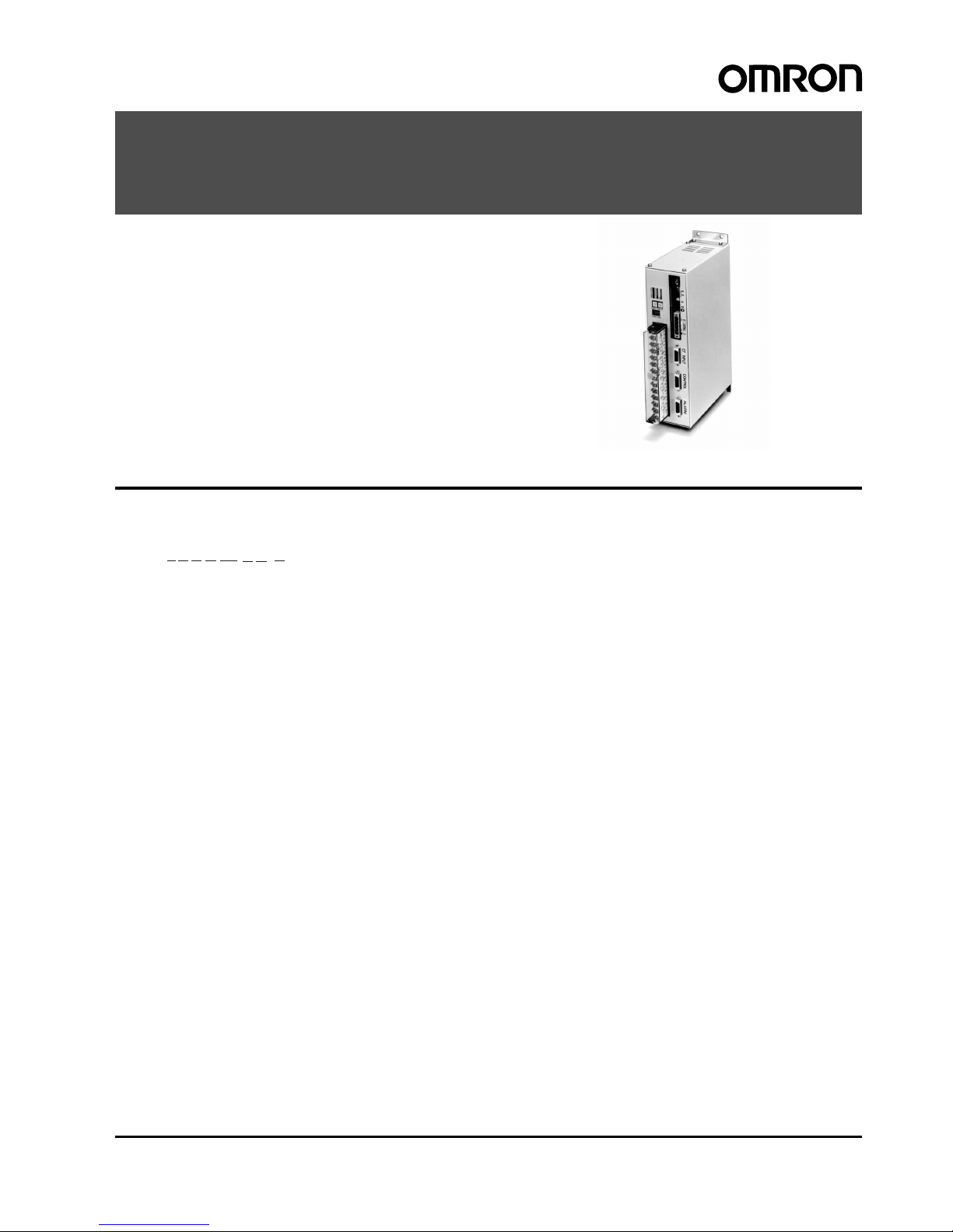
Multipoint Temperature Controller
E5ZE-8@D1@B-V2
Multipoint Temperature Controller Connects
to the Programmable Controller with Ease
• Conforms to De viceNet req uirements wit h remote I/O and FINS
message communications, thus connecting to a CompoBus/D
Master without prog rams f or remot e I/O commu nications an d to
OMRON’s Programmable Controller with ease for explicit message communicat ion s .
• High-speed inpu t sampling of only 0.2 s at the maxi mum of eigh t
temperature inputs.
Model Number Structure
■Model Number Legend
1. Number of Control Points
8: 8 channels
2. Control Method
A: Standard (heating or cooling)
V: Heating and cooling
3. Control Output (H e a ting Side)
Q: Voltage output (for driving SSR)
C: Current output
4. Heater Burnout and SSR Failure Detection (See note 1.)
H: Available
A: Not available
5. Communications Function
D1: DeviceNet
6. Input
TC: Thermocouple
P: Platinum resistance thermometer
7. Case
B: Provided (Models with case)
8. Version
V2: Supports explicit messages
Note: 1. Heater burnout and SSR failure detection are not available when the control output on the heating side is current output.
2. Refer to the List of Models for combinations of functions.
1 234
5
6
7
8
E5ZE-8@@@D1@B-V2
Page 2
2 Multipoint Temperature Controller E5ZE-8@D1@B-V2
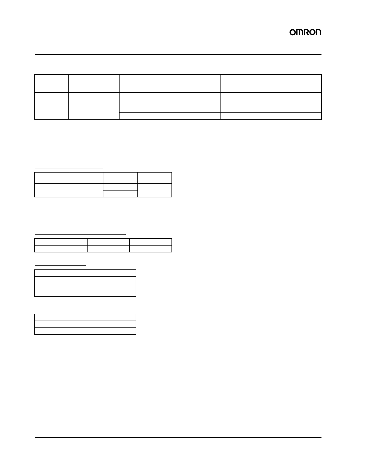
Ordering Information
■List of Models
Note: 1. Cooling control is possible by making a change in output operation.
2. Models without the heater burnout/SSR failure detection function are also available.
3. Cooling control output is an open collector output (NPN).
■Accessories (Order Separately)
Setting Display Unit
Note: Not all the functions of the E5ZE can be set, which should be
taken into consideration when designing the system. For details, refer to the E5ZD-SDL Setting Display Unit Datasheet
(H061).
Current Transformers (CT)
Special Cables
Recommended Power Supplies
No. of control
points
Control method Control output Heater burnout and
SSR failure detection
Input type
Thermocouple Platinum resistance
thermometer
8 Standard
(see note 1)
Voltage Available (see note 2) E5ZE-8AQHD1TCB-V2 E5ZE-8AQHD1PB-V2
Current Not available E5ZE-8ACAD1TCB-V2 E5Z E -8ACAD1PB-V2
Heating and cooling Voltage Available (see note 2) E5ZE-8VQHD1TCB-V2 E5ZE-8VQHD1PB-V2
Current (see note 3) Not available E5ZE-8VCAD1TCB-V2 E5ZE-8VCAD1PB-V2
Connecting
model
Connecting
part
Power supply Model
RS-232C Connector 100 to 240 VAC E5ZD-SDL1
24 VDC
Hole diameter 5.8 mm 12.0 mm
Model E54-CT1 E54-CT3
Model
E5ZE-CBL200
ES100-CT021-202 (25-pin)
ES100-CT023-202 (9-pin)
Series
S82J
S82K
Page 3

Multipoint Temperature Controller E5ZE-8@D1@B-V2 3
Specifications
■Ratings
Supply volt age 24 VDC
Operating voltage range 85% to 110% of rated supply voltage
Power cons um ption 15 W + 20% max. at rated supply voltage
Input Input type Thermocouple: K, J, R, S, T, E, B, N, L, U, W, PL-II
Platinum resistance thermometer: Pt100, JPt100
Input impedance Thermocouple: 1 M
Ω min.
Rated platinum resistance
thermometer current
1 mA
Control
outputs
Standard (Heating side) Voltage output (with short-circuit protecting function)
ON: 12
± 1.2 VDC
OFF: 0.5 VDC max.
Max. load current: 30 mA DC per point
Current output
Rated output range: 4 to 20 mA DC
Current output range: 0 to 22 mA DC
With an output value of 0%: 4
+0
/
–0.6
mA DC
With an output value of 100%: 20
+2
/–0 mA DC
Max. load resistance: 600
Ω per point
Cooling side Open collector output (NPN)
Max. applied voltage: 30 VDC
Max. load current: 50 mA DC per point
ON residual voltage: 2 VDC max.
OFF leakage current: 1 mA DC max.
Alarm outputs Temperature alarm: The total output of all control points (alarm 1 NPN open collector output and
alarm 2 NPN open collector output)
HB alarm (heater burnout detection): Total output of all control points (1-point NPN open collector
output)
HS alarm (SSR failure detection): Total output of all control points (1-point NPN open collector
output)
Temperature controller error output (memory, set value, or hardware error):
1-point NPN open collector output
Max. applied voltage: 30 VDC
Max. load current: 50 mA DC per point
No. of input control points 8 input and 8 control points
Setting method Via communication
Control modes ON/OFF control
Hybrid of advanced PID control and fuzzy control
Manual operation
Memory bank input No. of points: 8 for each control point
Designation method: Through communication or memory bank designation input
Memory bank designation inputs With contact signal input
ON short-circuit resistance: 1 k
Ω max.
OFF open resistance: 100 k
Ω min.
With no-contact signal input
ON residual voltage: 2 VDC max.
OFF leakage current: 1 mA DC max.
Page 4

4 Multipoint Temperature Controller E5ZE-8@D1@B-V2
■Input Ranges
Thermocouple
Platinum Resistance Thermometer
Note: 1. A temperature range is factory-set to a range of –200° to
1,300
°C (for K(CA)) or –100.0° to 500.0°C (for Pt 100).
2. Thermocouple W is W/ Re5-26 (tungsten rhenium 5, tungsten rhenium 26).
■Characteristics
Input
(switch
selectable)
K (CA)
Chromel
vs. alumel
(see
note 1)
J (IC)
Iron vs.
constan-
tan
R
Platinum
vs. Plati-
num rhod-
ium 13%
S
Platinum
vs. Plati-
num rhod-
ium 10%
T (CC)/U
Copper
vs. con-
stantan
E (CRC)
Chromel
vs. con-
stantan
B
Platinum
rhodium
30% vs.
platinum
rhodium
6%
N
Nichrosil
vs. nisil
L
Iron vs.
constan-
tan
U
Copper
vs. con-
stantan
W
(see
note 2)
PL-II
(Platinum)
Range
°C –200 to
1,300
–100 to
850
0 to 1,700 0 to 1,700 –200 to
400
0 to 600 100 to
1,800
0 to 1,300 –100 to
850
–200 to
400
0 to 2,300 0 to 1,300
°F –300 to
2,300
–100 to
1500
0 to 3,000 0 to 3,000 –300 to
700
0 to 1100 300 to
3,000
0 to 2,300 –100 to
1,500
–300 to
700
32 to 4,100 0 to 2,300
Setting no. 0123456789AB
Min. setting
unit
1
°C or 0.1°C
Input
(switch selectable)
Pt 100
(see note 1)
JPt 100
Range
°C –100.0 to 500.0 –100.0 to 500.0
°F –100.0 to 900.0 –100.0 to 900.0
Setting no. 01
Min. setting unit 1
°C or 0.1°C
Measurement accuracy (see note) Thermocouple:
(
±0.3% of the process value or ±2°C, whichever greater) ±1 digit max.
(
±0.3% of the process value or ±3.6°F, whichever greater) ±1 digit max.
Platinum resistance thermometer:
(
±0.3% of the process value or ±0.8°C, whichever greater) ±1 digit max.
(
±0.3% of the process value or ±1.5°F, whichever greater) ±1 digit max.
Hysteresis 0.0
° to 99.9°C/°F for ON/OFF control only (in units of 0.1°C/°F)
Cooling coefficient 0.0 to 10.0 (in units of 0.1)
Proportional band 0.0
° to 999.9°C/°F (in units of 0.1°C/°F)
Cooling side: Cooling coefficient
× Proportional band
Integral (reset) time 0 to 3,999 s (in units of 1 s) (for both heating and cooling)
Derivative (rate) time 0 to 3,999 s (in units of 1 s) (for both heating and cooling)
Control period Heating side: 1 to 99 s (in units of 1 s)
Cooling side: 1 to 99 s (in units of 1 s)
Sampling period 200 ms for 8 control points
Dead band/overlap band –999
° to 999°C/°F (in units of 1°C/°F)
Alarm output setting range –999
° to 9999°C/°F, 0 to 9999°C/°F (upper- and lower-limit alarm) (in units of 1°C/°F)
–999.9
° to 9999.9°C/°F, 0.0 to 9999.9°C/°F (upper- and lower-limit alarm) (in units of 0.1°C/°F) (see note
3)
Fuzzy strength 0% to 99% (in units of 1%)
Fuzzy scale 1 0.2
° to 999.9°C/°F (in units of 0.1°C/°F)
Fuzzy scale 2 0.02
° to 99.99°C/s or °F/s (in units of 0.01°C/s or °F/s)
Set value backup Lithium battery
Set value backup period 10 years min. provided that the ambient temperature is within the room temperature
Insulation resistance 20 M
Ω min. between the FG terminal and all analog input terminals (at 500 VDC)
Dielectric strength A leakage current of 1 mA A C max. with 500 VA C for 1 minutes between the FG terminal and all analog
input terminals
Vibration resistance
Malfunction: 10 to 55 Hz, 15 m/s
2
for 8 min each in X, Y, and Z directions
Destruction: 10 to 55 Hz, 20 m/s
2
for 8 min each in X, Y, and Z directions
Shock resistance
Malfunction: 150 m/s
2
, 3 times each in 6 directions
Destruction: 200 m/s
2
, 3 times each in 6 directions
Ambient temperature Operating: 0
° to 55°C (with no icing or condensation)
Storage: –25
° to 65°C (with no icing or condensation)
Ambient humidity Operating: 35% to 85%
Storage: 35% to 95%
Page 5

Multipoint Te mperature Controller E5ZE-8@D1@B-V2 5
Note: 1. The measurement accuracy of the E5ZE used with a thermocouple B at 400°C or 750°F max. is not guaranteed. The following measure-
ment accuracy values are applied to the E5ZE.
K and T at –100
°C max. and U: ±3°C ±1 digit max.
K and T at –100
°F max. and U: ±5.4°F ±1 digit max.
R, S, and W at 200
°C max., and B at 1,000°C max.: ±4°C ±1 digit max.
R, S, and W at 400
°F max., and B at 1,800°F max.: ±7.2°F ±1 digit max.
2. The measurement accuracy of the E5ZE used with any thermocouple is 1
°C/°F. The thermocouple can be used under the following tem-
perature ranges to increase the measurement accuracy to as high as 0.1
°C/°F.
K thermocouple: 0.0
°C to 1,300.0 °C, 0.0 °F to 2,300.0 °F
T or U thermocouple: 0.0
°C to 400.0 °C, 0.0 °F to 700.0 °F
N thermocouple: 400.0
°C to 1,300.0 °C, 700.0 °F to 2,300.0 °F
J, E, L, or PLII thermocouple: Any temperature
3. Upper limit is 3000.0
°C/°F when set from CompoBus/D.
■Communications Specifications
Conforming to DeviceNet Communications Protocol
For details, refer to the CompoBus/D (DeviceNet) Operation Manual (W267) and the E5ZE-8 Communication Manual (H114).
Note: 1. An external term inator must be attached.
2. Indicates the distance between nodes farthest from each other.
3. The maximum network length is 100 m if a thin dedicated cable is applied to the trunk line.
!NOTICE
This product has been tested by ODVA’s authorized Independent
Test Lab and found to comply with ODVA Conformance Test Software Version A-13.
For the specifications of objects in details, refer to the E5ZE-8 Com-
munication Manual (H114).
DeviceNet Communications Items
Note: Items for the OUT side of remote I/O are not included.
Dimensions With casing: 173.5 x 253 x 65 mm max.
Enclosure rating IP00
Weight With casing:1,700 g max.
Connection method Multi-drop or T-branching (see note 1)
Baud rate 500/250/125 kbps
Communications media Dedicated 5-wire cable (with 2 communications wires, 2 power wires, and 1 shield wire)
Communications distance Baud rate
Maximum network length (see note 2) Branch line length Total branch line length
500 kbps 100 m max. (see note 3) 6 m max. 39 m max.
250 kbps 250 m max. (see note 3) 6 m max. 78 m max.
125 kbps 500 m max. (see note 3) 6 m max. 156 m max.
Remote I/O points IN: 14 / OUT: 9
Error control CRC error and node address duplication check
Remote I/O communications IN: PV (process value) (8 points), Alarms 1 and 2 status, AT status, HB alarm status,
HS alarm status, and error status
OUT: RUN/STOP and SP (set point) (8 points)
Explicit message communications All read and write parameters (See note.)
Page 6

6 Multipoint Temperature Controller E5ZE-8@D1@B-V2
System Configuration
!Caution
Be sure to use the above Units, which save wiring effort, and connection cables for the prevention of malfunctions or accidents that
may be caused by mistakes in wiring.
Dimensions
Note: All units are in millimeters unless otherwise indicated.
ES100-CT021-202 or
ES100-CT023-202
Power supply input
Regulated DC
power supply
Temperature
sensor input
Thermocouple
Platinum resistance
thermometer
E5ZE-8@D1@B-V2
E5ZE-CBL200
E5ZE-CBL200
E5ZE-CBL200
XW2D-20G6
Connector−Terminal
Conversion Unit
XW2D-20G6
Connector−Terminal
Conversion Unit
G7TC-OC08/G7TC-OC16
I/O Block
G70D-V@O@16
Relay terminal
Host Unit Compatible with Explicit
Message Communications
OMRON's C200HW-DRM21-EV1,
CVM1-DRM21-EV1 and CS1W-DRM21
Note: When replacing with an E5ZE-
8@D1@B, part of the ladder
program must be changed.
E5ZD-SDL1
Setting Display Unit
Note: Do not use the RS-232C auxiliary jack for permanent
connection when the E5ZE is mounted to equipment.
E5ZE-8@D1-@B-V2
Mounting
bracket
Mounting Holes
Mounting
bracket
Four, M4
Page 7

Multipoint Te mperature Controller E5ZE-8@D1@B-V2 7
Precautions
Mounting the Controllers
Side-by-side, Close Mounting
Saves space and improves wiring efficiency.
Wall Mounting
Can be mounted to places with limited depth.
General Mounting Precautions
The side of the E5ZE with the terminal block and connectors must
not face up, otherwise operating errors may result.
Prepare four M4 screws to mount the E5ZE to control panels. Use
flat washers and spring washers with screws to mount the E5ZE to
control panels so that the screws will not loosen.
The mounting brackets must be attached to the E5ZE with the four
M3
×6 screws provided with the E5ZE and each of the screws should
be tightened to a torque of 0.43 to 0.58 N·m, or 4.4 to 5.9kgf·cm.
Do not mount as shown in the following diagram.
Control panel
Up
Control panel
Up
Control panel
Incorrect
Page 8

8
In the interest of product im pr ovement, specifications are subject to change without notice.
ALL DIMENSIONS SHOWN ARE IN MILLIMETERS.
To convert millimeters into inches, multiply by 0.03937. To convert grams into ounces, multiply by 0.03527.
Cat. No. H103-E1-02
OMRON Corporation
Industrial Automation Company
Industrial Devices and Components Division H.Q.
Measuring Components Department
Shiokoji Horikawa, Shimogyo-ku,
Kyoto, 600-8530 Japan
Tel: (81)75-344-7080/Fax: (81)75-344-7189
Printed in Japan
0703-0.3M (1098) (A)
Warranty and Limitations of Liability
■WARRANTY
OMRON's exclusive warranty is that the products are free from defects in materials and workmanship for a period of one year (or other period if
specified) from date of sale by OMRON.
OMRON MAKES NO WARRANTY OR REPRESENT ATION, EXPRESS OR IMPLIED, REGARDING NON-INF RINGEMENT , MERCHANT ABILIT Y ,
OR FITNESS FOR PARTICULAR PURPOSE OF THE PRODUCTS. ANY BUYER OR USER ACKNOW LEDGES THAT THE BUYER OR USER
ALONE HAS DETERMINED THAT THE PRODUCTS WILL SUITABLY MEET THE REQUIREMENTS OF THEIR INTENDED USE. OMRON
DISCLAIMS ALL OTHER WARRANTIES, EXPRESS O R IMP L IE D.
■LIMITATIONS OF LIAB ILITY
OMRON SHALL NOT BE RESPONSIBLE FOR SPECIAL, INDIRECT, OR CONSEQUENTIAL DAMAGES, LOSS OF PROFITS, OR
COMMERCIAL LOSS IN ANY WAY CONNECTED WITH THE PRODUCTS, WHETHER SUCH CLAIM IS BASED ON CONTRACT, WARRANTY,
NEGLIGENCE, OR STRICT LIABILITY.
In no event shall the responsibility of OMRON for any act exceed the individual price of the product on which liability is asserted.
IN NO EVENT SHALL OMRON BE RESPONSIBLE FOR WARRANTY, REP AIR, OR O T HER CLAIMS REGARDING THE PRODUCTS UNLESS
OMRON'S ANALYSIS CONFIRMS THAT THE PRODUCTS WERE PROPERLY HANDLED, STORE D , INSTALLED, AND MAINTAINED AND NOT
SUBJECT TO CONTAMINATION, ABUS E, MISUSE, OR INAPPROPRIATE MODIFICATION OR REPAIR.
Application Considerations
■SUITABILITY FOR USE
OMRON shall not be responsible for conformity with any standards, codes, or regulations that apply to the combination of products in the
customer's application or use of the products.
At the customer's request, OMRON will provide applicab le third party certification documents identifying ratings and limitations of use that apply
to the products. This information by itself is not sufficient for a complete determination of the suitability of the products in combination with the end
product, machine, system, or other application or use.
The following are some examples of applications for which particular attention must be given. This is not intended to be an exhaustive list of all
possible uses of the products, nor is it intended to imply that the uses listed may be suitable for the products.
• Outdoor use, uses involving potential chemical contamination or electrical interference, or conditions or uses not described in this catalog.
• Nuclear energy control systems, combustion systems, railroad systems, aviation systems, medical equipment, amusement machines, vehicles,
safety equipment, and installations subject to separate industry or government regulations.
• Systems, machines, and equipment that could present a risk to life or property.
Please know and observe all prohibitions of use applicable to the products.
NEVER USE THE PRODUCTS FOR AN APPLICATION INVOL V ING SERIOUS RISK TO LIFE OR PROPER TY WITHOUT ENSURING THAT THE
SYSTEM AS A WHOLE HAS BEEN DESIGNED TO ADDRESS THE RISKS, AND THAT THE OMRON PRODUCTS ARE PROPERLY RATED
AND INSTALLED FOR THE INTENDED USE WITHIN THE OVERALL EQUIPMENT OR SYSTEM.
 Loading...