

Omron E5ZE-8AAAMTC-E, E5ZE-8AAAMP-E, E5ZE-8VAAMTC-E, E5ZE-8VAAMP-E, E5ZE-8AAAMTCB-E Datasheet
...Page 1
Multipoint Temperature Controller E5ZE 1
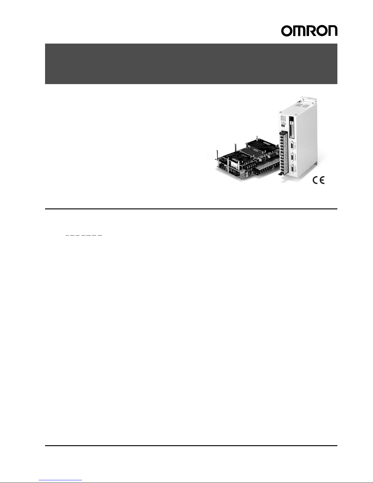
Multipoint Temperature Controller
E5ZE
Compact, Easy-to-mount Multipoint
Temperature Controller (Casing)
Compact, Easy-to-use, Board-type
Multipoint Temperature Controller (Open)
• Easy-to-mount, user-friendly models with casing.
• 50% small er in projection space than the previous E5ZD Multipoint Temper a ture Cont roll er.
• Connector terminal block saves wiring effort.
• High-speed input sampling.
• Heating/cooling model s are a vailable.
Note: Open models do not bear CE markings.
Model Number Structure
■Model Number Legend
1. Control Point
8: 8
2. Control Method
A: Standard
V: Heating/cooling
3. Control Output
A: Option (see note 1)
4. Heater Burnout and SSR Failure Detection (see note 2)
A: Option (see note 3)
5. Communications
M: Option (see note 4)
6. Input Type
TC: Thermocouple
P: Platinum resistance thermometer
7. Casing
B: Yes
Blank:No (open type)
Note: 1. The E53-E8Q Voltage Output Unit or the E53-E8C Current
Output Unit can be used with the E5ZE. The E53-E8Q Voltage Output Unit and the E53-E8C Current Output Unit are
sold separately.
2. The heater burnout and SSR failure detection function of the
E5ZE will be invalid if the heating side control output of the
E5ZE is current output.
3. The E54-E8CT CT Input Unit is required for the heater burnout and SSR failure detection. The E54-E8CT CT Input Unit
is sold separately .
4. The E53-E01 Communications Unit for RS-232C communication or the E53-E04 Communications Unit for RS-422 and
RS-485 communication can be used with the E5ZE. The
E53-E01 Communications Unit and the E53-E04 Communications Unit are sold separately.
E5ZE-8@AAM@@-E
1 2 3 4 5 6 7
Page 2
2 Multipoint Temperature Controller E5ZE
Ordering Information
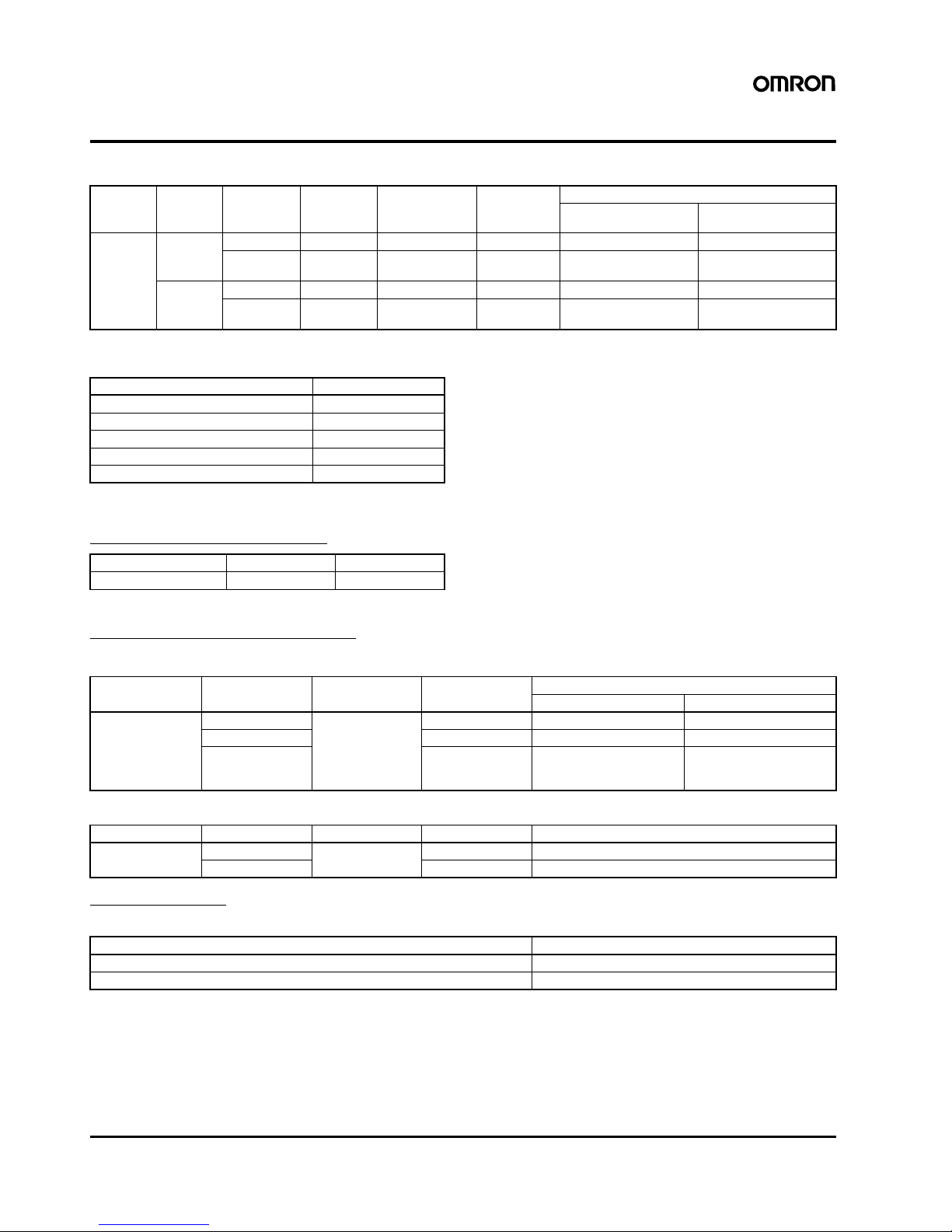
■List of Models
■I/O Units (Order Separately)
■Accessories (Order Separately)
Current Transformers (CT)
Note: The above CTs are not provided with the E5ZE.
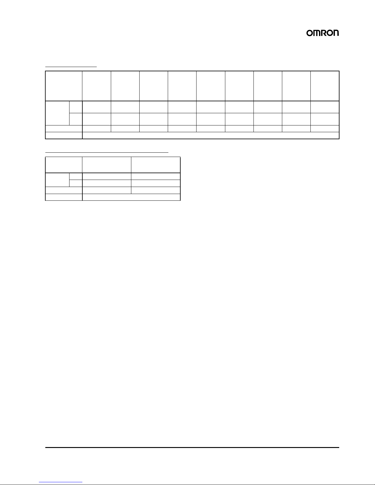
Recommended Power Supply
S82J Switching Power Supply
S82K Switching Power Supply
Wiring Devices
Connector Terminal Conversion Unit
No. of
control
points
Casing Control
method
Control
output
Heater burnout
and SSR failure
detection
Communica-
tions
Input type
Thermocouple Platinum resistance
thermometer
8 No Standard Option Option Option E5ZE-8AAAMTC-E E5ZE-8AAAMP-E
Heating and
cooling
Option Option Option E5ZE-8VAAMTC-E E5ZE-8VAAMP-E
Yes Standard Option Option Option E5ZE-8AAAMTCB-E E5ZE-8AAAMPB-E
Heating and
cooling
Option Option Option E5ZE-8VAAMTCB-E E5ZE-8VAAMPB-E
Units Models
RS-232C Communications Unit E53-E01
RS-422/485 Communications Unit E53-E04
CT Input Unit E54-E8CT
Voltage Output Unit E53-E8Q
Current Output Unit E53-E8C
Hole diameter 5.8 mm 12.0 mm
Model E54-CT1 E54-CT3
Input volta ge Power ra tings Output voltage Output current Model
Open-frame type Covered-type
100 to 240 VAC 50 W 24 V 2.1 A S82J-05024A S82J-05024D
100 W 4.5 A S82J-10024A S82J-10024D
150 W 6.5 A S82J-15024A
S82J-15024B
S82J-15024C
S82J-15024D
S82J-15024E
S82J-15024F
Input volta ge Power ra tings Output voltage Output current Model
100/200 VAC 50 W 24 V 2.1 A S82K-05024
100 W 4.2 A S82K-10024
Specifications Model
20-pole, M2.4 terminal block XW2B-20G4
20-pole, M3.5 terminal block XW2B-20G5
Page 3

Multipoint Temperature Controller E5ZE 3
I/O Block
Connecting Cable
Setting Display Unit
Note: 1. The Setting Display Unit is originally for use with the E5ZD . Be careful when using the Setting Display Unit with the E5ZE as some of the
E5ZE’s functions cannot be used with the Setting Display Unit.
2. Each model available as a 100-to-240-VAC type or 24-VDC type. (Exception: The E5ZD-SDLM is available only as a 24-VDC type).
Specifications Model
8-point (SPST-NO x 8) relay output with NPN DC coil (+ common) G7TC-OC08
16-point (SPST-NO x 16) relay output with NPN DC coil (+ common) G7TC-OC16
16-point (SPST-NO x 16) relay output with NPN DC coil (+ common) G7VC-OC16
16-point (SPST-NO x 16) SSR AC output with NPN DC coil (+ common) G7VC-OA16
16-point (SPST-NO x 16) SSR DC output with NPN DC coil (+ common) G7VC-OD16
Specifications Model
2 m long E5ZE-CBL200
Connecting model Connecting part Model (see note 2)
RS-232C Connector E5ZD-SDL1
RS-422 Terminal block E5ZD-SDL2-X
RS-485 Terminal block E5ZD-SDL3-X
E5ZD-SDLM
Page 4

4 Multipoint Temperature Controller E5ZE
Specifications
■Ratings
Supply voltage 24 VDC
Operating voltage range 85% to 110% of rated supply voltage
Power consumption 15 W + 20% max. at rated supply voltage
Input Input type Thermocouple: K, J, R, S, T, E, B, N, L, U, W , PL-II
Platinum resistance thermometer: Pt100, JPt100
Input impedance Thermocouple: 1 M
Ω min.
Rated platinum resistance
thermometer current
1 mA
Control outputs Voltage output (with short-circuit protecting function)
ON: 12
± 1.2 VDC
OFF: 0.5 VDC max.
Max. load current: 30 mA DC per point
Current output
Rated output range: 4 to 20 mA DC
Current output range: 0 to 22 mA DC
With an output value of 0%: 4
+0
/
–0.6
mA DC
With an output value of 100%:20
+2
/–0 mA DC
Max. load resistance: 600
Ω per point
Open collector output (NPN) (cooling side only)
Max. applied voltage: 30 VDC
Max. load current: 50 mA DC per point
ON residual voltage: 2 VDC max.
OFF leakage current: 1 mA DC max.
Alarm outputs Te mperature alar m: The total output of all control points (alarm 1 NPN open collector output and
alarm 2 NPN open collector output)
HB alarm (heater burnout detection): Total output of all control points (1-point NPN open collector
output)
HS alarm (SSR failure detection): Total output of all control points (1-point NPN open collector
output)
Temperature controller error output (memory, set value, or hardware error):
1-point NPN open collector output
Max. applied voltage: 30 VDC
Max. load current: 50 mA DC per point
No. of input c on t rol points 8 input and 8 control points
Setting method Via communication
Control method ON/OFF control
Hybrid of 2-PID control and fuzzy control
Manual operation
Page 5
Multipoint Temperature Controller E5ZE 5
■Input Ranges
Thermocouple
Platinum Resistance Thermometer
Note: 1. T he set ting selector set to 0 (K) or 0 (Pt 100) before shipping.
2. A temperature range is factory-set to a range of –200
° to 1,300°C (K(CA)) or −100.0° to 500.0°C (Pt 100).
3. Thermocouple W is W/Re5-26 (tungsten rhenium 5, tungsten rhenium 26).
Input (switch
selectable)
(see note 1)
K (CA)
Chromel vs.
alumel (see
note 2)
J (IC)/L
Iron vs.
constantan
R/S
Platinum
vs. Plati-
num rhod-
ium 10%
T (CC)/U
Copper vs.
constantan
E (CRC)
Chromel vs.
constantan
B
Platinum
rhodium
30% vs.
platinum
rhodium 6%
N
Nichrosil
vs. nisil
W
(see note 3)
PL-II
(Platinum)
Range
°C −200 to
1,300
−100 to 850 0 to 1,700 −200 to 400 0 to 600 100 to 1,800 0 to 1,300 0 to 2,300 0 to 1,300
°F −300 to
2,300
−100 to
1,500
0 to 3,000 −300 to 700 0 to 1,100 300 to 3,000 0 to 2,300 32 to 4,100 0 to 2,300
Setting no. 01/82/34/9567AB
Min. setting unit 1
°C or 0.1°C
Input (switch
selectable)
(see note 1)
Pt 100 JPt 100
Range
°C −100.0 to 500.0 −100.0 to 500.0
°F −100.0 to 900.0 −100.0 to 900.0
Setting no. 01
Min. setting unit 1
°C or 0.1°C
Page 6

6 Multipoint Temperature Controller E5ZE
■Characteristics
Note: 1. The measurement accuracy of the E5ZE used with a ther mocouple B at 400°C or 750°F max. is not guaranteed. The following
measurement accuracy values are applied to the E5ZE.
K and T at
−100°C max. and U: ±3°C ±1 digit max.
K and T at
−100°F max. and U: ±5.4°F ±1 digit max.
R, S, and W at 200
°C max., and B at 1,000°C max.: ±4°C ±1 digit max.
R, S, and W at 400
°F max., and B at 1,800°F m ax.: ±7.2°F ±1 digit max.
2. The measurement accuracy of the E5ZE used with any thermoc ouple is 1
°C/°F. The thermocouple can be used under the following
temperature ranges to increase the measurement accuracy to as high as 0.1
°C/°F.
K thermocouple: 0.0
°C to 1,300.0 °C, 0.0 °F to 2,300.0 °F
T or U thermocouple: 0.0
°C to 400.0 °C, 0.0 °F to 700.0 °F
N thermocouple: 400.0
°C to 1,300.0 °C, 700.0 °F to 2,300.0 °F
J, E, L, or PLII thermocouple: Any temperature
3. To ensure EMC conformance, refer to Wiring for Conformance to the EMC Directives on page 16.
Measurement accuracy (see note) Thermocouple:
(
±0.3% of the process value or ±2°C, whichever greater) ±1 digit max.
(
±0.3% of the process value or ±3.6°F, whichever greater) ±1 digit max.
Platinum resistance thermometer:
(
±0.3% of the process value or ±0.8°C, whichever greater) ±1 digit max.
(
±0.3% of the process value or ±1.5°F, whichever greater) ±1 digit max.
Hysteresis 0.0
°C/°F to 99.9°C/°F for ON/OFF control only (in units of 0.1°C/°F)
Cooling coefficient 0.0 to 10.0 (in units of 0.1)
Proportional band 0.0
°C/°F to 999.9°C/°F (in units of 0.1°C/°F)
Cooling side: Cooling coefficient x Proportional band
Integral (reset) time 0 to 3,999 s (in units of 1 s) (for both heating and cooling)
Derivative (rate) time 0 to 3,999 s (in units of 1 s) (for both heating and cooling)
Control period Heating side:1 to 99 s (in units of 1 s)
Cooling side: 1 to 99 s (in units of 1 s)
Sampling period Approx. 200 ms for 8 control points
Dead band/overlap band
−999°C/°F to 999°C/°F (in units of 1°C/°F)
Alarm output setting range
−999°C/°F to 9999°C/°F, 0 to 9999°C/°F (upper- and lower-limit alarm) (in units of 1°C/°F)
−999.9°C/°F to 9999.9°C/°F, 0.0 to 9999.9°C/°F (upper- and lower-limit alarm) (in units of 0.1°C/°F)
Fuzzy strength 0% to 99% (in units of 1%)
Fuzzy scale 1 0.2
°C/°F to 999.9°C/°F (in units of 0.1°C/°F)
Fuzzy scale 2 0.02
°C/s or °F/s to 99.99°C/s or °F/s (in units of 0.01°C/s or °F/s)
Set value backup Lithium battery
Set value backup period 10 years min. at room temperature
Insulation resistance 20 M
Ω min. between the FG terminal and all analog input terminals (at 500 VDC)
Dielectric strength A leakage current of 1 mA A C max. with 500 V AC for 1 minutes between the FG terminal and all analog
input terminals
Vibration resistance
Malfunction: 10 to 55 Hz, 10 m/s
2
(1G) for 10 min each in X, Y, and Z directions
Destruction: 10 to 55 Hz, 20 m/s
2
(2G) for 2 hrs each in X, Y, and Z directions
Shock resistance
Malfunction: 150 m/s
2
(15.3G), 3 times each in 6 directions
Destruction: 200 m/s
2
(20.4G), 3 times each in 6 directions
Ambient temperature Operating:
−10°C to 55°C (with no icing or condensation)
Storage:
−25°C to 65°C (with no icing or condensation)
Ambient humidity Operating: 35% to 85%
Storage: 35% to 95%
Dimensions Without casing: 169.5 x 192 x 58 mm max.
With casing: 173.5 x 200 x 65 mm max.
Degree of protection IP00
Weight Without casing: 900 g max.
With casing: 1,700 g max.
EMC Em ission Enclos ure: EN55011 Group 1 class A
Immunity ESD: EN61000-4-2:4 kV contact discharge (level 2)
8 kV air discharge (level 3)
Immunity RF-interference: ENV50140: 10 V/m (amplitude modulated, 80 MHz to 1 GHz)
(level 3)
10 V/m (pulse modulated, 900 MHz)
Immunity Conducted Disturbance: ENV50141: 10 V (0.15 to 80 MHz) (level 3)
Immunity Burst: EN61000-4-4:2 kV power-line (level 3)
Approved standards Conforms to EN50081-2, EN50082-2 (see note 3)
Page 7

Multipoint Temperature Controller E5ZE 7
■Communications Specifications
Note: 1. The maximum total cable length must not exceed the following limits.
RS-422: 500 m, RS-232C: 15 m, RS-485: 500 m
• Recommended connectors:
RS-232C: XM2@ D-sub connector (25 pin) (OMRON)
2. A maximum of 16 Temperature Controllers can be connected to one host computer using serial communications (RS-422 or RS-485).
■Communications
• Set point
• Process value
• Alarm value
• Alarm mode
• Hysteresis
• Propor tional band
• Integral time
• De rivative time
• Output value
• Auto-tuning (AT) start/stop
• Heater burnout detection set value
• Control start/stop
• Control memory bank
• Cooling coefficient (see note)
• Dead band/overlap band (see note)
• Fuzzy strength
• Fuzzy scale 1, 2
Note: For heating and cooling control models only.
Item RS-232C RS-422 RS-485
Communications method Half-duplex
Connecting method 25-pin D-sub connector 5-pole terminal block (with M3 screws)
Transmission line configuration 3-wire 4-wire 2-wire
Transmission line type Direct line Multi-drop line
Synchronization method Start-stop synchronization (asynchronous)
Baud rate 2,400/4,800/9,600/19,200 bps
Transmission code ASCII
No. of stop bits 2
Parity Even parity
Character length 7 bits
Error detection Vertical parity and FCS (frame check sequence)
Communications unit no. 0 to F (hexadecimal)
Transmission and reception switch ing time --- 20 ms max.
Max. transmission path 15 m 500 m in total
No. of controllers connected in parallel --- 16 (excluding host system)
Page 8

8 Multipoint Temperature Controller E5ZE
■E5ZD-SDL Ratings/Characteristics
Ratings
Characteristics
Note: The connection method must coincide with the communications specifications of the E5ZE Multipoint Temperature Controller.
Supply voltage 100 to 240 VAC, 50/60 Hz or 24 VDC
Operating voltage range 85% to 110% of rated supply voltage
Power consumption Appro x . 12 W (at 100 VAC) to 18 W (at 240 VAC), approx. 13 W (at 24 VDC)
Setting method Digital setting via Up and Down Keys
Display method Digital (character heights: PV: 15 mm, SV: 11 mm, UNIT/CH/BK: 11 mm)
(color PV: red, SV: green, UNIT/CH/BK: orange)
Other functions Key protection
Display group selection
Display scan function
Others also provided
Sampling period 500 ms, 1 s (selectable)
Vibration resistance
Malfunction: 2 to 55 Hz, 19.6 m/s
2
for 10 min each in X, Y, and Z directions
Destruction: 10 to 55 Hz, 0.75-mm for 2 hrs each in X, Y, and Z directions
Shock resistance
Malfunction: 196 m/s
2
for 3 times each in 6 directions
Destruction: 294 m/s
2
for 3 times each in 6 directions
Ambient temperature Operating:
−10°C to 55°C (with no icing)
Ambient humidity Operating: 35% to 85%
Weight Approx. 450 g
Degree of protection Front panel: IEC standard IP50
Rear case: IEC standard IP20
Terminals: IEC standard IP00
Connectio n m e t h od RS-232C, RS-422, RS-485
Communications speed: 9,600 bps
Connecting device: E5ZD/E5ZE Multipoint Temperature Controller series
Max. number of E5ZD/E5ZE Multipoint Temperature Controllers which can be connected
RS-232C: 1
RS-422: 16
RS-485: 16
Page 9

Multipoint Temperature Controller E5ZE 9
Dimensions
Note: All units are in millimeters unless otherwise indicated.
*
*
*
*
220±0.4
40±0.2
180
±0.2
t
2
t
1
E5ZE-8@AAM@B-E
Mounting Holes
E5ZE-8@AAM@-E
Mounting Holes
Mounting StudPanel-mounting Screws
Mounting bracket
Mounting bracket
Mounting studs (5 points)
Five, 3.5 dia.
Five, R5
Five, 3.5 dia.
M3 depth: 8
Mounting
bracket
Mounting
fixed screw
The mounting brackets
can be fixed to the position marked with *.
M3 x 6
stud fixing
screw
Prepare the following screws.
Size: M3 x l
t + t
1
+ t2 + 2.5 < l < t + t1 + t2 + 7.8
t: Panel thickness
t
1
: Spring washer thickness
t
2
: Flat washer thickness
Material: Iron or stainless
Page 10

10 Multipoint Temperature Controller E5ZE
Connections
■System Configuration
Devices Connectable to the E5ZE
Connections
Use E5ZE-CBL@@@ Connecting Cables to connect the following devices to the E5ZE.
• XW2B-20G4 and XW2B-20G5 Connector Terminal Conversion Units
• G7TC-OC08, G7TC-OC16, G7VC-OC16, G7VC-OD16, and G7VC-OA16 I/O Blocks
!Caution
Do not connect any device other than those listed above to the
E5ZE using E5ZE-CBL@@@ Connecting Cables, or the E5ZE may
malfunction or accidents may result.
Power supply input
Temperature sensor input
Thermocouple
Communications interface
Host system
E5ZD-SDL Setting Display Unit
Current T ransformer (CT) input
G7TC-OC16
G7TC-OC08
E5ZE-CBL@@@
E5ZE-CBL@@@
E5ZE-CBL@@@
CT INPUT CONTROL
Computer
E5ZE
ALARM
Regulated DC
power supply
Platinum
resistance
thermometer
RS-232C,
RS-422, or
RS-485
CV500-TDL21 T emperature
Controller Data
Link Unit
XW2B-20G4
XW2B-20G5
Control output
Memory bank designated input
XW2B-20G4
XW2B-20G5
Alarm output
Cooling side control output (heating and cooling
control models only)
XW2B-20G4
XW2B-20G5
G7VC-OC16
G7VC-OA16
G7VC-OD16
Page 11

Multipoint Temperature Controller E5ZE 11
■External Conne ction
Terminal Block Connections
Thermocouple
A thermocouple has polarity. C onnect thermocouples to the terminal
block correctly using compensating conductor that are suitable for
the thermocouples.
Be sure to use the cold junction compensator (no. 13 and 15) pro vided with the E5ZE. The lot and serial numbers of the cold junction
compensator must be identical to those of the E5ZE. Do not touch
the cold junction compensator while operating the E5ZE.
The number of each of the above thermocouples is a point number.
Platinum Resistance Thermometer
Make sure there in no difference in resistance among the three conductor of each platinum resistance thermometer used with the E5ZE.
Do not short-circuit terminals 7, 8, 20, and 21.
The number of each of the above platinum resistance thermometer is
a point number.
Connecting to Connector Terminal Conversion Unit
Control Output and Memory Bank Designation Input
Current Transformer (CT) Input
DC−
DC+
DON'T USE
DON'T USE
DON'T USE
DON'T USE
DON'T USE
FG
Thermo-
couple 0
Thermo-
couple 1
Thermo-
couple 2
Thermo-
couple 3
Thermocouple 4
Thermocouple 5
Thermocouple 6
Thermocouple 7
DON'T
TOUCH
DC
−
DC+
DON'T USE
FG
Platinum
resistance
thermometer 0
Platinum
resistance
thermometer 1
Platinum
resistance
thermometer 2
Platinum
resistance
thermometer 3
Platinum
resistance
thermometer 4
Platinum
resistance
thermometer 5
Platinum
resistance
thermometer 6
Platinum
resistance
thermometer 7
DON'T
USE
Bit 2
1
MB common
Control output
XW2B-20G4 or
XW2B-20G5
Connector T erminal
Conversion Unit
Bit 22Bit 2
0
Memory bank
designation input
Point
number
CT input
Not used
Not used
XW2B-20G4 or
XW2B-20G5
Connector T erminal
Conversion Unit
Point
number
Page 12

12 Multipoint Temperature Controller E5ZE
Alarm Output and Cooling Side Control Output (For Heating and Cooling Control Model Only)
Connecting to G7VC-O@16 I/O Block
Alarm Output and Coolin g Side Co ntr ol O utput ( For He atin g and Co oling Contr ol Mode ls Onl y)
Connecting to G7TC-OC@@ I/O Block
G7TC-OC08 Alarm Output
Not used
Not used
HS alarm
Alarm output
Alarm 1
HB alarm
Alarm 2
Common
Not used
Common
XW2B-20G4 or
XW2B-20G5
Connector T erminal
Conversion Unit
Cooling side control output (Do not use these terminals when
using an E5ZE Standard Model.)
Point
number
Temperature
Controller error
Not used
HS alarm
Alarm output
Alarm 1
HB alarm
Alarm 2
Cooling side control output
G7VC-OC16,
G7VC-OA16, or
G7VC-OD16
I/O Block
Temperature
Controller error
Drive power supply
for G7VC (24 VDC)
A2 to A6
Common
A12 to A19
Common
Do not use these terminals when
using an E5ZE Standard Model.
Point
number
HS alarm
Alarm output
Alarm 1
HB alarm
Alarm 2
Not used
Not used
G7TC-OC08 I/O
Block
Drive power
supply for G7TC
(12 or 24 VDC)
Temperature
Controller error
Page 13

Multipoint Temperature Controller E5ZE 13
G7TC-OC16 Alarm Output and Cooling Side Control Output (For Heating and Cooling Control
Models Only)
Communication Interfaces
RS-232C
Pin Assignments
Electrical characteristics: Conforming to EIA RS-232C
Synchronization clock: Inter nal
RS-422 and RS-485
RS-422
Electrical characteristics: Conforming to EIA RS-422
Synchronization clock: Internal
Maximum E5ZE Units connectable: 16 (excluding host system)
Transmission length: 500 m max. in total
RS-485
Electrical characteristics: Conforming to EIA RS-485
Synchronization clock: Internal
Maximum E5ZE Units connectable: 16 (excluding host system)
Transmission length: 500 m max. in total
Not used
HS alarm
Alarm output
Alarm 1
HB alarm
Alarm 2
Not used
G7TC-OC16
I/O Block
Drive power
supply for G7TC
(12 or 24 VDC)
Temperature
Controller error
Cooling side control output (Do not use these
terminals when using an E5ZE Standard Model.
Point
number
Pin number
Symbol
Enlarged
illustration
Signal name Symbol Signal
direction
Pin
Signal ground SG --- 7
Send data SD Output 2
Receive data RD Input 3
Send request RS Output 4
Send enable CS Input 5
Data set ready DR Input 6
Data terminal ready ER Output 20
Not used NC --- 1, 8 to 19, 21 to
25
Communications
terminal block
Communications
terminal block
Terminal Signal name Symbol Signal direction
1 Receive data B RDB Input
2 Receive data A RDA Input
3 Signal ground SG --4 Send data B SDB Output
5 Send data A SDA Output
Terminal Signal name Symbol Signal direction
1 Not used --- --2 Not used --- --3 Signal grou n d SG --4 Terminal B (+) B I/O
5 Terminal A (–) A I/O
Page 14

14 Multipoint Temperature Controller E5ZE
Communications Switch Settings
■E5ZD-SDL
External Connection
E5ZD-SDL1
Electrical Characteristics
Conforming to EIA RS-232C
Connecting Signals
Connection
Only a single E5ZD-SDL can be connected via RS-232C.
No.1
No.2
No.3
No.4
Communications switch
All pins are
factory-set to OFF.
Setting RS-422 RS-485
Termination
resistance
Yes
No
RS-422
↔ RS-485
ON
ON
OFF
ON
OFF
OFF
OFF
OFF
OFF
OFF
ON
ON
1
2
3
4
5
6
7
8
9
10
11
12
13
14
15
16
17
18
19
16
17
+
−
24 VDC
FG
Source
Not used
Not used
Not used
Terminal arrangement
or
100 to 240 VAC,
50/60 Hz
Signal name Symbol Signal direction D-sub connector pin number
Field ground FG --- 1
Signal ground SG --- 7
Send data SD Output 2
Receive data RD Input 3
Request send RS Output 4
Send enable CS Input 5
Data set ready DR Input 6
Data terminal ready ER Output 20
13 1
25
14
RS-232C Pin Connection
Page 15

Multipoint Temperature Controller E5ZE 15
E5ZD-SDL2X
Electrical Characteristics
Conforming to EIA RS-422
Connecting Signals
E5ZD-SDL3-X
Electrical Characteristics
Conforming to EIA RS-485
Connecting Signals
Signal name Symbol Signal direction Terminal block pin number
Send data A SDA Output 21
Send data B SDB Output 20
Receive data A RDA Input 23
Receive data B RDB Input 24
Signal ground SG --- 22
Field ground F G --- ---
Signal name Symbol Signal direction Terminal block pin number
Term inal A – Input/Output 21, 23
Term inal B + Input/Output 20, 24
Signal ground SG --- 22
24
23
22
21
20
Terminal Block
The size of each screw is M3.
Page 16

16 Multipoint Temperature Controller E5ZE
■Wiring for Conformance to the EMC Directives
Conformance of the E5ZE to the EMC Directives has been confirmed according to the following conditions.
Note: 1. Place the power supply, filter, input sensor, I/O terminals, and communications cable inside the control panel when wiring them.
2. If the communications cable between devices extends outside the control panel, satisfy the following conditions when wiring them.
• Use shielded cables for communications cables and ground to the FG.
• Insert at least five ferrite cores close to the E5ZE.
24 VDC
24 VDC
Thermocouple Input Model
Platinum Resistance Thermometer Input Model
Setting display unit
E5ZE
FG
Outside the control panel
Inside the control panel
Ferrite core: ZCAT2032 by TDK
Filter: MBS-1210-22 by Nemic Lambda
I/O terminals
Power supply
Communications cable
Ferrite core
Filter
PLC
or
E5ZE-CBL@00
Setting display unit
E5ZE
FG
Outside the control panel
Inside the control panel
I/O terminals
Communications cable
Power supply
PLC
or
E5ZE-CBL@00
Thermocouple input
Alarm output
Control output
CT input
Platinum resistance
thermometer input
Alarm output
Control output
CT input
Page 17

Multipoint Temperature Controller E5ZE 17
Installation
■I/O Units
I/O Units are not mounted on the E5ZE.
Mount the appropriate I/O Units according to the specification of the E5ZE.
The diagram below is the view from the back of component side.
Type of I/O Units
Tighten the screws through the holes marked with a black dot (●) to the fixing studs of the E5ZE.
Mounting Position of I/O Units
Communication Unit
CT Input Unit
Output Unit
E54-E8CT
or
or
E53-E01 for
RS-232C
E53-E04 for
RS-422/RS-485
Use this CT input unit in combination
with the E53-E8Q voltage output unit.
E53-E8C for current
output
E53-E8Q for voltage
output
Communication Unit
CT Input Unit
Output Unit
Connector
CT Input Unit
Connector
Output Unit
Connector
Without CasingWith Casing
Remove this screw when the Unit is
mounted on the model with casing.
Communication
Unit
Page 18

18 Multipoint Temperature Controller E5ZE
Mounting the Units
Use appropriate Phillips screwdriver for the screws. Use of an inappropriate screwdriver ma y damage the screws and cause insufficient tightening.
Mount the Units in an environment where anti-static electricity countermeasures have been taken.
Store the removed screws carefully and use them again when required.
Model With Casing
1. Remove the connector fixing screws (2 screws each for a connec-
tor) from the Units (except for communication unit).
2. Remove the casing fixing screws (6 screws).
3. Remove the casing.
4. Mount the Units in the same manner as the model without casing.
5. Fix the connector to the case using the connector fixing screws
with a torque of 0.34 to 0.39 N·m.
6. Replace the casing in its original position using six casing fixing
screws.
Model Without Casing
1. Remove the Unit fixing screws.
When CT Input Unit is not required, do not touch the corresponding screws. To prevent the studs from loosening, use a wrench to
fix the studs.
2. Fix the Units in the designated position.
Connect the Units and the E5ZE connector properly.
3. Fix the Units to the studs with fixing screws with a torque of 0.43
to 0.58 N·m.
Casing securing
Case
Casing
Casing securing
Fixing studs for the Units
Remove the casing after removing
the casing fixing screws (6 pcs.)
Identification label for
connector
CT INPUT
CONTROL
ALARM
Communication Unit : 3 pcs.
CT Input Unit : 3 pcs.
Output Unit : 4 pcs.
The Unit fixing screws are
mounted on the fixing studs at
the factory.
Output Unit
(sold separately)
E53-E8Q or E53-E8C
CT Input Unit
(sold separately)
E54-E8CT
Communication Unit
(sold separately)
E53-E01 or E53-E04
(The diagram shows
E53-E04)
Page 19

Multipoint Temperature Controller E5ZE 19
■Mounting the Contr ollers
E5ZE-8@AAM@B-E (Casing Type)
Side-by-side, Close Mounting
Saves space and improves wiring efficiency.
Wall Mounting
Can be mounted to places with limited depth.
Precautions
■Correct Use
!WARNING
A lithium battery is used in the Temperature Controller.
Do not take the Temperature Controller apart or allow it to be deformed under pressure, heated to 100
°C or higher, or incinerated.
The battery may ignite or erupt.
■General Mounting Precautions
E5ZE-8@AAM@B-E (Casing Type)
The side of the E5ZE with the terminal block and connectors must
not face up, otherwise operating errors may result.
Prepare four M4 screws to mount the E5ZE to control panels. Use
flat washers and spring washers with screws to mount the E5ZE to
control panels so that the screws will not loosen.
The mounting brackets must be attached to the E5ZE with the four
M3 x 6 screws provided with the E5ZE and each of the screws
should be tightened to a torque of 0.43 to 0.58 N·m, or 4.4 to
5.9 kgf·cm.
E5ZE-8@AAM@-E (Open Type)
The side of the E5ZE with the terminal block and connectors must
not face up, otherwise operating errors may result.
Use flat washers and spring washers with screws to mount the E5ZE
to control panels so that the screws will not loosen.
Each of the screws should be tightened to a torque of 0.43 to
0.58 N·m , or 4.4 to 5.9 kgf·cm.
Do not use any mounting stud or screw other than the ones provided
with the E5ZE.
If the stud screws are loose, tighten each of them to a torque of 0.43
to 0.58 N·m, or 4.4 to 5.9 kgf·cm.
Control panel
Upside
Upside
Control panel
Control panel
Upside
Control panel
Upside
Page 20

20
In the interest of product improvement, specifications are subject to change without notic e.
ALL DIMENSIONS SHOWN ARE IN MILLIMETERS.
To convert millimeters into inches, multiply by 0.03937. To convert grams into ounces, multiply by 0.03527.
Cat. No. H075-E1-03A
OMRON Corporation
Industrial Automation Company
Measuring and Control Division
Shiokoji Horikawa, Shimogyo-ku,
Kyoto, 600-8530 Japan
Tel: (81)75-344-7080/Fax: (81)75-344-7189
Printed in Japan
0203-0.3M (0597) (A)
Warranty and Limitations of Liability
■WARRANTY
OMRON's exclusive warranty is that the products are free from defects in materials and workmanship for a period of one year (or other period if
specified) from date of sale by OMRON.
OMRON MAKES NO WARRANTY O R REPRESENTA TION, EXPRESS OR I MPLIED , REGARDING NON-INFRINGEMENT, MERCHANT ABILITY,
OR FITNESS FOR PARTICULAR PURPOSE OF THE PRODUCTS. ANY BUYER OR USER ACKNOWLEDGES THAT THE BUYER OR USER
ALONE HAS DETERMINED THAT THE PRODUCTS WILL SUITABLY MEET THE REQUIREMENTS OF THEIR INTENDED USE. OMRON DISCLAIMS ALL OTHER WARRANTIES, EXPRESS OR IMPLIED.
■LIMITATIONS OF LIAB ILITY
OMRON SHALL NOT BE RESPONSIBLE FOR SPECIA L, INDIRE CT, OR CONSEQUENTIAL DAMAGES, LOSS OF PROFITS, OR COMMERCIAL LOSS IN ANY WAY CONNECTED WITH THE PRODUCTS, WHETHER SUCH CLAIM IS BASED ON CONTRACT, WARRANTY, NEGLIGENCE, OR STRICT LIABILITY.
In no event shall the responsibility of OMRON for any act exceed the individual price of the product on which liability is asserted.
IN NO EVENT SHALL OMRON BE RESPONSIBLE FOR WARRANTY, REPAIR, OR OTHER CLAIMS REGARDING THE PRODUCTS UNLESS
OMRON'S ANALYSIS CONFIRMS THAT THE PRODUCTS WERE PROPERLY HANDLED, STORE D, INSTALLED, AND MAINT A INED AND NOT
SUBJECT TO CONTAMINATION, ABUS E, M IS U SE , OR INAPPROPRIATE MODIFICATION OR REPAIR.
Application Considerations
■SUITABILITY FOR USE
OMRON shall not be responsible for conformity with any standards, codes, or regulations that apply to the combination of products in the customer's application or use of the products.
At the customer's request, OMRON will provide applicable third party certification documents identifying ratings and limitations of use that apply
to the products. This information by itself is not sufficient for a complete determination of the suitability of the products in combination with the end
product, machine, system, or other application or use.
The following are some examples of applications for which particular attention must be given. This is not intended to be an exhaustive list of all
possible uses of the products, nor is it intended to imply that the uses listed may be suitable for the products.
• Outdoor use, uses involving potential chemical contamination or electrical interference, or conditions or uses not described in this catalog.
• Nuclear energy control sys tems, combustion sys tem s, railroad system s, aviation systems, medical equipment, amusement machines, vehicles,
safety equipment, and installations subject to separate industry or government regulations.
• Systems, machines, and equipment that could present a risk to life or property.
Please know and observe all prohibitions of use applicable to the products.
NEVER USE THE PRODUCTS FOR AN APPLICATION INVOL VING SERIOUS RISK TO LIFE OR PROPERTY WITHOUT ENSURING THAT THE
SYSTEM AS A WHOLE HAS BEEN DESIGNED TO ADDRESS THE RISKS, AND THAT THE OMRON PRODUCTS ARE PROPERLY RATED
AND INSTALLED FOR THE INTENDED USE WITHIN THE OVERALL EQUIPMENT OR SYSTEM.
 Loading...