

Omron E5ZE-8 Communications Manual

E5ZE-8
Multipoint Temperature Controller
Communications Manual
Produced December 2000

Notice:
r
f
OMRON products are manufactured for use accordin g to proper procedures by a qualified operator
and only for the purposes described in this manual.
The following conventions are used to ind icate and classify pr ecautions in this manual . Always heed
the information provided with them . Failure to heed precautions can result in in jur y to people or damage to property.
!DANGER Indicates an immine ntly hazardous situation whi ch, if not avoided, will result in death or
serious inj ury.
!WARNING Indicates a potentially hazardous situatio n which, if not avoided, could resu lt in death or
serious inj ury.
!Caution Indicates a potentially hazardous situat ion which, if not avoided, may result in mino r or
moderate injury, or property damage.
OMRON Product References
All OMRON products are c apitalized in this manual. The word “Unit” is als o capita lized when it refers
to an OMRON product, regardless of whether or not it appears in the proper name of the product.
The abbreviation
“word” and is abbreviated “Wd” in documentation in this sense.
The abbreviation
thing else.
“Ch,” which appears i n so me di sp lays and on some OMRON produc ts, o ften me ans
“PC” means Programmable Controller and is not used as an abbreviation for any-
Visual Aids
The following headings appear in the left co lumn of the manual to help you locate different types of
information.
Note Indicates information of pa rticular interest for efficient and convenient opera-
tion of the product.
1,2,3...
1. Indicates lists of one sort or another, such as procedures, checklists, etc.
ODVA Conformance
This product has been tested by a third party test laboratory officially recognized by the Open
DeviceNet Vendor Association, Inc. and conforms to the ODVA test software Ver. 2.0 to 1.00.
OMRON, 2000
All rights reserved. No part of this public ation may be reprod uc ed, stored in a retrieval system, or transmitted, in any form, o
by any means, mechanical, electronic, photocopying, recording, or otherwise, without the prior written permission o
OMRON.
No patent liability i s a ssume d with re spec t to th e u se of th e info rmatio n con tain ed he re in. M oreover, beca use OMRON is constantly striving to improve its high-quality products, the information contained in this manual is subject to change without
notice. Every precaution has been taken in the preparation of this manual. Nevertheless, OMRON assumes no responsibility
for errors or omissions. Neither is any liability assumed for damages resulting from the use of the information contained in
this publication.
v

TABLE OF CONTENTS
PART 1: DEVICENET COMMUNICATIONS
SECTION 1
Overview of Communications Functions . . . . . . . . . . . . 3
1-1 DeviceNet . . . . . . . . . . . . . . . . . . . . . . . . . . . . . . . . . . . . . . . . . . . . . . . . . . . . . . . . 4
1-2 Remote I/O . . . . . . . . . . . . . . . . . . . . . . . . . . . . . . . . . . . . . . . . . . . . . . . . . . . . . . . 4
1-3 DeviceNet Explicit Message Communications. . . . . . . . . . . . . . . . . . . . . . . . . . . . 4
SECTION 2
Communications Setup. . . . . . . . . . . . . . . . . . . . . . . . . . . 5
2-1 Cable Connections . . . . . . . . . . . . . . . . . . . . . . . . . . . . . . . . . . . . . . . . . . . . . . . . . 6
2-2 Communications Parameters. . . . . . . . . . . . . . . . . . . . . . . . . . . . . . . . . . . . . . . . . . 6
SECTION 3
Remote I/O Communications. . . . . . . . . . . . . . . . . . . . . . 9
3-1 Transmission Contents and Word Allocations . . . . . . . . . . . . . . . . . . . . . . . . . . . . 10
3-2 Reading Process Values . . . . . . . . . . . . . . . . . . . . . . . . . . . . . . . . . . . . . . . . . . . . . 10
3-3 Reading Status. . . . . . . . . . . . . . . . . . . . . . . . . . . . . . . . . . . . . . . . . . . . . . . . . . . . . 11
3-4 Temperature Control Start/Stop . . . . . . . . . . . . . . . . . . . . . . . . . . . . . . . . . . . . . . . 13
3-5 Writing Set Points. . . . . . . . . . . . . . . . . . . . . . . . . . . . . . . . . . . . . . . . . . . . . . . . . . 14
3-6 Remote I/O Delay Time . . . . . . . . . . . . . . . . . . . . . . . . . . . . . . . . . . . . . . . . . . . . . 15
SECTION 4
DeviceNet Explicit Message Communications . . . . . . . . 17
4-1 Transmitting DeviceNet Explicit Messages . . . . . . . . . . . . . . . . . . . . . . . . . . . . . . 18
4-2 E5ZE Fixed Command Configuration . . . . . . . . . . . . . . . . . . . . . . . . . . . . . . . . . . 19
4-3 Instruction Execution Precautions. . . . . . . . . . . . . . . . . . . . . . . . . . . . . . . . . . . . . . 20
4-4 DeviceNet Explicit Messages Set Values and Measurement Values . . . . . . . . . . . 21
SECTION 5
Communications Errors. . . . . . . . . . . . . . . . . . . . . . . . . . 33
5-1 End Codes. . . . . . . . . . . . . . . . . . . . . . . . . . . . . . . . . . . . . . . . . . . . . . . . . . . . . . . . 34
5-2 Indicators. . . . . . . . . . . . . . . . . . . . . . . . . . . . . . . . . . . . . . . . . . . . . . . . . . . . . . . . . 37
SECTION 6
Communications Program Examples . . . . . . . . . . . . . . . 39
6-1 CVM1 and CV-series PCs. . . . . . . . . . . . . . . . . . . . . . . . . . . . . . . . . . . . . . . . . . . . 40
6-2 C200HX/C200HE/C200HG PCs . . . . . . . . . . . . . . . . . . . . . . . . . . . . . . . . . . . . . . 47
6-3 CS1 PCs . . . . . . . . . . . . . . . . . . . . . . . . . . . . . . . . . . . . . . . . . . . . . . . . . . . . . . . . . 54
Appendix AMulti-vendor Applications. . . . . . . . . . . . . . 61
Appendix ABasic I/O Slave Device Protocol . . . . . . . . . . . . . . . . . . . . . . . . . . . . . . . . . . 61
Appendix AObject Mounting . . . . . . . . . . . . . . . . . . . . . . . . . . . . . . . . . . . . . . . . . . . . . . 61
vii

TABLE OF CONTENTS
PART 2: SERIAL COMMUNICATIONS
SECTION 1
Serial Communications Control. . . . . . . . . . . . . . . . . . . . 67
1-1 Communications Control Procedure . . . . . . . . . . . . . . . . . . . . . . . . . . . . . . . . . . . 68
1-2 Block Format. . . . . . . . . . . . . . . . . . . . . . . . . . . . . . . . . . . . . . . . . . . . . . . . . . . . . 69
1-3 FCS Calculations. . . . . . . . . . . . . . . . . . . . . . . . . . . . . . . . . . . . . . . . . . . . . . . . . . 69
1-4 Checks . . . . . . . . . . . . . . . . . . . . . . . . . . . . . . . . . . . . . . . . . . . . . . . . . . . . . . . . . . 70
1-5 Error Processing. . . . . . . . . . . . . . . . . . . . . . . . . . . . . . . . . . . . . . . . . . . . . . . . . . . 70
SECTION 2
Commands and Responses . . . . . . . . . . . . . . . . . . . . . . . . 71
2-1 Commands. . . . . . . . . . . . . . . . . . . . . . . . . . . . . . . . . . . . . . . . . . . . . . . . . . . . . . . 72
2-2 Writing Sets of Data . . . . . . . . . . . . . . . . . . . . . . . . . . . . . . . . . . . . . . . . . . . . . . . 78
2-3 Reading Sets of Data . . . . . . . . . . . . . . . . . . . . . . . . . . . . . . . . . . . . . . . . . . . . . . . 80
2-4 End Codes . . . . . . . . . . . . . . . . . . . . . . . . . . . . . . . . . . . . . . . . . . . . . . . . . . . . . . . 82
2-5 Error Codes . . . . . . . . . . . . . . . . . . . . . . . . . . . . . . . . . . . . . . . . . . . . . . . . . . . . . . 85
SECTION 3
Basic Temperature Control Commands . . . . . . . . . . . . . 87
3-1 Set Point Write: WS . . . . . . . . . . . . . . . . . . . . . . . . . . . . . . . . . . . . . . . . . . . . . . . 88
3-2 Set Point Read: RS . . . . . . . . . . . . . . . . . . . . . . . . . . . . . . . . . . . . . . . . . . . . . . . . 89
3-3 Process Value Read: RX . . . . . . . . . . . . . . . . . . . . . . . . . . . . . . . . . . . . . . . . . . . . 90
3-4 Output Value Read: RO . . . . . . . . . . . . . . . . . . . . . . . . . . . . . . . . . . . . . . . . . . . . . 92
3-5 Proportional Band Write: WB. . . . . . . . . . . . . . . . . . . . . . . . . . . . . . . . . . . . . . . . 93
3-6 Proportional Band Read: RB. . . . . . . . . . . . . . . . . . . . . . . . . . . . . . . . . . . . . . . . . 94
3-7 Integral Time Write: WN. . . . . . . . . . . . . . . . . . . . . . . . . . . . . . . . . . . . . . . . . . . . 95
3-8 Integral Time Read: RN. . . . . . . . . . . . . . . . . . . . . . . . . . . . . . . . . . . . . . . . . . . . . 96
3-9 Derivative Time Write: WV. . . . . . . . . . . . . . . . . . . . . . . . . . . . . . . . . . . . . . . . . . 97
3-10 Derivative Time Read: RV. . . . . . . . . . . . . . . . . . . . . . . . . . . . . . . . . . . . . . . . . . . 98
3-11 Control Period Write: WT. . . . . . . . . . . . . . . . . . . . . . . . . . . . . . . . . . . . . . . . . . . 99
3-12 Control Period Read: RT . . . . . . . . . . . . . . . . . . . . . . . . . . . . . . . . . . . . . . . . . . . . 100
3-13 Output Operation (Normal/Reverse) Write: WU. . . . . . . . . . . . . . . . . . . . . . . . . . 101
3-14 Output Operation (Direct/Reverse) Read: RU. . . . . . . . . . . . . . . . . . . . . . . . . . . . 102
3-15 Alarm Mode Write: W#. . . . . . . . . . . . . . . . . . . . . . . . . . . . . . . . . . . . . . . . . . . . . 103
3-16 Alarm Mode Read: R#. . . . . . . . . . . . . . . . . . . . . . . . . . . . . . . . . . . . . . . . . . . . . . 104
3-17 Alarm Temperature Write: W%. . . . . . . . . . . . . . . . . . . . . . . . . . . . . . . . . . . . . . . 106
3-18 Alarm Temperature Read: R%. . . . . . . . . . . . . . . . . . . . . . . . . . . . . . . . . . . . . . . . 107
3-19 Memory Bank Designation Write: WM . . . . . . . . . . . . . . . . . . . . . . . . . . . . . . . . 108
3-20 Memory Bank Designation Read: RM . . . . . . . . . . . . . . . . . . . . . . . . . . . . . . . . . 109
3-21 Hysteresis Write: WH . . . . . . . . . . . . . . . . . . . . . . . . . . . . . . . . . . . . . . . . . . . . . . 110
3-22 Hysteresis Read: RH . . . . . . . . . . . . . . . . . . . . . . . . . . . . . . . . . . . . . . . . . . . . . . . 111
3-23 Status Read: RX. . . . . . . . . . . . . . . . . . . . . . . . . . . . . . . . . . . . . . . . . . . . . . . . . . . 112
3-24 Error Read: RU . . . . . . . . . . . . . . . . . . . . . . . . . . . . . . . . . . . . . . . . . . . . . . . . . . . 115
viii

TABLE OF CONTENTS
SECTION 4
Commands According to Application. . . . . . . . . . . . . . . 119
4-1 Auto-tuning Start: AS . . . . . . . . . . . . . . . . . . . . . . . . . . . . . . . . . . . . . . . . . . . . . . . 120
4-2 Auto-tuning Stop: AP . . . . . . . . . . . . . . . . . . . . . . . . . . . . . . . . . . . . . . . . . . . . . . . 121
4-3 Setting Unit Write: Wt . . . . . . . . . . . . . . . . . . . . . . . . . . . . . . . . . . . . . . . . . . . . . . 121
4-4 Setting Unit Read: Rt . . . . . . . . . . . . . . . . . . . . . . . . . . . . . . . . . . . . . . . . . . . . . . . 123
4-5 Input Shift Write: WI . . . . . . . . . . . . . . . . . . . . . . . . . . . . . . . . . . . . . . . . . . . . . . . 124
4-6 Input Shift Read: RI . . . . . . . . . . . . . . . . . . . . . . . . . . . . . . . . . . . . . . . . . . . . . . . . 125
4-7 Manual Reset Value Write: WK . . . . . . . . . . . . . . . . . . . . . . . . . . . . . . . . . . . . . . . 126
4-8 Manual Reset Value Read: RK . . . . . . . . . . . . . . . . . . . . . . . . . . . . . . . . . . . . . . . . 127
4-9 Ramp Value Write: WR . . . . . . . . . . . . . . . . . . . . . . . . . . . . . . . . . . . . . . . . . . . . . 127
4-10 Ramp Value Read: RR . . . . . . . . . . . . . . . . . . . . . . . . . . . . . . . . . . . . . . . . . . . . . . 128
4-11 Present Set Point Read: Rs . . . . . . . . . . . . . . . . . . . . . . . . . . . . . . . . . . . . . . . . . . . 129
4-12 Manual Output Value Write: WO . . . . . . . . . . . . . . . . . . . . . . . . . . . . . . . . . . . . . . 131
4-13 Output Variable Limit Value Write: WL. . . . . . . . . . . . . . . . . . . . . . . . . . . . . . . . . 132
4-14 Output Variable Limit Value Read: RL. . . . . . . . . . . . . . . . . . . . . . . . . . . . . . . . . . 133
4-15 Output Variable Change Rate Limit Value Write: WG. . . . . . . . . . . . . . . . . . . . . . 134
4-16 Output Variable Change Rate Limit Value Read: RG. . . . . . . . . . . . . . . . . . . . . . . 136
4-17 Memory Write: . . . . . . . . . . . . . . . . . . . . . . . . . . . . . . . . . . . . . . . . . . . . . . . . . . . . 136
4-18 Initialize Setting Data: MC . . . . . . . . . . . . . . . . . . . . . . . . . . . . . . . . . . . . . . . . . . . 137
4-19 Communication Test: TS. . . . . . . . . . . . . . . . . . . . . . . . . . . . . . . . . . . . . . . . . . . . . 1 38
SECTION 5
Heater Burnout and SSR Failure Detection Commands 141
5-1 HB Alarm and HS Alarm Point Write: WU . . . . . . . . . . . . . . . . . . . . . . . . . . . . . . 142
5-2 HB Alarm and HS Alarm Point Read: RU . . . . . . . . . . . . . . . . . . . . . . . . . . . . . . . 1 43
5-3 Heater Burnout and SSR Failure Detection Current Value Write: WW. . . . . . . . . 144
5-4 Heater Burnout and SSR Failure Detection Current Value Read: RW . . . . . . . . . . 145
5-5 Heater Current Value and SSR Leakage Current Value Read: RZ . . . . . . . . . . . . . 1 46
SECTION 6
Heating and Cooling Control Commands . . . . . . . . . . . 149
6-1 Dead Band and Overlap Band Write: WD . . . . . . . . . . . . . . . . . . . . . . . . . . . . . . . 150
6-2 Dead Band and Overlap Band Read: RD . . . . . . . . . . . . . . . . . . . . . . . . . . . . . . . . 151
6-3 Cooling Coefficient Write: WC . . . . . . . . . . . . . . . . . . . . . . . . . . . . . . . . . . . . . . . 151
6-4 Cooling Coefficient Read: RC . . . . . . . . . . . . . . . . . . . . . . . . . . . . . . . . . . . . . . . . 152
ix

TABLE OF CONTENTS
SECTION 7
Fuzzy Control Commands . . . . . . . . . . . . . . . . . . . . . . . . 155
7-1 Fuzzy Strength Write: Wj . . . . . . . . . . . . . . . . . . . . . . . . . . . . . . . . . . . . . . . . . . . 156
7-2 Fuzzy Strength Read: Rj . . . . . . . . . . . . . . . . . . . . . . . . . . . . . . . . . . . . . . . . . . . . 157
7-3 Fuzzy Scale 1 Write: Wk. . . . . . . . . . . . . . . . . . . . . . . . . . . . . . . . . . . . . . . . . . . . 157
7-4 Fuzzy Scale 1 Read: Rk. . . . . . . . . . . . . . . . . . . . . . . . . . . . . . . . . . . . . . . . . . . . . 158
7-5 Fuzzy Scale 2 Write: Wl . . . . . . . . . . . . . . . . . . . . . . . . . . . . . . . . . . . . . . . . . . . . 159
7-6 Fuzzy Scale 2 Read: Rl . . . . . . . . . . . . . . . . . . . . . . . . . . . . . . . . . . . . . . . . . . . . . 160
SECTION 8
Control Operation Start and Stop Commands. . . . . . . . 163
8-1 Operation Start: OS . . . . . . . . . . . . . . . . . . . . . . . . . . . . . . . . . . . . . . . . . . . . . . . . 164
8-2 Operation Stop: OP . . . . . . . . . . . . . . . . . . . . . . . . . . . . . . . . . . . . . . . . . . . . . . . . 164
8-3 Manual Operation Start: OM. . . . . . . . . . . . . . . . . . . . . . . . . . . . . . . . . . . . . . . . . 165
Revision History . . . . . . . . . . . . . . . . . . . . . . . . . . . . . . . . 173
x

About this Manual:
This manual describes DeviceNet (CompoBus/D) and serial communications (using the RS-232C auxiliary se tting j ack) for E5Z E
tions described b elow. DeviceNet communications are de scrib ed in part 1 and se rial communicatio ns
are described in part 2.
Please read this manual carefully and be sure you understand the information provided before
attempting to use DeviceNet communications with an E5ZE Multipoint Temperature Controller.
Read the following manuals before operating a E5ZE
ler.
E5ZE Multipoint Temperature Controller Operation Manual (Cat. No. H076)
DeviceNet (CompoBus/D) Operation Manual (Cat. No. W267)
-DRM21 DeviceNet Unit Operation Manual (Cat. No. W380)
CS1W
DeviceNet PCI Board Operation Manual (Cat. No. W381)
Part 1: DeviceNet Communications
Section 1 provides an overv iew of remote I/O an d Expli cit Mes sages th at are supported by the E5ZE
for DeviceNet communications.
Section 2 provides details on installing the E5ZE in a DeviceNet Network and setting the DIP switch.
Section 3 provides details on remote I/O communications, including allocations in the PC, various
operating statuses, flags, and applications.
Section 4 provides details on DeviceNet explicit messages, including comm and and response for-
mats, the instructi ons used by the PC to execute DeviceNet explicit message communica tions, and
tables of set values and measure ment values showing s etting rang es, default values, data types, and
addresses.
Section 5 provides details on response end codes and indicators u sed to identify communications
errors.
Section 6 provides programming examples for both CV-series and C200HX/C200HE/C 200HG PCs.
The Appendix provides details on multi
-8@@@D1@B-V2 Multipoint Temperature Controllers and includes t he sec -
-vendor applications.
-8@@@D1@B-V2 Multipoint Temperature Control-
Part 2: Serial Communications
Section 1 provides general information on serial communications and communications checks.
Section 2 provides a li st of comm ands, end code s, and error co des. Informatio n on writi ng and rea d-
ing data sets are also provided.
Section 3 describes the basic temperature control commands
Section 4 describes the commands that are used according to the application.
Section 5 describes the commands used for heater burnout and SSR failure detection.
Section 6 describes the commands used for heating and cooling control.
Section 7 describes the commands used for fuzzy control.
Section 8 describes the commands used for starting and stopping operation.
The Appendices provide communications programming examples and an ASCII code list.
!WARNING Failure to read and understand the information provided in this manual may
result in personal in jury or dea th, damage to the product, or product failure.
Please read each section in its entirety and be sure you understand the information provided in the s ection and r elated secti ons before attempt ing any of
the procedures or operations given.

Part 1
DeviceNet Communications
This part of the manual provides information required to communicate on a DeviceNet network.
1

SECTION 1
Overview of Communications Functions
This section provides an overview of remote I/O and Explicit Messages that are supported by the E5ZE for DeviceNet
communications.
1-1 DeviceNet . . . . . . . . . . . . . . . . . . . . . . . . . . . . . . . . . . . . . . . . . . . . . . . . . . . . 4
1-2 Remote I/O . . . . . . . . . . . . . . . . . . . . . . . . . . . . . . . . . . . . . . . . . . . . . . . . . . . 4
1-3 DeviceNet Explicit Message Communications. . . . . . . . . . . . . . . . . . . . . . . . 4
3

DeviceNet Section 1-1
1-1 DeviceNet
DeviceNet (CompoBus/D) is a multi-vendor, open-field network that combines
control and informatio n at the machine and line con tr ol l evel. The E5ZE Mult ipoint Temperature Controller with DeviceNet communications supports the
following transmission services.
• Remote I/O
• DeviceNet explicit message communications
For details on the methods for connecting and configuring a DeviceNet network, refer to the DeviceNet (CompoBus/D) Operation Manual (Cat. No.
W267).
This part of the manual describes mainly how to operate the E5ZE as a Slave
in a DeviceNet network. It is assumed that the E5ZE is connected to an
OMRON CVM1
DeviceNet Master Unit, or CS1W
When using DeviceNet, use an E5ZE
-DRM21-EV1 DeviceNet Master Unit, C200HW-DRM21-EV1
-DRM21 DeviceNet Unit.
-8@@@D1@B-V2 model.
1-2 Remote I/O
The remote I/O function allows I/O data to be exchanged automatically
between the DeviceNet Master Unit and the E5 ZE, without the need of any
special programs. The remote I /O function enables the following functi ons in
the E5ZE.
• Reading the process value and different operating statuses.
• Writing set points.
• Executing commands to start and stop temperature control.
1-3 DeviceNet Explicit Message Communications
DeviceNet explicit messages are used to read and write messages for Slaves,
and perform various contro l operations, acco rding to the program being used
by the host system. DeviceNet explicit message communications enable the
following functions in the E5ZE.
• Reading and writing set values and process values.
•
Starting and stopping auto-tuning (AT), and other operating directions.
4

SECTION 2
Communications Setup
This section provides details on installing the E5ZE in a DeviceNet network and setting the DIP switch.
2-1 Cable Connections . . . . . . . . . . . . . . . . . . . . . . . . . . . . . . . . . . . . . . . . . . . . . 6
2-2 Communications Parameters. . . . . . . . . . . . . . . . . . . . . . . . . . . . . . . . . . . . . . 6
5
Cable Connections Section 2-1
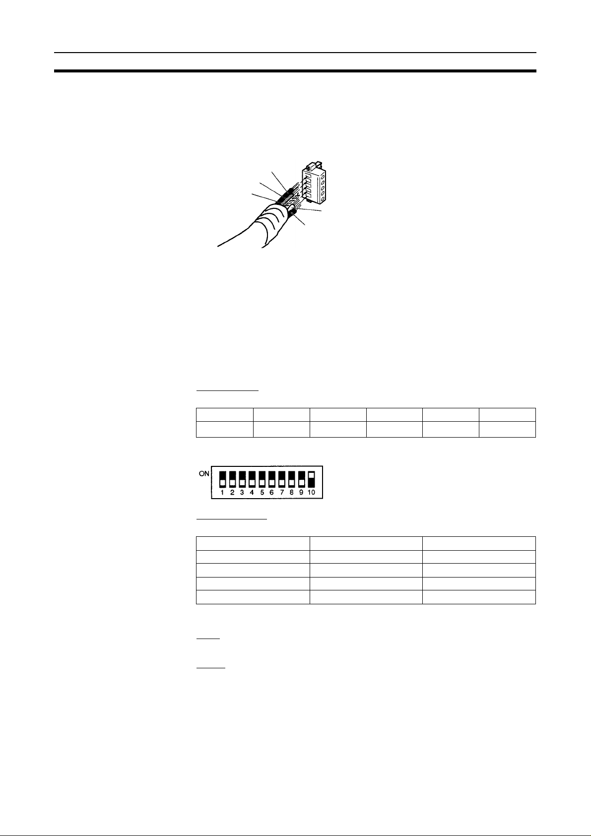
2-1 Cable Connections
Wire the DeviceNet co nnector as s hown in the following diagram. For details
on connecting the Mast er Unit to the E5ZE, refer to the D eviceNet (Compo-
Bus/D) Operation Manual ( Cat. No. W267). Multi
-drop connectors cann ot be
used to connect the E5ZE to the CompoBus/D Master Unit.
Black (-V)
Blue (CAN low)
Shield
White (CAN high)
Red (+V)
2-2 Communications Parameters
Be sure to set the following parameters.
• Node Address
Make sure that the E5ZE node addres s sett ing s and w ords allo ca ted to the
E5ZE are not the same as those set for any other Slave.
•
Baud Rate
Set the same baud rate on the E5ZE and DeviceNet Master Unit.
DeviceNet DIP Switch
Pin 1 to Pin 6
The node address is set using pins 1 to 6.
Pin 1 Pin 2 Pin 3 Pin 4 Pin 5 Pin 6
0
2
Pins 1 to 6 are all factory
1
2
2
2
3
2
4
2
5
2
-set to OFF (node address 00).
Pin 7 and Pin 8
The baud rate is set using pins 7 and 8.
Baud rate Pin 7 Pin 8
125 kbps OFF OFF
250 kbps ON OFF
500 kbps OFF ON
Not used ON ON
Pins 7 and 8 are both factory
-set to OFF (baud rate of 125 kbps).
Pin 9
Always set pin 9 to OFF.
Pin 10
When a DeviceNet communicatio ns error occurs, set th e E5ZE operation as
follows:
ON
Temperature control will continue accor ding to the data that was transmitted immediately before the error occurred.
OFF
Operation is stopped. (Pin 10 is set to ON at the factory.)
6

Communications Parameters Section 2-2
DeviceNet Communications Error
A DeviceNet communications error indic ates a transmission data error or a
connection time
-out error between the DeviceNet Master Unit and the E5ZE.
7

SECTION 3
Remote I/O Communications
This section provides details on remote I/O communicatio ns, including allocations in the PC, various operating statuses,
flags, and applications.
3-1 Transmission Contents and Word Allocations . . . . . . . . . . . . . . . . . . . . . . . . 10
3-2 Reading Process Values . . . . . . . . . . . . . . . . . . . . . . . . . . . . . . . . . . . . . . . . . 10
3-3 Reading Status. . . . . . . . . . . . . . . . . . . . . . . . . . . . . . . . . . . . . . . . . . . . . . . . . 11
3-3-1 Alarm Status . . . . . . . . . . . . . . . . . . . . . . . . . . . . . . . . . . . . . . . . . . . 11
3-3-2 Auto-tuning Status . . . . . . . . . . . . . . . . . . . . . . . . . . . . . . . . . . . . . . 11
3-3-3 Operating Status . . . . . . . . . . . . . . . . . . . . . . . . . . . . . . . . . . . . . . . . 12
3-4 Temperature Control Start/Stop . . . . . . . . . . . . . . . . . . . . . . . . . . . . . . . . . . . 13
3-4-1 Startup Operation . . . . . . . . . . . . . . . . . . . . . . . . . . . . . . . . . . . . . . . 13
3-4-2 Manual Operation. . . . . . . . . . . . . . . . . . . . . . . . . . . . . . . . . . . . . . . 14
3-5 Writing Set Points. . . . . . . . . . . . . . . . . . . . . . . . . . . . . . . . . . . . . . . . . . . . . . 14
3-6 Remote I/O Delay Time . . . . . . . . . . . . . . . . . . . . . . . . . . . . . . . . . . . . . . . . . 15
9

Transmission Contents and Word Allocations Section 3-1
3-1 Transmission Contents and Word Allocations
When remote I/O c ommunications are used with the E5ZE, readi ng the process value, star ting and stoppin g temperature control, and writing s et points
are possible for any control point, without requiring a s pecial program to be
executed from the Master Unit. Data is autom atically ref reshed at every 200
ms cycle. There are 14 input words and 9 output words allocated to the E5ZE
in the Master Unit (I/O directions are in r eference to the Master Unit). Each
word is allocated according to the following table.
Inputs Outputs
First word Control point 0 process value First word Control point 0 set point
+ 1 Control point 1 process value + 1 Control point 1 set point
+ 2 Control point 2 process value + 2 Control point 2 set point
+ 3 Control point 3 process value + 3 Control point 3 set point
+ 4 Control point 4 process value + 4 Control point 4 set point
+ 5 Control point 5 process value + 5 Control point 5 set point
+ 6 Control point 6 process value + 6 Control point 6 set point
+ 7 Control point 7 process value + 7 Control point 7 set point
+ 8 Alarm 1 status + 8 Start/stop temperature
control
+ 9 Alarm 2 status --+ 10 Auto-tuning status
+ 11 HB (heater burnout) alarm sta-
tus
+ 12 HS (SSR failure) alarm status
+ 13 Operating status
-
The first input and output words are normally determined according to the
Master Unit being used and the node address. The first I/O words can be
changed and a Configurator is used to change the Master Unit settings.
3-2 Reading Process Values
The process value for each control point is expressed as 16 -bit s igned bin ar y
data (two
cated in the Master Unit mou nted to the PC. The unit used depends on the
position of the deci mal point in the E5ZE. T he default values are 1
thermocouples and 0.1
Leftmost bit Rightmost bit
Example
If the setting unit is 0.1°C/°F, and the value in the allocated word is
1111110001111100, the conversion values are as follows:
Binary Hexadecimal Decimal Process value
1111110001111100 FC7C -900 -90.0
If the value in the word is 0000010001001100, the values are as follows:
Binary Hexadecimal Decimal Process value
0000010001001100 044C 1100 110.0
’s complement for negative values) in the correspon ding word allo-
°C/°F for
°C/°F for platinum resistance thermometers.
°C
°C
10

Reading Status Section 3-3
The following table shows the values that will be contained in th e co rres po nding word under certain conditions.
Status details Value (hexadecimal)
Process value overflow or input error 7FFF
Process value underflow 8000
Temperature Controller error or connec-
tion confirmation standb y
Outside temperature display range 7D00
0000 or the last value sent
3-3 Reading Status
3-3-1 Alarm Status
Alarms 1 and 2, HB and HS Alarms
The alarm status is expressed in the corr esponding word in the PC to which
the Master Unit is connected as shown in the following diagram. The format is
the same for the alarm 1, alar m 2, HB (h eater burnout ) alar m, and HS (SS R
failure) alarm.
Alarm Status
This bit will change from 0 to 1 when an
alarm is ON for any control point.
Example
If the alarm 1 is OFF for all con trol poin ts and then t ur ns ON for contr ol point
3, the contents of the corresponding word in the PC will change as follows:
0000000000000000 ® 1000000000001000
When alarm 1 turns OFF for control point 3, the contents of the corresponding
word will return to 0000000000000000.
3-3-2 Auto-tuning Status
The auto-tuning status is reflected in the corresponding word in the PC to
which the Master Unit is mounted.
Leftmost bit Rightmost bit
0000000 (fixed) Alarm status for control points 0 to 7
Auto-tuning Status
(The bit corresponding to the control
point for which the alarm is ON will
change from 0 to 1.)
Alarm 1 ON for
control point 3
Leftmost bit Rightmost bit
0000000 (fixed) Auto-tuning status for control points 0 to 7
This bit will change from 0 to 1 when
any control point is being auto-tuned.
(The bits corresponding to the control
points that are being auto-tuned will
change from 0 to 1.)
11
Reading Status Section 3-3
Example
If no control points are being auto-tuned, and then auto-tuning begins for control point 3, the contents of the corresponding word in the PC wil l change as
follows:
0000000000000000 ® 1000000000001000
Control point 3 is
being auto-tuned.
When auto
corresponding word will return to 0000000000000000.
3-3-3 Operating Status
The status data showing whether an error has occurred in the E5ZE is
expressed in the contents of the correspondin g word in the PC to which the
Master Unit is mounted.
Operating status
Leftmost bit Rightmost bit
Outside T emperature
Display Range Flag
This bit changes from 0 to 1
if any of bits 0 to 8 changes
from 0 to 1.
Temperature Controller Ready Flag
The following table provides the m eaning and operation of the operating status flags.
Temperature Controller
Ready Flag
Outside Temperature Display Range Flag
Output Area Error Flag (See
note 1.)
Temperature Control Internal
T r ansmission Error Fl ag (See
note 1.)
Temperature Controller Error
Flag
Input Error Flag This flag changes from 0 to 1 if the temperature sen-
Process Value Overflow Flag This flag changes from 0 to 1 if the process value is
-tuning for control point 3 has been c omple ted, the co ntents of the
Heater Current Overflow Flag
Process Value Underflow Flag
Process Value Overflow Flag
Input Error Flag
Temperature Controller Error Flag
Temperature Control Internal Transmission Error Flag
Output Area Error Flag
Flag name Meaning
This flag changes from 0 to 1 when the E5ZE pow er is
turned ON and DeviceNet communications are
enabled.
After checking that this flag is ON, execute the program to start using I/O data.
This flag changes from 0 to 1 if the process value
exceeds 3200.0°F when a W/Re5-26 thermocouple
sensor is being used and the setting unit is 0.1°C/°F.
This flag changes from 0 to 1 if the output data from
the Master is not reflected in the E5ZE due to the
operating mode.
This flag changes from 0 to 1 if the remote I/O function has not been processed properly in the E5ZE.
This flag changes from 0 to 1 if there i s an error in the
Temperature Controller , su ch as an AD con verter
error or memory error.
sor is disconnected or short-circuited.
more than the maximum value of the setting range.
(See note 2.)
12
Temperature Control Start/Stop Section 3-4
Flag name Meaning
Process Value Underflow
Flag
Heater Current Overflow Flag This flag changes from 0 to 1 if the measured heater
This flag changes from 0 to 1 if the process value is
less than the minimum value of the setting range.
(See note 2.)
current exceeds 55.0 A when the HB and HS alarm
are being used.
Note 1. If the Output Area Er ror Flag or Te mperature Controller Err or Flag is ON
(1) for longer than 1 s, the remote I/O data will not be transmitted correctly
to the E5ZE.
2. The measurement range is from the setting range lower
ue (-20
40
°C or -40°F) to the setting range upper-limit positive value (20°C or
°F).
-limit negative val-
3-4 Temperature Control Start/Stop
The temperature contr ol of control po ints in the E 5ZE is star ted and stopped
by operating the bits in the corresponding word al located in the PC to which
the Master Unit is mounted, as follows:
Temperature Control Start/Stop
Leftmost bit Rightmost bit
Example
If the temperature contr ol of all control points is stopped and then star ts for
control point 3, the contents of the corre spond ing word in the PC will chang e,
as follows:
0000000000000000 ® 0000000000001000
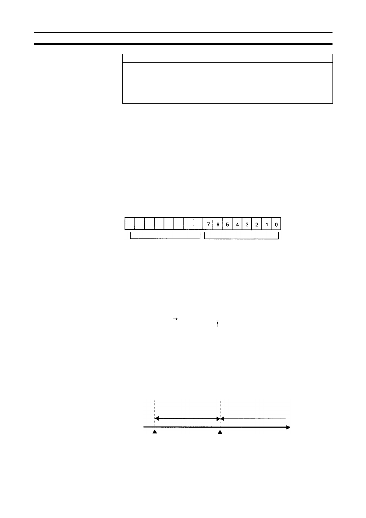
3-4-1 Startup Operation
When pin 5 (star tup operation setting) of the FUNCTION switch on the fron t
panel of the E5ZE
ON, the Unit will operate as shown in the following diagram.
E5ZE status
Set to 00000000 Set the bits corresponding to the
control points for which temperature
control is to begin to 1.
To stop temperature control for any
control point, set the corresponding
bit to 0.
Temperature control
started for control
point 3
-8@@@D1@B-V2 Multipoint Temperature Controller is set to
Operation according to
control temperature and
operating status when
power was turned OFF
previously.
Operation according to control temperature
and operating status set by remote I/O.
E5ZE
power ON
DeviceNet communications
between Master and E5ZE
enabled.
Time
13

Writing Set Points Section 3-5
The time required for DeviceNet communicatio ns to be enabled will depend
on the order in which power is supplied, the number of Slaves connected to
the Master, the baud rate, and other variables.
3-4-2 Manual Operation
When the E5ZE-8@@@D1@B-V2 Multi point Temperature Controller is being
operated manually, the following procedure is required depending on the relationship to the remote I/O Temperature Control Start/Stop Bit.
Refer to page 28 for details on the rela tionship between remote I/O and the
E5ZE operating status.
Starting Manual Operation
1,2,3... 1. Se t the Temperature Control Start/Stop Bi t to 1 for the control point to be
manually operated and temperature control will start for the control point.
2. Execute the Manual Operation Star t command using DeviceNet explicit
Stopping Manual Operation
message communica tions or through the RS
Manual operation will start.
3. Set the manual output using DeviceNet explicit message communications
or through the RS
Set the Temperature Control Star t/Stop Bit to 0 for the control point being
manually operated and tempe rature control will stop for the specified control
point. Temperature control can then be restarted by setting the bit to 1 again.
-232C auxiliary setting jack.
-232C auxiliary setting jack.
3-5 Writing Set Points
The set point for each control point is written as 16-bit signed binary data
’s complement for negative values) in the correspondin g word in the PC
(two
to which the Master Unit is mounted. The value is automatically transmitted to
the E5ZE. The data w ill be written acc ording to the setting unit that is set i n
the E5ZE. The default value is 1
inum resistance ther mo mete r s.
Leftmost bit Rightmost bit
Example
If the set point is to be set to -90.0°C, and the setting unit is 0.1°C, the value
set in the corresponding word will be as follows:
Set Point Decimal Hexadecimal Binary
°C -900 FC7C 1111110001111100
-90.0
If the set point is to b e set to 11 0.0
set in the corresponding word will be as follows:
Set Point Decimal Hexadecimal Binary
°C 1100 044C 0000010001001100
110.0
If the set point is to be set to 110.0
in the corresponding word will be as follows:
Set Point Decimal Hexadecimal Binary
°C 110 006E 0000000001101110
110.0
Refer to page 25 for details on the permissible setting ranges.
°C/°F for thermocouples and 0.1°C/°F for plat-
°C, and the setting unit is 0.1°C, the value
°C, and the setting unit is 1°C, the value set
14

Remote I/O Delay Time Section 3-6
3-6 Remote I/O Delay Time
• The time required for the remot e I/O d ata reflec ti ng th e changed data to be
prepared at the E5ZE after a main i npu t to th e E 5Z E has ch ang ed i s cal le d
the input delay time.
• The time required fo r the da ta that has b een transmitted to the E 5ZE us in g
DeviceNet communicati ons to affect in the operation of the E5ZE is called
the output delay time.
• The maximum input and output delay times are 500 ms.
• For details on how to calculate the I/O delay time, refer to the DeviceNet
(CompoBus/D) Operation Manual (Cat. No. W267).
15

SECTION 4
DeviceNet Explicit Message Communications
DeviceNet explicit message communi cations are used to read and write the E5 ZE’s measurement values and set v alues that
cannot be read or written using remote I/O communications. Settings can also be made from a master not manufactured by
OMRON.
Parameters written using DeviceNet explicit messages are saved even if the power supply is turned OFF.
This section provides details on DeviceNet explicit messages, including command and response formats, the instructions
used by the PC to execute DeviceNet explicit message communications, and tables of set values and measurement values
showing setting ranges, default values, data types, and addresses.
4-1 Transmitting DeviceNet Explicit Messages . . . . . . . . . . . . . . . . . . . . . . . . . . 18
4-1-1 Command Format. . . . . . . . . . . . . . . . . . . . . . . . . . . . . . . . . . . . . . . 18
4-1-2 Commands . . . . . . . . . . . . . . . . . . . . . . . . . . . . . . . . . . . . . . . . . . . . 19
4-1-3 Remote I/O and DeviceNet Explicit Messages. . . . . . . . . . . . . . . . . 19
4-2 E5ZE Fixed Command Configuration . . . . . . . . . . . . . . . . . . . . . . . . . . . . . . 19
4-3 Instruction Execution Precautions. . . . . . . . . . . . . . . . . . . . . . . . . . . . . . . . . . 20
4-3-1 CMND(194/490): CVM1, CV-series, and CS1-series PCs . . . . . . . 20
4-3-2 IOWR(223): C200HX/C200HE/C200HG PCs . . . . . . . . . . . . . . . . 20
4-3-3 Control Data for Sending DeviceNet Explicit Messages Using
4-4 DeviceNet Explicit Messages Set Values and Measurement Values . . . . . . . 21
4-4-1 Commonly Used Set Values . . . . . . . . . . . . . . . . . . . . . . . . . . . . . . . 21
4-4-2 Reading/Writing using Variable Type 90 . . . . . . . . . . . . . . . . . . . . . 27
4-4-3 Operation Variables . . . . . . . . . . . . . . . . . . . . . . . . . . . . . . . . . . . . . 27
4-4-4 Relationship between Operating Status and Operating Commands. 28
4-4-5 Set Values in Memory Banks . . . . . . . . . . . . . . . . . . . . . . . . . . . . . . 28
4-4-6 Measurement Values for Individual Control Points . . . . . . . . . . . . . 30
4-4-7 Set Values for all Control Points. . . . . . . . . . . . . . . . . . . . . . . . . . . . 31
4-4-8 Set Values for All Control Points . . . . . . . . . . . . . . . . . . . . . . . . . . . 32
CMND(194/490) or IOWR(223) . . . . . . . . . . . . . . . . . . . . . . . . . . . 21
17
Transmitting DeviceNet Explicit Messages Section 4-1
4-1 Transmitting DeviceNet Explicit Messages
DeviceNet explicit messages are executed from the user program using the
CMND(194/490) instruction for a CVM1, CV
the IOWR(223) instruction with a C200HX, C200HG, or C200HE PC.
The transmission proced ure involves the Master sending a command to the
E5ZE and the E5ZE returning a response to the command back to the Master.
-series, or CS1-series PC, and
Master Unit
E5ZE
Refer to the DeviceNet (CompoBus/D) Operation Manual (Cat. No. W267) for
details on the transmission methods.
Details on the format of commands and responses used for transmission, and
the set values and measurem ent values specific to the E5ZE are provided
here.
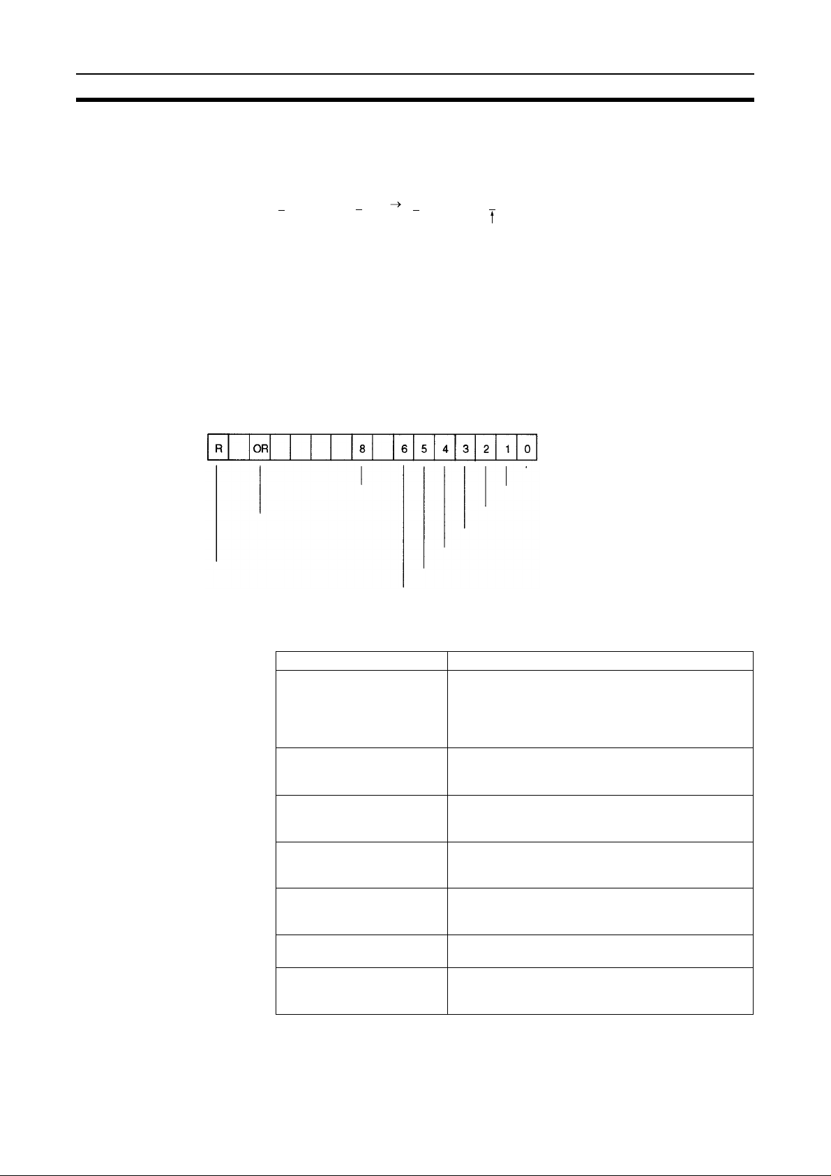
4-1-1 Command Format
The command format for DeviceNet explicit messages is given below.
Command
Command
Service code Instance ID
Destination
node address
Class ID
Command
Response
Command
code
E5ZE fixed command (Refer to 4-2 E5ZE
Fixed Command Configuration
Parameter
.)
Response
Normal
Error
Service code
Destination
node address
Service code
Destination
node address
Command
code
E5ZE fixed response (Refer to
Fixed Command Configuration
DeviceNet
error code
End code
4-2 E5ZE
.)
18
E5ZE Fixed Command Configuration Section 4-2
4-1-2 Commands
There are only two commands that can be used with the E5ZE.
Command type Command code
MEMORY AREA READ 0101
MEMORY AREA WRITE 0102
4-1-3 Remote I/O and DeviceNet Explicit Messages
Data written with the remote I/O allocated in the DeviceNet Network is
updated in the E5ZE every 200 ms. Data wr itten with DeviceNet explicit messages is updated when the command is executed.
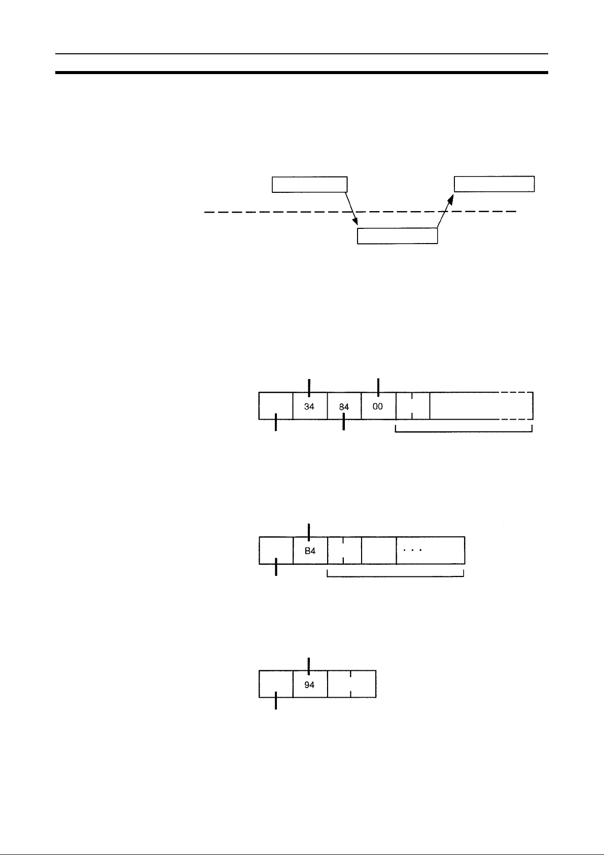
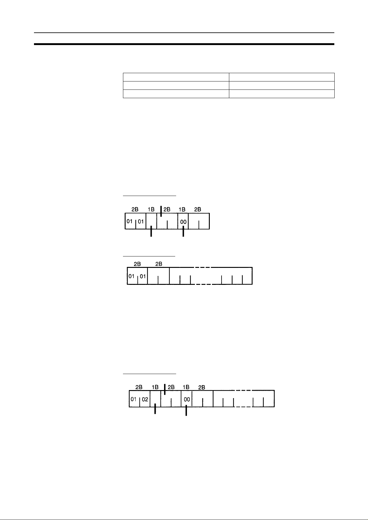
4-2 E5ZE Fixed Command Configuration
Reading PC Memory
The following diagram shows the format of command data and re sp ons e dat a
when messages are used to read set values and measurem ent values from
the E5ZE to which the Master Unit is mounted.
Command Format
First read address
Writing PC Memor y
Command
code
Variable type Bit position
Number of read data elements
Response Format
Read data
Command
code
End code
• The total number of read data bytes is 2 × Number of read data elemen ts.
• Refer to the table of DeviceNet expli cit mes s age s s et valu es and m eas urement values for details on addresses and variable types for read set values
and measurement values.
The following diagram shows the format of command data and re sp ons e dat a
when messages are u sed to write set values an d measurement values from
the E5ZE to which the Master Unit is mounted.
Command Format
First write address
Write data
Command
code
Variable type Bit position
Number of write data elements
19

Instruction Execution Precautions Section 4-3
Response Format
Command
code
End code
• The total number of write data bytes is 2 × Number of write data elements.
• Refer to the table of DeviceNet expli cit mes s age s s et valu es and m eas urement values for d etails o n addr e sses a nd va riabl e ty pes of write set val ues
and measurement values.
• If there is an error in even one part of the data being writ ten, all o f the data
written at the same time will not be saved in the E5ZE.
FINS command 2801 is sent using CMND(194/490) or IOWR(223) to s end
DeviceNet explicit messages from an OMRON PC Master Unit. For details,
refer to the DeviceNet (CompoBus/D ) Operation Manual (Cat. No. W267) or
the CS1W
-DRM21 DeviceNet Unit Operation Manual (Cat. No. W380).
4-3 Instruction Execution Precautions
When DeviceNet explicit messag e communications are us ed with the E5ZE,
there are settings that are specific to the control data for CMND(194/490) and
IOWR(223) instructions that must be set, as shown next.
For details on both inst ructions and their applicati ons, refer to the DeviceNet
(CompoBus/D) Operation Manual (Cat. No. W267).
4-3-1 CMND(194/490): CVM1, CV-series, and CS1-series PCs
The control data for the CMND(194/490) instructions is as follows:
Word Bit
15 12 11 08 07 06 05 04 03 00
C Number of command data bytes
C+1 Number of response data bytes
C+2 0 0 Des ti nati on net w o rk address
C+3 Destination node address
(Local node DeviceNet Master
MAC ID)
C+4 0 (response
required)
C+5 Response monitoring time (0000 to FFFF), in 0.1 s incre ments (e xcept 0000
that is 2 s)
Communications port No.
(0 to 7)
Destination unit address
(Local node De vi ceNet Master Special
I/O Unit number or FE)
0 Number of
retries (0 to F)
4-3-2 IOWR(223): C200HX/C200HG/C200HE PCs
The control data for the IOWR(223) instruction is as follows:
Word Bit
15 08 07 00
C 0/1 0 Destination address
(Local node DeviceNet
Master MAC ID)
Bit 15 is used to set whether a response is required or not. If bit 15 is set to 0,
a response is required and if the bit is set to 1, a response is not required. Set
this bit to 0 (response required).
Bits 8 to 13 are used to set the destination node address (E5ZE node
address), and bits 0 to 7 are used to set the destination Unit address (the local
node DeviceNet Master Special I/O Unit number or FE).
20
Destination unit address

DeviceNet Explicit Messages Set Values and Measurement Section 4-4
4-3-3 Control Data for Sending DeviceNet Explicit Messages Using
CMND(194/490) or IOWR(223)
Master Unit
Unit No. 2
IOWR(223) control data
PC
Destination
node address
CMND(194/490) control data
No. of command data bytes
Destination Unit address FE or 12
(12 indicates Special I/O Unit No. 2)
Explicit message
Destination node address
No. of response data types
Send to local network
Destination Unit address FE or 12
(12 indicates Special I/O Unit No. 2)
Resend once
4-4 DeviceNet Explicit Messages Set V alues and Measurement
Values
This section provides tables that can be used when setting and monitoring the
set values for all control points. The tables are given by variable type.
4-4-1 Commonly Used Set Values
Variable Type: 90
No. Address Set value or measurement value Data setting or monitoring range Data type
1 0000 Control point 0 process value Range: Depends on sensor type used.
2 0001 Control point 1 process value
3 0002 Control point 2 process value
4 0003 Control point 3 process value
5 0004 Control point 4 process value
6 0005 Control point 5 process value
7 0006 Control point 6 process value
8 0007 Control point 7 process value
(See note 4.)
Unit:Depends on s etting (e ither 0.1°C/°F or
1°C/°F)
Numeric
Read only
9 000C Alarm 1 status Range: 0000 to 80FF Status
10 000D Alarm 2 status Range: 0000 to 80FF
11 000E Auto–tuning status Range: 0000 to 80FF
12 000F HB alarm status Range: 0000 to 80FF
13 0010 HS alarm status Range: 0000 to 80FF
Read only
Bit contents same
as remote I/O
contents.
21

DeviceNet Explicit Messages Set Values and Measureme nt Section 4-4
No. Address Set value or measurement value Data setting or monitoring range Data type
14 0011 Temperature control status
(See note 7.)
15 0012 Operation start/stop
(See notes 3 and 6.)
16 0013 Control point 0 set point Range: Depends on sensor type used.
17 0014 Control point 1 set point
18 0015 Control point 2 set point
19 0016 Control point 3 set point
20 0017 Control point 4 set point
21 0018 Control point 5 set point
22 0019 Control point 6 set point
23 001A Control point 7 set point
Range: 0000 to 811F Status
Read only
Range: 0000 to 00FF (Default: 0000) Status
Read
Numeric
(See notes 1 and 4.)
Unit: Depends on setting (either 0.1°C/
°F or 1°C/°F)
Read
24 001F Auto-tuning start/stop
(See note 2.)
25 0020 Control point 0 alarm 1 temperature Range: D8F1 to 7350 (-999.9 to 3000.0)
26 0021 Control point 1 alarm 1 temperature
27 0022 Control point 2 alarm 1 temperature
28 0023 Control point 3 alarm 1 temperature
29 0024 Control point 4 alarm 1 temperature
30 0025 Control point 5 alarm 1 temperature
31 0026 Control point 6 alarm 1 temperature
32 0027 Control point 7 alarm 1 temperature
33 002C Control point 0 alarm 2 temperature Range: D8F1 to 7530 (-999.9 to 3000.0)
34 002D Control point 1 alarm 2 temperature
35 002E Control point 2 alarm 2 temperature
36 002F Control point 3 alarm 2 temperature
37 0030 Control point 4 alarm 2 temperature
38 0031 Control point 5 alarm 2 temperature
39 0032 Control point 6 alarm 2 temperature
40 0033 Control point 7 alarm 2 temperature
41 0038 Control point 0 input shift value Range: FC19 to 03E7 (-99.9 to 99.9)
42 0039 Control point 1 input shift value
43 003A Control point 2 input shift value
44 003B Control point 3 input shift value
45 003C Control point 4 input shift value
46 003D Control point 5 input shift value
47 003E Control point 6 input shift value
48 003F Control point 7 input shift value
Range: 0000 to 00FF
Default: 0000
when setting unit is 0.1°C/°F. (See note 4.)
Range: D8F1 to 270F (-9999 to 9999)
when setting unit is 1°C/°F.
Default: 0000 (0.0 or 0)
when setting unit is 0.1°C/°F. (See note 4.)
Range: D8F1 to 270F (-9999 to 9999)
when setting unit is 1°C/°F.
Default: 0000 (0.0 or 0)
(See note 1.)
Unit: 0.1°C or °F
Default: 0000 (0.0)
Status
Write only
Numeric
Read/write
Numeric
Read/write
Numeric
Read/write
22

DeviceNet Explicit Messages Set Values and Measurement Section 4-4
No. Address Set value or measurement value Data setting or monitoring range Data type
49 0044 Control point 0 proportional band Range: 0000 to 270F (0.0 to 999.9)
50 0045 Control point 1 proportional band
51 0046 Control point 2 proportional band
52 0047 Control point 3 proportional band
53 0048 Control point 4 proportional band
54 0049 Control point 5 proportional band
55 004A Control point 6 proportional band
56 004B Control point 7 proportional band
(See note 1.)
Unit: 0.1°C or °F
Default: 0000 (0.0)
Numeric
Read/write
57 0050 Control point 0 integral time Range: 0000 to 0F9F (0 to 3999)
58 0051 Control point 1 integral time
59 0052 Control point 2 integral time
60 0053 Control point 3 integral time
61 0054 Control point 4 integral time
62 0055 Control point 5 integral time
63 0056 Control point 6 integral time
64 0057 Control point 7 integral time
65 005C Control point 0 derivative time Range: 0000 to 0F9F (0 to 3999)
66 005D Control point 1 derivative time
67 005E Control point 2 derivative time
68 005F Control point 3 derivative time
69 0060 Control point 4 derivative time
70 0061 Control point 5 derivative time
71 0062 Control point 6 derivative time
72 0063 Control point 7 derivative time
73 0068 Control point 0 heating output vari-
able
74 0069 Control point 1 heating output vari-
able
75 006A Control point 2 heating output vari-
able
76 006B Control point 3 heating output vari-
able
77 006C Control point 4 heating output vari-
able
78 006D Control point 5 heating output vari-
able
79 006E Control point 6 heating output vari-
able
80 006F Control point 7 heating output vari-
able
(See note 1.)
Unit: 1 s
Default: 0000 (0)
(See note 1.)
Unit: 1 s
Default: 0000 (0)
Range: 0000 to 03EB (0.0 to 100.0)
Unit: 0.1%
Numeric
Read/write
Numeric
Read/write
Numeric
Read only
23

DeviceNet Explicit Messages Set Values and Measureme nt Section 4-4
No. Address Set value or measurement value Data setting or monitoring range Data type
81 0074 Control point 0 heater current Range: 0000 to 0226 (0.0 to 55.0)
82 0075 Control point 1 heater current
83 0076 Control point 2 heater current
84 0077 Control point 3 heater current
85 0078 Control point 4 heater current
86 0079 Control point 5 heater current
87 007A Control point 6 heater current
88 007B Control point 7 heater current
(See note 8.)
Unit: 0.1 A
Numeric
Read only
89 0080 Control point 0 memory bank No. Range: 0000 to 0007
90 0081 Control point 1 memory bank No.
91 0082 Control point 2 memory bank No.
92 0083 Control point 3 memory bank No.
93 0084 Control point 4 memory bank No.
94 0085 Control point 5 memory bank No.
95 0086 Control point 6 memory bank No.
96 0087 Control point 7 memory bank No.
97 008C Control point 0 heater burnout
detection current
98 008D Control point 1 heater burnout
detection current
99 008E Control point 2 heater burnout
detection current
100 008F Control point 3 heater burnout
detection current
101 0090 Control point 4 heater burnout
detection current
102 0091 Control point 5 heater burnout
detection current
103 0092 Control point 6 heater burnout
detection current
104 0093 Control point 7 heater burnout
detection current
(See note 1.)
Default: 0000 (0)
Range: 0000 to 01F4 (0.0 to 50.0)
Unit: 0.1 A
Default: 0000 (0.0)
Numeric
Read/write
Numeric
Read/write
105 0098 Control point 0 cooling coefficient Range: 0000 to 0064 (0.0 to 10.0)
106 0099 Control point 1 cooling coefficient
107 009A Control point 2 cooling coefficient
108 009B Control point 3 cooling coefficient
109 009C Control point 4 cooling coefficient
110 009D Control point 5 cooling coefficient
111 009E Control point 6 cooling coefficient
112 009F Control point 7 cooling coefficient
(See note 1.)
Unit: 0.1
Default: 000A (1.0)
24
Numeric
Read/write

DeviceNet Explicit Messages Set Values and Measurement Section 4-4
No. Address Set value or measurement value Data setting or monitoring range Data type
113 00A4 Control point 0 dead band Range: FC19 to 03E7 (-999 to 999)
114 00A5 Control point 1 dead band
115 00A6 Control point 2 dead band
116 00A7 Control point 3 dead band
117 00A8 Control point 4 dead band
118 00A9 Control point 5 dead band
119 00AA Control point 6 dead band
120 00AB Control point 7 dead band
(See note 1.)
Unit: 1°C or °F
Default: 0000 (0)
Numeric
Read/write
121 00B0 Control point 0 fuzzy strength Range: 0000 to 0063 (0 to 99)
122 00B1 Control point 1 fuzzy strength
123 00B2 Control point 2 fuzzy strength
124 00B3 Control point 3 fuzzy strength
125 00B4 Control point 4 fuzzy strength
126 00B5 Control point 5 fuzzy strength
127 00B6 Control point 6 fuzzy strength
128 00B7 Control point 7 fuzzy strength
(See note 1.)
Unit: 1%
Default: 0032 (50)
Numeric data for the values in the above table is all expressed as 16-bit
signed binary (two
’s complement for negative values)
Note 1. Numeric data cannot be modified during auto
2. Auto
-tuning cannot be executed when operation is sto pped. The sequ en-
tial auto
-tuning function is not supported with DeviceNet communications.
3. If an instruction to stop operation is executed during auto
will stop after auto
-tuning is cancelled.
4. The setting ranges var y depending o n the setting unit used, as show n in
the following table.
Temperature
sensor
°C °F °C °F
K FF38 to 0514
(-200 to 1300)
J FF9C to 0352
(-100 to 850)
R 0000 to 06A4
(0 to 1700)
S 0000 to 06A4
(0 to 1700)
T FF38 to 0190
(-200 to 400)
E 0000 to 0258
(0 to 600)
B 0064 to 0708
(100 to 1800)
N 0000 to 0514
(0 to 1200)
L FF9C to 0352
(-100 to 850)
U FF38 to 0190
(-200 to 400)
W/Re5-26 0000 to 08FC
(0 to 2300)
Setting unit (1) Setting unit (0.1)
FED4 to 08FC
(-300 to 2300)
FF9C to 05DC
(-100 to 1500)
0000 to 0BB8
(0 to 3000)
0000 to 0BB8
(0 to 3000)
FED4 to 02BC
(-200 to 700)
0000 to 044C
(0 to 1100)
012C to 0BB8
(300 to 3000)
0000 to 08FC
(0 to 2300)
FF9C to 05DC
(-100 to 1500)
FED4 to 02BC
(-300 to 700)
0020 to 1004
(0 to 4100)
Setting range
F830 to 32C8
(-200.0 to 1300.0)
FC18 to 2134
(-100.0 to 850.0)
0000 to 4268
(0.0 to 1700.0)
0000 to 4268
(0.0 to 1700.0)
F830 to 0FA0
(-200.0 to 400.0)
0000 to 1770
(0.0 to 600.0)
03E8 to 4650
(100.0 to 1800.0)
0000 to 32C8
(0.0 to 1300.0)
FC18 to 2134
(-100.0 to 850.0)
F830 to 0FA0
(-200.0 to 400.0)
0000 to 59D8
(0.0 to 2300.0)
Numeric
Read/write
-tuning.
-tuning, operation
F448 to 59D8
(-300.0 to 2300.0)
FC18 to 3A98
(-100.0 to 1500.0)
0000 to 7530
(0.0 to 3000.0)
0000 to 7530
(0.0 to 3000.0)
F448 to 1B58
(-300.0 to 700.0)
0000 to 2AF8
(0.0 to 1100.0)
0BB8 to 7530
(300.0 to 3000.0)
0000 to 59D8
(0.0 to 2300.0)
FC18 to 3A98
(-100.0 to 1500.0)
F448 to 1B58
(-300.0 to 700.0)
0140 to 7D00
(32 to 3200.0)
25

DeviceNet Explicit Messages Set Values and Measureme nt Section 4-4
Temperature
sensor
°C °F °C °F
PL II 0000 to 0514
Pt FF9C to 01F4
JPt FF9C to 01F4
Alarm setting
range
(0 to 1300)
(-100 to 500)
(-100 to 500)
D8F1 to 270F (-9999 to 9999) D8F1 to 7530 (-999.9 to 3000.0)
Setting range
Setting unit (1) Setting unit (0.1)
0000 to 08FC
(0 to 2300)
FF9C to 0384
(-100 to 900)
FF9C to 0384
(-100 to 900)
0000 to 32C8
(0.0 to 1300.0)
FC18 to 1388
(-100.0 to 500.0)
FC18 to 1388
(-100.0 to 500.0)
0000 to 59D8
(0.0 to 2300.0)
FC18 to 2328
(-100.0 to 900.0)
FC18 to 2328
(-100.0 to 900.0)
• If an E5ZD-SDL Setting Display Unit is used with the E5ZE, and the setting
unit is 0.1
°C/°F, the setting range will be l imited to F8 31 to 270F (-19 9.9 to
999.9).
• If the alarm temperature that is read is more than 7530 (Hex), the temperature will be read as 7FFF (H ex), and if the alarm temper ature is less than
D8F1 (Hex), then the temperature will be read as 8000 (Hex).
5. The meaning of the Auto-tuning Start/Stop Bits is as follows:
Auto-tuning Start/Stop
Leftmost bit Rightmost bit
Set bits 8 to 15 to 00000000. Set the bits corresponding to the control points
to be auto-tuned to 1 and then write the data.
To stop auto-tuning, set the bits corresponding
to the control points to be stopped to 0 and
then write the data.
6. The contents of the Operation Start/Stop Bit is the same as that for the re-
mote I/O, as shown here.
Read: 0: Operation stopped.
1: Controlling temperature or operating manually.
Write: 0: Stop operation.
1: Start or continue temperature control or continue manual operation. (Even if 1 is written to a control po int that is being operated
manually it will not start temperature control.)
7. The meaning of the operating status bits is as follows:
Operating Status
Leftmost bit Rightmost bit
Outside T emperature
Display Range Flag
Changes from 0 to 1 if any
bit is set to 1.
Temperature Controller Error Flag
Temperature Control Internal Transmission Error Flag
Reserved for the system
Process Value Underflow Flag
Process Value Overflow Flag
Input Error Flag
Heater Current Overflow Flag
26
8. Control points that have been se t to disable the HB and HS alarms, and
control points that are not operating will be read as 0000 (hex).
 Loading...