

Page 1

E5ZE
Multipoint Temperature Controller
Operation Manual
Catalog No. H076-E3-1
Page 2

Notice:
OMRON products are manufactured for use according to proper procedures by a qualified operator
and only for the purposes described in this manual.
The following conventions are used to indicate and classify precautions in this manual. Always heed
the information provided with them. Failure to heed precautions can result in injury to people or damage to property.
DANGER Indicates an imminently hazardous situation which, if not avoided, will result in death or
!
serious injury.
WARNING Indicates a potentially hazardous situation which, if not avoided, could result in death or
!
serious injury.
Caution Indicates a potentially hazardous situation which, if not avoided, may result in minor or
!
moderate injury, or property damage.
OMRON Product References
All OMRON products are capitalized in this manual. The word “Unit” is also capitalized when it refers
to an OMRON product, regardless of whether or not it appears in the proper name of the product.
The abbreviation “Ch,” which appears in some displays and on some OMRON products, often means
“word” and is abbreviated “Wd” in documentation in this sense.
The abbreviation “PC” means Programmable Controller and is not used as an abbreviation for anything else.
Visual Aids
The following headings appear in the left column of the manual to help you locate different types of
information.
OMRON, 1997
All rights reserved. No part of this publication may be reproduced, stored in a retrieval system, or transmitted, in any
form, or by any means, mechanical, electronic, photocopying, recording, or otherwise, without the prior written permission of OMRON.
No patent liability is assumed with respect to the use of the information contained herein. Moreover, because OMRON is
constantly striving to improve its high-quality products, the information contained in this manual is subject to change
without notice. Every precaution has been taken in the preparation of this manual. Nevertheless, OMRON assumes no
responsibility for errors or omissions. Neither is any liability assumed for damages resulting from the use of the information contained in this publication.
Note Indicates information of particular interest for efficient and convenient operation
of the product.
1, 2, 3... 1. Indicates lists of one sort or another, such as procedures, checklists, etc.
v
Page 3

TABLE OF CONTENTS
PRECAUTIONS xi. . . . . . . . . . . . . . . . . . . . . . . . . . . . . . . . .
1 General Safety Precautions xii. . . . . . . . . . . . . . . . . . . . . . . . . . . . . . . . . . . . . . . . . . . . . . . . . . . .
2 Operating Environment Precautions xii. . . . . . . . . . . . . . . . . . . . . . . . . . . . . . . . . . . . . . . . . . . . .
3 Application Precautions xii. . . . . . . . . . . . . . . . . . . . . . . . . . . . . . . . . . . . . . . . . . . . . . . . . . . . . .
SECTION 1
Introduction 1. . . . . . . . . . . . . . . . . . . . . . . . . . . . . . . . . . . .
1-1 Component Names and Functions 2. . . . . . . . . . . . . . . . . . . . . . . . . . . . . . . . . . . . . . . . . . .
1-2 System Configuration 4. . . . . . . . . . . . . . . . . . . . . . . . . . . . . . . . . . . . . . . . . . . . . . . . . . . . .
1-3 Main Functions 5. . . . . . . . . . . . . . . . . . . . . . . . . . . . . . . . . . . . . . . . . . . . . . . . . . . . . . . . . .
SECTION 2
Preparations 7. . . . . . . . . . . . . . . . . . . . . . . . . . . . . . . . . . . .
2-1 List of Models 8. . . . . . . . . . . . . . . . . . . . . . . . . . . . . . . . . . . . . . . . . . . . . . . . . . . . . . . . . .
2-2 Mounting the Serial Communications Models 10. . . . . . . . . . . . . . . . . . . . . . . . . . . . . . . . .
2-3 Setting Selectors and Switch 12. . . . . . . . . . . . . . . . . . . . . . . . . . . . . . . . . . . . . . . . . . . . . . .
2-4 Installation 15. . . . . . . . . . . . . . . . . . . . . . . . . . . . . . . . . . . . . . . . . . . . . . . . . . . . . . . . . . . . .
2-5 Power Supply and Input Wiring 17. . . . . . . . . . . . . . . . . . . . . . . . . . . . . . . . . . . . . . . . . . . . .
2-6 Wiring CT Inputs and Control/Alarm Outputs 19. . . . . . . . . . . . . . . . . . . . . . . . . . . . . . . . .
2-7 Connecting Communications 24. . . . . . . . . . . . . . . . . . . . . . . . . . . . . . . . . . . . . . . . . . . . . . .
SECTION 3
Functions 29. . . . . . . . . . . . . . . . . . . . . . . . . . . . . . . . . . . . . .
3-1 Data Configuration 30. . . . . . . . . . . . . . . . . . . . . . . . . . . . . . . . . . . . . . . . . . . . . . . . . . . . . . .
3-2 I/O Settings 31. . . . . . . . . . . . . . . . . . . . . . . . . . . . . . . . . . . . . . . . . . . . . . . . . . . . . . . . . . . . .
3-3 Set Point and Process Value 32. . . . . . . . . . . . . . . . . . . . . . . . . . . . . . . . . . . . . . . . . . . . . . . .
3-4 Alarm Output Settings 33. . . . . . . . . . . . . . . . . . . . . . . . . . . . . . . . . . . . . . . . . . . . . . . . . . . .
3-5 Output Limitations 35. . . . . . . . . . . . . . . . . . . . . . . . . . . . . . . . . . . . . . . . . . . . . . . . . . . . . . .
3-6 Ramp 36. . . . . . . . . . . . . . . . . . . . . . . . . . . . . . . . . . . . . . . . . . . . . . . . . . . . . . . . . . . . . . . . .
3-7 Control Adjustments 37. . . . . . . . . . . . . . . . . . . . . . . . . . . . . . . . . . . . . . . . . . . . . . . . . . . . .
3-8 Control Method Selection 39. . . . . . . . . . . . . . . . . . . . . . . . . . . . . . . . . . . . . . . . . . . . . . . . .
3-9 Heating and Cooling Control 41. . . . . . . . . . . . . . . . . . . . . . . . . . . . . . . . . . . . . . . . . . . . . . .
3-10 Heater Burnout Detection 42. . . . . . . . . . . . . . . . . . . . . . . . . . . . . . . . . . . . . . . . . . . . . . . . .
3-11 SSR Failure Detection 44. . . . . . . . . . . . . . . . . . . . . . . . . . . . . . . . . . . . . . . . . . . . . . . . . . . .
SECTION 4
Troubleshooting 47. . . . . . . . . . . . . . . . . . . . . . . . . . . . . . . . .
4-1 Troubleshooting Procedure 48. . . . . . . . . . . . . . . . . . . . . . . . . . . . . . . . . . . . . . . . . . . . . . . .
4-2 Communications Errors 49. . . . . . . . . . . . . . . . . . . . . . . . . . . . . . . . . . . . . . . . . . . . . . . . . . .
4-3 Temperature Sensing Errors 51. . . . . . . . . . . . . . . . . . . . . . . . . . . . . . . . . . . . . . . . . . . . . . . .
4-4 Temperature Control Errors 53. . . . . . . . . . . . . . . . . . . . . . . . . . . . . . . . . . . . . . . . . . . . . . . .
4-5 Output Errors 55. . . . . . . . . . . . . . . . . . . . . . . . . . . . . . . . . . . . . . . . . . . . . . . . . . . . . . . . . . .
4-6 HB Alarm and HS Alarm Errors 57. . . . . . . . . . . . . . . . . . . . . . . . . . . . . . . . . . . . . . . . . . . .
Appendices
A Specifications 59. . . . . . . . . . . . . . . . . . . . . . . . . . . . . . . . . . . . . . . . . . . . . . . . . . . . . . . . . . . . . .
B Current Transformer Specifications 65. . . . . . . . . . . . . . . . . . . . . . . . . . . . . . . . . . . . . . . . . . . . .
C Manually Setting PID Constants 67. . . . . . . . . . . . . . . . . . . . . . . . . . . . . . . . . . . . . . . . . . . . . . .
D Saving Data 71. . . . . . . . . . . . . . . . . . . . . . . . . . . . . . . . . . . . . . . . . . . . . . . . . . . . . . . . . . . . . . .
E Hardware Test 73. . . . . . . . . . . . . . . . . . . . . . . . . . . . . . . . . . . . . . . . . . . . . . . . . . . . . . . . . . . . .
F Available Models 79. . . . . . . . . . . . . . . . . . . . . . . . . . . . . . . . . . . . . . . . . . . . . . . . . . . . . . . . . . .
Revision History 81. . . . . . . . . . . . . . . . . . . . . . . . . . . . . . . . .
vii
Page 4

About this Manual:
This manual describes the installation and operation of E5ZE Multipoint Temperature Controllers and
includes the sections described below.
Refer to the following manuals according to the model being used before operating the E5ZE.
Refer to the following manual when using the E5ZE Serial Communications Models:
E5ZE Multipoint Temperature Controller Communications Manual (Cat. No. H77)
Refer to the following manual when using the DeviceNet Communications Models:
E5ZE-8 Multipoint Temperature Controller DeviceNet Communications Manual (Cat. No. H104)
DeviceNet Operation Manual (Cat. No. W267)
Please read this manual carefully and be sure you understand the information provided before at-
tempting to install or operate an E5ZE Multipoint Temperature Controller. Be sure to read the
Precautions section.
Precautions provides precautions for installing and using the E5ZE.
Section 1 provides information on the system configuration, component names, and functions.
Section 2 describes the installation and wiring procedures necessary before operating the E5ZE.
Section 3 describes each of the E5ZE functions.
Section 4 describes the troubleshooting procedure for the E5ZE.
The Appendices provide information on specifications, ratings, characteristics, the Current Transformer, PID constant manual adjustments, saving data, hardware tests, current outputs, and available
models.
!
WARNING Failure to read and understand the information provided in this manual may result in
personal injury or death, damage to the product, or product failure. Please read each
section in its entirety and be sure you understand the information provided in the section
and related sections before attempting any of the procedures or operations given.
ix
Page 5

PRECAUTIONS
This section provides general precautions for using the E5ZE Multipoint Temperature Controller and related devices.
The information contained in this section is important for the safe and reliable application of the E5ZE Multipoint
Temperature Controller. You must read this section and understand the information contained before attempting to
set up or operate an E5ZE Multipoint Temperature Controller.
1 General Safety Precautions xii. . . . . . . . . . . . . . . . . . . . . . . . . . . . . . . . . . . . . . . . . . . . . . . . . . . . .
2 Operating Environment Precautions xii. . . . . . . . . . . . . . . . . . . . . . . . . . . . . . . . . . . . . . . . . . . . . .
3 Application Precautions xii. . . . . . . . . . . . . . . . . . . . . . . . . . . . . . . . . . . . . . . . . . . . . . . . . . . . . . . .
xi
Page 6

1 General Safety Precautions
WARNING Do not attempt to disassemble, apply pressure, distort, subject to temperatures
!
of 100°C or more, or throw the E5ZE into fire. A lithium battery is built into the
E5ZE and any attempt to any of the above may result in fire, explosion, or
combustion.
WARNING Do not attempt to disassemble, modify, or repair the E5ZE. Any attempt to do so
!
may result in malfunction, fire, or electric shock.
Caution Do not use any terminal that is marked “Don’t use.”
!
2 Operating Environment Precautions
Caution Be sure to check polarity when connecting the terminals.
!
Caution Do not install power lines or high-tension lines alongside lines connected to the
!
E5ZE to prevent the E5ZE from being influenced by inductive noise. Install lines
connected to the E5ZE through an independent conduit or use a shielded cable
for the lines to protect them from inductive noise.
3Application Precautions
Caution Separate the E5ZE from devices generating a strong high-frequency, such as
!
high-frequency welding machines, or devices that generate surge.
Caution Do not operate the E5ZE in the following locations:
!
• Locations subject to exposure to water, oil, or chemicals.
• Locations subject to corrosive or flammable gases.
• Locations subject to temperatures or humidity outside the range specified in
the specifications.
• Locations subject to condensation.
• Locations subject to shock or vibration.
• Locations subject to severe changes in temperature.
• Locations subject to icing.
Caution Do not install the E5ZE in a location with obstructions preventing radiant heat
!
from escaping.
3 Application Precautions
WARNING Make sure that no metal particles or wire chips are accidentally left in the
!
product. Doing so may result in malfunction, fire, or electric shock.
xii
WARNING Install a separate alarm to prevent the temperature from increasing excessively
!
if the E5ZE malfunctions. Insufficient safety precautions may cause serious
accidents if the temperature control malfunctions.
Page 7

Caution Tighten the screws on the terminal block to the torque specified in the manual.
!
Loose screws may result in burning or malfunction.
Caution Do not connect loads to the E5ZE that exceed the specified ratings. Excessively
!
large loads may result in malfunction or burning.
Caution Always use the power supply voltage specified in the manual. An incorrect volt-
!
age may result in malfunction or burning.
Caution Confirm that no adverse effects will occur in the system before attempting to per-
!
form a hardware test. Insufficient confirmation may result in unexpected operations.
Caution Make sure that all the E5ZE set values are suitable for the controlled system.
!
Unsuitable set values may result in unexpected operations causing damage to
the product or accidents.
3Application Precautions
xiii
Page 8

SECTION 1
Introduction
This section describes the components, a standard system configuration, and the functions of the E5ZE. Refer to Section 2
Preparations and later sections for details on functions and their applications.
1-1 Component Names and Functions 2. . . . . . . . . . . . . . . . . . . . . . . . . . . . . . . . . . . . . . . . . . . .
1-2 System Configuration 4. . . . . . . . . . . . . . . . . . . . . . . . . . . . . . . . . . . . . . . . . . . . . . . . . . . . . .
1-3 Main Functions 5. . . . . . . . . . . . . . . . . . . . . . . . . . . . . . . . . . . . . . . . . . . . . . . . . . . . . . . . . . .
1
Page 9
Component Names and Functions Section 1-1
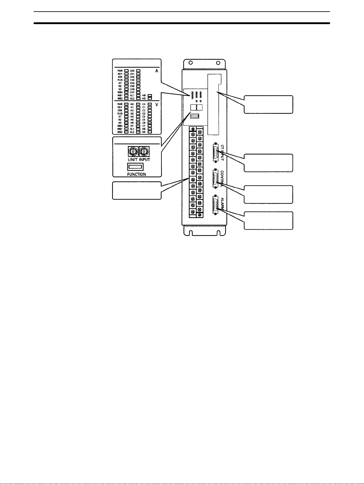
1-1 Component Names and Functions
The component names and their functions are provided here.
Indicators
Communications
connector
Setting selectors and switch
CT INPUT
connector
Indicators
Input terminal block
Indicators
A: E5ZE-8AB (Standard Models with casing)
V: E5ZE-8VB (Heating and Cooling Control Models with casing)
The indicators show the operating status of the E5ZE, as follows:
PWR: Lit when power is ON.
RDY: Lit when the E5ZE is ready to operate.
ERR: Lit when an error occurs in the E5ZE.
RUN: Lit when the E5ZE is operating.
AT: Lit when auto-tuning is being executed.
RD: Lit when the E5ZE is receiving command data.
SD: Lit when the E5ZE is sending response data.
CH0 to CH7:
Lit for the control points for which the corresponding control outputs are ON.
(Not lit for Current Output Models.)
H0 to H7:
Lit for the control points for which the corresponding heating outputs are ON.
(Not lit for Current Output Models.)
C0 to C7:
Lit for the control points for which the corresponding cooling outputs are ON.
AL1: Lit when alarm 1 is ON.
AL2: Lit when alarm 2 is ON.
HB: Lit when the HB (heater burnout) alarm is ON.
HS: Lit when the HS alarm (SSR short circuit) is ON.
MB0 to MB2:
Lit when the memory bank designation inputs (bits 2
external contacts.
CONTROL
connector
ALARM connector
0
to 22) are turned ON with
2
Page 10
Component Names and Functions Section 1-1
Setting Selectors and
Switch
Input Terminal Block
Communications
Connector
The setting selectors and switch are used to select the temperature sensor type,
the unit number, and the functions to be used with the E5ZE. Refer to 2-3 Setting
Selectors and Switch for details on setting methods.
The input terminal block is connected to a DC power supply, temperature sensor, and ground wire. Refer to 2-5 Power Supply and Input Wiring for details on
wiring procedures.
The communications connector is connected to the communications cable. Refer to the E5ZE Multipoint Temperature Controller Communications Manual
(H77) or the E5ZE-8 Multipoint Temperature Controller DeviceNet Communications Manual (H104) for details on communications functions and their applica-
tions.
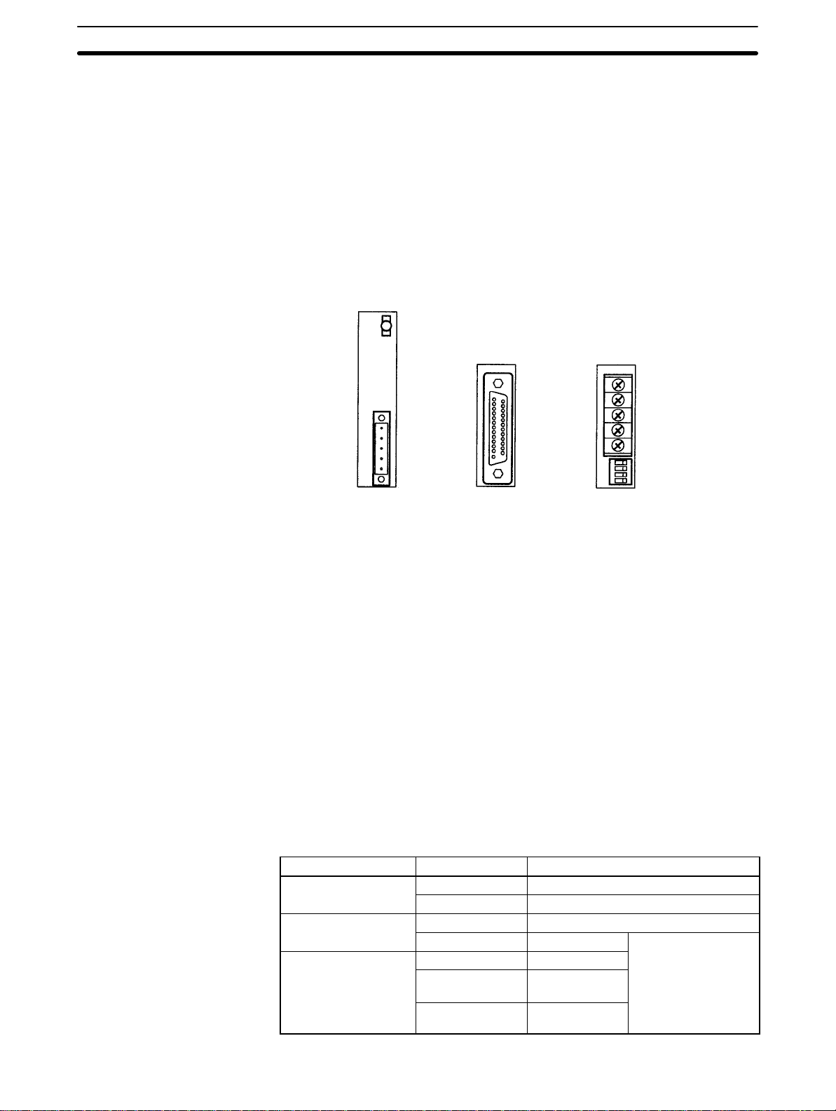
CT INPUT Connector
CONTROL Connector
ALARM Connector
E5ZE-8D1B
(for DeviceNet
communications)
E53-E01
(for RS-232C
Communications
Unit)
E53-E04
(for RS-422/485
Communications
Unit)
The CT INPUT connector is connected to the Current Transformer (CT) to detect
heater burnout or SSR failure. Use E5ZE-CBL Connecting Cables to connect to the Connector Terminal Conversion Unit (XW2B-20G5 for M3.5 terminal
screws or XW2B-20G4 for M2.4 terminal screws). Refer to 2-6 Wiring CT Inputs
and Control/Alarm Outputs for details on wiring procedures.
The CONTROL connector is used to connect the control output and memory
bank designation input contacts. Use E5ZE-CBL Connecting Cables to
connect to the Connector Terminal Conversion Unit (XW2B-20G5 for M3.5 terminal screws or XW2B-20G4 for M2.4 terminal screws). Refer to 2-6 Wiring CT
Inputs and Control/Alarm Outputs for details on wiring procedures.
The ALARM connector for the E5ZE-8A Standard Models is used for
an alarm output and that for the E5ZE-8V Heating and Cooling Control Models is used for cooling control output and alarm output. Use E5ZE-CBL Connecting Cables to connect to the following devices.
Device Model Specifications and Comments
Connector Terminal
Conversion Units
I/O Relay Terminal
I/O Relay Terminal
XW2B-20G4 M2.4 terminal screws
XW2B-20G5 M3.5 terminal screws
G7TC-OC08 8 relay outputs (no cooling outputs)
G7TC-OC16 16 relay outputs
G7VC-OC16 16 relay outputs
G7VC-OA16 16 SSR AC
outputs
G7VC-OD16 16 SSR DC
outputs
Cooling outputs
terminal is not
available on the
standard model.
3
Page 11
System Configuration
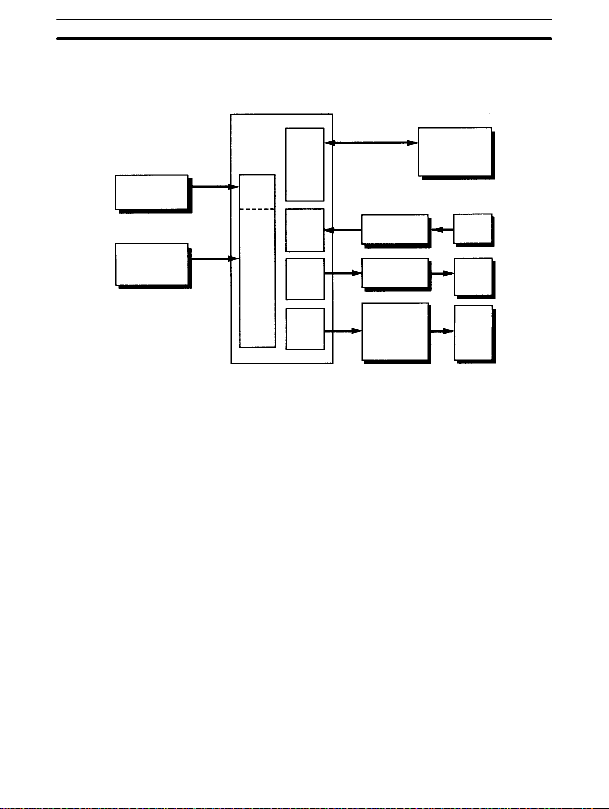
1-2 System Configuration
The following diagram shows the system configuration of the E5ZE.
Section 1-2
24-VDC power
supply
Platinum
resistance
thermometer or
thermocouple
E5ZE
Communications interface:
RS-232C, RS-422 or
RS-485, or DeviceNet
Host device
Computer
Communications
connector
Programmable
Controller
E5ZD-SDL Setting
Display Unit
E5ZE-CBL
Connecting Cables
CT INPUT
connector
XW2B-20G5/4
Connector Terminal
Conversion Unit
Current
Transformer
(CT)
Input
terminal
block
CONTROL
connector
ALARM
connector
XW2B-20G5/4
Connector Terminal
Conversion Unit
XW2B-20G5/4
Connector Terminal
Conversion Unit/
I/O Blocks
Control
outputs
Memory
bank designation inputs
Cooling
control
outputs
Alarm
outputs
Use the specified cables and wiring devices to prevent malfunctions or accidents caused by incorrect wiring.
• The connection between the communications connector and the host device
differs according to the communications interface used. Refer to the E5ZE
Multipoint Temperature Controller Communications Manual (H77) or the
E5ZE-8 Multipoint Temperature Controller DeviceNet Communications Manual (H104) for details.
• There are restrictions on the items that can be set or displayed from the E5ZDSDL Setting Display Unit. Refer to the E5ZD-SDL Setting Display Unit Data-
sheet (H61) for details.
4
Page 12
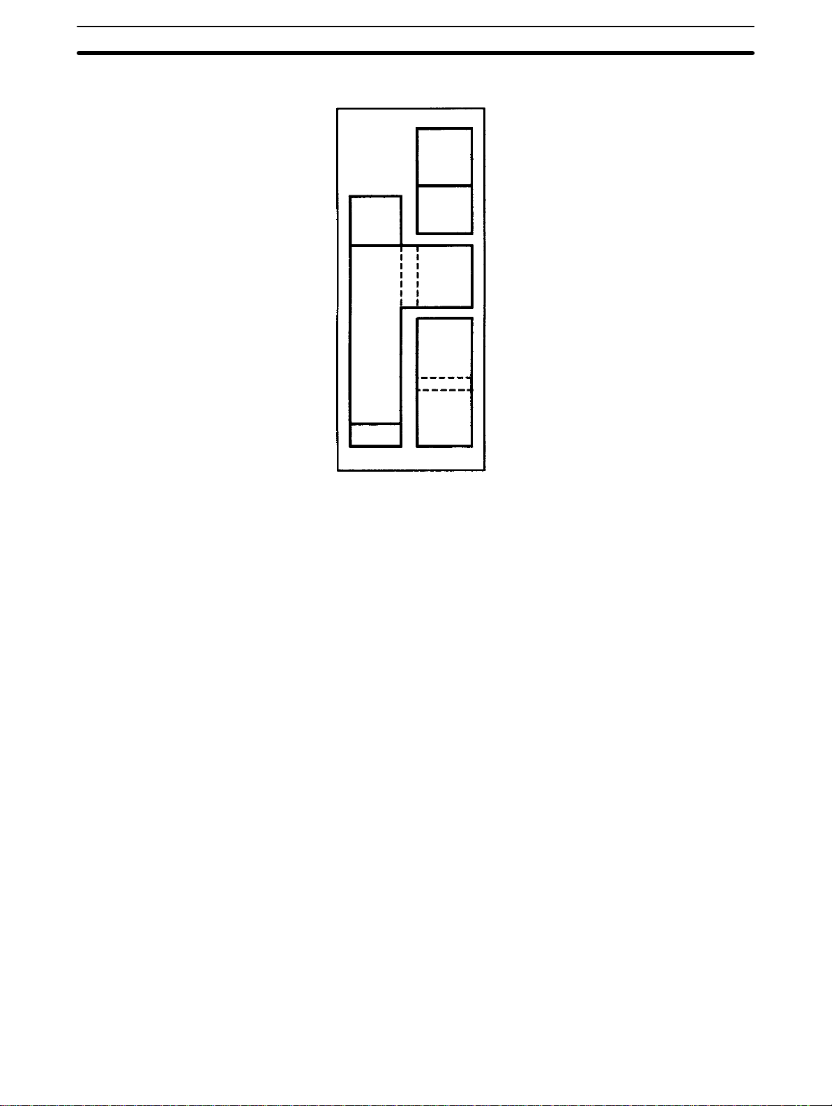
Main Functions
Isolation
Section 1-3
E5ZE
RS-232C
RS-422
RS-485
Power
supply
Input
terminal
block
FG
DeviceNet
CT INPUT
connector
CONTROL
connector
ALARM
connector
The components of the E5ZE contained within bold lines in the above diagram
are electrically isolated.
Note The covers of the CT INPUT, CONTROL, and ALARM connectors are con-
nected to the frame ground (FG).
For the E5ZE-8TC (Thermocouple Input Models), the thermocouple
inputs of the control points are insolated from each other.
1-3 Main Functions
Input Type
CONTROL Outputs
ALARM Outputs
Output Limitations
Ramp
The E5ZE is connected to platinum resistance thermometers or thermocouples,
depending on the model used. The type of temperature sensor is specified using
the INPUT selector on the front panel of the Unit. The input values can be adjusted using the input adjustment function.
The control outputs can be either voltage output or current output, depending on
the model. The control period and direct/reverse operation can be specified using the set values.
A maximum of 2 alarm outputs are possible. There are 12 alarm modes that can
be set for each alarm output according to set values. The outputs are comprehensive output for all control points.
The output values are limited by the following 2 limiters:
• Output limiter
• Output change rate limiter
If an output value is outside the upper or lower limit for the output, the output will
be limited to the preset upper or lower limit. The output change rate limiter limits
the rate at which output values change per unit time.
The ramp function is used to limit the control temperature (set point) from changing rapidly. If the set point changes quicker than the preset rate, the rate of temperature change will be limited to the preset rate, and the temperature will gradually change until it reaches the new temperature. The ramp can be set by the
user.
5
Page 13

Main Functions
Section 1-3
Control Adjustment
Heater Burnout and SSR
Failure Detection
Control Method Selection
Memory Banks
PID and fuzzy constants can be set by executing auto-tuning (AT). If an offset
occurs during P or PD control, manual adjustment is possible using the manual
reset function. Temperature turbulence caused by external disturbances can be
suppressed and controlled using the fuzzy function.
Output short circuits caused by heater burnout or SSR failure can be detected.
Control can be switched between ON/OFF control and the normal 2-PID control
(with 2 degrees of freedom). Manual operation is also possible.
The memory banks store different sets of set values for the control points. There
are 8 memory banks for each control point. Memory banks allow the set values
for a control point to be changed as a group rather than resetting them individually. Use the external contact inputs or communications to designate the required memory bank.
6
Page 14

SECTION 2
Preparations
This section provides details on operations that must be performed before starting the E5ZE, such as installation and wiring.
2-1 List of Models 8. . . . . . . . . . . . . . . . . . . . . . . . . . . . . . . . . . . . . . . . . . . . . . . . . . . . . . . . . . .
2-1-1 Serial Communications Models 8. . . . . . . . . . . . . . . . . . . . . . . . . . . . . . . . . . . . . . .
2-1-2 DeviceNet Communications Models 9. . . . . . . . . . . . . . . . . . . . . . . . . . . . . . . . . . .
2-2 Mounting the Serial Communications Models 10. . . . . . . . . . . . . . . . . . . . . . . . . . . . . . . . . . .
2-3 Setting Selectors and Switch 12. . . . . . . . . . . . . . . . . . . . . . . . . . . . . . . . . . . . . . . . . . . . . . . .
2-3-1 UNIT Selector 12. . . . . . . . . . . . . . . . . . . . . . . . . . . . . . . . . . . . . . . . . . . . . . . . . . . .
2-3-2 INPUT Selector 12. . . . . . . . . . . . . . . . . . . . . . . . . . . . . . . . . . . . . . . . . . . . . . . . . . .
2-3-3 FUNCTION Switch 13. . . . . . . . . . . . . . . . . . . . . . . . . . . . . . . . . . . . . . . . . . . . . . . .
2-4 Installation 15. . . . . . . . . . . . . . . . . . . . . . . . . . . . . . . . . . . . . . . . . . . . . . . . . . . . . . . . . . . . . .
2-4-1 External and Panel Dimensions 15. . . . . . . . . . . . . . . . . . . . . . . . . . . . . . . . . . . . . . .
2-4-2 Mounting 16. . . . . . . . . . . . . . . . . . . . . . . . . . . . . . . . . . . . . . . . . . . . . . . . . . . . . . . .
2-5 Power Supply and Input Wiring 17. . . . . . . . . . . . . . . . . . . . . . . . . . . . . . . . . . . . . . . . . . . . . .
2-5-1 Terminal Block 17. . . . . . . . . . . . . . . . . . . . . . . . . . . . . . . . . . . . . . . . . . . . . . . . . . .
2-5-2 Wiring 17. . . . . . . . . . . . . . . . . . . . . . . . . . . . . . . . . . . . . . . . . . . . . . . . . . . . . . . . . .
2-5-3 Terminal Arrangement 18. . . . . . . . . . . . . . . . . . . . . . . . . . . . . . . . . . . . . . . . . . . . . .
2-5-4 Power Supply 18. . . . . . . . . . . . . . . . . . . . . . . . . . . . . . . . . . . . . . . . . . . . . . . . . . . . .
2-5-5 Ground 18. . . . . . . . . . . . . . . . . . . . . . . . . . . . . . . . . . . . . . . . . . . . . . . . . . . . . . . . . .
2-5-6 Thermocouple Input 19. . . . . . . . . . . . . . . . . . . . . . . . . . . . . . . . . . . . . . . . . . . . . . . .
2-5-7 Platinum Resistance Thermometer Input 19. . . . . . . . . . . . . . . . . . . . . . . . . . . . . . . .
2-6 Wiring CT Inputs and Control/Alarm Outputs 19. . . . . . . . . . . . . . . . . . . . . . . . . . . . . . . . . . .
2-6-1 CT Inputs 20. . . . . . . . . . . . . . . . . . . . . . . . . . . . . . . . . . . . . . . . . . . . . . . . . . . . . . . .
2-6-2 Outputs 21. . . . . . . . . . . . . . . . . . . . . . . . . . . . . . . . . . . . . . . . . . . . . . . . . . . . . . . . . .
2-7 Connecting Communications 24. . . . . . . . . . . . . . . . . . . . . . . . . . . . . . . . . . . . . . . . . . . . . . . .
2-7-1 RS-232C 24. . . . . . . . . . . . . . . . . . . . . . . . . . . . . . . . . . . . . . . . . . . . . . . . . . . . . . . . .
2-7-2 RS-422 and RS-485 25. . . . . . . . . . . . . . . . . . . . . . . . . . . . . . . . . . . . . . . . . . . . . . . .
2-7-3 DeviceNet Interface 27. . . . . . . . . . . . . . . . . . . . . . . . . . . . . . . . . . . . . . . . . . . . . . . .
7
Page 15

2-1 List of Models
2-1-1 Serial Communications Models
2-1SectionList of Models
No. of
control
Casing Control
method
points SSR failure
Control
output
Heater
burnout and
detection
Commu-
nications
Input type
Thermocouple Platinum
resistance
thermometer
8 Yes Standard Option Option Option E5ZE-8AAAMTCB-E E5ZE-8AAAMPB-E
Heating
Option Option Option E5ZE-8VAAMTCB-E E5ZE-8VAAMPB-E
and
cooling
Model Number Legend:
E5ZE-8AAM-E
1234567
1. Control Point
8: 8
2. Control Method
A: Standard
V: Heating and cooling
3. Control Output
A: Option (see note 1)
4. Heater Burnout and SSR Failure Detection (see note 2)
A: Option (see note 3)
5. Communications
M: Option (see note 4)
6. Input Type
TC: Thermocouple
P: Platinum resistance thermometer
7. Casing
B: Yes
Note: 1. The E53-E8Q Voltage Output Unit or the E53-E8C
Current Output Unit can be used with the E5ZE. The
E53-E8Q Voltage Output Unit and the E53-E8C
Current Output Unit are sold separately.
2. The heater burnout and SSR failure detection
function of the E5ZE will be invalid if the heating side
control output of the E5ZE is current output.
3. The E54-E8CT CT Input Unit is required for the
heater burnout and SSR failure detection. The
E54-E8CT CT Input Unit is sold separately.
4. The E53-E01 Communications Unit for RS-232C
communication or the E53-E04 Communications Unit
for RS-422 and RS-485 communication can be used
with the E5ZE. The E53-E01 Communications Unit
and the E53-E04 Communications Unit are sold
separately.
I/O Units (Order Separately)
Units Models
RS-232C Communications Unit E53-E01
RS-422/485 Communications Unit E53-E04
CT Input Unit E54-E8CT
Voltage Output Unit E53-E8Q
Current Output Unit E53-E8C
8
Page 16

2-1-2 DeviceNet Communications Models
2-1SectionList of Models
No of control
points
Casing Control
method
Control
output
HBA and SSR
failure
Iput type Name
detection
8 Yes Standard Voltage Yes Thermocouple E5ZE-8AQH
D1TCB
24VDC
8 Yes Standard Voltage Yes Platinum
resistance
E5ZE-8AQH
D1PB 24VDC
thermometer
8 Yes Standard Current No Thermocouple E5ZE-8ACA
D1TCB
24VDC
8 Yes Standard Current No Platinum
resistance
E5ZE-8ACA
D1PB 24VDC
thermometer
8 Yes Heating and
Cooling
Voltage Yes Thermocouple E5ZE-8VQH
D1TCB
24VDC
8 Yes Heating and
Cooling
Voltage Yes Platinum
resistance
E5ZE-8VQH
D1PB 24VDC
thermometer
8 Yes Heating and
Cooling
Current No Thermocouple E5ZE-8VCA
D1TCB
24VDC
8 Yes Heating and
Cooling
Current No Platinum
resistance
E5ZE-8VCA
D1PB 24VDC
thermometer
Model Number Legend:
E5ZE-8
1234567
1. Control Point
8: 8
2. Control Method
A: Standard control
V: Heating and cooling control
3. Control Output
Q: Voltage output
C: Current output
4. Heater Burnout and SSR Failure Detection Function
(Not available with Current Output Models.)
A: No
H: Yes
5. Communications Function
D1: DeviceNet
6. Input Type
TC: Thermocouple
P: Platinum resistance thermometer
7. Casing
B: Yes
9
Page 17
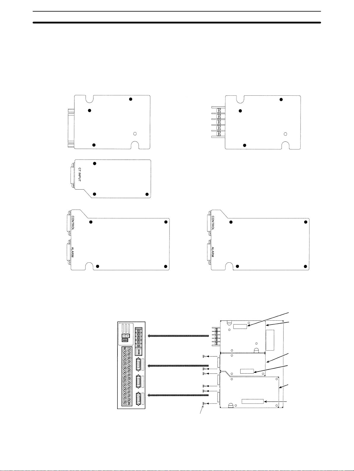
2-2 Mounting the Serial Communications Models
2-2SectionMounting the Serial Communications Models
I/O Units
Communication Unit
CT Input Unit
Output Unit
E53-E01 for
RS-232C
E54-E8CT
I/O Units are not mounted on the E5ZE.
Mount the appropriate I/O Units according to the specification of the E5ZE.
The diagram below is the view from the back of component side.
Type of I/O Units
E53-E04 for
or
Use this CT input unit in combination
with the E53-E8Q voltage output unit.
RS-422/RS-485
E53-E8Q for voltage
output
or
E53-E8C for current
output
Tighten the screws through the holes marked with a black dot () to the fixing
studs of the E5ZE.
Mounting Position of I/O Units
Communication Unit
CT Input Unit
Output Unit
Remove this screw when the Unit is
mounted on the model with casing.
Connector
Communication
Unit
CT Input Unit
Connector
Output Unit
Connector
10
Page 18
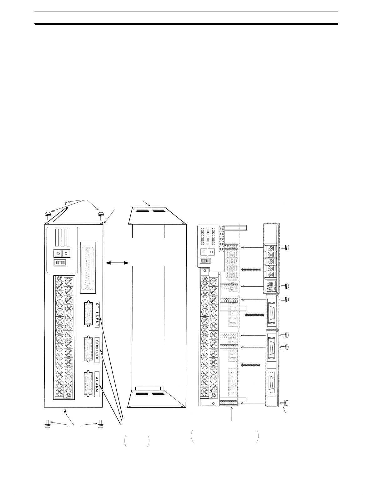
2-2SectionMounting the Serial Communications Models
Mounting the Units
Casing securing
Use appropriate Phillips screwdriver for the screws. Use of an inappropriate
screwdriver may damage the screws and cause insufficient tightening.
Mount the Units in an environment where anti-static electricity countermeasures
have been taken.
Store the removed screws carefully and use them again when required.
Model With Casing
1, 2, 3... 1. Remove the connector fixing screws (2 screws each for a connector) from
the Units (except for communication unit).
2. Remove the casing fixing screws (6 screws).
3. Remove the casing.
4. Mount the Units in the same manner as the model without casing.
5. Fix the connector to the case using the connector fixing screws with a torque
of 0.34 to 0.39 Nm.
6. Replace the casing in its original position using six casing fixing screws.
Casing
Case
Casing securing
Remove the casing after removing
the casing fixing screws(6 pcs.)
Identification label for
connector
CT INPUT
CONTROL
ALARM
Fixing studs for the Units
Communication Unit : 3 pcs.
CT Input Unit : 3 pcs.
Output Unit : 4 pcs.
Communication Unit
(sold separately)
E53-E01 or E53-E04
(The diagram shows
E53-E04)
CT Input Unit
(sold separately )
E54-E8CT
Output Unit
(sold separately)
E53-E8Q or E53-E8C
The Unit fixing screws are
mounted on the fixing studs at
the factory.
11
Page 19
2-3 Setting Selectors and Switch
Observe the following precautions when operating the selectors and switch.
• Always make sure the power is OFF before changing the selectors and switch.
• Use a small flat-blade screwdriver to change the selector and switch settings,
and be sure that the selectors are correctly positioned.
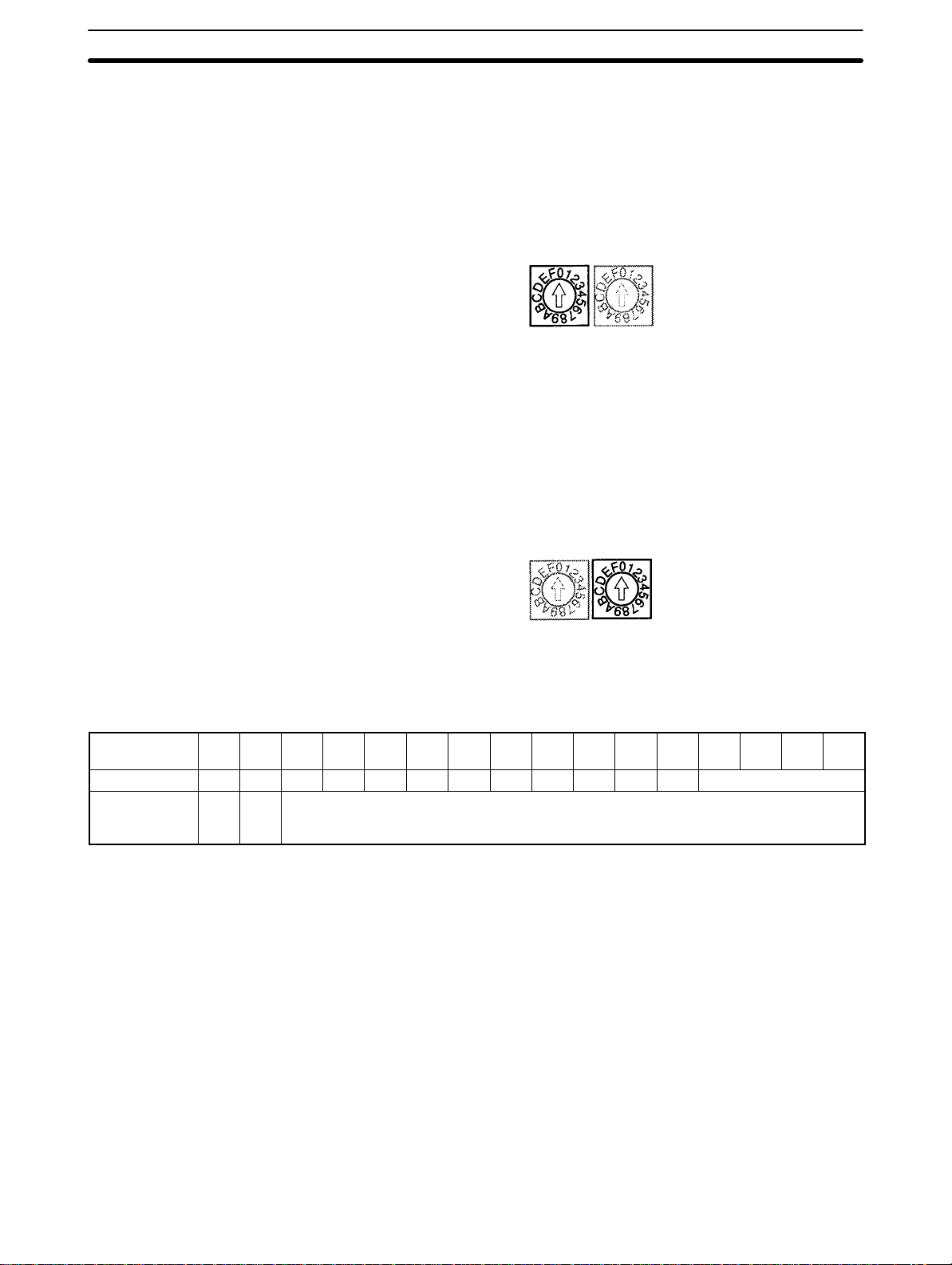
2-3-1 UNIT Selector
When serial communications are being used, the UNIT selector must be set so
that the host device can recognize the E5ZE unit number.
When more than one E5ZE Multipoint Temperature Controller is being used with
RS-422 or RS-485 communications, set a different unit number for each E5ZE.
• The selector settings 0 to F correspond to unit numbers 00 to 0F. The factory
setting of 0 corresponds to unit number 00.
2-3SectionSetting Selectors and Switch
UNIT INPUT
2-3-2 INPUT Selector
UNIT INPUT
Set the INPUT selector according to the type of temperature sensor connected
to the E5ZE. The selector positions and corresponding temperature sensors are
as follows:
Selector
setting
Thermocouple K J R S T E B N L U W PLII Not used.
Platinum
resistance
thermometer
0 1 2 3 4 5 6 7 8 9 A B C D E F
Pt JPt Not used.
• The factory setting is 0.
• The platinum resistance thermometer settings “Pt” and “JPt” indicate Pt100
and JPt100 respectively.
12
Page 20
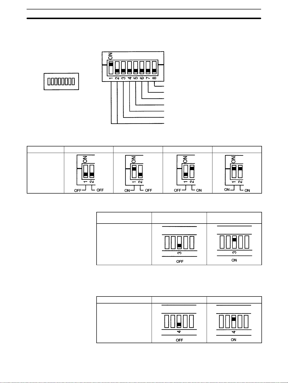
2-3-3 FUNCTION Switch
The FUNCTION switch is used to set the parameters of the E5ZE, such as the
baud rate and startup operation.
FUNCTION
2-3SectionSetting Selectors and Switch
Operation mode change
Not used. (Always set to OFF.)
Temperature unit (°C or °F)
Startup operation
E5ZD-SDL Setting Display Unit connection
Memory bank designation method
Baud rate (serial communications)
Baud Rate (Serial
Communications)
Baud rate 19,200 bps 9,600 bps 4,800 bps 2,400 bps
Pin 1
Pin 2
Set the baud rate using pins 1 and 2 to the baud rate of the host device connected to the EZ5E.
The factory setting is 9,600 bps (pin 1 ON, pin 2 OFF).
Memory Bank Designation
Method
Pin 3 is used to set the memory bank designation method.
Memory bank
designation
Pin 3
Communications Contact inputs
The factory setting is for communications (pin 3 OFF).
When contact inputs are used to switch memory banks, the specified memory
bank will be used for all control points.
E5ZD-SDL Setting Display
Unit Connection
Pin 4 is used to specify when an E5ZD-SDL Setting Display Unit is connected.
E5ZD-SDL connection Not connected Connected
Pin 4
The factory setting is for no connection (pin 4 OFF). Set pin 4 to ON when an
E5ZD-SDL Setting Display Unit is to be connected to the E5ZE.
13
Page 21
2-3SectionSetting Selectors and Switch
Startup Operation
Temperature Unit
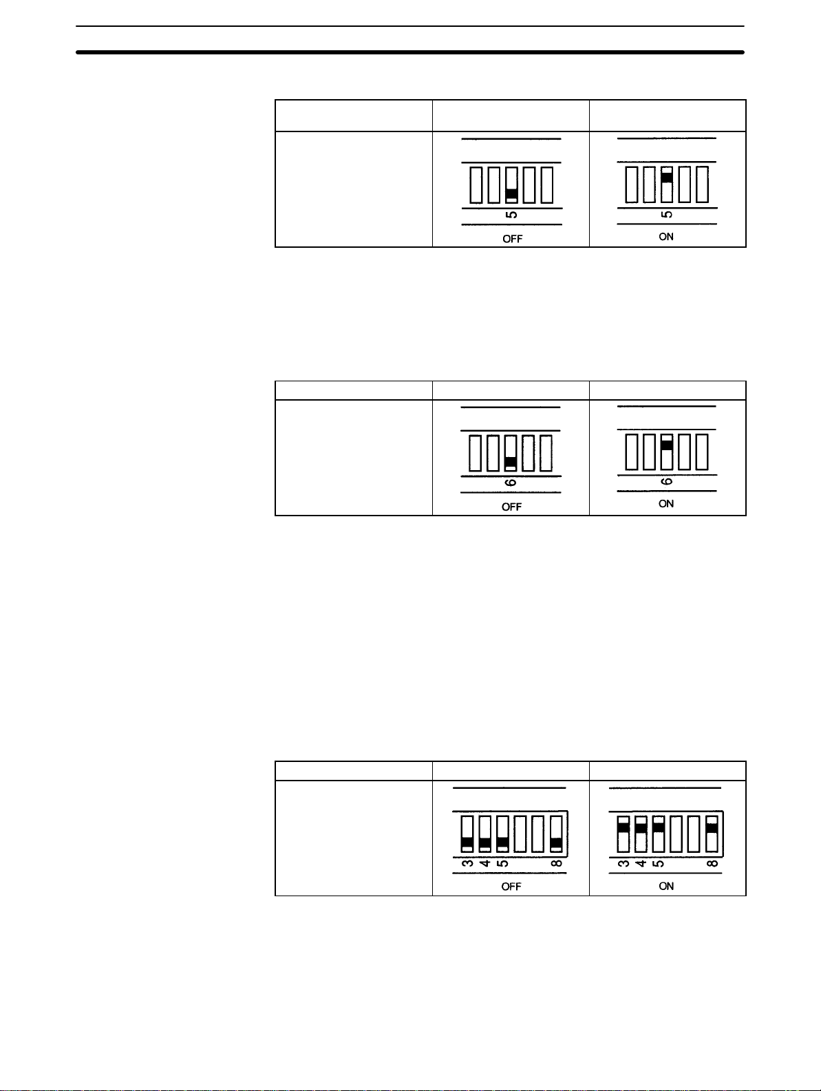
Pin 5 is used to set the startup operation.
Startup operation Stop operation control Continue status at
power OFF
Pin 5
The factory setting is for stop operation control (pin 5 OFF).
If the power is turned OFF during manual operation and pin 5 is set to ON (con-
tinuous operation), manual operation will automatically begin when the power is
turned ON again. The output value will be 0%.
Pin 6 is used to set the unit for measuring temperature.
Temperature unit
Pin 6
C F
1, 2, 3... 1. Initialize the setting data.
Operation Mode Change
The factory setting is for degrees Celsius (pin 6 OFF).
When the temperature unit is changed, the temperature data does not automati-
cally change, so make sure to reset the temperature using the following procedure.
2. Recalculate the data according to the following conversion formula and reset the control data within the setting range.
(value in F) = 1.8 x (value in C) + 32
3. Store the settings in memory.
Pins 3, 4, 5, and 8 are used to change the operation mode.
E5ZE operation mode Control mode Hardware test mode
Pins 3, 4, 5, and 8
The factory setting is for Control Mode (pins 3, 4, 5, and 8 all OFF).
14
Control Mode: Use for normal temperature control.
Hardware Test Mode: Use for testing Peripheral Devices and wiring.
Refer to Appendix E for details on how to use Hardware Test Mode. Outputs can
be turned ON and OFF in Hardware Test Mode regardless of the process value.
Page 22
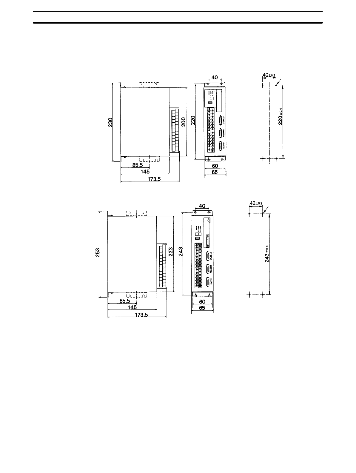
2-4 Installation
2-4-1 External and Panel Dimensions
2-4SectionInstallation
Serial Communications Model
E5ZE-8D1B
(DeviceNet Interface)
Unit: mm Mounting Hole Dimensions
Four, M4
Four, M4
15
Page 23

2-4-2 Mounting
Precautions
2-4SectionInstallation
Mount the Unit using the methods shown here. The Unit will not operate properly
if other methods are used to mount the Unit.
• Use the following mounting screws. Make sure the length of the screws is appropriate for the mounting panel used.
E5ZE-8B: 4 x M4 screws
• Use spring and flat washers and tighten to a torque of 0.43 to 0.58 N m {4.4 to
5.9 kgf cm}.
• Do not mount the terminal block with the connectors facing upwards. Doing so
may cause measurement errors.
Mounting Bracket
Mounting Models
Secure the mounting
bracket
Secure the mounting bracket using the screws provided according to the appropriate mounting method. Tighten to a torque of 0.43 to 0.58 N m {4.4 to
5.9 kgf cm}.
Mounting screws
(4 x M4 + spring
and flat washers)
Panel
Secure the mounting
bracket
Mounting screws
(4 x M4 + spring
and flat washers)
Panel
16
Page 24
2-5 Power Supply and Input Wiring
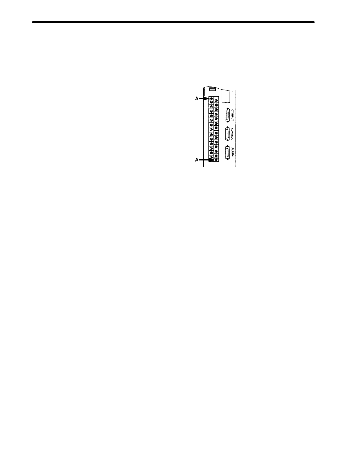
2-5-1 Terminal Block
The input terminal block has been designed with a removable terminal-screw
panel. When connecting the power supply or temperature sensor, the terminalscrew panel can be conveniently removed before wiring.
• To remove the terminal-screw panel, loosen the two screws alternately indicated by A in the above diagram.
• To mount the terminal-screw panel, insert it into the terminal block and secure
the two screws (A) alternately.
• If the terminal block has been removed from the E5ZE Thermocouple Input
Model, when reconnecting make sure that the E5ZE’s lot number and serial
number are the same as those of the terminal block. Accuracy cannot be guaranteed for a Unit that has been connected to a terminal block with a different lot
number and serial number.
2-5SectionPower Supply and Input Wiring
2-5-2 Wiring
• Always turn OFF the power supply before performing any wiring.
• Be sure to check polarity when connecting the power supply and temperature
sensor.
• Wire the power supply cables separately from the temperature sensor cables
to prevent noise interference.
• Use either crimp terminals or solder the wire ends when wiring terminals.
• Tighten the terminal screws.
• Wire the power lines close to the terminal block to prevent external force being
exerted on the power lines from torsion or weight.
• Do not use the terminals that are marked “Don’t use.”
• Do not bend the crimp terminals after they have been connected and the
screws have been tightened.
17
Page 25
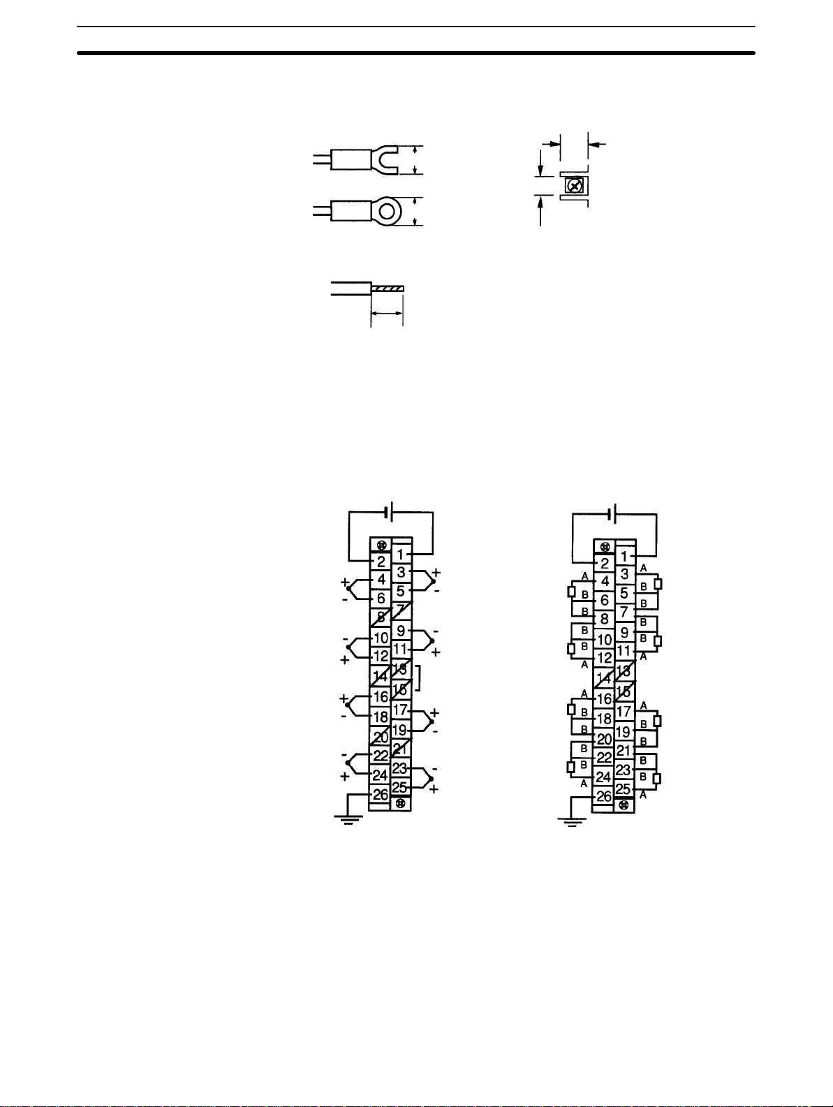
• Use the crimp terminals shown in the following diagram.
2-5SectionPower Supply and Input Wiring
Crimp Terminals
End Soldering
Applicable wire size: AWG 22 to 16
2-5-3 Terminal Arrangement
The following diagram shows the arrangement of terminals on the terminal
block.
Terminal Block Screw Dimensions
9.5 mm
7.9 mm max.
8.1 mm
7.9 mm max.
Length of exposed wire: 6 to 8 mm
Thermocouple Platinum Resistance Thermometer
24 VDC 24 VDC
8 x M3.5 self-rising screws
2-5-4 Power Supply
ch 0
Don’t use
ch 1
Don’t use
ch 2
Don’t use
ch 3
FG
ch 4
Don’t use
ch 5
Don’t use
ch 6
Don’t use
ch 7
ch 0
ch 1
Don’t use
ch 2
ch 3
FG
ch 4
ch 5
Don’t use
ch 6
ch 7
The power supply specifications are as follows:
24 VDC (20.4 to 26.4 VDC) 15 W + 20% max.
Use a power supply with a minimum capacity of 2 A. Be sure to consider the inrush current.
2-5-5 Ground
18
Connect the ground wire to terminal 26. Ground to 100 Ω max.
Page 26

2-5-6 Thermocouple Input
• The terminal polarity varies with the control point. Be sure to check polarity
when connecting thermocouples to the terminal block.
• When extending the input lead wires, connect compensating conductors that
match the thermocouple used. Do not solder the ends of the thermocouple or
compensating conductors.
• Never remove the cold junction compensator connected to terminals 13 and
15.
• Do not touch the cold junction compensators.
• Short-circuit the positive and negative terminals of each control point that is not
used. The process value for each control point that is not being used will be the
ambient temperature of the terminal block.
2-5-7 Platinum Resistance Thermometer Input
• The terminal polarity varies with the control point. Be sure to check polarity
when connecting platinum resistance thermometers to the terminal block.
• When extending the input lead wires, make sure that the conductor resistance
is the same for the A terminal and two B terminals.
• Connect a 100- to 200-Ω resistor between the A and B terminals of any unused
control point, and short-circuit the two B terminals of any unused control point.
The process value for each control point that is not being used will correspond
to the resistance of the resistor connected to the terminals.
2-6SectionWiring CT Inputs and Control/Alarm Outputs
2-6 Wiring CT Inputs and Control/Alarm Outputs
CT inputs and control/alarm outputs are connected using wiring-reduction devices. Always use E5ZE-CBL Connecting Cables to connect the E5ZE to
the wiring-reduction devices. Refer to the wiring-reduction device datasheet for
details, including wiring precautions.
Use the identification labels provided for each cable to prevent incorrect wiring of
the CONTROL, ALARM, and CT INPUT connectors.
Cable identification label
Hood: Connect to
FG terminal: Connect to
improve noise resistance
E5ZE-CBL Connecting Cable
the FG terminal.
19
Page 27

2-6-1 CT Inputs
Cable Connections
2-6SectionWiring CT Inputs and Control/Alarm Outputs
The CT INPUT connector can be connected to an XW2B-20G5 Connector Terminal Conversion Unit (20-terminal M3.5 terminal block) or an XW2B-20G4
Connector Terminal Conversion Unit (20-terminal M2.4 terminal block).
E5ZE-CBL Connecting Cable
XW2B-20G5/4 Connector Terminal
Conversion Unit
Wiring
CT0 to CT7
The following diagram shows the terminal arrangement for CT inputs when a
XW2B-20G5/4 Connector Terminal Conversion Unit is connected. Connect CT0
to CT7 to the CT inputs for control points 0 to 7. For example, CT0 will detect
heater burnout or SSR failure for the output of control point 0.
Use the E54-CT1 or E54-CT3 Current Transformer (CT). Refer to Appendix B
for further details on the CT. Refer to 3-10 Heater Burnout Detection for details
on wiring the CT.
20
Page 28

2-6-2 Outputs
Cable Connections
E5ZE-CBL
Connecting Cable
2-6SectionWiring CT Inputs and Control/Alarm Outputs
XW2B-20G5/4 Connector Terminal
Conversion Unit
Heating control output, memory bank designation input
XW2B-20G5/4 Connector Terminal
Conversion Unit
G7TC-OC08/16, G7VC-O16
I/O Blocks
CONTROL Connector
Wiring
Cooling control output, ALM1 and ALM2, HB alarm,
HS alarm, temperature controller error
The CONTROL connector can be connected to an XW2B-20G5 Connector T erminal Conversion Unit (20-terminal M3.5 terminal block) or an XW2B-20G4
Connector Terminal Conversion Unit (20-terminal M2.4 terminal block).
• The terminal arrangement for outputs when an XW2B-20G5/4 Connector Terminal Conversion Unit is connected is shown in the following diagram.
CONTROL Connector Terminal Block
2
1
2
2
2
0
• The output specifications are shown in the following table. Connect a load that
is compatible with the output type and output rating.
Output Specification
Voltage output Output voltage: 12 ± 1.2 VDC
Output current: 30 mA max.
Current output
Output current: 4+0/
–0.6
to 20
Load resistance: 600 Ω max.
+2
/–0 mA DC
21
Page 29

• When connecting a relay load, insert a diode to prevent surge.
2-6SectionWiring CT Inputs and Control/Alarm Outputs
E5ZE
ch n: Control point 0 to 7
ch n +
Relay
ch n –
• The following diagram shows the wiring when designating the memory bank
using contact inputs.
No Contact InputContact Input
E5ZE
Terminal
numbers 2,
3, and 4
Terminal
number 1
ON: Short-circuit resistance: 1 kΩ max.
Outflow current: 3 mA DC
OFF: Open resistance: 100 kΩ min.
E5ZE
Terminal
numbers 2,
3, and 4
Terminal
number 1
ON: Residual voltage: 2 VDC max.
Outflow current: 3 mA DC
OFF: Leakage current: 1 mA max.
ALARM Connector Wiring
The ALARM connector can be used with the following devices.
• XW2B-20G5 or XW2B-20G4 Connector Terminal Conversion Unit
• G7TC-OC16, G7TC-OC08, or G7VC-O16 I/O Block
The following diagram shows the terminal arrangement when the ALARM connector is connected to an XW2B-20G5 or XW2B-20G4 Connector Terminal
Conversion Unit. In the diagram, RL indicates a relay load.
Cooling control output (Do not use these terminals with E5ZE-8A Standard Models.)
Don’t use
Common
Don’t use Don’t use Don’t use Don’t use
ch 7 ch 6 ch 5 ch 4 ch 3 ch 2 ch 1 ch 0
Common
Temperature controller error
HS alarm HB alarm Alarm 2 Alarm 1
• The following table shows the specifications for alarm output and cooling control output. The E5ZE does not have an overcurrent protection function for
alarm output and cooling control output. Connect a load to each alarm output
and cooling control output that corresponds to the output ratings.
Output Specifications
Open collector output NPN, 30 VDC, 50 mA max.
Residual voltage when ON: 2 VDC max.
Leakage current when OFF: 1 mA max.
22
• Do not use the terminals marked “Don’t use.”
Page 30

• When connecting a relay load, insert a diode to prevent surge.
2-6SectionWiring CT Inputs and Control/Alarm Outputs
Connecting G7TC I/O
Blocks
G7TC-OC08
G7TC-OC16
E5ZE
ALM: Temperature Controller error, Alarm 1 and 2, HB, and HS
Relay
The following diagrams shows an ALARM connector connected to a G7TCOC08 and G7TC-OC16 I/O Block respectively.
Don’t use Don’t use
Internal circuit of G7TC I/O Block
24 VDC/
12 VDC
Alarm 1
Alarm 2
Don’t use Don’t use
HS
Temperature Controller error
alarm
HB alarm
G7T (SPST-NO)
Connecting G7VC I/O
Blocks
G7VC-O16
24 VDC/
12 VDC
Alarm 1
Alarm 2
HS
alarm
HB alarm
Temperature
Controller
error
0
Cooling control output (Do not use with
E5ZE-8A Standard Models.)
3
1
2
6
4
5
7
Points
• Do not use terminals marked “Don’t use.” Doing so may cause the E5ZE or
G7TC to malfunction.
• G7TC-OC08 I/O Blocks cannot be used with E5ZE-8V Heating and
Cooling Control Models.
• Refer to the separate datasheets for details on precautions for the I/O Blocks.
The following diagram shows an ALARM connector connected to a G7VCO16 I/O Block.
Cooling control output (Do not use with
E5ZE-8A Standard Models)
24 VDC
Alarm 2
Alarm 1
A2 to A6 common
HB alarm
Temperature
HS
controller error
alarm
A12 to A19 common
• Do not use terminals marked “Don’t use.” Doing so may cause the E5ZE or
G7VC to malfunction.
23
Page 31

• The following G7VC-O16 I/O Blocks for output are available.
G7VC-OC16: Relay outputs
G7VC-OA16: SSR AC outputs
G7VC-OD16: SSR DC outputs
• Refer to the separate datasheets for details on precautions for the I/O Blocks.
2-7 Connecting Communications
The wiring and connections of the communications interfaces are described
here. For further details, refer to the following manuals.
Serial communications: E5ZE Multipoint Temperature Controller Communica-
tions Manual (H77)
DeviceNet communications: E5ZE-8 Multipoint Temperature Controller Devi-
ceNet Communications Manual (H104)
2-7-1 RS-232C
• Mount the RS-232C Communications Unit on the E5ZE Serial Communications Model.
• The E5ZE is connected to the RS-232C interface in the ratio of 1:1.
• Refer to the E5ZE Multipoint Temperature Controller Communications Manual
(H77) for details on communications.
2-7SectionConnecting Communications
Cable Connections
• The maximum cable length is15 m. To extend the transmission path, use the
OMRON Z3RN RS-232C Optical Interface.
• Use shielded twisted-pair cable with a wire thickness of AWG28 minimum.
• Use the following OMRON 25-pin D-sub Connectors or equivalent.
Plug: XM2A-2501 Connector
Hood: XM2S-2511 Hood
Host device
RS-232C
Symbol
Pin
Shield
Pin
Symbol
E5ZE
Line driver/receiver
LT1181CS or
equivalent
• The E5ZE’s RS-232C communications do not support a CD (carrier detect)
signal from the host device. If the CD signal is required, provide support at the
host device.
When using the RS-232C auxiliary setting jack on the E5ZE-8D1B
(DeviceNet Model with casing), use the following Connecting Cables.
• ES100-CT021-202 (25-pin)
This Cable is used to connect the E5ZD-SDL1 Setting Display Unit.
• ES100-CT023-202 (9-pin)
The RS-232C auxiliary setting jack is designed to be used only temporarily for
initial settings and performing maintenance. Do not use the RS-232C auxiliary
setting jack to mount the E5ZE to a device. If the RS-232C auxiliary setting jack
is left connected for a long time, the reliability of the connection will deteriorate.
24
Page 32

2-7-2 RS-422 and RS-485
• Mount the RS-422/485 Communications Unit on the E5ZE Serial Communications Model.
• The E5ZE can be connected to the communications interface in the ratio of 1:N
with a maximum of 16 Units connected.
• The maximum cable length is 500 m.
• Refer to t h e E5ZE Multipoint Temperature Controller Communications Manual
(H77) for further details on communications.
Parameter Settings
• Specify the following parameters using the communications DIP switch. Always turn OFF the power before changing the switch.
• Communications interface
• Terminating resistance
2-7SectionConnecting Communications
Setting Pin RS-422 RS-485
Terminating
resistance
(pins 3 and 4)
Interface (pins 1 and 2) Pin 2
• Set the terminating resistance at both ends of the transmission path including
the host device. If terminating resistance is to be set at devices other than the
E5ZE, make sure that the total terminating resistance value of the transmission paths is at least 100 Ω.
Wiring the Communications Terminal Block
• Always turn OFF the power supply before wiring.
• Wire the power lines and communications cables separately to prevent noise
interference.
• Use crimp terminals or solder the wire ends when wiring the terminals.
E5ZE-804
Yes Pin 4
Pin 3
No Pin 4
Pin 3
Pin 1
• Tighten the terminal screws to a torque of 0.59 N m, or 6 kgf cm.
• Do not apply a force of more than 100 N or 10.2 kgf to the terminal screws.
• Do not bend any crimp terminals after connecting them to the terminal screws
and tightening.
25
Page 33

• The following crimp terminals can be used.
Crimp Terminal Terminal Block Screw Dimensions
2-7SectionConnecting Communications
RS-422 Wiring
End Soldering
Host device
Signal
6 mm max.
6.25 mm
6 mm max.
Length of exposed wire: 6 to 7 mm
Applicable wire size: AWG14 to 20
Shielded twisted-pair cable
E5ZE
Termi-
Signal
nal
Shield
10.4 mm
M3 x 7.2 screws with
square washers
+5 V
SN751177N or
equivalent
51 k
4.7 k
4.7 k
51 k
6.8 V
E5ZE
Terminal
Communications DIP switch
Signal
Terminating resistance
26
Page 34

RS-485 Wiring
• Do not use terminals 1 and 2.
Host device
Signal
Shield
E5ZE
Terminal
Signal
E5ZE
Terminal
Signa
2-7SectionConnecting Communications
+5 V
SN751177N or
equivalent
51 k
4.7 k
4.7 k
51 k
6.8 V
l
Communications DIP switch
2-7-3 DeviceNet Interface
• Use the E5ZE-8D1B for DeviceNet communications.
• Refer to the DeviceNet Operation Manual (W267) for details on DeviceNet
Network configurations and connection methods.
• Refer to the E5ZE-8 DeviceNet Communications Manual (H104) for details on
DeviceNet communications applications.
Communications Settings
RS-232C auxiliary
setting jack
DeviceNet DIP
switch
DeviceNet
connector
Set the following parameters using the DeviceNet DIP switch.
• Node addresses
• Baud rate
• E5ZE operation for DeviceNet communications errors.
Node address
Terminating resistance
Communications error operations
Always set to OFF
Baud rate
• Pins 1 to 6 are used to set the node address. The factory setting is 00 (pins 1 to
6 all OFF).
Pin 1 Pin 2 Pin 3 Pin 4 Pin 5 Pin 6
0
2
1
2
2
2
3
2
4
2
5
2
27
Page 35

2-7SectionConnecting Communications
• Pins 7 and 8 are used to set the baud rate. Be sure to set the baud rate to match
that of the DeviceNet Master Unit. The factory setting is 125 kbps (pins 7 and 8
OFF).
Baud rate Pin 7 Pin 8
125 kbps OFF OFF
250 kbps ON OFF
500 kbps OFF ON
Not used ON ON
• Pin 10 is used to set the E5ZE operation when a DeviceNet communications
error occurs.
ON: The E5ZE continues to operate according to the data that was
transmitted immediately before the error occurred.
OFF: The E5ZE stops operating.
The factory setting is ON.
• A DeviceNet transmission error is a connection time-out error or a transmission data error that has occurred during communications between the DeviceNet Master and the E5ZE.
Cable Connections
Number of Connectable
Units
• The following diagram shows how the DeviceNet connector is wired.
• Multi-drop connections cannot be used.
Black (V–)
Blue (CAN L)
Shield
White (CAN H)
Red (V+)
The number of E5ZE-8D1B DeviceNet Models with casing that can be
connected to one DeviceNet Master Unit depends on the capability of the Master
being used. The maximum number of Units that can be connected to one Master
is calculated according to the number of words allocated to the
E5ZE-8D1B and the number of words that can be used by the Master.
• The number of words allocated to the E5ZE-8D1B is as follows:
Inputs: 14 words
28
Outputs: 9 words
Message communications (FINS messages) are used.
Example: C200HW-DRM21-V1 DeviceNet Master Unit without Configurator
• The number of words used by the Master is 50 input words and 50 output
words (current as of July 31, 1998). The E5ZE-8D1B is allocated
14 words, so the maximum number of Units that can be connected is as follows:
50 14 = 3 Units.
Page 36

SECTION 3
Functions
This section provides details on the functions of the E5ZE and their applications. For details on the settings and measurement
values for the functions, refer to the E5ZE Multipoint Temperature Controller Communications Manual (H77) and the
E5ZE-8 Multipoint Temperature Controller DeviceNet Communications Manual (H104).
3-1 Data Configuration 30. . . . . . . . . . . . . . . . . . . . . . . . . . . . . . . . . . . . . . . . . . . . . . . . . . . . . . . .
3-2 I/O Settings 31. . . . . . . . . . . . . . . . . . . . . . . . . . . . . . . . . . . . . . . . . . . . . . . . . . . . . . . . . . . . . .
3-2-1 Input Type 31. . . . . . . . . . . . . . . . . . . . . . . . . . . . . . . . . . . . . . . . . . . . . . . . . . . . . . .
3-2-2 Input Shift 31. . . . . . . . . . . . . . . . . . . . . . . . . . . . . . . . . . . . . . . . . . . . . . . . . . . . . . .
3-2-3 Control Period 31. . . . . . . . . . . . . . . . . . . . . . . . . . . . . . . . . . . . . . . . . . . . . . . . . . . .
3-2-4 Direct/Reverse Operation 32. . . . . . . . . . . . . . . . . . . . . . . . . . . . . . . . . . . . . . . . . . .
3-3 Set Point and Process Value 32. . . . . . . . . . . . . . . . . . . . . . . . . . . . . . . . . . . . . . . . . . . . . . . . .
3-3-1 Setting Set Point 32. . . . . . . . . . . . . . . . . . . . . . . . . . . . . . . . . . . . . . . . . . . . . . . . . .
3-3-2 Reading Process Value 32. . . . . . . . . . . . . . . . . . . . . . . . . . . . . . . . . . . . . . . . . . . . . .
3-4 Alarm Output Settings 33. . . . . . . . . . . . . . . . . . . . . . . . . . . . . . . . . . . . . . . . . . . . . . . . . . . . .
3-4-1 Alarm Modes 33. . . . . . . . . . . . . . . . . . . . . . . . . . . . . . . . . . . . . . . . . . . . . . . . . . . . .
3-4-2 Alarm Temperatures 34. . . . . . . . . . . . . . . . . . . . . . . . . . . . . . . . . . . . . . . . . . . . . . .
3-5 Output Limitations 35. . . . . . . . . . . . . . . . . . . . . . . . . . . . . . . . . . . . . . . . . . . . . . . . . . . . . . . .
3-5-1 Output Limiter 35. . . . . . . . . . . . . . . . . . . . . . . . . . . . . . . . . . . . . . . . . . . . . . . . . . . .
3-5-2 Output Change Rate Limiter 35. . . . . . . . . . . . . . . . . . . . . . . . . . . . . . . . . . . . . . . . .
3-6 Ramp 36. . . . . . . . . . . . . . . . . . . . . . . . . . . . . . . . . . . . . . . . . . . . . . . . . . . . . . . . . . . . . . . . . .
3-7 Control Adjustments 37. . . . . . . . . . . . . . . . . . . . . . . . . . . . . . . . . . . . . . . . . . . . . . . . . . . . . .
3-7-1 Auto-tuning 37. . . . . . . . . . . . . . . . . . . . . . . . . . . . . . . . . . . . . . . . . . . . . . . . . . . . . .
3-7-2 Manual Reset 39. . . . . . . . . . . . . . . . . . . . . . . . . . . . . . . . . . . . . . . . . . . . . . . . . . . . .
3-8 Control Method Selection 39. . . . . . . . . . . . . . . . . . . . . . . . . . . . . . . . . . . . . . . . . . . . . . . . . .
3-8-1 Manual Operation 39. . . . . . . . . . . . . . . . . . . . . . . . . . . . . . . . . . . . . . . . . . . . . . . . .
3-8-2 ON/OFF Control 40. . . . . . . . . . . . . . . . . . . . . . . . . . . . . . . . . . . . . . . . . . . . . . . . . .
3-9 Heating and Cooling Control 41. . . . . . . . . . . . . . . . . . . . . . . . . . . . . . . . . . . . . . . . . . . . . . . .
3-9-1 Dead Band/Overlap Band 41. . . . . . . . . . . . . . . . . . . . . . . . . . . . . . . . . . . . . . . . . . .
3-9-2 Cooling Coefficient 42. . . . . . . . . . . . . . . . . . . . . . . . . . . . . . . . . . . . . . . . . . . . . . . .
3-10 Heater Burnout Detection 42. . . . . . . . . . . . . . . . . . . . . . . . . . . . . . . . . . . . . . . . . . . . . . . . . . .
3-11 SSR Failure Detection 44. . . . . . . . . . . . . . . . . . . . . . . . . . . . . . . . . . . . . . . . . . . . . . . . . . . . .
29
Page 37

Data Configuration Section 3-1
3-1 Data Configuration
Set Values
CH0 (Control Point 0) Set Values
Memory bank number
Alarm mode
Manual output value
HB alarm, HS alarm detection
current value
Memory Bank 7 Set Values
Memory Bank 1 Set Values
Memory Bank 0 Set Values
Set point
Proportional band (P constant)
Integral time (I constant)
Derivative time (D constant)
Control period
Alarm temperature
Input shift value
Manual reset value
Output limit
Ramp value
Output change rate limit
Dead band/overlap band (See
note.)
Cooling coefficient (See note.)
Fuzzy strength
Fuzzy scale 1
Fuzzy scale 2
The following diagram shows how data is structured in the E5ZE.
Common set values: Output operation (direct/reverse operation)
Setting unit
HB alarm, HS alarm valid control points
CH1 (Control Point 1) Set Values
Memory bank number
Alarm mode
Manual output value
HB alarm, HS alarm detection
current value
Memory Bank 7 Set Values
Memory Bank 1 Set Values
Memory Bank 0 Set Values
Set point
Proportional band (P constant)
Integral time (I constant)
Derivative time (D constant)
Control period
Alarm temperature
Input shift value
Manual reset value
Output limit
Ramp value
Output change rate limit
Dead band/overlap band (See
note.)
Cooling coefficient (See note.)
Fuzzy strength
Fuzzy scale 1
Fuzzy scale 2
CH7 (Control Point 7) Set Values
Memory bank number
Alarm mode
Manual output value
HB alarm, HS alarm detection
current value
Memory Bank 7 Set Values
Memory Bank 1 Set Values
Note The cooling coefficient and dead band/overlap band are applicable only to
Memory Banks
Memory Bank Designation
30
E5ZE-8V Heating and Cooling Control Models.
The E5ZE has 8 memory banks, 0 to 7, for each control point. The memory
banks store specific groups of setting data. The E5ZE controls each control point
according to the contents of the current memory bank.
• All set values are written (set) or read using communications. The control point
number and memory bank number must be specified for each command. For
DeviceNet, however, the control point and memory bank numbers do not always need to be specified.
• When DeviceNet (remote I/O) is used, set values will be read and written according to the current memory bank.
Memory banks are designated using contact inputs or through communications.
The method of memory bank designation is set using pin 3 of the FUNCTION
switch. Refer to 2-3 Setting Selectors and Switch for details on setting methods.
• When the E5ZE is turned ON, the memory banks previously selected through
communications will be in effect.
Page 38

I/O Settings
Section 3-2
• The memory bank numbers for control points that are being auto-tuned cannot
be changed.
• The following table shows the designation methods and functions of the
memory banks.
Item Operation Function
Setting the
memory bank
number
Confirming the selected memory bank
number
The following table shows the status of MB0 to MB2 and their relation to the designated memory bank.
Memory
Bank
MB0 --- ON --- ON --- ON --- ON
MB1 --- --- ON ON --- --- ON ON
MB2 --- --- --- --- ON ON ON ON
The dashed line “---” indicates that the input is OFF.
Through
communications
Using contact
inputs
0 1 2 3 4 5 6 7
A memory bank
number is
designated for
each control point
through
communications.
A memory bank
number is
designated by
setting contacts
MB0 to MB2 on
the terminal block
connected to the
CONTROL
connector.
A control point can
be designated and
read through
communications to
check the memory
bank.
The different
memory bank
numbers can be
designated for
each control point.
All control points
will switch to the
designated
memory bank
number.
---
3-2 I/O Settings
3-2-1 Input Type
3-2-2 Input Shift
3-2-3 Control Period
The E5ZE is available in models that can be used for thermocouple inputs or
platinum resistance thermometer inputs.
The input type is set using the INPUT selector on the front panel of the Unit. Refer to 2-3 Setting Selectors and Switch for details on settings.
Set the input shift parameter in each memory bank.
The input shift function adds the value set for the input shift to the process value
and the E5ZE then controls using this temperature as the process value. For example, if the process value is 100°C and the input shift is –12°C, the E5ZE will
use 100°C – 12°C = 88°C as the process value for control.
The input shift setting range is –99.9 to 99.9°C or –99.9 to 99.9°F (default: 0.0°C
or 0.0°F.)
If the Voltage Output Model is being used, set the control period in each memory
bank.
Set the length of the control output period. The setting range is between 1 and
99 s (default: 2 s). For direct operation, the default can be used.
31
Page 39

Set Point and Process Value
3-2-4 Direct/Reverse Operation
The direct/reverse operation parameter is the same for all control points.
Reverse operation is used for heating control and direct operation is used for
cooling control.
The default is 0000, i.e., all control points will operate in reverse (heating con-
trol).
3-3 Set Point and Process Value
The setting for the set point used to control the temperature and the process value includes a temperature unit and a setting unit.
The temperature unit (°C or °F) is specified using pin 6 of the FUNCTION switch
on the front panel of the Unit. Refer to 2-3 Setting Selectors and Switch for details on settings.
The setting unit is set using the setting unit parameter as either 0 or 0.1 (default).
If serial communications are used to read the set point and process value data, 4
digits will be indicated if the setting unit is “0” and 5 digits will be indicated if the
setting unit is “0.1.”
The same setting unit is used for all control points.
Section 3-3
3-3-1 Setting Set Point
Set the set point using the Set Point Write (WS) command in each memory bank
of each control point.
If DeviceNet communications are being used, the values in the memory of the
host devices will be automatically reflected in the settings.
The default is 0.0°C or 0.0°F.
3-3-2 Reading Process Value
Read the process value using the Process Value Read (RX) command. The process value will be read for each control point.
If DeviceNet is used, the values in the memory of the host device will be automatically read.
Setting Unit
The setting unit is used as the unit for the alarm temperature and current control
temperature during ramp control, as well as for the set point and process value.
The settings will not be affected if the setting unit is changed. If the settings are
read, however, they will be indicated as follows:
• If the setting unit is set to 0.1, and data is read after changing the setting unit to
0, any value after the decimal point will be rounded off to a whole integer. For
example, 1234.5 will be read as 1235.
• If the setting unit is set to 0, and data is read after changing the setting unit to
0.1, a zero will be added after the decimal point. For example, 1234 will be read
as 1234.0.
Operation Start and Stop
32
• Execute the Operation Start (OS) command for each control point to start temperature control.
• Execute the Operation Stop (OP) command to stop temperature control or
manual operation.
• When DeviceNet communications are used, specific bits are allocated in the
memory of the host device for starting and stopping temperature control. Temperature control is started and stopped by turning the corresponding bit ON or
OFF.
Page 40

Alarm Output Settings
3-4 Alarm Output Settings
• The alarm outputs can be set for alarms 1 and 2 for each control point. Each
alarm output will be output from the alarm 1 and alarm 2 terminals. The alarm 1
and 2 terminals are used for all control points.
• The alarm output conditions are determined by the combination of the alarm
mode and alarm temperature settings.
• In addition to normal alarm outputs, alarm outputs for both HB alarms and HS
alarms are also possible.
• The alarm outputs do not operate when the E5ZE is stopped.
3-4-1 Alarm Modes
• The following table shows the operations of the alarm modes of the E5ZE.
Section 3-4
Code Alarm mode
Positive alarm
temperature (X)
00 No alarms Always OFF (default setting)
01 Upper- and
Lower-limit Alarm
02 Upper-limit Alarm
03 Lower-limit Alarm
04 Upper- and
Lower-limit
Range Alarm
05 Upper- and
Lower-limit Alarm
with Standby
Sequence
06 Upper-limit Alarm
with Standby
Sequence
07 Lower-limit Alarm
with Standby
Sequence
08 Absolute Value
Upper-limit Alarm
Alarm output function
---
---
---
Negative alarm
temperature (X)
09 Absolute Value
Lower-limit Alarm
0A Absolute Value
Upper-limit Alarm
with Standby
Sequence
0B Absolute Value
Lower-limit Alarm
with Standby
Sequence
0C HB and HS Alarm Turns ON when the HB alarm or HS alarm is
output.
Set the alarm mode for each control point.
33
Page 41

Alarm Output Settings
3-4-2 Alarm Temperatures
• The alarm temperatures are indicated by X in the above alarm mode table. The
operation differs depending on whether the value is positive or negative.
• Set the alarm temperature in each memory bank. The alarm temperature setting is not required, however , if the alarm mode is set to 00 (no alarm function)
or 0C (HB and HS alarm).
Section 3-4
Standby Sequence
Alarm Operation Summary
The Standby Sequence enables delaying output of an alarm until the process
value enters the alarm range from outside the alarm range.
For example, if the alarm mode is set to Lower-limit Alarm without Standby Sequence, and the ambient temperature is lower than the alarm set value (i.e.,
within the alarm range), the alarm output will turn ON at startup. If, under the
same conditions, the alarm mode is set to Lower-limit Alarm with Standby Sequence, the alarm output will only turn ON when the process value rises once
above the alarm set value (i.e., outside the alarm range) and then drops back
below it (i.e., within the alarm range).
• When the alarm output turns ON, the standby sequence operation will be ended. The standby sequence will restart again, however, under the following
conditions.
• If temperature control or manual operation is started.
• If the power is turned ON.
• If the set point is changed.
• If the alarm temperature is changed during operation.
The following time-chart shows an example of the Lower-limit Alarm with Standby Sequence Mode.
Alarm mode: Lower-limit with Standby Sequence
Process value
Alarm temperature
Alarm hysteresis
34
Standby sequence
Alarm
ended
The alarm hysteresis is a fixed value: 1.0°C, 1.0°F
Time
Page 42

Output Limitations
3-5 Output Limitations
The upper and lower limits for the output value are limited by an output limiter
and the output change rate is limited by an output change rate limiter.
3-5-1 Output Limiter
If the output value calculated by the E5ZE is outside the range of the output limiter, the actual output will be restricted to the specified upper or lower limit.
• Set the upper limit and the lower limit within the range of 0.0% to 100.0%.
• The lower limit cannot be set to a value greater than the upper limit.
• If the lower limit is 100.0, the output value will be 100.0%.
• If the upper limit is 0.0, the output value will be 0.0%.
• If the upper limit is equal to the lower limit, the output value will be equal to the
output limits.
Section 3-5
Output value (%)
Output limiter
Upper limit
Output limiter
Lower limit
3-5-2 Output Change Rate Limiter
The change in output value during one sampling period (approx. 200 ms) is limited by the output change rate limiter. If the output value calculated by the E5ZE
changes too quickly, the actual output will be that allowed by the setting of the
output change rate limiter and will gradually change until it reaches the calculated output value.
Output value (%)
Point of change
• The change rate limit setting range is between 0.0% and 100.0% per 200 ms.
The change rate limiter is disabled if the value is set to 0.0 (default).
• Use the following formula to calculate and set the change rate limit when the
change rate is A% for 1 s of output.
Standard Control Models: A x 0.2
Heating and Cooling Control Models: A x 0.2 x 0.5
• The output change rate limiter will operate for both heating control and cooling
control.
Calculated output value
Change rate
limit value
200 ms
Time
35
Page 43

Ramp
Section 3-6
Limiter Operation
Conditions
3-6 Ramp
The limiter will be disabled and settings will not be required under the following
conditions.
• During manual operation.
• When a temperature sensor input error or temperature controller error occurs.
• When operation is stopped.
• During ON/OFF control.
• During auto-tuning (applies to the output change rate limiter only).
If the ramp function is enabled and the change in the set point exceeds the specified rate of change, the set point will change over an interval, as shown in the
following diagram. Temperature will be controlled during the ramp interval according to the value limited by this rate of change (i.e., the current set point), and
not by the new set point.
Set point
Ramp interval
Set point after
changing
Ramp value
Set point before
changing
Point of change
Ramp time unit
Time
Enable Conditions
Disable Conditions
Application Example
• Set the change rate of the ramp interval in each memory bank. The ramp value
and the ramp time unit (hour, minute, or second) must also be set.
• The setting range is 0.1 to 99.9 (°C or °F divided by the ramp time unit).The
default is 0.0, i.e., the ramp function is disabled.
The ramp function will be used at the following times.
• When temperature control is started.
• When a memory bank number is changed.
• When the set point is changed.
The ramp function will be ended at the following times.
• When manual operation is started.
• When auto-tuning is executed.
If set points and ramp values are reset in memory banks in advance and the
memory bank is switched from the host device over time, the following type of
trapezoidal control will be achieved.
Set point (°C)
36
Memory
bank 0
Memory
bank 1
Memory
bank 2
Time
Page 44

Control Adjustments
3-7 Control Adjustments
3-7-1 Auto-tuning
Auto-tuning (AT) can be executed independently for any control point, or can be
executed for all control points simultaneously or in sequence. (If the DeviceNet
is being used, auto-tuning cannot be executed in sequence.)
• If auto-tuning is cancelled, the auto-tuning will stop for all control points at the
same time. (If the DeviceNet is being used, auto-tuning can be stopped for
each control point separately.)
• When auto-tuning is executed, the optimum PID constants and fuzzy scale for
the set point will be automatically set in the current memory bank. The following set values will be changed.
Proportional band (P constant), integral time (I constant), derivative time (D
constant), fuzzy scale 1, fuzzy scale 2
• The AT indicator will be lit while auto-tuning is being executed.
• A method of obtaining the characteristics of the controlled object (the limit
cycle method), by causing the output value to fluctuate is used. The application
of the method, however, will vary depending on whether the deviation (the difference between the set point value and the process value) is greater or less
than 100°C or 180°F when auto-tuning is started.
Section 3-7
Deviation 100°C or 180°F
Limit cycle: Small fluctuations in
output value (40%)
Set pointSet point
Deviation:
100°C or 180°F
Auto-tuning starts Auto-tuning startsAuto-tuning stops Auto-tuning stops
Deviation 100°C or 180°F
Limit cycle: Small fluctuations in
output value (40%)
Deviation:
100°C or 180°F
• If auto-tuning is executed for ON/OFF control, auto-tuning will be executed
with large fluctuations in the output value. After auto-tuning is completed,
2-PID control will be executed.
Limit cycle: Large fluctuations in output value (100%)
TimeTime
Set point
Time
Auto-tuning starts Auto-tuning stops
37
Page 45

Control Adjustments
Operation during Auto-tuning
PID Constants
Section 3-7
• Auto-tuning cannot be executed when the E5ZE operation is stopped or it is
being operated manually.
• The auto-tuning execution time may be extended depending on the controlled
object. In such a case, the time required for auto-tuning to be completed may
be reduced if the proportional band (P constant) is set to 0.0. The E5ZE goes
into ON/OFF operation with oscillations increasing.
• If the optimum PID constants have not been obtained for the controlled object,
set them manually.
• Hunting will occur during auto-tuning. If hunting is undesirable, set the PID
constants manually.
• The HB and HS alarms will not operate for the control point during auto-tuning.
• If the power is turned OFF during auto-tuning, the E5ZE will stop auto-tuning.
• The auto-tuning function will not operate properly if the controlled object (load)
is not connected to the E5ZE.
• The following table shows the relationship between the PID constants and the
set point responses for the temperature being controlled. Refer to this table
when setting PID constants manually.
Fuzzy Constants
PID constant
Proportional
band
Integral time
Derivative time
Excessive
value
Larger Decreases Decreases Long
Smaller Increases Increases Short
Larger Decreases Decreases Long
Smaller Increases Increases Short
Larger Decreases Increases Long
Smaller Increases Decreases Short
Set point response
Oscillation Time
Excessive value: Overshooting or undershooting
Oscillation: Hunting
The fuzzy control function is used when there is external disturbance, to suppress overshooting or undershooting the temperature being controlled by the
E5ZE and stabilize the set point within a short period.
• The fuzzy constants are automatically adjusted when the PID constants are
changed.
• If automatic adjustment of fuzzy constants is unsatisfactory, adjust them
manually referring to the following table.
Fuzzy constant
Fuzzy strength
Fuzzy scale 1
and fuzzy
scale 2
Large Decreases Increases
Small Increases Decreases
Large Increases Decreases Long
Small Decreases Increases Short
External disturbance response
Excessive
value
Oscillation Time
---
38
Page 46

Control Method Selection
3-7-2 Manual Reset
Section 3-8
The manual reset function is used to correct a constant offset from the set point
after a stable condition is obtained when using P or PD control.
• When an offset occurs, change the manual reset value as shown in the following graph.
• The setting range is between 0.0% and 100.0%. The default is 50%.
• The manual reset value can be set separately in each memory bank.
Temperature
Proportional band
Set point
Offset
Time
Output value (%)
3-8 Control Method Selection
3-8-1 Manual Operation
In manual operation, the control output is operated with manually set output values.
• Each control point can be switched to manual operation independently.
• In manual operation, set the output value through communications.
• If manual operation is continued after the power has been turned OFF or if
manual operation is started when the E5ZE has stopped operation, the output
value will be 0.0%. In this case, reset the output value.
Manual reset value
after change
Time
Manual reset value changed
39
Page 47

Control Method Selection
Section 3-8
• When switching between manual operation and 2-PID control, the output value will enter balanceless, bumpless operation.
Manual operation
2-PID control
Power OFF or operation
stopped
Operating Conditions
Output value (%)
0
Balanceless, bumpless
operation
Time
Output reset valueOutput switch
• The manual output value can be set only during manual operation. The manual
output value cannot be set if there is a temperature sensor input error or a Temperature Controller error.
• Manual operation cannot be started if auto-tuning is being executed or there is
a Temperature Controller error.
• The E5ZE-8D1B (DeviceNet Model) cannot be operated manually if
operation has been stopped. Temperature control must be started with remote
I/O before manual operation can be started. For further details, refer to the
E5ZE-8 Multipoint Temperature Controller DeviceNet Communications Manual (H104).
3-8-2 ON/OFF Control
Hysteresis
40
2-PID control can be switched to ON/OFF control by setting the proportional
band (P constant) to 0.0.
In ON/OFF control, hysteresis is used to stabilize operation when a change is
made to ON/OFF control. The following diagrams show the operation of control
output during ON/OFF control.
Reverse operation Direct operation
Hysteresis Hysteresis
Set pointSet point
• Set the hysteresis in each memory bank. The settings are only valid when ON/
OFF control is being used.
• The setting range is between 0.0 to 99.9 (°C or °F).
• The default value is 0.8°C or 1.5°F.
Page 48

Heating and Cooling Control
3-9 Heating and Cooling Control
• The E5ZE-8V Models are used for heating and cooling control.
• The heating and cooling control function is used for controlling temperatures of
objects radiating heat, such as extruding molding machines. The temperature
of these objects is controlled using heating control and cooling control outputs.
3-9-1 Dead Band/Overlap Band
The dead band/overlap band function adjusts the output method for the proportional output value close to the set point. The following graphs show the heating
and cooling output when using proportional control.
Dead Band Set Value 0
Proportional output value (%)
Section 3-9
Dead band
Cooling control output
Heating
control
output
Process value
Process value
Low temperature
Dead Band Set Value 0
Proportional output value (%)
Heating
control
output
Low temperature
Set point
High temperature
Overlap band
Cooling control output
High temperature
Set point
• If the dead band is too wide, hunting may result.
• Control output may occur within the dead band for other types of control apart
from proportional control and ON/OFF control.
• Set the dead band in each memory bank.
• The setting range of the dead band is –999 to +999°C (or °F). The default is 0.
41
Page 49

Heater Burnout Detection
• The following graph shows the output when the E5ZE is operating using ON/
OFF control.
3-9-2 Cooling Coefficient
The difference between the heating characteristics and cooling characteristics
of the object being controlled may cause control by PID constants to be unsatisfactory. By changing the cooling coefficient, however, the balance between
heating and cooling can be readjusted.
• The cooling coefficient operates according to the following formula.
Cooling P constant = P constant cooling coefficient
• Set cooling coefficients in each memory bank.
• The cooling coefficient setting range is 0.0 to 10.0. The default is 1.0.
• If the cooling coefficient is set to 0.0, the cooling control output value will be 0%.
Dead Band Set Value in ON/OFF Control 0
Output value (%)
Heating
control
output
Low temperature
Heating hysteresis
Set point
Dead band
Cooling control output
Section 3-10
Process value
High temperature
Cooling hysteresis
3-10 Heater Burnout Detection
Leads connected to CT terminal
Heater burnout is detected using the following method.
1, 2, 3... 1. Connect the Current Transformer (CT) for the control point to the corre-
sponding terminal on the CT input terminal block, and pass the power cable
through the hole in the CT.
2. When current flows through the heater power lines, an AC current corresponding to the amount of current flow is generated in the CT. The heater
burnout detection function measures the generated AC current and obtains
the amount of current flowing to the heater.
3. When the heater burns out, the current decreases, and after comparing the
current with the specified heater burnout detection current value, the HB
alarm output will turn ON and the HB indicator will light.
Heater power line
42
Page 50

Heater Burnout Detection
Section 3-10
• Set the control points for which HB alarms will be enabled. The factory setting
is for the HB alarm to be disabled for all control points. The HB alarm is set by
executing the HB Alarm/HS Alarm Effective Control Point Setting (WU) command. If DeviceNet communications are being used, set the HB alarm with
FINS messages.
• Set the heater burnout detection current value. The setting range is between
0.0 and 50.0 A.
• If the HB alarm is set to 0.0, it will always be OFF, and if it is set to 50.0, it will
always be ON. The default is 0.0 (always OFF).
• To check the CT current, read the values for the heater current and SSR leakage current.
• If the HB alarm is output, it will turn OFF again once the heater current increases to a value greater than or equal to the heater burnout detection current.
• For direct operation, set the heater current to 50 A max. for each control point.
If the heater current exceeds 50 A, heater burnout cannot be detected.
• Turn ON the heater power either at the same time as or before turning ON the
power to the E5ZE. The HB alarm output will turn ON if the power to the E5ZE is
turned ON before turning ON the heater power.
• Temperature control will continue even when the HB alarm turns ON. (The
E5ZE will attempt to control the temperature for the heater that has burnt out.)
• The heater burnout detection function operates when the control output is continuously ON for more than 100 ms.
• If the heater’s rated current does not match the actual current flowing through
the heater, check the actual current being applied by reading the values for the
heater current and the SSR leakage current.
• If the difference between normal heater current and heater burnout current is
small, the detection function will not operate properly. For reliable detection,
use a heater that will give a current difference of at least 1.0 A for heaters that
are less than 10.0 A, and at least 2.5 A for heaters that are 10.0 A or more.
• The heater burnout detection function cannot be used when the heater is being
controlled by phase control or cycle control, or if a 3-phase heater is being
used.
• The heater burnout detection delay is 10 control periods max.
• The HB alarm will not operate for a control point during auto-tuning.
Use the K2CU-FA-GS Heater Burnout Alarm Unit, which has gate input
terminals, to detect heater burnout when using 3-phase heaters. (Refer to the
relevant datasheets for further details.)
Heater Burnout Detection
Current Value Calculation
Calculate the set value for the heater burnout detection current using the following formula.
Heater burnout detection current set value =
• If more than two heaters are passed through the CT, set the heater burnout
detection current to that for the heater with the smaller heater burnout detection current value. (If the heater burnout detection current is the same for all
heaters, set the value to the heater burnout detection current for one heater.)
• Heater burnout will be detected under the following conditions.
If heater current consumption is less than 10.0 A:
Normal heater current – Heater burnout current 1 A
Heater burnout may not be detected if the difference is less than 1 A.
Normal heater current + Heater burnout current
2
43
Page 51

SSR Failure Detection Section 3-11
If heater current consumption is 10.0 A or more:
Normal heater current – Heater burnout current 2.5 A
Heater burnout may not be detected if the difference is less than 2.5 A.
Application Examples
Heater
1 kW
Heater
E5ZE-12
1 kW x 3
E5ZE-12
Example 1: Using One 200-VAC, 1-kW Heater
Control output
200 VAC
Normal heater current =
Heater burnout current = 0 A
Set value =
Normal current – burnout current = 5 – 0 = 5 A ( 1 A)
5 + 0
2
1000
200
= 2.5 A
Example 2: Using Three 200-VAC, 1-kW Heaters
Control output
200 VAC
Normal heater current =
Heater burnout current for 1 heater =
Set value =
Normal current – Burnout current = 15 – 10 = 5 A ( 2.5 A)
15 +10
2
1000
200
= 12.5 A
= 5 A ( 10 A)
3 = 15 A ( 10 A)
1000
200
2 = 10 A
3-11 SSR Failure Detection
The Current Transformer (CT) can be used to measure SSR leakage current
and detect output short circuits. If an error is detected at any of the control points,
the HS alarm output will turn ON and the HS indicator will light. The CT can also
detect contact weld in relay.
Operating Conditions
• Set the control point for which the HS alarm is to be used. The factory setting is
for the HS alarm to be disabled for all control points. The HS alarm is set by
executing the HB Alarm/HS Alarm Effective Control Point Setting (WU) command. If DeviceNet communications are being used, set the HS alarm with
FINS messages.
• Set the SSR leakage current value. The setting range is between 0.0 and
50.0 A. The default is 0.5 A.
• To check the CT current value, read the heater current and SSR leakage current.
• The SSR failure detection function operates when the control output is continuously OFF for more than 100 ms.
• The SSR leakage current varies depending on the load voltage. Set the SSR
failure detection current according to the heater power voltage that will actually
be used.
• Turn ON the heater power either at the same time as or before turning ON the
power to the E5ZE. The HS alarm output will turn ON if the power to the E5ZE is
turned ON before turning ON the heater power.
44
Page 52

SSR Failure Detection Section 3-11
• Temperature control will continue even when the HS alarm turns ON.
• The SSR failure detection function cannot be used when the heater is being
controlled by phase control or cycle control, or if a 3-phase heater is being
used.
• The SSR failure detection delay is 10 control periods max.
• For control points being auto-tuned, the HS alarm will not operate until auto-
tuning is completed.
SSR Failure Detection
Current Value Calculation
If the default preset SSR failure current value (0.5 A) is used, obtain the SSR
failure detection current from the following formula.
SSR failure detection current = Normal SSR leakage current 2
• For example, if the normal SSR leakage current value is 1.0 A, the SSR failure
detection current is as follows:
SSR failure detection current = 1.0 2 = 2.0 A
Control output: OFF
Heater
1 kW x 3
E5ZE-12
SSR: OFF
200 VAC
45
Page 53

SECTION 4
Troubleshooting
This section describes the troubleshooting procedure and possible errors and remedies when the E5ZE is not operating properly. When performing troubleshooting follow the order in which information is provided in this section.
4-1 Troubleshooting Procedure 48. . . . . . . . . . . . . . . . . . . . . . . . . . . . . . . . . . . . . . . . . . . . . . . . .
4-2 Communications Errors 49. . . . . . . . . . . . . . . . . . . . . . . . . . . . . . . . . . . . . . . . . . . . . . . . . . . .
4-3 Temperature Sensing Errors 51. . . . . . . . . . . . . . . . . . . . . . . . . . . . . . . . . . . . . . . . . . . . . . . . .
4-4 Temperature Control Errors 53. . . . . . . . . . . . . . . . . . . . . . . . . . . . . . . . . . . . . . . . . . . . . . . . .
4-5 Output Errors 55. . . . . . . . . . . . . . . . . . . . . . . . . . . . . . . . . . . . . . . . . . . . . . . . . . . . . . . . . . . .
4-6 HB Alarm and HS Alarm Errors 57. . . . . . . . . . . . . . . . . . . . . . . . . . . . . . . . . . . . . . . . . . . . .
47
Page 54

Troubleshooting Procedure Section 4-1
4-1 Troubleshooting Procedure
If the E5ZE has an error, refer to the following items to find the possible cause of
the error and take corrective measures.
1, 2, 3... 1. Indicators
Check the operating status of the E5ZE using the indicators.
If the ERR indicator is lit, turn the E5ZE OFF and ON. If the ERR indicator is
not lit after the E5ZE is turned ON, it may mean that the E5ZE is being influenced by noise. Find the source of the noise and provide adequate
protection against it.
2. Switch, Selectors, and Wiring
Check if the switch and selector settings of the E5ZE, the wiring of the E5ZE
and devices connected to the E5ZE are correct.
a) Power Supply
• Check that the power supply connected to the E5ZE is turned ON.
• Check whether the supply voltage at the power supply terminals is
within the allowable voltage range of the E5ZE.
b) Switch and Selectors
Check that the switch and selectors of the E5ZE are correctly set according to the system.
c) Wiring
• Check that the terminals and connectors are wired together correctly.
• Check that the terminal block wiring is correct.
• Check that the polarity of each wire connected to the E5ZE is correct.
• Check if any wire is disconnected.
• Check if a wire or cable is cut or short-circuited.
• Check that the wiring-reduction devices connected to the E5ZE are the
correct designated ones.
d) Communications Conditions
Check that the communications conditions of the E5ZE are compatible
with the host device connected to the E5ZE.
Check the above items and remedy any problems listed above. If the error
persists after error processing, perform further checks through communications.
3. Checking through Communications
48
• Check the end code and error code with the response returned from the
E5ZE.
• Check the status of the E5ZE with the Status Read Command.
• Check if the functions used with the E5ZE have any operating restrictions.
• Check if the set data items of the communication commands used for the
E5ZE are correct.
Troubleshoot problems on the basis of the data read with the E5ZE.
Page 55

Communications Errors
4. Troubleshooting Based on Error Symptoms
If the cause of the error is still unknown after checking all the previously men-
tioned items, find the cause by isolating the symptoms of the error while referring to the tables in this section, and remedy accordingly.
4-2 Communications Errors
Communications Not Possible or No Response
Probable cause Remedy
Communications
conditions
Connections
Baud rate of the E5ZE is different from that of
the host device.
Communications method of the E5ZE is different
from that of the host device.
Excessive number of E5ZE Units are connected
in parallel.
Transmission path is too long. The transmission path must be within the
Same unit number has been assigned more than
once on the same transmission path.
Communications data error due to ambient
noise.
Mistake in the use of the Optical Interface and
Link Adapter Units.
Section 4-2
Set the same rate.
Set the host device’s communications conditions
as follows:
• Stop bits: 2
• Parity: Even
• Bit length: 7 bits
Do not connect an excessive number of E5ZE
Units.
• Do not connect the host device directly to more
than one E5ZE through RS-232C
communications.
• The number of E5ZE Units that can be
connected to the host device for RS-422 or
RS-485 communications is 16 max.
permissible range.
• The maximum RS-232C transmission path is
15 m.
• The maximum RS-422 or RS-485 transmission
path is 500 m in total.
Make sure that different numbers are assigned
to all the E5ZE Units that communicate with the
host device.
• Move the communications cable away from the
source of noise.
• Use shielded communication cables.
• Use an Optical Interface.
• Write a program that makes it possible for the
host device to detect a response error for any
command that the host device transmits and to
re-transmit it again.
Refer to the datasheets of the Optical Interface
and Link Adapter Units used.
49
Page 56

Communications Errors
Probable cause Remedy
Program
Settings
System begins communications without any
interval after the E5ZE Units are turned ON.
Unstable signal of the E5ZE, which is generated
when the E5ZE is turned ON or OFF, is read as
data by the host device.
Host device sends commands to the E5ZE
before receiving any response from the E5ZE.
Interval between the time the host device
receives a response and sends a command is
too short.
Program of the host device is incorrect. • Correct the program.
Unit numbers set with the selectors are different
from those set using the commands of the host
device.
Pin 8 of the FUNCTION switch on the E5ZE is
ON.
E5ZE is in hardware test mode. The E5ZE must be in control mode.
Termination resistance settings for RS-422 or
RS-485 communications are incorrect.
RS-422 or RS-485 settings are incorrect. Correct the communications switch settings.
Section 4-2
Write a program so that the system starts
communications with an interval of 5 s min. after
the E5ZE Units are turned ON.
Initialize the reception buffer of the host device
at the following stages.
• Before the host device transmits the first
command.
• After the E5ZE is turned OFF.
Write a program enabling the host device to read
the response after the host device sends any
command.
The interval between the time the host device
receives a response and sends a command
must be 20 ms minimum.
• Check the command with the line monitoring
function.
• Run a sample program with the host device.
The unit numbers must coincide.
Turn OFF pin 8 of the FUNCTION switch on the
E5ZE.
The E5ZE or host device located on both ends of
the E5ZE system must have termination
resistances.
50
Page 57

Temperature Sensing Errors
4-3 Temperature Sensing Errors
Temperature Sensing Not Possible or Abnormal
Probable cause Remedy
Connections
Installation
Polarity or wiring of a temperature sensor is
incorrect.
Temperature sensor is not an applicable one. Replace the temperature sensor with an
Leads of a temperature sensor are disconnected,
short-circuited, or deteriorated.
Temperature sensors are not used. Use temperature sensors.
Thermocouple does not use applicable
compensating conductors.
Thermocouple is connected to the E5ZE with a
device using a metal that is different in type from
the metal of the thermocouple or that of the
compensating conductors.
A screw of the terminal block of the E5ZE is
loosened and improper contact is resulting.
Leads or compensating conductors of a
thermocouple are too long and leads or
compensating conductors have resistance.
The resistance of the conductors for the 3
terminals is different from the resistance of the
temperature sensor connected to the E5ZE.
Noise is affecting the E5ZE. • Separate the E5ZE from the source of the
Inductive noise generated from power lines is
affecting the leads of a temperature sensor.
Thermal response of a temperature sensor
connected to the E5ZE is slow because the
temperature sensor is located far from the
temperature controlling position of the E5ZE.
Ambient operating temperature of the E5ZE is not
within the allowable ambient operating
temperature range of the E5ZE.
Radio transmitter is being used near the E5ZE. Shield the E5ZE.
E5ZE is affected by heat radiation from Peripheral
Devices and the temperature of the terminal block
of the E5ZE is not even.
Terminal block of the E5ZE is affected by wind. Protect the terminal block of the E5ZE against
Section 4-3
Correct the wiring of the temperature sensor.
applicable one.
Replace the temperature sensor.
• Replace the thermocouple with another
thermocouple with long leads.
• Connect applicable compensating conductors
for the thermocouple.
Connect a thermocouple-dedicated device between the thermocouple and the E5ZE.
Tighten the screw.
• Use sufficiently thick compensating conductors.
• Change the location of the thermocouple so that
the length of the leads or compensating
conductors can be shortened.
Use conductors that are the same in resistance
for the two B terminals and the A terminal.
noise.
• Connect a surge absorber or noise filter to the
device generating the noise.
• Separate the leads from the power lines.
• Wire the leads in a separate conduit or duct.
• Do not wire the leads alongside power lines.
• Shorten the leads.
• Shield the leads.
Locate the tip of the protective tubing of the
temperature sensor at the temperature controlling
position.
The ambient operating temperature range of the
E5ZE must be between 0°C and 55°C.
Install the E5ZE in a location where it will not be
affected by heat radiation.
wind.
51
Page 58

Temperature Sensing Errors
Probable cause Remedy
Settings
Operation
Selector settings for the input type of temperature
sensor are incorrect.
Celsius-Fahrenheit designation of the E5ZE is
incorrect.
The process value appears to be incorrect due to
the input shift setting.
E5ZE FUNCTION switch is not set correctly for
the E5ZD-SDL Setting Display Unit connected to
the E5ZE.
Data setting unit is incorrect. Change the program of the host device.
Program of the host device is incorrect. Change the program of the host device.
Temperature sensor input terminals of the E5ZE
thermocouple input model have been
short-circuited.
Temperature sensor connected to the E5ZE has
been replaced or the switch or selector settings of
the E5ZE have been changed while the power is
ON.
Simple Method for Checking Temperature Sensors
Platinum Resistance Thermometer
Section 4-3
Correct the INPUT selector setting.
Correct the FUNCTION switch setting.
Set the input shift to 0.0.
Correct the FUNCTION switch setting.
Connect a thermocouple to the temperature
sensor input terminals.
Turn OFF the power to the E5ZE, and then turn
ON again.
1, 2, 3... 1. Connect a 100-Ω resistor between the A and B temperature sensor input
terminals and short-circuit the B terminals.
2. If the temperature sensed by the E5ZE is 0.0°C or 32.0°F, the E5ZE is oper-
ating normally.
Thermocouple
1, 2, 3... 1. Short-circuit the temperature sensor input terminals of the E5ZE.
2. If the E5ZE senses the temperature of the terminal block of the E5ZE, the
E5ZE is operating normally.
52
Page 59

Temperature Control Errors
4-4 Temperature Control Errors
Temperature Does Not Rise
Probable cause Remedy
Connections
Settings
Process value of the E5ZE is abnormal. Refer to 4-3 Temperature Sensing Errors for
Load is not connected to the control output
terminal of the E5ZE.
Polarity or wiring of a load is incorrect. Correct the wiring of the load.
A screw of the terminal block of the E5ZE is
loosened and improper contact is resulting.
Power is not supplied to heaters. Supply power to the heaters.
Heaters are burnt out or have deteriorated. Replace the heaters.
Heat capacity of the heater is too small. • Replace the heater with one having a larger
Overheating prevention device for the E5ZE is
operating.
E5ZE is in reverse operation mode, instead of
direct operation mode, or vice versa.
PID constants of the E5ZE are incorrect. • Execute auto-tuning.
E5ZE has not started temperature control. Start the temperature control.
Control output value of the E5ZE does not
increase because of the restrictions of the set
output limit value.
Control output value of the E5ZE does not
increase because of the restrictions of the set
output change rate limit.
Cooling fan is operating. Turn OFF the cooling fan.
Section 4-4
appropriate troubleshooting.
Connect a load.
Tighten the screw.
heat capacity.
• If more than one heater is used and some are
burnt out, replace the heaters.
The set value of the overheating prevention
device must be larger than the set value of the
E5ZE.
Correct the operation mode setting.
• Set the PID constants of the E5ZE to
appropriate values.
• Set the output limit value of the E5ZE to an
appropriate value.
• Disable the output change rate limit function of
the E5ZE by setting to 0000.
• Set the output change rate limit of the E5ZE to
an appropriate value.
53
Page 60

Temperature Control Errors
Process Value Exceeds Set Point
Probable cause Remedy
Connections
Settings
Operation
Process value of the E5ZE is abnormal. Refer to 4-3 Temperature Sensing Errors for
Load is connected to the incorrect control point of
the E5ZE and is controlling the heaters with the
control output of the incorrect control point.
Relay driven by control output has contact weld. Replace the relay.
SSR is short-circuited. Replace the SSR.
SSR leakage current is flowing into the heaters. Connect a bleeder resistance to the SSR to
E5ZE is in reverse operation mode, instead of
direct operation mode, or vice versa.
PID constants of the E5ZE are incorrect. • Execute auto-tuning.
Control output value of the E5ZE does not
increase because of the restrictions of the set
output limit value.
Control output value of the E5ZE does not
increase because of the restrictions of the set
output change rate limit value.
E5ZE is outputting in manual operation. Interrupt the manual operation of the E5ZE.
Controlled object is radiating heat. Execute heating and cooling control.
Controlled object is influenced by large
overshooting.
Section 4-4
appropriate troubleshooting.
Correct the wiring of the load.
prevent operation with the SSR leakage current.
Correct the operation mode setting.
• Set the PID constants of the E5ZE to the values
suitable to the system.
• Set the output limit value of the E5ZE to an
appropriate value.
• Disable the output change rate limit function of
the E5ZE by setting to 0000.
• Set the output change rate limit value of the
E5ZE to an appropriate value.
Refer to the following table regarding
overshooting and undershooting for appropriate
troubleshooting.
Overshooting or Undershooting
Probable cause Remedy
Connections
Settings
Process value of the E5ZE is abnormal. Refer to 4-3 Temperature Sensing Errors for
General-purpose temperature sensor with slow
thermal response characteristics is being used to
sense a controlled object with quick thermal
response characteristics.
E5ZE has a narrow proportional band and small
P constant.
E5ZE has a short integral time or small I
constant.
E5ZE has a short derivative time or small D
constant.
E5ZE is executing ON and OFF control with a P
constant of 0.
Control period is too long when the E5ZE controls
the temperature of an object with quick thermal
response characteristics.
Dead band instead of an overlap band is set with
the E5ZE in heating and cooling control
operation.
appropriate troubleshooting.
Change to a sheath-type temperature sensor.
• Increase the P constant keeping within the
range where the response delay caused by the
P constant can be allowed.
• Execute auto-tuning.
• Increase the I constant keeping within the range
where the response delay caused by the I
constant can be allowed.
• Execute auto-tuning.
• Increase the D constant keeping within the
range where the D constant will not have an
undesirable influence on temperature stability.
• Execute auto-tuning.
Execute P or PID control.
Shorten the control period.
Set the overlap band of the E5ZE.
54
Page 61

Output Errors
Hunting
For troubleshooting problems with connections and settings, refer to the same
probable causes and remedies as provided for overshooting and undershooting.
Probable cause Remedy
Operation
Heat capacity of a heater controlling the
temperature of an object is too large for the
object.
Heat capacity of a controlled object changes due
to periodical external disturbances.
E5ZE is executing auto-tuning. Hunting will not occur if auto-tuning is completed.
4-5 Output Errors
Control Output or Alarm Output Does Not Turn ON
Probable cause Remedy
Connections
Process value of the E5ZE is abnormal. Refer to 4-3 Temperature Sensing Errors for
Polarity of the load or connected terminals are
wired incorrectly.
Connectors are not connected to the correct
terminal blocks.
Load exceeding the output ratings of the E5ZE is
connected.
Load power supply is not connected to alarm
output or cooling control output.
Polarity of the load power supply for alarm output
or cooling control output is incorrect.
Power is not being supplied to the
wiring-reduction device.
The wiring-reduction device is not connected to
the E5ZE using Connecting Cable.
Section 4-5
Use a heater with a heat capacity suited to the
object.
Take appropriate measures to prevent the
periodical external disturbances.
appropriate troubleshooting.
• Correct the wiring.
• Connect the connectors correctly.
• Connect a load that does not exceed the output
ratings to the E5ZE.
• Request repair of the E5ZE if it is
malfunctioning.
Provide a power supply satisfying the output
ratings of the E5ZE and suitable for the load.
Correct the wiring.
Supply power required to satisfy the ratings of the
device.
Use the Connecting Cable specified in 2-6 Wiring
CT Inputs and Control/Alarm Outputs.
55
Page 62

Output Errors
Settings
Section 4-5
Probable cause Remedy
Pin 5 of the FUNCTION switch is OFF (control
operation OFF).
E5ZE has not started control operation. Transmit Control Operation Start from the host
Control point designation is incorrect. Set the correct control point numbers.
Set point of the E5ZE is set incorrectly. Correct the set point settings.
The parameters for the specified memory bank
are not set.
Incorrect memory bank of E5ZE is designated. Set the correct memory bank.
All the control points of the E5ZE are controlled
by a single memory bank because the memory
bank was designated with contact input.
When designating a memory bank with contact
input, the ON or OFF status of the contact is not
kept on hold.
E5ZE attempts memory bank designation with
communications when memory bank contact
input designation is selected.
Alarm mode of the E5ZE is set to 00 (no alarm
function).
Alarm mode of the E5ZE is set to alarm with
standby sequence.
Deviation value and absolute value are incorrect
for the alarm mode set.
DeviceNet communications are being used, but
the RUN/STOP Bit is not turned ON at the host
device.
DeviceNet communications are being used, but
the set point is incorrectly set at the host device.
• Transmit Control Operation Start from the host
device after turning the E5ZE ON.
• Set pin 5 of the FUNCTION switch to ON
(control status continues even after E5ZE is
turned OFF).
device.
• Set the parameters.
• Switch to the correct memory bank.
Set the FUNCTION switch of the E5ZE to
communications so that different memory bank
numbers can be designated for each control
point.
Set the E5ZE so that the ON or OFF status of the
contact is kept on hold while designating the
memory bank with the contact input.
Correct the memory bank designation method
setting.
Set the correct alarm mode.
Use alarms without a standby sequence.
Set the correct alarm mode.
Turn ON the RUN/STOP Bit at the host device.
Set the correct set point in the applicable data
area at the host device using 16-bit signed binary
format.
56
Page 63

HB Alarm and HS Alarm Errors
Section 4-6
4-6 HB Alarm and HS Alarm Errors
HB Alarm and HS Alarm Errors: Heater Burnout Detection or SSR Failure Detection
Function Not Possible
Probable cause Remedy
Connections
Settings
Operation
Current Transformer is not connected. Connect a Current Transformer to the E5ZE.
Current Transformer is wired to an incorrect
control point of the E5ZE.
Heaters are controlled directly with an alarm
output.
E5ZE has not started control operation. Start the control operation.
Control output of a control point is ON for less
than 100 ms.
Control output of a control point is OFF for less
than 100 ms.
HB alarm and HS alarm are disabled (set to 0). Enable the HB alarm and HS alarm by setting to
HB alarm and HS alarm are enabled before the
heaters are turned ON.
Heaters are turned ON after the E5ZE starts
control operation.
Heater burnout detection current value of the
E5ZE is set to 0.0 or 50.0 A.
Heater burnout detection current value of the
E5ZE is set to the rated current.
Heater burnout detection current value obtained
from the actual current consumption of the
heaters is incorrect.
Total current consumption of the heaters
connected to the E5ZE exceeds 50.0 A.
Heaters connected are supplied with DC, or the
E5ZE is a current output type model.
Pure metal heaters are being used. Determine the heater burnout detection current
Wire the Current Transformer to the correct
control point.
Change the wiring so that the CT input is
connected to the correct control output.
The HB alarm will operate if the control output of
any control point of the E5ZE is turned ON for
100 ms or more.
The HS alarm will operate if the control output of
any control point of the E5ZE is turned OFF for
100 ms or more.
1.
Turn ON the heaters before enabling the HB
alarm and HS alarm.
Turn ON the heaters before starting the E5ZE
control operation.
Set the heater burnout detection current value to
an appropriate value between 0.1 and 49.9 A.
Determine the heater burnout detection current
value from the actual current consumption of the
heaters.
Reset the heater burnout detection current value
by considering the voltage range of the power
supply for the heaters and any error in
measurement of the current.
Set the heater current to 50.0 A maximum.
The HB alarm and HS alarm do not operate under
these conditions.
value from the actual current consumption of the
heaters.
57
Page 64

Appendix A
Specifications
E5ZE Ratings
Item Specification
Power supply voltage 24 VDC
Allowable power supply range 85% to 110% of power voltage
Power consumption 15 W + 20% max. at rated voltage
Sensor inputs Thermocouple: K, J, R, S, T, E, B, N, L, U, W, PL II
Platinum resistance thermometer:
Pt100, JPt100 (Rated current: 1 mA, 8 points)
CT inputs E54-CT1 or E54-CT3
Measurement unit 0.1 A, 8 points
Max. heater current 50 A (single-phase AC)
Control outputs Voltage output (with short-circuit protecting function)
ON: 12 ± 1.2 VDC
OFF: 0.5 VDC max.
Max. load current: 30 mA DC per point
Current output
Rated output range: 4
Max. load resistance: 600 Ω
Alarm outputs Cooling control output: 8 points
Temperature alarm: Two points (one for alarm 1 and one for alarm 2) for
total output of each control point
HB alarm (heater burnout detection): One point for total output of each
control point
HS alarm (SSR failure detection): One point for total output of each
control point
Temperature controller error output (memory, set value, or hardware
error): One point
All of the above are NPN open collector outputs
Max. voltage imposition: 30 VDC
Max. load current: 50 mA
ON residual voltage: 2 VDC max.
OFF leakage current: 1 mA max.
Memory bank designation input No-voltage contact signal input:
ON contact resistance: 1 kΩ max.
OFF contact resistance: 100 kΩ max.
Transistor open collector input:
ON residual voltage: 2 VDC max.
OFF leakage current: 1 mA max.
No. of input control points 8 inputs and 8 control points, 3 memory bank designation inputs
Setting method Through communications
Indication method No indication. Process values are output through communications.
Output operation Direct and reverse operation
Adjustment mode ON/OFF control
Hybrid of 2-PID control and fuzzy control
Manual operation
Auto-tuning Limit cycle method
Memory bank No. of banks: 8 for each control point
Designation method: Through communications or using contact input
+0
/
–0.6
to 20+2/–0 mA
59
Page 65

Appendix ASpecifications
Item Specification
Ambient operating temperature
Ambient operating humidity 35% to 85% RH
Storage temperature –25 to 65 °C (with no icing or condensation)
Storage humidity 35% to 95% (with no condensation)
–10 to 55 °C (0 to 55 °C for the E5ZE-8D1B)
(with no icing or condensation)
Communications Ratings
Serial Communications
Communications interface RS-232C RS-422 RS-485
Transmission method Serial communications
Terminal Data processing terminal
Communications method Half-duplex
Connecting method 25-pin D-sub connector 5-pole terminal block (with M3 screws)
Transmission line configuration 3-wire 4-wire 2-wire
Transmission line type Direct line Multi-drop line
Synchronization method Start-stop synchronization (asynchronous)
Baud rate 2,400/4,800/9,600/19,200 bps
Transmission code ASCII
No. of stop bits 2
Parity Even parity
Character length 7 bits
Error detection Vertical parity and FCS (frame check sequence)
Communications unit no. 0 to F (hexadecimal)
Transmission and reception
switching time
Max. cable length 15 m 500 m in total
No. of controllers connected in
parallel
--- 20 ms max.
--- 16 (excluding host system)
DeviceNet Communications
Item Specification
Power supply voltage 24 VDC
Allowable voltage fluctuation range 11 to 25 VDC (supplied through communications connector)
Current consumption 24 VDC at 45 mA max.
No. of Remote I/O words 14 input words, 9 output words
Message communications function FINS messages
60
Page 66

E5ZE Characteristics
Item Specification
Measurement
range
Setting Setting unit
range
Thermocouple
Platinum
resistance
thermometer
Measurement
accuracy
Setting
accuracy
Guaranteed
setting accuracy
range
Influence of
conductor
resistance
Input shift –99.9 to 99.9°C/°F (in units of 0.1°C/°F)
Hysteresis 0.0 to 99.9°C/°F for ON/OFF control only (in units of 0.1°C/°F)
Cooling
coefficient
Proportional
band
(P constant)
Integral time
(I constant)
Derivative time
(D constant)
Control period 1 to 99 s (in units of 1 s)
Sampling period 200 ms for 8 control points
–20°C (lower limit of the setting range) to 20°C (upper limit of the setting range)
–40°F (lower limit of the setting range) to 40°F (upper limit of the setting range)
1 0.1
Celsius Fahrenheit Celsius Fahrenheit
K –200 to 1,300°C –300 to 2,300°F –200.0 to 1,300.0°C –300.0 to 2,300.0°F
J –100 to 850°C –100 to 1,500°F –100.0 to 850.0°C –100.0 to 1,500.0°F
R 0 to 1,700°C 0 to 3,000°F 0.0 to 1,700.0°C 0.0 to 3,000.0°F
S 0 to 1,700°C 0 to 3,000°F 0.0 to 1,700.0°C 0.0 to 3,000.0°F
T –200 to 400°C –300 to 700°F –200.0 to 400.0°C –300.0 to 700.0°F
E 0 to 600°C 0 to 1,100°F 0.0 to 600.0°C 0.0 to 1,100.0°F
B 100 to 1,800°C 300 to 3,000°F 100.0 to 1,800.0°C 300.0 to 3,000.0°F
N 0 to 1,300°C 0 to 2,300°F 0.0 to 1,300.0°C 0.0 to 2,300.0°F
L –100 to 850°C –100 to 1,500°F –100.0 to 850.0°C –100.0 to 1,500.0°F
U –200 to 400°C –300 to 700°F –200.0 to 400.0°C –300.0 to 700.0°F
W/Re5-26 0 to 2,300°C 32 to 4,100°F 0.0 to 2,300.0°C 0.0 to 4,100.0°F
PL-II 0 to 1,300°C 0 to 2,300°F 0.0 to 1,300.0°C 0.0 to 2,300.0°F
Pt 100 –100 to 500°C –100 to 900°F –100.0 to 500.0°C –100.0 to 900.0°F
JPt 100 –100 to 500°C –100 to 900°F –100.0 to 500.0°C –100.0 to 900.0°F
Thermocouple:
±0.3% of the process value or ±2°C, whichever is larger ±1 digit max.
±0.3% of the process value or ±3.6°F, whichever is larger ±1 digit max.
Platinum resistance thermometer:
±0.3% of the process value or ±0.8°C, whichever is larger ±1 digit max.
±0.3% of the process value or ±1.5°F, whichever is larger ±1 digit max.
There is no difference between the setting accuracy and measurement accuracy.
Same as the setting range.
Thermocouple: ±0.1°C/Ω or ±0.2°F/Ω max.
Platinum resistance thermometer: ±1.0°C/Ω or ±1.8°F/Ω max. per line
0.0 to 10.0 (in units of 0.1)
0.0° to 999.9°C/°F (in units of 0.1°C/°F)
Cooling proportional band: Proportional band x Cooling factor
0 to 3,999 s (in units of 1 s)
(cannot be set for heating and cooling independently)
0 to 3,999 s (in units of 1 s)
(cannot be set for heating and cooling independently)
Cooling control period: 1 to 99 s (in units of 1 s)
Appendix ASpecifications
(See note 2.)
61
Page 67

Appendix ASpecifications
Item Specification
Dead
band/overlap
band
Upper-limit
output value
Lower-limit
output value
Output value
change rate
limit
Alarm
output
setting
range
CT input measurement range 0.0 to 55.0 A AC(in units of 0.1 A)
CT input measurement accu-
racy
HB and HS alarm setting range 0.0 to 50.0 A (in units of 0.1 A)
HB and HS alarm setting accu-
racy
HB alarm min. detection ON
time
HS alarm min. detection OFF
time
Fuzzy strength 0% to 99% (in units of 1%)
Fuzzy scale 1 0.2 to 999.9°C/°F (in units of 0.1°C/°F)
Fuzzy scale 2 0.02 to 99.99°C/s or °F/s (in units of 0.01°C/s or °F/s)
Insulation resistance 20 MΩ min. between the FG terminal and all input terminals (at 500 VDC)
Dielectric strength 500 VAC for 1 minute between the FG terminal and all input terminals
Vibration resistance Malfunction:
Setting unit 1 0.1 (See note 2)
Alarm
mode
–999 to 999°C/°F (in units of 1°C/°F)
ON/OFF pulse type: (Lower-limit output value + 0.1)% to 100.0% (in units of 0.1%)
Linear output type: (Lower-limit output value + 0.1)% to 105.0% (in units of 0.1%)
ON/OFF pulse type: 0.0% to (Upper-limit output value – 0.1)% (in units of 0.1%)
Linear output type: –5.0% to (Upper-limit output value – 0.1)% (in units of 0.1%)
0.0% to 100.0% per sampling period (200 ms approx.) in units of 0.1%
Upper- and
lower-limit
(See note 1)
Upper-limit
(See note 1)
Lower-limit –999° to 9,999°C/°F –999.9° to 9,999.9°C/°F
Upper- and
lower-limit
range
Absolute-
value up-
per-limit
(See note 1)
Absolute-
value lower-
limit (See
note 1)
HB and HS
alarm
0° to 9,999°C/°F 0.0° to 9,999.9°C/°F
–999° to 9,999°C/°F –999.9° to 9,999.9°C/°F
0° to 9,999°C/°F 0.0° to 9,999.9°C/°F
–999° to 9,999°C/°F –999.9° to 9,999.9°C/°F
–999° to 9,999°C/°F –999.9° to 9,999.9°C/°F
–999° to 9,999°C/°F –999.9° to 9,999.9°C/°F
±5% FS ± 1 digit max. (between 0.0 to 50.0 A)
There is no difference between the CT input measurement accuracy and HB and HS
alarm setting accuracy.
Control output must be continuously ON for 100 ms min.
Control output must be continuously OFF for 100 ms min.
Vibration frequency: 10 to 55 Hz
Acceleration: 15 m/s
Direction and time: 8 min each in X, Y, and Z directions
Destruction:
Vibration frequency: 10 to 55 Hz
Acceleration: 20 m/s
Direction and time: 8 min each in X, Y, and Z directions
2
2
62
Page 68

Appendix ASpecifications
Item Specification
Shock resistance Malfunction:
Max. acceleration: 150 m/s
Direction: 3-axis, 6 directions
Times: 18 times in total
Destruction:
Max. acceleration: 200 m/s
Direction: 3-axis, 6 directions
Times: 18 times in total
Enclosure rating IP00
Dimensions
Set value backup Lithium battery
Set value backup period 10 years min. provided that the ambient temperature is within the normal room tempera-
Weight Without casing: Approx. 900 g
E5ZE-8 -E (without casing): 169.5 x 192 x 58 mm
E5ZE-8 B-E (with casing): 173.5 x 230 x 65 mm
E5ZE-8 D1B (DeviceNet): 173.5 x 253 x 65 mm
ture
With casing: Approx. 1,700 g (including 2 mounting brackets)
Note 1. These alarm mode settings include the standby sequence.
2. When DeviceNet is used to set the alarm settings, the upper limit is 3,000.0
3. The applicable standards for the temperature sensor input types are as follows:
K, J, T, E, R, S, B: JIS C1602-1981
L: Fe-CuNi, DIN 43710-1985
U: Cu-CuNi, DIN 43710-1985
N: Nicrosil-NisiL, IEC584-1, 1977; Amendment No. 1, 1989
W: W5Re/W26Re, ASTM E988-1990
PL II: According to PLATINEL II Electromotive Force Table by ENGELHARD
JPt100: JIS C 1604-1989, JIS C1606-1989
Pt100: JIS C 1604-1989, JIS C1606-1989 IEC 751
2
2
°C/°F (in units of 0.1)
63
Page 69

Appendix B
Current Transformer Specifications
Specifications
Model E54-CT1 E54-CT3
Max. continuous heater current 50 A 120 A (see note 1)
Dielectric strength 1,000 VAC for 1 minute 1,000 VAC for 1 minute
Vibration resistance 50 Hz, 98 m/s2 {10 G} max. 50 Hz, 98 m/s2 {10 G} max.
Weight Approx. 11.5 g Approx. 50 g
Accessories None Armatures: 2
Plugs: 2
Note The maximum continuous heater current of the E5ZE is 50 A.
Dimensions
E54-CT1 E54-CT3
2.36 dia.
5.8 dia.
12 dia.
40 × 40
Two, 3.5 dia.
Two, M3 holes,
depth: 4
65
Page 70

Appendix C
Manually Setting PID Constants
Refer to the information provided here on the operation of the proportional band (P constant), integral time
(I constant), and derivative time (D constant) when setting the PID constants manually.
Proportional Band (P Constant)
If the proportional band is too wide, overshooting the set point can be suppressed but the startup time will be slow.
If the proportional band is too narrow, the startup time will be quicker but overshooting and hunting for the set point
will result.
An offset from the set point will result in P or PD control operation.
Adjustments
Adjust the width of the proportional band from a large value to a smaller value.
If there is slow temperature hunting, increase the width of the proportional band.
Temperature
P: Small
Set point
P: Large
Offset
Time
Output value (%)
P: Large
P: Small
Set point
Temperature
Integral Time (I Constant)
Integral operation is used to gradually eliminate the offset of the temperature that is caused by proportional control.
Do not set the value of the integral time to too small a value in attempt to quickly eliminate the offset of the tempera-
ture. Doing so will result in hunting of the temperature.
Adjustments
Adjust the value of the integral time from a larger value (longer time) to a smaller value (shorter time) to find the
optimum integral time.
If there is slow temperature hunting or the temperature is stabilized after repeated temperature overshooting, the
integral time of the E5ZE is too short.
Output value (%)
Short integral
time is set.
Long integral time
is set.
Set point
Time
Temperature
Short integral time is set.
Long integral time is set.
Time
67
Page 71

Appendix CManually Setting PID Constants
Derivative Time (D Constant)
Derivative operation is used to quickly return the temperature to its original value by providing a large output value
even if there is radical external disturbance.
Do not set the derivative time to be too long, otherwise a large temperature output value will continue to be output
and the temperature will not be stabilized. At this time, hunting of the temperature, with a cycle shorter than hunting
caused by incorrect proportional band or integral time values, will result.
Adjustment
Adjust the value of the derivative time from the larger value (longer time) to a smaller value (shorter time) to find the
optimum derivative time.
If there is hunting of the temperature with a short cycle, the derivative time may be set too long and the temperature
control response may be too fast.
Temperature
Output value (%)
Set point
Short derivative time is set.
Long derivative time is set.
Short derivative
time is set.
Time
Long derivative time is set.
Time
Fuzzy Constants
Fuzzy constants are normally adjusted automatically . If, however, the results of automatic adjustment are not satisfactory , o r the response to external disturbance needs further improvement, the fuzzy constants can be manually
adjusted. The following flowchart shows how to manually adjust fuzzy constants.
Check external disturbance response
Adjust fuzzy strength and
fuzzy scale 1
Check adjustment
results
Adjustment complete
Adjust fuzzy scale 2
Adjust fuzzy scale 2 only when fuzzy strength and fuzzy scale 1 adjustments are unsatisfactory.
68
Page 72

Increasing Fuzzy Strength
Appendix CManually Setting PID Constants
External
Temperature
Set point
disturbance
Increasing Fuzzy Scale 1
Excessive overshooting
Excessive undershooting
Temperature
Set point
External
disturbance
Excessive overshooting
Temperature
Excessive undershooting
Time
Temperature
Vibration
Set point
Set point
External
disturbance
External
disturbance
Smaller overshooting
Smaller undershooting
Time
Smaller overshooting
Decreased vibration
Smaller undershooting
Time
Time
Reducing Fuzzy Scale 1
External
Temperature
Set point
disturbance
The following table shows the tendency of external disturbance response when fuzzy constants are adjusted.
Smaller overshooting
Slow stabilization
Excessive undershooting
Time
Fuzzy constants
Fuzzy strength
Fuzzy scale 1
and fuzzy
scale 2
External
Temperature
Set point
disturbance
Quick stabilization
Time
External disturbance response
Excessive
Oscillation Stabilization
value
Larger Decreases Increases
--Smaller Increases Decreases
Larger Increases Decreases Long
Smaller Decreases Increases Short
time
Excessive value: Overshooting or undershooting
Oscillation: Hunting
69
Page 73

Appendix D
Saving Data
Function
All temperature control data set with the E5ZE using serial communications will be deleted if the E5ZE is turned
OFF without saving the temperature control data.
Execute the Memory Write (WE) command to save temperature control data set with the E5ZE.
Data set using DeviceNet communications will not be deleted even if the power is turned OFF.
Save
Use the following procedure to save the temperature control data set with the E5ZE in the memory.
1, 2, 3... 1. Transmit the WE command to the E5ZE.
2. After transmitting the WE command, confirm that the response transmitted
from the E5ZE is normal.
If the E5ZE is turned OFF before the E5ZE completes transmitting the response of the WE command, the temperature control data set with the E5ZE may not be saved and when the power is turned ON again a memory error may
occur.
Confirming Saved Data
Transmit the Status Read (RX) command to read the operating status of the E5ZE. Check the status code of the
response to confirm whether the data has been saved.
Data Processing
The following shows how the temperature control data set with the E5ZE is processed.
Host device
Set
data
Data is exchanged using
communications.
E5ZE
Communications block
Communications
errors checked.
Control block
Control area memory
Data deleted
if power is
turned OFF
Set
data
If there are no communications errors, set data is read
and written.
Operates and
controls based
on set data.
All set data is transferred
using the WE command.
Data saved
when power
is turned OFF.
Storage area memory
Set
data
Set data is automatically transferred
after the power is turned ON.
Backup lithium battery
71
Page 74

Appendix E
Hardware Test
If Peripheral Devices are connected to an E5ZE in a system without a host device connection, the hardware test
function of the E5ZE makes it possible to check whether the Peripheral Devices are connected properly.
The following tests can be performed with the hardware test function.
• E5ZE self-communications test (loop-back test)
• Memory bank designation input (MB0 to MB2) test
• Control output test and alarm output test
• Temperature sensor input test
• Current Transformer (CT) input test
Hardware Test Mode
Set the FUNCTION switch pins according to the following diagram, so that the E5ZE will be in hardware test mode.
Turn pins 3 to
5 and 8 ON.
Turn pin 3 OFF.
Turn pin 4 OFF.
Turn pin 5 OFF.
Power is OFF.
Indicators are lit with
power turned ON.
Wait for 1 s min.
Wait for 1 s min.
RDY indicator flashes.
Test mode starts
73
Page 75

Appendix EHardware Test
Test Item Selection
After the E5ZE is in hardware test mode, select the tests to be performed using the FUNCTION switch, as shown in
the following table.
Test
Pin 3 Pin 4 Pin 5 Pin 8
Communications
test
Memory
bank designation input
Control output and
alarm output
Temperature
sensor input
CT input OFF OFF ON ON MB2 lit
OFF OFF OFF ON
OFF OFF OFF ON
ON OFF OFF ON MB0 lit
OFF ON OFF ON MB1 lit
FUNCTION switch
T est check- Commu-
ing indica-
tor
None
nications
path
Connected
Not
connected
Temperature Sensor Input Test
• In this test, if a temperature sensor is correctly connected to a control point, the control output indicator (CH0 to
CH7 or H0 to H7) corresponding to the control point will be lit.
• If the control indicator is not lit, recheck the wiring connecting the E5ZE to the temperature sensor. The cause of
the indicator not lighting may be as follows:
Thermocouple:
A lead of the temperature sensor is disconnected or incorrectly wired.
Platinum resistance thermometer:
A lead of the temperature sensor is disconnected or incorrectly wired or the A and B terminals of the temperature
sensor are short-circuited.
Procedure
1, 2, 3... 1. While in hardware test mode, set pins 4 and 8 of the FUNCTION switch to
OFF.
2. Make sure that the MB0 indicator is lit.
3. Set the INPUT selector according to the temperature sensor connected to
the control point.
4. Make sure that the control output indicators corresponding to each of the
control points are lit.
Memory Bank Designation Input Test
If a contact connecting a memory bank designation input is ON, the MB designation input indicator (MB0 to MB2)
corresponding to the contact will be lit. If the MB designation input indicator is not lit, check that the input is wired
correctly.
Procedure
1, 2, 3... 1. While in hardware test mode, set pin 8 of the FUNCTION switch to ON.
2. Turn ON or OFF the contact corresponding to the memory bank designation
input.
3. Make sure that the MB designation input indicator corresponding to the contact that is ON is lit.
Control Output and Alarm Output Test
In this test, a control output or alarm output is turned ON (100% output) and the indicator for the output will light.
Depending on the wiring, an output may be unintentionally produced for the wrong control point. Make sure that
any output that is ON will not affect the object being controlled when performing this test.
74
Page 76

Procedure
UNIT Selector
Appendix EHardware Test
1, 2, 3... 1. While in hardware test mode, set the UNIT or INPUT selector of the E5ZE so
that the control output or alarm output will be ON. The relationship between
the selectors and the outputs is shown in the following tables.
Set
value
0 0
1 1
2 2
3 3
4 4
5 5
6 6
7 7
8 Alarm 1
9 Alarm 2
A HB alarm
B HS alarm
C Temperature
D
E
F
Output to be
turned ON
Control points
controller error
None
INPUT Selector
Set
value
0 0
1 1
2 2
3 3
4 4
5 5
6 6
7 7
8
9
A
B
C
D
E
F
Output to be
turned ON
Cooling
control
points
(See note.)
None
Note Outputs will not turn ON if an E5ZE-8 Standard Model is be-
ing used.
2. Set pins 3 and 8 of the FUNCTION switch to ON.
75
Page 77

Appendix EHardware Test
3. Check if the output is ON, the MB0 indicator is lit, and the indicator corresponding to the output is lit. (The control output indicator is lit even if the
E5ZE is a Current Output Model.)
4. To change the output to be turned ON, set with the UNIT or INPUT selector
after setting pins 3 and 8 of the FUNCTION switch to OFF.
Current Transformer (CT) Input Test
The CT input test can be performed when a model with heater burnout detection and SSR failure detection is being
used.
The carry current and leakage current of a control point that is measured using CT input are displayed as bar
graphs by using the E5ZE indicators.
The carry current is the CT input measurement when the control output is turned ON. The leakage current is the CT
input measurement when the control output is turned OFF.
If the leakage current bar graph is displayed, and the current bar graph indicates a value very different from the
heater’s rated value, check the selector, switch settings and the wiring.
Procedure
1, 2, 3... 1. While in hardware test mode, set the control point to be measured and the
type of current with the UNIT selector.
UNIT Selector
Set
value
0 0
1 1
2 2
3 3
4 4
5 5
6 6
7 7
8 0
9 1
A 2
B 3
C 4
D 5
E 6
F 7
Control point
to be
measured
Carry current
measurement
Leakage current
measurement
2. Set pins 5 and 8 of the FUNCTION switch to ON.
3. Check that the MB2 indicator is lit.
The CT input measurement value of the selected control point will be dis-
played as a bar graph using the indicators, as follows:
76
45 A min.
40 A min.
35 A min.
30 A min.
25 A min.
20 A min.
15 A min.
10 A min.
5 A min.
1 A min.
The second row of indicators will
be lit for the bar graph display.
Lit
Flashing
Page 78

Appendix EHardware Test
4. To change the control point to be measured, set pins 5 and 8 of the FUNCTION switch to OFF and reset the UNIT selector.
Communications Test
The communications test can be performed when an RS-232C Communications Model or RS-422/RS-485 Communications Model is being used.
The E5ZE can transmit and receive data to check its communications circuit by self-diagnosis (loop-back test).
The E5ZE transmits the following character string repeatedly for the communications test. “_” represents a space
and “[CR]” represents a carriage return.
E5ZE_Copyright_1995_OMRON_Corporation[CR]
Procedure
1, 2, 3... 1. While in hardware test mode, set pin 8 of the FUNCTION switch to ON.
2. Short-circuit the sen d data and receive data at the E5ZE when RS-232C or
RS-422 communications are being used, as follows:
Communications
interface
Short-circuit locations Communications
connector:
Pins 2 and 3
3. Make sure that the SD or RD indicator is lit. The following indicate a communications error:
• The SD and RD indicators are not lit.
• The ERR indicator is lit.
If MB0, MB1, or MB2 is lit, this does not indicate an error.
RS-232C RS-422
Communications terminal
block:
Terminals 5 and 2
Terminals 1 and 4
Current Output
The E5ZE Current Output Model can be connected to a Power Controller or a Cycle Control Unit to enable more
accurate temperature control.
Heater voltage Heater voltage
Half cycle
Time
0.2 s (control period)
Time
Cycle ControlPhase Control
Phase Control
Phase control is possible when a Current Control Model is used in combination with the G3PX Power Controller.
Phase control will enable highly-precise temperature control and prolongs the life of the heaters connected to the
E5ZE.
Cycle Control
Cycle control is possible when a Current Control Model is used in combination with the G32A-EA Cycle Control
Unit and a G3PA or G3NH SSR.
Cycle control will enable high-speed response with minimal noise generation.
The relationship between the output values and current output values of the Current Output Model are as follows:
77
Page 79

Control Output
Output value: 0% to 100%
Current output value: 4
+0
/
to 20+2/–0 mA
–0.6
Output with Control Interrupted
Output value: 0%
+0
/
Current output value: 4
–0.6
mA
Output with Control Interrupted by Error
Output with Temperature Controller error
Output value: –16%
Current output value: 1±0.5 mA
Appendix EHardware Test
78
Page 80

Appendix F
Available Models
E5ZE Models
Serial Communications Models
No. of
control
points SSR failure
8 Yes Standard Option Option Option E5ZE-8AAAMTCB-E E5ZE-8AAAMPB-E
Casing Control
method
Heating
and
cooling
Control
output
Option Option Option E5ZE-8VAAMTCB-E E5ZE-8VAAMPB-E
Heater
burnout and
detection
Commu-
nications
Input type
Thermocouple Platinum
resistance
thermometer
Model Number Legend:
E5ZE-8AAM-E
1234567
1. Control Point
8: 8
2. Control Method
A: Standard
V: Heating and cooling
3. Control Output
A: Option (see note 1)
4. Heater Burnout and SSR Failure Detection (see note 2)
A: Option (see note 3)
5. Communications
M: Option (see note 4)
6. Input Type
TC: Thermocouple
P: Platinum resistance thermometer
7. Casing
B: Yes
Note: 1. The E53-E8Q Voltage Output Unit or the E53-E8C
Current Output Unit can be used with the E5ZE. The
E53-E8Q Voltage Output Unit and the E53-E8C Current Output Unit are sold separately.
2. The heater burnout and SSR failure detection function
of the E5ZE will be invalid if the heating side control output of the E5ZE is current output.
3. The E54-E8CT CT Input Unit is required for the heater
burnout and SSR failure detection. The E54-E8CT CT
Input Unit is sold separately.
4. The E53-E01 Communications Unit for RS-232C communication or the E53-E04 Communications Unit for
RS-422 and RS-485 communication can be used with
the E5ZE. The E53-E01 Communications Unit and the
E53-E04 Communications Unit are sold separately .
I/O Units (Order Separately)
Units Models
RS-232C Communications Unit E53-E01
RS-422/485 Communications Unit E53-E04
CT Input Unit E54-E8CT
Voltage Output Unit E53-E8Q
Current Output Unit E53-E8C
79
Page 81

DeviceNet Communications Models
Appendix FAvailable Models
No of control
points
Casing Control
method
Control
output
HBA and SSR
failure
Iput type Name
detection
8 Yes Standard Voltage No Thermocouple E5ZE-8AQA
D1TCB
24VDC
8 Yes Standard Voltage No Platinum
resistance
E5ZE-8AQA
D1PB 24VDC
thermometer
8 Yes Standard Voltage Yes Thermocouple E5ZE-8AQH
D1TCB
24VDC
8 Yes Standard Voltage Yes Platinum
resistance
E5ZE-8AQH
D1PB 24VDC
thermometer
8 Yes Standard Current No Thermocouple E5ZE-8ACA
D1TCB
24VDC
8 Yes Standard Current No Platinum
resistance
E5ZE-8ACA
D1PB 24VDC
thermometer
8 Yes Heating and
Cooling
Voltage No Thermocouple E5ZE-8VQA
D1TCB
24VDC
8 Yes Heating and
Cooling
Voltage No Platinum
resistance
E5ZE-8VQA
D1PB 24VDC
thermometer
8 Yes Heating and
Cooling
Voltage Yes Thermocouple E5ZE-8VQH
D1TCB
24VDC
8 Yes Heating and
Cooling
Voltage Yes Platinum
resistance
E5ZE-8VQH
D1PB 24VDC
thermometer
8 Yes Heating and
Cooling
Current No Thermocouple E5ZE-8VCA
D1TCB
24VDC
8 Yes Heating and
Cooling
Current No Platinum
resistance
E5ZE-8VCA
D1PB 24VDC
thermometer
Model Number Legend:
E5ZE-8
1234567
1. Control Point
8: 8
2. Control Method
A: Standard control
V: Heating and cooling control
3. Control Output
Q: Voltage output
C: Current output
80
4. Heater Burnout and SSR Failure Detection Function
(Not available with Current Output Models.)
A: No
H: Yes
5. Communications Function
D1: CompoBus/D
6. Input Type
TC: Thermocouple
P: Platinum resistance thermometer
7. Casing
B: Yes
Page 82

E5ZE
Multipoint Temperature Controller
Operation Manual
Revision History
A manual revision code appears as a suffix to the catalog number on the front cover of the manual.
Cat. No. H076-E3-1
Revision code
The following table outlines the changes made to the manual during each revision.
Revision code
H076-E1-1 May 1997 Original production
H076-E1-2 January 1999 Manual completely restructured for clarity and revised to include information on E5ZE
H076-E3-1 November 2000 Section 1-4 removed; CompoBus/D changed to DeviceNet throughout; general types of
Date Revised content
Temperature Controllers that support DeviceNet communications.
numbers refer to the previous version.)
updates for these pages: vii, 1, 3, 6, 9, 10, 11, 15, 17, 21, 27, 79.
(Note that these page
81
 Loading...