

Page 1
1
Introduction
2
Preparations
Digital Temperature Controllers
User’s Manual
E5@C
3
Part Names and
Basic Procedures
4
Basic
Operation
5
Advanced
Operations
6
Parameters
7
User Calibration
A
Appendices
I
Index
H174-E1-14
Page 2

Page 3

Preface
© OMRON, 2011-2019
All rights reserved. No part of this publication may be reproduced, stored in a retrieval system or transmitted, in any form,
or by any means, mechanical, electronic, photocopying, recording, or otherwise, without the prior written permission of
OMRON.
No patent liability is assumed with respect to the use of the information contained herein. Moreover, because OMRON is
constantly striving to improve its high-quality products, the information contained in this manual is subject to change
without notice. Every precaution has been taken in the preparation of this manual. Nevertheless, OMRON assumes no
responsibility for errors or omissions. Neither is any liability assumed for damages resulting from the use of the
information contained in this publication.
Thank you for purchasing an E5@C Digital Controller.
This manual describes how to use the E5@C. Read this manual thoroughly and be sure you understand
it before attempting to use the Digital Controller and use the Digital Controller correctly according to the
information provided. Keep this manual in a safe place for easy reference. Refer to the E5
Controllers Communications Manual (Cat. No. H175) for information on communications.
Preface
@
C Digital
E5@C Digital Temperature Controllers User’s Manual (H174)
1
Page 4

Terms and Conditions Agreement
Terms and Conditions Agreement
Warranty, Limitations of Liability
Warranties
Exclusive Warranty
Omron’s exclusive warranty is that the Products will be free from defects in materials and
workmanship for a period of twelve months from the date of sale by Omron (or such other period
expressed in writing by Omron). Omron disclaims all other warranties, express or implied.
Limitations
OMRON MAKES NO WARRANTY OR REPRESENTATION, EXPRESS OR IMPLIED, ABOUT
NON-INFRINGEMENT, MERCHANTABILITY OR FITNESS FOR A PARTICULAR PURPOSE OF
THE PRODUCTS. BUYER ACKNOWLEDGES THAT IT ALONE HAS DETERMINED THAT THE
PRODUCTS WILL SUITABLY MEET THE REQUIREMENTS OF THEIR INTENDED USE.
Omron further disclaims all warranties and responsibility of any type for claims or expenses based
on infringement by the Products or otherwise of any intellectual property right.
Buyer Remedy
Omron’s sole obligation hereunder shall be, at Omron’s election, to (i) replace (in the form originally
shipped with Buyer responsible for labor charges for removal or replacement thereof) the
non-complying Product, (ii) repair the non-complying Product, or (iii) repay or credit Buyer an
amount equal to the purchase price of the non-complying Product; provided that in no event shall
Omron be responsible for warranty, repair, indemnity or any other claims or expenses regarding the
Products unless Omron’s analysis confirms that the Products were properly handled, stored,
installed and maintained and not subject to contamination, abuse, misuse or inappropriate
modification. Return of any Products by Buyer must be approved in writing by Omron before
shipment. Omron Companies shall not be liable for the suitability or unsuitability or the results from
the use of Products in combination with any electrical or electronic components, circuits, system
assemblies or any other materials or substances or environments. Any advice, recommendations or
information given orally or in writing, are not to be construed as an amendment or addition to the
above warranty.
See http://www.omron.com/global/ or contact your Omron representative for published information.
Limitation on Liability; Etc
OMRON COMPANIES SHALL NOT BE LIABLE FOR SPECIAL, INDIRECT, INCIDENTAL, OR CONSEQUENTIAL DAMAGES, LOSS OF PROFITS OR PRODUCTION OR COMMERCIAL LOSS IN ANY
WAY CONNECTED WITH THE PRODUCTS, WHETHER SUCH CLAIM IS BASED IN CONTRACT,
WARRANTY, NEGLIGENCE OR STRICT LIABILITY.
Further, in no event shall liability of Omron Companies exceed the individual price of the Product on
which liability is asserted.
2
E5@C Digital Temperature Controllers User’s Manual (H174)
Page 5
Application Considerations
Suitability of Use
Omron Companies shall not be responsible for conformity with any standards, codes or regulations
which apply to the combination of the Product in the Buyer’s application or use of the Product. At
Buyer’s request, Omron will provide applicable third party certification documents identifying ratings
and limitations of use which apply to the Product. This information by itself is not sufficient for a complete determination of the suitability of the Product in combination with the end product, machine, system, or other application or use. Buyer shall be solely responsible for determining appropriateness of
the particular Product with respect to Buyer’s application, product or system. Buyer shall take application responsibility in all cases.
NEVER USE THE PRODUCT FOR AN APPLICATION INVOLVING SERIOUS RISK TO LIFE OR
PROPERTY OR IN LARGE QUANTITIES WITHOUT ENSURING THAT THE SYSTEM AS A WHOLE
HAS BEEN DESIGNED TO ADDRESS THE RISKS, AND THAT THE OMRON PRODUCT(S) IS
PROPERLY RATED AND INSTALLED FOR THE INTENDED USE WITHIN THE OVERALL EQUIPMENT OR SYSTEM.
Terms and Conditions Agreement
Programmable Products
Omron Companies shall not be responsible for the user’s programming of a programmable Product, or
any consequence thereof.
Disclaimers
Performance Data
Data presented in Omron Company websites, catalogs and other materials is provided as a guide for
the user in determining suitability and does not constitute a warranty. It may represent the result of
Omron’s test conditions, and the user must correlate it to actual application requirements. Actual performance is subject to the Omron’s Warranty and Limitations of Liability.
Change in Specifications
Product specifications and accessories may be changed at any time based on improvements and other
reasons. It is our practice to change part numbers when published ratings or features are changed, or
when significant construction changes are made. However, some specifications of the Product may be
changed without any notice. When in doubt, special part numbers may be assigned to fix or establish
key specifications for your application. Please consult with your Omron’s representative at any time to
confirm actual specifications of purchased Product.
Errors and Omissions
Information presented by Omron Companies has been checked and is believed to be accurate; however, no responsibility is assumed for clerical, typographical or proofreading errors or omissions.
E5@C Digital Temperature Controllers User’s Manual (H174)
3
Page 6
Safety Precautions
Safety Precautions
Definition of Precautionary Information
The following notation is used in this manual to provide precautions required to ensure safe usage of
the E5@C Digital Controllers.
The safety precautions that are provided are extremely important to safety. Always read and heed the
information provided in all safety precautions.
The following notation is used.
Indicates a potentially hazardous situation which, if not
CAUTION
avoided, may result in minor or moderate injury or in property damage.
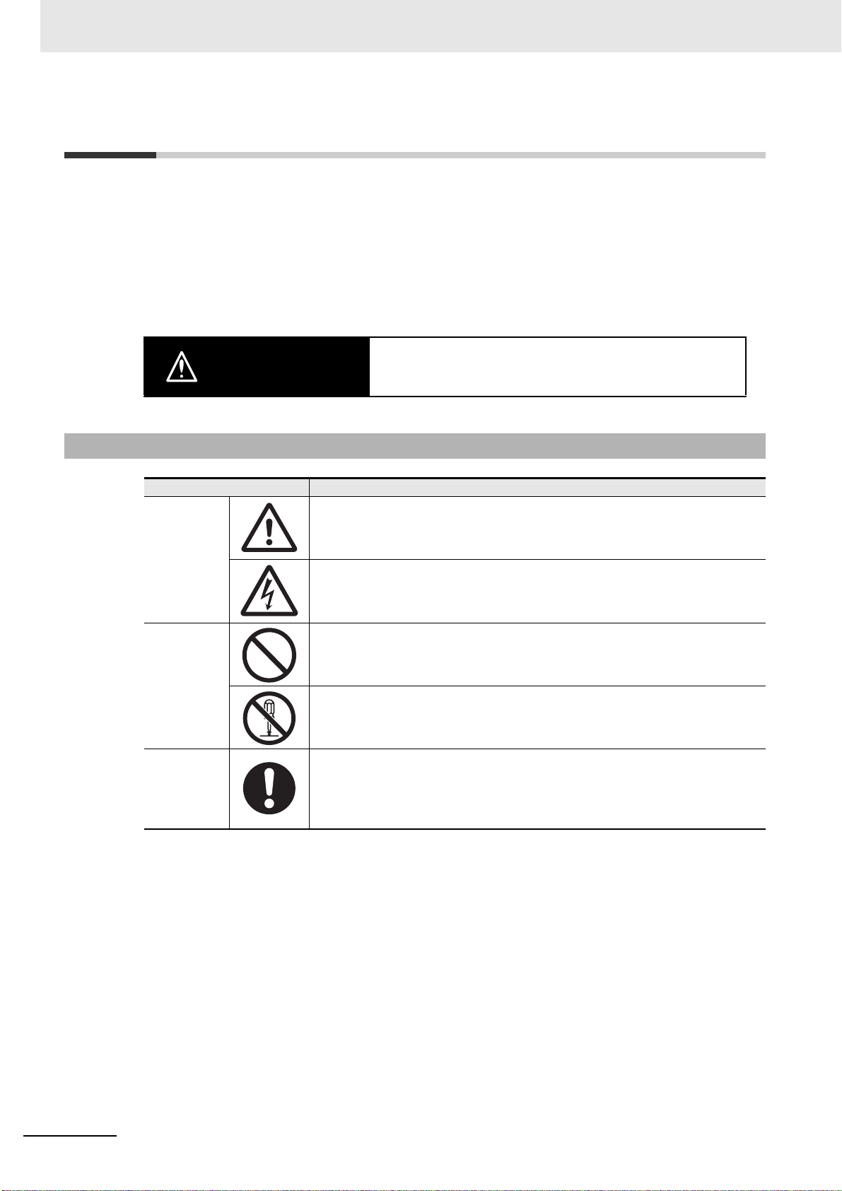
Symbols
Symbol Meaning
Caution
Prohibition
Mandatory
Caution
• General Caution
Indicates non-specific general cautions, warnings, and dangers.
• Electrical Shock Caution
Indicates possibility of electric shock under specific conditions.
• General Prohibition
Indicates non-specific general prohibitions.
• Disassembly Prohibition
Indicates prohibitions when there is a possibility of injury, such as from
electric shock, as the result of disassembly.
• General Caution
Indicates non-specific general cautions, warnings, and dangers.
4
E5@C Digital Temperature Controllers User’s Manual (H174)
Page 7
Safety Precautions
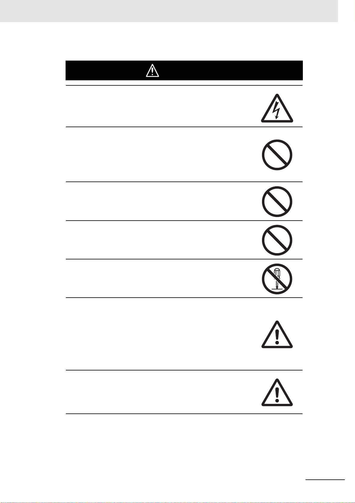
CAUTION
Minor injury due to electric shock may occasionally occur.
Do not touch the terminals while power is being supplied.
Electric shock, fire, or malfunction may occasionally occur.
Do not allow metal objects, conductors, cuttings from installation
work, moisture, or other foreign matter to enter the Digital Controller,
the Setup Tool ports, or between the pins on the connectors on the
Setup Tool cable.
Attach the cover to the front-panel Setup Tool port whenever you
are not using it to prevent foreign objects from entering the port.
Safety Precautions
Minor injury from explosion may occasionally occur.
Do not use the product where subject to flammable or explosive gas.
Fire may occasionally occur.
Do not allow dirt or other foreign objects to enter a Setup Tool port,
or between the pins on the connectors on the Setup Tool cable.
Minor electric shock, fire, or malfunction may occasionally occur.
Never disassemble, modify, or repair the product or touch any of the
internal parts.
CAUTION - Risk of Fire and Electric Shock
(a) This product is UL listed as Open Type Process Control
Equipment. It must be mounted in an enclosure that does not
allow fire to escape externally.
(b) More than one disconnect switch may be required to
de-energize the equipment before servicing.
(c) Signal inputs are SELV, limited energy.
(d) Caution: To reduce the risk of fire or electric shock, do not
interconnect the outputs of different Class 2 circuits.
If the output relays are used past their life expectancy, contact fusing
or burning may occasionally occur.
Always consider the application conditions and use the output relays
within their rated load and electrical life expectancy. The life
expectancy of output relays varies considerably with the output load
and switching conditions.
*1 An SELV (separated extra-low voltage) system is one with a power supply that has double or reinforced
insulation between the primary and the secondary circuits and has an output voltage of 30 V r.m.s. max.
and 42.4 V peak max. or 60 VDC max.
*2 A class 2 circuit is one tested and certified by UL as having the current and voltage of the secondary output
restricted to specific levels.
*1
*2
E5@C Digital Temperature Controllers User’s Manual (H174)
5
Page 8
Safety Precautions
If you replace only the Main Unit of the E5DC or E5DC-B, check the
condition of the Terminal Unit.
If corroded terminals are used, contact failure in the terminals may
cause the temperature inside the Digital Controller to increase,
possibly resulting in fire.
If the terminals are corroded, replace the Terminal Unit as well.
Loose screws may occasionally result in fire.
Tighten the terminal screws to the specified torque of 0.43 to
0.58 N·m.*
Set the parameters of the product so that they are suitable for the
system being controlled. If they are not suitable, unexpected
operation may occasionally result in property damage or accidents.
CAUTION
A malfunction in the Digital Controller may occasionally make control
operations impossible or prevent alarm outputs, resulting in property
damage. To maintain safety in the event of malfunction of the Digital
Controller, take appropriate safety measures, such as installing a
monitoring device on a separate line.
* The specified torque is 0.5 N·m for the E5CC-U.
6
E5@C Digital Temperature Controllers User’s Manual (H174)
Page 9
Precautions for Safe Use
Be sure to observe the following precautions to prevent operation failure, malfunction, or adverse
affects on the performance and functions of the product. Not doing so may occasionally result in unexpected events. Use the product within specifications.
• The product is designed for indoor use only. Do not use or store the product outdoors or in any of the
following places.
Places directly subject to heat radiated from heating equipment.
Places subject to splashing liquid or oil atmosphere.
Places subject to direct sunlight.
Places subject to dust or corrosive gas (in particular, sulfide gas and ammonia gas).
Places subject to intense temperature change.
Places subject to icing and condensation.
Places subject to vibration and large shocks.
• Use and store the Digital Controller within the rated ambient temperature and humidity.
Gang-mounting two or more Digital Controllers, or mounting Digital Controllers above each other
may cause heat to build up inside the Digital Controllers, which will shorten their service life. In such
a case, use forced cooling by fans or other means of air ventilation to cool down the Digital
Controllers.
• To allow heat to escape, do not block the area around the Digital Controller. Do not block the
ventilation holes on the Digital Controller.
• Be sure to wire properly with the correct signal name and polarity of terminals.
• To connect bare wires, use copper stranded or solid wires.
Use the wire sizes and stripping lengths given in the following table to prevent smoking and firing of
the wiring material.
Precautions for Safe Use
Recommended Wires
Model Recommended wires Stripping length
E5CC, E5EC, E5AC, E5DC, or E5GC
(models with screw terminal blocks)
E5GC (models with screwless clamp
terminal blocks)
E5CC-U (plug-in models)
E5@C-B (models with Push-In Plus
terminal blocks) *1
*1 Use Ferrules with UL certification (R/C).
AWG24 to AWG18 (0.21 to 0.82 mm
Copper stranded or solid wires
AWG24 to AWG14 (0.21 to 2.08 mm
Copper stranded or solid wires
0.25 to 1.5 mm
AWG16)
Copper stranded or solid wires
2
(equivalent to AWG24 to
2
2
Connect only one wire to each terminal.
Use the specified size of crimped terminals to wire the E5CC, E5EC, E5AC, E5DC, and E5GC
(models with screw terminal blocks) as well as the E5CC-U (plug-in models).
6 to 8 mm
)
8 to 12 mm
5 to 6 mm
)
With ferrules: 10 mm
Without ferrules: 8 mm
E5@C Digital Temperature Controllers User’s Manual (H174)
7
Page 10

Precautions for Safe Use
Crimp Terminal Sizes
Model Crimp terminal size
E5CC, E5EC, E5AC, E5DC, or E5GC
(models with screw terminal blocks)
E5CC-U (plug-in models) M3.5, Width: 7.2 mm max.
For the E5@D-B (models with Push-In Plus terminal blocks), connect only one wire to each terminal.
For the E5@C (models with screw terminals), you can connect up to two wires of the same size and
type, or two crimped terminals, to a single terminal.
When connecting two wires to one terminal on the E5GC (models with screwless clamp terminal
blocks), use two crimped ferrules with a diameter of 0.8 to 1.4 mm and an exposed conductor length
of 8 to 12 mm.
*1 The E5GC (models with screwless clamp terminal blocks) underwent UL testing with one stranded wire
connected.
• Do not wire the terminals that are not used.
• To avoid inductive noise, keep the wiring for the Digital Controller's terminal block away from power
cables that carry high voltages or large currents. Also, do not wire power lines together with or
parallel to Digital Controller wiring. Using shielded cables and using separate conduits or ducts is
recommended.
Attach a surge suppressor or noise filter to peripheral devices that generate noise (in particular,
motors, transformers, solenoids, magnetic coils or other equipment that have an inductance
component).
When a noise filter is used at the power supply, first check the voltage or current, and attach the
noise filter as close as possible to the Digital Controller.
Allow as much space as possible between the Digital Controller and devices that generate powerful
high frequencies (high-frequency welders, high-frequency sewing machines, etc.) or surge.
• Use the Digital Controller within the rated load and power supply.
• Make sure that the rated voltage is attained within 2 seconds of turning ON the power using a switch
or relay contact. If the voltage is applied gradually, the power may not be reset or output malfunctions
may occur.
• Make sure that the Digital Controller has 30 minutes or more to warm up after turning ON the power
before starting actual control operations to ensure the correct temperature display.
• When executing self-tuning, turn ON power for the load (e.g., heater) at the same time as or before
supplying power to the Digital Controller. If power is turned ON for the Digital Controller before
turning ON power for the load, self-tuning will not be performed properly and optimum control will not
be achieved.
• A switch or circuit breaker must be provided close to the Digital Controller. The switch or circuit
breaker must be within easy reach of the operator, and must be marked as a disconnecting means
for the Digital Controller.
• Wipe off any dirt from the Digital Controller with a soft dry cloth. Never use thinners, benzine, alcohol,
or any cleaners that contain these or other organic solvents. Deformation or discoloration may occur.
• Design the system (e.g., control panel) considering the 2 seconds of delay in setting the Digital
Controller’s output after the power supply is turned ON.
• The output will turn OFF when you move to the Initial Setting Level. Take this into consideration when
performing control.
• The number of non-volatile memory write operations is limited. Therefore, use RAM write mode when
frequently overwriting data, e.g., through communications.
• Always touch a grounded piece of metal before touching the Digital Controller to discharge static
electricity from your body.
• Use suitable tools when taking the Digital Controller apart for disposal. Sharp parts inside the Digital
Controller may cause injury.
*1
M3, Width: 5.8 mm max.
8
E5@C Digital Temperature Controllers User’s Manual (H174)
Page 11

Precautions for Safe Use
• For compliance with Lloyd’s standards, the E5CC, E5CC-U, E5CC-B, E5EC, E5EC-B, E5AC, and
E5DC must be installed under the conditions that are specified in Shipping Standards.
• On models with two Setup Tool ports (E5EC, E5EC-B, E5AC, E5DC, E5DC-B, and E5GC), do not
connect cables to both ports at the same time. The Digital Controller may be damaged or may
malfunction.
• Do not exceed the communications distance that is given in the specifications and use the specified
communications cable.
• Do not turn the power supply to the Digital Controller ON or OFF while the USB-Serial Conversion
Cable is connected. The Digital Controller may malfunction.
• Use wires with heat resistance of 75°C min to wire the terminals because the maximum terminal
temperature is 75°C.
• Do not bend the communications cables past their natural bending radius. Do not pull on the
communications cables.
• For the E5DC and E5DC-B, when you attach the Main Unit to the Terminal Unit, make sure that the
hooks on the Main Unit are securely inserted into the Terminal Unit.
• For the E5CC-U, when you attach the Main Unit to the socket, make sure that the hooks on the
socket are securely inserted into the Main Unit.
• Install the DIN Track vertically to the ground.
• For the E5DC and E5DC-B, always turn OFF the power supply before connecting the Main Unit to or
disconnecting the Main Unit from the Terminal Unit, and never touch nor apply shock to the terminals
or electronic components. When connecting or disconnecting the Main Unit, do not allow the
electronic components to touch the case.
• Observe the following precautions when you remove the terminal block or pull out (draw out) the
interior of the E5GC.
• Follow the procedure given in Drawing Out the Interior Body of the E5GC to Replace It on page
2-21 of this manual.
• Turn OFF the power supply before you start and never touch nor apply shock to the terminals or
electric components.
When you insert the interior body of the Digital Controller, do not allow the electronic components
to touch the case.
• Check for any corrosion on the terminals.
• When you insert the interior body into the rear case, confirm that the hooks on the top and bottom
are securely engaged with the case.
• Observe the following precautions when wiring the E5@C-B.
@
• Follow the procedures given in E5
of this manual.
• Do not wire anything to the release holes.
• Do not tilt or twist a flat-blade screwdriver while it is inserted into a release hole on the terminal
block. The terminal block may be damaged.
• Insert a flat-blade screwdriver into the release holes at an angle. The terminal block may be
damaged if you insert the screwdriver straight in.
• Do not allow the flat-blade screwdriver to fall out while it is inserted into a release hole.
• Do not bend a wire past its natural bending radius or pull on it with excessive force. Doing so may
cause the wire to break.
• Do not use crossover wiring to the E5CC-B or E5EC-B except for the input power supply and
communications.
• Do not use crossover wiring to the E5DC-B.
C-B (Models with Push-In Plus Terminal Blocks) on page 2-58
E5@C Digital Temperature Controllers User’s Manual (H174)
9
Page 12

Installation Precautions
Installation Precautions
Service Life
Use the Digital Controller within the following temperature and humidity ranges:
Temperature: −10 to 55°C (with no icing or condensation), Humidity: 25% to 85%
If the Digital Controller is installed inside a control board, the ambient temperature must be kept to
under 55°C, including the temperature around the Digital Controller.
The service life of electronic devices like Digital Controllers is determined not only by the number of
times the relay is switched but also by the service life of internal electronic components. Component
service life is affected by the ambient temperature: the higher the temperature, the shorter the
service life and, the lower the temperature, the longer the service life. Therefore, the service life can
be extended by lowering the temperature of the Digital Controller.
When two or more Digital Controllers are mounted horizontally close to each other or vertically next
to one another, the internal temperature will increase due to heat radiated by the Digital Controllers
and the service life will decrease. In such a case, use forced cooling by fans or other means of air
ventilation to cool down the Digital Controllers. When providing forced cooling, however, be careful
not to cool down the terminals sections alone to avoid measurement errors.
Ensuring Measurement Accuracy
When extending or connecting the thermocouple lead wire, be sure to use compensating wires that
match the thermocouple types.
When extending or connecting the lead wire of the platinum resistance thermometer, be sure to use
wires that have low resistance and keep the resistance of the three lead wires the same.
Mount the Digital Controller so that it is horizontally level.
If the measurement accuracy is low, check to see if input shift has been set correctly.
Resistance to Water (E5CC, E5CC-B, E5EC, E5EC-B, E5AC, and E5GC Only)
The degree of protection is as shown below. Sections without any specification on their degree of
protection or those with IP@0 are not waterproof.
Front panel: IP66
Rear case: IP20, Terminal section: IP00
When waterproofing is required, insert the Waterproof Packing on the backside of the front panel.
Keep the Port Cover on the front-panel Setup Tool port of the E5EC, E5EC-B, and E5AC securely
closed. The degree of protection when the Waterproof Packing is used is IP66. To maintain an IP66
degree of protection, the Waterproof Packing and the Port Cover for the front-panel Setup Tool port
must be periodically replaced because they may deteriorate, shrink, or harden depending on the
operating environment. The replacement period will vary with the operating environment. Check the
required period in the actual application. Use 3 years or sooner as a guideline. If the Waterproof
Packing and Port Cover are not periodically replaced, waterproof performance may not be
maintained.
10
E5@C Digital Temperature Controllers User’s Manual (H174)
Page 13

Precautions for Operation
• When using self-tuning, turn ON power for the load (e.g., heater) at the same time as or before
supplying power to the Digital Controller. If power is turned ON for the Digital Controller before
turning ON power for the load, self-tuning will not be performed properly and optimum control will not
be achieved. When starting operation after the Digital Controller has warmed up, turn OFF the power
and then turn it ON again at the same time as turning ON power for the load. (Instead of turning the
Digital Controller OFF and ON again, switching from STOP Mode to RUN Mode can also be used.)
• Avoid using the Digital Controller in places near a radio, television set, or wireless installing. The
Digital Controller may cause radio disturbance for these devices.
Shipping Standards
Precautions for Operation
The E5CC, E5CC-U, E5CC-B, E5EC, E5EC-B, E5AC, and E5DC comply with Lloyd’s standards. For
compliance with these standards, install the Digital Controller in an installation location that meets the
application conditions. Also, insert the Waterproof Packing on the Digital Controller.
Application Conditions
Installation Location
The E5CC, E5CC-U, E5CC-B, E5EC, E5EC-B, E5AC, and E5DC are applicable to installation category
ENV1 or ENV2 of Lloyd’s standards. The installation environment must be equipped with air conditioning. The installation environment must be equipped with air conditioning. They cannot be used on the
bridge or decks, or in a location subject to strong vibration.
E5@C Digital Temperature Controllers User’s Manual (H174)
11
Page 14
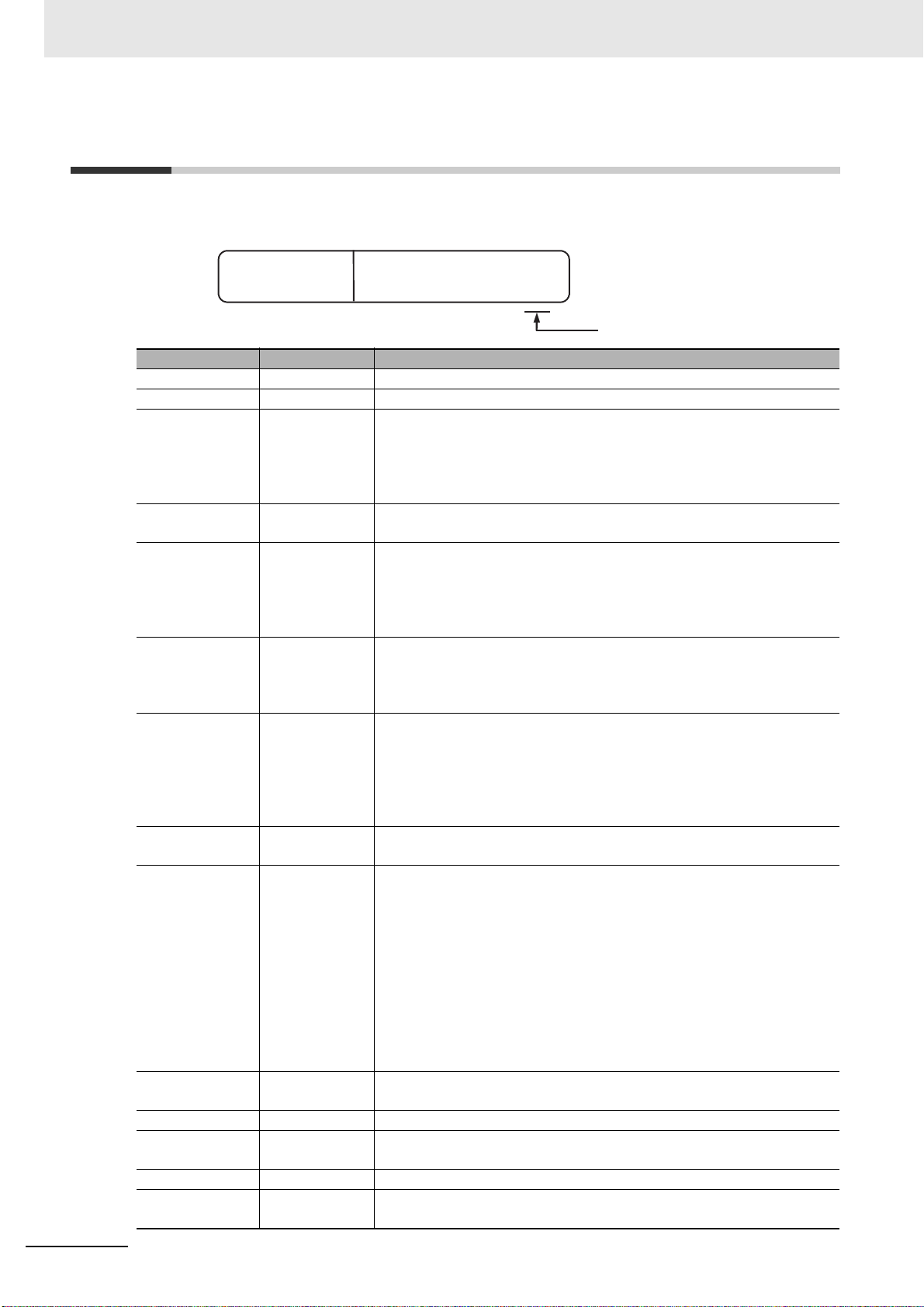
Preparations for Use
Preparations for Use
Be sure to thoroughly read and understand the manual provided with the product, and check the following points.
Timing Check point Details
Purchasing
the product
Setting the
Unit
Wiring Terminal wiring Do not subject the terminal screws to excessive stress (force) when
Operating
environment
Product
appearance
Product model and
specifications
Product installation
location
Power supply
inputs
Ambient
temperature
Vibration and
shock
Foreign particles Install the product in a location that is not subject to liquid or foreign
After purchase, check that the product and packaging are not dented or
otherwise damaged. Damaged internal parts may prevent optimum control.
Make sure that the purchased product meets the required specifications.
Provide sufficient space around the product for heat dissipation. Do not
block the vents on the product.
tightening them.
Make sure that there are no loose screws after tightening terminal screws to
the specified torque of 0.43 to 0.58 N·m.
Be sure to confirm the polarity for each terminal before wiring the terminal
block and connectors.
For the E5@C-B (models with Push-In Plus terminal blocks), do not attempt
to wire anything to the release holes.
For the E5CC-B or E5DC-B (models with Push-In Plus terminal blocks), use
crossover wiring only for the input power supply and communications. Do
not exceed the maximum number of Digital Controllers given below if you
use crossover wiring for the input power supply.
100 to 240 VAC Controllers: 16 max.
24 VAC/VDC Controllers: 8 max.
Do not perform crossover wiring for the E5DC-B (models with Push-in Plus
Terminal Blocks).
Wire the power supply inputs correctly. Incorrect wiring will result in
damage to the internal circuits.
The ambient operating temperature for the Digital Controller is −10 to
*2
55°C
(with no condensation or icing).
To extend the service life of the product, install it in a location with an
ambient temperature as low as possible. In locations exposed to high
temperatures, if necessary, cool the products using a fan or other cooling
method.
Check whether the standards related to shock and vibration are satisfied at
the installation environment. (Install the product in locations where the
contactors will not be subject to vibration or shock.)
particles entering the product.
*1
12
*1 The specified torque is 0.5 N·m for the E5CC-U.
*2 When two or more E5GC Digital Controllers are mounted, make sure that the ambient temperature of the
Digital Controller does not exceed the allowable operating temperature range given below.
Horizontal group mounting: −10 to 55°C
Vertical group mounting of two Digital Controllers: −10 to 45°C
Vertical group mounting of three or more Digital Controllers: −10 to 40°C
For vertical group mounting, use Digital Controllers with screwless clamp terminal blocks.
For E5EC models with two control outputs (QQ, QR, CQ, RR, CC, or PR) and 011, 012, 013, or 014 options,
the ambient temperature for group mounting must be 45°C max.
E5@C Digital Temperature Controllers User’s Manual (H174)
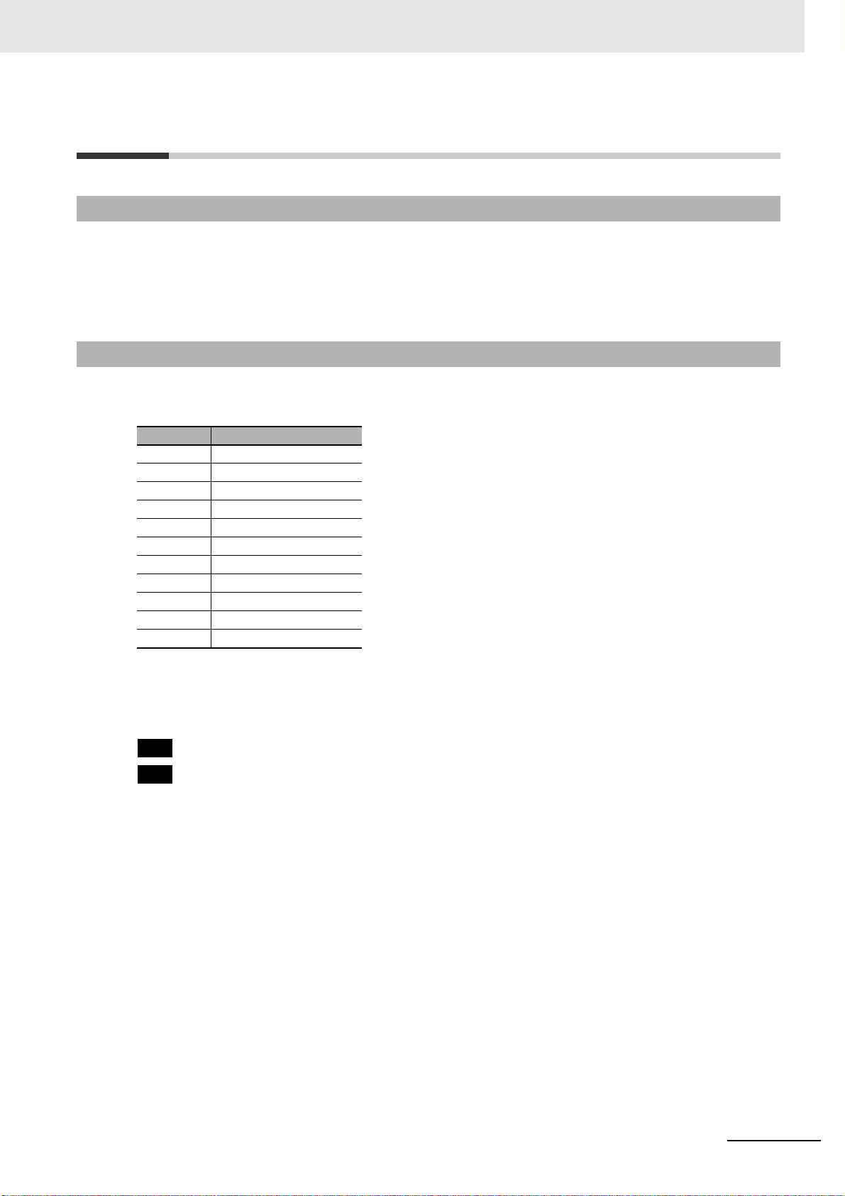
Page 15
Versions
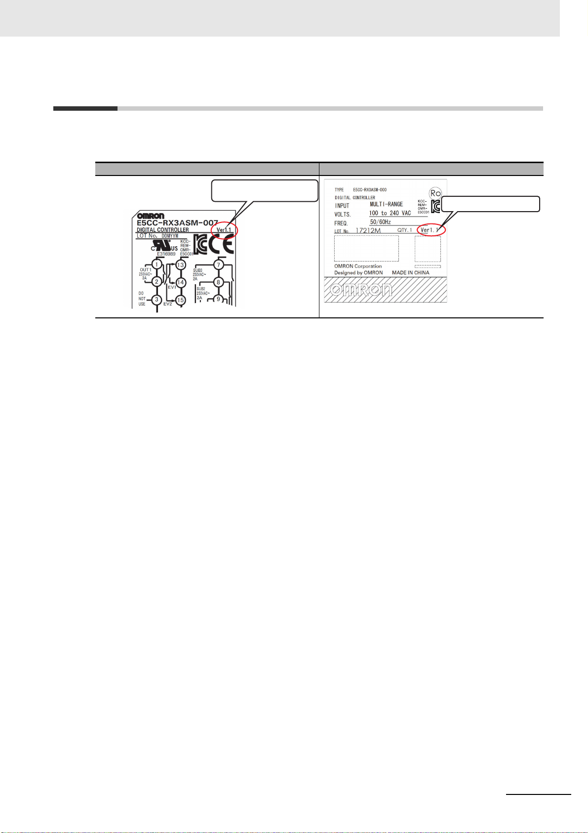
The version is given here.
Check the version on the nameplate on the E5@C Digital Controller or on the label on the packing box.
If the version is not given, the version of the E5@C Digital Controller is version 1.0.
Versions
Product nameplate Package label
The version is given here.
E5@C Digital Temperature Controllers User’s Manual (H174)
13
Page 16
Revision History
H174-E1-14
Revision code
Cat. No.
Revision History
A manual revision code appears as a suffix to the catalog number on the front cover of the manual.
Revision code Date Revised content
01 December 2011 Original production
02 January 2012 Page 9: Made correction in Precautions for Safe Use.
03 December 2012 • Made changes accompanying the addition of programless
04 July 2013 • Added version 1.0 of the E5DC.
05 December 2013 • Added E5CC-U.
06 April 2014 • Added version 2.2 of the E5GC.
07 July 2014 • Added E5DC-U.
08 August 2014 • Added the Valve Opening Monitor Selection and FB Moving Average
09 June 2015 Page 4-46: Changed figure for burnout at bottom of page.
10 March 2016 • Added information on version 2.1 of the E5@C-B.
11 July 2016 • Corrected mistakes and added explanations.
12 October 2017
13 March 2018 • Added precautions for wiring of screw terminal block types.
14 April 2019 • Added information on version 2.2 of the E5DC-B.
communications and component communications (version 1.1).
• Added E5EC/E5AC Digital Controllers with position-proportional control
and E5AC Digital Controllers. (version 2.0).
• Corrected mistakes.
• Corrected mistakes.
• Improved autotuning for heating/cooling control.
• Added Mitsubishi FX-series PLCs and Keyence PLCs to information on
programless communications (version 2.1).
• Corrected mistakes.
• Added an analog input type and simple transfer function for the
E5CC-U (version 2.2).
• Corrected mistakes.
• Added simple transfer function and status message function to the
E5DC (version 2.2).
• Added seconds as the unit for the soak time (version 2.2).
• Added Lloyd’s standards for the E5DC.
• Corrected mistakes.
Count parameters for E5EC/E5AC-PR@-8@@ (version 2.2).
Pages 5-55 and 6-89: Added note *5 and references to it in table.
Page 5-60: Changed level to Operation Level for Remote SP Monitor.
Page 5-61: Changed level in first sentence of Remote SP Monitor to
Operation Level.
Page 6-5: Added note below table for Changed Parameters Only.
Page 6-6: Added note above table for Parameter Mask Enable.
Page 6-30: Changed conditions given to right of “Manual Reset Value.”
Page 6-56: Added note at bottom of page.
Page 6-70: Added note above table.
Page 6-93: Added note above table in Display Refresh Period.
• Corrected mistakes.
• Adde
d E5@C-B Digital Controllers with current outputs.
• Corrected mistakes.
• Corrected mistakes.
14
E5@C Digital Temperature Controllers User’s Manual (H174)
Page 17
Conventions Used in This Manual
000
800
Conventions Used in This Manual
Model Notation
“E5@C” is used to indicate information that is the same for the E5CC, E5CC-U, E5CC-B, E5EC,
E5EC-B, E5AC, E5DC, E5DC-B, and E5GC Digital Controllers. “E5@C-B” is used to indicate information that is the same for the E5CC-B, E5EC-B, and E5DC-B Digital Controllers. “E5EC/E5AC-PR@” or
“Position-proportional Models” indicates the Digital Controllers with position-proportional control. “Standard Models” indicates other Digital Controllers.
Meanings of Abbreviations
The following abbreviations are used in parameter names, figures, and other descriptions. These
abbreviations mean the following:
Symbol Term
PV Process value
SP Set point
SV Set value
AT Auto-tuning
ST Self-tuning
EU Engineering unit*
LBA Loop burnout alarm
HB Heater burnout
HS Heater short
RSP Remote SP
LSP Local SP
* “EU” stands for Engineering Unit. EU is used as the minimum unit for engineering units such as °C, m, and g.
The size of the EU depends on the input type. For example, when the input temperature setting range is −200
to 1,300°C, 1 EU is 1°C, and when the input temperature setting range is −20.0 to 500.0°C, 1 EU is 0.1°C.
For analog inputs, the size of the EU depends on the decimal point position of the scaling setting, and 1 EU is
the minimum scaling unit.
: Indicates items that can be used only with the E5@C-@-0@@.
: Indicates items that can be used only with the E5@C-@-8@@.
E5@C Digital Temperature Controllers User’s Manual (H174)
15
Page 18
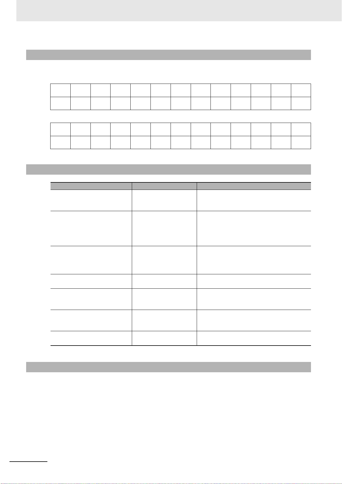
Conventions Used in This Manual
How to Read Display Symbols
The following tables show the correspondence between the symbols displayed on the displays and
alphabet characters.
abcdefghijklm
ABCDEFGH I J KLM
nopqrstuVwxyz
NOPQRS T UVWX Y Z
How This Manual is Organized
Goal Related sections Contents
Learning about the
appearance, features,
functions, and model numbers
Setting up the E5@C Section 2 Preparations This section describes the steps that are
Learning the basic procedures
from turning ON the power
supply to starting actual
operation
Learning the basic operating
methods
Learning advanced operating
methods
Calibrating the E5@C Section 7 User Calibration This section describes the procedures that you
Learning the specifications
and parameters of the E5@C
Section 1 Introduction ---
required before turning ON the power supply
(including installation, terminal usage, wiring,
and isolation/insulation block diagram). It also
describes how to use the Setup Tool ports.
Section 3 Part Names and
Basic Procedures
Section 4 Basic Operation
Section 6 Parameters
Section 5 Advanced
Operations
Section 6 Parameters
Appendices ---
This section serves as a basic tutorial for
first-time users of the E5@C.
These sections describe basic operating
methods.
These sections describe advanced operating
methods.
can use to calibrate the sensor or transfer
output of the E5@C.
Related Manuals
Also refer to the E5
communications.
16
@
C Digital Controllers Communications Manual (Cat. No. H175) for information on
E5@C Digital Temperature Controllers User’s Manual (H174)
Page 19
1
2
3
4
5
6
7
1
2
3
4
5
6
7
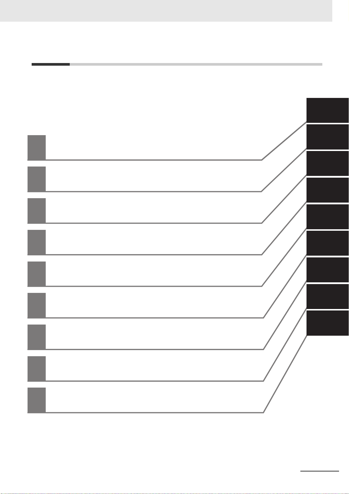
Introduction
Preparations
Part Names and Basic Procedures
Basic Operation
Advanced Operations
Parameters
User Calibration
A
A
Appendices
I
I
Index
Sections in this Manual
Sections in this Manual
E5@C Digital Temperature Controllers User’s Manual (H174)
17
Page 20

CONTENTS
Preface .......................................................................................................................1
Terms and Conditions Agreement...........................................................................2
Warranty, Limitations of Liability ................................................................................................................... 2
Application Considerations ........................................................................................................................... 3
Disclaimers ................................................................................................................................................... 3
Safety Precautions.................................................................................................... 4
Definition of Precautionary Information ......................................................................................................... 4
Symbols ....................................................................................................................................................... 4
Precautions for Safe Use..........................................................................................7
Installation Precautions..........................................................................................10
Precautions for Operation ......................................................................................11
Shipping Standards ................................................................................................11
Preparations for Use...............................................................................................12
Versions ...................................................................................................................13
Revision History......................................................................................................14
Conventions Used in This Manual.........................................................................15
Model Notation ............................................................................................................................................ 15
Meanings of Abbreviations .......................................................................................................................... 15
How to Read Display Symbols .................................................................................................................... 16
How This Manual is Organized ................................................................................................................... 16
Related Manuals ......................................................................................................................................... 16
Sections in this Manual ..........................................................................................17
Section 1 Introduction
1-1 Appearance, Features, and Functions of the E5@C............................................................. 1-2
1-1-1 Appearance.................................................................................................................................1-2
1-1-2 Features...................................................................................................................................... 1-2
1-1-3 Main Functions............................................................................................................................1-3
1-2 I/O Configuration and Model Number Legend ...................................................................... 1-5
1-2-1 I/O Configuration......................................................................................................................... 1-5
1-2-2 Model Number Legends.............................................................................................................. 1-6
Section 2 Preparations
2-1 Installation................................................................................................................................ 2-2
2-1-1 Dimensions (Unit: mm)................................................................................................................2-2
2-1-2 Panel Cutout (Unit: mm).............................................................................................................. 2-6
2-1-3 Mounting ..................................................................................................................................... 2-9
18
E5@C Digital Temperature Controllers User’s Manual (H174)
Page 21

2-2 Using the Terminals .............................................................................................................. 2-24
2-2-1 E5CC Terminal Block Wiring Example ..................................................................................... 2-24
2-2-2 E5CC-U Terminal Block Wiring Example ................................................................................. 2-29
2-2-3 E5CC-B Terminal Block Wiring Example.................................................................................. 2-32
2-2-4 E5EC/E5AC Terminal Block Wiring Example ........................................................................... 2-36
2-2-5 E5EC-B Terminal Block Wiring Example.................................................................................. 2-41
2-2-6 E5DC Terminal Block Wiring Example ..................................................................................... 2-46
2-2-7 E5DC-B Terminal Block Wiring Example.................................................................................. 2-49
2-2-8 E5GC Terminal Block Wiring Example..................................................................................... 2-52
2-2-9 Precautions when Wiring.......................................................................................................... 2-55
2-2-10 Wiring........................................................................................................................................ 2-61
2-3 Insulation Block Diagrams ................................................................................................... 2-73
2-4 Using the Setup Tool Port ...................................................................................................2-76
2-4-1 Procedure ................................................................................................................................. 2-76
2-4-2 Connection Method................................................................................................................... 2-76
2-4-3 Installing the Driver................................................................................................................... 2-83
Section 3 Part Names and Basic Procedures
3-1 Basic Application Flow ........................................................................................................... 3-2
3-2 Power ON ................................................................................................................................. 3-3
3-3 Part Names, Part Functions, and Setting Levels .................................................................. 3-4
3-3-1 Part Names and Functions ......................................................................................................... 3-4
3-3-2 Entering Numeric Values............................................................................................................ 3-9
3-3-3 Setting Levels ........................................................................................................................... 3-10
3-4 Procedures after Turning ON the Power Supply ................................................................ 3-13
3-4-1 Basic Flow of Operations.......................................................................................................... 3-13
3-4-2 Basic Procedure ....................................................................................................................... 3-13
Section 4 Basic Operation
4-1 Moving between Setting Levels ............................................................................................. 4-3
4-1-1 Moving to the Initial Setting Level............................................................................................... 4-3
4-1-2 Moving to the Adjustment Level.................................................................................................. 4-4
4-1-3 Moving to the Protect Level ........................................................................................................ 4-4
4-1-4 Moving to the Advanced Function Setting Level......................................................................... 4-5
4-1-5 Moving to the Communications Setting Level............................................................................. 4-7
4-2 Initial Setting Examples .......................................................................................................... 4-8
4-3 Setting the Input Type ........................................................................................................... 4-11
4-3-1 Input Type................................................................................................................................. 4-11
4-4 Selecting the Temperature Unit ........................................................................................... 4-13
4-4-1 Temperature Unit...................................................................................................................... 4-13
4-5 Selecting PID Control or ON/OFF Control
(Not Supported for Position-proportional Models.) ........................................................... 4-14
4-6 Setting Output Specifications .............................................................................................. 4-15
4-6-1 Control Periods (Not Supported for Position-proportional Models.).......................................... 4-15
4-6-2 Direct and Reverse Operation .................................................................................................. 4-15
4-6-3 Assigned Output Functions (Assigning Control Outputs Is Not Supported for
Position-proportional Models.) .................................................................................................4-16
4-6-4 Auxiliary Output Opening or Closing in Alarm .......................................................................... 4-19
4-7 Setting the Set Point (SP) ..................................................................................................... 4-20
4-7-1 Changing the SP....................................................................................................................... 4-20
E5@C Digital Temperature Controllers User’s Manual (H174)
19
Page 22

4-8 Using ON/OFF Control (Not Supported for Position-proportional Models.) .................... 4-21
4-8-1 ON/OFF Control........................................................................................................................ 4-21
4-8-2 Settings .....................................................................................................................................4-22
4-9 Determining PID Constants(AT, ST, Manual Setup) ........................................................... 4-24
4-9-1 AT (Auto-tuning)........................................................................................................................4-24
4-9-2 ST (Self-tuning) (Not Supported for Position-proportional Models.)..........................................4-27
4-9-3 RT (Robust Tuning) (Used for AT or ST.) ................................................................................4-28
4-9-4 Manual Setup............................................................................................................................4-30
4-10 Alarm Outputs........................................................................................................................ 4-32
4-10-1 Alarm Types..............................................................................................................................4-32
4-10-2 Alarm Values............................................................................................................................. 4-35
4-11 Alarm Hysteresis ................................................................................................................... 4-38
4-11-1 Standby Sequence.................................................................................................................... 4-38
4-11-2 Alarm Latch...............................................................................................................................4-39
4-12 Using Heater Burnout (HB) and Heater Short (HS) Alarms
(Not Supported for Position-proportional Models.)............................................................ 4-40
4-12-1 HB Alarm................................................................................................................................... 4-40
4-12-2 HS Alarm................................................................................................................................... 4-42
4-12-3 Installing Current Transformers (CT) ........................................................................................4-44
4-12-4 Calculating Detection Current Values .......................................................................................4-46
4-12-5 Application Examples................................................................................................................ 4-46
4-13 Customizing the PV/SP Display ........................................................................................... 4-50
4-13-1 PV/SP Display Selections .........................................................................................................4-50
Section 5 Advanced Operations
5-1 Shifting Input Values............................................................................................................... 5-3
5-2 Setting Scaling Upper and Lower Limits for Analog Inputs ................................................ 5-5
5-3 Executing Heating/Cooling Control (Not Supported for Position-proportional Models.) .... 5-7
5-3-1 Heating/Cooling Control.............................................................................................................. 5-7
5-4 Using Event Inputs ................................................................................................................ 5-11
5-4-1 Event Input Settings..................................................................................................................5-11
5-4-2 How to Use the Multi-SP Function ............................................................................................ 5-11
5-4-3 Operation Commands Other than Multi-SP .............................................................................. 5-12
5-5 Setting the SP Upper and Lower Limit Values.................................................................... 5-15
5-5-1 Set Point Limiter........................................................................................................................5-15
5-5-2 Setting....................................................................................................................................... 5-16
5-6 Using the SP Ramp Function to Limit the SP Change Rate .............................................. 5-17
5-6-1 SP Ramp...................................................................................................................................5-17
5-7 Using the Key Protect Level ................................................................................................. 5-19
5-7-1 Protection.................................................................................................................................. 5-19
5-7-2 Entering the Password to Move to the Protect Level ...............................................................5-20
5-8 Displaying Only Parameters That Have Been Changed..................................................... 5-22
5-8-1 Displaying Changed Parameters ..............................................................................................5-22
5-9 OR Output of Alarms ............................................................................................................. 5-24
5-9-1 Integrated Alarm........................................................................................................................ 5-24
5-10 Alarm Delays .......................................................................................................................... 5-26
5-10-1 Alarm Delays............................................................................................................................. 5-26
5-11 Loop Burnout Alarm (Not Supported for Position-proportional Models.)........................ 5-28
5-11-1 Loop Burnout Alarm (LBA)........................................................................................................5-28
5-12 Performing Manual Control .................................................................................................. 5-32
5-12-1 Manual MV................................................................................................................................5-32
20
E5@C Digital Temperature Controllers User’s Manual (H174)
Page 23

5-13 Using the Transfer Output for the Process Value, Set Point, or other Data .................... 5-36
5-13-1 Transfer Output Function.......................................................................................................... 5-36
5-13-2 Simple Transfer Output Function.............................................................................................. 5-39
5-14 Using the Simple Program Function .................................................................................. 5-42
5-14-1 Simple Program Function ......................................................................................................... 5-42
5-14-2 Operation at the Program End.................................................................................................. 5-45
5-14-3 Application Example Using a Simple Program ......................................................................... 5-47
5-15 Output Adjustment Functions.............................................................................................. 5-48
5-15-1 Output Limits............................................................................................................................. 5-48
5-15-2 MV at Stop ............................................................................................................................... 5-48
5-15-3 MV at PV Error ......................................................................................................................... 5-49
5-16 Using the Extraction of Square Root Parameter ............................................................... 5-51
5-16-1 Extraction of Square Roots....................................................................................................... 5-51
5-17 Setting the Width of MV Variation ....................................................................................... 5-53
5-17-1 MV Change Rate Limit.............................................................................................................. 5-53
5-18 Setting the PF Key ................................................................................................................. 5-55
5-18-1 PF Setting (Function Key) ........................................................................................................ 5-55
5-19 Displaying PV/SV Status ....................................................................................................... 5-58
5-19-1 PV and SV Status Display Functions........................................................................................5-58
5-20 Using a Remote SP................................................................................................................ 5-60
5-21 Controlling Valves (Can Be Used with a Position-proportional Model) ........................... 5-62
5-22 Logic Operations .................................................................................................................. 5-65
5-22-1 The Logic Operation Function (CX-Thermo) ............................................................................ 5-65
5-22-2 Using Logic Operations ............................................................................................................ 5-65
5-22-3 Using Status Display Messages............................................................................................... 5-73
5-23 Initializing Settings ................................................................................................................ 5-75
Section 6 Parameters
6-1 Conventions Used in this Section ......................................................................................... 6-2
6-2 Protect Level ............................................................................................................................ 6-3
6-3 Operation Level ....................................................................................................................... 6-7
6-4 Adjustment Level................................................................................................................... 6-18
6-5 Monitor/Setting Item Level ................................................................................................... 6-38
6-6 Manual Control Level ............................................................................................................ 6-39
6-7 Initial Setting Level................................................................................................................ 6-41
6-8 Advanced Function Setting Level ........................................................................................ 6-61
6-9 Communications Setting Level ............................................................................................ 6-96
Section 7 User Calibration
7-1 User Calibration ....................................................................................................................... 7-2
7-2 Parameter Structure ................................................................................................................ 7-3
7-3 Thermocouple Calibration ...................................................................................................... 7-4
7-4 Resistance Thermometer Calibration .................................................................................... 7-7
7-5 Calibrating Analog Input ........................................................................................................ 7-9
7-6 Calibrating the Transfer Output ........................................................................................... 7-13
7-7 Checking Indication Accuracy ............................................................................................. 7-15
E5@C Digital Temperature Controllers User’s Manual (H174)
21
Page 24

Section A Appendices
A-1 Specifications ..........................................................................................................................A-2
A-1-1 Ratings........................................................................................................................................A-2
A-1-2 Characteristics ............................................................................................................................A-4
A-1-3 Rating and Characteristics of Options.........................................................................................A-5
A-1-4 Waterproof Packing.....................................................................................................................A-6
A-1-5 Unit Labels ..................................................................................................................................A-6
A-1-6 Setup Tool Port Cover for Front Panel........................................................................................A-7
A-1-7 Connector Cover of the Terminal Unit (models with Push-in Plus Terminal Blocks) ..................A-8
A-2 Current Transformer (CT) .....................................................................................................A-10
A-2-1 Specifications ............................................................................................................................A-10
A-2-2 Dimensions (Unit: mm)..............................................................................................................A-10
A-3 USB-Serial Conversion Cable and Conversion Cable........................................................A-13
A-3-1 E58-CIFQ2 USB-Serial Conversion Cable................................................................................A-13
A-3-2 E58-CIFQ2-E Conversion Cable...............................................................................................A-14
A-4 Error Displays ........................................................................................................................A-15
A-5 Troubleshooting ....................................................................................................................A-19
A-5-1 Frequently Asked Questions.....................................................................................................A-19
A-5-2 Checking Problems ...................................................................................................................A-22
A-6 Parameter Operation Lists....................................................................................................A-25
A-6-1 Operation Level.........................................................................................................................A-25
A-6-2 Adjustment Level.......................................................................................................................A-26
A-6-3 Initial Setting Level....................................................................................................................A-28
A-6-4 Manual Control Level ................................................................................................................A-32
A-6-5 Monitor/Setting Item Level ........................................................................................................A-32
A-6-6 Advanced Function Setting Level..............................................................................................A-32
A-6-7 Protect Level .............................................................................................................................A-38
A-6-8 Communications Setting Level..................................................................................................A-38
A-6-9 Initialization According to Parameter Changes .........................................................................A-39
A-7 Sensor Input Setting Range, Indication Range, Control Range........................................A-43
A-8 Setting Levels Diagram .........................................................................................................A-44
Index
A-9 Parameter Flow ......................................................................................................................A-45
22
E5@C Digital Temperature Controllers User’s Manual (H174)
Page 25

Introduction
1-1 Appearance, Features, and Functions of the E5@C . . . . . . . . . . . . . . . . . . 1-2
1-1-1 Appearance . . . . . . . . . . . . . . . . . . . . . . . . . . . . . . . . . . . . . . . . . . . . . . . . . . . 1-2
1-1-2 Features . . . . . . . . . . . . . . . . . . . . . . . . . . . . . . . . . . . . . . . . . . . . . . . . . . . . . . 1-2
1-1-3 Main Functions . . . . . . . . . . . . . . . . . . . . . . . . . . . . . . . . . . . . . . . . . . . . . . . . . 1-3
1-2 I/O Configuration and Model Number Legend . . . . . . . . . . . . . . . . . . . . . . . 1-5
1-2-1 I/O Configuration . . . . . . . . . . . . . . . . . . . . . . . . . . . . . . . . . . . . . . . . . . . . . . . . 1-5
1-2-2 Model Number Legends . . . . . . . . . . . . . . . . . . . . . . . . . . . . . . . . . . . . . . . . . . 1-6
1
E5@C Digital Temperature Controllers User’s Manual (H174)
1 - 1
Page 26
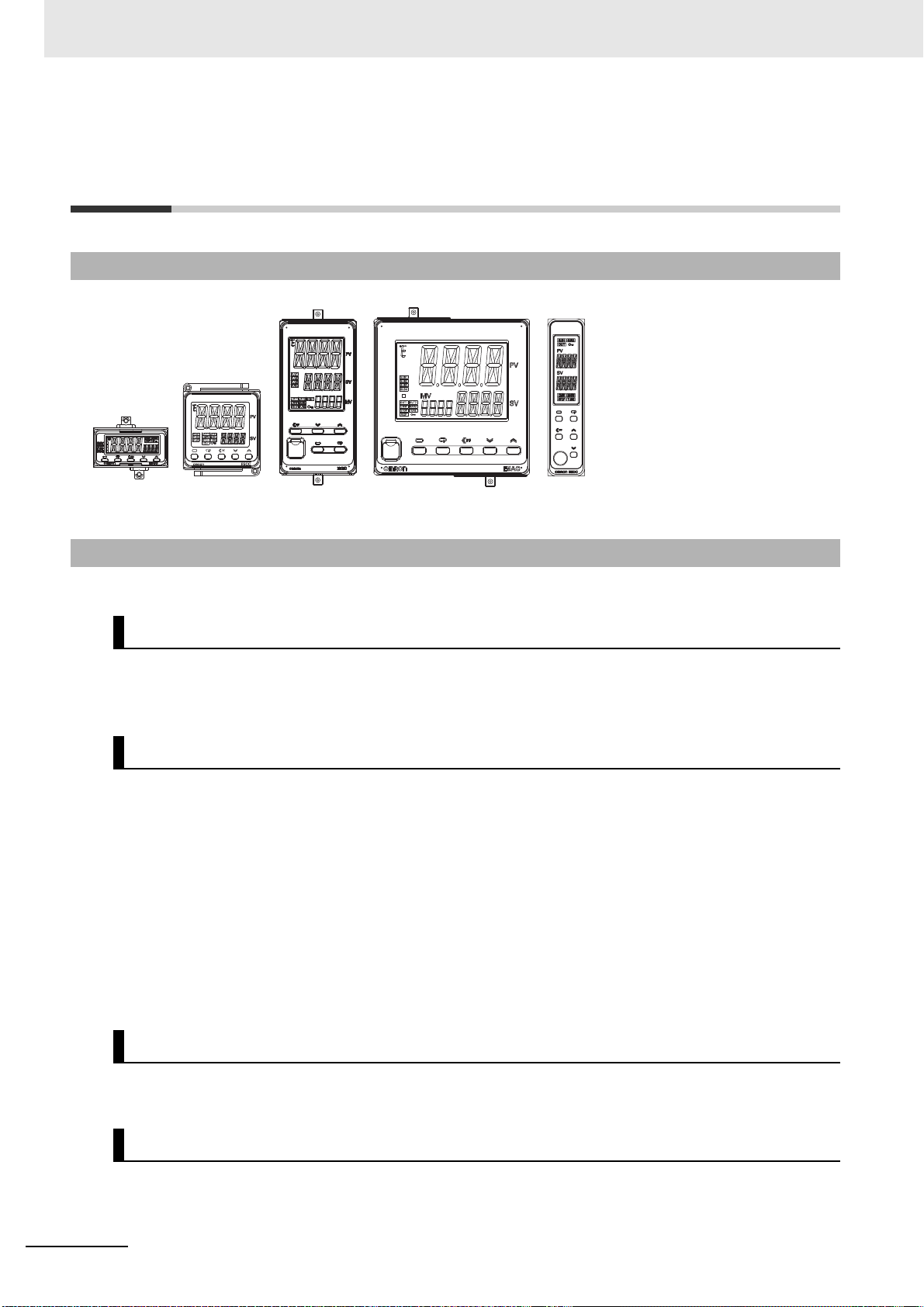
1 Introduction
E5CC, E5CC-U,
and E5CC-B
E5GC
E5EC and E5EC-B E5AC E5DC and
E5DC-B
1-1 Appearance, Features, and
Functions of the E5@C
1-1-1 Appearance
• A stylish design that gives a new
look to control panels.
• Large display characters and white
backlight for better visibility.
• A compact size to help downsize
control panels.
• Much faster sampling and greater
expandability than expected in this
class of Digital Controller.
• Even easier to use than previous
models.
1-1-2 Features
This section compares the features of the E5@C with the previous E5@N Digital Controllers.
High-speed Control Capability
Input sampling cycle: 50 ms
Control period: 0.1 s and 0.2 s have been added.
Integral/differential time unit: Setting in increments of 0.1 s has been added.
I/O Expandability
• Number of event inputs: Increased from 2 to 4 for the E5CC and from 4 to 6 for the E5EC/E5AC.
• Number of auxiliary outputs: Increased from 2 to 3 for the E5CC and from 3 to 4 for the E5EC/E5AC.
• Remote SP inputs: A remote SP input that treats the external analog signal at the set point
The E5DC has only 1 event input.
The E5GC or E5CC-B has 2 event inputs.
The E5EC-B has 6 event inputs.
* The E5DC-B does not support event inputs.
The E5DC, E5DC-B, E5CC-U, E5GC, or E5CC-B has 2 auxiliary
outputs.
The E5EC-B has 4 auxiliary outputs.
(SP) has been added.
1 - 2
Universal Input Capability
Universal input: The input sensor can be selected freely from the following: Thermocouple, resis-
tance thermometer, ES1B Infrared Temperature Sensor, current, and voltage.
Easier Numeric Inputs with a Digit Shift Key
Digit shift: When setting the SP or other parameters, you can use a Shift Key (assigned to the PF
Key) to shift the digit that is being set to aid changing the set values.
E5@C Digital Temperature Controllers User’s Manual (H174)
Page 27

Setup Tool Port on Front Panel of the E5EC, E5EC-B, E5AC, E5DC or
000
000
E5DC-B
This port allows you to change or set parameters from the Setup Tool even when the Digital Controller
is installed in a panel.
1-1-3 Main Functions
For details on particular functions and how to use them, refer to Section 3 Part Names and Basic Procedures and following sections.
Input Sensor Types
You can connect the following sensors and signals to the universal input.
Thermocouple (temperature input): K, J, T, E, L, U, N, R, S, B, W, PLII
Resistance thermometer (temperature input): Pt100, JPt100
Infrared Temperature Sensor (temperature input): ES1B
Current input (analog input): 4 to 20 mA DC, 0 to 20 mA DC
Voltage input (analog input): 1 to 5 VDC, 0 to 5 V DC, 0 to 10 V DC, 0 to 50 mVDC*
1 Introduction
1-1 Appearance, Features, and
Functions of the E5@C
1
1-1-3 Main Functions
10 to 70°C, 60 to 120°C, 115 to 165°C, 140 to 260°C
* This range can be used only for E5CC-U Digital
Controllers and only if they are manufactured in
May 2014 or later (version 2.2 or higher).
Control Outputs
• A control output can be a relay output, voltage output (for driving SSR), or linear current output,
depending on the model.
Adjusting PID Constants
• You can easily set the optimum PID constants by performing AT (auto-tuning) with the limit cycle
method or by performing ST (self-tuning) with the step response method.
• You can also add RT (robust tuning) to give priority to controlling stability.
Alarms
Standard Alarms
• You can output an alarm when the deviation, process value, set point, or manipulated value
reaches a specified value.
• You can also output alarms for the PV rate of change and for loop burnouts.
• If necessary, a more comprehensive alarm function can be achieved by setting a standby
sequence, alarm hysteresis, auxiliary output close in alarm/open in alarm, alarm latch, alarm ON
delay, and alarm OFF delay.
HB and HS Alarms
• With models with the optional HB and HS alarms, you can detect heater burnout and heater short
alarms based on CT inputs.
Integrated Alarm
• You can output an integrated alarm if a standard alarm, HB alarm, or HS alarm turns ON.
E5@C Digital Temperature Controllers User’s Manual (H174)
1 - 3
Page 28

1 Introduction
Event Inputs
• With any model that supports event inputs, you can use external contact or transistor inputs to
achieve any of the following functions: Switching set points (Multi-SP No. Switch, 8 points max.),
switching RUN/STOP, switching between automatic and manual operation, starting/resetting the
program, inverting direct/reverse operation, switching the SP mode100% AT execute/cancel, 40%
AT execute/cancel, setting change enable/disable, communications write enable/disable, and
canceling the alarm latch.
Communications Functions
With any E5@C model that supports communications, you can use CompoWay/F, Modbus-RTU,
programless, and component communications.
*1 Modbus is a registered trademark of Schneider Electric.
*2 The E5CC-U does not support communications.
Transfer Output
With any model that provides a transfer output, you can output the set point, process value,
manipulated variable, or other values as a 4 to 20-mA or 1 to 5-V transfer output. The E5CC-U*,
E5DC*, E5DC-B and E5GC do not have a transfer output, but if the control output is a linear current
output, the control output can be used as a simple transfer output.
* The E5CC-U must be manufactured in May 2014 or later (version 2.2 or higher) and the E5DC must be
manufactured in July 2014 or later (version 2.2 or higher).
*1
Remote SP Input
With any model that provides a remote SP input, you can set the set point with an analog input.
* The E5CC-U, E5DC, E5GC, E5CC-B, or E5DC-B does not have a remote SP input.
1 - 4
E5@C Digital Temperature Controllers User’s Manual (H174)
Page 29
1 Introduction
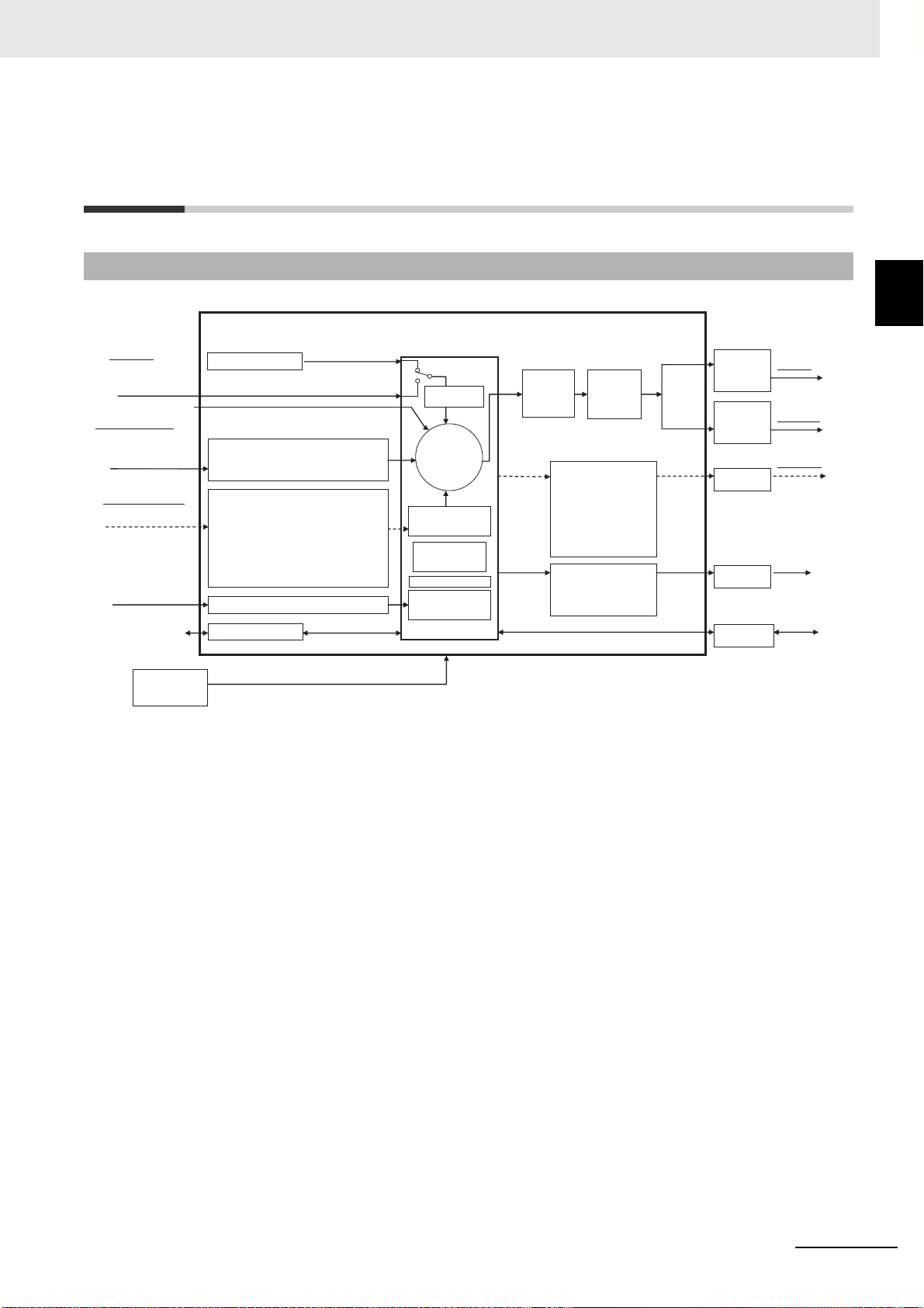
E5@C
Auxiliary outputs 1 to 4
• Input type • Input shift
• Input filter • Moving average
• Extraction of square root • Analog scaling
Input signals
Event inputs (EV1 to EV6)
• External inputs
(contact or non-contact input)
Setting and monitoring
• Direct/reverse
• Auto/manual
• Linear current
• Voltage output
(for driving SSR)
• Relay
Outputs
• RS-485
PV
•
Standard alarms (alarms 1 to 4)
• HB alarm
• HS alarm
• Input error (S.ERR)
•
RSP input error
•
Integrated alarm
•
RUN status
•
Program end
•
Work bits 1 to 8
Manipulated
value
(MV)
Setup Tool (CX-Thermo)
Limits
Output signals
A: 100 to 240 VAC
or
D: 24 VAC/DC
• CompoWay/F
• Modbus-RTU
Communications
• Linear current
• Linear voltage
Transfer output
CT input
Multi-SP
Input voltage from CT
Inputs
Set point (SP)
Local SP
Analog input (current/voltage)
Control
• HB alarm
• HS alarm
Alarms
Power supply
• Set point
• Set point during SP ramp
• Process value
• Manipulated value
• Relay
Analog status
Control output 1
Contact status
Operation
Process value (PV) input
• Thermocouple
• Resistance thermometer
• Infrared Temperature Sensor
• Analog input (current/voltage)
• Linear current
• Voltage output
(for driving SSR)
• Relay
Control output 2
• PID or
• ON/OFF control
Cooling
Close
*
*
*
Remote SP
SP mode
SP
• RUN/STOP switching •
Auto/manual selection
• Program start
•
100% AT execute/cancel
• 40% AT execute/cancel
• Alarm latch cancel • Multi-SP No.
• SP ramp
• Set point limiter
• Invert direct/reverse
operation
• SP mode
(remote/local
switching)
• Setting change
enable/disable
• Communications
write enable/disable
• Standard control or
• Heating/cooling
control
Automatic setting of
PID constants with AT
or ST
• MV limit
• MV
rate-ofchange limit
*
Functions can be assigned individually for each output by
changing the set values for the Control Output 1 and 2
Assignments and the Auxiliary Output 1 to 4 Assignments in the
parameters in the advanced function setting level.
Potentiometer input
Heating
Open
FB
1-2 I/O Configuration and Model
1-2 I/O Configuration and Model Number
Legend
1-2-1 I/O Configuration
Number Legend
1
1-2-1 I/O Configuration
Note: Not all models support these functions. For details, refer to 1-2-2 Model Number Legends.
E5@C Digital Temperature Controllers User’s Manual (H174)
1 - 5
Page 30
1 Introduction
--
-
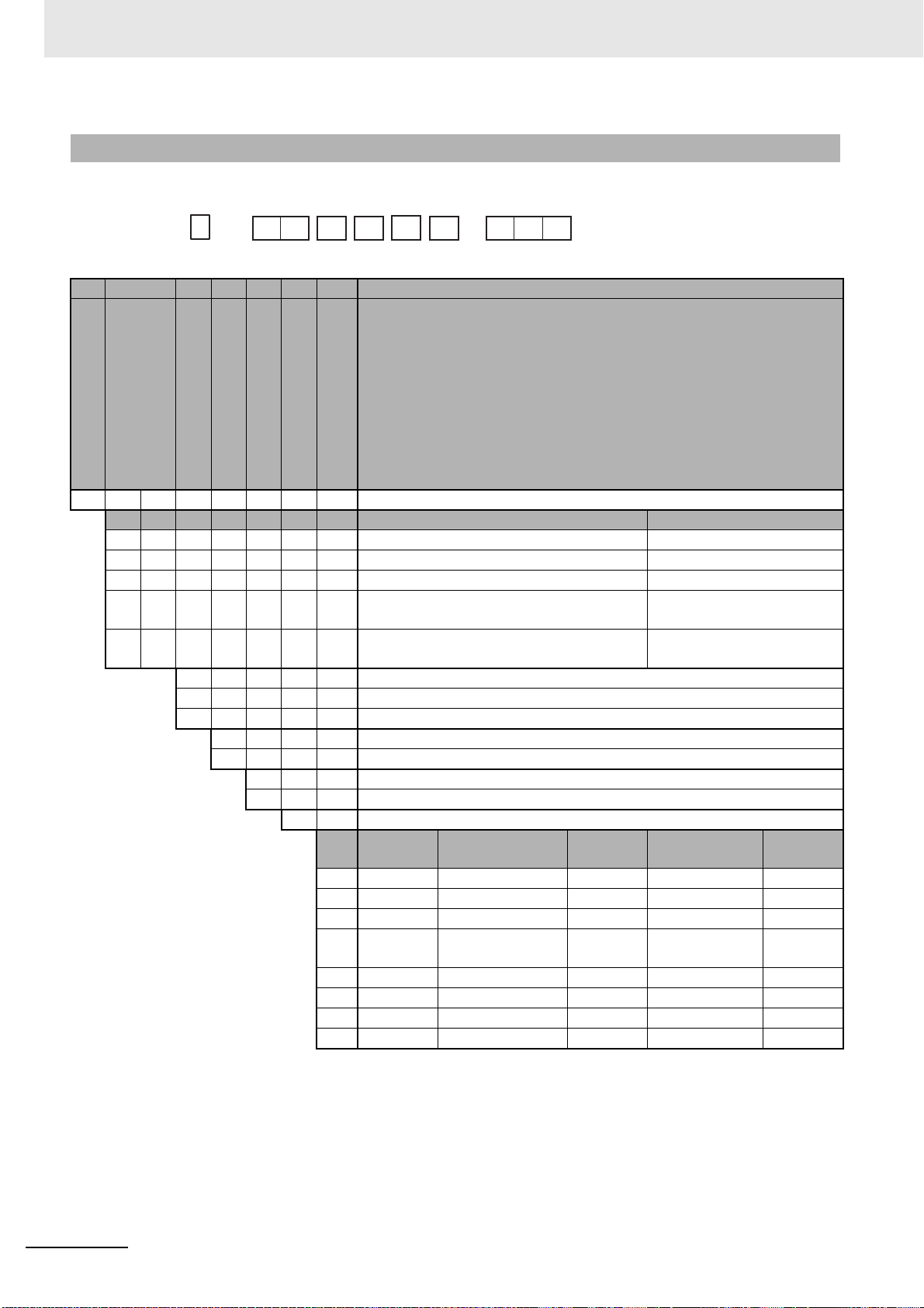
E5CC
-
-
(1) (2) (3) (4) (5) (6) (7)
Size
Control Outputs 1 and 2
No. of auxiliary outputs
Power supply voltage
Terminal type
Input type
Options
1-2-2 Model Number Legends
E5CC (Models with Screw Terminal Blocks)
(1) (2) (3) (4) (5) (6) (7) Meaning
C 48 × 48 mm
Control output 1 Control output 2
R X Relay output None
Q X Voltage output (for driving SSR) None
*1 C X Linear current output None
Q Q Voltage output (for driving SSR) Voltage output
(for driving SSR)
C Q Linear current output Voltage output
(for driving SSR)
*2*3 0 None
*3 2 2
33
A 100 to 240 VAC
D 24 VAC/DC
S Screw terminals
5 Screw terminals (with cover)
M Universal input
Event
inputs
000 --- --- --- --- --001 2 --- --- 1 ---
*3 002 --- RS-485 --- 1 ---
003 --- RS-485 --- 2 (for 3-phase
004 2 RS-485 --- --- --005 4 --- --- --- --006 2 --- --- --- Provided.
007 2 --- Provided. --- ---
Communications
Remote
SP Input
HB alarm and
HS alarm
heaters)
Transfer
output
---
*1 Options with HB and HS alarms (001, 002, and 003) cannot be selected if a linear current output is selected for the
control output.
The control output cannot be used as a simple transfer output.
*2 If no auxiliary outputs (none) is selected, 000 (none) must be selected for the options.
*3 These cannot be selected if 5 (screw terminals with cover) is selected for the terminal type.
1 - 6
E5@C Digital Temperature Controllers User’s Manual (H174)
Page 31

E5CC-U (Plug-in Models)
-
-
Size
Control output 1
No. of auxiliary outputs
Power supply voltage
Terminal type
Input type
Options
-
E5CC
-
U
(1) (2) (3) (4) (5) (6) (7)
(1) (2) (3) (4) (5) (6) (7) Meaning
C48 × 48 mm
R W Relay output (SPDT contacts)
Q X Voltage output (for driving SSR)
*1 C X Linear current output
0
11
22
A 100 to 240 VAC
D24 VAC/DC
U Plug-in model
M Universal input
000
None
Event
inputs
--- --- --- --- ---
Communications
-
Control output 1
Remote
SP Input
HB alarm and HS
1 Introduction
alarm
1-2 I/O Configuration and Model
Number Legend
1
1-2-2 Model Number Legends
Transfer
output
*1 The control output can be used as a simple transfer output for Digital Controllers manufactured in May 2014 or later
(version 2.2 or higher).
E5@C Digital Temperature Controllers User’s Manual (H174)
1 - 7
Page 32

1 Introduction
--
-
E5CC B
-
-
(1)
(2) (3) (4) (5) (6) (7)
Size
Control output 1
No. of auxiliary outputs
Power supply voltage
Terminal type
Input type
Options
E5CC-B (Models with Push-In Plus Terminal Blocks)
(1) (2) (3) (4) (5) (6) (7) Meaning
C48 × 48 mm
Control output 1 Control output 2
R X Relay output None
Q X Voltage output (for driving SSR) None
*1 C X Linear current output None
2 2 (one common)
A 100 to 240 VAC
D 24 VAC/DC
B Push-In Plus terminal blocks
M Universal input
Event
inputs
000 --- --- --- --- --001 2 --- --- 1 --002 --- RS-485 --- 1 --004 2 RS-485 --- --- --006 2 --- --- --- Provided.
Communi
cations
Remote
SP input
HB alarm and HS
alarm
Transfer
output
*1 Options with 001 and 002 cannot be selected if a linear current output is selected for the control output.
The control output cannot be used as a simple transfer output.
1 - 8
E5@C Digital Temperature Controllers User’s Manual (H174)
Page 33

1 Introduction
-- -
E5 C
- -
(1) (2) (3) (4) (5) (6) (7)
Size
Control Outputs 1 and 2
No. of auxiliary outputs
Power supply voltage
Terminal type
Input type
Options
E5EC/AC (Models with Screw Terminal Blocks)
(1) (2) (3) (4) (5) (6) (7) Meaning
E48 × 96 mm
A96 × 96 mm
Control output 1 Control output 2
*1 R X Relay output None
*1 Q X Voltage output (for driving SSR) None
*2*1 C X Linear current output None
*1 Q Q Voltage output (for driving SSR) Voltage output (for driving SSR)
*1 Q R Voltage output (for driving SSR) Relay output
*1 R R Relay output Relay output
*2*1 C C Linear current output Linear current output
*2*1 C Q Linear current output Voltage output (for driving SSR)
*1 P R Position-proportional relay output Position-proportional relay output
*3 2 2
44
A 100 to 240 VAC
D 24 VAC/DC
S Screw terminals
5 Screw terminals (with cover)
M Universal input
Event
inputs
000 --- --- --- --- --- Selectable Selectable Selectable
004 2 RS-485 --- --- --- --- Selectable Selectable
005 4 --- --- --- --- --- Selectable ---
*3 008 2 RS-485 --- 1 --- Selectable --- ---
009 2 RS-485 --- 2 (for
010 4 --- --- 1 --- Selectable --- ---
011 6 --- Provided. 1 Provided. Selectable --- ---
*3 012 4 RS-485 Provided. 1 Provided. Selectable --- ---
013 6 --- Provided. --- Provided. --- Selectable ---
014 4 RS-485 Provided. --- Provided. --- Selectable Selectable
Communications
Remote
SP Input
HB alarm
and HS
alarm
3-phase
heaters)
Transfer
output
--- Selectable --- ---
For RX,
QX, RR,
QQ, QR,
or CQ
For CX or
CC
For PR
1-2 I/O Configuration and Model
Number Legend
1
1-2-2 Model Number Legends
*1 The options that can be selected depend on the type of control output.
*2 The control output cannot be used as a simple transfer output.
*3 These cannot be selected if 5 (screw terminals with cover) is selected for the terminal type.
E5@C Digital Temperature Controllers User’s Manual (H174)
1 - 9
Page 34

1 Introduction
-- -
E5EC
- -
(1) (2) (3) (4) (5) (6) (7)
B
Size
Control Outputs 1 and 2
No. of auxiliary outputs
Power supply voltage
Terminal type
Input type
Options
E5EC-B (Models with Push-In Plus Terminal Blocks)
(1) (2) (3) (4) (5) (6) (7) Meaning
E
*1 R X Relay output None
*1 Q X Voltage output (for driving SSR) None
*2 C X Linear current output None
22
44
A 100 to 240 VAC
D 24 VAC/DC
B Push-In Plus terminal blocks
M Universal input
48 × 96 mm
Control output 1 Control output 2
Event inputs
000 --- --- --- --- ---
004 2 RS-485 --- --- ---
008 2 RS-485 --- 1 ---
010 4 --- --- 1 ---
011 6 --- Provided. 1 Provided.
014 4 RS-485 Provided. --- Provided.
Communicat
ions
Remote SP
input
HB alarm
and HS
alarm
Transfer
output
*1 Options with 004 and 014 cannot be selected if a relay output or voltage output (for driving SSR) is selected for the
control output.
*2 Options with 008, 010 and 011 cannot be selected if a linear current output is selected for the control output.
The control output cannot be used as a simple transfer output.
1 - 10
E5@C Digital Temperature Controllers User’s Manual (H174)
Page 35

E5DC
E5DC
−
(1) (2) (3) (4) (5) (6) (7)
−
Size
Control Output 1
No. of auxiliary outputs
Power supply voltage
Terminal type
Input type
Options
(1) (2) (3) (4) (5) (6) (7) Meaning
D 22.5 mm wide and mounts to DIN Track
Control output 1
*1 R X Relay output
*1 Q X Voltage output (for driving SSR)
*1*2 C X Linear current output
*1 0 None
*1 2 2
A 100 to 240 VAC
D 24 VAC/DC
S Terminal screw block (Main Unit and Terminal Unit together)
U Main Unit only (no Terminal Unit)
M Universal input
Event inputs Communications HB alarm and HS alarm
000 --- --- ---
002 --- RS-485 1
015 --- RS-485 ---
016 1 --- ---
017 1 --- 1
1 Introduction
1-2 I/O Configuration and Model
Number Legend
1
1-2-2 Model Number Legends
*1 The options that can be selected depend on the type of control output and number of auxiliary outputs.
Control output
RX or QX 0 --- --- Selectable --- ---
CX 0 --- --- Selectable --- ---
No. of auxiliary
outputs
2 Selectable Selectable --- --- Selectable
2 Selectable --- Selectable Selectable ---
000 002 015 016 017
Options
*2 The control output can be used as a simple transfer output for Digital Controllers manufactured in July 2014 or later
(version 2.2 or higher).
E5@C Digital Temperature Controllers User’s Manual (H174)
1 - 11
Page 36

1 Introduction
E5DC
B
(1) (2) (3) (4) (5) (6) (7)
−−
Size
Control Output 1
No. of auxiliary outputs
Power supply voltage
Terminal type
Input type
Options
E5DC-B (Models with Push-In Plus Terminal Blocks)
(1) (2) (3) (4) (5) (6) (7) Meaning
D 22.5 mm wide and mounts to DIN Track
*1 R X Relay output
*1 Q X Voltage output (for driving SSR)
*1*2 C X Linear current output
*1 0 None
*1 2 2
A 100 to 240 VAC
D 24 VAC/DC
B Push-In Plus terminal blocks
M Universal input
Event inputs Communications HB alarm and HS alarm
000 --- --- ---
002 --- RS-485 1
015 --- RS-485 ---
Control output 1
*1 The options that can be selected depend on the type of control output and number of auxiliary outputs.
Control output
RX or QX 0 --- --- Selectable
CX 0 --- --- Selectable
No. of auxiliary
outputs
2 Selectable Selectable ---
2 Selectable --- Selectable
000 002 015
Options
*2 The control output can be used as a simple transfer output.
1 - 12
E5@C Digital Temperature Controllers User’s Manual (H174)
Page 37

E5GC
E5GC
−
(1) (2) (3) (4) (5) (6) (7)
−
Size
Control Output 1
No. of auxiliary outputs
Power supply voltage
Terminal type
Input type
Options
(1) (2) (3) (4) (5) (6) (7) Meaning
G 48 × 24 mm
Control output 1
R X Relay output
Q X Voltage output (for driving SSR)
*1 C X Linear current output
*2 0 None
11
22
A 100 to 240 VAC
D 24 VAC/DC
6 Screw terminals (with cover)
C Screwless clamp terminals
M Universal input
Event inputs Communications
000 --- --- ---
015 --- RS-485 ---
*3 016 1 --- ---
*3*4 023 --- --- 1
*5 024 2 --- ---
1 Introduction
1-2 I/O Configuration and Model
Number Legend
1
1-2-2 Model Number Legends
Single-phase HB alarm
and HS alarm
*1 The control output can be used as a simple transfer output.
*2 If no auxiliary outputs (none) is selected, 000 (none) must be selected for the options.
*3 These options can be selected only if two auxiliary outputs are selected.
*4 The option for HB and HS alarms (023) cannot be selected if a linear current output is selected for the control output.
*5 This option can be selected only if one auxiliary output is selected.
E5@C Digital Temperature Controllers User’s Manual (H174)
1 - 13
Page 38

1 Introduction
1 - 14
E5@C Digital Temperature Controllers User’s Manual (H174)
Page 39

Preparations
2-1 Installation . . . . . . . . . . . . . . . . . . . . . . . . . . . . . . . . . . . . . . . . . . . . . . . . . . . 2-2
2-1-1 Dimensions (Unit: mm) . . . . . . . . . . . . . . . . . . . . . . . . . . . . . . . . . . . . . . . . . . . 2-2
2-1-2 Panel Cutout (Unit: mm) . . . . . . . . . . . . . . . . . . . . . . . . . . . . . . . . . . . . . . . . . . 2-6
2-1-3 Mounting . . . . . . . . . . . . . . . . . . . . . . . . . . . . . . . . . . . . . . . . . . . . . . . . . . . . . . 2-9
2-2 Using the Terminals . . . . . . . . . . . . . . . . . . . . . . . . . . . . . . . . . . . . . . . . . . . 2-24
2-2-1 E5CC Terminal Block Wiring Example . . . . . . . . . . . . . . . . . . . . . . . . . . . . . . 2-24
2-2-2 E5CC-U Terminal Block Wiring Example . . . . . . . . . . . . . . . . . . . . . . . . . . . . 2-29
2-2-3 E5CC-B Terminal Block Wiring Example . . . . . . . . . . . . . . . . . . . . . . . . . . . . 2-32
2-2-4 E5EC/E5AC Terminal Block Wiring Example . . . . . . . . . . . . . . . . . . . . . . . . . 2-36
2-2-5 E5EC-B Terminal Block Wiring Example . . . . . . . . . . . . . . . . . . . . . . . . . . . . 2-41
2-2-6 E5DC Terminal Block Wiring Example . . . . . . . . . . . . . . . . . . . . . . . . . . . . . . 2-46
2-2-7 E5DC-B Terminal Block Wiring Example . . . . . . . . . . . . . . . . . . . . . . . . . . . . 2-49
2-2-8 E5GC Terminal Block Wiring Example . . . . . . . . . . . . . . . . . . . . . . . . . . . . . . 2-52
2-2-9 Precautions when Wiring . . . . . . . . . . . . . . . . . . . . . . . . . . . . . . . . . . . . . . . . 2-55
2-2-10 Wiring . . . . . . . . . . . . . . . . . . . . . . . . . . . . . . . . . . . . . . . . . . . . . . . . . . . . . . . 2-61
2-3 Insulation Block Diagrams . . . . . . . . . . . . . . . . . . . . . . . . . . . . . . . . . . . . . 2-73
2
2-4 Using the Setup Tool Port . . . . . . . . . . . . . . . . . . . . . . . . . . . . . . . . . . . . . . 2-76
2-4-1 Procedure . . . . . . . . . . . . . . . . . . . . . . . . . . . . . . . . . . . . . . . . . . . . . . . . . . . . 2-76
2-4-2 Connection Method . . . . . . . . . . . . . . . . . . . . . . . . . . . . . . . . . . . . . . . . . . . . . 2-76
2-4-3 Installing the Driver . . . . . . . . . . . . . . . . . . . . . . . . . . . . . . . . . . . . . . . . . . . . . 2-83
E5@C Digital Temperature Controllers User’s Manual (H174)
2 - 1
Page 40

2 Preparations
48 × 48
44.8 × 44.8
(64)
58
604
1
48 × 48
44.8 × 44.8
58
76.8
58.64 14.2
(71.4)
67.4
4
(1)
58
48 × 48
44.8 × 44.8
2-1 Installation
2-1-1 Dimensions (Unit: mm)
E5CC
E5CC-U
E5CC-B
2 - 2
E5@C Digital Temperature Controllers User’s Manual (H174)
Page 41

E5EC
44
91
48
96
1
60
4
(64)
110
110
67.4
(71.4)
4
(1)
96
48
44
91
2 Preparations
2-1 Installation
2
2-1-1 Dimensions (Unit: mm)
E5EC-B
E5@C Digital Temperature Controllers User’s Manual (H174)
2 - 3
Page 42

2 Preparations
96
22.5
110
354
(85)
81
4
22.5
Adapter (sold separately)
Main Unit Terminal Unit
+1.15
-0.2
90
+1.15
-0.2
90
E5AC
96 × 96
(64)
60
4
1
91 × 91
110
E5DC
The following figure shows the Terminal Unit attached to the Main Unit.
2 - 4
E5@C Digital Temperature Controllers User’s Manual (H174)
Page 43

E5DC-B
486
(90)
110
(6.5)
96
22.5 (6.5)22.5
+1.15
-0.2
90
+1.15
-0.2
4
35
90
Adapter (sold separately)
Main Unit Push-in Plus
Terminal Unit
24
48
63.6 4
1
1
90
22
40.8
44.8
22
24
48
63.6 4 93
22
40.8
44.8
22
Models with Screwless Clamp Terminal Blocks
Models with Screw Terminal Blocks
The figure below shows the Push-in Plus Terminal Unit attached to the Main Unit.
2 Preparations
2-1 Installation
2
2-1-1 Dimensions (Unit: mm)
E5GC
E5@C Digital Temperature Controllers User’s Manual (H174)
2 - 5
Page 44

2 Preparations
60 min.
+1.0
0
Individual Mounting
Group Mounting
(48 × number of Units − 2.5)
45
+0.6
0
45
+0.6
0
45
+0.6
0
Individual Mounting
120 min.
+1.0
0
Group Mounting
*1
(48 × number of Units − 2.5)
45
+0.6
0
92
+0.8
0
92
+0.8
0
Individual Mounting
120 min.
+1.0
0
Group Mounting
(96 × number of Units − 3.5)
92
+0.8
0
92
+0.8
0
92
+0.8
0
2-1-2 Panel Cutout (Unit: mm)
E5CC/E5CC-U/E5CC-B
E5EC/E5EC-B
E5AC
2 - 6
E5@C Digital Temperature Controllers User’s Manual (H174)
Page 45

E5DC/E5DC-B
120 min.
Individual Mounting
Two-Unit Mounting Group Mounting
22.7
+0.3
0
45
+0.6
0
92
+0.8
0
92
+0.8
0
92
+0.8
0
(22.5 x number of Units)
+1.0
0
Individual Mounting Horizontal Group
Mounting
*2
Vertical Group Mounting
*2
22.2
+0.3
+0
40 min.
22.2
+0.3
+0
45
+0.6
+0
L1
45
+0.6
+0
L2
+1.0
+0
L1=(48×n-2.5)
+1.0
+0
L2=(24×n-1.5)
n: Number of mounted Controllers (2 ≤ n ≤ 6)
E5EC-@@ @ @ @ M-@@@
QQ, QR,
RR, CC, CQ, PR
011, 012,
013, 014
E5GC
2 Preparations
2-1 Installation
2
2-1-2 Panel Cutout (Unit: mm)
• The E5CC-U, E5DC, and E5DC-B cannot be waterproofed.
• Waterproofing is not possible when group mounting several Digital Controllers.
• The recommended panel thickness is 1 to 5 mm for the E5CC, E5CC-U, and E5CC-B, and 1 to 8 mm
for E5EC, E5EC-B, E5AC, E5DC, E5DC-B, and E5GC.
• Except for the E5GC with a screwless clamp terminal block, Digital Controllers must not be group
mounting vertically. (Observe the recommended mounting space limits.)
• When two or more Digital Controllers are mounted, make sure that the ambient temperature of the
Digital Controllers does not exceed the allowable operating temperature specified in the
specifications.
*1 For E5EC models with two control outputs (QQ, QR, CQ, RR, CC, or PR) and 011, 012, 013, or 014 options
(shown below), the ambient temperature for group mounting must be 45°C max.
E5@C Digital Temperature Controllers User’s Manual (H174)
2 - 7
Page 46

2 Preparations
45
+0.6
0
92
120 min.
+0.8
0
60 min.
To mount these models at an ambient temperature of 55°C, install them at the following intervals.
*2 When two or more E5GC Digital Controllers are mounted, make sure that the ambient temperature of the
Controller does not exceed the allowable operating temperature range given below.
Horizontal group mounting: −10 to 55°C
Vertical group mounting of two Digital Controllers: −10 to 45°C
Vertical group mounting of three or more Digital Controllers: −10 to 40°C
Note: Use Digital Controllers with screwless clamp terminal blocks for vertical group mounting. If you use
vertical group mounting, you cannot draw out the interior body of the Digital Controllers.
2 - 8
E5@C Digital Temperature Controllers User’s Manual (H174)
Page 47

2-1-3 Mounting
Adapter
Waterproof packing
Panel
E53-COV17
Terminal Cover
(Sold separately.)
Adapter
E53-COV23
Terminal Cover*
* The Terminal Cover is provided only with
the following models:
E5CC-@@@@5M-@@@.
E5CC, E5CC-B, and E5CC-U
There are two models of Terminal Covers that you can use with the E5CC.
2 Preparations
2-1 Installation
2
2-1-3 Mounting
For the Wiring Socket for the E5CC-U, purchase the P2CF-11 or PG3A-11 separately.
Mounting to the Panel
(1) For waterproof mounting, waterproof packing must be installed on the Digital Controller.
Waterproofing is not possible when group mounting several Digital Controllers. The
E5CC-U cannot be waterproofed even if the Waterproof Packing is inserted.
(2) Insert the E5CC, E5CC-B, or E5CC-U into the mounting hole in the panel.
E5@C Digital Temperature Controllers User’s Manual (H174)
(3) Push the Adapter from the terminals up to the panel, and temporarily fasten the E5CC,
E5CC-B, or E5CC-U.
(4) Tighten the two fastening screws on the Adapter. Alternately tighten the two screws little by
little to maintain a balance. Tighten the screws to a torque of 0.29 to 0.39 N·m.
2 - 9
Page 48

2 Preparations
Terminal Cover
(E53-COV17)
(Sold separately.)
Adapter
• E53-COV17 • E53-COV23
Enlarged Illustration of
Terminal Section
Mounting the Terminal Cover (E5CC Only)
Slightly bend the E53-COV23 Terminal Cover to attach it to the terminal block as shown in the following
diagram. The Terminal Cover cannot be attached in the opposite direction. Or, you can use the E53-COV17
Terminal Cover. Make sure that the “UP” mark is facing up, and then attach the E53-COV17 Terminal Cover to
the holes on the top and bottom of the Digital Controller.
2 - 10
E5@C Digital Temperature Controllers User’s Manual (H174)
Page 49

E5EC, E5EC-B, or E5AC
Adapter
Waterproof packing
Panel
E53-COV24
Terminal Cover
Adapter
E53-COV24
Terminal Cover*
* The Terminal Cover is provided only with the
following models: E5EC-@@@@5M-@@@.
Slightly bend the
E53-COV24 Terminal
Cover in the direction
shown by the arrows
to attach it to the
terminal block.
Enlarged Illustration of Terminal Section
2 Preparations
2-1 Installation
2
2-1-3 Mounting
Mounting to the Panel
(1) For waterproof mounting, waterproof packing must be installed on the Digital Controller.
Waterproofing is not possible when group mounting several Digital Controllers.
(2) Insert the E5EC, E5EC-B, or E5AC into the mounting hole in the panel.
(3) Push the Adapter from the terminals up to the panel, and temporarily fasten the E5EC,
E5EC-B, or E5AC.
(4) Tighten the two fastening screws on the Adapter. Alternately tighten the two screws little by
little to maintain a balance. Tighten the screws to a torque of 0.29 to 0.39 N·m.
Mounting the Terminal Cover (E5EC or E5AC Only)
Slightly bend the E53-COV24 Terminal Cover to attach it to the terminal block as shown in the following
diagram. The Terminal Cover cannot be attached in the opposite direction.
E5@C Digital Temperature Controllers User’s Manual (H174)
2 - 11
Page 50

2 Preparations
Panel
Adapter
Terminal Unit
Main Unit
1
2
3
Common Procedure of E5DC and E5DC-B
Mounting to the Panel
1
Insert the E5DC or E5DC-B into the mounting hole in the panel. (Attach the Terminal Unit
after you insert the Main Unit.)
2
Push the Adapter from the Terminal Unit up to the panel, and temporarily fasten the
E5DC or E5DC-B.
3
Tighten the two fastening screws on the Adapter. Alternately tighten the two screws
little by little to maintain a balance.
Tighten the screws to a torque of 0.29 to 0.39 N·m.
E5DC
Mounting to and Removing from DIN Track
• Mounting a Unit
Pull down the DIN Track hook on the Terminal Unit and catch the top hook on the DIN Track.
Press the Unit onto the DIN Track until the DIN Track hooks are locked in place.
2. Catch the top hook on
the DIN Track.
3. Press the Unit onto
the DIN Track.
1. Pull down the hook.
• Removing a Unit
Pull down on the DIN Track Hook with a flat-blade screwdriver and lift up the Unit.
4. Make sure that the hooks
are locked in place.
2 - 12
E5@C Digital Temperature Controllers User’s Manual (H174)
Page 51

Removing the Main Unit
(1)
(1) Push in the hooks.
(2) Pull out the Main Unit.
Individual Mounting Group Mounting
(1)
(2)
(1) Pull down the hook.
(2) Catch the top hook
on the DIN Track.
(3) Press the Unit
onto the DIN
Track.
(4) Make sure that the
hooks are locked
in place.
Press in the two hooks on the Main Unit and remove the Main Unit from the Terminal Unit.
End Plate Installation
Make sure to attach PFP-M End Plates to the ends of the Units.
• End Plate (sold separately)
PFP-M
2 Preparations
2-1 Installation
2
2-1-3 Mounting
E5DC-B
Mounting to and Removing from DIN Track
• Mounting a Unit
Mount the Main Unit after first mounting the Terminal Unit on the DIN Track.
E5@C Digital Temperature Controllers User’s Manual (H174)
2 - 13
Page 52

2 Preparations
• Removing a Unit
Pull down on the DIN Track Hook with a flat-blade screwdriver and lift up the Unit.
Removing the Main Unit
(1)
(2) Pull out the Main Unit.
(1) Push in the hooks.
End Plate Installation
Make sure to attach PFP-M End Plates to the ends of the Units.
Individual Mounting Group Mounting
Mounting the DIN Track
Refer to Mounting the DIN Track on page 2-13.
(2)
(1)
2 - 14
E5@C Digital Temperature Controllers User’s Manual (H174)
Page 53

2 Preparations
Precautions for Correct Use
Linking connector
(female side)
Linking connector
(male side)
Vertical: OK Horizontal: NG
Linked Mounting/Removal of the E5DC-B
A built-in connector for linking is provided in the E5DC-B that enables linked mounting of units together
with DIN Track and panel mounting. As a result, crossover wiring is not required for communication and
power supply. Up to 16 units can be linked.
2-1 Installation
2
2-1-3 Mounting
• Wiring
When linking the units together, connect the power cable only to the unit at the left end of the
linkage block. Incorrect wiring can be shorted inside the unit resulting in damage to the unit.
Do not perform crossover wiring between each linkage block, or to another device. This could
result in a breakdown or incorrect operation.
Prohibited Multiplex
Power Input Wiring
Incorrect Incorrect
Prohibited Crossover Wiring
Mounting the DIN Track
Attach the DIN Track to the inside of the control panel with screws to at least three locations.
• DIN Track (sold separately)/PFP-50N (50 cm) and PFP-100N (100 cm)
Install the DIN Track vertically to the ground.
E5@C Digital Temperature Controllers User’s Manual (H174)
2 - 15
Page 54

2 Preparations
Precautions for Correct Use
Connector cover
(Provided)
Left side:
End Plate
2
1
4
3
Linked Mounting on DIN Track
1
Remove the connector cover
of the Terminal Unit from the
side that is to be linked, and
mount the Unit on the DIN
Track.
2
Link the connectors of the
Terminal Units.
3
Wire the Terminal Units.
4
Insert the Main Unit into the
Terminal Unit.
• When N units are linked together, the inrush current will be equal to N times that for 1 unit. Be
sure to use the external fuse with the appropriate fusing characteristics, and the breaker with
the appropriate tripping characteristics to ensure that the fuse does not melt and the breaker is
not activated due to the inrush current. The inrush current per Unit is 30 A or less.
• Do not remove the connector cover from connectors that are not to be linked. The connector
covers have been mounted on the product during shipment.
• Do not add or separate the units during power-on.
2 - 16
E5@C Digital Temperature Controllers User’s Manual (H174)
Page 55

Removing from the DIN Track
Additional Information
1
2
1
Remove the Main Unit from
the Terminal Unit.
2 Preparations
2
Remove the Terminal Units.
3
Remove the Terminal Units
from the DIN Track.
2-1 Installation
2
2-1-3 Mounting
3
Removing the Terminal Unit Using a Flat-blade Screwdriver
• There are two slits on the right side of the Terminal Unit. When Terminal Units are linked, these
slits act as gaps for inserting a flat-blade screwdriver. The Terminal Units can be easily
removed by inserting a flat-blade screwdriver in these gaps. Perform this operation after
removing the Main Unit.
Gaps for inserting
the flat-blade screwdriver
Slits
• For Recommended Flat-blade Screwdriver, refer to Recommended Flat-blade Screwdriver on
page 2-61.
E5@C Digital Temperature Controllers User’s Manual (H174)
2 - 17
Page 56

2 Preparations
4
5
Linked Mounting on the Mounting Panel
1
Push the Main Unit into the
mounting holes on the
mounting panel.
2
Mount a wired Terminal Unit
on the Main Unit.
3
Push the Adapter from the
Terminal Unit side up to the
Mounting Panel, and
temporarily fasten the Main
Unit. Tighten the two
fastening screws on the
Adapter. Alternately tighten
the two screws little by little
to maintain a balance.
Tighten the screws to a
torque of 0.29 to 0.39 N·m.
3
Adapter
2
Panel
1
Adapter
3
4
Remove the connector cover
of the wired Terminal Unit
from the side that is to be
linked, and link the
connectors.
5
Push the Main Unit into the
mounting holes on the
mounting panel, and attach it
to the Terminal Unit.
2 - 18
E5@C Digital Temperature Controllers User’s Manual (H174)
Page 57

Precautions for Correct Use
6
Push the Adapter from the
Terminal Unit up to the panel,
and temporarily fasten the
E5DC. Tighten the two
fastening screws on the
Adapter. Alternately tighten
the two screws little by little
to maintain a balance.
Tighten the screws to a
torque of 0.29 to 0.39 N·m.
2 Preparations
6
Adapter
2-1 Installation
2
Adapter
6
• Do not remove the connector cover from connectors that are not to be linked. The connector
covers have been mounted on the product during shipment.
• Do not add or separate the units during power-on.
Removing from the Mounting Panel
1
Remove the Adapter
attached to the Main Unit.
Adapter
1
2-1-3 Mounting
E5@C Digital Temperature Controllers User’s Manual (H174)
Adapter
1
2 - 19
Page 58

2 Preparations
2
Remove the Main Unit from
the Terminal Unit.
3
Remove the Terminal Units.
2
3
2 - 20
E5@C Digital Temperature Controllers User’s Manual (H174)
Page 59

E5GC
Waterproof packing
Panel
Terminal block
Adapter
(1)
(1)
(2)
Rear case
Front panel
Draw-out Jig insertion holes
Draw-out Jig
Mounting to the Panel
(1) When waterproofing is required, insert the Waterproof Packing on the backside of the front
panel. Digital Controllers cannot be waterproofed when they are mounted side by side.
(2) Insert the E5GC into the mounting hole in the panel.
(3) Use two Adapters, either on the top and bottom or on the right and left.
2 Preparations
2-1 Installation
2
2-1-3 Mounting
(4) Push the Adapter from the terminals up to the panel, and temporarily fasten the Digital
Controller.
(5) Tighten the two fastening screws on each Adapter. Alternately tighten the two screws little
by little to maintain a balance. Tighten the screws to a torque of 0.29 to 0.39 N·m.
Drawing Out the Interior Body of the E5GC to Replace It
You can use the Y92F-55 Draw-out Jig to remove the interior body of the Digital Controller from the case to
perform maintenance without removing the terminal leads. This is possible for only the E5GC. Check the
specifications of the case and Digital Controller before removing the interior body from the case.
1. Drawing Out the Interior Body from the Rear Case
(1) Slowly insert the Draw-out Jig into the Draw-out Jig insertion holes laterally until it clicks
into place. (There is a hole at both the top and bottom.) (If you attempt to draw out the
interior body of the Digital Controller when only one hook is engaged, the Digital Controller
may be damaged.)
Draw-out Jig insertion holes
Hook
(2) Pull out the Draw-out Jig together with the front panel. Do not pull with excessive force.
Slowly pull out the Digital Controller laterally. (If you pull the interior body out at an angle,
the Digital Controller may be damaged.)
E5@C Digital Temperature Controllers User’s Manual (H174)
(3) After the interior body is free from the rear case, support the interior body with one hand
and draw it out slowly in a horizontal direction.
2 - 21
Page 60

2 Preparations
Top View
Sealing rubber position
Rear case hooks
PCB
Rear case hooks
(1)
(2)
(2)
Case hooks
* Make sure that the top and bottom PCBs are parallel to each
other, and then press the interior body toward the rear case.
(2)
(1)
(3)
2. Inserting the Interior Body into the Rear Case
(1) When inserting the interior body back into the rear case, make sure the PCBs are parallel to
(2) When you press the Digital Controller into position, press down on the rear case hooks so
each other, mount the sealing rubber, and press the interior body toward the rear case and
into position, making sure that the sealing rubber does not move.
that the case hooks securely lock in place. (There are rear case hooks at both the top and
bottom of the rear case.) If the Digital Controller is not correctly mounted into the rear case,
the rear case may not be waterproof. When inserting the Digital Controller, do not allow the
electronic components to touch the rear case.
Removing the Draw-out Jig when only one hook is caught in the Draw-out Jig
insertion hole
(1) Pull the Draw-out Jig slowly in the direction shown in the figure. (This step is the same even
(2) Confirm that the Draw-out Jig is free of the Draw-out Jig insertion hole.
(3) If the interior body separates from the rear case, slowly press the interior body into the rear
If you do not follow the procedures above, the Digital Controller may be damaged.
2 - 22
if the other hook is caught.)
case in a horizontal direction.
E5@C Digital Temperature Controllers User’s Manual (H174)
Page 61

2 Preparations
2.00.4
Insert a tool.
20 min.
Flat-blade screwdriver
(unit: mm)
Removing the Terminal Block
The terminal block can be removed from the E5GC. Doing so is not possible with the E5CC, E5CC-U, E5CC-B,
E5EC, E5EC-B, or E5AC.
(1) Insert a flat-blade screwdriver into the tool holes (one on the top and one on the bottom) to
release the hooks. Do not apply excessive force.
(2) Pull the terminal block out while the hooks are released.
Note: The method for removing the terminal block is the same for both screw terminal blocks and screwless clamp
terminal blocks.
Do not connect the wrong type of terminal block to the Digital Controller. For example, do not connect a
screwless clamp terminal block to a
affected.
Digital Controller for a screw terminal block. Performance may be
2-1 Installation
2
2-1-3 Mounting
E5@C Digital Temperature Controllers User’s Manual (H174)
2 - 23
Page 62

2 Preparations
Precautions for Correct Use
G
H
I
J
K
L
M
O
P
Q
R
A
B
C
D
E
F
Control outputs 1 and 2
Sensor input
Auxiliary outputs
Input power supply
Options
14
E5CC-@@ @ @ @ M-@@@
Control outputs 1 and 2
2-2 Using the Terminals
2-2-1 E5CC Terminal Block Wiring Example
Terminal Arrangement
The terminals block of the E5CC is divided into five types of terminals: control outputs 1 and 2, sensor input,
auxiliary outputs, input power supply, and options.
When you purchase the Digital Controller, it will be set for a K thermocouple (input type = 5) by
default. If a different sensor is used, an input error (s.err) will occur. Check the setting of the
Input Type parameter.
Control Outputs 1 and 2
Model Numbers
The specifications for control outputs 1 and 2 are given in the following location in the model number.
Code Output type Specification
RX 1 relay output 250 VAC, 3 A (resistive load)
QX 1 voltage output (for driving SSR) 12 VDC, 21 mA
CX 1 linear current output 4 to 20 mA DC or 0 to 20 mA DC with load of 500 Ω
max.
QQ 2 voltage outputs (for driving SSRs) 12 VDC, 21 mA
CQ 1 linear current output and 1 voltage
output (for driving SSRs)
4 to 20 mA DC or 0 to 20 mA DC with load of 500 Ω
max. for current output and 12 VDC, 21 mA for voltage
output
2 - 24
E5@C Digital Temperature Controllers User’s Manual (H174)
Page 63

Terminal Details
Precautions for Correct Use
A
C
B
Relay output
Control output 1
A
C
B
+
−
Control output 1
+
Control output 2
Linear current
output
Voltage output
(for driving SSR)
A
C
B
+
−
Control output 1
+
Control output 2
Voltage output
(for driving SSR)
Voltage output
(for driving SSR)
E5CC-@@ @ @ @ M-@@@
Sensor input
E
D
F
A
B
B
+
−
E
D
F
mA
Do not connect anything to the terminals that are shaded gray.
RX QX CQ
A
B
C
Control output 1
Control output 1
CX QQ
A
+
Linear current
−
B
output
C
+
Voltage output
−
(for driving SSR)
2 Preparations
2-2 Using the Terminals
2
Sensor Input
Model Numbers
All E5CC models have universal sensor inputs, so the code in the model number is always “M.”
Terminal Details
Do not connect anything to the terminals that are shaded gray.
TC (thermocouple)
D
−
E
F
+
When complying with EMC standards, the line connecting the sensor must be 30 m or less. If the
cable length exceeds 30 m, compliance with EMC standards will not be possible.
Pt (resistance
thermometer)
I (current) V (voltage)
2-2-1 E5CC Terminal Block Wiring Example
D
−
E
V
F
+
E5@C Digital Temperature Controllers User’s Manual (H174)
2 - 25
Page 64

2 Preparations
E5CC-@@ @ @ @ M-@@@
No. of auxiliary outputs
G
H
I
J
Auxiliary output 2
Auxiliary output 1
E5CC-@@ @ @ @ M-@@@
Input power supply
(No polarity)
L
K
Auxiliary Outputs
Model Numbers
The number of auxiliary outputs on the E5CC is given in the following location in the model number.
Code Auxiliary outputs Specification
0* None None
2* Model with 2 auxiliary outputs SPST-NO, 250 VAC, 3 A
3 Model with 3 auxiliary outputs SPST-NO, 250 VAC, 2 A
* These cannot be selected if 5 (screw terminals with cover) is selected for the terminal type.
Terminal Details
Model with 2 auxiliary
outputs
Model with 3 auxiliary
outputs
G
Auxiliary output 3
H
Auxiliary output 2
I
Auxiliary output 1
J
Input Power Supply
Model Numbers
The input power supply specification of the E5CC is given in the following location in the model number.
Code Specification Power consumption
A 100 to 240 VAC, 50/60 Hz Option number 000: 5.2 VA max.
Other option numbers: 6.5 VA max.
D 24 VAC, 50/60 Hz
24 VDC (no polarity)
Option number 000: 3.1 VA max./1.6 W max.
Other option numbers: 4.1 VA max./2.3 W max.
Terminal Details
2 - 26
100 to 240 VAC 24 VAC/DC
K
L
E5@C Digital Temperature Controllers User’s Manual (H174)
Page 65

Options
E5CC-@@ @ @ @ M-@@@
Options
Model Numbers
The options specification of the E5CC is given in the following location in the model number.
Code Specification Remarks
000 None
001 Event inputs 1 and 2, and
CT1
002* Communications (RS-485)
and CT1
003 Communications (RS-485),
CT1, and CT2
004 Communications (RS-485),
and event inputs 3 and 4
005 Event inputs 1 to 4
006 Event inputs 1 and 2, and
transfer output
007 Event inputs 1 and 2, and
remote SP input
* These cannot be selected if 5 (screw terminals with cover) is selected for the terminal type.
Transfer output:
Current: 4 to 20 mA DC
Voltage: 1 to 5 VDC
Remote SP input:
Current: 4 to 20 or 0 to 20 mA DC
Voltage: 1 to 5, 0 to 5, or 0 to 10 VDC
2 Preparations
2-2 Using the Terminals
2
2-2-1 E5CC Terminal Block Wiring Example
E5@C Digital Temperature Controllers User’s Manual (H174)
2 - 27
Page 66

2 Preparations
13
EV1
EV2
CT1
Event inputs
CT
14
18
15
16
17
(−)
B(+)
A(−)
RS-485
CT1
CT
Communications
13
14
18
16
17
15
COM
B(+)
A(−)
RS-485
CT1
CT2
CT
Communications
13
14
15
18
16
17
EV3
EV4
B(+)
A(−)
RS-485
Event inputs
Communications
13
14
15
18
16
17
(−)
EV3
EV4
EV1
EV2
Event inputs
Event inputs
13
14
18
16
17
15
(−)
(−)
+
+
−
V
EV1
EV2
mA
Event inputs
Remote SP Input
13
14
18
16
17
15
(−)
Terminal Details
Do not connect anything to the terminals that are shaded gray.
001 002 003
004 005 006
Event inputs
Transfer output
007
+
−
EV2
V
EV1
(−)
13
14
15
16
+
17
I
18
Note: Use non-voltage inputs for the event inputs.
The polarity for a non-contact input is indicated by “(-).”
2 - 28
E5@C Digital Temperature Controllers User’s Manual (H174)
Page 67

Precautions for Correct Use
2-2-2 E5CC-U Terminal Block Wiring Example
D
F
E
G
H
I
J
K
B
A
C
Control output 1
Sensor input
Auxiliary output
Input power supply
Relay output
Control output 1
D
F
E
−
+
F
E
D
Voltage output (for
driving SSR)
Control output 1
Control output 1
−
+
F
E
D
Linear current
output
Terminal Arrangement
The terminals block of the E5CC-U is divided into four types of terminals: control output 1, sensor input,
auxiliary output, and input power supply.
2 Preparations
2-2 Using the Terminals
2
2-2-2 E5CC-U Terminal Block Wiring Example
When you purchase the Digital Controller, it will be set for a K thermocouple (input type = 5) by
default. If a different sensor is used, an input error (s.err) will occur. Check the setting of the
Input Type parameter.
Control Output 1
Model Numbers
The specification for control output 1 is given in the following location in the model number.
E5CC-@@ @ @ U M-@@@
Control output 1
Code Output type Specification
RW 1 relay output, SPDT contacts 250 VAC, 3 A (resistive load)
QX 1 voltage output (for driving SSR) 12 VDC, 21 mA
CX 1 linear current output 4 to 20 mA DC or 0 to 20 mA DC with load of
500 Ω max.
Terminal Details
Do not connect anything to the terminals that are shaded gray.
RW QX CX
E5@C Digital Temperature Controllers User’s Manual (H174)
2 - 29
Page 68

2 Preparations
Precautions for Correct Use
E5CC-@@ @ @ U M-@@@
Sensor input
A
A
B
B
C
B
+
−
mA
C
A
B
C
V
+
−
A
B
Sensor Input
Model Numbers
All E5CC-U models have universal sensor inputs, so the code in the model number is always “M.”
Terminal Details
Do not connect anything to the terminals that are shaded gray.
TC (thermocouple)
Pt (resistance
thermometer)
I (current) V (voltage)
C
−
B
+
When complying with EMC standards, the line connecting the sensor must be 30 m or less. If the
cable length exceeds 30 m, compliance with EMC standards will not be possible.
A
2 - 30
E5@C Digital Temperature Controllers User’s Manual (H174)
Page 69

2 Preparations
E5CC-@@ @ @ U M-@@@
No. of auxiliary outputs
G
Auxiliary output 1
H
I
I
K
J
(No polarity)
K
J
Auxiliary Outputs
Model Numbers
The number of auxiliary outputs on the E5CC-U is given in the following location in the model number.
Code Auxiliary outputs Specification
0 None None
1 Model with 2 auxiliary outputs SPST-NO, 250 VAC, 3 A
2 Model with 3 auxiliary outputs SPST-NO, 250 VAC, 3 A
2-2 Using the Terminals
2
Terminal Details
Model with 1 auxiliary
output
Model with 2 auxiliary
outputs
Auxiliary output 1
G
H
Auxiliary output 2
Input Power Supply
Model Numbers
The input power supply specification of the E5CC-U is given in the following location in the model number.
E5CC-@@ @ @ U M-@@@
Input power supply
Code Specification Power consumption
A 100 to 240 VAC, 50/60 Hz 5.2 VA max.
D 24 VAC, 50/60 Hz
24 VDC (no polarity)
3.1 VA max./1.6 W max.
2-2-2 E5CC-U Terminal Block Wiring Example
Terminal Details
E5@C Digital Temperature Controllers User’s Manual (H174)
100 to 240 VAC 24 VAC/DC
2 - 31
Page 70

2 Preparations
Precautions for Correct Use
Control
output 1
Not used.
Sensor
input
Auxiliary
outputs
Input
power
supply
Options
1
9
2
3
4
5
6
7
8
18
19
17
10
11
12
13
14
15
16
20
21
22
23
24
E5CC-@@ @ @ B M-@@@
Control output 1
Control output 1 Relay output
A
B
A
B
+
−
Control output 1
Linear current
output
2-2-3 E5CC-B Terminal Block Wiring Example
Terminal Arrangement
The terminals block of the E5CC-B is divided into five types of terminals: control output 1, sensor input, auxiliary
outputs, input power supply, and options.
When you purchase the Digital Controller, it will be set for a K thermocouple (input type = 5). If a
different sensor is used, an input error (s.err) will occur. Check the setting of the Input Type
parameter.
Control Output 1
Model Numbers
The specification for control output 1 is given in the following location in the model number.
Code Output type Specification
RX 1 relay output 250 VAC, 3 A (resistive load)
QX 1 voltage output (for driving SSR) 12 VDC, 21 mA
CX 1 linear current output 4 to 20 mA DC or 0 to 20 mA DC with load of
Terminal Details
2 - 32
500 Ω max.
RX QX CX
A
Control Output 1
B
+
Voltage output
(for driving SSR)
−
E5@C Digital Temperature Controllers User’s Manual (H174)
Page 71

Precautions for Correct Use
Sensor Input
−
+
6
7
8
A
B
B
6
7
8
+
−
mA
6
7
8
+
−
V
6
7
8
Model Numbers
All E5CC-B models have universal sensor inputs, so the code in the model number is always “M.”
E5CC-@@ @ @ B M-@@@
Sensor input
Terminal Details
Do not connect anything to the terminals that are shaded gray.
2 Preparations
2-2 Using the Terminals
TC (thermocouple)
Pt (resistance
thermometer)
I (current) V (voltage)
• When complying with EMC standards, the line connecting the sensor must be 30 m or less. If
the cable length exceeds 30 m, compliance with EMC standards will not be possible.
• The sensor input is not electrically isolated from the internal circuits. If you use a grounded
thermocouple, do not connect one of the sensor input terminals to ground. (If the sensor input
terminals are connected to ground, errors will occur in the measured temperature as a result
of leakage current.)
2
2-2-3 E5CC-B Terminal Block Wiring Example
E5@C Digital Temperature Controllers User’s Manual (H174)
2 - 33
Page 72

2 Preparations
E5CC-@@ @ @ B M-@@@
No. of auxiliary outputs
I
K
J
L
*
Auxiliary output 2
Auxiliary output 1
E5CC-@@ @ @ B M-@@@
Input power supply
(No polarity)
*
*
13
14
15
16
Auxiliary Outputs
Model Numbers
The number of auxiliary outputs on the E5CC-B is given in the following location in the model number.
Code Auxiliary outputs Specification
2 Model with 2 auxiliary outputs SPST-NO, 250 VAC, 2 A
Terminal Details
Model with 2 auxiliary outputs
* Common terminals are indicated with asterisks (*).
Input Power Supply
Model Numbers
The input power supply specification of the E5CC-B is given in the following location in the model number.
Code Specification Power consumption
A 100 to 240 VAC, 50/60 Hz Option number 000: 5.2 VA max.
Other option numbers: 6.5 VA max.
D 24 VAC, 50/60 Hz
24 VDC (no polarity)
Terminal Details
100 to 240 VAC 24 VAC/DC
13
*
14
15
*
16
* Common terminals are indicated with asterisks (*). You can use them for crossover wiring.
For crossover wiring, do not exceed the maximum number of Temperature Controllers given below.
100 to 240 VAC Controllers: 16 max.
24 VAC/VDC Controllers: 8 max.
Option number 000: 3.1 VA max./1.6 W max.
Other option numbers: 4.1 VA max./2.3 W max.
2 - 34
E5@C Digital Temperature Controllers User’s Manual (H174)
Page 73

Options
17
EV1
EV2
CT1
Event
inputs
CT
(−)
(−)
*
18
19
21
22
23
24
20
CT1
CT
*
*
B(+)
A(−)
RS-485
Communications
17
18
19
21
22
23
24
20
*
*
*
B(+)
A(−)
RS-485
Communications
EV3
EV4
Event inputs
(−)
(−)
17
18
19
20
21
22
23
24
*
+
+
−
I
V
EV1
EV2
(−)
(−)
Transfer output
Event inputs
17
18
19
20
21
22
23
24
Model Numbers
The options specification of the E5CC-B is given in the following location in the model number.
E5CC-@@ @ @ B M-@@@
Options
Code Specification Remarks
000 None
001 Event inputs 1 and 2, and
CT1
002 Communications (RS-485)
and CT1
004 Communications (RS-485),
and event inputs 3 and 4
006 Event inputs 1 and 2, and
transfer output
Transfer output:
Current: 4 to 20 mA DC
Voltage: 1 to 5 VDC
2 Preparations
2-2 Using the Terminals
2
2-2-3 E5CC-B Terminal Block Wiring Example
Terminal Details
Do not connect anything to the terminals that are shaded gray.
001 002 004
006
* Common terminals are indicated with asterisks (*).
You can use communications common terminals for crossover wiring.
Note: Use non-voltage inputs for the event inputs.
The polarity for a non-contact input is indicated by “(-).”
E5@C Digital Temperature Controllers User’s Manual (H174)
2 - 35
Page 74

2 Preparations
Precautions for Correct Use
Input Power Supply
Control outputs 1 and 2
Auxiliary Outputs
Sensor input
Options
Not used.
1
31
25
2
3
4
5
6
12
11
7
9
8
10
26
27
32
33
34
35
36
30
29
28
16
17
18
13
14
15
22
23
24
19
20
21
E5@C-@@ @ @ @ M-@@@
Control outputs 1 and 2
2-2-4 E5EC/E5AC Terminal Block Wiring Example
Terminal Arrangement
The terminals block is divided into five types of terminals: control outputs 1 and 2, sensor input, auxiliary
outputs, input power supply, and options.
Control Outputs 1 and 2
Model Numbers
The specifications for control outputs 1 and 2 are given in the following location in the model number.
RX 1 relay output 250 VAC, 5 A (resistive load)
QX 1 voltage output (for driving SSR) 12 VDC, 40 mA
CX 1 linear current output 4 to 20 mA DC or 0 to 20 mA DC with load of 500 Ω
QQ 2 voltage outputs (for driving SSRs) 12 VDC, 21 mA
QR 1 voltage output (for driving SSR) and
RR or PR 2 relay outputs 250 VAC, 5 A (resistive load)
CC 2 linear current outputs 4 to 20 mA DC or 0 to 20 mA DC with load of 500 Ω
2 - 36
CQ 1 linear current output and 1 voltage
• When you purchase the Digital Controller, it will be set for a K thermocouple (input type = 5). If
a different sensor is used, an input error (s.err) will occur. Check the setting of the Input Type
parameter.
Code Output type Specification
max.
12 VDC, 21 mA for voltage output
1 relay output
output (for driving SSRs)
250 VAC, 5 A (resistive load) for relay output
max.
4 to 20 mA DC or 0 to 20 mA DC with load of 500 Ω
max. for current output and 12 VDC, 21 mA for voltage
output
E5@C Digital Temperature Controllers User’s Manual (H174)
Page 75

Terminal Details
Precautions for Correct Use
+
C
E
D
F
Linear current
output
Control output 1
−
C
E
D
F
+
Voltage output
(for driving SSR)
Voltage output
(for driving SSR)
+
Control output 1
Control output 2
−
−
C
E
D
F
+
+
Control output 1
Control output 2
−
−
Linear current
output
Linear current
output
+
−
mA
22
23
24
+
−
V
22
23
24
Do not connect anything to the terminals that are shaded gray.
RX QX CX
2 Preparations
2-2 Using the Terminals
Control output 1
Sensor Input
C
D
E
F
Relay output
Control output 1
C
D
E
F
+
Voltage output
−
(for driving SSR)
QQ QR RR
C
+
Control output 1
Control output 2
D
E
F
Voltage output
(for driving SSR)
−
Relay output
Control output 1
Control output 2
CC PR CQ
Open
Close
C
D
E
F
Relay output
Relay output
Control output 1
Control output 2
C
D
E
F
C
D
E
F
+
−
+
−
Relay output
Relay output
Linear current
output
Voltage output
(for driving SSR)
2
2-2-4 E5EC/E5AC Terminal Block Wiring Example
Model Numbers
All models have universal sensor inputs, so the code in the model number is always “M.”
E5EC-@@ @ @ S M-@@@
Sensor input
Terminal Details
Do not connect anything to the terminals that are shaded gray.
TC (thermocouple)
22
−
23
24
+
When complying with EMC standards, the line connecting the sensor must be 30 m or less. If the
cable length exceeds 30 m, compliance with EMC standards will not be possible.
Pt (resistance
thermometer)
A
22
B
23
B
24
I (current) V (voltage)
E5@C Digital Temperature Controllers User’s Manual (H174)
2 - 37
Page 76

2 Preparations
E5EC-@@ @ @ S M-@@@
No. of auxiliary outputs
E5EC-@@ @ @ S M-@@@
Input power supply
A
B
(no polarity)
A
B
Auxiliary Outputs
Model Numbers
The number of auxiliary outputs is given in the following location in the model number.
Code Auxiliary outputs Specification
2* Model with 2 auxiliary outputs SPST-NO, 250 VAC, 3 A
4 Model with 4 auxiliary outputs SPST-NO, 250 VAC, 2 A
* These cannot be selected if 5 (screw terminals with cover) is selected for the terminal type.
Terminal Details
Do not connect anything to the terminals that are shaded gray.
Model with 2 auxiliary
outputs
G
H
Auxiliary output 2
I
J
Auxiliary output 1
K
L
Model with 4 auxiliary
outputs
Auxiliary output 4
Auxiliary output 3
G
H
I
Auxiliary output 2
Auxiliary output 1
J
K
L
Input Power Supply
Model Numbers
The input power supply specification is given in the following location in the model number.
The codes that are given in the following table show the specification.
E5EC power consumption E5AC power consumption
Code Specification
A 100 to 240 VAC
(50/60 Hz)
D 24 VAC, 50/60 Hz 4.1 VA max. 5.5 VA max. 4.2 VA max. 5.6 VA max.
24 VDC (no polarity) 2.3 W max. 3.2 W max. 2.4 W max. 3.4 W max.
Option number
000
6.6 VA max. 8.3 VA max. 7.0 VA max. 9.0 VA max.
Other option
numbers
Option number
000
Other option
numbers
Terminal Details
Details on the input power supply terminals are shown below.
2 - 38
100 to 240 VAC 24 VAC/DC
E5@C Digital Temperature Controllers User’s Manual (H174)
Page 77

Options
E5EC-@@ @ @ S M-@@@
Options
Model Numbers
The options specification of the E5EC/E5AC is given in the following location in the model number.
Code Specification
000 None or potentiometer input (Position-proportional Models only)
004 Communications (RS-485), and event inputs 1 and 2
Potentiometer input (Position-proportional Models only)
005 Event inputs 1 to 4
008* Communications (RS-485), event inputs 1 and 2, and CT1
009 Communications (RS-485), event inputs 1 and 2, CT1, and CT2
010 Event inputs 1 to 4, and CT1
011 Event inputs 1 to 6, CT1, transfer output, and remote SP input
012* Communications (RS-485), event inputs 1, 2, 5, and 6, CT1, transfer output, and remote
SP input
013 Event inputs 1 to 6, transfer output, and remote SP input
014 Communications (RS-485), event inputs 1, 2, 5, and 6, transfer output, and remote SP
input
Potentiometer input (Position-proportional Models only)
Transfer Output
Current: 4 to 20 mA DC
Voltage: 1 to 5 VDC
Remote SP Input
Current: 4 to 20 or 0 to 20 mA DC
Voltage: 1 to 5, 0 to 5, or 0 to 10 VDC
2 Preparations
2-2 Using the Terminals
2
2-2-4 E5EC/E5AC Terminal Block Wiring Example
E5@C Digital Temperature Controllers User’s Manual (H174)
2 - 39
Page 78

2 Preparations
EV1
EV2
EV3
EV4
Event inputs
Event inputs
15
19
20
16
17
18
13
14
21
(−)
(−)
B(+)
EV1
EV2
A(−)
RS-485
CT1
Communications
Event inputs
CT
19
20
15
16
17
18
13
14
21
(−)
EV1
EV2
B(+)
A(−)
RS-485
Communications
Event inputs
COM
CT1
CT2
CT
19
20
21
15
16
17
18
13
14
(−)
CT1
EV1
EV2
EV3
EV4
EV5
EV6
+
+
−
V
mA
Transfer
output
Event
inputs
Remote
SP input
Event
inputs
Event inputs
CT
+
+
−
I
V
31
32
33
34
35
36
30
29
28
16
17
18
13
14
21
15
19
20
(−)
(−)
(−)
B(+)
A(−)
RS-485
CT1
EV1
EV2
EV5
EV6
36
28
29
30
31
32
33
34
35
+
+
−
V
mA
Event
inputs
Communications
Event
inputs
CT
Remote
SP input
Transfer
output
+
+
−
I
V
20
16
17
18
13
14
21
19
15
(−)
(−)
EV3
EV4
EV1
EV2
EV5
EV6
+
+
−
V
mA
Event inputs
+
+
−
I
V
Event
inputs
Event
inputs
Remote
SP input
Transfer
output
31
32
33
34
35
36
30
29
28
19
20
16
17
18
13
14
21
15
(−)
(−)
(−)
Terminal Details
Do not connect anything to the terminals that are shaded gray.
000 004 005 006
O
Potentiometer
input*
W
C
009 010 011
13
14
15
16
17
18
19
20
21
Communications
Event inputs
Potentiometer
input*
B(+)
RS-485
A(−)
EV1
EV2
O
W
C
Event inputs
Event inputs
13
14
15
(−)
16
17
18
19
20
21
(−)
13
14
EV3
EV1
15
(−)
16
17
18
EV4
EV2
19
CT1
CT
20
21
* Can be used for a Position-proportional Model.
Note: Use non-voltage inputs for the event inputs.
2 - 40
012 013 014
The polarity for a non-contact input is indicated by “(-).”
B(+)
Communications
(−)
28
Event
inputs
EV6
+
Transfer
output
−
+
Remote
SP input
−
E5@C Digital Temperature Controllers User’s Manual (H174)
29
EV5
30
31
V
+
32
I
33
34
V
+
35
mA
36
RS-485
A(−)
Event
inputs
EV2
Potentiometer
input*
(−)
EV1
O
W
C
13
14
15
16
17
18
19
20
21
Page 79

Precautions for Correct Use
2-2-5 E5EC-B Terminal Block Wiring Example
Input power supply
Control output 1
Auxiliary outputs
Sensor input
Options
41
10
11
12
13
14
15
16
17
18
19
45
29
28
27
41
36
35
34
33
46
44
43
42
40
39
38
37
20
21
22
23
24
25
26
47
48
32
31
30
1
2
3
4
6
9
7
8
5
E5EC-@@ @ @ B M-@@@
Control output 1
+
−
E
F
Voltage output
(for driving SSR)
Control output 1
E
F
+
−
Control output 1
Linear current
output
Terminal Arrangement
The terminals block is divided into five types of terminals: control output 1, sensor input, auxiliary outputs, input
power supply, and options.
2 Preparations
2-2 Using the Terminals
2
2-2-5 E5EC-B Terminal Block Wiring Example
Note: The terminals that are shaded gray are not used.
Control Output 1
Model Numbers
Terminal Details
E5@C Digital Temperature Controllers User’s Manual (H174)
When you purchase the Digital Controller, it will be set for a K thermocouple (input type = 5). If a
different sensor is used, an input error (s.err) will occur. Check the setting of the Input Type
parameter.
The specification for control output 1 is given in the following location in the model number.
Code Output type Specification
RX 1 relay output 250 VAC, 5 A (resistive load)
QX 1 voltage output (for driving SSR) 12 VDC, 40 mA
CX 1 linear current output 4 to 20 mA DC or 0 to 20 mA DC with load of
Control output 1
RX QX CX
E
F
Relay output
500 Ω max.
2 - 41
Page 80

2 Preparations
Precautions for Correct Use
E5EC-@@ @ @ S M-@@@
Sensor input
−
+
30
31
32
+
−
mA
30
31
32
E5EC-@@ @ @ S M-@@@
No. of auxiliary outputs
Sensor Input
Model Numbers
All models have universal sensor inputs, so the code in the model number is always “M.”
Terminal Details
Do not connect anything to the terminals that are shaded gray.
TC (thermocouple)
Pt (resistance
thermometer)
A
30
B
31
B
32
I (current) V (voltage)
• When complying with EMC standards, the line connecting the sensor must be 30 m or less. If
the cable length exceeds 30 m, compliance with EMC standards will not be possible.
• The sensor input is not electrically isolated from the internal circuits. If you use a grounded
thermocouple, do not connect one of the sensor input terminals to ground. (If the sensor input
terminals are connected to ground, errors will occur in the measured temperature as a result
of leakage current.)
Auxiliary Outputs
Model Numbers
The number of auxiliary outputs is given in the following location in the model number.
30
−
31
V
32
+
2 Model with 2 auxiliary outputs SPST-NO, 250 VAC, 3 A
4 Model with 4 auxiliary outputs SPST-NO, 250 VAC, 2 A
Terminal Details
Do not connect anything to the terminals that are shaded gray.
* Common terminals are indicated with asterisks (*).
2 - 42
Code Auxiliary outputs Specification
Model with 2 auxiliary
outputs
I
J
Auxiliary output 2
K
L
M
14
Auxiliary output 1
O
P
Model with 4 auxiliary
outputs
Auxiliary output 4
I
J
*
Auxiliary output 3
Auxiliary output 2
Auxiliary output 1
K
L
M
14
O
P
*
E5@C Digital Temperature Controllers User’s Manual (H174)
Page 81

Input Power Supply
(No polarity)
A
B
C
D
*
*
Model Numbers
The input power supply specification is given in the following location in the model number.
E5EC-@@ @ @ S M-@@@
Input power supply
The codes that are given in the following table show the specification.
Power consumption
Code Specification
100 to 240 VAC,
A
50/60 Hz
24 VAC, 50/60 Hz 4.1 VA max. 5.5 VA max.
D
24 VDC (no polarity) 2.3 W max. 3.2 W max.
Terminal Details
Details on the input power supply terminals are shown below.
Options No.:
000
6.6 VA max. 8.3 VA max.
Options No.:
Not 000
2 Preparations
2-2 Using the Terminals
2
2-2-5 E5EC-B Terminal Block Wiring Example
100 to 240 VAC 24 VAC/DC
A
*
B
C
*
D
* Common terminals are indicated with asterisks (*). You can use them for crossover wiring.
For crossover wiring, do not exceed the maximum number of Digital Controllers given below.
100 to 240 VAC Controllers: 16 max.
24 VAC/VDC Controllers: 8 max.
E5@C Digital Temperature Controllers User’s Manual (H174)
2 - 43
Page 82

2 Preparations
E5EC-@@ @ @ S M-@@@
Options
Options
Model Numbers
The options specification of the E5EC-B is given in the following location in the model number.
Code Specification
000 None
004 Communications (RS-485), event inputs 1 and 2
008 Communications (RS-485)
010 Event inputs 1, 2, 3, and 4
011 Event inputs 1, 2, 3, 4, 5, and 6
014 Communications (RS-485), event inputs 1, 2, 5, and 6, transfer output, and
Event inputs 1 and 2
CT1
CT1
CT1
Transfer output
Remote SP input
remote SP input
2 - 44
E5@C Digital Temperature Controllers User’s Manual (H174)
Page 83

Terminal Details
RS-485
21
22
23
24
25
26
Communications
EV1
EV2
Event inputs
*
*
*
A(−)
B(+)
(−)
(−)
21
17
18
19
20
B(+)
A(−)
RS-485
Communications
CT1
CT
*
*
*
EV1
EV2
Event inputs
(−)
(−)
17
18
19
20
21
22
23
24
25
26
+
+
−
−
V
mA
Transfer
output
Remote SP
input
+
+
-
I
V
CT1
CT
*
*
EV5
EV6
Event
inputs
(−)
EV3
EV4
Event inputs
(−)
(−)
EV1
EV2
Event
inputs
(−)
(−)
(−)
45
41
46
44
43
42
40
38
37
47
48
39
17
18
19
20
21
22
23
24
25
26
*
48
37
38
39
42
43
40
44
46
47
+
+
−
−
V
mA
+
+
−
I
V
41
45
Transfer
output
Remote SP
input
(−)
(−)
(−)
(−)
EV5
EV6
RS-485
21
22
23
24
25
26
EV1
EV2
Event
inputs
Event
inputs
*
*
*
Communications
B(+)
A(−)
*
20
19
18
17
Do not connect anything to the terminals that are shaded gray.
004 008 010
011 14
Event inputs
Event inputs
CT
2 Preparations
(−)
17
*
(−)
18
19
EV3
20
EV4
(−)
21
(−)
*
22
23
EV1
24
EV2
CT1
25
26
2-2 Using the Terminals
2
2-2-5 E5EC-B Terminal Block Wiring Example
* Common terminals are indicated with asterisks (*).
You can use communications common terminals for crossover wiring.
Note: Use non-voltage inputs for the event inputs.
The polarity for a non-contact input is indicated by “(-).”
E5@C Digital Temperature Controllers User’s Manual (H174)
2 - 45
Page 84

2 Preparations
Precautions for Correct Use
1
4
37
814
13
12
256910
11
Auxiliary outputs
Options
Control output 1
Sensor input
Input power supply
E5DC-@@ @ @ @ M-@@@
Control output 1
E
F
+
−
Control output 1
Voltage output
(for driving SSR)
E
F
+
−
Control Output 1
Linear current
output
2-2-6 E5DC Terminal Block Wiring Example
Terminal Arrangement
The terminals block of the E5DC is divided into five types of terminals: control output 1, sensor input, auxiliary
outputs, input power supply, and options.
• When you purchase the Digital Controller, it will be set for a K thermocouple (input type = 5). If
a different sensor is used, an input error (s.err) will occur. Check the setting of the Input Type
parameter.
• The terminal arrangement is different for the E5DC-B. Always check the terminal arrangement
diagram before wiring.
Control Output 1
Model Numbers
The specification for control output 1 is given in the following location in the model number.
Code Output type Specifications
RX 1 relay output 250 VAC, 3 A (resistive load)
QX 1 voltage output (for driving SSR) 12 VDC, 21 mA
CX 1 linear current output 4 to 20 mA DC or 0 to 20 mA DC with load of 500 Ω max.
Terminal Details
RX QX CX
Control Output 1
2 - 46
E
F
Relay
output
E5@C Digital Temperature Controllers User’s Manual (H174)
Page 85

Precautions for Correct Use
Sensor input
A
B
B
M
L
14
mA
M
−
+
L
N
V
M
−
+
L
N
E5DC-@@ @ @ @ M-@@@
No. of auxiliary outputs
I
J
K
Auxiliary output 2
Auxiliary output 1
Model Numbers
All E5DC models have universal sensor inputs, so the code in the model number is always “M.”
E5DC-@@ @ @ @ M-@@@
Sensor input
Terminal Details
Do not connect anything to the terminals that are shaded gray.
TC (thermocouple)
L
−
M
14
+
Pt (resistance
thermometer)
I (current) V (voltage)
2 Preparations
2-2 Using the Terminals
2
2-2-6 E5DC Terminal Block Wiring Example
When complying with EMC standards, the line connecting the sensor must be 30 m or less.
If the cable length exceeds 30 m, compliance with EMC standards will not be possible.
Auxiliary Outputs
Model Numbers
The number of auxiliary outputs on the E5DC is given in the following location in the model number.
Code Auxiliary outputs Specifications
0 None None
2 2 auxiliary outputs SPST-NO, 250 VAC, 2 A
Terminal Details
Two auxiliary outputs
E5@C Digital Temperature Controllers User’s Manual (H174)
2 - 47
Page 86

2 Preparations
E5DC-@@ @ @ S M-@@@
Options
B(+)
A(−)
RS-485
C
D
Communications
G
H
CT1
CT
C
D
EV1
Event input
(−)
Input power supply
Model Numbers
The input power supply specification of the E5DC is given in the following location in the model number.
E5DC-@@ @ @ S M-@@@
Code Specifications Power consumption
A 100 to 240 VAC (50/60 Hz) 4.9 VA max.
D 24 VAC (50/60 Hz)
Terminal Details
100 to 240 VAC 24 VAC/DC
Input power supply
2.8 VA max./1.5 W max.
24 VDC (no polarity)
A
B
A
B
(no polarity)
Options
Model Numbers
The options specification of the E5DC is given in the following location in the model number.
Code Specifications
000 None
002 Communications (RS-485)
and CT1
015 Communications (RS-485)
016 Event input 1
017 Event input 1 and CT 1
Terminal Details
Do not connect anything to the terminals that are shaded gray.
Note: Use a non-voltage input for the event input.
2 - 48
002 015
016 017
(−)
G
EV1
C
D
H
Event input
The polarity for a non-contact input is indicated by “(-).”
B(+)
Communications
E5@C Digital Temperature Controllers User’s Manual (H174)
RS-485
A(−)
CT
C
D
CT1
G
H
G
H
Page 87

Precautions for Correct Use
2-2-7 E5DC-B Terminal Block Wiring Example
1
2
5
6
91013
14
3
4
7
8
111215
16
Input power supply
Control Output 1
Sensor input
Options
Auxiliary Outputs
Relay
output
Control Output 1
C
D
+
-
Control output 1
Voltage output
(for driving SSR)
C
D
Control Output 1
Linear current
output
+
-
C
D
Terminal Arrangement
The terminals block of the E5DC-B is divided into five types of terminals: control output 1, sensor input, auxiliary
outputs, input power supply, and options.
2 Preparations
2-2 Using the Terminals
2
2-2-7 E5DC-B Terminal Block Wiring Example
• When you purchase the Digital Controller, it will be set for a K thermocouple (input type = 5). If
a different sensor is used, an input error (s.err) will occur. Check the setting of the Input Type
parameter.
• The terminal arrangement is different for the E5DC. Always check the terminal arrangement
diagram before wiring.
Control Output 1
Model Numbers
The specification for control output 1 is given in the following location in the model number.
E5DC-@@@@BM-@@@
Terminal Details
Code Output type Specifications
RX 1 relay output 250 VAC, 3 A (resistive load)
QX 1 voltage output (for driving SSR) 12 VDC, 21 mA
CX 1 linear current output 4 to 20 mA DC or 0 to 20 mA DC with load of 500 Ω max.
Control Output 1
RX QX CX
E5@C Digital Temperature Controllers User’s Manual (H174)
2 - 49
Page 88

2 Preparations
Precautions for Correct Use
K
O
P
L
−
+
L
+
L
mA
−
K
O
P
E5DC-@@@@BM-@@@
No. of auxiliary outputs
Auxiliary
output 1
Auxiliary
output 2
I
J
M
N
Sensor input
Model Numbers
All E5DC-B models have universal sensor inputs, so the code in the model number is always “M.”
E5DC-@@@@BM-@@@
Terminal Details
Do not connect anything to the terminals that are shaded gray.
Sensor input
TC (thermocouple)
Pt (resistance
thermometer)
AB
B
O
K
I (current) V (voltage)
K
L
P
When complying with EMC standards, the line connecting the sensor must be 30 m or less.
If the cable length exceeds 30 m, compliance with EMC standards will not be possible.
Auxiliary Outputs
Model Numbers
The number of auxiliary outputs on the E5DC-B is given in the following location in the model number.
O
P
−
V
+
0 None None
2 2 auxiliary outputs SPST-NO, 250 VAC, 2 A
Terminal Details
2 - 50
Code Auxiliary outputs Specifications
Two auxiliary outputs
E5@C Digital Temperature Controllers User’s Manual (H174)
Page 89

2 Preparations
E5DC-@@@@BM-@@@
Input power supply
B
A
(no polarity)
B
A
E5DC-@@@@BM-@@@
Option
B(+)
A(-)
RS-485
Communications
CT1
CT
G
H
E
F
Input power supply
Model Numbers
The input power supply specification of the E5DC-B is given in the following location in the model number.
Code Specifications Power consumption
A 100 to 240 VAC (50/60 Hz) 4.9 VA max.
D 24 VAC (50/60 Hz)
24 VDC (no polarity)
Terminal Details
100 to 240 VAC 24 VAC/DC
2.8 VA max./1.5 W max.
2-2 Using the Terminals
2
2-2-7 E5DC-B Terminal Block Wiring Example
Options
Model Numbers
The options specification of the E5DC-B is given in the following location in the model number.
Code Specifications
000 None
002 Communications (RS-485)
and CT1
015 Communications (RS-485)
Terminal Details
Do not connect anything to the terminals that are shaded gray.
002 015
B(+)
A(-)
E
F
G
H
Communications
RS-485
E5@C Digital Temperature Controllers User’s Manual (H174)
Note: Use a non-voltage input for the event input.
The polarity for a non-contact input is indicated by “(-).”
2 - 51
Page 90

2 Preparations
Precautions for Correct Use
Input power supply Control output 1
Auxiliary outputs
I
JKLGH
CDEFAB
Sensor inputOptions
E5GC-@@ @ @ @ M-@@@
Control output 1
+
−
Control
output 1
CD
Voltage output
(for driving SSR)
2-2-8 E5GC Terminal Block Wiring Example
Terminal Arrangement
The terminals block of the E5GC is divided into five types of terminals: control output 1, sensor input, auxiliary
outputs, input power supply, and options.
When you purchase the Digital Controller, it will be set for a K thermocouple (input type = 5). If a
different sensor is used, an input error (s.err) will occur. Check the setting of the Input Type
parameter.
Control Output 1
Model Numbers
The specification for control output 1 is given in the following location in the model number.
Code Output type Specification
RX 1 relay output 250 VAC, 2 A (resistive load)
QX 1 voltage output (for driving SSR) 12 VDC, 21 mA
CX 1 linear current output 4 to 20 mA DC or 0 to 20 mA DC with load of 500 Ω max.
Terminal Details
RX QX CX
Relay output
CD
Control
output 1
Linear current output
+
CD
Control
output 1
−
2 - 52
E5@C Digital Temperature Controllers User’s Manual (H174)
Page 91

Precautions for Correct Use
Sensor Input
E5GC-@@ @ @ @ M-@@@
Sensor input
−
+
KJL
Auxiliary
output 1
Auxiliary
output 2
I
EF
Model Numbers
All E5GC models have universal sensor inputs, so the code in the model number is always “M.”
Terminal Details
Do not connect anything to the terminals that are shaded gray.
2 Preparations
2-2 Using the Terminals
TC (thermocouple)
Pt (resistance
thermometer)
ABB
KJL
I (current) V (voltage)
mA
+
−
KJL
When complying with EMC standards, the line connecting the sensor must be 30 m or less.
If the cable is longer than 30 m, the EMC standards will not be satisfied.
Auxiliary Outputs
Model Numbers
The number of auxiliary outputs on the E5GC is given in the following location in the model number.
E5GC-@@ @ @ @ M-@@@
No. of auxiliary outputs
Code Auxiliary outputs Specification
0 None None
1 Model with 1 auxiliary output SPST-NO, 250 VAC, 2 A
2 Model with 2 auxiliary outputs SPST-NO, 250 VAC, 2 A
V
−
+
KJL
2
2-2-8 E5GC Terminal Block Wiring Example
Terminal Details
Model with 1 auxiliary output Model with 2 auxiliary outputs
E5@C Digital Temperature Controllers User’s Manual (H174)
EF
Auxiliary
output 1
2 - 53
Page 92

2 Preparations
E5GC-@@ @ @ @ M-@@@
Input power supply
BA
(no polarity)
E5GC-@@ @ @ @ M-@@@
Options
HG I
B(+) A(−)
RS-485
Communications
*
HG I
CT1
*
HG I
(−)
EV1
EV2
Event input
Input Power Supply
Model Numbers
The input power supply specification of the E5GC is given in the following location in the model number.
Code Specification Power consumption
A 100 to 240 VAC (50/60 Hz) 5.9 VA max.
D 24 VAC (50/60 Hz)
Terminal Details
100 to 240 VAC 24 VAC/DC
3.2 VA max./1.8 W max.
24 VDC (no polarity)
BA
Options
Model Numbers
The options specification of the E5GC is given in the following location in the model number.
Code Specification
000 None
015 Communications (RS-485)
016 Event input 1
023 CT1
024 Event inputs 1 and 2
Terminal Details
Do not connect anything to the terminals that are shaded gray.
015 016
Event input
(−)
023 024
EV1
HG I
*
* To use auxiliary output 2, connect to terminal 9.
Note: Use non-voltage inputs for the event inputs.
2 - 54
The polarity for a non-contact input is indicated by “(-).”
E5@C Digital Temperature Controllers User’s Manual (H174)
Page 93

2-2-9 Precautions when Wiring
5.8 mm max.
5.8 mm max.
E5CC, E5EC, or E5AC
Note:
Be careful in the tightening direction, as
the terminal block is at an angle.
E5GC or E5DC
7.2 mm max
7.2 mm max
• Separate input leads and power lines in order to prevent external noise.
• Use crimp terminals when wiring the screw terminals.
• Use the suitable wiring material and crimp tools for crimp terminals.
• Tighten the terminal screws to a torque of 0.43 to 0.58 N·m. The specified torque is 0.5 N·m for the
E5CC-U.
E5CC, E5EC, E5AC, E5DC, and E5GC (Models with Screw Terminal Blocks)
and E5CC-U (Plug-in Models)
Wires
Use the wire specifications given in the following table.
Model Recommended wires Stripping length
E5CC, E5EC, E5AC,
E5DC, and E5GC
E5CC-U
AWG24 to AWG18 ( 0.21 to 0.82 mm
AWG24 to AWG14 ( 0.21 to 2.08 mm
2 Preparations
2
6 to 8 mm (when crimp terminals are not
)
used)
2
5 to 6 mm (when crimp terminals are not
)
used)
2-2 Using the Terminals
2
2-2-9 Precautions when Wiring
Crimp Terminals
For the E5CC, E5EC, E5AC, E5DC, or E5GC, use the following types of crimp terminals for M3 screws.
Although you can connect two crimp terminals with insulation sleeves to one terminal, you cannot do so if the
diameter of the insulation sleeves is too large.
Select a crimp terminal that can be tightened as shown below. (Excluding the E5CC-U)
Some terminal blocks have a large crimp part. In this case, bend the terminal in advance as shown in the figure,
and tighten slowly to ensure that the terminal screw is vertical to the terminal surface of the terminal block.
E5@C Digital Temperature Controllers User’s Manual (H174)
For the E5CC-U, use the following types of crimp terminals for M3.5 screws.
2 - 55
Page 94

2 Preparations
NA
OK
Pusher
Terminal hole
(1)
(2)
(3)
• If you use crimp terminals for the E5DC, use crimp terminals with insulation sleeves. If you use a
bare crimp terminal with no insulation, the terminal may short with the terminal above or below it. If
you use bare crimp terminals, cover the crimped sections with insulating marking tubes. Secure the
marking tubes so that they do not move.
Recommended Crimp Terminals with Insulation Sleeves for the E5DC
Manufacturer Model number
J.S.T. Mfg. Co. V1.25-B3A
V0.5-3A
E5GC (Models with Screwless Clamp Terminal Blocks)
1. Connection Method for Screwless Clamp Terminal Blocks
The same method is used to connect stranded wires, solid wires, and ferrules.
Terminal Block Part Names
Connection Method
(1) Press the pusher with a flat-blade screwdriver.
(2) With the screwdriver still pressing the pusher, insert the wire into the terminal hole.
(3) Remove the flat-blade screwdriver from the pusher.
2 - 56
Checking Connections
After insertion, pull gently on the wire to make sure that it will not come out (i.e., to confirm that it is held by the
terminal block).
E5@C Digital Temperature Controllers User’s Manual (H174)
Page 95

2. Removal Method for Screwless Clamp Terminal Blocks
(1)
(2)
(3)
0.8 to 1.4 mm
8 to 12 mm
Ferrule
2 Preparations
The same method is used to remove stranded wires, solid wires, and ferrules.
(1) Press the pusher with a flat-blade screwdriver.
(2) With the screwdriver still pressing the pusher, pull the wire out of the terminal hole.
(3) Remove the flat-blade screwdriver from the pusher.
3. Recommended Wires and Ferrules
Wires
Use the wire specifications given in the following table.
Recommended wire Stripping length
AWG24 to AWG18 (0.21 to 0.82 mm
2
)
8 to 12 mm
2-2 Using the Terminals
2
2-2-9 Precautions when Wiring
Ferrules
Ferrules must be 0.8 to 1.4 mm in diameter
The length of the conductive portion inserted into the terminal must be 8 to 12 mm..
Recommended Ferrules
Manufacturer Model number
Altech Corp. 2623.0
Daido Solderless Terminal Mfg. Co. AVA-0.5
J.S.T. Mfg. Co. TUB-0.5
Nichifu Co., Ltd. Single (1 wire) TGNTC-1.25-9T,
TGVTC-1.25-11T,
TGNTC-1.25-11T,
TC0.3-9.5, TC1.25-11S-ST,
TC1.25-11S, and TC2-11S
Double (2 wires) TGWVTC-1.25-9T and
TGWVTC-1.25-11T
E5@C Digital Temperature Controllers User’s Manual (H174)
2 - 57
Page 96

2 Preparations
Release hole
Terminal (insertion) hole
Release hole
Terminal (insertion) hole
E5@C-B (Models with Push-In Plus Terminal Blocks)
1. Connecting to the Push-In Plus Terminal Block
Part Names of the Terminal Block
E5CC-B/EC-B E5DC-B
Connecting Wires with Ferrules or Solid Wires
Insert the solid wire or ferrule straight into the terminal block until the end touches the terminal block.
E5CC-B/EC-B E5DC-B
Ferrule or
solid wire
If a wire is difficult to connect because it is too thin, use a flat-blade screwdriver in the same way as when
connecting stranded wire.
Ferrule or
solid wire
If a wire is difficult to connect
because it is too thin, use a
flat-blade screwdriver in the
same way as when
connecting stranded wire.
Connecting Stranded Wires
Use the following procedure to connect the wires to the terminal block.
(1) Hold a flat-blade screwdriver at an angle and insert it into the release hole. The angle
should be between 10° and 15°. If the flat-blade screwdriver is inserted correctly, you will
feel the spring in the release hole.
(2) With the flat-blade screwdriver still inserted into the release hole, insert the wire into the
terminal hole until it strikes the terminal block.
(3) Remove the flat-blade screwdriver from the release hole.
E5CC-B/EC-B
Flat-blade screwdriver
(1)(2)
2 - 58
10° to 15°
E5DC-B
Side view of the product
∗
30°
10° to 15°
Flat-blade
screwdriver
(3)
2
1
3
∗
Side view
of the product
E5@C Digital Temperature Controllers User’s Manual (H174)
Page 97

Checking Connections
(1)(2)
(3)
Flat-blade screwdriver
10° to 15°
• After the insertion, pull gently on the wire to make sure that it will not come off and the wire is
securely fastened to the terminal block.
• If you use a ferrule with a conductor length of 10 mm, part of the conductor may be visible after
the ferrule is inserted into the terminal block, but the product insulation distance will still be
satisfied.
2. Removing Wires from the Push-In Plus Terminal Blocks
Use the following procedure to remove wires from the terminal block.
The same method is used to remove stranded wires, solid wires, and ferrules.
(1) Hold a flat-blade screwdriver at an angle and insert it into the release hole.
(2) With the screwdriver still inserted into the release hole, remove the wire from the terminal
insertion hole.
(3) Remove the flat-blade screwdriver from the release hole.
E5CC-B/EC-B
2 Preparations
2-2 Using the Terminals
2
2-2-9 Precautions when Wiring
E5DC-B
Side view of the product
∗
30°
10° to 15°
Flat-blade
screwdriver
2
1
3
∗
Side view
of the product
E5@C Digital Temperature Controllers User’s Manual (H174)
2 - 59
Page 98

2 Preparations
8 to 10 mm
1.9 mm max.
2.6 mm max.
3. Recommended Wires, Ferrules and Crimp Tools
Recommended Wires (stranded or solid wires)
Recommended wires Stripping length (ferrules not used)
2
AWG24 to AWG16 (0.25 to 1.5 mm
Recommended Ferrules
8 mm
)
Applicable wire Ferrule
conductor
(mm2)
0.25 24 8 10 AI0,25-8 H0.25/12 FE-0.25-8N-YE
0.34 22 8 10 AI0,34-8 H0.34/12 FE-0.34-8N-TQ
0.5 20 8 10 AI0,5-8 H0.5/14 FE-0.5-8N-WH
0.75 18 8 10 AI0,75-8 H0.75/14 FE-0.75-8N-GY
1 or
1.25
1.25 or
1.5
Note1: Make sure that the outer diameter of the wire coating is smaller than the inner diameter of the insulation
2: Make sure that the ferrule processing dimensions conform to the following figures.
(AWG)
18 or
17
17 or
16
Recommended crimp tool
sleeve of the recommended ferrule.
length
(mm)
10 12 AI0,25-10 --- ---
10 12 AI0,34-10 --- ---
10 12 AI0,5-10 H0.5/16 FE-0.5-10N-WH
10 12 AI0,75-10 H0.75/16 FE-0.75-10N-GY
8 10 AI1-8 H1.0/14 FE-1.0-8N-RD
10 12 AI1-10 H1.0/16 FE-1.0-10N-RD
8 10 AI1,5-8 H1.5/14 FE-1.5-8N-BK
10 12 AI1,5-10 H1.5/16 FE-1.5-10N-BK
Stripping
length (mm)
(ferrules
used)
Manufactured by
Phoenix Contact
CRIMPFOX6
CRIMPFOX6T-F
CRIMPFOX10S
Recommended ferrules
Manufactured by
Weidmuller
PZ6 roto Variocrimp4
Manufactured by
Wago
2 - 60
E5@C Digital Temperature Controllers User’s Manual (H174)
Page 99

2 Preparations
0.4 mm
2.5 mm dia.
2.5 mm
Side Front
Recommended Flat-blade Screwdriver
Use a flat-blade screwdriver to connect and remove wires.
Use the following flat-blade screwdriver.
Model Manufacturer
ESD 0,40 × 2,5 Wera
SZS 0,4 × 2,5
SZF 0-0,4 × 2,5 *
0.4 × 2.5 × 75 302 Wiha
AEF.2,5 × 75 Facom
210-719 Wago
SDI 0.4 × 2.5 × 75 Weidmuller
* You can purchase the SZF 0-0,4 × 2,5 flat-blade screwdriver made by PHOENIX CONTACT with OMRON
model XW4Z-00B.
Phoenix Contact
2-2 Using the Terminals
2
2-2-10 Wiring
2-2-10 Wiring
In the connection diagrams, the left side of the terminal numbers represents the inside of the Digital
Controller and the right side represents the outside.
Power Supply
Power Consumption
E5CC, E5CC-U, or
Input Power Supply
100 to 240 VAC,
50/60 Hz
24 VAC, 50/60 Hz 3.1 VA
24 VDC (no polarity) 1.6 W
*1 The only option number that is possible for the E5CC-U is 000.
• These models have reinforced insulation between the input power supply, the relay outputs, and
other terminals.
Options
No.: 000
5.2 VA
max.
max.
max.
E5CC-B
6.5 VA
max.
4.1 VA
max.
2.3 W
max.
*1
Options
No.:
Not 000
E5EC or E5EC-B E5AC
Options
No.: 000
6.6 VA
max.
4.1 VA
max.
2.3 W
max.
Options
No.:
Not 000
8.3 VA
max.
5.5 VA
max.
3.2 W
max.
Options
No.: 000
7.0 VA
max.
4.2 VA
max.
2.4 W
max.
Options
No.:
Not 000
9.0 VA
max.
5.6 VA
max.
3.4 W
max.
E5DC or
E5DC-B
4.9 VA
max.
2.8 VA
max.
1.5 W
max.
E5GC
5.9 VA
max.
3.2 VA
max.
1.8 W
max.
Inputs
Refer to 2-2-1 E5CC Terminal Block Wiring Example, 2-2-2 E5CC-U Terminal Block Wiring Example, 2-2-3
E5CC-B Terminal Block Wiring Example, 2-2-4 E5EC/E5AC Terminal Block Wiring Example, 2-2-5 E5EC-B
Terminal Block Wiring Example, 2-2-6 E5DC Terminal Block Wiring Example, 2-2-7 E5DC-B Terminal Block
Wiring Example or 2-2-8 E5GC Terminal Block Wiring Example for the terminal arrangement.
E5@C Digital Temperature Controllers User’s Manual (H174)
2 - 61
Page 100

2 Preparations
A
B
+v
+
−
L
A
B
−
A
B
C
+
+
L
+
v
L
+
v
+v
+
−
L
E
D
+
v
+
L
−
E
D
Control Outputs 1 and 2
The following diagrams show the applicable outputs and their internal equivalent circuits.
E5CC
RX (relay
output)
QX (voltage output
(for driving SSR))
+v
+
A
L
B
−
CX
(linear current output)
QQ (2 voltage outputs
(for driving SSRs))
+v
+
A
L
B
−
+v
L
CQ (linear current and
voltage output (for driving
SSR))
C
+
Code Output type Specification
RX Relay output SPST-NO, 250 VAC, 3 A (resistive load), Electrical life:
100,000 operations
QX Voltage output (for driving SSR) PNP, 12 VDC ±20%, 21 mA (with short-circuit protection)
CX Linear current output 4 to 20 or 0 to 20 mA DC, Load: 500 Ω max., Resolution:
Approx. 10,000
QQ* 2 voltage outputs (for driving SSRs) PNP, 12 VDC ±20%, 21 mA (with short-circuit protection)
CQ* Linear current output
(control output 1)
Voltage output (for driving SSR)
(control output 2)
* Control output 1 and control output 2 are not isolated.
4 to 20 or 0 to 20 mA DC, Load: 500 Ω max., Resolution:
Approx. 10,000
PNP, 12 VDC ±20%, 21 mA (with short-circuit protection)
E5CC-U
RW (relay, SPDT)
D
E
F
Code Output type Specification
RW Relay (SPDT) SPDT, 250 VAC, 3 A (resistive load), electrical life:
QX Voltage (for driving SSR) PNP, 12 VDC ±20%, 21 mA (with short-circuit protection)
CX Linear current 4 to 20 mA DC or 0 to 20 mA DC with load of 500 Ω max.
QX (voltage output (for
driving SSR))
100,000 operations
Resolution: Approx. 10,000
CX (linear current)
2 - 62
E5@C Digital Temperature Controllers User’s Manual (H174)
 Loading...