

Page 1
TEMPERATURE CONTROLLER E5EX–H
DIN-sized (96 x 48-mm) Temperature
Controller Featuring Advanced PID
Control and Heater Burnout Detection
Advanced
PID control with two
degrees of freedom
improves stability and response speed.
Heater burnout alarm built in.
Select
from seven temperature sensors and a total
of 14 temperature ranges (seven Fahrenheit and
seven Celsius).
High accuracy: 0.3% of set value.
Ordering Information
The
model numbers for the
to
specify an Control Output Unit and Current T
Example: E5EX–AH, Relay Output Unit E53–R, Current T
Models set to display in degrees Fahrenheit (°F) can be ordered by adding “–F” to the end of the model number
The scale indication switch will then be set to °F prior to shipment from the factory
Temperature Controllers
Model E5EX–AH
Control Output Units
Output Relay output SSR output Voltage output (for driving SSR)
Model E53–R E53–S E53–Q E53–Q3 E53–Q4
basic T
emperature Controller
, its five Control Output Units, and two Current T
ransformer when ordering.
ransformer E54–CT1
.
12 VDC, NPN 24 VDC, NPN 24 VDC, PNP
ransformers are given below
. Be sure
. Example: E5EX–AH–F
Current Transformers
Hole
diameter
Model E54–CT1 E54–CT3
5.8 mm
12.0 mm
Temperature Ranges
Input
(switch
selectable)
Range °C
°F
Resolution (
(main settings and
alarm)
°C/°F)
K (CA)
Chromel vs.
alumel
–200 to 1,300 –100 to 850 –200 to 400 0 to 600 0 to 1,700 0 to 1,700 –99.9 to 450.0
–300 to 2,300 –100 to 1,500 –300 to 700 0 to 1,100 0 to 3,000 0 to 3,000 –99.9 to 800.0
1 0.1
J/L (IC)
Iron vs.
constantan
Thermocouple Temperature
T/U (CC)
Copper vs.
constantan
E (CRC)
Chromel
vs.
constantan
R (PR)
Platinum vs.
platinum
rhodium 13%
S
Platinum vs.
platinum
rhodium 10%
resistance
thermometer
PT platinum
resistance
thermometer
(Pt100/JPt100)
1
Page 2
E5EX–H
Specifications
Temperature Controller Ratings
Supply
voltage
Operating voltage range
Power consumption
Input
Current T
Control output
Operating mode
Alarm output
Heater burnout alarm output
Setting method
Indication method
Other functions
Approved standards
ransformer input
100 to 240 V
85% to 1
Approx. 10 V
Thermocouple (K/J/T/E/R/S/L/U) or temperature resistance thermometer (Pt100/JPt100) selectable
See
See
ON/OFF or PID with auto-tuning
Relay output: SPST–NO; 3 A, 250 V
Relay output: SPST–NO; 1 A, 250 V
Digital setting via up and down keys
Digital indication (character heights: 1
Upper and lower limits for set value
Key protection
Input shift
Display unit selection (
Normal and reverse output selection
W
atchdog timer function (Detects failures in the CPU and restores the CPU.)
UL (File No. E68481)
CSA (File No. LR59623)
SEV
AC, 50/60 Hz
10% of rated supply voltage
Current T
Control Output Unit Ratings
A (at 100 V
ransformer Ratings
AC) to 15 V
°C/°F)
A (at 240 V
.
.
AC
AC
1 mm and 8 mm)
E5EX–H
AC)
Control Output Unit Ratings
Relay Output Unit E53–R SPDT
SSR Output Unit E53–S
E53–Q
Voltage Output Unit (for driving SSR) E53–Q3
E53–Q4
Note:
The control output is optically insulated from the internal circuits.
SPST–NO; 1 A, 75 to 250 V
40 mA, 12 VDC; NPN (with short-circuit protection)
20 mA, 24 VDC; NPN (with short-circuit protection)
20 mA, 24 VDC; PNP (with short-circuit protection)
Current Transformer Ratings
Max.
continuous heater current
Dielectric strength
Vibration
Weight
; 5 A, 250 V
50 A
1,000 V
50 Hz (approx. 10G)
E54–CT1: Approx. 1
AC (resistive load)
AC
AC
1.5 g; E54–CT3: Approx 50 g
2
Page 3
E5EX–H
Temperature Controller Characteristics
Setting
accuracy*
Indication accuracy
+
0.3% of set value or
Set value coincides with the indicated value, because no relative error exists between both values.
±1°C, whichever ±
E5EX–H
1 digit max.
Hysteresis (during ON/OFF
control action)
Proportional band
Integral time (Reset time)
Derivative time (Rate time)
Alarm output setting range
Control period
Sampling period
Output refresh period
Display refresh period
Input shift
Insulation resistance
Dielectric strength
Vibration
Shock
0.0°
to 999.9
0.0°
to 999.9
0 to 3,999 s (in units of 1 s)
0 to 3,999 s (in units of 1 s)
Thermocouple: –999° to 9,999
Platinum resistance thermometer (Pt100): –99.9° to 999
Pulse output: 1 to 99 s (in units of 1 s)
500 ms
Pulse output:
Current output:
500 ms
Thermocouple: –999° to 9,999
Platinum resistance thermometer (Pt100): –99.9° to 999.9
20 MΩ min. (at 500 VDC) (measured with a Control Output Unit attached)
2,000 V
Output Unit attached)
Malfunction durability: 2 to 55 Hz, 2G 10 min each in X, Y
Mechanical durability: 10 to 55 Hz, 0.75-mm double amplitude 2 hrs each in X, Y
Malfunction durability: 100 m/s2 3 times each in 6 directions
Mechanical durability: 300 m/s2 3 times each in 6 directions
°C/°
F (in units of 0.1
°C/°
F (in units of 0.1
500 ms
500 ms
AC 50/60 Hz for 1 minute between terminals of dif
°)
°)
°C/°F
°C/°F
°C/°F
°C/°F
ferent polarity (measured with a Control
, and Z directions
, and Z directions
Ambient temperature
Humidity
Memory protection
Enclosure ratings
Weight
*The accuracy of U at temperatures from –150° to 400°C (–240°C to 700°F) is ±2°C (±3.6°F) ±1 digit. Accuracy is reduced below –150°C
(–240°F).
The accuracy of R and S from 0° to 200
Operating:–10°
Storage: –25°
35% to 85%
Non-volatile memory
Front panel controls:
Rear case:
Terminals:
300 g
to 55
to 65
°C (0°
°C
°C
IEC standard IP50 (dust-proof)
IEC standard IP20
IEC standard IP00
to 400
°F) is ±3°C (±5.4°
F) ±1 digit.
Output Unit Characteristics
Relay
unit life expectancy
Mechanical: 10,000,000 operations min.
Electrical: 100,000 operations min.
Current Transformer Characteristics
Max.
heater current
Indication accuracy of heater current
Heater current setting range
Min. detectable ON time
*Heater burnout is not detected when current is set to 0.0 A; the burnout alarm will be automatically turned ON when current is set to 50.0
**When the control output is ON for less than 200 ms, heater burnout is not detected and heater current is not measured.
50 A, single-phase
±
5% of full scale ±1 digit max.
0.1 to 49.9 A* (in units of 0.1 A)
200 ms**
3
Page 4
E5EX–H
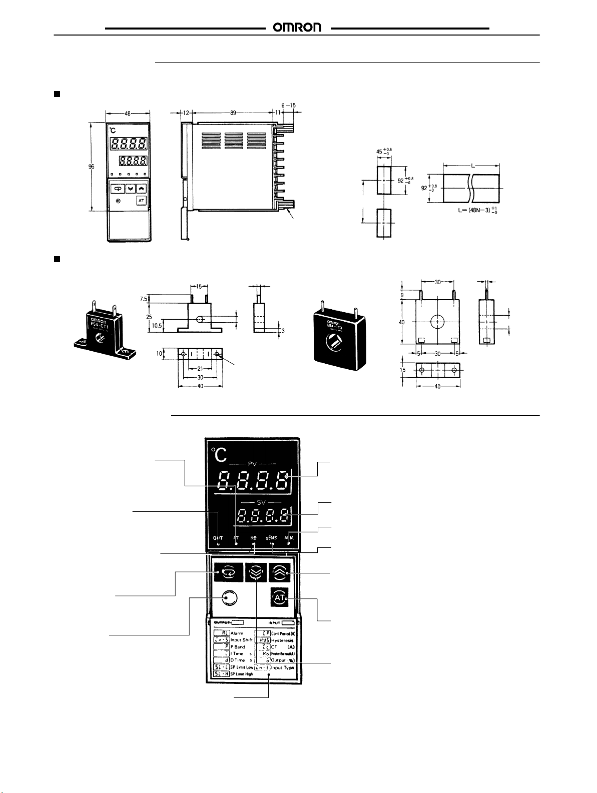
Dimensions
Note:
All units are in millimeters.
Temperature Controller
Current Transformer
E54–CT1 E54–CT3
5.8
dia.
2.8 dia
Mounting
screw
120 min.
Panel Cutout
Side-by-side Mount
ing of N Controllers
E5EX–H
2.36 dia
-
12
dia.
Nomenclature
Auto-tuning
Flashes on and off about every
second when auto-tuning is taking
place.
Output Indicator
Lit
when the control output is
Heater Burnout Indicator
Lights when a heater burnout is
detected
Display
Use
this key when
play
to the next parameter
Level Key
Press for 2 seconds minimum to
change levels to set different
groups
Indicator
ON.
and stays lit until reset.
Key
shifting the dis
.
of parameters.
-
Front Cover
Two,
3.5 dia. holes
Process V
Displays not only the process temperature but also indicates the parameter being displayed on the SV display
and error messages.
Set V
Displays set temperature and other parameters.
Alarm Indicator
Lit when the alarm output is ON.
Sensor Error Indicator
Lights when sensor malfunctions
Up Key
When pressed, increases the set temperature or other
parameters. Successively increases the value when
held
Auto-tuning Key
Press
has
1
second or more during auto-tuning to stop auto-tuning.
Down Key
When
perature
sively decreases the value when held
down.
alue (PV) Display
alue (SV) Display
down.
this key for 1 second or longer when PID operation
been designated to start auto-tuning. Press this key for
pressed, decreases the set tem
or
other parameters. Succes
-
-
4
Page 5
E5EX–H
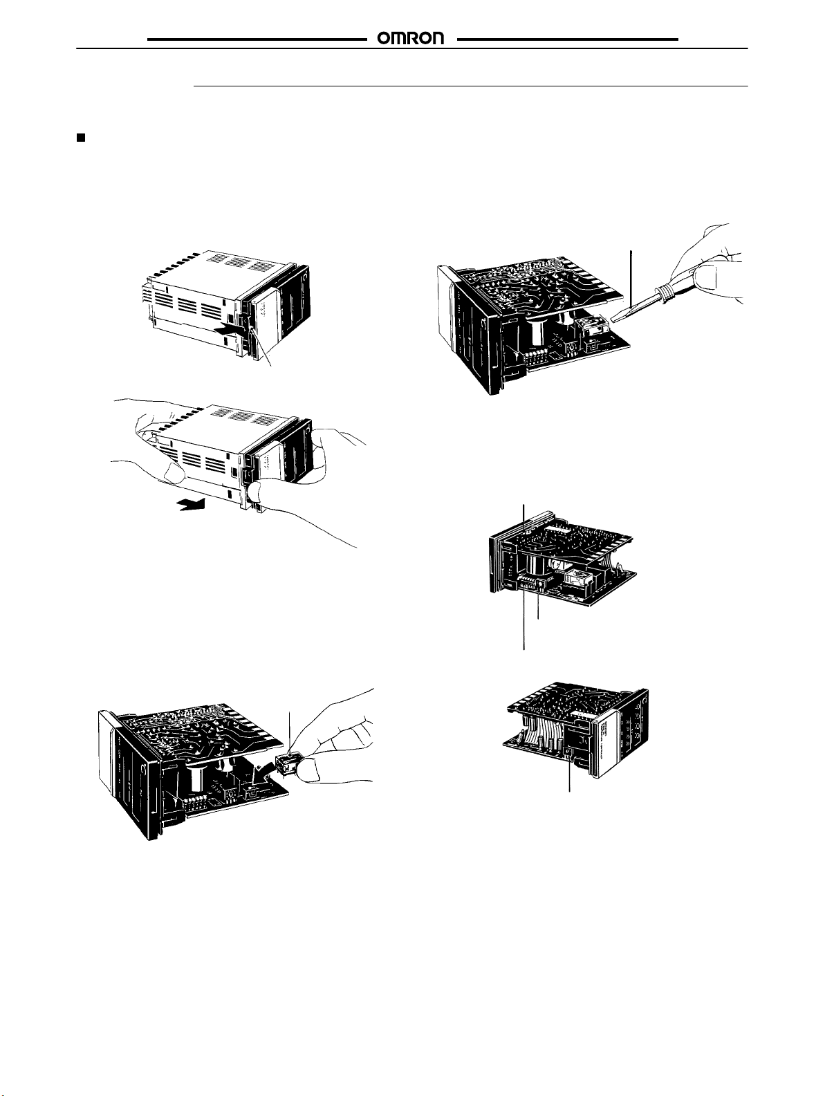
Operation
NOTICE: Always turn of
Accessing Switches and Selectors
Before
supplying power to the T
functions,
must
1.
and alarm mode. The T
be ordered separately
Remove the internal mechanism from the housing. Lift the
internal
mechanism while pressing the hook at the bottom of
the
front panel.
f the power supply to the T
emperature Controller
emperature Controller must be equipped with one of the six
.
Hook
, the selectors and switches shown below must be set to specify the temperature sensor
emperature Controller before changing any switch settings.
Control Output Units. The Control Output Unit
T
o remove a Control Output Unit, push it up with the tip of a
flat-bladed screwdriver as illustrated below
Flat-blade
screwdriver
3.
Three
internal switches must be set: the temperature sensor
selector, the operating mode selector, and the alarm mode
selector.
switches on the internal mechanism.
The following figure shows the locations of internal
E5EX–H
,
.
Pull out the internal mechanism while holding
down the hook with your finger
2.
Connect
a Control Output Unit to the vacant socket
the printed circuit boards (see the figure below). A white
square
is marked
the
Unit with this
arrow
in the figure below
on the Control Output Unit. Be sure to install
marking facing the direction indicated by the
.
.
Mount the Control Output Unit
with this mark facing the di
rection indicated by the arrow
on one of
.
Protection switch (SW101)
Alarm mode selector (SW205)
Operating mode selector (SW201)
T
emperature sensor
selector (SW206)
5
Page 6

E5EX–H
E5EX–H
Temperature Sensor Selector (SW206,
INPUT)
This
selector determines the temperature sensor to be used. It is set
to position 2 before shipment
thermocouple)
er
possible settings for temperature sensors. Refer to temperature
range
charts under
The
scale displayed (°C or °F) is set on the operating mode selector
Switch
setting
0 R
1 S
2 K
3 J
4 T
5 E
6 JPt100*
7 Pt100*
8 L
9 U
*JPt100: 100°
**Pt100:
temperature sensor
Temperature
sensor
C/139.16 Ω (JIS (Japan Industrial Standard)).
100°
C/138.5
to designate a K-type (chromel-alumel
. The
following table lists the oth
Ordering Information
code
0 to 1,700 0 to 3,000
0 to 1,700 0 to 3,000
–200 to 1,300 –300 to 2,300
–100 to 850 –100 to 1,500
–200 to 400 –300 to 700
0 to 600 0 to 1,100
–99.9 to 450.0 –99.9 to 800.0
–99.9 to 450.0 –99.9 to 800.0
–100 to 850 –100 to 1,500
–200 to 400 –300 to 700
Ω (DIN, JIS).
for further information.
T
emperature range
°C °F
Function
Operating mode
Control output
.
Input shift
Not used.** 4
Indication 5 ON
PID display 6 ON Enabled
*PID with 2 degrees of freedom
**Always
operate with pin 4 OFF
sult
in malfunction.
Pin
number
1 ON
2 ON
3 ON Enabled
Pin
setting
OFF
OFF
OFF Disabled
Leave turned OFF
OFF
OFF Disabled
. Operating with pin 4 ON could re
Control setting
ON/OFF operation
PID operation*
Normal (cooling)
Reverse (heating)
°F
°C
.
-
Operating Mode Selector (SW201,
FUNCTION)
This
DIP switch selects the operational aspects listed in the follow
ing
table.
-
6
Page 7

E5EX–H
Alarm Mode Selector (SW205: ALM)
An
alarm mode selector is provided. T
2
before shipment, i.e., the upper-limit alarm mode.
en alarm modes, listed in the following table, can be selected using this switch. The switch is set to position
E5EX–H
Switch
setting
0 Alarm
1
2
3
4
5
6
7
8
Alarm operation
Upper- and lower-limit
alarms
Upper-limit alarm
Lower-limit alarm
Upper- and lower-limit
range alarm
Inverse upper- and
lower-limit alarm with
standby sequence
Upper-limit alarm with
standby sequence
Lower-limit alarm with
standby sequence
Event alarm
Mode (SW205)
No display
)--(
---(
)ĆĆ---
-()-
3--e
---e
3---
1--(
Display
Alarm output
OFF –––
XX
SP
X
X
XX
XX
X
X
Y
Thermocouple: 0° to
9,999°
Platinum resistance
thermometer: 0° to
999.9°
(See Note 1.)
Thermocouple: –999° to
9,999°
Platinum resistance
thermometer: –99.9° to
999.9°
Thermocouple: 0° to
9,999°
Platinum resistance
thermometer: 0° to
999.9°
(See Note 1.)
Thermocouple: –999° to
9,999°
Platinum resistance
thermometer: –99.9° to
999.9°
Setting range
9
Note: 1.
0
X
X
SP
SP
See Note 2.
Proportional alarm
the proportional alarm function is used for cooling control, so that
PB: proportional band (fixed to 42
Proportional period is 20 seconds.
The operation of the alarm is not af
2 of the operating mode selector (SW201).
X
SP
When the tempera
°C)
fected by pin
Proportional alarm
If a negative value is set as X, operation will be as follows:
Lower-limit alarm
Upper-limit alarm
2. The
alarm mode selector can be used to select the proportional alarm mode. The proportional alarm function is initiated when the
temperature
ture rises to the upper limit of the proportional band (point B in the figure), the alarm output is turned ON. This alarm function is
convenient
heating
reaches the set alarm point (A in the figure below), which is the lower limit of a proportional band.
when the main setting is used for heating control, while
and cooling control actions can be easily performed.
X
SP
pro
ON
A
B
PB
-
7
Page 8

E5EX–H
E5EX–H
Standby Sequence
Alarm
functions with standby sequence suppress nuisance alarms
when
the controller is first powered up. As shown
charts
at right, the alarm output is suppressed until the temperature
exceeds
the alarm band or alarm limit one time.
in the temperature
Protection Switch (SW101, PROTECT)
When the protection switch is set to the ON position, the level key, up and down keys, and auto-tuning key will not operated. In effect, the
Temperature
Controller is write-protected and the set values (such as the alarm value) can be read out only
.
Inputting Parameters
The Temperature Controller has three indication levels, 0, 1, and 2, in which only specific parameters can be set. Level 0 is the default and is
automatically
onds
entered during power up. T
or more. The indication level mode changes as shown below
o change the mode to manipulate a dif
.
ferent group of parameters, hold down the
level key for 2 sec
-
Power up
Level 0
Press the level key. Press the level key. Press the level key.
–––––––
Process temperature,
alarm value, input shift,
PID constants
Setting limits, control peri
od, hysteresis, heater cur
rent, heater burnout set
ting
Level 0
In
this
mode, parameters such as the alarm values, PID constants,
and input shift values
ters are being set or changed, the new values are displayed on the
SV display
ing the display key the required number of times. Note that the PID
constants
lector
ON position. (The flow chart shown below assumes the settings are
as
. The parameter to be manipulated is selected by press
are displayed
DIP switch (SW201) is set
preset at the factory
Process temperature
can
be set or changed. When these parame
only when pin 1 on the operating mode se
to the OFF position and pin 6 to the
.)
Power up (temperature
setting)
Press a.
al
Alarm value
Press a.
-
-
-
Level 1 Level 2
–––––––
After
PID constants can be manually set or changed, provided pin 6 on
the internal operating mode selector (SW201) has been set to the
ON
shown
Control output variable,
temperature sensor type,
alarm mode
al has been displayed, press the display key again. Then the
position. The message displayed on the PV
below each time the display key is pressed.
Process temperature
al
p
i
d
–––––––
display changes as
Power up (temperature
setting)
Press a.
Alarm value
Press a.
Proportional band
Press a.
Integral time
Press a.
Derivative time
Press a.
8
Page 9

E5EX–H
E5EX–H
Alarm: al
When al is displayed on the PV display
output
can be set on the SV display
or
falls below the set alarm value, the corresponding alarm output is
produced and the ALM indicator on the front panel lights. Usually,
the
alarm value is set as a deviation from the set temperature (set
point), but it can also be set as an absolute value when the event
alarm
mode is selected. Set the alarm
key
while al is displayed. The message is not displayed if the alarm
mode
selector is set to position 0.
Proportional Band: p
While p is displayed on the PV display, the proportional band (P
constant)
will
range from 0.0° to
ting
Integral T
The
is
I constant.
1
Derivative T
The
ter
change
onds
Input Shift: in-5
When pin 3 on the internal operating mode selector DIP switch
(SW201) is set to the ON position, the input shift function can be
used.
measured
the
can be changed using the
be displayed on the SV display
is 40.0
integral time (I constant) can be changed when the character
displayed on the PV display
second. The factory setting is 240 seconds.
derivative time (D constant) can be changed
d is displayed on the
the D constant.
in units of 1 second. The factory setting is 60 seconds.
This function is used to shift the temperature
following table:
999.9
°C/°F
°C/°F.
ime (Reset T
The
allowable range is from 0 to 3,999 seconds in units of
ime (Rate T
value by a desired
in units of 0.1
ime):
i
. Use the up or down key
ime):
PV display
The allowable range is from 0 to 3,999 sec
value, as illustrated by the examples in
, the alarm
. When the temperature exceeds
value by using the up or down
up or down key
. The P constant
d
. Use the up or down key to set or
value for alarm
. The new value
can be set in a
°C/°F
. The factory set
to change the
when the charac
display from the
Power up (temperature
Process temperature
Press a.
al
Press a.
in-5
Press a.
p
Press a.
i
Press a.
d
i
While
in-5 is
by
which the measured
set and displayed on the SV display. The range in which the input
shift can be set differs depending on whether a thermocouple or
-
temperature resistance thermometer is used as the temperature
sensor.
-
–999
tance thermometer is used. The input shift function remains ef
tive even if pin 3 on the operating mode selector DIP switch
(SW201)
has been set. If the displayed temperature does not need to be
shifted,
displayed on the PV display
When a thermocouple is used, the allowable range is from
to 9,999
°C/°
is changed to the OFF position after the input shift value
set 0
°C/°
Press a.
temperature is shifted and displayed, can be
F in
units of 0.1
F in response to
setting)
Alarm value
Input shift
Proportional band setting
Integral time setting
derivative time setting
, the input
°C/°
F when a temperature resis
in-5.
shift, the value
-
fec-
Input shift value
0 (without shift)
10 (of
fset by 10
–10 (of
fset by
–10°C)
This function can be used mainly for fine tuning compensation,
while
leaving the
pressing
°C) 100°C 110°C
set temperature unaf
the display key three times in display level 0, as follows:
Temperature
measured by
sensor
100°C 100°C
100°C 90°C
fected. Select this function by
temperature
Displayed
9
Page 10

E5EX–H
E5EX–H
Level 1
In this level, the upper- and lower-limit values of the temperature
range, control period, hysteresis, heater current, and heater burnout
alarm can be set.
When pin 1 on the operating mode selector (SW201) is set to the
OFF position (PID action), the temperature setting range limit values,
control period, heater current, and heater burnout alarm value
can
be set or changed. Any of these
pressing
display key the required number of times as follows:
5l-l
Press a.
5l-h
Press a.
cp
Press a.
ct
Press a.
hb
Press a.
Lower/Upper Limits of T
–200 0
SL–L SL–H
Basically, the temperature range that can be measured is determined
by the temperature sensor to be
K-type (chromel-alumel thermocouple) temperature sensor is selected,
the measurable range is from –200°C to 1,300°C. However
this
temperature range can be narrowed, say
this, set the lower-limit value of the temperature setting range, in this
case to 0°C, on the SV display by using the up or down key while
5l-l is displayed on the PV display. Similarly, set the upper-limit
value, 400°C, while 5l-h is displayed. If the process temperature
falls below the set lower-limit value or exceeds the set upper-limit
value,
it is displayed on the PV display provided it is
perature
Control Period: cp
To use a control period, pin 1 on the operating mode selector
(SW201)
the
from
seconds. When a Voltage Output Unit is used, it is recommended
that
seconds), so that the control action can be performed more accurately.
range of the temperature sensor
must be set to the
PV display
1 to 99 seconds in units of 1 second. The factory setting is 20
the control period be set to 20 seconds or less (ideally
, the control period can be set or changed
emperature Range:
parameters can be selected by
Lower-limit value of temper
ature setting range
Upper-limit value of tem
perature setting range
Control period
Heater current
Heater burnout alarm
sl-l, sl-h
400
used. For example, when a
OFF position. When cp is displayed on
1,300
, to 0°C to 400°C. T
within the tem
.
-
-
o do
in a range
, about 2
,
-
Heater Burnout Alarm: ct
Set
a
burnout current value to determine disconnections of the heat
er. Firstly, a current measured in the heater current value mode is
displayed
with
rent
Use display key and set the PV display to hb. The difference between
should
tect the disconnection of the heater may be not stable. The value
can
Note
Heater Burnout Alarm and Sensor Abnormality Alarm
in amperes. The normal current value is the current value
the control output ON. Disconnect the
value and obtain the set value from the following:
Normal
current value + Current value
the normal current
be 2.5 A minimum. If it is less than 2.5 A, the operation to de
be set with in increments of 0.1 A from 0.0 to 50.0 A.
1:Do not allow a current of more than 50 A to flow in the Con
troller;
the maximum continuous heater current is 50 A.
2: Set
the value to 0.0 A if the heater burnout alarm is not used,
in
which case the alarm will not function at all.
Alarm Heater burnout
Output terminal
Output ON
Output
display
monitor
Output retention
function
Output reset
Influence on con
trol output/alarm
output
-
,
hb
heater and read the cur
with disconnected heater
2
and the one with the disconnected heater
alarm
T
erminal output is ON when either alarm
is ON.
When a heater
burnout
is
detected.
hb
on front panel is
lit.
Yes No
Set heater burnout
alarm value to 0.0
A or switch power
OFF and then turn
on power
None
.
Sensor
abnormality
alarm
When sensor is in
error.
5en5
on front panel
is lit.
Output is OFF
when sensor ab
normal condition is
solved
Control output:
OFF; Alarm output:
ON (proportional
alarm output is
OFF)
-
-
-
-
-
Control
ON
OFF
10
output
When control period is
set to 20 seconds
20 seconds
Page 11

E5EX–H
E5EX–H
Connected
alarm
Sensor abnormality
Heater burnout
*This wiring must be passed through the hole of the special current
transformer. The current transformer can be connected to the sensor in any polarity
*Wire through the hole on the Current
Transformer.
the Temperature Controller can be connected with wires without polarity.
to T
Temperature
Controller
The Current T
emperature Controller
Heater load
Input
sensor
ransformer and
Connected to Temperature Controller.
*Current
Output
controller
200VAC
transformer
2. ON/OFF Control
When
pin 1 on the operating mode selector (SW201) is set
to the ON
position, the temperature setting range limit values, hysteresis,
heater current, and heater burnout alarm value can be set or
changed.
play
Any of these parameters can be selected by pressing dis
key the required number of times as follows.
5l-l
Lower-limit value of temper
ature setting range
-
Press a.
5l-h
Upper-limit value of tem
perature setting range
-
Press a.
hys
Hysteresis
Press a.
ct
Heater current
Press a.
hb
Heater burnout alarm
Press a.
Of the above parameters, only the hysteresis, which is described
below, differs from the parameters for PID control. Refer to 1. PID
Control
for details on other parameters.
Hysteresis:
The
hysteresis value for the ON/OFF control action can be
range
hys
from 0.0° to 999.9
°C/°
F while
hy5
is displayed on the PV dis
set in a
play. Use the up or down key to do this. The factory setting is
0.8°C/°F.
-
-
Connected to heater.
Reverse operation
(heating control)
Low temperature High temperature
Normal operation
(Cooling control)
Hysteresis
SP
Hysteresis
SPLow temperature High temperature
11
Page 12

E5EX–H
E5EX–H
Level 2
In level 2 the control output variable, temperature sensor, and
modes
for alarm output can
itoring
level only and thus no parameter can be changed. When the
level
key is pressed for more than 2 seconds after power up,
displayed on the PV display. After this message has been displayed, holding down the Level key again for 2 seconds or more
causes
o to be displayed on the PV display
been displayed, the control output variable, selected temperature
sensor, and alarm modes can be monitored each time the display
key is pressed, as follows:
o
in-t
al
Control Output V
When
the T
amount
Temperature
When in-t is displayed on the PV display, a message identifying
the
perature
The following table shows the messages that may be displayed:
emperature Controller enters level 2, the control output
is displayed on the SV display in a
Sensor:
selected temperature sensor
sensor selector (SW206), is displayed on the SV display
be monitored. Note that level 2 is a mon
. When this message has
Control output variable
Press a.
T
emperature sensor
Press a.
Alarm mode
Press a.
ariable:
o
range of 0.0% to 100.0%.
in-t
, i.e., the present setting of the tem
5l-l is
Display
-
No display No alarm
)--(
---(
)---
-()-
3--e
Upper- and lower-limit
alarms
Upper-limit alarm
Lower-limit alarm
Inverse upper- and lower-
limit alarm
Upper- and lower-limit
alarms with standby se-
Alarm mode
quence
---e
3---
1--c
pro
.
Upper-limit alarm with
standby sequence
Lower-limit alarm with
standby sequence
Event alarm
Proportional alarm
Display Sensor
r pr
5 pr
k ca
j ic
t cc
e cr
jpt
pt
l ic
u cc
*Meets
JIS 1981.
**Meets JIS 1989, DIN.
AL (Alarm Mode):
While
al is displayed on the PV display in level 2,
fying
the mode for alarm output or the present setting of the corre
sponding
play.
pear
alarm mode selector
The following table shows the possible messages that may ap
on the SV display
al
.
R
S
K
J
T
E
JPt100*
Pt100**
L
U
a message identi
(SW205) is displayed on the SV dis
-
-
-
-
12
Page 13

E5EX–H
E5EX–H
Beginning Control Operation
Temperature
er
is turned
the parameters that have been input. To operate the Temperature
Controller
and
then on again.
Auto-tuning
When
Controller
tuning is taking place, the auto-tuning indicator on the front panel will
flash. The Temperature Controller executes control based on the
set
PID constants (factory set to P = 40°C, I = 240 seconds, and D =
60
seconds) until the temperature of the controlled system reaches
the
set temperature. After that, the T
ically
the
automatic tuning of the PID constants has been completed, the
auto-tuning
Auto-tuning
ture Controller is performing reverse (heating) or normal (cooling)
operation. To stop auto-tuning, hold down the AT key again for 1
control is begun
on, and temperature control is carried out according to
after all the parameters are input, turn the power off once
the A
T key is pressed for 1 second or more, the T
automatically starts tuning the PID constants. While auto-
adjusts the PID constants using the limit cycle method. After
display goes out.
can be carried out regardless of whether the T
for the set values as soon as the pow
emperature
emperature Controller
automat
empera-
-
-
Advanced PID Control
Advanced
ward (FF)
ventional PID controller responds to disturbance (d) to quickly
achieve
control,
This is prevented in advanced PID control because the feed-forward loop is not affected by disturbance. Here, the feed-forward
loop
out
PID control with two degrees of freedom adds a feed-for
loop to the conventional PID controller
stability
, it overshoots the target because it lacks suf
as shown below
operates from the target
overshooting.
.
value (r) to achieve fast response with
. Whereas the con
-
-
ficient
-
second
or more. Automatic tuning can be executed at any time: on
power
up, while the temperature is rising, and after the control ac
tion has stabilized.
Limit Cycle Method
Set
temperature
AT key is pressed
Limit cycle method:
The
optimum
ing
the control output variable and generating external oscillation.
Old PID
constants
A
T indicator blinks
PID constants are calculated by this method by vary
New PID constants
-
-
r
Normal
PID
operation
E5EX–H
FF
+
PID
–++
If response to target value improves, response to external
disturbances degrades.
If response to external disturbances value improves, response to target value degrades.
Excellent response to both target value and external
disturbances.
d
–+
Control
object
y
13
Page 14

E5EX–H
Error Messages
E5EX–H
The Temperature Controller is provided with self-diagnostic functions, and will display
an
error
.
Message
ffff
----
5.err (flashes)
e111 (flashes)
e333 (flashes)
*When the J thermocouple is used, however
range
by more than 70
**When the temperature resistance thermometer is used, this message is displayed when the temperature has fallen to –99.9
The T
emperature Controller displays the following error message in case of a Current T
Message
ffff
Input temperature has risen beyond the upper limit of
the temperature range by more than 20
Input temperature has fallen below the lower limit of
the temperature range by more than 20
The
thermocouple has burned out or short-circuit bar
has been removed. The platinum resistance thermom
eter has burned out or A and B have been short-cir
cuited.
Memory failure (
has occurred. T
if recovery is not made by turning power of
on again.
°C.
CT input current is
over 50.0 A
emperature Controller must be repaired
Cause Control output
Cause Control output Alarm output
°C
°C.
-
e111
) or A/D converter failure (
, this error message is not displayed
Normal
e333)
f once and
Retains condition there was before
output and sensor abnormality alarm output can function nor
mally.
the following error messages on the PV display in case of
OFF during reverse
(heating) operation
On during normal (cool
ing) operation
On during reverse
(heating) operation
OFF during normal
(cooling) operation
OFF
-
OFF OFF
until the temperature has risen above the set temperature
ransformer input error
Heater disconnection alarm output
Sends alarm signal in accor
dance with the set alarm
-
mode.*
Sends alarm signal in accor
dance with the set alarm
mode.*
Sends alarm signal in accor
dance with the set alarm
mode. Proportional alarm out
put is OFF
ffff
, however
.
is displayed. Alarm
-
-
-
-
.
°C.
-
Installation
Wiring
*Current Transformer must be either
E54–CT1 or E54–CT3.
**Heater burnout alarm output terminal is
used to indicate both heater disconnection
and sensor errors.
For SSR
output
For voltage
output
For relay
output
40 mA,
12 VDC
Alarm output
Heater burnout alarm output**
Current Transformer*
Control
output
FG
Ground FG terminal 18 to avoid ambient noise.
Do not connect unused terminals.
100 to 240 VAC, 50/60 Hz
Use these terminals when connecting a
platinum
resistance thermometer (remove short
bar from terminals 13 and 14).
Use these terminals when connecting a
thermocouple (do not remove short bar
from terminals 13 and 14).
14
Page 15

E5EX–H
Precautions
Mounting
The dimensions of the Temperature Controller conform to DIN
43700.
Recommended panel thickness is 1 to 8 mm.
Do not install the Temperature Controller in a location exposed to
excessive
ject
tures.
erates
ers.
Attach
and
mounting
dust or corrosive gases. Moreover
to heavy vibration
Isolate the T
strong, high-frequency
the two mounting fixtures supplied with E5EX–AH on the top
bottom
of the T
fixtures with your fingers.
or shock, water or oil spray
emperature
emperature Controller
Controller from equipment that gen
noises such as high-frequency weld
, avoid locations sub
, or high tempera
. T
ighten the screws of the
short-circuit bar shown in the terminal block diagram
ing.
Use lead wires having a small resistance for temperature
tance
thermometers.
Be sure to remove the short-circuit bar from the terminals when a
temperature
-
-
Sequenced Circuits
Several
er
has been supplied to the T
this time delay into consideration when designing sequenced circuits
resistance thermometer is used.
seconds are
which incorporate a T
required until the relay is turned ON after pow
emperature Controller
emperature Controller
. Therefore, take
.
Terminal Layout Diagram on the Housing
The Temperature Controller allows an input and output device to be
freely selected. Use the terminal layout diagram attached on the
housing
of the T
mounted
follows:
emperature Controller to identify the output
in the Temperature Controller
, by making the diagram as
Check here with a felt-tip pen.
E5EX–H
on the hous
resis
device
-
-
-
Connection Examples
With
Solderless T
Use M3.5 solderless terminals with the Temperature Controller’s
M3.5 self-rising pressure plate screws.
Solder-dipped Leads:
Strip
6 to 12 mm of
Do
not tighten the
block
of the T
wires
can be connected to all the
erminal:
the lead wires and carefully arrange the wire tips.
terminal screw with excessive force. The terminal
emperature Controller is
constructed so that the lead
terminals from the same direction.
Top
Bottom
Temperature Sensor Connection
To
reduce induced
sensor
to the T
er
lines and load lines.
Use the specified compensating conductors for thermocouples.
When
using a thermocouple as the temperature
noise, the lead wires connecting the temperature
emperature Controller must be separated from pow
sensor
, attach the
-
Stickers
Stickers
indicating the
Control
Output Unit (R, S,
Controller.
ing
Temperature
Attach these stickers on the front panel as shown,
the temperature sensor and Control
Controller can be easily discerned.
Sticker identifying
Control Output Unit
temperature sensor type (R, S, K, J, etc.) and
and Q) are supplied with the T
Output Unit mounted in the
Sticker identifying
temperature sensor
emperature
allow
-
15
Page 16

E5EX–H
E5EX–H
ALL DIMENSIONS SHOWN ARE IN MILLIMETERS.
To
convert millimeters into inches, multiply by 0.03937. T
o convert grams into ounces, multiply by 0.03527.
Cat. No. H49–E1–1 In the interest of product improvement, specifications are subject to change without notice.
OMRON Corporation
Temperature Control Devices Division
9th Fl., Osaka Center Bldg.
4-1-3, Kyutaro-machi, Chuo-ku,
Osaka 541 Japan
Phone: 06-282-2500 Fax: 06-282-2749
Telex: 522-2484 OMRONO J
16
Printed
in Japan
0590–3M (0590)
 Loading...