

Page 1
Temperature Controller
E5EX-BA/A02/A03
Compact 96 x 48-mm (DIN) Temperature
Controller with Communication
Capabilities and 8 Memory Banks
E5AX-BA/BAH
Advanced PID control with feed-forward circuitry
(2-PID) for optimum control.
Eight
memory banks for easy parameter changes.
Communication capabilities for centralized data
management.
Interchangeable
Output Units to expand
Controller
applicability.
Input sensor selectable via internal switches.
Available with heater burnout detection.
Ordering Information
An
Output Unit must be connected to all Controllers.
An Output Unit and Current T
Current Output Units and Current T
Current Output Units cannot be used to control the outputs of E5EX models that incorporate a heater burnout alarm.
Be sure to specify Output Unit and Current T
Example: E5EX-BA
TC, Relay Output Unit E53-R, Current T
Temperature Controllers
Thermocouple
Item 8
W
ithout heater
burnout alarm burnout alarm
Model E5AX-BATC
E5EX-BATC
ransformer must also be connected to Controllers with a heater burnout alarm.
ransformer are sold separately
ransformer as necessary when ordering.
banks
W
ith heater
E5AX-BAHTC
E5EX-BAHTC
.
ransformer E54-CT1
Communications
RS-422 RS-485
W
ithout heater
burnout alarm
E5EX-A02TC E5EX-AH02TC E5EX-A03TC E5EX-AH03TC
W
ith heater
burnout alarm
W
ithout heater
burnout alarm
W
ith heater
burnout alarm
Platinum Resistance Thermometer
Item 8
W
ithout heater
burnout alarm burnout alarm
Model E5AX-BAP
E5EX-BAP
banks
E5AX-BAHP
E5EX-BAHP
W
ith heater
Current Transformers (CT)
Hole
diameter
Model E54-CT1 E54-CT3
Note:
The E54-CT2 cannot be used.
5.8 mm
12.0 mm
Communications
RS-422 RS-485
W
ithout heater
burnout alarm
E5EX-A02P E5EX-AH02P E5EX-A03P E5EX-AH03P
W
ith heater
burnout alarm
W
ithout heater
burnout alarm
W
ith heater
burnout alarm
1
Page 2
E5AX-BA/BAH/E5EX-BA/A02/A03
Temperature Ranges
Thermocouple
Input
(switch
selectable)
Range °C
°F
Resolution
(°C/°F)
(main settings
and alarm)
Platinum Resistance Thermometer
Input (switch selectable)
Range °C
Resolution (
settings and alarm)
°C/°
R
Platinum
vs.
platinum.
rhodium
13%
0 to 1,700 0 to 1,700 –200 to 1,300 –100 to 850 –200 to 400 0 to 600 100 to 1,800 0 to 1,300
0 to 3,000 0 to 3,000 –300 to 2,300 –100 to 1,500 –300 to 700 0 to 1,100 300 to 3,200 0 to 2,300
1
°F
F) (main
S
Platinum
vs.
platinum.
rhodium
10%
–99.9 to 450.0
–99.9 to 800.0
0.1
Specifications
K (CA)
Chromel vs.
alumel
JPt100/Pt100
J/L (IC)
Iron vs.
constantan
T/U (CC)
Copper vs.
constantan
E5AX-BA/BAH/E5EX-BA/A02/A03
E (CRC)
Chromel
vs.
constantan
B
Platinum.
rhodium
30% vs.
platinum.
rhodium 6%
N
Nichrosil
vs. nisil
Ratings
Supply
voltage
Operating voltage range
Power consumption
Input
Current T
Control output
Control mode
Alarm output
Heater burnout alarm output
Setting method
Indication method
Bank selection
Other functions
ransformer input
100 to 240 V
85% to 1
Approx. 10 V
Thermocouple (R/S/K/J/T/E/B/N/L/U) or platinum resistance thermometer (Pt100/JPt 100),
selectable
Connect an exclusive Current T
See Control Output Unit Ratings (Control Output Units are sold separately
PID control with feed-forward circuitry (feed-forward PID) with auto-tuning or ON/OFF
Relay output, 2 independent SPST
Relay output, SPST
Digital setting via Up and Down Keys
Digital indications (character heights: PV
SV
: green, BK: orange)
No voltage, contact signal input; contact impedance: 100 Ω max.
Upper and lower limits for set value
Key protection
Input shift
Scale selection (
Normal and reverse output selection
Bank selection
Bank copy
W
atchdog timer function (Detects failures in the CPU and restores the CPU.)
AC, 50/60 Hz
10% of rated supply voltage
A (at 100 V
AC) to 15 V
ransformer unit (E54-CT1 or E54-CT3).
-NO; 1 A, 250 V
°C/°F)
A (at 24 V
-NO contacts; 3 A, 250 VAC (resistive load)
AC (resistive load)
AC)
: 1
1 mm, SV
.)
: 8 mm, BK: 8 mm) (color PV
: red,
Output Unit Ratings
Relay Output Unit E53-R SPDT
SSR Output Unit E53-S SPST
Voltage Output Unit E53-Q
(for driving SSR) E53-Q3
E53-Q4
Current Output Unit* E53-C
*Current Output Units cannot be used to control the outputs of E5EX models that incorporate a heater burnout alarm.
2
; 5 A, 250 V
-NO; 1 A, 75 to 250 V
40 mA max., 12 VDC; NPN (with short-circuit protection)
20 mA max., 24 VDC; NPN (with short-circuit protection)
20 mA max., 24 VDC; PNP (with short-circuit protection)
4 to 20 mA, DC: 600 Ω max.; resolution: 212
AC (resistive load)
AC; leakage current: 1.5 mA max. (at 200 V
AC)
Page 3
E5AX-BA/BAH/E5EX-BA/A02/A03
Current Transformer Ratings
Max.
continuous heater current
Dielectric strength
V
ibration resistance
Weight
Accessories (E54-CT3 only)
50 A
1,000 V
AC (for 1 min)
50 Hz (approx. 10G)
E54-CT1: Approx. 1
Contact: 2; Plug: 2
1.5 g; E54-CT3: Approx. 50 g
Controller Characteristics
Setting
accuracy*
Indication accuracy
Hysteresis 0.0°
Proportional band
Integral (reset) time
Derivative (rate) time
Alarm output setting range
Control period
Sampling period
Output refresh period
Display refresh period
Input shift range
Insulation resistance
Dielectric strength
V
ibration resistance
Shock resistance
Ambient temperature
Ambient humidity
Memory protection
Enclosure ratings
Weight
*The
accuracy of U thermocouples under temperatures from –150° to 400°C (–240° to
below
–150°C (–240°F). The accuracy of R and S thermocouples under 0° to 200°C (0° to 400°F) is
B
thermocouple below 400°C (750°F) is not guaranteed.
(±
0.3% of set value or
(±
0.3% of indication value or
the indicated value, because no relative error exists between both values.)
to 999.9
0.0°
to 999.9
0 to 3,999 s (in units of 1 s)
0 to 3,999 s (in units of 1 s)
Thermocouple: –999° to 9,999
Platinum resistance thermometer: –99.9° to 999.9
Pulse output: 1 to 99 s (in units of 1 s)
500 ms
500 ms
500 ms
–99.9°
20 MΩ min. (at 500 VDC) (measured with a Control Output Unit attached)
2,000 V
Control Output Unit attached)
Malfunction:
Destruction:
Malfunction:
Destruction:
Operating: –10°
Storage: –25°
Operating: 35% to 85%
Non-volatile memory
Front panel:
Rear case:
Terminals:
Approx. 310 g; mounting bracket: approx. 50 g
°C/°
°C/°
to 999.9
AC, 50/60 Hz for 1 minute between terminals of dif
2 to 55 Hz, 2G 10 minutes each in X, Y
10 to 55 Hz, 0.75-mm double amplitude 2 hours each in X, Y
200 m/s2 3 times each in 6 directions
300 m/s2 3 times each in 6 directions
IEC standard IP50
IEC standard IP20
IEC standard IP00
±1°
C, whichever greater) ±1 digit max.
±1°
C, whichever greater) ±1 digit max. (Set value coincides with
F (in units of 0.1
F (in units of 0.1
°C/°
F (in units of 1
to 55°C (with no icing)
to 65°C (with no icing)
°C/°
°C/°F)
°C/°
F (in units of 1
°C/°F)
F) (during ON/OFF control action)
E5AX-BA/BAH/E5EX-BA/A02/A03
°C/°F)
°C/°
700°F) is
F (in units of 0.1
ferent polarities (measured with a
, and Z directions
±2°
C (
±3.6°
±3°
C (
±5.4°
°C/°F)
, and Z directions
F) ±1 digit. Accuracy is reduced
F) ±1 digit. The accuracy of the
Output Unit Characteristics
Relay
unit life expectancy
Mechanical:
Electrical:
10,000,000 operations min.
100,000 operations min.
3
Page 4
E5AX-BA/BAH/E5EX-BA/A02/A03
E5AX-BA/BAH/E5EX-BA/A02/A03
Heater Burnout Detection Characteristics
Max.
heater current
Monitor accuracy of input current
Heater burnout detection setting range
Heater current monitor range
Min. detectable ON time
*Heater
burnout is not detected when current is set to 0.0 A; the burnout alarm will be automatically turned ON when current is set to 50.0 A.
**When
the control output is ON for less than 200 ms, heater burnout is not detected and heater current is not measured.
50 A, single-phase
±
5% of full scale ±1 digit max.
0.1 to 49.9 A (in units of 0.1 A)*
0.0 to 50.0 A
200 ms**
Communications
Protocol RS-422 RS-485
Transmission
Synchronization method
Baud rate
T
ransmission code
Communications W
Note: 1.
method
4-wire, half-duplex 2-wire, half-duplex
Start-stop synchronization
150/300/600/1,200/2,400/4,800/9,600 bps
ASCII (7-bit)
rite to T
Controller
emperature
Read from
T
emperature Controller
Main setting, set alarm value, proportional band, integral time, derivative time,
Auto-tuning (A
T) start/stop, heater burnout alarm set value
Main setting, set alarm value, proportional band, integral time, derivative time, process
temperature, heater burnout alarm set value, Current T
ransformer input value, etc.
The maximum total cable length must not exceed the following limits.
RS-422: 500 m, RS-485: 500 m
2. A
maximum of 32 T
emperature Controllers can be connected to
one host computer using serial communications (RS-422). In the
case of the RS-485 serial communications, however, a maximum of 31 Temperature Controllers can be connected to one host
computer.
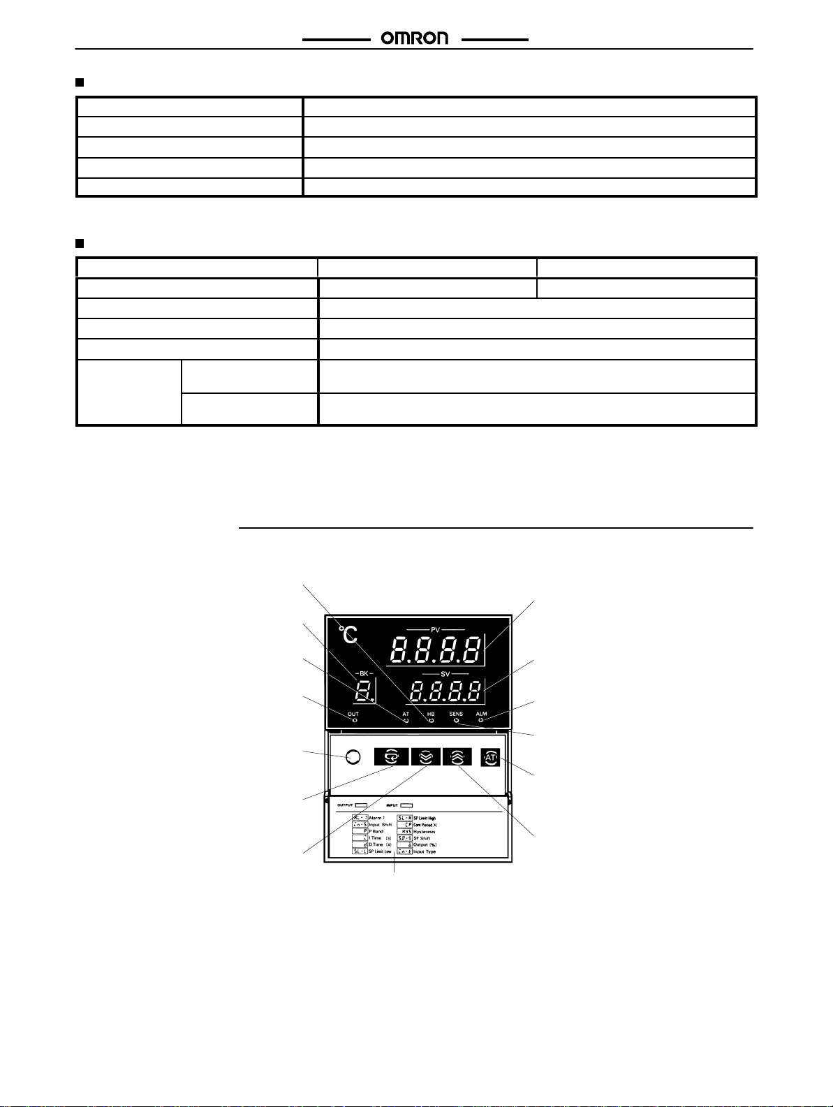
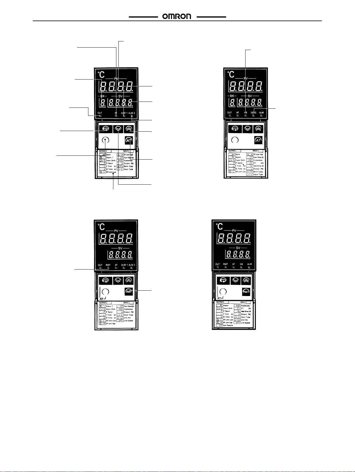
Nomenclature
E5AX-BA/BAH
Heater Burnout Indicator
Lights when a heater burnout is detected and stays lit unit reset.
Bank Number Display
Displays the present bank number.
Auto-tuning Indicator
Flashes on and off every second
when auto-tuning is taking place.
Output Indicator
Lights when the control output is
ON. Turns off when the current output unit is used.
Level Key
Press for 2 seconds minimum to
change levels to set different
groups of parameters.
Display Key
Press to shift the display to the
next parameter.
Down Key
Press to decrease the main setting
or other parameters. Successively
decrease the value when held
down.
Front cover
Process Value (PV) Display
Displays the process value, the
character for parameter being displayed on the SV display
messages.
Set Value (SV) Display
Displays the main setting and other
parameters.
Alarm Indicator
Lights when alarm output is ON.
Sensor Error Indicator
Lights when sensor error is detected.
Auto-tuning Key
Press for 1 second minimum to start
auto-tuning. Press for 1 second
minimum during auto-tuning to stop
auto-tuning.
UP Key
Press to increase the main setting or
other parameters. Successively increases the value when held down.
, and error
4
Page 5
E5AX-BA/BAH/E5EX-BA/A02/A03
E5AX-BA/BAH/E5EX-BA/A02/A03
E5EX-BA
Auto-tuning Indicator
Flashes on and off every second
when auto-tuning is taking place.
Bank Number Display
Displays the present
bank number.
Output Indicator
Lights when the control
output is ON. Turns off
when the current output
unit is used.
Display Key
Press to shift the display to
the next parameter.
Level Key
Press for 2 seconds minimum
to change levels to set different groups of parameters.
Front cover
Process Value (PV) Display
Displays the process value, the character for
parameter being displayed on the SV display,
and error messages.
Alarm 1 Indicator
Lights when alarm
output 1 is ON.
Set Value (SV) Display
Displays the main setting
and other parameters.
Alarm 2 Indicator
Lights when alarm output 2 is ON.
UP Key
Press to increase the main setting or
other parameters. Successively increases the value when held down.
Auto-tuning Key
Press for 1 second minimum to start
auto-tuning. Press for 1 second minimum
during auto-tuning to stop auto-tuning.
Down Key
Press to decrease the main setting or
other parameters. Successively decrease the value when held down.
E5EX-BAH
Heater Burnout Indicator
Lights when a heater burnout is
detected and stays lit until reset.
Sensor Error Indicator
Lights when sensor error
is detected.
E5EX-A02/-A03 E5EX-AH02/-AH03
Remote Indicator
Lights in the remote
mode. The indicator is
off in the local mode.
Remote Key
Press to communicate in
the remote mode. Press
again to set parameters
with the keys in the local
mode.
Note: Press
both the Display Key and Level Key for 1 second minimum to start auto-tuning.
Press both the Display Key and Level Key for 1 minimum during auto-tuning to stop auto-tuning.
5
Page 6
E5AX-BA/BAH/E5EX-BA/A02/A03
Operation
E5AX-BA/BAH/E5EX-BA/A02/A03
NOTICE: Always
turn of
f the power supply to the T
emperature Controller before changing any switch settings.
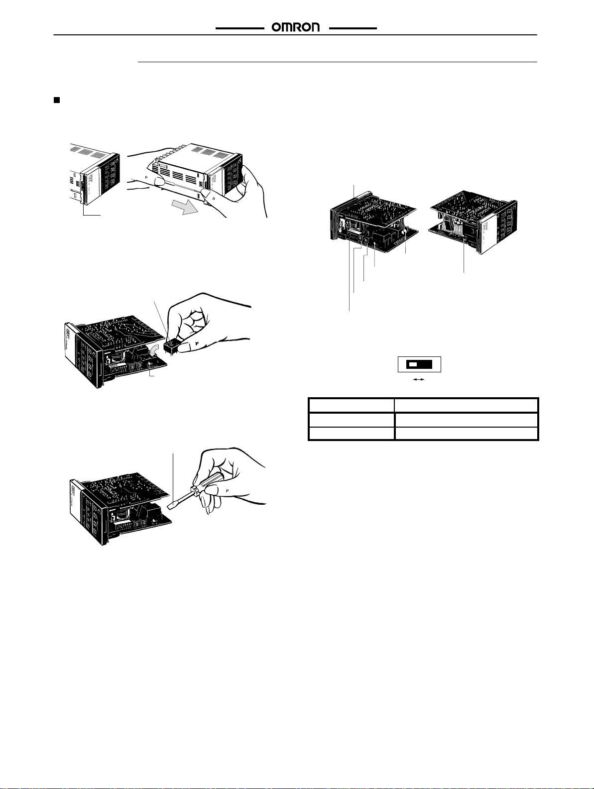
Settings
1. Remove the internal mechanism from the housing. Lift the
internal
mechanism while pressing the hook at the bottom of
the
front panel.
Hook
Pull out the internal mechanism while
holding down the hook with your finger.
2. Connect a Control Output Unit to the vacant socket on the
printed
circuit board as shown below
Mount the Control Output Unit
with the mark facing the direction
indicated by the arrow.
Set the output selector (SW205, OUTPUT
TYPE) to PULSE when a Relay, SSR, or
Voltage Output Unit is mounted. Set the
output selector to CURRENT when a
Current Output Unit is mounted.
To
remove a Control Output Unit, push it up with the tip of a flat-blade
screwdriver
as shown below
Flat-blade screwdriver
.
.
3. Six internal switches must be set on the E5EX: the function
selector, the alarm mode selectors 1 and 2, the output
selector,
terminator switch, and the input type selector
figures show the locations of these switches and the pro
The
tection switch on the internal mechanisms. The protection
switch
can be used to disable key operation.
Protection switch
(SW101, PROTECT)
Terminator switch
(SW206, TERMINATOR)
Output type selector
(SW205, OUTPUT TYPE)
Alarm mode selector 2
(SW204, ALM2)
Alarm mode selector 1
(SW203, ALM1)
Function selector
(SW201, FUNCTION)
Input type selector
(SW202 or 207)
Output Selector (SW204, OUTPUT)
OFF ON
PULSE CURRENT
Output
Setting (factory-set to OFF)
Current ON
Pulse OFF
.
-
6
Page 7

E5AX-BA/BAH/E5EX-BA/A02/A03
Input Type Selector
Thermocouple Selector (SW202, INPUT)
This
selector selects the temperature sensor to be used. It is facto
ry-set
to position 2 to designate a K-type (chromel-alumel thermo
couple)
temperature sensor
sible
settings for temperature sensors. Refer to temperature range
charts
under
Ordering Information
The scale displayed (°C or °F) is selected by the function selector
(SW201).
Switch Temperature T
setting
sensor code
0 R 0 to 1,700 0 to 3,000
1 S 0 to 1,700 0 to 3,000
2 K –200 to 1,300 –300 to 2,300
3 J –100 to 850 –100 to 1,500
4 T –200 to 400 –300 to 700
5 E 0 to 600 0 to 1,100
6 B 100 to 1,800 300 to 3,200
7 N 0 to 1,300 0 to 2,300
8 L –100 to 850 –100 to 1,500
9 U –200 to 400 –300 to 700
. The following table lists the other pos
for further information.
0
1
9
2
8
73
6
4
5
emperature range
°C °F
E5AX-BA/BAH/E5EX-BA/A02/A03
Platinum Resistance Thermometer Selector
(SW207, INPUT)
-
-
This
-
selector is factory-set to OFF to designate a JPt100-type tem
perature sensor. The settings and applicable ranges are shown
the following table.
OFF ON
Switch Temperature T
setting
sensor code
OFF JPt100
ON Pt100
emperature range
°C °F
–99.9 to 450.0 –99.9 to 800.0
–99.9 to 450.0 –99.9 to 800.0
Note: JPt100:100°C/139.16Ω
PT100: 100°C/138.50Ω
-
in
7
Page 8

E5AX-BA/BAH/E5EX-BA/A02/A03
Function Selector (SW201, FUNCTION)
The
DIP switch sets the operating parameters listed in the following
table.
All pins are factory-set to OFF
.
ON1 3456782
E5AX-BA/BAH/E5EX-BA/A02/A03
Controllers with Memory Banks
Function Pin
Control mode 1 ON
Control output 2 ON
Input shift
(see Note 2)
SP (set point)
protection cancel
Scale 5 ON °F
PID display
Bank No.
selection OFF
Not used.
Note: 1.
The set temperature value can be changed regardless
of the position of the key protection switch (SW101,
PROTECT)
2. The
pin
position when an input shift value of 0 is set.
number
3 ON Enabled
4 ON Enabled
6 ON Enabled
7 ON T
8
when pin 4 is set to the ON position.
input shift function will
Pin
setting
OFF
OFF
OFF Disabled
OFF Disabled
OFF °C
OFF Disabled
Leave turned OFF
be disabled regardless of the
Setting
ON/OFF operation
Feed-forward PID
operation
Normal (cooling)
Reverse (heating)
erminal input
Key input
.
Controllers with Communications Capability
Function Pin
Control mode 1 ON
Control output 2 ON
Input shift
SP (set point)
protection cancel
Scale 5 ON °F
PID display
Not used.
Loop back test
Note: 1.
The set temperature value can be changed regardless
of the position of the key protection switch (SW101,
PROTECT)
2. The
pin
position when an input shift value of 0 is set.
number
3 ON Enabled
4 ON Enabled
6 ON Enabled
7
8 ON Test
when pin 4 is set to the ON position.
input shift function will
Pin
setting
ON/OFF operation
OFF
OFF
OFF Disabled
OFF Disabled
OFF °C
OFF Disabled
Leave turned OFF
OFF Normal
Feed-forward PID
operation
Normal (cooling)
Reverse (heating)
be disabled regardless of the
Setting
.
8
Page 9

E5AX-BA/BAH/E5EX-BA/A02/A03
Alarm Mode Selectors (SW203: ALM1; SW204: ALM2)
Alarm
mode selectors are provided on all T
The
switch is factory-set to position 2, i.e., the upper-limit alarm mode.
emperature Controllers. Alarm modes, listed in the following table, can be selected using this switch.
E5AX-BA/BAH/E5EX-BA/A02/A03
Switch Mode Alarm output
setting
0
1 Upper- and lower-limit
2
3
4 Upper- and lower-limit
5 Upper- and lower-limit
6
7
8
9
Alarm operation
No alarm
alarm
Upper-limit alarm
Lower-limit alarm
range
alarm
range alarm with
standby
sequence
Upper-limit alarm with
standby sequence
Lower-limit alarm with
standby sequence
Absolute-value upperlimit alarm
Absolute-value lowerlimit alarm
Display
No display
)--(
---(
)---
-()-
3--e
---e
3---
1--(
)--1
When X is positive
OFF ---
XX
X X
X X
XX
XX
X X
X X
X
0°C/°F
X
0°C/°F
When X is negative
--- Thermocouple:
---
--- Platinum
X
0°C/°F
X
0°C/°F
Setting range
Platinum
0°
to 999.9
Thermocouple: –999° to
9,999°C/°F
Platinum resistance thermome
ter: –99.9° to 999.9
Thermocouple: 0° to 9,999
0°
to 999.9
Thermocouple: –999° to
9,999°C/°F
Platinum resistance thermome
ter: –99.9° to 999.9
0° to 9,999
resistance
°C/°F
resistance
°C/°F
°C/°F
thermometer:
°C/°F
°C/°F
thermometer:
°C/°F
-
-
Key Protection Switch (SW101, PROTECT)
The
key protection switch is factory-set to the OFF position. When the key protection switch is ON, the Level Key
Auto-tuning
However,
set
temperature value can be changed.
Key cannot be operated. In
when pin 4 of the function selector (SW201, FUNCTION) is set to the ON position (i.e., SP
ef
fect, the E5EX is write-protected and the set values (such as the alarm value) can be only read out.
(set point) protection is cancelled), only the
, Up and Down Keys, and
Terminator Switch (SW206, TERMINATOR)
The
terminator switches of all the T
Temperature
switch
Note:
Controller working as the end unit (i.e. the T
is factory-set to the OFF position.
If the terminator is not designated correctly
emperature Controllers on a network must be set to the OFF position, except the terminator
emperature Controller farthest from the host computer on a network). The terminator
, the total current consumption will increase and communications errors could result.
switch of the
Inputting Parameters
The Temperature Controller has three display levels 0, 1, and 2, in which only specific parameters can be set. Level 0 is the initial level and is
automatically
seconds
appear as expected, check your switch settings.
entered at power application. T
minimum. The display level mode changes as shown below
Power ON
Process value, bank no.,
alarm settings, input shift,
proportional band, integral
time, derivative time
Level 0
o change the mode to set or change a dif
. Actual displays vary with models and
Level 1 Level 2
Press the Level Key. Press the Level Key. Press the Level Key.
–––––––
Upper-/lower-limits of set
ting range, control period,
hysteresis, heater current,
heater burnout current
–––––––
ferent group of parameters, hold down the Level Key for 2
-
Control output value,
bank copy, sensor type
display
play 1 and 2, unit no.,
baud rate
switch settings. If a display does not
–––––––
, alarm mode dis
-
9
Page 10

E5AX-BA/BAH/E5EX-BA/A02/A03
Level 0
In
this level, parameters such as the alarm setting, input shift values
can be set or changed. When these parameters are being set or
changed,
rameter to be set or changed is selected by pressing the Display
Key
Note: 1. Displayed
Process V
While the process temperature is displayed, the desired temperature
0°C/°F.
Bank No.: bk
When
ber
factory-set
the values set in memory
reset
the new values are
displayed on the SV display
. The pa
the required number of times.
PV
Process temperature
SV
8 memory banks
(Temperature setting)
0
Press a
Communications
bk
0
(Bank number)
Press a
Models without heater
burnout alarm
al-1
al-2
0
Press a
0
(Note 1)
Alarm 1
(Note 1)
Alarm 2
in-s
Models with heater burnout alarm
al
0
Press a
(Note 2)
Input shift value
0.0
Press a
(Note 3)
p
Proportional band
40.0
Press a
(Note 3)
i
Integral time
240
Press a
(Note 3)
d
Derivative time
60
Press a
(Note 1)
Alarm
only when the alarm function is selected.
2. Displayed only when the input shift display function is
selected.
3. Displayed
only when the PID constant display function
is selected.
alue
can be set with Up and Down Keys. The value is factory-set to
“bk ” is displayed on the PV display
can be set with
Up and Down Keys. The memory bank number is
to 0. This
means the E5AX-BA/E5EX-BA operates with
, the memory bank
num
bank 0 if the memory bank number is not
before use.
E5AX-BA/BAH/E5EX-BA/A02/A03
Alarm 1, 2:
Alarm: al
When
output can be set
ly,
the alarm value is set as a deviation from the main
can
also be set as an absolute value when the absolute value alarm
mode
selector
Input Shift: in-s
When “in-s ” is displayed on the PV display, the input shift value
can
be set on the SV display with Up and Down Keys.
num resistance thermometer is used, the range is from –99.9° to
999.9°C/°F in units of 0.1°C/°F. If the displayed temperature does
not
need to be shifted, set 0
temperature
shown
Input shift value
0 (without shift)
10 (of
–10 (of
Proportional Band: p
When
tional band (P constant) can be changed using the Up and Down
Keys.
set
in a range from 0.1° to
is
factory-set to 40
Integral T
When
time (I constant) can be changed using the Up and Down Keys. It
can
be set in a range from 0 to 3,999 seconds in units of 1 second.
The
Derivative T
When
tive
time (D constant) can be changed using the Up
It
can be set in a range from 0 to 3,999 seconds in units of 1 second.
The
al-1
,
al-2
“al ”
is displayed on the PV display
on
the SV display with Up and Down Keys. Usual
is selected.
The message is not displayed if the alarm mode
, the alarm value for alarm
is set to position 0. The value is factory-set to 0
°C/°F
. This function is used to shift the
display form the measured value by a desired value, as
by the examples in the following table:
Temperature
measured by sensor
100°C 100°C
fset by 10
the character “p ” is
The new value will be displayed
°C) 100°C 110°C
fset by –10
°C) 100°C 90°C
displayed on the PV display
999.9
°C/°
F in units of 0.1
on the SV display
°C/°F.
ime :
i
the character “i ” is displayed on the PV display
value is factory-set to 240 seconds.
ime :
d
the character “d ” is displayed on the PV display
value is factory-set to 60 seconds.
Memory Bank Function
The E5AX-BA/E5EX-BA has 8 memory banks (memory bank 0
through 7) where parameters such as main setting, alarm values,
PID constants, and input shift values can be preset. By switching
from a memory bank to another, different parameters can be selected
at a time with ease.
Memory Configuration of the E5AX-BA/E5EX-BA
Memory Bank 0 to 7
The following parameters are set separately for each bank.
Main
setting, alarms 1 and 2,
time,
derivative time, and hysteresis.
Common Data
The
same values are used for the following parameters, regardless
of the bank setting. Upper-/lower-limit values of the setting range,
and
control period.
Bank Number Display
-
The
selected memory bank number is displayed on the bank num
ber
display and the control operation is ef
rameters
preset in the selected memory bank.
input shift, proportional band, integral
fected according to the pa
setting, but it
°C/°F.
When a plati
Displayed
temperature
, the propor
. It can be
°C/°F
. The value
, the integral
, the deriva
and Down Keys.
-
-
-
-
-
-
10
Page 11

E5AX-BA/BAH/E5EX-BA/A02/A03
E5AX-BA/BAH/E5EX-BA/A02/A03
Selection of Bank Number
1. To select the bank number with key input, set pin 7 of the
function
selector to the OFF position first.
1
with the Level Key and press the Display Key
the
bank number with the Up and Down Keys. The selected
bank number will appear on the SV Display
Select display level
. Then select
.
2. To select the bank number with the bank selection terminal
input,
set
pin 7 of the function selector to the ON position first.
Then connect (short-circuit) or disconnect (open) the
following
bank terminals to the SG terminal (terminal 1):
Bank Terminals
0
1
2
3
4
5
6
7
Disconnect all terminals.
Connect only Bank terminal 0 to SG.
Connect only Bank terminal 1 to SG.
Connect Bank terminals 0 and 1 to SG.
Connect Bank terminal 2 to SG.
Connect Bank terminals 0 and 2 to SG.
Connect Bank terminals 1 and 2 to SG.
Connect Bank terminals 0, 1, and 2 to SG.
Level 1
In
this level, parameters such as upper- and lower-limit values of the
setting limit, control period, hysteresis, heater current, and heater
burnout
alarm are set.
PV
sl-l
SV Lower setting limit
-200
Press a
sl-h
Upper setting limit
1300
Press a
(Note 1)
cp
Control period
20
Press a
0.8
Press a
(Note 2)
Hysteresis
ct
hb
Models with heater
burnout alarm
Heater current
0.0
Press a
Heater burnout
0.0
alarm
hy5
Model without heater
burnout alarm
Note: 1. Not
displayed in the ON/OFF control mode or when the
output switch (SW205 OUTPUT TYPE) is set to CURRENT.
2. Not displayed when the PID control with feed-forward
circuitry
is ON (when P is set to 0).
Lower/Upper Limits of Setting Range:
–200 0 400 1300
SL-L SL-H
sl-l
,
sl-h
Basically, the temperature range that can be measured is determined
by the temperature sensor to be
used. For example, when a
K-type (chromel-alumel thermocouple) temperature sensor is selected, the measurable range is from –200° to 1,300°C. However,
this temperature range can be narrowed, for example, to 0° to
400°C.
T
o do this, set the lower-limit value of
the temperature setting
range, in this case to 0°C, on the SV display by using the Up and
Down
Keys while “
sl-l
” is displayed on the PV display
. Similarly
,
set the upper-limit value, 400°C, while “sl-h ” is displayed. If the
process
temperature falls below the set lower-limit value or exceeds
the
set upper-limit value, it is
temperature
range of the temperature sensor
displayed on the PV display within the
.
Control Period: cp
“cp ” is displayed on the PV display
When
set
or changed in a
range from 1 to 99 seconds in units of 1 second.
, the control period can be
The factory setting is 20 seconds. When a Voltage Output Unit is
used,
it is recommended that the control period be set to 20 seconds
or
less (ideally
be
performed more accurately
, about 2 seconds), so that the control operation can
.
When control period is
Control output
set to 20 seconds
ON
OFF
20 seconds
Hysteresis:
The
hysteresis value for the ON/OFF control can be set in a range
from
using
Reverse operating
(heating control)
Normal operation
(cooling control)
hys
0.0° to 999.9
°C/°
F while “
hys
” is displayed on the PV display
the Up and Down Keys. The value is factory-set to 0.8
Hysteresis
ON
OFF
Low temperature Set temperature High temperature
Hysteresis
ON
OFF
Low temperature Set temperature High temperature
°C/°F.
Heater Burnout Alarm: hb
burnout current value can be set to detect heater failure. First, the
A
current
measured in the heater current value mode will be displayed
in
amperes. The normal current value is the current value with the
control
output ON. Disconnect the heater and read the current value
and
obtain the set value from the following:
Normal
current value + Current value
with disconnected heater
2
Use
the Display Key and set the PV display to
hb.
The dif
ference be
tween the normal current and the one with a disconnected heater
should
be 2.5 A minimum. If it is less than 2.5 A, the operation to de
tect
heater disconnection will not be stable. The value can be
range
of 0.1 to 49.9 A in units of 0.1 A.
Note: 1. Do
not allow a current exceeding 50 A to flow in the Con
troller;
the maximum continuous heater current is 50
2. Set
the value to 0.0 A if the heater burnout alarm is not
used,
in which case the alarm will not function at all.
set in a
A.
-
-
-
11
Page 12

E5AX-BA/BAH/E5EX-BA/A02/A03
Heater Burnout Alarm and Sensor Failure Alarm
Alarm
Output terminal
Output ON
Output to heater burnout alarm output terminals.
Alarm output turns ON when heater burnout
is detected.
Output display monitor
HB on front panel is lit.
Output retention function Yes No
Output retention reset
Set heater burnout alarm value to 0.0
switch power OFF and then ON again.
Influence on control output/alarm
No Y
output
Heater burnout alarm
A or
E5AX-BA/BAH/E5EX-BA/A02/A03
Sensor failure alarm
Alarm output turns ON when sensor failure is
detected.
SENS on front panel is lit. (Not incorporated
by the model with a communications function)
Output turns OFF when sensor failure
condition is removed.
es (see page
15
5.err
flushing)
Connections to T
emperature Controller
9
8
Heater burnout and
sensor failure alarm
7
6
5
4
3
2
1
Temperature Controller
17
16
15
14
13
12
–
11
10
+
Heater
*
* Wire through the hole of the Current Transformer.
The Current Transformer and the Temperature Controller
can be connected regardless of polarity.
200 VAC
12
Connected to Temperature Controller.
Connected to heater.
Page 13

E5AX-BA/BAH/E5EX-BA/A02/A03
Level 2
Level
2 is used both to display switch settings, to copy bank settings,
and
to set the unit number and baud rate for communications. When
the
Level Key
cation,
held
down for another 2 seconds “
played
use
the features described below
Control Output V
When
value
Bank Copy Function:
The bank copy function makes it possible to copy the parameters
other
other
is pressed for 2 seconds minimum after power appli
“
sl-l
” is displayed on the PV display. When the Level Key is
on the PV display
, and you will be in setting level 2 and can
sl-l
” appears, “o ” will be dis
-
.
alue:
o
the T
emperature Controller enters level 2, the control output
is displayed on the SV display in a range of 0.0% to 100%.
bcpy
than the main setting that have been stored in bank 0 to any
bank(s) (banks 1 through 7), which require the following steps:
PV
SV Control output value
0
0
Press a
Communications8 memory banks
bcpy
Bank copy
- - -
Press a
in-t
Model without heater
burnout alarm
al-1
- - -c
Press a
al-2
- - -c
k ca
Press a
(Note)
Alarm 1 mode
(Note)
Alarm 2 mode
Press a
Model with heater
burnout alarm
al
- - -c
Communications8 memory banks
(Note)
Alarm mode
Input type
u-no
Unit number
0
Press a
bp5
Baud rate
9600
Press a
-
Stand-by
Execution
Completion
b
Note: 1. The
1
through 7.
2. When
rameters
ters
Input T
ype:
in-t
“
in-t
When
the
following
” is displayed on
input type selector (SW202) is displayed on the SV display
table shows the messages that may be displayed:
Thermocouple T
Display Sensor
Platinum
Resistance Thermometer T
Display Sensor
Note: JPt100:100°C/139.16Ω
PT100: 100°C/138.50Ω
E5AX-BA/BAH/E5EX-BA/A02/A03
bcpy
- - -
bcpy
copy
bcpy
end
parameters stored in bank 0 can be copied to banks
the
parameters of bank 0 are copied, the old pa
of other banks
of bank 0.
the PV display
ype (SW202, INPUT)
r pr R
s pr S
k ca K
j ic J
t cc T
e cr E
b pr B
n N
l ic L
u cc U
jpt JPt100
pt Pt100
Press the Level Key to select
display level 2 and press the
Display Key. Then the Controller is ready to copy to bank.
Press the Up Key to start copying. “copy ” is displayed on the
SV display while copying.
“end ” is displayed on the SV
display when copying is completed.
are replaced with the parame
, the present setting of
. The
ype (SW207, INPUT)
-
-
Note: Displayed
only when the alarm function is selected.
13
Page 14

E5AX-BA/BAH/E5EX-BA/A02/A03
E5AX-BA/BAH/E5EX-BA/A02/A03
AL (Alarm Mode): al (SW203, ALM2)
When “al ” is displayed on the
mode
or the present setting of the corresponding alarm mode selec
tor
(SW203, ALM1/SW204, ALM2) is displayed on the SV display
The following table shows the messages that may be displayed.
Display
No display
)--(
---(
)---
-()-
3--e
---e
3---
1--(
)--1
PV display in level 2, alarm output
Alarm mode
No alarm
Upper- and lower-limit alarm
Upper-limit alarm
Lower-limit alarm
Upper- and lower-limit range
alarm
Upper- and lower-limit alarms
with standby sequence
Upper-limit alarm with
standby sequence
Lower-limit alarm with
standby sequence
Absolute-value upper-limit
alarm
Absolute-value lower-limit
alarm
Unit No.: u-no
T
emperature Controller must have a unit number to communi
Each
cate
.
with the host computer
display
, use the Up and Down Keys to set an
through
99 as the unit number
on
the SV display
must be different from one another or an error will result. The unit
number is factory-set to 0.
Baud Rate:
Each Temperature Controller must have a baud rate of 150, 300,
600, 1200, 2400, 4800 or 9600 bps to communicate with the host
computer.
and Down Keys to set a baud rate on the T
The
selected baud rate will appear on the SV display
er,
will be ef
turned
of
f once and
9600
bps.
. The unit number of each T
bps
When “
bps
fective only after the power to Temperature Controller is
. When “
” is displayed
turned on again. The baud rate is factory-set to
u-no
” is displayed on the PV
. The selected unit number will appear
on the PV display
integral
emperature
emperature Controller
number of 0
Controller
, use the Up
, which, howev
-
.
-
Starting Control Operation
The
E5EX will start control operations as soon as power is turned
until
power is turned of
after
setting the desired parameters.
f. T
urn of
f the
power and then turn it back on
Auto-tuning
When the Auto-tuning Key is pressed for 1 second minimum, the
Temperature Controller automatically starts tuning the PID constants. While auto-tuning is in operation, the auto-tuning indicator
on the front panel will flash. The Temperature Controller executes
control
based on the set PID constants (factory-set to P = 40
= 240 seconds, and D = 60 seconds) until the temperature of the
controlled
ture Controller automatically adjusts the PID constants using the
limit
When the auto-tuning indicator turns off, the auto-tuning is terminated
Auto-tuning
ture Controller is performing reverse (heating) or normal (cooling)
system reaches the main setting. After that, the T
cycle method.
and PID constants are renewed.
can be carried out regardless of whether the T
on
°C/°F
empera-
empera-
operation.
1 second minimum. Auto-tuning can be executed at any time: at
power
trol
Limit Cycle Method
The optimum PID constants are calculated by varying the control
output
, I
T
o stop auto-tuning, press the Auto-tuning Key again for
application, while the temperature is rising, or after the con
action has stabilized.
value and generating external oscillation.
Main
setting
Previous PID
constants
A
T indicator flashes
New PID constants
-
14
Page 15

E5AX-BA/BAH/E5EX-BA/A02/A03
E5AX-BA/BAH/E5EX-BA/A02/A03
Error Messages
The Temperature Controller is provided with self-diagnostic functions, and will display an error message on the PV display when an error is
detected.
Message
ffff
----
5.err3.
(flashes)
Input temperature has exceeded the upper
limit of the temperature range by more than
20°C
Input temperature has fallen below the lower
limit of the temperature range by more than
20°C.*
The thermocouple has burned out or
short-circuit bar has been removed. The plati
num resistance thermometer has burned out
or A and B terminals have been short-cir
Cause Control output Alarm output
Pulse output
OFF during reverse
(heating) operation
ON during normal
(cooling) operation
ON during reverse
(heating) operation
OFF during normal
(cooling) operation
OFF
-
Current output*
4 mA during reverse
(heating) operation
20 mA during normal
(cooling) operation
20 mA during reverse
(heating) operation
4 mA during normal
(cooling) operation
Approx. 1 mA
Sends alarm signal in
accordance with the
set alarm mode.*
Sends alarm signal in
accordance with the
set alarm mode.*
Sends alarm signal in
accordance with the
set alarm mode.
-
cuited.
e111 (flashes)
e333 (flashes)
Memory failure (
(e333) has occurred. T
must be repaired if recovery is not made by
e111
) or A/D converter failure
emperature Controller
OFF
Approx. 1 mA
OFF
turning power off once and on again.**
*When the temperature resistance thermometer is used, this message is displayed when the temperature has fallen below -99.9
**E333 also appears if a PT platinum resistance thermometer is connected to E5EX thermocouple models.
Connection with G3PX Power Controller
Refer
to the G3PX data sheet for the details of the G3PX Power Controller
The following is possible by connecting the E5AX/E5BX to the G3PX:
Using the current output, more precise temperature control will be performed.
The life of the heater will be prolonged.
.
°C.
Connection Example:
Current Output (4 to 20 mA) Model with G3PX
LOAD1
1
2
3
4
G3PX
5
6
7
8
9
10
LOAD2
Temperature
Controller
4 to 20 mA
+
–
Connection Example:
Current Output (4 to 20 mA) Model
with G3PX for Slope Variation
LOAD1
1
2
3
4
G3PX
5
6
7
8
9
10
LOAD2
Temperature
Controller
G32X-VR External
Slope Setting Adjustor
(3 kΩ)
4 to 20 mA
+
–
3
2
1
9
10
Heater
Internal slope setting
DUTY
100/110 VAC
9
100/110 VAC
10
Heater
15
Page 16

E5AX-BA/BAH/E5EX-BA/A02/A03
E5AX-BA/BAH/E5EX-BA/A02/A03
Classification Basic
Model G3PX-220EU G3PX-240EU G3PX-260EU G3PX-220EH
Apperance
(40-A type)
Phase Single-phase
Applicable load
Output display
Heater burnout/short-mode
Resistive or inductive load
Y
es (level indicator)
No Yes
failure detection
Rated output
Frequency
Input signal for control
External slope setting
Alarm relay output
20 A 40 A 60 A 20 A 40 A 60 A
100/1
10/200/220 V
50/60 Hz
Current input (analog control output signal):4 to 20 mA
V
oltage input (ON/OFF control input signal):5 to 24 VDC
3 kΩ
(B type, 2 W min.)
3 kΩ (B type)
SPDT , 250 V
model
AC
AC; 8 A at 30 VDC
-CT03/-CT10
(40-A type)
High performance model
G3PX-240EH
-CT03/-CT10
G3PX-260EH
-CT03/-CT10
Connection Example of Temperature Controller and SSR
Temperature Controller
Voltage output
terminal (for driving SSR)
–
Select voltage
output time
Temperature Controller
with Voltage Output
(12 VDC, 40 mA max.)
+
Connectable
+
–
Model G3PA G3NH G3N G3NE G3B
Appearance
SSRs
connected
12 pcs. 8 pcs. 6 pcs. 2 pcs. 6 pcs.
in parallel
Rated input
5 to 24 VDC 5 to 24 VDC 5 to 24 VDC
voltage
Features
Thin, monoblock
construction with
For high-power
heater control
heat sink
SSR
INPUT LOAD
Standard model with
screw terminals
Load
Heater
Power supply for
load 75 to 264 VAC
See the following table.
5/12 VDC
Compact, low-cost
model with tab
terminals
Power SSR
5 to 24 VDC
Socket, model with
5-A switching
capacity
16
Page 17

E5AX-BA/BAH/E5EX-BA/A02/A03
Dimensions
Note:
All units are in millimeters unless otherwise indicated.
E5AX
E5EX
96
j96
48
AT
E5AX-BA/BAH/E5EX-BA/A02/A03
12
12
89
89
5
11
Panel Cutout
Side-by-side Mounting
of N Controllers
+0.8
92
0
+0.8
+0.8
92
92
0
0
Mounting
Screw
120 min.
2
to 10
to 15
6
11
Panel Cutout
45
120 min.
Side-by-side Mounting
+0.6
0
92
of N Controllers
+0.8
+0.8
0
92
0
L
L = (96N – 3.5)
L
L = (48N – 2.5)
+1
0
+1
0
Current Transformer (CT)
E54-CT1
Installation
E5AX-BA/E5EX-BA
(with 8 Memory Banks)
For current
output
9
8
7.5
25
10.5
+
4 to 20 mA
–
10
For voltage
output
9
12 VDC 40 mA
8
+
–
15
21
30
40
For relay or
SSR output
9
8
Alarm output 2
5.8 dia.
Two, 3.5 dia.
holes
Control
output
Alarm output 1
BANK2
BANK1
BANK0
2.8
Mounting screw
3
9
8
7
6
5
4
3
2
1
17
16
15
14
13
12
11
10
E54-CT3
9
40
15
FG
Ground FG terminal 17 to avoid noise interference.
100 to 240 VAC
50/60 Hz
B
12
–
11
10
+
B
11
10
A
30
30 5
5
40
2.36 dia.
12 dia
Note: Do not connect unused terminals.
Use these terminals
when connecting a
thermocouple.
Use these terminals when
connecting a platinum resistance thermometer.
17
Page 18

E5AX-BA/BAH/E5EX-BA/A02/A03
E5AX-BAH/E5EX-BAH (with Heater Burnout Alarm)
For voltage
output unit
9
12 VDC 40 mA
8
Note: *The Current Transformer must be the E54-CT1 or
Other Current T
E54-CT3.
nected.
**The
heater burnout alarm goes ON when the
detects a sensor abnormality or heater burnout.
ransformers
E5EX-A02 (with RS-422)
For current
output
For voltage
output unit
For relay or
SSR output
+
–
Heater burnout alarm output**
9
8
Alarm output 1
cannot be con
E5EX
For relay or
SSR output
Control
output
BANK2
BANK1
BANK0
-
E5AX-BA/BAH/E5EX-BA/A02/A03
9
8
7
6
5
4
3
2
1
FG
17
16
15
14
13
12
11
10
Use these terminals
when connecting a
thermocouple.
Ground FG terminal 17 to avoid noise interference.
100 to 240 VAC
50/60 Hz
Current Transformer (CT)*
CT
11
10
B
12
–
+
B
11
10
A
Use these terminals when
connecting a platinum resistance thermometer.
+
9
4 to 20 mA
8
–
Note: Do not connect unused terminals.
+
9
12 VDC 40 mA
8
–
9
Control
output
8
Alarm output 1
Alarm output 2
E5EX-AH02 (with RS-422 and Heater Burnout Alarm)
For voltage
output unit
9
12 VDC 40 mA
8
For relay or
SSR output
+
–
Heater burnout alarm output**
9
Control
output
8
Alarm output 1
SDA
RDB
RDA
SG
SDA
RDB
RDA
SG
9
8
7
6
5
4
3
2
1
9
8
7
6
5
4
3
2
1
FG
17
16
15
14
13
12
11
10
Use these terminals
when connecting a
thermocouple.
17
16
15
14
13
12
11
10
Ground FG terminal 17 to avoid noise interference.
100 to 240 VAC
50/60 Hz
SDB
11
10
FG
Ground FG terminal 17 to avoid noise interference.
100 to 240 VAC
50/60 Hz
SDB
Current Transformer (CT)*
CT
11
10
B
12
–
+
–
+
B
11
10
A
Use these terminals when
connecting a platinum resistance thermometer.
B
12
B
11
10
A
18
Use these terminals
when connecting a
thermocouple.
Use these terminals when
connecting a platinum resistance thermometer.
Page 19

E5AX-BA/BAH/E5EX-BA/A02/A03
E5AX-BA/BAH/E5EX-BA/A02/A03
E5EX-A03 (with RS-485)
For current
output
9
4 to 20 mA
8
+
–
For voltage
output
9
8
For relay or
SSR output
+
12 VDC 40 mA
–
9
Control
output
8
Alarm output 1
Alarm output 2
E5EX-AH03 (with RS-485 and Heater Burnout Alarm)
For voltage
output unit
9
8
For relay or
SSR output
+
12 VDC 40 mA
–
Heater burnout alarm output**
9
8
Alarm output 1
Control
output
SG
SG
9
8
7
6
5
4
3
B
2
A
1
9
8
7
6
5
4
3
B
2
A
1
FG
17
16
15
14
13
12
11
10
17
16
15
14
13
12
11
10
Ground FG terminal 17 to avoid noise interference.
100 to 240 VAC
50/60 Hz
SDB
11
10
Use these terminals
when connecting a
thermocouple.
FG
Ground FG terminal 17 to avoid noise interference.
100 to 240 VAC
50/60 Hz
Current Transformer (CT)*
CT
11
10
B
12
–
+
–
+
B
11
10
A
Use these terminals when
connecting a platinum resistance thermometer.
B
12
B
11
10
A
Precautions
Mounting
The dimensions of the Temperature Controller conform to DIN
43700.
Recommended panel thickness is 1 to 8 mm.
Do not install the Temperature Controller in a location exposed to
excessive
ject
tures.
Isolate the T
strong,
cause
Attach the two mounting brackets supplied with E5EX on the top
and
mounting
dust or corrosive gases. Moreover
to heavy vibration
or shock, water or oil spray
Any of these condition will af
fect product life.
, avoid locations sub
emperature Controller from equipment that generates
high-frequency noises
such as high-frequency welders, be
such equipment may prevent proper operation.
bottom
of the T
emperature Controller
. T
ighten the screws of the
brackets with your fingers.
, or high tempera
Use these terminals
when connecting a
thermocouple.
Use these terminals when
connecting a platinum resistance thermometer.
Mounting bracket
-
-
-
19
Page 20

E5AX-BA/BAH/E5EX-BA/A02/A03
E5AX-BA/BAH/E5EX-BA/A02/A03
Connection Examples
With
Solderless T
Use M3.5 solderless terminals with the Temperature Controller’s
M3.5 self-rising pressure plate screws.
Solder-dipped Leads
Strip
6 to 12 mm of
Do
not tighten the terminal screw with excessive force, because do
ing so may damage them. The terminal block of the Temperature
Controller
all
is constructed so that the lead wires can be connected
the terminals from the same direction.
erminal
the lead wires and carefully arrange the wire tips.
to
Top
Bottom
Input Type Connection
To
reduce inductive noise influence, the lead wires connecting the
input
type to the T
power
lines and load lines.
Use the specified compensating conductors for thermocouples.
Use lead wires having a small resistance for platinum resistance
thermometers.
emperature Controller
must be separated from the
Sequenced Circuits
Several
seconds are
er
has been supplied to the T
this time delay into consideration when designing sequenced circuits
which incorporate a T
required until the relay is turned ON after pow
emperature Controller
emperature Controller
. Therefore, take
.
Terminal Arrangement Diagram on the Housing
The Temperature Controller allows the
be
freely selected. Use the
the
housing of the T
vice mounted on the Temperature Controller by marking the diagram
as follows:
-
terminal arrangement diagram shown on
emperature Controller to identify the output de
Check here with a felt-tip pen.
input and output devices to
Stickers Inside Frontcover
Stickers
indicating the input
Unit
(R, S, Q, and C) are supplied with the T
Attach
the proper stickers to the front panel as shown below
ing
the input type and Control Output Unit mounted in the T
ture
Controller to be easily identified.
-
Sticker identifying Control Output Unit
(The above is the E5EX-BA.)
type (R, S, K, J, etc.) and Control Output
emperature Controller
Sticker identifying input type
, allow
empera-
-
.
-
ALL DIMENSIONS SHOWN ARE IN MILLIMETERS.
To
convert millimeters into inches, multiply by 0.03937. T
o convert grams into ounces, multiply by 0.03527.
Cat. No. H38–E1–3 In the interest of product improvement, specifications are subject to change without notice.
OMRON Corporation
Temperature
29th Fl., Crystal T
1–2–27, Shiromi, Chuo-ku,
Osaka 540 Japan
Phone: 06-949-6070
Fax: 06-949-6084
20
Control Devices Division
ower Bldg.
Printed
in Japan
0492–3M (0492)
 Loading...