

Page 1

Programmable Digital Controller
E5AR-T/E5ER-T
A new High-speed, High-precision Digital
Controller that is Programmable!
• Create up to 32 programs with up to 256 segments total.
• Coordinated operation for up to four channels with one Digital Controller.
•0.01°C; High resolution for Pt input.
• High-speed sampling at 50 ms.
Refer to “Precautions” on pages 24 and 25.
■ Features
Up to 32 Programs
You can create up to 32 programs with up to 8 segments each, or
you can create up to 8 programs with up to 32 segments each. Either
way, you get up to a total of 256 segments of programming. This feature is ideal for testing equipment to make a variety of settings.
Up To
32 Programs
100.0
SP
Segment 1 Segment 2 Segment 3 Segment 4 Segment 6Segment 5
100.0
50.0
70.0
SP
Segment 1 Segment 2 Segment 3 Segment 4
100.0
50.0
5: 00 5: 00 5: 00 5: 00 5: 00
5: 00
50.0
5: 00
SP
5: 00 5: 00 5: 00 5: 00 5: 00
5: 00
5: 008: 00 10: 00
Time (hours and minutes)
Segment 6Segment 5Segment 4Segment 3Segment 2Segment 1
Time (hours and minutes)
Time (hours and minutes)
Coordinated Operation for Up to Four
Channels with One Digital Controller
Up to four channels are supported for analog control in a compactsized body to contribute to downsizing control panels.
High-speed and High-resolution
Performance
Sample at the high speed of 50 ms for 4 channels to achieve stable
control even for items requiring high-speed response. And, the resolution is 0.01
°C for a Pt input. Temperature, humidity, and other fac-
tors for ambient testing equipment can be measured, variations
detected, and data logged at a high resolution.
SP
Easy Settings from a Computer Using the
CX-Thermo
The CX-Thermo setting software (version 3.1 or higher) lets you set,
edit, and transfer parameters all at once.
High-speed
sampling
50 ms
High-speed startup in a few seconds
Time
Four
Channels,
One Digital
Controller
Note: Coordinated operation
refers to a slave operating
using the same program
as the master.
RoHS Compliance for World-wide
Application
Available Soon: It will soon be possible to easily setup and monitor
screens online using the SAP Library.
Programmable Digital Controller E5AR-T/E5ER-T 1
Page 2

■ Product Lineup
Programmable
E5AR-T
(96 × 96 mm)
Page 4
Basic models
(1 loop)
1 loop for standard control/
1 loop for heating and
cooling control
2-loop models
2 loops for standard control/
1 loop for heating and cooling
control
1 loop for cascade control
1 loop for control with remote SP
1 loop for proportional control
4-loop models
4 loops for standard control
2 loops for heating and cooling
control
Control valve
control models
1 loop for
position-proportional control
4 auxiliary outputs, 2 event inputs,
2 outputs (control/transfer)
10 auxiliary outputs, 10 event inputs,
RS-485 communications, 2/4 outputs (control/transfer)
4 auxiliary outputs, 4 event inputs,
RS-485 communications, 2 outputs (control/transfer)
10 auxiliary outputs, 8 event inputs,
RS-485 communications, 4 outputs (control/transfer)
10 auxiliary outputs, 8 event inputs,
RS-485 communications, 4 outputs (control/transfer)
4 auxiliary outputs, 4 event inputs,
2 relay outputs (open, closed)
10 auxiliary outputs, 8 event inputs,
2 relay outputs (open, closed)
RS-485 communications, 1 output (transfer)
Programmable
E5ER-T
(48 × 96 mm)
Page 15
Basic models
(1 loop)
1 loop for standard control/
1 loop for heating and
cooling control
2-loop models
2 loops for standard control/
1 loop for heating and cooling control
1 loop for cascade control
1 loop for control with remote SP
1 loop for proportional control
Control valve
control models
1 loop for
position-proportional control
4 auxiliary outputs, 2 event inputs,
2 outputs (control/transfer)
4 auxiliary outputs, 2 event inputs,
RS-485 communications, 2 outputs (control/transfer)
2 auxiliary outputs, 4 event inputs,
RS-485 communications, 2 outputs (control/transfer)
2 auxiliary outputs, 4 event inputs, 2 relay outputs
(open, closed)
4 auxiliary outputs, no event input, 2 relay outputs
(open, closed)
RS-485 communications, 1 output (transfer)
2 Programmable Digital Controller E5AR-T/E5ER-T
Page 3

■ Peripheral Devices
AGHTURW
Connection Example for E5@R Series, Temperature Sensors, and SSRs
Voltage output
terminal
(for driving SSR)
Analog values representing temperature,
flowrate, or concentration
Converter, digital panel meter, flowrate
meter, non-contact temperature sensor,
displacement sensor, etc.
E52
Controller
Direct connection possible
E5AR-T/E5ER-T
E5AR-T
SUB1 SUB2 SUB3 SUB4 WAIT FSP
PV
SV
CMW MANU
OUT2 OUT3 OUT4 RST RSP HOLD
OUT1
PF1
PF2
RUN/RST
PRG.
SEG
SSR
INPUT LOAD
Max. No. of SSRs
connectable in parallel
→
5 Units
5 Units
4 Units
5 Units
Load
Heater
Load power
G3PC (SSR with failure detection)
240 VAC (20 A)
Rated input voltage:
12 to 24 VDC
Compact and slim
models with a built-in
heat sink
G3PB (Single-phase)
240 VAC (15 A, 25 A, 35 A, 45 A)
Rated input voltage:
12 to 24 VDC
Compact and slim
models with a built-in
heat sink
G3PB (Three-phase)
240 VAC/400 VAC (15 A, 25 A, 35 A, 45 A)
Rated input voltage:
12 to 24 VDC
Simultaneous threephase control with a
built-in heat sink
A
G
H
T
A
G
H
T
A
A
A
G
G
G
H
HT
HT
T
U
U
R
R
W
W
N
N
AG
BVC
BVC
H
T
D
D
U
S
S
RW
N
BVC
AGHTURW
D
S
NBVC
AGHTURWNBVC
DS
DS
AG
HT
U
R
W
N
BVC
A
A
G
G
D
H
H
S
T
T
U
U
R
R
W
W
A
G
H
T
A
G
H
T
A
G
A
H
G
T
H
T
A
G
A
H
G
T
H
T
A
G
H
A
T
G
H
T
A
G
H
T
G3PA
240 VAC (10 A, 20 A, 40 A, 60 A)
400 VAC (20 A, 30 A, 50 A)
Rated input voltage:
5 to 24 VDC
Compact and slim
models with a built-in
heat sink
A
A
A
A
G
A
A
T
O
N
O
M
R
O
N
A
G
H
T
U
R
A
G
A
G
H
T
U
R
W
N
B
V
C
A
G
H
T
Calculating the Maximum Number of
SSRs Connectable in Parallel
A: The maximum load current of the
voltage output (for SSR drive) of the
Digital Controller is 40 mA (E5AR-T).
For the E5AR-TQQE3MW-FLK and
E5AR-TQQE3MWW-FLK, however,
the maximum load current is 21 mA.
B: SSR’s input impedance is 7 mA for
G3NA
In this case, the maximum number of
SSRs connectable in parallel would be
as follows:
A/B = 5
The maximum load current in the
connection example is 40 mA.
E5ER-T
SUB1 SUB2 SUB3 SUB4 WAIT
FSP
CH2
CMW
MANU
OUT1
OUT2
RST RSP
HOLD
PF2PF1
RUN/RST
E5ER
PV
SV
PRG.
SEG
5 Units
2 Units
240 VAC (5 A, 10 A, 20 A, 40 A)
480 VAC (10 A, 20 A, 40 A)
Rated input voltage:
5 to 24 VDC
Standard models with
screw terminals
240 VAC (5 A, 10 A, 20 A)
Rated input voltage:
12 VDC
Compact and low-cost
models with tab
terminals
G3NA
G3NE
A
A
G
H
T
O
AGHTU
U
M
AGHTURWNBVCD
R
R
W
O
AGHTURWNBVCD
N
N
B
AGHTURWNBVCD
V
C
A
A
SIOLHGF
G
H
SIOLHGF
T
U
A
SIOLHGF
R
W
N
B
V
AGHTU
C
A
G3NH
440 VAC (75 A, 150 A)
8 Units
Rated input voltage:
5 to 24 VDC
For controlling highpower heaters
Programmable Digital Controller E5AR-T/E5ER-T 3
Page 4

Programmable Digital Controller
E5AR-T
A new High-speed, High-precision Digital
Controller that is Programmable!
• Create up to 32 programs with up to 256 segments total.
• Coordinated operation for up to four channels with one Digital
Controller.
•0.01°C High resolution for Pt input.
• High-speed sampling at 50 ms.
• Settings easily made from a computer using the CX-Thermo.
• RoHS compliance for world-wide application.
Refer to “Precautions” on pages 24 and 25.
Model Number Structure
■ Model Number Legend
E5AR-T@@@@@@@@-@@@
2345 96781
1. Control method
Blank:Standard or heating/cooling control
P: Position proportional control
2. Output 1
R: NO relay output + NO relay output
Q: Pulse output/current output + pulse output
C: Current output + current output
3. Output 2
R: NO relay output + NO relay output
Q: Pulse output/current output + pulse output
C: Current output + current output
4. Auxiliary Outputs
Blank:None
4: NO relay output + NO relay output
E: 5 transistor outputs + 5 transistor outputs
5. Communications
Blank:None
3: RS-485 communications
6. Optional function
Blank:None
D: 4 event inputs
M: 4 event inputs + 4 event inputs
7. Input 1
B: Multi-input and 2 event inputs
F: Multi-input and FB (Potentiometer input)
W: Multi-input and multi-input
8. Input 2
Blank:None
W: Multi-input and multi-input
9. Other
FLK: CompoWay/F communications
Note: Be sure to read the precautions for correct use and other precautions in the following user's manual before using the Digital
Controller.
E5AR/ER Programmable Digital Controller User's Manual (Cat. No. Z182)
A PDF version of the user's manual can be downloaded from the following web site:
OMRON Industrial Web http://www.fa.omron.co.jp/
4 Programmable Digital Controller E5AR-T
Page 5

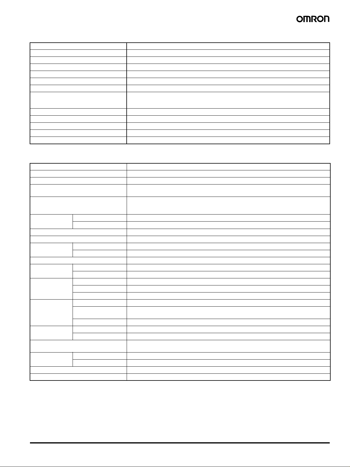
Ordering Information
■ Digital Controllers
Programmable Digital Controllers
Size Control type Control mode Outputs
× 96
96
mm
Basic control
(1 loop)
2-loop control 2-loop standard control
4-loop control 4-loop standard control
Control valve
control
(1 loop)
Standard control
Heating and cooling control
Single-loop heating and cooling control
Single-loop cascade control
Single-loop control with remote SP
Single-loop proportional control
2-loop heating and cooling control
(See note 4.)
Single-loop position-proportional control Relay outputs
(control/transfer)
2 (pulse + pulse/current)
2 (current + current) E5AR-TC4B
2 (pulse + pulse/current)
2 (current + current) E5AR-TC43B-FLK
2 (pulse + pulse/current)
2 (current + current) E5AR-TCE3MB-FLK
4 (pulse + pulse/current + 2 current)
2 (pulse + pulse/current)
2 (current + current) E5AR-TC43DW-FLK
4 (2 pulse + pulse/2
current)
4 (4 current) 10 (See
4 (2 pulse + pulse/2
current)
(1 open, 1 closed)
Relay outputs
(1 open, 1 closed) +
1 current
Optional functions Model
Auxiliary
outputs
(SUB)
4 2 None E5AR-TQ4B
10 (See
note 3.)
4 4 RS-485 E5AR-TQ43DW-FLK
10 (See
note 3.)
note 3.)
4 4 None E5AR-TPR4DF
10 (See
note 3.)
Event
inputs
10 E5AR-TQE3MB-FLK
8 E5AR-TQQE3MW-
8 RS-485 E5AR-TCCE3MWW-
8 RS-485 E5AR-TPRQE3MF-
Serial
communi-
cations
RS-485 E5AR-TQ43B-FLK
(See note 2.)
(See note 2.)
(See note 2.)
(See note 2.)
E5AR-TQCE3MB-FLK
(See note 2.)
(See note 2.)
FLK
FLK
E5AR-TQQE3MWWFLK (See note 2.)
FLK
Note 1: Specify the power supply specifications when ordering. Model numbers for 100 to 240 VAC are different from those for 24 VAC/VDC.
2: These models are for 100 to 240 VAC only.
3: The outputs are transistor output.
4: Only for coordinated operation. (A separate program cannot be set for each channel.)
Inspection Results
If an inspection report is required, it can be ordered at the same time
as the Digital Controller using the following model number.
Inspection Report (Order Separately)
Model
E5AR-K
■ Accessories (Order Separately)
Terminal Cover
Descriptions Model
Terminal Cover for E5AR E53-COV14
Unit Label Sheet
Model
Y92S-L1
Rubber Packing
Model
Y92S-P4
Note: The Rubber Packing is provided with the Digital Controller.
Programmable Digital Controller E5AR-T 5
Page 6

Specifications
■ Ratings
Supply voltage
(See note 2.)
CE marking 100 to 240 VAC, 50/60 Hz 24 VAC, 50/60 Hz; 24 VDC
UL certification 100 to 120 VAC, 50/60 Hz 24 VAC, 50/60 Hz; 24 VDC
Operating voltage range 85% to 110% of rated supply voltage
Power consumption 22 VA max. (with maximum load) 15 VA/10 W max. (with maximum load)
Sensor input (See note 3.) Thermocouple: K, J, T, E, L, U, N, R, S, B, W
Platinum resistance thermometer: Pt100
Current input: 4 to 20 mA DC, 0 to 20 mA DC (including remote SP input)
Voltage input: 1 to 5 VDC, 0 to 5 VDC, 0 to 10 VDC (including remote SP input)
(Input impedance: 150
Ω for current input, approx. 1 MΩ for voltage input)
Control output Voltage (pulse) output 12 VDC, 40 mA max. with short-circuit protection circuit (E5AR-TQQE3MW-FLK: 21 mA max.)
Current output 0 to 20 mA DC, 4 to 20 mA DC; load: 500
Relay output Position-proportional control type (open, closed)
Auxiliary output Relay Output
Potentiometer input 100
(Resolution: Approx. 54,000 for 0 to 20 mA DC; Approx. 43,000 for 4 to 20 mA DC)
N.O., 250 VAC, 1 A (including inrush current)
N.O., 250 VAC, 1 A (resistive load)
Transistor Output
Maximum load voltage: 30 VDC; Maximum load current: 50 mA; Residual voltage: 1.5 V max.; Leakage current: 0.4 mA max.
Ω to 2.5 kΩ
Ω max. (including transfer output)
Event input Contact Input ON: 1 kΩ max.; OFF: 100 kΩ min.
No-contact Input ON: Residual voltage of 1.5 V max.; OFF: Leakage current of 0.1 mA max.
Short-circuit: Approx. 4 mA
Remote SP input Refer to the information on sensor input.
Transfer output Refer to the information on control output.
Control method 2-PID or ON/OFF control
Setting method Digital setting using front panel keys or setting using serial communications
Indication method 7-segment digital display and single-lighting indicator
Character Height
PV display: 12.8 mm; SV display: 7.7 mm; MV display: 7.7 mm
Other functions Depends on model.
Ambient operating temperature
−10 to 55°C (with no icing or condensation)
For 3 years of assured use:
−10 to 50°C (with no icing or condensation)
Ambient operating humidity 25% to 85%
Storage temperature
−25 to 65°C (with no icing or condensation)
Note 1: Do not use an inverter output as the power supply. (Refer to page 25.)
2: The supply voltage (i.e., 100 to 240 VAC or 24 VAC/VDC) depends on the model. Be sure to specify the required type when ordering.
3: The Controller is equipped with multiple sensor input. Temperature input or analog input can be selected with the input type setting switch. There is basic
insulation between power supply and input terminals, power supply and output terminals, and input and output terminals.
■ Input Ranges
Platinum Resistance Thermometer, Thermocouple, Current, or Voltage Input
Input type
Name
Temperature
range (
°C)
Setting 0 1 2345678910111213141516171819
Minimum
setting unit
(SP and alarm)
Input type
setting switch
Note: The shaded area indicates the setting status at the time of purchase.
6 Programmable Digital Controller E5AR-T
Platinum
resistance
thermometer
Thermocouple Current Voltage
Pt100 K J T E L U N R S B W
2300
1800
1300
850.0 85 0.0 850. 0
900
800
700
600
400
200
100
0
−100
−200
−200.0 −150.00 −200.0 −200.0 −200.0 −200.0
0.1°C
1300.0 1300.0
500.0 60 0.0
150.00
−20.0 −100.0 −20.0 −100.0
0.01
°C
400.0 400. 0 400.0
0.0 0.0 0.0 0.0
0.1
TC.PT
Set to TC.PT. Set to ANALOG
IN1
TYPE
ANALOG
°C
1700.0 1700.0 1800.0
100.0
W/Re
()
5-26
2300.0
mA V
20 to 420 to
0
5 to 1 5 to 0
(Depends on scaling and number
of decimal places.)
TC.PT
IN1
TYPE
ANALOG
10 to
0
Page 7

■ Characteristics
Indication accuracy Thermocouple input with cold junction compensation: (±0.1% of PV or ±1°C, whichever is greater) ±1 digit max. (See note 1.)
Control mode Standard control (heating or cooling control), heating/cooling control, standard control with remote SP (2-input models only), heating/
Influence of temperature Thermocouple input (R, S, B, W):
Influence of voltage
Control period 0.2 to 99.0 s (in units of 0.1 s) for time-proportioning control output
Proportional band (P) 0.00% to 999.99% FS (in units of 0.01% FS)
Integral time (I) 0.0 to 3,999.9 s (in units of 0.1 s)
Derivative time (D) 0.0 to 3,999.9 s (in units of 0.1 s)
Hysteresis 0.01% to 99.99% FS (in units of 0.01% FS)
Manual reset value 0.0% to 100.0% (in units of 0.1% FS)
Alarm setting range −19,999 to 99,999 EU (See note 3.)
Input sampling period 50 ms
Insulation resistance 20 MΩ min. (at 500 VDC)
Dielectric strength 2,000 VAC, 50/60 Hz for 1 min (between charged terminals of different polarities)
Vibration resistance (malfunction)
Shock resistance (malfunction)
Inrush current 100 to 240-VAC models: 50 A max.
Weight Controller only: Approx. 450 g; Mounting bracket: Approx. 60 g; Terminal cover: Approx. 30 g
Degree of protection Front panel: NEMA4X for indoor use (equivalent to IP66); Rear case: IP20; Terminals: IP00
Memory protection Non-volatile memory (number of writes: 100,000)
Applicable standards UL 61010C-1, CSA C22.2 No. 1010-1
EMC EMI: EN61326
Note 1: K-, T-, or N-type thermocouple at −100°C max.: ±2°C ±1 digit max.
U- or L-type thermocouple:
B-type thermocouple at 400
R- or S-type thermocouple at 200
W-type thermocouple: (
2: U- or L-type thermocouple:
R- or S-type thermocouple at 200
3: “EU” (Engineering Unit) represents the unit after scaling. If a temperature sensor is used, it is either
Thermocouple input without cold junction compensation: (±0.1% FS or ±1°C, whichever is smaller) ±1 digit (See note 2.)
Analog input: ±0.1% FS ±1 digit max.
Platinum resistance thermometer input: (±0.1% of PV or ±0.5°C, whichever is greater) ±1 digit max.
Position-proportional potentiometer input: ±5% FS ±1 digit max.
cooling control with remote SP (2-input models only), cascade standard control (2-input models only), cascade heating/cooling control
(2-input models only), proportional control (2-input models only), position-propor tional control (control-valve control models only)
(±1% of PV or ±10°C, whichever is greater) ±1 digit max.
Other thermocouple input:
( ±1% of PV or ±4°C, whichever is greater) ±1 digit max.
*K thermocouple at -100°C max.: ±10°C max.
Platinum resistance thermometer:
(±1% of PV or ±2°C, whichever is greater) ±1 digit max.
Analog input: (±1%FS) ±1 digit max.
(The decimal point position depends on the input type and the decimal point position setting.)
10 to 55 Hz, 20 m/s
2
100 m/s
, 3 times each in X, Y, and Z directions
24 VAC/VDC models: 30 A max.
(Power supply voltage: 100 to 120 VAC): Pollution degree 2/Overvoltage category 2
EN 61010-1 (IEC 61010-1) (Power supply voltage: 100 to 240 VAC): Pollution degree 2/Overvoltage category 2
Radiated Interference Electromagnetic Field Strength: EN55011 Group 1 Class A
Noise Terminal Voltage: EN55011 Group 1 Class A
EMS: EN61326
ESD Immunity: EN61000-4-2: 4 kV contact discharge (level 2)
Electromagnetic Immunity: EN61000-4-3: 10 V/m (amplitude-modulated, 80 MHz to 1 GHz, 1.4 GHz to 2 GHz) (level 3)
Burst Noise Immunity: EN61000-4-4: 2 kV power line (level 3)
Conducted Disturbance Immunity: EN61000-4-6: 3 V (0.15 to 80 MHz) (level 3)
Surge Immunity: EN61000-4-5: 1 kV line to line (power line, output line (relay output)) (level 2)
Power Frequency Magnetic Field Immunity: EN61000-4-8: 30 A/m (50 Hz) continuous field
Voltage Dip/Interrupting Immunity: EN61000-4-11: 0.5 cycle, 100% (rated voltage)
±2°C ±1 digit max.
°C max.: No accuracy specification.
±0.3% of PV or ±3°C, whichever is greater) ±1 digit max.
°C max.: ±3°C ±1 digit max.
±1°C ±1 digit
°C max.: ±1.5°C ±1 digit
2
for 10 min each in X, Y, and Z directions
8 kV air discharge (level 3)
2 kV output line (relay output) (level 4)
1 kV measurement line, I/O signal line (level 4)
1 kV communications line (level 3)
2 kV line to ground (power line, output line (relay output)) (level 3)
°C or °F.
Programmable Digital Controller E5AR-T 7
Page 8

■ Communications Specifications
Transmission path connection Multiple points
Communications method RS-485 (two-wire, half duplex)
Synchronization method Start-stop synchronization
Baud rate 9,600, 19,200, or 38,400 bps
Transmission code ASCII
Data bit length 7 or 8 bits
Stop bit length 1 or 2 bits
Error detection Vertical parity (none, even, odd)
Flow control None
Interface RS-485
Retry function None
Communications buffer 217 bytes
Communications response send wait time 0 to 99 ms, Default: 20 ms
Block check character (BCC): CompoWay/F
CRC-16: Modbus
■ Program Control Functions
Number of programs (patterns) 32 (with 8 segments/program)
Number of segments (steps) 32 (with 8 programs)
Maximum number of segments 256
Segment setting method Time setting (Segment set with set point and time.)
Segment times 0 h 0 min to 99 h 59 min
Alarm group number specifications
Reset operation Select either stopping control or fixed SP operation.
Startup operation Select continuing, resetting, manual operation, run mode, or ramp back operation.
PID groups Number of groups 8
Alarm SP function Select from ramp SP and target SP.
Program status
control
Wait operation Wait method Select from waiting at segment ends and always waiting.
Time signals Number of outputs 6
Segment outputs Number of outputs 10
Program status output Program end output (pulse width can be set)
Program startup
operation
Operation end operation Select from resetting, continuing control at final set point, and fixed SP control.
Number of event inputs 10 max.
Number of groups 4
Setting method Set separately for each program.
Setting method Set separately for each program (automatic PID group selection also supported).
Segment operation Advance, hold, and back
Program operation Program repetitions and program links
Wait width setting Wait width upper limit and lower limit set separately for each program.
Setting method ON/OFF setting for each segment
Number of ON/OFF
operations
Setting method Set separately for each program.
Setting method ON/OFF set for each segment.
PV start Select from segment 1 set point, slope-priority PV start, and time-priority PV start.
Standby Standby
Gradient setting (Segment set with set point, gradient, and time.)
0 min 0 s to 99 min 59 s
0 min 00.0 s to 99 min 59.9 s
3 each per output
Segment number output
8 Programmable Digital Controller E5AR-T
Page 9

Wiring Terminals
■ E5AR-T (Programmable Type)
E5AR-TQ4B E5AR-TC4B
24 VAC/DC 100 to 240 VAC
−
+
+
−
Input power supply
depends on model.
100 to 240 VAC or 24
VAC/DC (no polarity)
!
OUT2
Voltage output 12 V
40 mA
OUT1
Voltage output 12 V
40 mA or
Current output
4 to 20 mA DC, 500 Ω max.
0 to 20 mA DC, 500 Ω max.
(Switched by output type setting.)
BEDCA
1
2
3
4
5
6
1
Auxiliary output
(Relay output)
B
1
2
3
4
5
6
COM
SUB1
SUB2
COM
SUB3
SUB4
2
3
4
5
6
KJIHGF
1
2
+
3
−
4
+
5
−
6
F
Event input
EV1
EV2
COM
+
−
+
VI
(Voltage)
−
+
TCPT
(Thermocouple)
−
(Current)
(Resistance temperature input sensor)
1
2
3
4
5
6
K
24 VAC/DC
−
+
+
−
Input power supply
depends on model.
100 to 240 VAC or 24
VAC/DC (no polarity)
OUT2
Current output
4 to 20 mA DC, 500 Ω max.
0 to 20 mA DC, 500 Ω max.
(Switched by output
type setting.)
OUT1
Current output
4 to 20 mA DC, 500 Ω max.
0 to 20 mA DC, 500 Ω max.
(Switched by output
type setting.)
100 to 240 VAC
!
BEDCA
1
2
3
4
5
6
1
2
Auxiliary output
(Relay output)
B
1
2
3
4
5
6
COM
SUB1
SUB2
COM
SUB3
SUB4
3
4
5
6
KJIHGF
1
2
+
3
−
4
+
5
−
6
F
Event input
EV1
EV2
COM
+
−
+
(Voltage)
−
+
TCPTVI
(Thermocouple)
−
(Current)
(Resistance temperature input sensor)
1
2
3
4
5
6
K
E5AR-TQ43B-FLK E5AR-TC43B-FLK
B(+)
RS-485
OUT2
Voltage output 12 V 40 mA
OUT1
Voltage output 12 V
40 mA or
Current output
4 to 20 mA DC, 500 Ω max.
0 to 20 mA DC, 500 Ω max.
(Switched by output type setting.)
A(−)
100 to 240 VAC
!
+
1
−
2
+
3
−
4
+
5
−
6
F
Auxiliary output
(Relay output)
BEDCA
1
2
3
4
5
6
B
COM
1
SUB1
2
SUB2
3
COM
4
SUB3
5
SUB4
6
1
2
3
4
5
6
KJIHGF
Event input
EV1
EV2
COM
+
−
−
++
(Voltage)
(Current)
(Resistance temperature input sensor)
−
TCPTVI
(Thermocouple)
1
2
3
4
5
6
K
100 to 240 VAC
!
OUT2
Current output
4 to 20 mA DC, 500 Ω max.
0 to 20 mA DC, 500 Ω max.
(Switched by output
type setting.)
OUT1
Current output
4 to 20 mA DC, 500 Ω max.
0 to 20 mA DC, 500 Ω max.
(Switched by output
type setting.)
RS-485
B(+)
A(−)
1
2
3
4
5
6
1
2
3
4
5
6
+
−
The power supply voltage must be 100 to 240 VAC or 24 VAC/DC for the E5AR-T to comply with CE
Note
marking requirements.
The power supply voltage must be 100 to 120 VAC or 24 VAC/DC for the E5AR-T to comply with UL
requirements.
BEDCA
Auxiliary output
(Relay output)
B
1
2
3
4
5
6
COM
SUB1
SUB2
COM
SUB3
SUB4
KJIHGF
1
2
+
3
−
4
+
5
−
6
F
Event input
EV1
EV2
COM
+
−
+
VI
(Voltage)
−
+
TCPT
(Thermocouple)
−
(Current)
(Resistance temperature input sensor)
1
2
3
4
5
6
K
Programmable Digital Controller E5AR-T 9
Page 10

E5AR-TQE3MB-FLK E5AR-TCE3MB-FLK
100 to 240 VAC
RS-485
OUT2
Voltage output 12 V 40 mA
OUT1
Voltage output 12 V
40 mA or
Current output
4 to 20 mA DC, 500 Ω max.
0 to 20 mA DC, 500 Ω max.
(Switched by output type setting.)
1
!
2
3
4
5
6
1
2
3
4
5
6
+
B(+)
1
−
A(−)
2
+
3
−
4
+
5
−
6
F
E5AR-TQCE3MB-FLK
24 VAC/DC
OUT2
Voltage output 12 V
40 mA
OUT1
Voltage output 12 V
40 mA or
Current output
4 to 20 mA DC, 500 Ω max.
0 to 20 mA DC, 500 Ω max.
(Switched by output type setting.)
100 to 240 VAC
-
+
+
Input power supply
depends on model.
100 to 240 VAC or 24
VAC/DC (no polarity)
RS-485
OUT4
Current output
4 to 20 mA DC, 500 Ω max.
0 to 20 mA DC, 500 Ω max.
(Switched by output
type setting.)
OUT3
Current output
4 to 20 mA DC, 500 Ω max.
0 to 20 mA DC, 500 Ω max.
(Switched by output type setting.)
!
-
+
B(+)
1
−
A(−)
2
+
3
−
4
+
5
−
6
F
Auxiliary output
(Transistor output)
BEDCA
1
COM
SUB1(B), SUB6(C)
SUB2(B), SUB7(C)
SUB3(B), SUB8(C)
SUB4(B), SUB9(C)
SUB5(B), SUB10(C)
EV3(E), EV7(D)
EV4(E), EV8(D)
EV5(E), EV9(D)
KJIHGF
EV6(E), EV10(D)
COM
Event input
EV1
EV2
COM
+
−
−
++
VI
(Thermocouple)
(Voltage)
(Current)
(Resistance temperature input sensor)
BEDCA
2
3
4
5
6
1
2
3
4
5
6
1
2
+
3
−
+
4
+
5
−
−
6
G
(Current)
(Resistance temperature input sensor)
−
+
+
+
+
+
Event input
1
2
3
4
−
5
6
TCPT
K
Auxiliary output
(Transistor output)
COM
SUB1(B), SUB6(C)
SUB2(B), SUB7(C)
SUB3(B), SUB8(C)
SUB4(B), SUB9(C)
SUB5(B), SUB10(C)
Event input
EV3(E), EV7(D)
EV4(E), EV8(D)
EV5(E), EV9(D)
EV6(E), EV10(D)
COM
KJIHGF
Event input
−
++
(Voltage)
EV1
EV2
COM
1
2
3
4
−
5
6
TCPTVI
K
(Thermocouple)
Auxiliary output
C
B
1
2
3
100 to 240 VAC
!
4
5
6
E
D
1
2
3
4
BEDCA
1
2
3
4
5
6
1
2
3
4
5
6
5
6
OUT2
Current output
4 to 20 mA DC, 500 Ω max.
0 to 20 mA DC, 500 Ω max.
(Switched by output
type setting.)
OUT1
Current output
4 to 20 mA DC, 500 Ω max.
0 to 20 mA DC, 500 Ω max.
(Switched by output type setting.)
C
B
-
1
+
2
+
3
+
4
+
5
+
6
E
D
1
RS-485
B(+)
A(−)
+
1
−
2
+
3
−
4
+
5
−
6
F
(Transistor output)
COM
SUB1(B), SUB6(C)
SUB2(B), SUB7(C)
SUB3(B), SUB8(C)
SUB4(B), SUB9(C)
SUB5(B), SUB10(C)
Event input
EV3(E),EV7(D)
EV4(E),EV8(D)
EV5(E),EV9(D)
KJIHGF
EV6(E),EV10(D)
COM
Event input
EV1
EV2
COM
+
−
−
++
PTIV
(Voltage)
(Current)
(Resistance temperature input sensor)
1
2
3
4
−
5
6
TC
K
(Thermocouple)
B
C
−
1
+
2
+
3
+
4
+
5
+
6
E
D
1
2
3
4
5
6
2
3
4
5
6
The power supply voltage must be 100 to 240 VAC or 24 VAC/DC for the E5AR-T to comply with CE
Note
marking requirements.
The power supply voltage must be 100 to 120 VAC or 24 VAC/DC for the E5AR-T to comply with UL
requirements.
10 Programmable Digital Controller E5AR-T
Page 11

E5AR-TQ43DW-FLK (2-loop Control) E5AR-TC43DW-FLK (2-loop Control)
Auxiliary output
(Relay output)
B
COM
100 to 240 VAC
B(+)
RS-485
OUT2
Voltage output 12 V 40 mA
OUT1
Voltage output 12 V
40 mA or
Current output
4 to 20 mA DC, 500 Ω max.
0 to 20 mA DC, 500 Ω max.
(Switched by output type setting.)
A(−)
BEDCA
1
!
2
3
4
5
+
6
1
1
−
2
2
+
3
3
−
4
4
+
5
5
6
−
6
F
Input 2
Input 1
(Current)
(Resistance temperature input sensor)
1
2
3
4
5
6
Event input
EV3
EV4
EV5
KJIHGF
EV6
COM
+
−
−
+
−
−
+
+
VI
TCPT
−
−
++
VI
TCPT
(Thermocouple)
(Voltage)
SUB1
SUB2
COM
SUB3
SUB4
1
2
3
4
5
6
K
E
1
2
3
4
5
6
OUT2
Current output
4 to 20 mA DC, 500 Ω max.
0 to 20 mA DC, 500 Ω max.
(Switched by output
type setting.)
OUT1
Current output
4 to 20 mA DC, 500 Ω max.
0 to 20 mA DC, 500 Ω max.
(Switched by output type setting.)
RS-485
100 to 240 VAC
+
B(+)
−
A(−)
+
−
+
−
BECA
1
!
2
3
4
5
6
1
1
2
2
3
3
4
4
5
5
6
6
F
D
KJIHGF
+
−
−
Input 2
+
+
I
V
−
−
Input 1
+
VI
(Voltage)
(Current)
(Resistance temperature input sensor)
E5AR-TQQE3MW-FLK (2-loop Control)
Auxiliary output
24 VAC/DC 100 to 240 VAC
−
+
+
−
Input power supply
depends on model.
100 to 240 VAC or 24
VAC/DC (no polarity)
B(+)
RS-485
OUT2
Voltage output 12 V
40 mA
OUT1
Voltage output 12 V
40 mA or
Current output
4 to 20 mA DC, 500 Ω max.
0 to 20 mA DC, 500 Ω max.
(Switched by output type setting.)
OUT4
OUT3
A(−)
Voltage output 12 V
40 mA
Voltage output 12 V
40 mA or
Current output
4 to 20 mA DC, 500 Ω max.
0 to 20 mA DC, 500 Ω max.
(Switched by output type setting.)
(Transistor output)
!
+
1
−
2
+
3
−
4
+
5
−
6
F
BECA
1
2
3
4
5
6
1
2
3
4
5
6
1
2
Input 2
+
3
−
4
+
5
Input 1
−
6
G
COM
D
SUB1(B), SUB6(C)
SUB2(B), SUB7(C)
SUB3(B), SUB8(C)
SUB4(B), SUB9(C)
SUB5(B), SUB10(C)
EV3(E), EV7(D)
EV4(E), EV8(D)
EV5(E), EV9(D)
KJIHGF
EV6(E), EV10(D)
COM
+
−
−
+
+
VII
−
−
++
(Voltage)
(Current)
(Resistance temperature input sensor)
PT
PT
1
−
2
3
+
TC
4
−
5
6
TCV
K
(Thermocouple)
Event input
C
B
−
1
+
2
+
3
+
4
+
5
+
6
ED
1
2
3
4
5
6
Auxiliary output
(Relay output)
B
1
2
3
4
5
6
Event input
EV3
EV4
EV5
EV6
COM
−
+
TCPT
−
+
TCPT
(Thermocouple)
COM
SUB1
SUB2
COM
SUB3
SUB4
E
1
2
3
4
5
6
1
2
3
4
5
6
K
Note
The power supply voltage must be 100 to 240 VAC or 24 VAC/DC for the E5AR-T to comply with CE
marking requirements.
The power supply voltage must be 100 to 120 VAC or 24 VAC/DC for the E5AR-T to comply with UL
requirements.
Programmable Digital Controller E5AR-T 11
Page 12

E5AR-TCCE3MWW-FLK (4-loop Control) E5AR-TQQE3MWW-FLK (4-loop Control)
Auxiliary output
24 VAC/DC
OUT2
Current output
4 to 20 mA DC, 500 Ω max.
0 to 20 mA DC, 500 Ω max.
(Switched by output
type setting.)
OUT1
Current output
4 to 20 mA DC, 500 Ω max.
0 to 20 mA DC, 500 Ω max.
(Switched by output type setting.)
OUT4
Current output
4 to 20 mA DC, 500 Ω max.
0 to 20 mA DC, 500 Ω max.
(Switched by output
type setting.)
OUT3
Current output
4 to 20 mA DC, 500 Ω max.
0 to 20 mA DC, 500 Ω max.
(Switched by output type setting.)
100 to 240 VAC
−
+
+
−
Input power supply
depends on model.
100 to 240 VAC or 24
VAC/DC (no polarity)
B(+)
RS-485
A(−)
(Transistor output)
COM
SUB1(B), SUB6(C)
D
!
+
1
−
2
+
3
−
4
+
5
−
6
F
1
2
+
3
−
4
+
5
−
6
G
BECA
1
2
3
4
5
6
1
2
3
4
5
6
Input 2(K)
Input 4(J)
Input 1(K)
Input 3(J)
(Current)
(Resistance temperature input sensor)
+
−
+
I
−
I
(Voltage)
KJIHGF
−
+
V
−
+
V
SUB2(B), SUB7(C)
SUB3(B), SUB8(C)
SUB4(B), SUB9(C)
SUB5(B), SUB10(C)
EV3(E), EV7(D)
EV4(E), EV8(D)
EV5(E), EV9(D)
EV6(E), EV10(D)
COM
−
+
TCPT
−
+
TCPT
(Thermocouple)
Event input
1
2
3
4
5
6
J, K
C
B
−
1
+
2
+
3
+
4
+
5
+
6
E
D
1
2
3
4
5
6
OUT2
Voltage output 12 V 21 mA
OUT1
Voltage output 12 V
21 mA or
Current output
4 to 20 mA DC, 500 Ω max.
0 to 20 mA DC, 500 Ω max.
(Switched by output type setting.)
OUT4
Voltage output 12 V 21 mA
OUT3
Voltage output 12 V
21 mA or
Current output
100 to 240 VAC
!
+
B(+)
RS-485
4 to 20 mA DC, 500 Ω max.
0 to 20 mA DC, 500 Ω max.
(Switched by output type setting.)
1
−
A(−)
2
+
3
−
4
+
5
−
6
F
+
−
+
−
1
2
3
4
5
6
1
2
3
4
5
6
1
2
3
4
5
6
G VI
E5AR-TPR4DF E5AR-TPRQE3MF-FLK
Auxiliary output
(Relay output)
100 to 240 VAC
24 VAC/DC
−
+
+
−
Input power supply
depends on model.
100 to 240 VAC or 24
VAC/DC (no polarity)
OUT2
OUT1
!
1
2
3
4
5
6
1
2
3
4
5
6
1
Relay output
2
250 VAC 1 A
3
4
5
6
F
BEDCA
Closed
Open
Potentiometer
+
−
I
(Current)
(Resistance temperature input sensor)
B
1
2
3
4
5
6
Event input
EV3
EV4
EV5
EV6
KJIHGF
COM
O
1
W
2
C
3
PT
4
−
5
6
TC
K
(Thermocouple)
−
++
V
(Voltage)
COM
SUB1
SUB2
COM
SUB3
SUB4
E
1
2
3
4
5
6
24 VAC/DC
OUT4
Voltage output 12 V
40 mA
OUT3
Voltage output 12 V
40 mA or
Current output
4 to 20 mA DC,
500 Ω max.
0 to 20 mA DC, 500 Ω max.
(Switched by output type setting.)
100 to 240 VAC
−
+
+
−
Input power supply
depends on model.
100 to 240 VAC or 24
VAC/DC (no polarity)
+
−
+
−
B(+)
RS-485
A(−)
OUT2
OUT1
1
!
2
3
4
5
1
6
1
2
2
3
3
4
4
5
6
5
G
6
+
1
−
Relay output
2
250 VAC 1 A
3
4
5
6
F
BECA
Input 2(K)
Input 4(J)
Input 1(K)
Input 3(J)
SUB2(B), SUB7(C)
SUB3(B), SUB8(C)
SUB4(B), SUB9(C)
SUB5(B), SUB10(C)
EV3(E), EV7(D)
EV4(E), EV8(D)
EV5(E), EV9(D)
KJIHGF
EV6(E), EV10(D)
COM
+
−
−
+
+
I
V
−
−
+
(Voltage)
(Current)
(Resistance temperature input sensor)
COM
SUB1(B), SUB6(C)
D
BEDCA
Potentiometer
+
Closed
Open
−
−
+
I
(Current)
(Resistance temperature input sensor)
Auxiliary output
(Transistor output)
Event input
−
+
TCPT
−
+
TCPT
(Thermocouple)
Auxiliary output
(Transistor output)
COM
SUB1(B), SUB6(C)
SUB2(B), SUB7(C)
SUB3(B), SUB8(C)
SUB4(B), SUB9(C)
SUB5(B), SUB10(C)
EV3(E), EV7(D)
EV4(E), EV8(D)
EV5(E), EV9(D)
EV6(E), EV10(D)
COM
KJIHGF
−
+
PTV
TC
(Thermocouple)
(Voltage)
C
B
−
1
+
2
+
3
+
4
+
5
+
6
E
D
1
2
3
4
5
6
1
2
3
4
5
6
J, K
BEDC
−
1
+
2
+
3
+
4
+
5
+
6
Event input
1
2
3
4
5
6
O
1
W
2
C
3
4
5
6
K
The power supply voltage must be 100 to 240 VAC or 24 VAC/DC for the E5AR-T to comply with CE
Note
marking requirements.
The power supply voltage must be 100 to 120 VAC or 24 VAC/DC for the E5AR-T to comply with UL
requirements.
12 Programmable Digital Controller E5AR-T
Page 13

Nomenclature
E5AR-T
Operation
Indicators
Channel
Indicator
SUB1 SUB2 SUB3 SUB4 WAIT FSP
PV
Rear
No. 1 Display
Bar Graph
Program Status
Indicators
Function Key 1/
Run/Reset Key
CMW MANU
OUT1
PF1
RUN/RST
Function Key 2
OUT2 OUT3 OUT4 RST RSP HOLD
PF2
Level Key
Mode Key Down Key Up Key
Dimensions
Note: All units are in millimeters unless otherwise indicated.
96
SUB1 SUB2 SUB3 SUB4 WAIT FSP
96
CMW MANU
OUT2 OUT3 OUT4 RST RSP HOLD
OUT1
PF2
PF1
RUN/RST
SV
PRG.
SEG
No. 2 Display
No. 3 Display
11.5 95
3
PV
SV
PRG.
SEG
110
2
111
91 × 91
120 min.
Panel Cutouts
+0.8
92
0
Crimp terminal size: M3
110 min.
+0.8
92
0
Terminal cover (E53-COV14: order separately)
• Recommended panel thickness is 1 to 8 mm.
• Group mounting is not possible. (Maintain the specified
mounting space between Controllers.)
• When two or more Controllers are mounted, make sure
that the surrounding temperature does not exceed the
allowable operating temperature specified in the specifications.
Programmable Digital Controller E5AR-T 13
Page 14

■ Accessories (Order Separately)
Terminal Cover
E53-COV14 (for E5AR)
95
28.5
10.1
Unit Label Sheet
Y92S-L1
11.8
95
Rubber Packing
Y92S-P4 (for DIN96 × 96)
4.8
Order the Rubber Packing separately if it becomes lost or damaged. (Refer to page 5.)
(Deterioration, shrinking, or hardening of the rubber packing may occur depending on the operating
environment. Therefore, periodic replacement is recommended to ensure the level of waterproofing
specified in NEMA4. The time for periodic replacement depends on the operating environment. Be
sure to confirm this point at your site. Consider one year a rough standard. OMRON shall not be liable for the level of water resistance if the customer does not perform periodic replacement.)
ALL DIMENSIONS SHOWN ARE IN MILLIMETERS.
To convert millimeters into inches, multiply by 0.03937. To convert grams into ounces, multiply by 0.03527.
14 Programmable Digital Controller E5AR-T
Page 15

Programmable Digital Controller
E5ER-T
A new 48 x 96-mm High-speed, Highprecision Digital Controller that is
Programmable!
• Create up to 32 programs with up to 256 segments total.
•0.01°C High resolution for Pt input.
• High-speed sampling at 50 ms.
• Settings easily made from a computer using the CX-Thermo.
• RoHS compliance for world-wide application.
Refer to the “Precautions” on pages 24 and 25.
Model Number Structure
■ Model Number Legend
E5ER-T@@@@@@@@-@@@
2345 96781
1. Control method
Blank:Standard or heating/cooling control
P: Position proportional control
2. Output 1
R: NO relay output + NO relay output
Q: Pulse output/current output + pulse output
C: Current output + current output
3. Output 2
R: NO relay output + NO relay output
Q: Pulse output/current output + pulse output
C: Current output + current output
4. Auxiliary Outputs
Blank:None
4: NO relay output + NO relay output
T: 2 transistor outputs
5. Communications
Blank: None
3: RS-485 communications
6. Optional Function
Blank: None
D: 4 event inputs
7. Input 1
B: Multi-input and 2 event inputs
F: Multi-input and FB (Potentiometer input)
W: Multi-input and multi-input
8. Input 2
Blank: None
W: Multi-input and multi-input
9. Other
FLK: CompoWay/F communications
(3 digits):(Modification type)
Note: Be sure to read the precautions for correct use and other precautions in the following user's manual before using the Digital
Controller.
E5AR/ER Programmable Digital Controller User's Manual (Cat. No. Z182)
A PDF version of the user's manual can be downloaded from the following web site:
OMRON Industrial Web http://www.fa.omron.co.jp/
Programmable Digital Controller E5ER-T 15
Page 16

Ordering Information
■ Digital Controllers
Programmable Digital Controllers
Size Control type Control mode Outputs (control/
× 96
48
mm
Note 1: Specify the power supply specifications when ordering. Model numbers for 100 to 240 VAC are different from those for 24 VAC/VDC.
Basic control
(1 loop)
2-loop control 2-loop standard control
Control valve
control
(1 loop)
2: The outputs are transistor output.
Standard control
Heating and cooling control
Single-loop heating and cooling control
Single-loop cascade control
Single-loop control with remote SP
Single-loop proportional control
Single-loop position-proportional control Relay outputs
transfer)
2 (pulse + pulse/current)
2 (current + current) E5ER-TC4B
2 (pulse + pulse/current)
2 (pulse + pulse/current)
2 (current + current) E5ER-TCT3DW-FLK
(1 open, 1 closed)2 (See Note
Relay outputs
(1 open, 1 closed) +
1 current
Optional functions Model
Auxiliary
outputs
(SUB)
4 2 None E5ER-TQ4B
2
(See Note
2.)
2.)
4 None RS-485 E5ER-TPRQ43F-
Event
inputs
4 RS-485 E5ER-TQT3DW-FLK
4 None E5ER-TPRTDF
Serial
commu-
nications
RS-485 E5ER-TQC43B-FLK
FLK
Inspection Results
If an inspection report is required, it can be ordered at the same time
as the Digital Controller using the following model number.
Inspection Report (Order Separately)
Model
E5ER-K
■ Accessories (Order Separately)
Terminal Cover
Descriptions Model
Terminal Cover for E5ER E53-COV15
Rubber Packing
Model
Y92S-P5
Note: The Rubber Packing is provided with the Digital Controller.
16 Programmable Digital Controller E5ER-T
Page 17

Specifications
■ Ratings
Supply voltage
(See note 2.)
CE marking 100 to 240 VAC, 50/60 Hz 24 VAC, 50/60 Hz; 24 VDC
UL certification 100 to 120 VAC, 50/60 Hz 24 VAC, 50/60 Hz; 24 VDC
Operating voltage range 85% to 110% of rated supply voltage
Power consumption 17 VA max. (with maximum load) 11 VA/7 W max. (with maximum load)
Sensor input (See note 3.) Thermocouple: K, J, T, E, L, U, N, R, S, B, W
Platinum resistance thermometer: Pt100
Current input: 4 to 20 mA DC, 0 to 20 mA DC (including remote SP input)
Voltage input: 1 to 5 VDC, 0 to 5 VDC, 0 to 10 VDC (including remote SP input)
(Input impedance: 150
Ω for current input, approx. 1 MΩ for voltage input)
Control output Voltage (pulse) output 12 VDC, 40 mA max. with short-circuit protection circuit
Current output 0 to 20 mA DC, 4 to 20 mA DC; load: 500
Relay output Position-proportional control type (open, closed)
Auxiliary output Relay Output
Potentiometer input 100
(Resolution: Approx. 54,000 for 0 to 20 mA DC; Approx. 43,000 for 4 to 20 mA DC)
N.O., 250 VAC, 1 A (including inrush current)
N.O., 250 VAC, 1 A (resistive load)
Transistor Output
Maximum load voltage: 30 VDC; Maximum load current: 50 mA; Residual voltage: 1.5 V max.; Leakage current: 0.4 mA max.
Ω to 2.5 kΩ
Ω max. (including transfer output)
Event input Contact Input ON: 1 kΩ max.; OFF: 100 kΩ min.
No-contact Input ON: Residual voltage of 1.5 V max.; OFF: Leakage current of 0.1 mA max.
Short-circuit: Approx. 4 mA
Remote SP input Refer to the information on sensor input.
Transfer output Refer to the information on control output.
Control method 2-PID or ON/OFF control
Setting method Digital setting using front panel keys or setting using serial communications
Indication method 7-segment digital display and single-lighting indicator
Character Height
PV display: 9.5 mm; SV display: 7.2 mm; MV display: 7.2 mm
Other functions Depends on model.
Ambient operating temperature
−10 to 55°C (with no icing or condensation)
For 3 years of assured use:
−10 to 50°C (with no icing or condensation)
Ambient operating humidity 25% to 85%
Storage temperature
−25 to 65°C (with no icing or condensation)
Note 1: Do not use an inverter output as the power supply. (Refer to page 25.)
2: The supply voltage (i.e., 100 to 240 VAC or 24 VAC/VDC) depends on the model. Be sure to specify the required type when ordering.
3: The Controller is equipped with multiple sensor input. Temperature input or analog input can be selected with the input type setting switch.
There is basic insulation between power supply and input terminals, power supply and output terminals, and input and output terminals.
■ Input Ranges
Platinum Resistance Thermometer, Thermocouple, Current, or Voltage Input
Input type
Name
Temperature
range (
°C)
Setting 0 1 2345678910111213141516171819
Minimum
setting unit
(SP and alarm)
Input type
setting switch
Note: The shaded area indicates the setting status at the time of purchase.
Platinum
resistance
thermometer
Thermocouple Current Voltage
Pt100 K J T E L U N R S B W
2300
1800
1300
850.0 85 0.0 850. 0
900
800
700
600
400
200
100
0
−100
−200
−200.0 − 150.00 −200.0 −200.0 −200.0 −200.0
0.1°C
1300.0 1300.0
500.0 60 0.0
150.00
−20.0 −100.0 −20.0 −100.0
0.01
°C
400.0 400. 0 40 0.0
0.0 0.0 0.0 0.0
0.1
TC.PT
Set to TC.PT. Set to ANALOG
IN1
TYPE
ANALOG
°C
1700.0 1700.0 18 00.0
Programmable Digital Controller E5ER-T 17
100.0
W/Re
()
5-26
2300.0
mA V
20 to 420 to
0
5 to 1 5 to 0
(Depends on scaling and number
of decimal places.)
TC.PT
IN1
TYPE
ANALOG
10 to
0
Page 18

■ Characteristics
Indication accuracy Thermocouple input with cold junction compensation: (±0.1% of PV or ±1°C, whichever is greater) ±1 digit max. (See note 1.)
Control mode Standard control (heating or cooling control), heating/cooling control, standard control with remote SP (2-input models only), heating/
Influence of temperature Thermocouple input (R, S, B, W):
Influence of voltage
Control period 0.2 to 99.0 s (in units of 0.1 s) for time-proportioning control output
Proportional band (P) 0.00% to 999.99% FS (in units of 0.01% FS)
Integral time (I) 0.0 to 3,999.9 s (in units of 0.1 s)
Derivative time (D) 0.0 to 3,999.9 s (in units of 0.1 s)
Hysteresis 0.01% to 99.99% FS (in units of 0.01% FS)
Manual reset value 0.0% to 100.0% (in units of 0.1% FS)
Alarm setting range −19,999 to 99,999 EU (See note 3.)
Input sampling period 50 ms
Insulation resistance 20 MΩ min. (at 500 VDC)
Dielectric strength 2,000 VAC, 50/60 Hz for 1 min (between charged terminals of different polarities)
Vibration resistance (malfunction)
Shock resistance (malfunction)
Inrush current 100 to 240-VAC models: 50 A max.
Weight Controller only: Approx. 330 g; Mounting bracket: Approx. 60 g; Terminal cover: Approx. 16 g
Degree of protection Front panel: NEMA4X for indoor use (equivalent to IP66); Rear case: IP20; Terminals: IP00
Memory protection Non-volatile memory (number of writes: 100,000)
Applicable standards UL 61010C-1, CSA C22.2 No. 1010-1
EMC EMI: EN61326
Note 1: K-, T-, or N-type thermocouple at −100°C max.: ±2°C ±1 digit max.
U- or L-type ther mocouple:
B-type thermocouple at 400
R- or S-type thermocouple at 200
W-type thermocouple: (
2: U- or L-type thermocouple:
R- or S-type thermocouple at 200
3: “EU” (Engineering Unit) represents the unit after scaling. If a temperature sensor is used, it is either
Thermocouple input without cold junction compensation: (±0.1% FS or ±1°C, whichever is smaller) ±1 digit (See note 2.)
Analog input: ±0.1% FS ±1 digit max.
Platinum resistance thermometer input: (±0.1% of PV or ±0.5°C, whichever is greater) ±1 digit max.
Position-proportional potentiometer input: ±5% FS ±1 digit max.
cooling control with remote SP (2-input models only), cascade standard control (2-input models only), cascade heating/cooling control
(2-input models only), proportional control (2-input models only), position-proportional control (control-valve control models only)
(±1% of PV or ±10°C, whichever is greater) ±1 digit max.
Other thermocouple input:
( ±1% of PV or ±4°C, whichever is greater) ±1 digit max.
*K thermocouple at -100°C max.: ±10°C max.
Platinum resistance thermometer:
(±1% of PV or ±2°C, whichever is greater) ±1 digit max.
Analog input: (±1%FS) ±1 digit max.
(The decimal point position depends on the input type and the decimal point position setting.)
10 to 55 Hz, 20 m/s
2
100 m/s
, 3 times each in X, Y, and Z directions
24 VAC/VDC models: 30 A max.
(Power supply voltage: 100 to 120 VAC): Pollution degree 2/Overvoltage category 2
EN 61010-1 (IEC 61010-1) (Power supply voltage: 100 to 240 VAC): Pollution degree 2/Overvoltage category 2
Radiated Interference Electromagnetic Field Strength: EN55011 Group 1 Class A
Noise Terminal Voltage: EN55011 Group 1 Class A
EMS: EN61326
ESD Immunity: EN61000-4-2: 4 kV contact discharge (level 2)
Electromagnetic Immunity: EN61000-4-3: 10 V/m (amplitude-modulated, 80 MHz to 1 GHz, 1.4 GHz to 2 GHz) (level 3)
Burst Noise Immunity: EN61000-4-4: 2 kV power line (level 3)
Conducted Disturbance Immunity: EN61000-4-6: 3 V (0.15 to 80 MHz) (level 3)
Surge Immunity: EN61000-4-5: 1 kV line to line (power line, output line (relay output)) (level 2)
Power Frequency Magnetic Field Immunity: EN61000-4-8: 30 A/m (50 Hz) continuous field
Voltage Dip/Interrupting Immunity: EN61000-4-11: 0.5 cycle, 100% (rated voltage)
±2°C ±1 digit max.
°C max.: No accuracy specification.
±0.3% of PV or ±3°C, whichever is greater) ±1 digit max.
°C max.: ±3°C ±1 digit max.
±1°C ±1 digit
°C max.: ±1.5°C ±1 digit
2
for 10 min each in X, Y, and Z directions
8 kV air discharge (level 3)
2 kV output line (relay output) (level 4)
1 kV measurement line, I/O signal line (level 4)
1 kV communications line (level 3)
2 kV line to ground (power line, output line (relay output)) (level 3)
°C or °F.
18 Programmable Digital Controller E5ER-T
Page 19
■ Communications Specifications
Transmission path connection Multiple points
Communications method RS-485 (two-wire, half duplex)
Synchronization method Start-stop synchronization
Baud rate 9,600, 19,200, or 38,400 bps
Transmission code ASCII
Data bit length 7 or 8 bits
Stop bit length 1 or 2 bits
Error detection Vertical parity (none, even, odd)
Flow control None
Interface RS-485
Retry function None
Communications buffer 217 bytes
Communications response send wait time 0 to 99 ms, Default: 20 ms
Block check character (BCC): CompoWay/F
CRC-16: Modbus
■ Program Control Functions
Number of programs (patterns) 32 (with 8 segments/program)
Number of segments (steps) 32 (with 8 programs)
Maximum number of segments 256
Segment setting method Time setting (Segment set with set point and time.)
Segment times 0 h 0 min to 99 h 59 min
Alarm group number specifications
Reset operation Select either stopping control or fixed SP operation.
Startup operation Select continuing, resetting, manual operation, run mode, or ramp back operation.
PID groups Number of groups 8
Alarm SP function Select from ramp SP and target SP.
Program status
control
Wait operation Wait method Select from waiting at segment ends and always waiting.
Time signals Number of outputs 6
Segment outputs Number of outputs 10
Program status output Program end output (pulse width can be set)
Program startup
operation
Operation end operation Select from resetting, continuing control at final set point, and fixed SP control.
Number of event inputs 10 max.
Number of groups 4
Setting method Set separately for each program.
Setting method Set separately for each program (automatic PID group selection also supported).
Segment operation Advance, hold, and back
Program operation Program repetitions and program links
Wait width setting Wait width upper limit and lower limit set separately for each program.
Setting method ON/OFF setting for each segment
Number of ON/OFF
operations
Setting method Set separately for each program.
Setting method ON/OFF set for each segment.
PV start Select from segment 1 set point, gradient-priority PV start, and time-priority PV star t.
Standby Standby
Gradient setting (Segment set with set point, gradient, and time.)
0 min 0 s to 99 min 59 s
0 min 00.0 s to 99 min 59.9 s
3 each per output
Segment number output
Programmable Digital Controller E5ER-T 19
Page 20

Wiring Terminals
■ E5ER-T (Programmable Type)
E5ER-TQ4B E5ER-TC4B
24 VAC/DC
OUT1
100 to 240 VAC
−
+
+
−
Input power supply
depends on model.
100 to 240 VAC or 24
VAC/DC (no polarity)
OUT2
Voltage output 12 V
40 mA
Voltage output 12 V
40 mA or
Current output
4 to 20 mA DC, 500 Ω max.
0 to 20 mA DC, 500 Ω max.
(Switched by output type setting.)
!
+
−
+
−
E5ER-TQC43B-FLK
24 VAC/DC
OUT2
Voltage output 12 V
40 mA
OUT1
Voltage output 12 V
40 mA or
Current output
4 to 20 mA DC, 500 Ω max.
0 to 20 mA DC, 500 Ω max.
(Switched by output type setting.)
100 to 240 VAC
−
+
+
−
Input power supply
depends on model.
100 to 240 VAC or 24
VAC/DC (no polarity)
OUT4
Current output
4 to 20 mA DC, 500 Ω max.
0 to 20 mA DC, 500 Ω max.
(Switched by output
type setting.)
OUT3
Current output
4 to 20 mA DC, 500 Ω max.
0 to 20 mA DC, 500 Ω max.
(Switched by output type setting.)
RS-485
!
B(+)
A(−)
Auxiliary output
(Relay output)
B
A
1
2
3
4
5
6
1
2
3
4
5
6
A
1
2
3
4
5
6
+
1
−
2
+
3
−
4
+
5
−
6
1
2
+
3
−
4
+
5
−
6
COM
SUB1
SUB2
COM
SUB3
SUB4
Event input
EV1
EV2
COM
−
+
TC PT
EDC
(Thermocouple)
(Resistance temperature input sensor)
B
EDC
V
Auxiliary output
(Relay output)
COM
SUB1
SUB2
COM
SUB3
SUB4
Event input
EV1
EV2
COM
−
+
TC
PT
(Thermocouple)
(Resistance temperature input sensor)
OUT2
Current output
+
−
−
+
I
(Current)(Voltage)
+
−
−
+
V
I
(Current)(Voltage)
4 to 20 mA DC, 500 Ω max.
0 to 20 mA DC, 500 Ω max.
(Switched by output
type setting.)
OUT1
Current output
4 to 20 mA DC, 500 Ω max.
0 to 20 mA DC, 500 Ω max.
(Switched by output type setting.)
D
24 VAC/DC
−
+
+
−
Input power supply
depends on model.
100 to 240 VAC or 24
VAC/DC (no polarity)
100 to 240 VAC
Auxiliary output
(Relay output)
B
A
1
!
2
3
4
5
6
1
2
+
3
−
4
+
5
−
6
COM
SUB1
SUB2
COM
SUB3
SUB4
Event input
EV1
EV2
COM
−
+
EDC
TC
PT
(Thermocouple)
(Resistance temperature input sensor)
V
+
−
−
+
I
(Current)(Voltage)
The power supply voltage must be 100 to 240 VAC or 24 VAC/DC for the E5ER-T to comply with CE
Note
marking requirements.
The power supply voltage must be 100 to 120 VAC or 24 VAC/DC for the E5ER-T to comply with UL
requirements.
20 Programmable Digital Controller E5ER-T
Page 21

E5ER-TQT3DW-FLK (2-loop Control) E5ER-TCT3DW-FLK (2-loop Control)
24 VAC/DC
OUT2
Voltage output 12 V
40 mA
OUT1
Voltage output 12 V
40 mA or
Current output
4 to 20 mA DC, 500 Ω max.
0 to 20 mA DC, 500 Ω max.
(Switched by output type setting.)
100 to 240 VAC
−
+
+
−
Input power supply
depends on model.
100 to 240 VAC or 24
VAC/DC (no polarity)
RS-485
Auxiliary output
(Transistor output)
B(+)
A(−)
!
SUB1
SUB2
B
A
EDC
1
2
3
4
5
6
Event input
EV3
EV4
EV5
EV6
COM
−
−
+
+
PT
TC I
TC
(Thermocouple)
(Resistance temperature input sensor)
V
−
−
+
+
PT
V
I
(Current)(Voltage)
+
−
Input 2
+
−
Input 1
1
2
3
4
5
6
+
1
−
2
+
3
−
4
+
5
−
6
+
−
+
−
24 VAC/DC
OUT2
Current output
4 to 20 mA DC, 500 Ω max.
0 to 20 mA DC, 500 Ω max.
(Switched by output
type setting.)
OUT1
Current output
4 to 20 mA DC, 500 Ω max.
0 to 20 mA DC, 500 Ω max.
(Switched by output type setting.)
100 to 240 VAC
−
+
+
−
Input power supply
depends on model.
100 to 240 VAC or 24
VAC/DC (no polarity)
RS-485
Auxiliary output
(Transistor output)
B(+)
A(−)
!
+
−
+
−
+
−
SUB1
SUB2
D
E5ER-TPRTDF E5ER-TPRQ43F-FLK
24 VAC/DC
100 to 240 VAC
−
+
+
−
Input power supply
depends on model.
100 to 240 VAC or 24
VAC/DC (no polarity)
1
Relay output
2
250 VAC 1 A
3
OUT2
4
5
OUT1
6
C
Auxiliary output
(Transistor output)
Closed
Open
SUB1
SUB2
A
B
EDC
1
2
3
4
5
6
Event input
EV3
EV4
EV5
EV6
COM
Potentiometer
O
W
C
−
−
+
TC
(Thermocouple)
(Resistance temperature input sensor)
+
I
VPT
(Current)(Voltage)
+
−
!
1
2
3
4
5
6
1
2
3
4
5
6
+
−
+
−
D
24 VAC/DC 100 to 240 VAC
−
+
+
−
Input power supply
depends on model.
100 to 240 VAC or 24
VAC/DC (no polarity)
+
B(+)
A(−)
OUT2
OUT1
1
−
Relay output
2
250 VAC 1 A
3
4
5
RS-485
6
C
OUT4
Voltage output 12 V
40 mA
OUT3
Voltage output 12 V
40 mA or
Current output
4 to 20 mA DC, 500 Ω max.
0 to 20 mA DC, 500 Ω max.
(Switched by output type setting.)
!
Closed
Open
B
A
1
2
3
4
5
6
1
2
3
4
5
6
Event input
EV3
EV4
EV5
EV6
COM
−
+
TC
−
+
TC
EDC
(Thermocouple)
(Resistance temperature input sensor)
+
−
−
Input 2
+
+
I
VPT
−
−
Input 1
+
VPT
I
(Current)(Voltage)
1
2
+
3
−
4
+
5
−
6
D
Auxiliary output
(Relay output)
A
B
1
2
3
4
5
6
1
2
3
4
5
6
1
2
+
3
−
4
+
5
−
6
COM
SUB1
SUB2
COM
SUB3
SUB4
Potentiometer
O
W
C
−
+
EDC
TC PT V
(Thermocouple)
(Resistance temperature input sensor)
+
−
−
+
I
(Current)(Voltage)
D
Note
The power supply voltage must be 100 to 240 VAC or 24 VAC/DC for the E5ER-T to comply with CE
marking requirements.
The power supply voltage must be 100 to 120 VAC or 24 VAC/DC for the E5ER-T to comply with UL
requirements.
Programmable Digital Controller E5ER-T 21
Page 22

Nomenclature
E5ER-T
Operation
Indicators
SUB1 SUB2 SUB3 SUB4 WAIT
FSP
PV
SV
CH2
CMW
MANU
OUT1
OUT2
RST RSP
HOLD
PRG.
SEG
Level Key
PF2PF1
Function Key 1/
Run/Reset Key
RUN/RST
E5ER
Function Key 2
Dimensions
Note: All units are in millimeters unless otherwise indicated.
48
No. 1 Display
No. 2 Display
No. 3 Display
Down KeyMode Key
Up Key
11.5
3
Rear
110
2
95
44
SUB1 SUB2 SUB3 SUB4 WAIT
FSP
C
H
2
C
M
W
M
A
N
U
96
PV
SV
CH2
PRG.
CMW
MANU
SEG
OUT1
OUT2
RST RSP
HOLD
PF2PF1
RUN/RST
E5ER
111 91
Crimp terminal size: M3
Panel Cutouts
+0.8
45
0
60 min.
Terminal cover (E53-COV15; order separately)
120 min.
• Recommended panel thickness is 1 to 8 mm.
• Group mounting is not possible. (Maintain the specified
+0.8
92
0
mounting space between Controllers.)
• When two or more Controllers are mounted, make sure
that the surrounding temperature does not exceed the
allowable operating temperature specified in the specifications.
22 Programmable Digital Controller E5ER-T
Page 23

■ Accessories (Order Separately)
Terminal Cover
E53-COV15 (for E5ER)
95
28.5
10.1
Unit Label Sheet
Refer to page 14 for details on the Y92S-L1.
Rubber Packing
Y92S-P5 (for DIN48 × 96)
Order the Rubber Packing separately if it becomes lost or damaged. (Refer to page 16.)
(Deterioration, shrinking, or hardening of the rubber packing may occur depending on the operating
environment. Therefore, periodic replacement is recommended to ensure the level of waterproofing
specified in NEMA4. The time for periodic replacement depends on the operating environment.
Be sure to confirm this point at your site. Consider one year a rough standard. OMRON shall not be
liable for the level of water resistance if the customer does not perform periodic replacement.)
48
ALL DIMENSIONS SHOWN ARE IN MILLIMETERS.
To convert millimeters into inches, multiply by 0.03937. To convert grams into ounces, multiply by 0.03527.
Programmable Digital Controller E5ER-T 23
Page 24

Precautions
!CAUTION
Do not touch the terminals while power is being supplied.
Doing so may occasionally result in minor injury due to
electric shock.
Do not touch the terminals or the electrical components
or patterns on the PCB within 1 minute after turning OFF
the power supply. Doing so may occasionally result in
minor injury due to electric shock.
Do not allow pieces of metal, wire clippings, or fine
metallic shavings or filings from installation to enter the
product. Doing so may occasionally result in electric
shock, fire, or malfunction.
Do not use the product in locations where flammable or
explosive gases are present. Doing so may occasionally
result in minor or moderate explosion, causing minor or
moderate injury, or property damage.
Tighten the screws on the terminal block to the following
specified torque. Loose screws may occasionally cause
fire, resulting in minor or moderate injury, or damage to
the equipment.
Terminal block screws: 0.40 to 0.56 N·m
Perform correct setting of the product according to the
application. Failure to do so may occasionally cause
unexpected operation, resulting in minor or moderate
injury, or damage to the equipment.
A malfunction in the Product may occasionally make
control operations impossible or prevent alarm outputs,
occasionally resulting in property damage to the system
or equipment connected to the Product. To maintain
safety in the event of malfunction of the Product, take
appropriate safety measures, such as installing a
monitoring device in a separate system.
Do not use the equipment for measurements within
measurement categories II, III, or IV (according to
IEC61010-1). Doing so may occasionally cause
unexpected operation, resulting in minor or moderate
injury, or damage to the equipment. Use the equipment
for measurements only within the measurement
categories for which the product is designed.
The service life of the output relays depends on the
switching capacity and switching conditions. Consider the
actual application conditions and use the product within
the rated load and electrical service life. Using the
product beyond its service life may occasionally result in
contact welding or burning.
Do Not disassemble, modify, or repair the product or
touch any of the internal parts. Minor electric shock, fire,
or malfunction may occasionally occur.
■ Precautions for Safe Use
1. Use and store the Digital Controller in the range of specifications
for ambient temperature and humidity. The service life will
decrease due to increased internal temperature if multiple Digital
Controllers are mounted closely side by side or one on top of the
other. If this type of mounting is used, use forced cooling, e.g.,
use a fan to blow air onto the Digital Controllers.
2. Do not prevent heat dissipation by obstructing the periphery of
the Digital Controller. Do not block the vents on the Digital Controller unit.
3. The supplied power voltage and load must be within the rated
and specified ranges.
4. Be sure to confirm the name and polarity for each terminal
before wiring the terminal block.
5. Do not connect anything to unused terminals.
6. Use the specified size of crimp terminals (M3, width: 5.8 mm
max.) to wire the terminal block. When connecting bare wires,
use copper stranded or solid wires, and use AWG22 (cross-sectional area of 0.326 mm
2.081 mm
sectional area of 0.081 mm
1.309 mm
8mm)
7. Ensure that the rated voltage is attained within 2 seconds after
turning ON the power.
8. Turn OFF the power first when you need to draw out the Digital
Controller. Do Not touch the terminals or the electronic components, or subject them to physical shock. When inserting the Digital Controller, do not allow the electronic components to contact
the case.
9. Do not remove the inner circuit board.
10. The output may turn OFF when shifting to certain levels. Take
this into consideration when performing control.
11. Allow a warm-up time of at least 30 minutes.
12. To prevent inductive noise, separate the Digital Controller termi-
nal block wiring from power lines that carry high voltages or high
currents. Also, do not wire power lines together with or parallel to
the Digital Controller wiring. Using shielded cables and separate
conduits or ducts is recommended.
Attach a surge suppressor or noise filter to peripheral devices
that generate noise (in particular, motors, transformers, solenoids, magnetic coils, or other equipment that has an inductive
component). When a noise filter is used at the power supply, first
check the voltage or current, and attach the noise filter as close
as possible to the product. Allow as much space as possible
between the product and devices that generate powerful high frequencies (e.g., high-frequency welders, high-frequency sewing
machines) or surge.
13. Install a switch or circuit breaker that allows the operator to
immediately turn OFF the power, and label suitably.
14. The product is designed for indoor use only.
Do not use the product outdoors or in any of the following locations.
• Locations where dust or corrosive gas is present (in particular,
• Locations where condensation or ice may form
• Locations directly exposed to sunlight
• Locations subject to strong shocks or vibration
• Locations where water or oil may splatter on the Digital Control-
• Locations directly exposed to radiant heat from heating equip-
• Locations subject to sudden or extreme changes of tempera-
15. Do not use paint thinner or similar chemical to clean with. Use
standard grade alcohol.
2
) for the power supply terminals and AWG28 (cross-
2
) for other terminals. (Length of exposed wire: 6 to
sulfur or ammonia gases)
ler
ment
ture
2
) to AWG14 (cross-sectional area of
2
) to AWG16 (cross-sectional area of
24 Programmable Digital Controller E5AR-T/E5ER-T
Page 25

16. Some inverters are labeled as having an output frequency of 50/
60 Hz. Smoke or burning, however, may occur due to increased
temperature in the Digital controller. Do not use an inverter output as the power supply for the Digital Controller.
■ Precautions for Correct Use
Service Life
Use the product within the following temperature and humidity
ranges:
Temperature:
Humidity: 25% to 85%
When the product is installed inside a control panel, make sure that
the temperature around the product, not the temperature around the
control panel, does not exceed 55°C.
The service life of this product and similar electronic devices is determined not only by the number of switching operations of relays but
also by the service life of internal electronic components. Component
service life is affected by the ambient temperature: the higher the
temperature becomes, the shorter the service life becomes and, the
lower the temperature becomes, the longer the service life becomes.
Therefore, the service life can be extended by lowering the temperature of the product.
Be sure to install the product according to the specified conditions.
Otherwise, the heat generated by the product will cause the internal
temperature to rise, shortening the service life. If necessary, cool the
product using fans or other means of air ventilation.
When providing forced cooling, however, be careful not to cool down
the terminals sections alone to avoid measurement errors.
−10 to 55°C (with no icing or condensation)
Noise Countermeasures
To prevent inductive noise, separate the wiring for the product's terminal block and connector from high-voltage, high-current power
lines. Do not run the wiring parallel to or in the same cable as power
lines. The influence of noise can also be reduced by using separate
wiring ducts or shield lines.
Install surge absorbers or noise filters in devices near the product
that generate noise (in particular, devices with an inductance component, such as motors, transformers, solenoids, and magnetic coils).
If a noise filter is used for the power supply, check the voltage and
current, and install the noise filter as close as possible to the product.
Separate the product as far as possible from devices generating
strong high-frequency noise (e.g., high-frequency welders and highfrequency sewing machines) or surges.
Measurement Accuracy
When extending the thermocouple lead wire, be sure to use a compensating wire that matches the thermocouple type.
When extending the lead wire of the platinum resistance thermometer, be sure to use wires that have low resistance, and make sure that
the resistances of the three lead wires are the same.
If the measurement accuracy is low, check whether the input shift is
set correctly.
Waterproofing
The degree of protection is as shown below.
Front panel NEMA 4X indoor use (equivalent to IP66)
Rear case IP20
Terminals IP00
Programmable Digital Controller E5AR-T/E5ER-T 25
Page 26

26 Programmable Digital Controller E5AR-T/E5ER-T
Page 27

Programmable Digital Controller E5AR-T/E5ER-T 27
Page 28
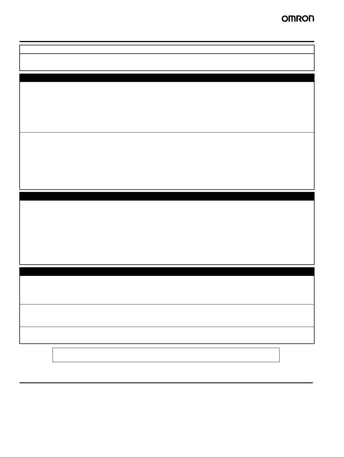
Warranty and Application Considerations
Read and Understand This Catalog
Please read and understand this catalog before purchasing the products. Please consult your OMRON representative if you
have any questions or comments.
Warranty and Limitations of Liability
WARRANTY
OMRON's exclusive warranty is that the products are free from defects in materials and workmanship for a period of one year (or
other period if specified) from date of sale by OMRON.
OMRON MAKES NO WARRANTY OR REPRESENTATION, EXPRESS OR IMPLIED, REGARDING NON-INFRINGEMENT,
MERCHANTABILITY, OR FITNESS FOR PARTICULAR PURPOSE OF THE PRODUCTS. ANY BUYER OR USER
ACKNOWLEDGES THAT THE BUYER OR USER ALONE HAS DETERMINED THAT THE PRODUCTS WILL SUITABLY MEET
THE REQUIREMENTS OF THEIR INTENDED USE. OMRON DISCLAIMS ALL OTHER WARRANTIES, EXPRESS OR
IMPLIED.
LIMITATIONS OF LIABILITY
OMRON SHALL NOT BE RESPONSIBLE FOR SPECIAL, INDIRECT, OR CONSEQUENTIAL DAMAGES, LOSS OF PROFITS,
OR COMMERCIAL LOSS IN ANY WAY CONNECTED WITH THE PRODUCTS, WHETHER SUCH CLAIM IS BASED ON
CONTRACT, WARRANTY, NEGLIGENCE, OR STRICT LIABILITY.
In no event shall the responsibility of OMRON for any act exceed the individual price of the product on which liability is asserted.
IN NO EVENT SHALL OMRON BE RESPONSIBLE FOR WARRANTY, REPAIR, OR OTHER CLAIMS REGARDING THE
PRODUCTS UNLESS OMRON'S ANALYSIS CONFIRMS THAT THE PRODUCTS WERE PROPERLY HANDLED, STORED,
INSTALLED, AND MAINTAINED AND NOT SUBJECT TO CONTAMINATION, ABUSE, MISUSE, OR INAPPROPRIATE
MODIFICATION OR REPAIR.
Application Considerations
SUITABILITY FOR USE
OMRON shall not be responsible for conformity with any standards, codes, or regulations that apply to the combination of
products in the customer's application or use of the products.
Take all necessary steps to determine the suitability of the product for the systems, machines, and equipment with which it will
be used.
Know and observe all prohibitions of use applicable to this product.
NEVER USE THE PRODUCTS FOR AN APPLICATION INVOLVING SERIOUS RISK TO LIFE OR PROPERTY WITHOUT
ENSURING THAT THE SYSTEM AS A WHOLE HAS BEEN DESIGNED TO ADDRESS THE RISKS, AND THAT THE OMRON
PRODUCTS ARE PROPERLY RATED AND INSTALLED FOR THE INTENDED USE WITHIN THE OVERALL EQUIPMENT OR
SYSTEM.
Disclaimers
PERFORMANCE DATA
Performance data given in this catalog is provided as a guide for the user in determining suitability and does not constitute a
warranty. It may represent the result of OMRON's test conditions, and the users must correlate it to actual application
requirements. Actual performance is subject to the OMRON Warranty and Limitations of Liability.
CHANGE IN SPECIFICATIONS
Product specifications and accessories may be changed at any time based on improvements and other reasons. Consult with
your OMRON representative at any time to confirm actual specifications of purchased product.
DIMENSIONS AND WEIGHTS
Dimensions and weights are nominal and are not to be used for manufacturing purposes, even when tolerances are shown.
ALL DIMENSIONS SHOWN ARE IN MILLIMETERS.
To convert millimeters into inches, multiply by 0.03937. To convert grams into ounces, multiply by 0.03527.
Cat. No. H150-E1-01
In the interest of product improvement, specifications are subject to change without notice.
OMRON Corporation
Industrial Automation Company
Control Devices Division H.Q.
Analog Controller Division
Shiokoji Horikawa, Shimogyo-ku,
Kyoto, 600-8530 Japan
Tel: (81)75-344-7080/Fax: (81)75-344-7189
Printed in Japan
0606-1M (0606) (C)
 Loading...