

Page 1

Cat. No. H099-E1-1
Digital Controller CompoBus/D
(DeviceNet) Type
E5EK
USER’S MANUAL
Page 2

I
This highfunction digital controller uses CompoBus/D (DeviceNet) as the commu
nications function on a regular E5EK controller. From here on, the E5EKjjjDRT
controller that supports the CompoBus/D (DeviceNet) communications function is
abbreviated to E5EKDRT.
• Use the CompoBus/D (DeviceNet) for communications.
• Select from many types of temperature and analog input (multiple input)
• Select output functions such as control output or alarm (output assignment)
• Use the HBA (heater burnout alarm) function.
• Use remote SP input.
• Monitor the control loop by LBA (Loop Break Alarm)
• Calibrate input
• It also features a watertight construction (NEMA4: equivalent to IP66)
This User’s Manual describes how to use the E5EKDRT digital controller.
Before using your E5EKDRT, thoroughly read and understand this manual in order
to ensure correct use.
PRECAUTIONS IN USING THE PRODUCT
When the product is used under the circumstances or environment below, ensure ad
herence to limitations of the ratings and functions. Also, take countermeasures for
safety precautions such as failsafe installations.
(1) Use under circumstances or environments which are not described in this user’s manual.
(2) Use for nuclear power control, railway, air craft, vehicle, incinerator, medical equipment, enter
tainment equipment, safety device, etc.
(3) Use for applications where death or serious property damage is possible and extensive safety pre
cautions are required.
This product has been tested by ODV A’s authorized Independent Test Lab and found to comply with ODVA
Conformance Test Software Version 2.0-1.00.
About this manial
E OMRON, 1997
(1) All rights reserved. No part of this publication may be reproduced, stored in a retrieval system, or transmitted,
in any form, or by any means, mechanical, electronic, photocopying, recording, recording, or otherwise, without
the prior written permission of OMRON.
(2) No patent liability is assumed with respect to the use of the information contained herein.
(3) Moreover, because OMRON is constantly striving to improve its high-quality products, the information in this
manual is subject to change without notice. Every precaution has been taken in the preparation of this manual.
Nevertheless, OMRON assumes no responsibility for errors or omissions. Neither is any liability assumed for
damages resulting from the use of the information contained in this publication.
Preface
Page 3
II
+ Meanings of Abbreviations
Sometimes the following abbreviations are used in parameter names, figures and in text
explanations. These abbreviations mean the following.
Abbreviation Term
PV Process value
SP Set point
RSP Remote set point
LSP Local set point
LBA Loop break alarm
HB Heater burnout
AT Autotuning
EU Engineering unit *1
*1 _C, m, g and other units are indicated for scaled data. However, EU" is used as the minimum
unit for the data. For example, for 50.02 (m)", 1EU is taken as the minimum unit 0.01 (m).
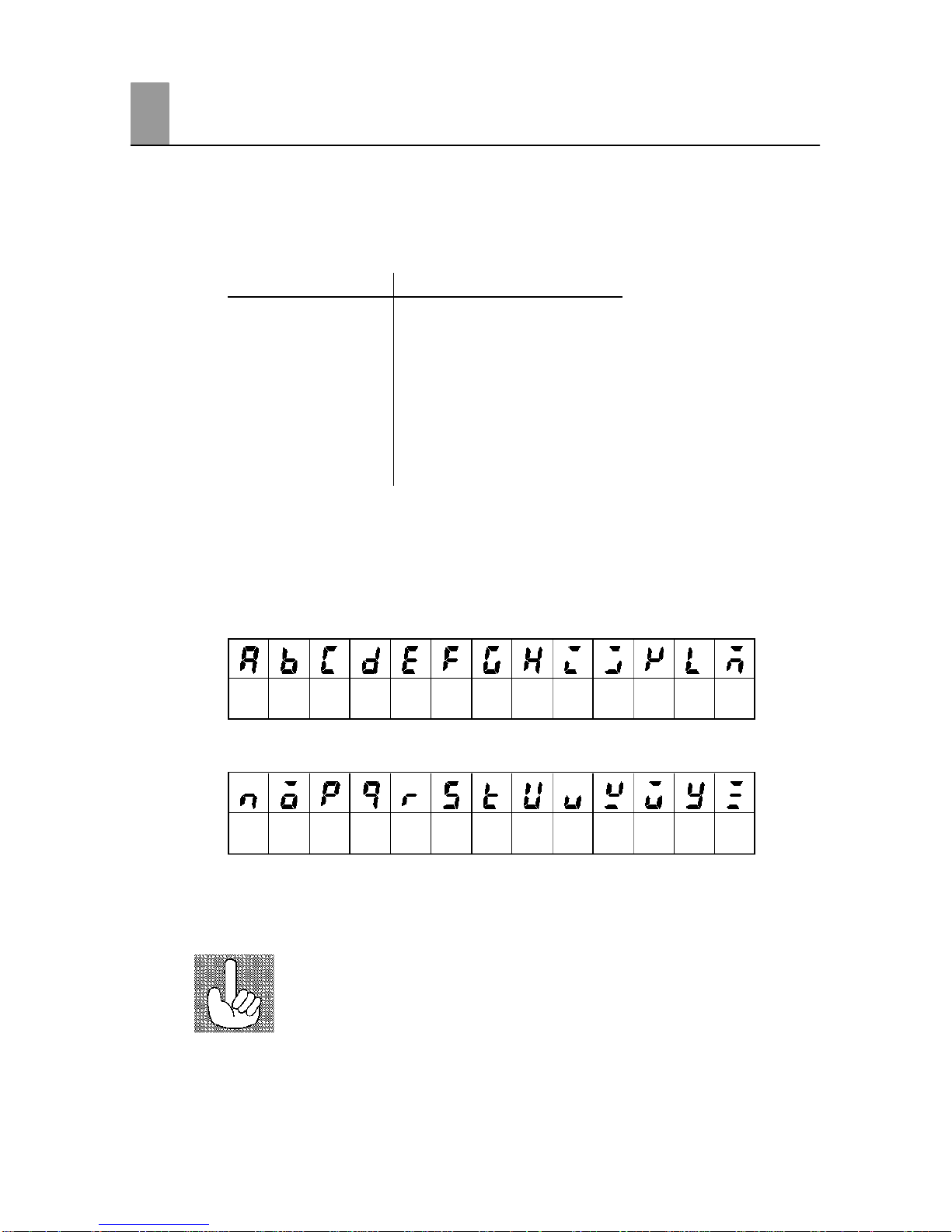
+ How to Read Display Symbols
The following tables show the correspondence between the symbols displayed on the displays
and alphabet characters.
ABCDEFGHI JKLM
NOPQRSTUVWXYZ
+“Reference” mark
This mark indicates that extra, useful information follows, such as supplementary explanations
and how to apply functions.
Conventions Used in This Manual
Page 4

III
+ How this Manual is Organized
Purpose Title Description
D Learning about the
general features of the
E5EK-DRT
Chapter 1 Introduction This chapter describes the fea
tures of the E5EKDRT, names of
parts, and typical functions.
D Setting up
Chapter 2 Preparations This chapter describes the opera
tions that you must carry out
(e.g. installation, wiring and
switch settings) before you can
use the E5EKDRT.
D Basic E5EK-DRT
operations
Chapter 3 Basic Operation
Chapter 5 Parameters
These chapters describe how to
use the front panel keys and how
to view the display when setting
the parameters of the major func
tions for the E5EKDRT.
D Applied E5EK-DRT
operations
Chapter 4 Applied Operation
Chapter 5 Parameters
These chapters describe the
important functions of the
E5EKDRT and how to use the
parameters for making full use of
the E5EKDRT.
D CompoBus/D (DeviceNet)
communication
Chapter 6 Using the Compo
Bus/D (DeviceNet)
This chapter mainly describes
using for the E5EKDRT on the
CompoBus/D (DeviceNet).
D Calibration
Chapter 7 Calibration This chapter describes how the
user should calibrate the E5EK
DRT.
D Troubleshooting
Chapter 8 Troubleshooting This chapter describes what to do
if any problems occur.
Page 5
IV
PRECAUTIONS ON SAFETY
F Marks For Ensuring Safe Use and Their Meanings
This manual uses the following marks to indicate precautions for ensuring that the
E5EKDRT is used safely.
The precautions indicated below describe important information regarding safety. Be
sure to follow the instructions described in these precautions.
WARNING
Indicates information that, if not heeded, could
possibly result in loss of life or serious injury.
CAUTION
Indicates information that, if not heeded, could
result in relatively serious or minor injury, damage to the product, or faulty operation.
F Warning Symbols
WARNING
Do not touch the terminals while the power is ON.
This may cause an electric shock.
CAUTION
D The life expectancy of the output relay varies considerably according to its the output relay within
its rated load and electrical life expectancy, if the output relay is used beyond its life expectancy,
its contacts may become fused or burned.
D Do not allow metal fragments or lead wire scraps to fall inside this product.
This may cause electric shock, fire or malfunction.
D Never disassemble, repaire or modify the product.
This may cause electric shock, fire or malfunction.
D Use the product within the rated load.
This may cause damage or burning.
D Use this product within the rated supply voltage.
This may cause damage or burning.
D Tighten the terminal screws properly. Tightening torque:0.78NSm
Loose screws might cause malfunction.
Correctly set the settings on this product matched to the control target.
If the settings are not compatible with the control target, the product might operate in an unexpected
manner, resulting in damage to the product or an accident.
D To maintain safety in the event of a product malfunction, we recommend taking safety measures,
for example, installing an excessive temperature rise prevention alarm on a separate line.
If malfunction prevents control, this may result in a major accident.
D Use a screwdriver or similar tool to remove the output unit if it is hard to remove.
If you attempt to remove it by applying excessive force, you may be injured by pointed pins.
Page 6

V
NOTICE
Be sure to observe these precautions to ensure safe use.
(1) Do not wire the terminals which are not used.
(2) Be sure to wire properly with correct polarity of terminals.
(3) To reduce induction noise, separate the highvoltage or largecurrent power lines from other lines,
and avoid parallel or common wiring with the power lines when you are wiring to the terminals.
We recommend to use separating pipes, ducts, or shielded lines.
(4) Do not use this product in the following places:
• Places subject to dust or corrosive gases (in particular, sulfide gas and ammonia gas)
• Places subject to high humidity, condensation or freezing.
• Places subject to direct sunlight.
• Places subject vibration and large shocks.
• Places subject to splashing liquid or oil atmosphere.
• Places directly subject to heat radiated from heating equipment.
• Places subject to intense temperature changes.
• Places subject to flammable or explosive gas.
(5) To allow heat to escape, do not block the area around the product. (Ensure enough space for heat
to escape.)
(6) If you remove the controller from its case, never touch nor apply shock to the electronic parts
inside.
(7) Cleaning: Do not use paint thinner or the equivalent. Use standard grade alcohol to clean the product.
(8) Use specified size (M3.5, width 7.2mm or less) crimped terminals for wiring.
(9) Allow as much space as possible between the controller and devices that generate a powerful hig
frequency (e.g. highfrequency welders, highfrequency sewing machines) or surge.
PRECAUTIONS FOR ENSURING CORRECT USE
F Use a 100 to 240 V AC (50/60 Hz), 24 VAC (50/60 Hz) or 24 VDC power supply matched to the power
specifications of the E5EKDRT. Also, make sure that rated voltage is attained within two seconds
of turning the power ON.
F Attach a surge suppressor or noise filter to peripheral devices that generate noise (in particular, motors,
transformers, solenoids, magnetic coils or other equipment that have an inductance component).
F When mounting a noise filter on the power supply, be sure to first check the filter’s voltage and cur
rent capacity, and then mount the filter as close as possible to the controller.
F Insert a noise filter (TDK ZCB220611 or equivalent) on the AC power line to satisfy conducted emis
sion rating (FCC Regulation Class A EN500812compliant).
F Use within the following temperature and humidity ranges:
• Temperature: 10 to 55°C, Humidity: 35 to 85% (with no icing or condensation)
If the E5EKDRT is installed inside a control board, the ambient temperature must be kept to under
55°C, including the temperature around the controller.
If the controller is subjecte d to heat radiation, use a fan to cool the surface of the controller to under 55°C.
F Store within the following temperature and humidity ranges:
• Temperature: 25 to 65°C, Humidity: 35 to 85% (with no icing or condensation)
F Never place heavy objects on, or apply pressure to the controller that may cause it to deform and dete
riorate during use or storage.
F Avoid using the controller in places near a radio, television set, or wireless installation. These devices
can cause radio disturbances which adversely affect the performance of the controller.
Page 7

Preface I . . . . . . . . . . . . . . . . . . . . . . . . . . . . . . . . . . . . . .
Conventions Used in This Manual II . . . . . . . . . . . . . . .
Precautions on Safety IV . . . . . . . . . . . . . . . . . . . . . . . . .
CHAPTER 1 INTRODUCTION 1–1 . . . . . . . . . . . . . . . . . . . . . . . . . . .
This chapter introduces the E5EK-DRT. First-time users should read this chapter without fail.
For details on how to use the controller and parameter settings, see Chapters 2 onwards.
1.1 Names of parts 1–2 . . . . . . . . . . . . . . . . . . . . . . . . . . . . . . . . . . . . . . . . . .
1.2 Input and Output 1–4 . . . . . . . . . . . . . . . . . . . . . . . . . . . . . . . . . . . . . . . . .
1.3 Parameters and Menus 1–6 . . . . . . . . . . . . . . . . . . . . . . . . . . . . . . . . . . .
1.4 About the Communications Function for the
CompoBus/D (DeviceNet) Network 1–9 . . . . . . . . . . . . . . . . . . . . . . . . .
1.5 About Calibration 1–10 . . . . . . . . . . . . . . . . . . . . . . . . . . . . . . . . . . . . . . . .
CHAPTER 2 PREPARATIONS 2–1 . . . . . . . . . . . . . . . . . . . . . . . . . .
This chapter describes the operations you should carry out before turning the E5EK-DRT ON.
2.1 Setting up 2–2 . . . . . . . . . . . . . . . . . . . . . . . . . . . . . . . . . . . . . . . . . . . . . . .
2.2 Installation 2–4 . . . . . . . . . . . . . . . . . . . . . . . . . . . . . . . . . . . . . . . . . . . . . .
2.3 Wiring Terminals 2–7 . . . . . . . . . . . . . . . . . . . . . . . . . . . . . . . . . . . . . . . . .
CHAPTER 3 BASIC OPERATION 3–1 . . . . . . . . . . . . . . . . . . . . . . . .
This chapter describes an actual example for understanding the basic operation of the E5EK-DRT.
3.1 Convention Used in this Chapter 3–2 . . . . . . . . . . . . . . . . . . . . . . . . . . .
3.2 Setting Input Specifications 3–4 . . . . . . . . . . . . . . . . . . . . . . . . . . . . . . .
3.3 Setting Output Specifications 3–7 . . . . . . . . . . . . . . . . . . . . . . . . . . . . . .
3.4 Setting Alarm Type 3–10 . . . . . . . . . . . . . . . . . . . . . . . . . . . . . . . . . . . . . . .
3.5 Protect Mode 3–13 . . . . . . . . . . . . . . . . . . . . . . . . . . . . . . . . . . . . . . . . . . . .
3.6 Starting and Stopping Operation 3–14 . . . . . . . . . . . . . . . . . . . . . . . . . . .
3.7 Adjusting Control Operation 3–15 . . . . . . . . . . . . . . . . . . . . . . . . . . . . . . .
CHAPTER 4 APPLIED OPERATION 4–1 . . . . . . . . . . . . . . . . . . . . .
This chapter describes each of the parameters required for making full use of the features of the
E5EK-DRT. Read this chapter while referring to the parameter descriptions in chapter 5.
4.1 Selecting the Control Method 4–2 . . . . . . . . . . . . . . . . . . . . . . . . . . . . . .
4.2 Operating Condition Restrictions 4–4 . . . . . . . . . . . . . . . . . . . . . . . . . . .
4.3How to Use the Remote SP 4–7 . . . . . . . . . . . . . . . . . . . . . . . . . . . . . . . . .
4.4 How to Use the Heater Burnout Alarm 4–9 . . . . . . . . . . . . . . . . . . . . . .
4.5 LBA 4–11 . . . . . . . . . . . . . . . . . . . . . . . . . . . . . . . . . . . . . . . . . . . . . . . . . . . .
CHAPTER 5 PARAMETERS 5–1 . . . . . . . . . . . . . . . . . . . . . . . . . . . .
This chapter describes the parameters of the E5EK-DRT. Use this chapter as a reference guide.
Conventions Used in this Chapter 5–2 . . . . . . . . . . . . . . . . . . . . . . . . . . . . . .
Protect Mode 5–3 . . . . . . . . . . . . . . . . . . . . . . . . . . . . . . . . . . . . . . . . . . . . . . . .
Manual Mode 5–5 . . . . . . . . . . . . . . . . . . . . . . . . . . . . . . . . . . . . . . . . . . . . . . . .
Level 0 Mode 5–6 . . . . . . . . . . . . . . . . . . . . . . . . . . . . . . . . . . . . . . . . . . . . . . . .
Table of Contents
Page 8

Level 1 Mode 5–10 . . . . . . . . . . . . . . . . . . . . . . . . . . . . . . . . . . . . . . . . . . . . . . . .
Level 2 Mode 5–17 . . . . . . . . . . . . . . . . . . . . . . . . . . . . . . . . . . . . . . . . . . . . . . . .
Setup Mode 5–24 . . . . . . . . . . . . . . . . . . . . . . . . . . . . . . . . . . . . . . . . . . . . . . . . .
Expansion Mode 5–31 . . . . . . . . . . . . . . . . . . . . . . . . . . . . . . . . . . . . . . . . . . . . .
Option Mode 5–36 . . . . . . . . . . . . . . . . . . . . . . . . . . . . . . . . . . . . . . . . . . . . . . . . .
Calibration Mode 5–42 . . . . . . . . . . . . . . . . . . . . . . . . . . . . . . . . . . . . . . . . . . . . .
CHAPTER 6 USING COMPOBUS/D (DEVICENET) 6–1 . . . . . . . .
This chapter describes use of the E5EK-DRT as a slave on the CompoBus/D (DeviceNet) network.
6.1 Outline of CompoBus/D (DeviceNet) 6–2 . . . . . . . . . . . . . . . . . . . . . . . .
6.2 Data Refreshing by Communications 6–4 . . . . . . . . . . . . . . . . . . . . . . .
6.3 Setting the Communications Conditions 6–6 . . . . . . . . . . . . . . . . . . . . .
6.4 Data Assignments 6–8 . . . . . . . . . . . . . . . . . . . . . . . . . . . . . . . . . . . . . . . .
6.5 Data Structure 6–10 . . . . . . . . . . . . . . . . . . . . . . . . . . . . . . . . . . . . . . . . . . .
6.6 Data Timing 6–13 . . . . . . . . . . . . . . . . . . . . . . . . . . . . . . . . . . . . . . . . . . . . .
6.7 Sample Ladder 6–14 . . . . . . . . . . . . . . . . . . . . . . . . . . . . . . . . . . . . . . . . . .
CHAPTER 7 CALIBRATION 7–1 . . . . . . . . . . . . . . . . . . . . . . . . . . . . .
This chapter describes procedures for each calibration operation. Read this chapter only when the
controller must be calibrated.
7.1 Structure of Parameters 7–2 . . . . . . . . . . . . . . . . . . . . . . . . . . . . . . . . . .
7.2 Calibrating Thermocouple 7–4 . . . . . . . . . . . . . . . . . . . . . . . . . . . . . . . . .
7.3 Calibrating Platinum Resistance Thermometers 7–7 . . . . . . . . . . . . . .
7.4 Calibrating Current Input 7–9 . . . . . . . . . . . . . . . . . . . . . . . . . . . . . . . . . .
7.5 Calibrating Voltage Input 7–10 . . . . . . . . . . . . . . . . . . . . . . . . . . . . . . . . . .
7.6 Checking Indication Accuracy 7–12 . . . . . . . . . . . . . . . . . . . . . . . . . . . . .
CHAPTER 8 TROUBLESHOOTING 8–1 . . . . . . . . . . . . . . . . . . . . . .
This chapter describes how to find out and remedy the cause if the E5EK-DRT does not function properly.
8.1 Initial Checks 8–2 . . . . . . . . . . . . . . . . . . . . . . . . . . . . . . . . . . . . . . . . . . . .
8.2 How to Use the Error Display 8–3 . . . . . . . . . . . . . . . . . . . . . . . . . . . . . .
8.3 How to Use Error Output 8–5 . . . . . . . . . . . . . . . . . . . . . . . . . . . . . . . . . .
8.4 Checking Operation Restrictions 8–6 . . . . . . . . . . . . . . . . . . . . . . . . . . .
APPENDIX
SPECIFICATIONS A–2 . . . . . . . . . . . . . . . . . . . . . . . . . . . . . . . . . . . . . . . . . . . .
ABOUT CURRENT TRANSFORMER (CT) A–5 . . . . . . . . . . . . . . . . . . . . . .
CONTROL BLOCK DIAGRAM A–6 . . . . . . . . . . . . . . . . . . . . . . . . . . . . . . . . .
Setting and Monitoring Parameter List A–7 . . . . . . . . . . . . . . . . . . . . . . . . . . .
PARAMETER OPERATIONS LIST A–11 . . . . . . . . . . . . . . . . . . . . . . . . . . . . . .
Using the E5EK-DRT in Multi-vendor Applications A–13 . . . . . . . . . . . . . . . .
INDEX
Page 9

CHAPTER 1 INTRODUCTION
1–1
CHAPTER 1
INTRODUCTION
This chapter introduces the E5EKDRT. Firsttime users should read
this chapter without fail.
For details on how to use the controller and parameter settings, see
Chapters 2 onwards.
CHAPTER
1
1.1 Names of parts 1−2 . . . . . . . . . . . . . . . . . . . . . . . .
Main parts 1−2 . . . . . . . . . . . . . . . . . . . . . . . . . . . .
Front panel 1−2 . . . . . . . . . . . . . . . . . . . . . . . . . . .
About the displays 1−3 . . . . . . . . . . . . . . . . . . . . .
How to use keys 1−3 . . . . . . . . . . . . . . . . . . . . . . .
1.2 Input and Output 1−4 . . . . . . . . . . . . . . . . . . . . . .
Input 1−4 . . . . . . . . . . . . . . . . . . . . . . . . . . . . . . . . .
Output 1−5 . . . . . . . . . . . . . . . . . . . . . . . . . . . . . . . .
1.3 Parameters and Menus 1−6 . . . . . . . . . . . . . . . . .
Parameter types 1−6 . . . . . . . . . . . . . . . . . . . . . . .
Selecting modes 1−7 . . . . . . . . . . . . . . . . . . . . . . . .
Selecting parameters 1−8 . . . . . . . . . . . . . . . . . . .
Fixing settings 1−8 . . . . . . . . . . . . . . . . . . . . . . . . .
1.4 About the Communications Function
for the CompoBus/D (DeviceNet) Network 1−9
1.5 About Calibration 1−10 . . . . . . . . . . . . . . . . . . . . . .
Page 10
1–2
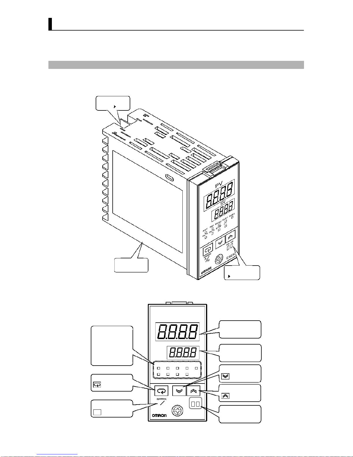
1.1 Names of parts
+ Main parts
P 2-7
Terminals
Rear case
Front panel
This page
+ Front panel
OUT1
SUB1
MANU
STOP
RMT
RST
AT
Operation indicators
A/M key
Mode key
Down key
Up key
No.2 display
No.1 display
E5EK
PV
SV
OUT1 OUT2
MANU
STOP
RMT
AT
SUB2
A/M
OUT2
SUB2
RSP SUB1
M
A
MS NS
MS/NS indicators
Page 11

1–3
+ About the displays
Displays the process value or parameter symbols.
Displays the set point, manipulated variable or parameter settings.
• OUT1 : Lits when the pulse output function assigned to control
output 1" is ON.
• OUT2 : Lits when the pulse output function assigned to control out
put 2" is ON.
• SUB1 : Lits when the output function assigned to auxiliary output
1" is ON.
• SUB2 : Lits when the output function assigned to auxiliary
output 2" is ON.
• MANU : Lits in the manual operation mode.
• STOP : Lits when operation has stopped.
• RMT : Lits during remote operation.
• RSP : Lits during remote SP operation.
• AT : Flashes during autotuning.
Indicates the CompoBus/D (DeviceNet) status.
For details on indicated statuses, see Chapter 8, 8.1 Initial Checks." (page
82).
The following describes basic key operations.
Each press of this key switches between the auto and manual operations.
The functions of this key change according to how long it is pressed. If the
key is pressed for less than one second, the parameters are switched. If the
key is pressed for one second or more, the menu display appears. In key
operations from here on, “press the key" refers to pressing the key for less
than one second.
For details on parameter switching and menu display items, see pages 17
and 18.
Each press of the key increments or advances the values or settings
on the No.2 display, while each press of the key decrements or returns
the values or settings on the No.2 display.
Functions vary, for example, when the
A/M
key is held down simulta
neously with key, or a key is held down continuously. For details, see
page 18. Also, chapters 3 and 4 describe examples using various key com
binations.
’ No.1 disp lay
’ No.2 display
’ Operation
indicators
’ MS/NS indicators
+ How to use keys
’ key
A/M
’ key
’ key
Page 12
CHAPTER 1 INTRODUCTION
1–4
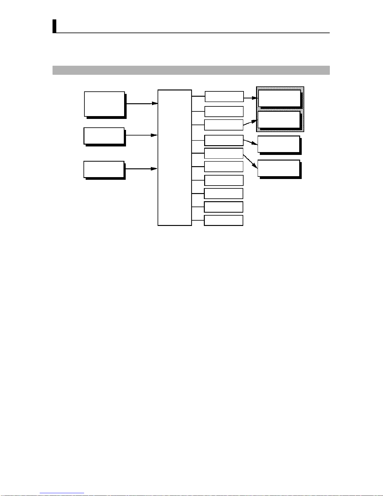
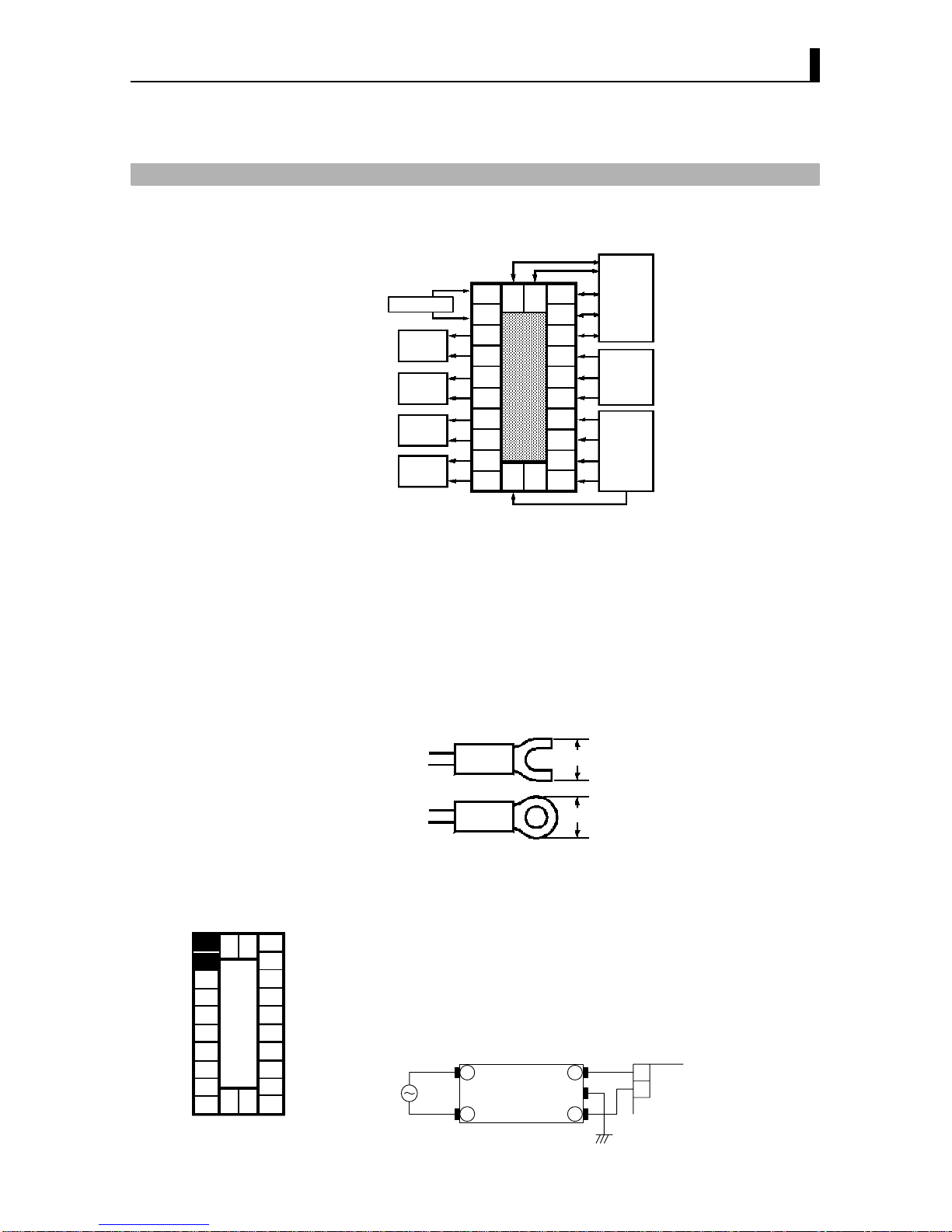
1.2 Input and Output
Temperature input
Voltage input
Current input
CT input
Remote SP input
Controller
Control output
(heat)
Control output
(cool)
Alarm 1
Alarm 2
Alarm 3
HBA
LBA
Error 1
Error 2
Error 3
Control output 1
Control output 2
Auxiliary output 1
Auxiliary output 2
The E5EKDRT supports following inputs: temperature input, current
input, voltage input, CT input and remote SP input.
’ Temperature input/Voltage input/Current input
• Only one of temperature input, voltage input and current input can be
selected and connected to the controller. The above figure shows temper
ature input connected to the controller.
• The following input sensors can be connected for temperature input:
Thermocouple: K, J, T, E, L, U, N, R, S, B, W, PLII
Platinum resistance thermometer: JPt100, Pt100
• The following currents can be connected for current input:
4 to 20 mA, 0 to 20 mA
• The following voltages can be connected for voltage input:
1 to 5 VDC, 0 to 5 VDC, 0 to 10 VDC
• Connect CT input when using the HBA (heater burnout alarm) func
tion. Note that the HBA function cannot be used simultaneously with
the linear output unit.
• When the remote SP function is enabled, inputs within the range 4 to 20
mA are used as the remote SP.
+ Input
’ CT input
’ Remote SP input
Page 13
1.2 Input and Output
1–5
+ Output
The E5EKDRT supports the following four outputs.
Control output 1
Control output 2
Auxiliary output 1
Auxiliary output 2
When using control outputs 1 and 2, set the output unit (sold separately).
Nine output units are available to suit the output circuit configuration.
Note: The output functions of the E5EKDRT do not operate for five se
conds after the E5EKDRT is turned ON.
The E5EKDRT supports the following ten output functions.
Control output (heat)
Control output (cool)
Alarms 1 to 3
HBA
LBA
Error 1 (input error)
Error 2 (A/D converter error)
Error 3 (RSP input error)
Assign these output functions to control output 1, control output 2, auxil
iary ouput 1, and auxiliary output 2.
There are restrictions on how assignment destinations (control output 1,
control output 2, auxiliary output 1, and auxiliary output 2) can be used.
For details, see 3.3 Setting Output Specifications.
In the example on the previous page, control output (heat)" is assigned
to control output 1", alarm 1" is assigned to control output 2", alarm
2" is assigned to auxiliary output 1", and alarm 3" is assigned to auxil
iary output 2". Accordingly, the configuration is such that heating control
output is connected to control output 1, and alarm output is connected to
control output 2 and auxiliary outputs 1 and 2.
Control outputs 1 and 2 are used depending on the differences in control
method as follows.
Control Method
Control Output 1/
Control Output 2
Standard control Control output (heat)/Alarm, etc.,.
Heating and cooling
control
Control output (heat) /
Control output (cool)
’ Output
assignments
Page 14

CHAPTER 1 INTRODUCTION
1–6
1.3 Parameters and Menus
E5EKDRT parameters are distributed between the following nine modes.
Protect mode
Manual mode
Level 0 mode
Level 1 mode
Level 2 mode
Setup mode
Expansion mode
Option mode
Calibration mode
The settings of parameters in each of seven modes (excluding the protect
mode and manual mode) can be checked and modified by selection on the
menu display.
This mode is used to limit use of the keys. The protect function is for pre
venting unwanted modification of parameters and switching between the
auto and manual operation.
In this mode, the controller can be switched manual operation. The
manipulated variable can be manipulated manually only in this mode.
Set the controller to this mode during normal operation. In this mode, you
may change the set point during operation, and stop and start operation.
You can also monitor (not change) the process value, ramp SP and manip
ulated variable.
This is the main mode for adjusting control. In this mode, you can execute
AT (autotuning), and set alarm values, the control period, PID parame
ters and heater burnout alarm (HBA) conditions.
This is the auxiliary mode for adjusting control. In this mode, you can set
the parameters for limiting the manipulated variable, switch between the
remote and local modes, switch between the SP modes, and set the loop
break alarm (LBA), alarm hysteresis and the digital filter value of inputs.
This is the mode for setting the basic specifications. In this mode, you can
set parameters that must be checked or set before operation such as the
input type, scaling, output assignments and direct/reverse operation.
This is the mode for setting expanded functions. In this mode, you can set,
SP setting limiter, selection of 2PID control or ON/OFF control, specifi
cation of the standby sequence resetting method, time for automatic
return to the monitoring display.
Serial communications
Position-proportional control
Event input
Multi-SP
Transfer output
Self-tuning (ST)
Functions not supported
Differences from
General-purpose
Models
CompoBus/D
(DeviceNet)
New function
+ Parameter types
’ Protect mode
’ Manual mode
’ Level 0 mode
’ Level 1 mode
’ Level 2 mode
’ Setup mode
’ Expansion mode
Page 15
1.3 Parameters and Menus
1–7
This is the mode for setting option functions. CompBus/D (DeviceNet)
communications conditions, heater burnout alarm function, and remote
SP scaling parameters are also located in this mode.
This mode is provided so that the user can calibrate inputs.
When calibrating input, the selected input type is calibrated.
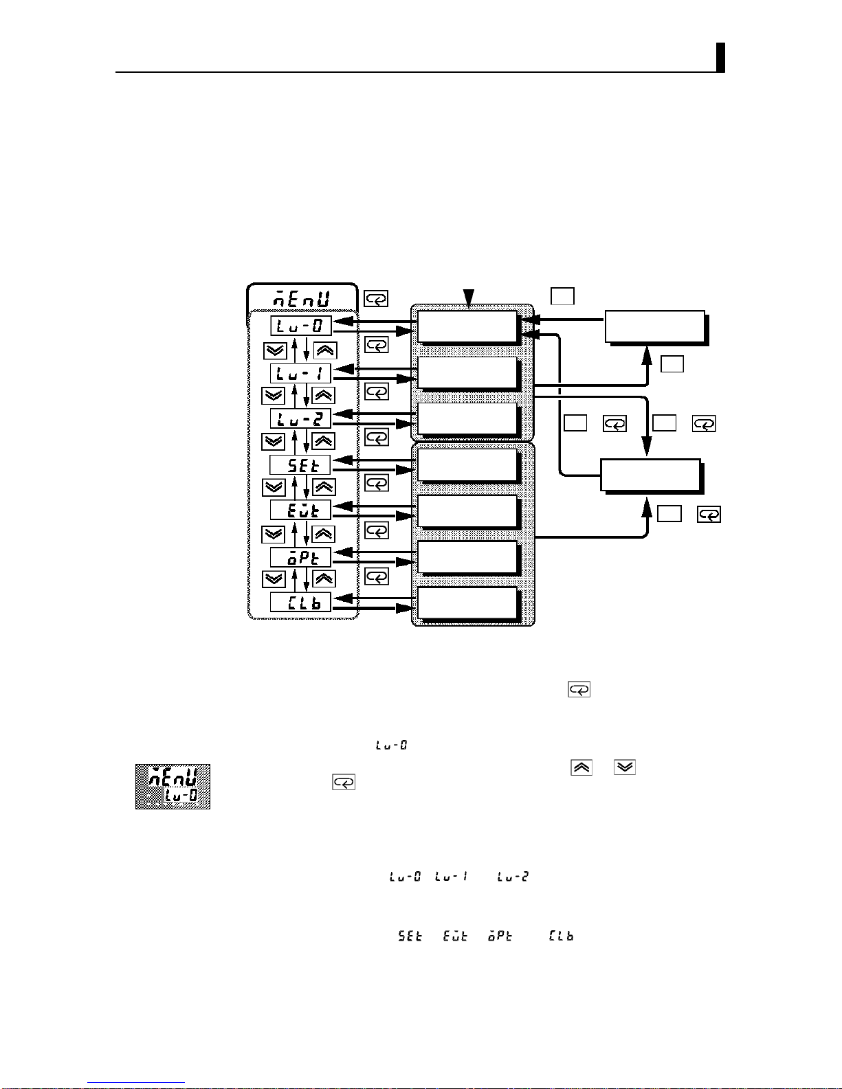
The following diagram shows the order in which modes are selected.
A/M
A/M
A/M
A/M
A/M
++
+
1 second min.
Level 0 mode
Level 1 mode
Level 2 mode
Setup mode
Expansion mode
Option mode
Calibration mode
1 second min.
Manual mode
1 second min.
1 second min. 1 second min.
Protect mode
1 second min.
1 second min.
Power ON
1 second min.
1 second min.
1 second min.
1 second min.
1 second min.
• To select the menu display in any of the above modes (excluding the pro
tect mode and the manual mode), press the key for 1 second mini
mum. The previously specified mode is selected. For example, if you
selected the menu display while in the level 0 mode, the No.2 display
change to [ ] as shown on the left.
• If you select the destination mode using the or keys and press
the key for 1 second minimum when you have selected the menu dis
play, the top parameter in the specified mode is selected.
• Protected modes cannot be selected. Also, the menu display does not
appear when modes are protected up to the level 1 mode.
• If you select [ ] [ ] or [ ] in the menu display, the level 0,
level 1 and level 2 modes, respectively, are selected.
• These modes are selected with control still continuing.
• If you select [ ] [ ] [ ] or [ ] in the menu display, the
setup, expansion, option and calibration modes, respectively, are
selected. When these modes are selected, the control is reset. So, control
outputs and auxiliary output are turned OFF. When another mode is
selected while in these modes, reset is canceled.
’ Option mode
’ Calibration mode
+ Selecting modes
’ Menu display
’ Level 0 to 2
modes
’ Setup mode
’ Expansion mode
’ Option mode
’ Calibration mode
Page 16
CHAPTER 1 INTRODUCTION
1–8
• To set the controller to the protect mode or to return to the level 0 mode
from the protect mode, press the
A/M
key and key for 1 second mini
mun simultaneously.
• To set the controller to the manual mode, press the A/M key for 1 second
minimun in the level 0 to 2 mode. To return to the level 0 mode from the
manual mode, press the A/M key for 1 second minimum.
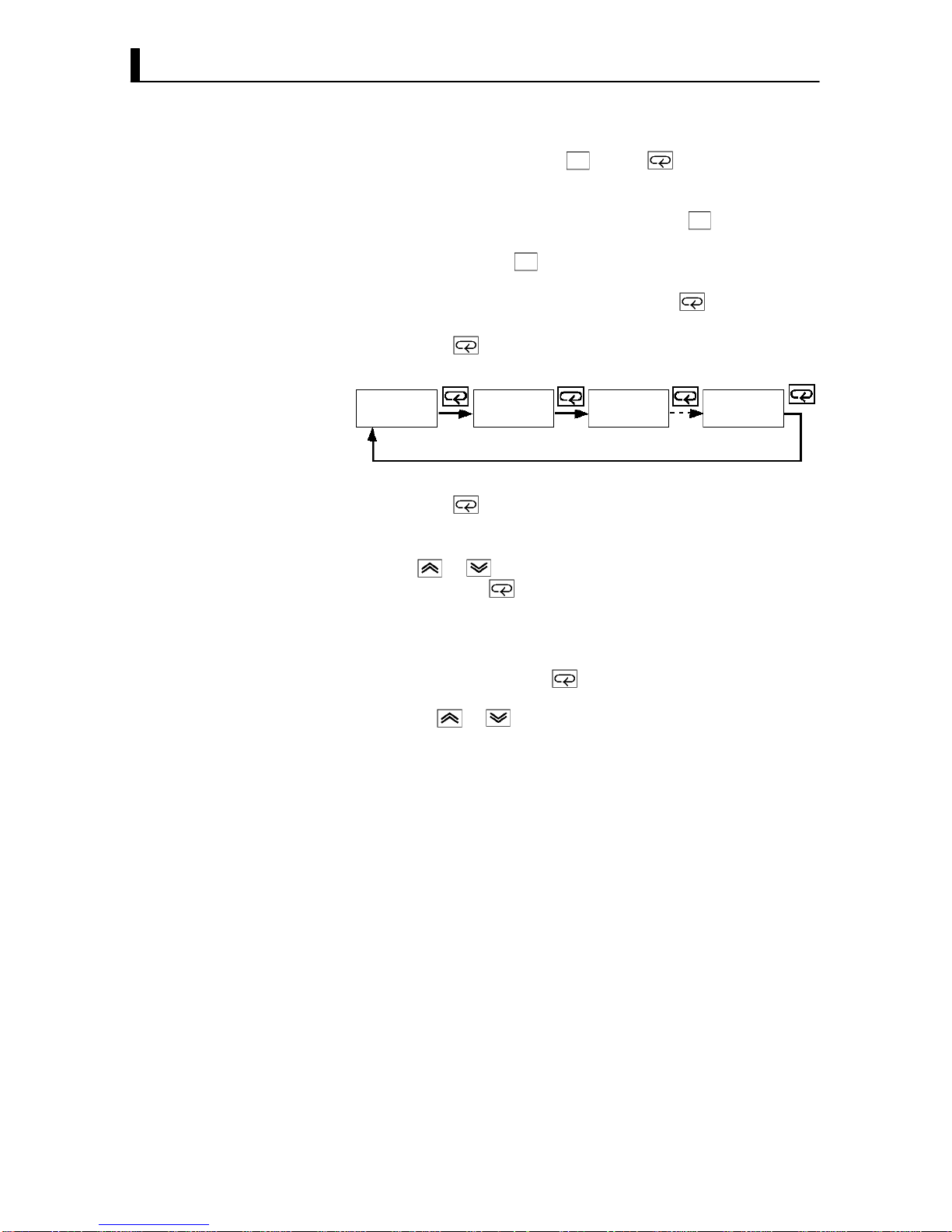
• When not in the manual mode, each press of the key switches the
parameter.
• If you press the key when at the final parameter, the display returns
to the first parameter.
Parameter
1
Parameter
2
Parameter
3
Parameter
n
• If you press the key when at the final parameter, the display returns
to the first parameter.
• When you have changed a parameter setting, specify the parameter
using the or keys, and either leave the setting for at least two
seconds or press the key. This fixes the setting.
• When another mode is selected, the content of the parameters before the
mode was selected is fixed.
• When turning the power OFF, you must first fix the settings and param
eter contents (by pressing the key or selecting another mode). The
settings and parameter contents are sometimes not changed by merely
pressing the or keys.
’ Protect mode
’ Manual mode
+ Selecting
parameters
+ Fixing settings
Page 17
1.4 About the Communications Function for the CompoBus/D (DeviceNet) Network
1–9
1.4 About the Communications Function for
the CompoBus/D (DeviceNet) Network
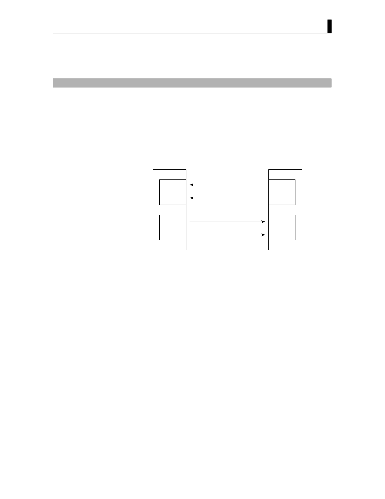
The E5EKDRT operates as a slave on the CompoBus/D (DeviceNet) net
work. Items (parameters, operation instructions and statuses) that have
been assigned as communication data on the E5EKDRT can be uploaded
and downloaded between masters and slaves.
16 read and write operations can be assigned as communication data, and
can be assigned.
Master E5EK-DRT
Parameter (read)
Status
Parameter (write)
Operation instruction
Input area
Output area
Communications read
data assignment
Communications write
data assignment
16
channels
max.
16
channels
max.
As the data structure is flexible like this, communications is possible using
numerous parameter configurations, and the number of parameters can
be limited to increase processing speed.
For details on the type of communication data and how to assign data, see
Chapter 6 Using CompoBus/D (DeviceNet).
For details on cable connections on the CompoBus/D (DeviceNet) net
work, see Chapter 2 Preparations, 2.3 Wiring Terminals (page 27).
For details on CompoBus/D (DeviceNet) such as the network configura
tion and related system devices, see the CompoBus/D (DeviceNet) Opera
tion Manual (catalog No.: W267).
Page 18

CHAPTER 1 INTRODUCTION
1–10
1.5 About Calibration
The E5EKDRT controller is calibrated before shipment from the factory.
So, the user need not calibrate the E5EKDRT controller during regular
use.
However, if the E5EKDRT controller must be calibrated by the user, use
the parameters provided for user to calibrate temperature input, analog
input (voltage, current). In this case, note that the results of calibration
will not be assured.
Also, note that calibration data is updated to the latest value each time the
E5EKDRT controller is calibrated. Calibration data set before shipment
from the factory cannot be returned to after calibration by the user.
The input type selected in the parameter is the item to be calibrated. The
E5EKDRT is provided with the following four calibration parameters.
• Thermocouple
• Platinum resistance thermometer
• Current input
• Voltage input
Two parameters are provided for thermocouple, platinum resistance ther
mometer and voltage input.
When calibrating each item, the calibration data is temporarily regis
tered. This data can be registered as final calibration data only when all
items have been newly calibrated. So, all items must be temporarily regis
tered when calibrating the E5EKDRT controller.
When registering data, information regarding whether or not calibration
has been carried out is also registered.
To calibrate these items, the user must prepare separate measuring
devices and equipment. For details on handling these measuring devices
and equipment, refer to the respective manuals.
For details, see chapter 7 Calibration.
’ Calibrating
inputs
’ Registering
calibration data
Page 19

CHAPTER 2 PREPARATIONS
2–1
CHAPTER 2
PREPARATIONS
This chapter describes the operations you should carry out before turn
ing the E5EKDRT ON.
CHAPTER
2
2.1 Setting up 2−2 . . . . . . . . . . . . . . . . . . . . . . . . . . . . .
Drawout 2−2 . . . . . . . . . . . . . . . . . . . . . . . . . . . . . .
Setting up the output unit 2−3 . . . . . . . . . . . . . .
2.2 Installation 2−4 . . . . . . . . . . . . . . . . . . . . . . . . . . . .
Dimensions 2−4 . . . . . . . . . . . . . . . . . . . . . . . . . . . .
Panel cutout 2−4 . . . . . . . . . . . . . . . . . . . . . . . . . . .
Mounting 2−5 . . . . . . . . . . . . . . . . . . . . . . . . . . . . .
2.3 Wiring Terminals 2−7 . . . . . . . . . . . . . . . . . . . . . .
Terminal arrangement 2−7 . . . . . . . . . . . . . . . . .
Precautions when wiring 2−7 . . . . . . . . . . . . . . .
Wiring 2−7 . . . . . . . . . . . . . . . . . . . . . . . . . . . . . . . .
Page 20
2–2
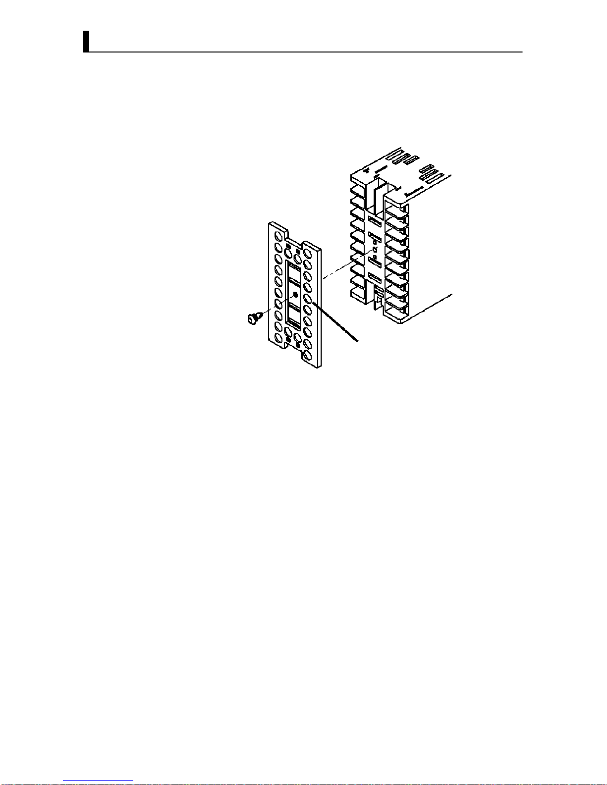
2.1 Setting up
• Set up the output units for control outputs 1 and 2 before mounting the
controller.
• When setting up the output units, draw out the internal mechanism
from the housing and insert the output units into the sockets for control
outputs 1 and 2.
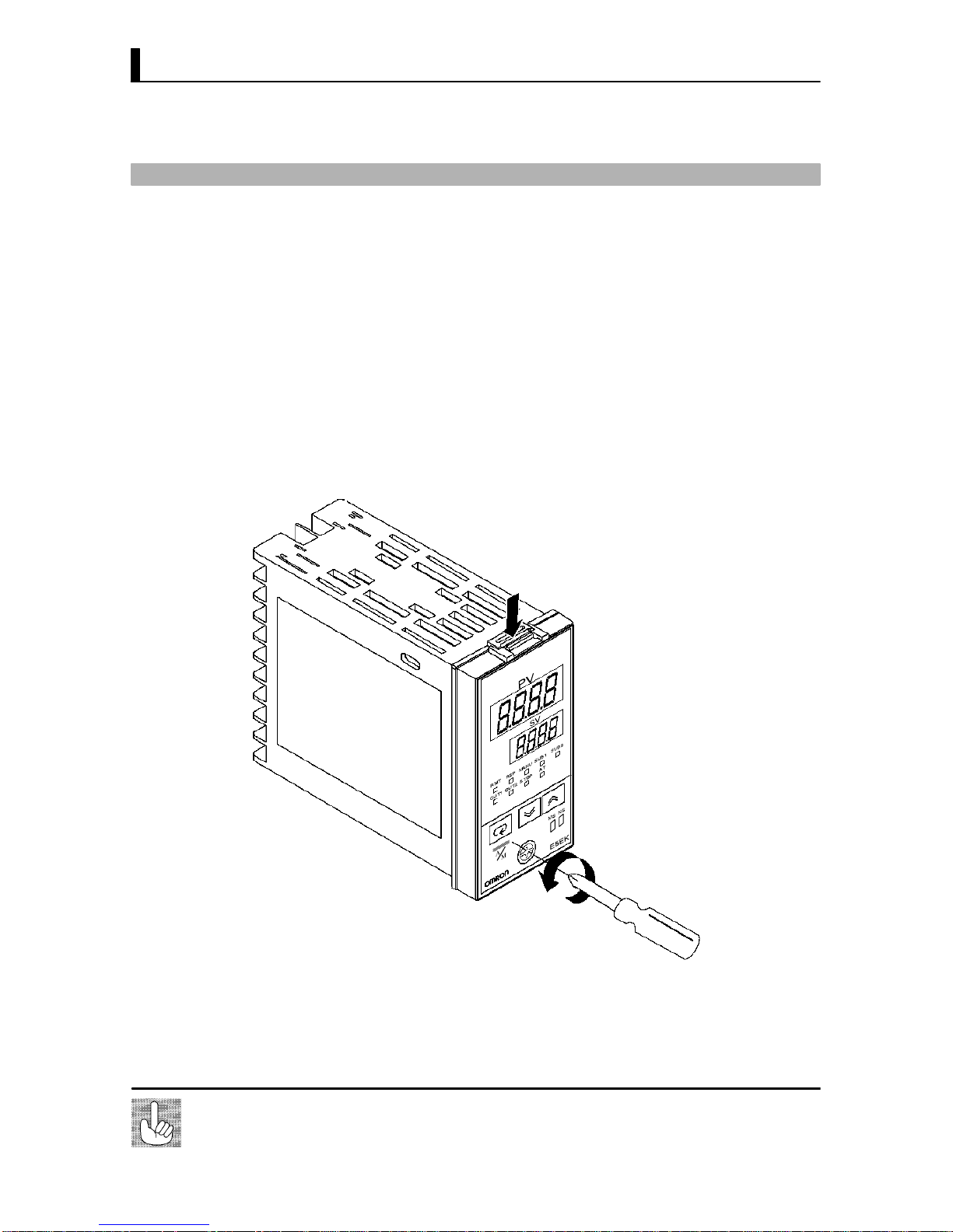
When drawing out the internal mechanism from the housing, prepare a
phillips screwdriver matched to the size of the screw on the lower part of
the front panel.
(1) Press down strongly on the hook on the top of the front panel, and
turn the Phillips screws to the left to loosen the screw on the lower
part of the front panel.
Press down here strongly
(2) Draw out the internal mechanism towards you holding both sides of
the front panel.
Tighten this screw by a torque of 0.3 to 0.5 N⋅m.
Fixing Screw for
Front Panel
+ Draw-out
Page 21
2–3
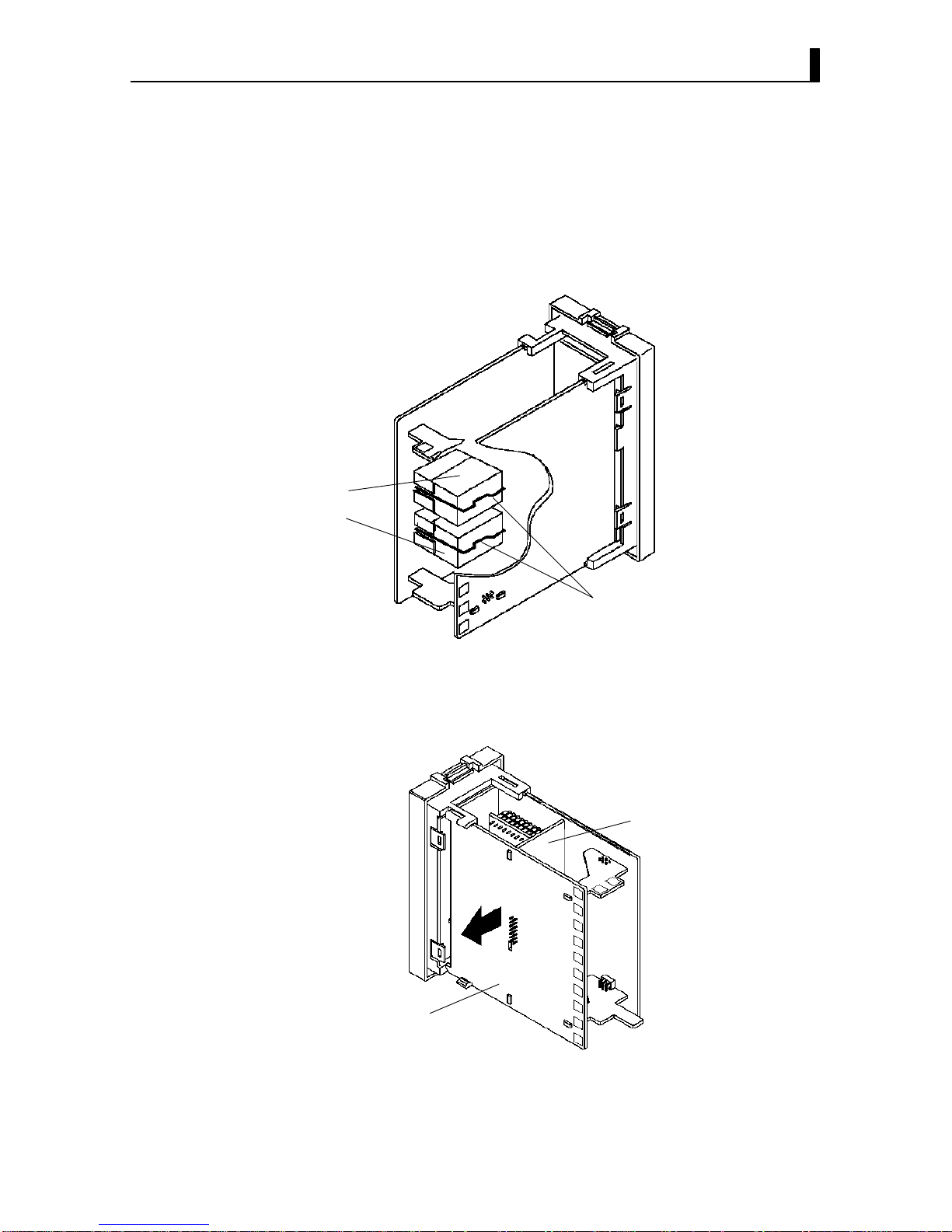
+ Setting up the output unit
• Check the type of the output unit you are about to set up.
• For details on types of output unit and main specifications, see page 28.
(1) Check the positions of the sockets you are about to insert the output
units into as shown in the following diagram.
OUT2
OUT1
Bracket
(2) Remove the power board in the direction of the arrow shown in the
figure. The power board is connected to the control board by a center
connector. Remove this connector taking care not to bend the connec
tor pins.
Power board
Control board
(3) Insert the output unit for control output 1 into the socket OUT1"
and the output unit for control output 2 into the socket OUT2".
(4) Fasten the output units with the bracket (accessory).
(5) Return the power board to its original position.
’ Before setup
’ Procedure
Page 22
CHAPTER 2 PREPARATIONS
2–4
2.2 Installation
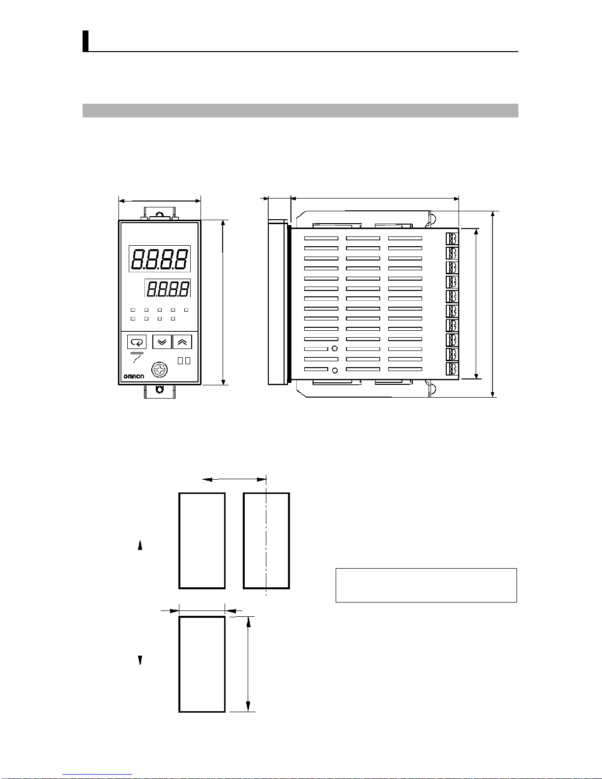
+ Dimensions
E5EK
PV
SV
OUT1 OUT2
MANU
STOP
RMT
AT
SUB2RSP SUB1
48
13.5 100
91
112
A
M
96
• The width of the rear case is 44 mm.
MS NS
Unit (mm)
+ Panel cutout
• Recommended panel thickness is 1 to 8
mm.
• Maintain the specified vertical and hori
zontal mounting space between each con
troller.
Controllers must not be closely mounted
vertically or horizontally.
45
+0.6
0
92
+0.8
0
Unit (mm)
60 min
120 min
Page 23
2.2 Installation
2–5
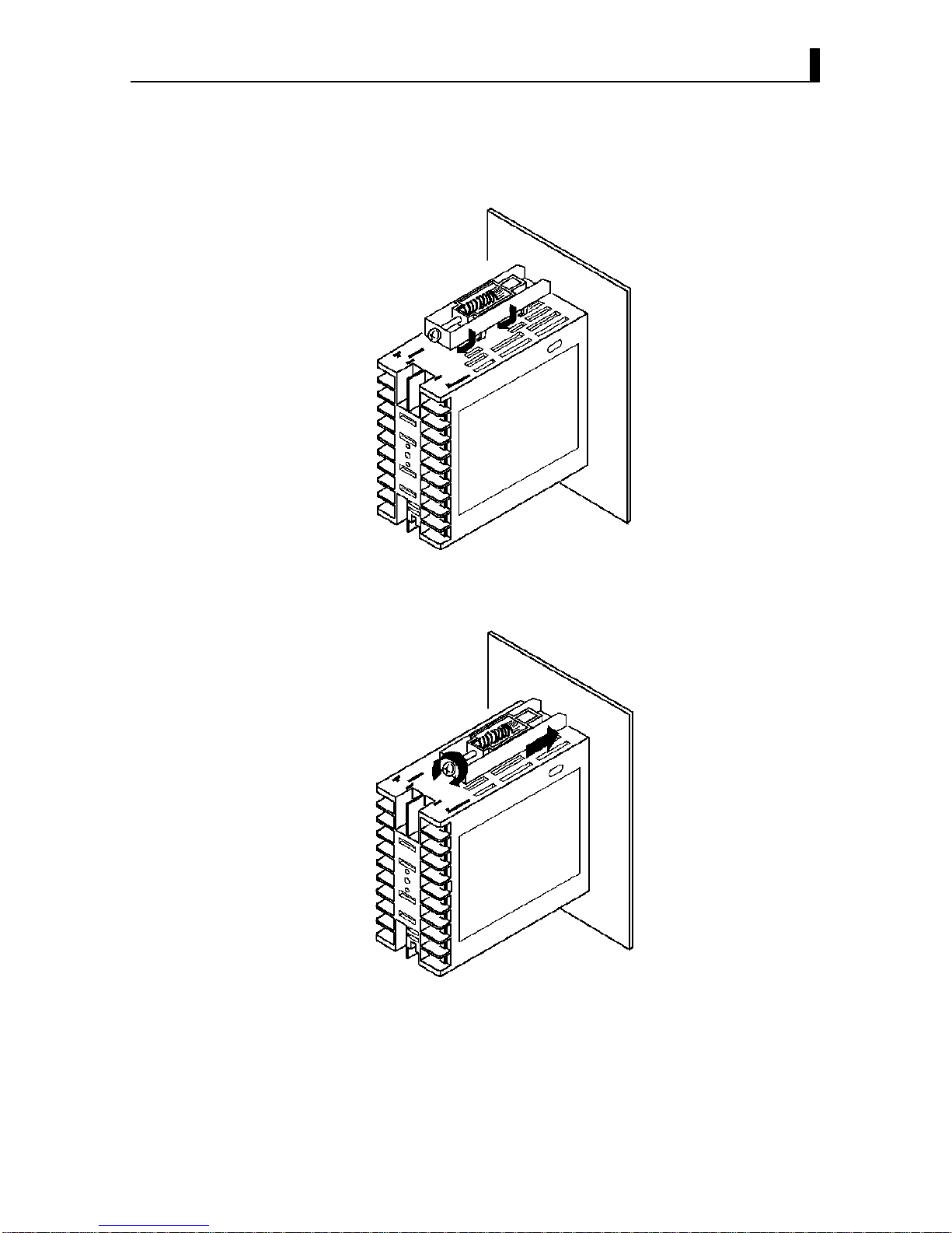
(1) Insert the E5EKDRT controller into the mounting hole in the panel.
(2) Fit the mounting bracket (accessory) into the fixing slots on the top
and bottom of the rear case.
(3) Tighten the mounting bracket screws alternately a little at a time
until the ratchet start to slide.
+ Mounting
Page 24
CHAPTER 2 PREPARATIONS
2–6
’ Setting up the terminal covers
• Fasten the terminal cover (E53COV08) to protect terminals.
• E5EKAA2DRT500 controller is provided with terminal covers.
• Fasten the terminal cover as follows by using the snap pins.
E5EK
-AA2
-DRT
E53-COV08
• To remove the terminal cover, pull the edges of the snap pins.
Page 25
2.3 Wiring Terminals
2–7
2.3 Wiring Terminals
+ Terminal arrangement
10
OUT1
SOURCE
OUT2
SUB1
SUB2
9
8
7
6
5
4
3
2
1
20
19
18
17
16
15
14
13
12
11
21 22
23
RSP
CT
TC
Pt
I
V
SOURCE : 100 to 240VAC, 50/60Hz 15VA
or
24VAC, 50/60Hz 12VA
24VDC, 8W
CompoBus/D
(DeviceNet)
• Use ducts to separate input leads and power lines in order to protect the
controller and its lines from external noise.
• We recommend using solderless terminals when wiring the controller.
• Tighten the terminal screws using a torque no greater than 0.78 N·m.
Take care not to tighten the terminal screws too tightly.
• Do not connect anything to unused terminals.
• Use the following type of solderless terminals for M3.5 screws.
7.2mm max.
7.2mm max.
In the following wiring diagrams, the left side of the terminal Nos. indi
cates the inside of the controller
• Input power to terminal Nos. 9 and 10. Powe r specifications are as follows:
100 to 240VAC, 50/60Hz, 15VA
or
24VAC, 50/60Hz, 12VA
24VDC, 8W (Terminals 9 and 10 have no polarities.)
• When using an AC power supply, connect the noise filter (TDK
ZCB220611 or equivalent) as shown in the figure below.
E5EK-DRT
10
9
1
2
4
3
+ Precautions
when wiring
+ Wiring
’ Power supply
10
9
8
7
6
5
4
3
2
1
20
19
18
17
16
15
14
13
12
11
21 22
23
Page 26
CHAPTER 2 PREPARATIONS
2–8
• Connect the sensor input to terminal Nos. 11 to 14 and 23 as follows ac
cording to the input type.
14
13
12
11
23
14
13
12
11
23
14
13
12
11
23
14
13
12
11
23
–
+
–
+
–
+
mA
Thermocouple Platinum
resistance
thermometer
Voltage input Current input
V
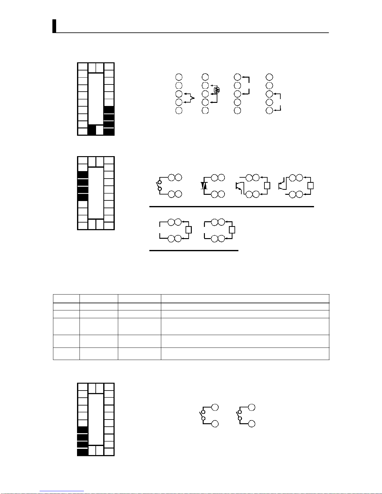
• Terminal Nos. 7 and 8 are for control output 1 (OUT1), and terminal Nos.
5 and 6 are for control output 2 (OUT2). The following diagrams show the
available output units and their internal equalizing circuits.
86
75
86
75
86
75
86
75
86
75
86
75
L
E53-R E53-S E53-Q4
E53-V34
E53-V35
SSR PNP
0 to 10VDC/0 to 5VDC
+
–
GND
Relay
L
+
–
E53-Q
E53-Q3
NPN
E53-C3
E53-C3D
4 to 20mA/0 to 20mA
LL
mA V
+
–
+
–
GND
+v
+v
• With E53VVV output units, about 2VDC is output for one second after
the power is interrupted.
• The following table shows the specifications for each output unit.
Model Output Type Output Method Specifications
E53-R Relay Pulse 250 VAC, 5 A
E53-S SSR Pulse 75 to 250 VAC, 1 A
E53-Q
E53-Q3
E53-Q4
Voltage (NPN)
Voltage (NPN)
Voltage (PNP)
Pulse
Pulse
Pulse
NPN : 12 VDC, 40 mA (with short-circuit protection)
NPN : 24 VDC, 20 mA (with short-circuit protection)
PNP : 24 VDC, 20 mA (with short-circuit protection)
E53-C3
E53-C3D
4 to 20 mA
0 to 20 mA
Linear
Linear
4 to 20 mA, Permissible load impedance: 600 Ω max., Resolution: Approx. 2600
0 to 20 mA, Permissible load impedance: 600 Ω max., Resolution: Approx. 2600
E53-V34
E53-V35
0 to 10 VDC
0 to 5 VDC
Linear
Linear
0 to 10 VDC, Permissible load impedance: 1 kΩ min., Resolution: Approx. 2600
0 to 5 VDC, Permissible load impedance: 1 kΩ min., Resolution: Approx. 2600
• Terminal Nos.3 and 4 are for auxiliary output 1 (SUB1) and terminal
Nos.1 and 2 are for auxiliary output 2 (SUB2).
• The internal equalizing circuits for the auxiliary outputs are as follows:
4
3
2
1
Auxiliary
output 1
Auxiliary
output 2
• Output specifications are as follows:
SPSTNO, 250VAC, 3A
’ Sensor input
10
9
8
7
6
5
4
3
2
1
20
19
18
17
16
15
14
13
12
11
21 22
23
’ Control output
10
9
8
7
6
5
4
3
2
1
20
19
18
17
16
15
14
13
12
11
21 22
23
’ Auxiliary output
10
9
8
7
6
5
4
3
2
1
20
19
18
17
16
15
14
13
12
11
21 22
23
Page 27
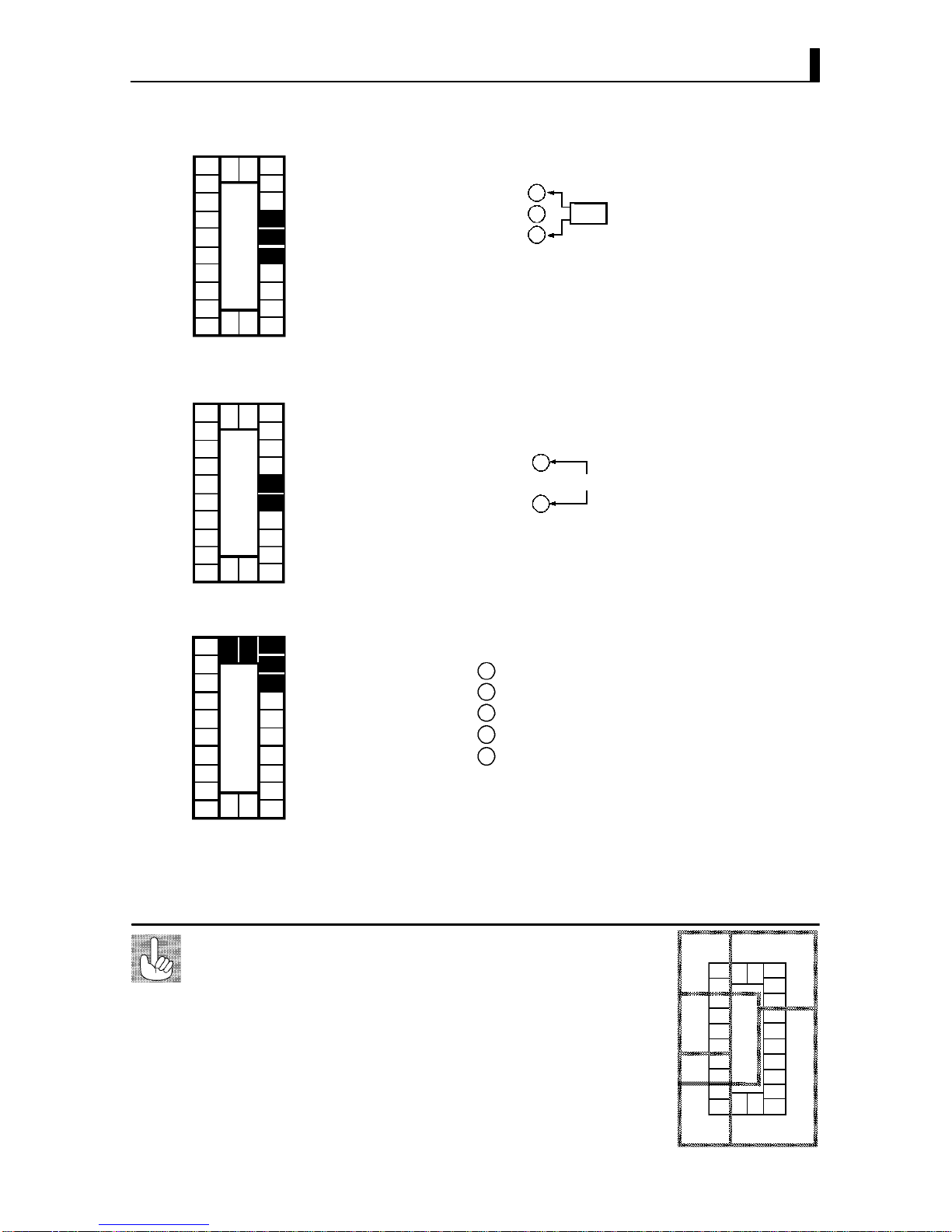
2.3 Wiring Terminals
2–9
• When using the HBA function connect CT input (CT) to terminal Nos.15
to 17.
17
16
15
CT
CT input
• For details on CT inputs, see Appendix, about current transformer.
• Connect an input (RSP) to be used as the remote SP to terminal Nos.15
and 16.
• Only 4 to 20 mA inputs can be connected. Connect the input as follows:
15
+
–
16
4 to 20 mA
• Connect the solderless terminal of the CompoBus/D (DeviceNet) 5core
cable to terminal Nos. 18 to 22. Connect each of the inputs as follows:
18
19
22
21
Red (V+)
White (CAN H)
Blue (CAN L)
Black (V –)
20
(shield)
• For details on the meaning of signals and wiring precautions, see the
CompoBus/D (DeviceNet) Operation Manual (W267)."
The E5EKDRT has independent power supplies for each
of the terminal blocks shown on the right.
About the power
blocks
10
9
8
7
6
5
4
3
2
1
20
19
18
17
16
15
14
13
12
11
2122
23
AC
B
FD
E
’CT input
10
9
8
7
6
5
4
3
2
1
20
19
18
17
16
15
14
13
12
11
21 22
23
’ Remote SP input
10
9
8
7
6
5
4
3
2
1
20
19
18
17
16
15
14
13
12
11
21 22
23
’ Communications
10
9
8
7
6
5
4
3
2
1
20
19
18
17
16
15
14
13
12
11
21 22
23
Page 28

CHAPTER 3 BASIC OPERATION
3–1
CHAPTER 3
BASIC OPERATION
This chapter describes an actual example for understanding the basic
operation of the E5EKDRT.
CHAPTER
3
3.1 Convention Used in this Chapter 3−2 . . . . . . . .
3.2 Setting Input Specifications 3−4 . . . . . . . . . . . . .
Input type 3−4 . . . . . . . . . . . . . . . . . . . . . . . . . . . . .
Temperature input 3−5 . . . . . . . . . . . . . . . . . . . . .
Analog input 3−5 . . . . . . . . . . . . . . . . . . . . . . . . . .
3.3 Setting Output Specifications 3−7 . . . . . . . . . . .
Output assignments 3−7 . . . . . . . . . . . . . . . . . . . .
Direct/reverse operation 3−8 . . . . . . . . . . . . . . . .
Control period 3−8 . . . . . . . . . . . . . . . . . . . . . . . . .
3.4 Setting Alarm Type 3−10 . . . . . . . . . . . . . . . . . . . .
Alarm type 3−10 . . . . . . . . . . . . . . . . . . . . . . . . . . . .
Alarm value 3−10 . . . . . . . . . . . . . . . . . . . . . . . . . . .
Alarm hysteresis 3−11 . . . . . . . . . . . . . . . . . . . . . . .
Close in alarm/open in alarm 3−11 . . . . . . . . . . . .
3.5 Protect Mode 3−13 . . . . . . . . . . . . . . . . . . . . . . . . . .
Security 3−13 . . . . . . . . . . . . . . . . . . . . . . . . . . . . . . .
A/M key protect 3−13 . . . . . . . . . . . . . . . . . . . . . . . .
3.6 Starting and Stopping Operation 3−14 . . . . . . . .
3.7 Adjusting Control Operation 3−15 . . . . . . . . . . . .
Changing the set point 3−15 . . . . . . . . . . . . . . . . .
Manual operation 3−15 . . . . . . . . . . . . . . . . . . . . . .
Autotuning (A.T.) 3−17 . . . . . . . . . . . . . . . . . . . . .
Page 29
3–2
3.1 Convention Used in this Chapter
This chapter describes basic E5EKDRT operations such as how to set up
parameters, start and stop operation, and adjusting control operation.
For more complex control examples, refer to Chapter 4 Applied Operation
and Chapter 5 Parameters.
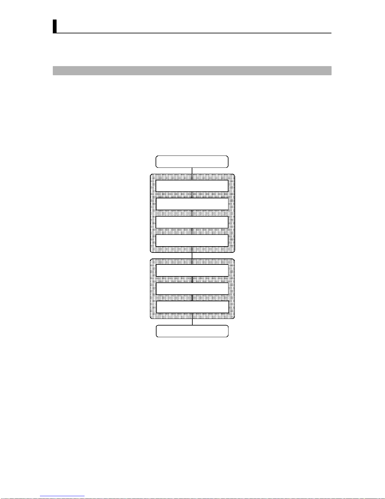
The following diagram shows the basic operation flow.
Power ON
Setup
Setting input specifications
Setting output specifications
Setting alarm output
Protecting parameters
Operation
Start
Adjustment
Stop
Power OFF
This chapter describes basic operation according to this flow. Examples of
operation for each of these items are described at the end of the setting
examples for the parameter in question. However, you must proceed to the
first parameter of the subsequent item.
For example, to perform setting output specifications" after completing
setting input specifications," proceed to the first parameter of setting
output specifications" from the final parameter of setting input specifica
tions." For details on moving parameters between items, follow the proce
dures in Selecting modes" and Selecting parameters" described on
pages 17 and 18.
’ Basic Operation
Flow
Page 30
3–3
The following are examples of how to set up each of the items. These exam
ples assume that the controller is operated at the factory defaults.
The main specifications of the setup examples in this chapter are as fol
lows:
• A K thermocouple is connected to the controller.
• The control output (heat) function is assigned to control output 1, and
the alarm 2 function is assigned to auxiliary output 1. A relay output
unit is also attached to control output 1.
• The upper limit alarm is set. In this example, alarm 2 is set. An alarm
is output when the temperature exceeds 10_C of the set point.
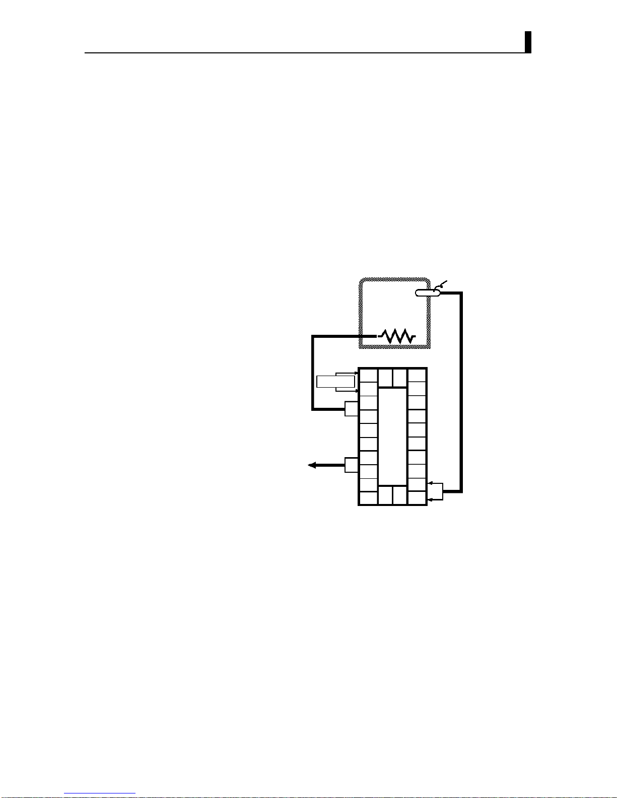
The control example that is configured based upon the setup example is
as follows:
OUT1
Temperature sensor:
K thermocouple
Alarm 2 (upper limit)
(alarm value=10_C)
Control target
SUB1
–
+
E5EK-AA2-DRT
(Control output 1: E53-R)
10
9
8
7
6
5
4
3
2
1
20
19
18
17
16
15
14
13
12
11
21 22
23
SOURCE
’ Setup
Page 31

CHAPTER 3 BASIC OPERATION
3–4
3.2 Setting Input Specifications
Setting input specifications
Input type
Temperature input?
Temperature unit
Temperature input shift
End of setup
Decimal point
Scaling
Setup mode
Level 2 mode
N
Y
• With temperature input, scaling and decimal point parameters need not
be set as this information is determined by the input (sensor) type.
(These parameters are not displayed.) Note that temperature unit and
temperature input shift parameters need to be set.
• With analog input, the scaling upper limit", scaling lower limit" and
decimal point" parameters need to be set.
• Set the type No. (0 to 22) in the input type" parameter (Set up mode).
The factory setting is 2: K (thermocouple)."
• For details on input types and setting ranges, see page 525.
+ Input type
Page 32

3.2 Setting Input Specifications
3–5
+ Temperature input
• To switch the temperature unit from _C" to_F" when input is temper
ature, switch the _C/_F selection" parameter (setup mode) from "
to ".
• When input is temperature input, the upper and lower limit values of the
sensor can be shifted linearly. For example, if both the upper and lower
limit values are shifted by 1.2_C, the process value (before shift) is re
garded as 201.2_C after shift when input is 200_C before shift.
• To set input shift, set shift values in the input shift upper limit" and in
put shift lower limit" parameters (level 2 mode).
0
100
Temperature
Upper limit value
Lower limit value
Input shift upper limit value
After shift
Before shift
Input shift lower
limit value
Input (%FS)
• When the analog input (the voltage input and current input) is selected,
scaling matched to the control is available.
• The scaling upper limit", scaling lower limit" and decimal point" pa
rameters (setup mode) are used for scaling. These parameters cannot be
used when the temperature input type is selected.
• The scaling upper limit" parameter sets the physical quantity to be ex
pressed by the upper limit value of input, and the scaling lower limit"
parameter sets the physical quantity to be expressed by the lower limit
value of input. The decimal point" parameter sets the number of digits
past the decimal point.
• The following figure shows a scaling example of 4 to 20 mA input. After
scaling, the humidity can be directly read. In this case, the decimal
point" parameter is set to 1".
100%FS
0
Readout (humidity)
Scaling upper limit
value (95.0%)
Scaling lower limit
value (10.0%)
Input (4 to 20 mA)
’ Temperature unit
’ Temperature
input shift
+ Analog input
Page 33

CHAPTER 3 BASIC OPERATION
3–6
In this example, let’s check the input type and temperature units, and shift
the lower limit by 1_C and the upper limit by 3_C.
input type" = 2: K"
temperature unit" = _C"
input shift upper limit"= 3.0"
input shift lower limit" = 1.0"
(1) Select the menu display, and select : setup mode" using the
or keys. For details on selecting the menu display, see page 17.
(2) Press the key for one second minimum to enter the setup mode.
The top parameter in the setup mode : input type" is displayed.
This parameter is factoryset to 2: K".
(3) Press the key to fix the set value. The display changes to :
_C/_F selection" parameter. This parameter is factoryset to : _C".
(4) Select the menu display, and select : level 2 mode" using the
or keys.
(5) Press the key for one second minimum to enter the level 2 mode.
The top parameter in the level 2 mode [ ] (local/remote" pa
rameter) is displayed.
(6) Press the key until [ ] (input shift upper limit" parameter)
is selected. This parameter is factoryset to 0.0".
(7) Press the key until 3.0" is displayed.
(8) Press the key until [ ] (input shift lower limit" parameter)
is selected. This parameter is factoryset to 0.0".
(9) Press the key until 1.0" is displayed. This sets the input shift
upper limit" and input shift lower limit" values.
Setting Example
1 second min.
1 second min.
1 second min.
Page 34

3.3 Setting Output Specifications
3–7
3.3 Setting Output Specifications
+ Output assignments
• Ten output are supported.
These functions are assigned to control outputs 1 and 2, and auxiliary
output 1 and 2.
• Restrictions on assignment destination are placed on some of the out
puts. The following table shows where outputs may be assigned to.
Assignment
Control Output Auxiliary Output
Destinati
on
Output Function
1 2 1 2
Control output (heat) F F
Control output (cool) F F
Alarm 1 F F F F
Alarm 2 F F F F
Alarm 3 F F F F
HBA F F F F
LBA F F F F
Error 1; Input error F F
Error 2; A/D converter error F F
Error 3; RSP input error F F
With control output (cool), the conditions for switching from standard control
to heating and cooling control are reached when the output function is assigned
at the cooling side during heating and cooling control.
In other words, heating and cooling control is carried out when control
output (cool) is assigned, and standard control is carried out when out
put is not assigned. For details on heating and cooling control, see 4.1
Selecting the Control Method (page 42).
• Factory settings are as follows:
control output 1 = Control output (heat)
control output 2 = Alarm 1
auxiliary output 1 = Alarm 2
auxiliary output 2 = Alarm 3.
• Output assignments are set in the control output 1 assignment", con
trol output 2 assignment", aux output 1 assignment" and aux output
2 assignment" parameters (setup mode).
Page 35

CHAPTER 3 BASIC OPERATION
3–8
• Direct operation" (or normal operation) refers to control where the
manipulated variable is increased according to the increase in the pro
cess value. Alternatively, reverse operation" refers to control where the
manipulated variable is decreased according to the decrease in the pro
cess value.
For example, when the process value (PV), is lower than the set point
(SP), in a heating control system, the manipulated variable increases by
the difference between the PV and SP values.
Accordingly, this becomes reverse operation" in a heating control system.
Alternatively, this becomes direct operation" in a cooling control system.
• Direct/reverse operation is set in the [ ]direct/reverse operation"
parameter (setup mode).
• When the output unit is pulse output such as relay output, set the pulse
output cycle (control period). Though a shorter pulse period provides
better control performance, the control period should be set taking the
life expectancy of the output unit into consideration when the output
unit is relay. It is recommended that the control period be set to longer
than 20 seconds.
• The control period is set in the control period (heat)" parameter (level
1 mode). Factory setting is 20:20 seconds."
• The control period (cool)" output function is not allocated. So, the
control period (cool)" parameter cannot be set.
+ Direct/reverse
operation
+ Control period
Page 36

3.3 Setting Output Specifications
3–9
In this example, let’s set the parameters as follows:
control output 1 assignment" = control output (heat)"
control output 2 assignment" = alarm output 1"
direct/reverse operation" = reverse operation"
control period" = 20 sec."
All of the above settings in this example are factory settings. So, in this
example, we are only going to check the parameter settings.
(1) Select the menu display, and select [ ] (setup mode) using the
or keys. For details on selecting the menu display, see page
17.
(2) Press the key for one second minimum to enter the setup mode.
The top parameter in the setup mode [ ] input type" is dis
played. In this example, the parameter setting is 17: 4 to 20 mA."
(3) Press the key until [ ] (control output 1 assignment"
parameter) is displayed. The parameter default is [ ].
(4) As the setting in this example is to be left as it is, press the key.
The display changes to [ ] (control output 2 assignment"
parameter). The parameter default is [ ].
(5) As the setting in this example is to be left as it is, press the key
until [ ] (direct/reverse operation" parameter) is displayed.
The parameter default is [ ].
(6) As the setting in this example is to be left as it is, press the or
keys to select [ ] (level 1 mode).
(7) Press the key for one second minimum to enter the level 1 mode.
The top parameter in the level 1 mode [ ] AT execute/cancel" is
displayed.
(8) Press the key until [ ] (control period" parameter) is dis
played. The parameter default is 20". As the setting in this example
is to be left as it is, quit key operation.
Setting Example
1 second min.
1 second min.
1 second min.
Page 37

CHAPTER 3 BASIC OPERATION
3–10
3.4 Setting Alarm Type
• Three alarm outputs are supported: alarms 1 to 3. Of these, only the
alarm assigned as the output can be used.
• Alarm output conditions are determined according to the combination
of the alarm type", alarm value" and alarm hysteresis" parameter
settings.
• The contact conditions when alarm output is ON can be set to open"
or closed" in the close in alarm/open in alarm" parameter.
• The following table shows the alarm types supported by the E5EKDRT
controller and their respective operations.
Alarm Output Operation
Al
arm Type
When X is positive When X is negative
1
Upper-and lower-limit alarm
(deviation)
ON
OFF
XX
SP
Always ON
2
Upper-limit alarm (deviation)
ON
OFF
X
SP
ON
OFF
X
SP
3
Lower-limit alarm (deviation)
ON
OFF
X
SP
X
ON
OFF
SP
4
Upper-and-lower-limit range
alarm (deviation)
ON
OFF
XX
SP
Always OFF
5
Upper-and-lower-limit alarm
with standby sequence
(deviation)
ON
OFF
XX
SP
Always OFF
6
Upper-limit alarm with
standby sequence (deviation)
ON
OFF
X
SP
ON
OFF
X
SP
7
Lower-limit alarm with
standby sequence (deviation)
ON
OFF
X
SP
ON
OFF
X
SP
8
Absolute-value upper-limit
alarm
ON
OFF
X
0
ON
OFF
X
0
9
Absolute-value lower-limit
alarm
ON
OFF
X
0
ON
OFF
X
0
10
Absolute-value upper-limit
alarm with standby sequence
ON
OFF
X
0
ON
OFF
X
0
11
Absolute-value lower-limit
alarm with standby sequence
ON
OFF
X
0
ON
OFF
X
0
• Alarm types are set independently for each alarm in the alarm 1 to 3"
parameters (setup mode). Factory setting is 2: Upperlimit alarm (devi
ation)".
• Alarm values are indicated by X" in the table above. Alarm output
operation differs according to whether the value of the alarm is positive
or negative.
• Alarm values are set independently for each alarm in the alarm value
1 to 3" parameters (level 1 mode). Factory setting is 0".
+ Alarm type
+ Alarm value
Page 38

3.4 Setting Alarm Type
3–11
• The hysteresis of alarm outputs when alarms are switched ON/OFF can
be set as follows.
ON
OFF
Alarm hysteresis
Alarm value
Alarm value
ON
OFF
Upper limit alarm Lower limit alarm
Alarm hysteresis
• Alarm hysteresis is set independently for each alarm in the alarm 1 to
3 hysteresis" parameters (level 2 mode). Factory setting is 0.02:
0.02%FS".
• “Standby sequence" is a function for unconditionally turning alarm out
put OFF when the process value has left the alarm range once and it next
enters the alarm range.
• For example, when the alarm type is set to “deviation lower limit," gener
ally the process value is within the alarm range, and alarm output
become ON as it is as the process value when the power is turned ON is
smaller than the set point. However, if the alarm type is set to deviation
lower limit with standby sequence", alarm output first becomes ON
when the process value exceeds the alarm setting value to leave the
alarm range and once again falls below the alarm value.
• When an alarm is output, the standby sequence is canceled. For details
on the standby sequence reset conditions, see Chapter 5, Expansion
Mode, Standby sequence reset method" on page 534.
+ Close in alarm/open in alarm
• When the controller is set to “close in alarm," the status of the alarm out
put function is output as it is. When set to “open in alarm," the status of
the alarm output function is output inverted.
Alarm
Output Output LED
ON ON Lit
Cl
ose in alarm
OFF OFF Not lit
p
ON OFF Lit
O
pen in alarm
OFF ON Not lit
• Alarm type and close in alarm (normally open)/open in alarm (normally
close) can be set independently for each alarm.
• Close in alarm/open in alarm is set in the alarm 1 to 3 open in alarm"
parameters (setup mode). Factory setting is [ ] close in alarm".
The figure below visually summarizes the above description of alarm
operations (when alarm type is set to lower limit alarm (deviation) with
standby sequence"):
Alarm type: lower limit alarm (deviation)
with standby sequence
Alarm value
Alarm output
(close in alarm)
Standby sequence
canceled
PV
Alarm hysteresis
Time
Close (ON)
Open (OFF)
+ Alarm hysteresis
’ Standby
sequence
’ Summary of
alarm operations
Page 39

The decimal point of the alarm value conforms to the setting of the decimal point"
parameter (setup mode). (During temperature input, the decimal point of the alarm
value conforms to the set sensor.)
About the Decimal
Point of the Alarm
Value
CHAPTER 3 BASIC OPERATION
3–12
When a set point for a temperature exceeds "10%, alarm1 will be output.
In this example, let’s set the parameters as follows:
alarm type 1" = 1: (deviation upperand lowerlimit)"
alarm value 1" = 10"
alarm hysteresis" = 0.20"
close in alarm/open in alarm"= : close in alarm"
Meanings of parameters, alarm histeresis" and open in alarm/close in
alarm" are the same settings at the shipment, so settings for operations
are omitted.
(1) Select the menu display, and select [ ] (setup mode) using the
or keys. For details on selecting the menu display, see page 17.
(2) Press the key for one second minimum to enter the setup mode.
The top parameter in the setup mode [ ] input type" is dis
played. In this example, the parameter setting is 17: 4 to 20 mA".
(3) Press the key until [ ] (alarm type 1" parameter) is dis
played. The parameter default is 2: deviation upper limit".
(4) Press the key to return to 1: deviation upperandlower limit".
(5) Select the menu key, and select [ ] (level 1 mode) using the
or keys.
(6) Press the key for one second minimum to enter the level 1 mode.
The top parameter in the level 1 mode [ ] AT execute/cancel" is
displayed.
(7) Press the key until [ ] (alarm value 1" parameter) is dis
played.
(8) In this example, the parameter setting is 0.0" so press the key
until 10.0" is displayed.
Setting Example
1 second min.
1 second min.
1 second min.
Page 40

3.5 Protect Mode
3–13
3.5 Protect Mode
• This parameter allows you to protect until start of operation parameters
that do not change during operation to prevent unwanted modification.
• The range of usable parameters is specified by the set value of the secu
rity" (protect) parameter.
• The following table shows which modes are protected by this set value:
Set Value
Mode
0 1 2 3 4 5 6
Calibration F
Option F F
Expansion F F
Setup F F
Level 2 F F F
Level 1 F F F F
Level 0 F F F F F *2 *1
*1 The PV/SP" parameter can only the displayed.
*2 Only the PV/SP" parameter can be used.
• When 0" is set, parameters are not protected.
• When 5" is set, only the PV/SP" parameter can be used.
• When 6" is set, the PV/SP" parameter can only be monitored.
• Default is 1".
• This parameter disables use of the A/M key during operation. For exam
ple, if you protect use of the A/M key by the A/M key protect" parameter
(protect mode) during auto operation, the controller cannot be set to the
manual mode, preventing manual operation of the controller during
operation.
• Let’s protect the setup, expansion, option and calibration modes. Set the
parameters as follows:
security" = 2: Usable only in level 0 to 2 modes"
(1) Press for 1 second minium the A/M and keys simultaneously, the
controller enters the protect mode.
(2) In the protect mode, the top parameter in the protect mode security"
is displayed. The parameter default is 1". Press the key to change
the parameter setting to 2".
(3) Press for 1 second minium the A/M and keys simultaneously, the
display changes to the PV/SP monitor" parameter (level 0 mode).
+ Security
•Indicates operable
(unprotected) modes.
+ A/M key protect
Setting Example
A/M
A/M
Page 41

CHAPTER 3 BASIC OPERATION
3–14
3.6 Starting and Stopping Operation
• You can start and stop operation by changing the setting of the run/
stop" parameter (level 0 mode).
• You can switch the RUN/STOP function up to 100,000 times.
• To stop operation, set the run/stop" parameter to [ ] (stop). In a
stop state, the STOP" LED lights.
• Operation cannot be stopped during autotuning.
• Specify the manipulated variable (5.0 to 105.0%) in the MV at stop"
parameter (level 2 mode) to output the manipulated variable during
stop.
Factoryset to 0.0 : 0.0%"
The following example describes the procedure to follow to stop control
during operation of the controller.
(1) Select the menu display, and select [ ] (level 0 mode) using the
or keys. For details on selecting the menu display, see page
17.
(2) Press the key for one second minimum to enter the level 0 mode.
The PV and SP are displayed.
(3) Press the key until [ ] (run/stop" parameter) is displayed.
(4) Press the key to select [ ] (stop). The STOP" LED lights,
and operation stops.
To resume operation, follow the above procedure to select [ ] (run").
The STOP" LED goes out and operation starts.
’ Manipulated vari-
able at stop
Setting Example
1 second min.
Page 42

To prevent sudden changes in the manipulated variable when switching between
manual and auto operation, operation is resumed using the value that was active
immediately before operation was switched, and the value is brought gradually
closer to the value immediately after operation was switched.
Balance-less,
Bump-less
Operation
3.7 Adjusting Control Operation
3–15
3.7 Adjusting Control Operation
• You can change the set point in the set point" parameter (level 0 mode).
• However, note that you cannot change the set point when the security"
parameter (protect mode) is set to 6".
• To change the set point, press the or keys to select the desired
value. If you leave the setting for two seconds, the set point is updated
to the new setting.
In the following example, let’s change the temperature set point from
60_C " to 50_C".
(1) Select the PV/SP monitor display.
(2) Press the key to change the setting to 50.0: 50.0_C".
• The manipulated variable is controlled.
• To set manual operation and manually set the manipulated variable or
the valve opening, press for 1 second minimum the A/M key. The control
ler enters the manual mode.
To end the manual mode, press the A/M key for 1 second minimum. The
mode returns to the level 0 mode.
• The process value is displayed on the No.1 display, and the manipulated
variable is displayed on the No.2 display.
• To change the manipulated variable, press the or keys. After
two seconds, the manipulated variable is updated to the new setting.
• Other modes cannot be selected while in the manual mode. To select
other modes, quit the manual mode.
• The automatic return of display function does not work while in the
manual mode.
• When switching between manual and auto operation, the manipulated
variable is subject to balanceless, bumpless operation.
• If the power is interrupted during manual operation, manual operation
is resumed at the manipulated variable at power interruption when the
power is reset.
• You can switch the AUTO/MANUAL function up to 100,000 times.
+ Changing the set
point
Setting Example
+ Manual operation
Process value
Manipulated
variable
[MANU] LED
Page 43

CHAPTER 3 BASIC OPERATION
3–16
The following diagram summarizes manual operation.
OFF ON
0
Manipulated variable (%)
Balance-less, bump-less points
Manual
Auto
Time
Manipulated variable
switched
Power interruption
A/M A/M
Page 44

3.7 Adjusting Control Operation
3–17
• AT (autotuning) cannot be executed while operation is canceled or dur
ing ON/OFF control.
• When you execute autotuning, the optimum PID parameters for the
current set point at execution are automatically set by forcibly changing
the manipulated variable to calculate the characteristics (called the
limit cycle method") of the control target. During autotuning, the AT
LED flashes.
• 40%AT or 100%AT can be selected by the limit cycle of MV change width.
Specify [ ] or [ ], respectively, in the “AT execute/cancel" pa
rameter (level 1 mode).
• During heating and cooling control, only 100%AT can be executed. (So,
[ ] (40%AT) will not be displayed.)
• To cancel AT execution, specify [ ] (AT cancel").
In order to set the limit cycle of MV change width to 40%, select 40%AT
to execute autotuning with fluctuations in the process value kept to a
minimum. However, note that autotuning takes longer time to execute
compared with 100%AT.
The timing by which limit cycles are generated varies according to wheth
er or not the deviation (DV) at the start of AT execution is 10% fullscale
or less.
Deviation at start of AT
execution y 10% full-scale
Deviation at start of AT
execution < 10% full-scale
Limit cycle of MV change
width 40%
Limit cycle of MV change
width 40%
Set point Set point
Start of AT
execution
End of AT Start of AT
execution
End of AT
Time Time
Deviation 10%
full-scale
Deviation 10%
full-scale
In order to set the limit cycle of MV change width to 100%, select 100% AT
to shorten the AT execution time without worrying about fluctuations in
the process value.
Set point
Start of A T
execution
End of A T
Time
Limit cycle of MV
change width 100%
+ Auto-tuning
(A.T.)
’ 40%AT
’ 100%AT
Page 45

When control characteristics are already known, the PID parameters can be set
directly to adjust control.
PID parameters are set in the proportional band" (P), integrated time" (I) and
derivative time" (D) parameters (level 1 mode).
For details on the setting ranges of these parameters, see chapter 5 Level 1 Mode
(page 512).
About PID Parameters
CHAPTER 3 BASIC OPERATION
3–18
In this example, let’s execute 40%AT.
(1) Select [ ] (level 1 mode) using the or keys. For details on
selecting the menu display, see page 17.
(2) Press the key for one second minimum to enter the level 1 mode.
The top parameter in the setup mode [ ] AT execute/cancel" is
displayed. In this example, the parameter setting is [ ] AT can
cel"
(3) Press the key to specify [ ].
(4) The AT LED flashes, and AT execution starts. When the AT LED goes
out (end of AT execution), the parameter automatically returns to
[ ] (AT cancel").
Setting Example
AT execute
1 second min.
Page 46

CHAPTER 4 APPLIED OPERATION
4–1
CHAPTER 4
APPLIED OPERATION
This chapter describes each of the parameters required for making full
use of the features of the E5EKDRT. Read this chapter while referring
to the parameter descriptions in chapter 5.
CHAPTER
4
4.1 Selecting the Control Method 4−2 . . . . . . . . . . . .
Heating and cooling control 4−2 . . . . . . . . . . . . .
ON/OFF control 4−3 . . . . . . . . . . . . . . . . . . . . . . .
4.2 Operating Condition Restrictions 4−4 . . . . . . . .
Manipulated variable restrictions 4−4 . . . . . . . .
Set point limiter 4−5 . . . . . . . . . . . . . . . . . . . . . . .
SP ramp 4−5 . . . . . . . . . . . . . . . . . . . . . . . . . . . . . .
4.3 How to Use the Remote SP 4−7 . . . . . . . . . . . . . .
Scaling 4−7 . . . . . . . . . . . . . . . . . . . . . . . . . . . . . . . .
SP mode 4−7 . . . . . . . . . . . . . . . . . . . . . . . . . . . . . .
Remote SP monitor 4−8 . . . . . . . . . . . . . . . . . . . .
SP tracking 4−8 . . . . . . . . . . . . . . . . . . . . . . . . . . . .
Operating conditions 4−8 . . . . . . . . . . . . . . . . . . .
4.4 How to Use the Heater Burnout Alarm 4−9 . . .
Heater burnout detection 4−9 . . . . . . . . . . . . . . .
Operating conditions 4−9 . . . . . . . . . . . . . . . . . . .
How to calculate the heater burnout
set value 4−10 . . . . . . . . . . . . . . . . . . . . . . . . . . . . . .
4.5 LBA 4−11 . . . . . . . . . . . . . . . . . . . . . . . . . . . . . . . . . .
Page 47

4–2
4.1 Selecting the Control Method
When selecting the control method, set the parameters according to the
following table. (Parameters are factoryset to heating control.)
Parameter
Control
Method
Control output 1
assignment
Control output 2
assignment
Direct/Reverse
operations
Heating control
(Standard)
Control output (heat)
-
Reverse operation
Cooling control
(Standard)
Control output (heat)
-
Direct operation
Heating and cooling
control
Control output (heat) Control output (cool) Reverse operation
For details on how to assign outputs, see 3.3 Setting Output Specifications
(page 37).
• When heating and cooling control is selected, the deadband" and cool
ing coefficient" parameters can be used.
The dead band is set with the set point as its center. The dead band width
is the set value of the dead band" parameter (level 1 mode). Setting a posi
tive value produces a dead band, while setting a negative value produces
an overlap band. Default is set to 0.00: 0.00% FS."
0
PV
0
PV
Output Output
Dead band: dead
band width = positive
Overlap band: dead
band width = negative
Heating
side
Heating
side
Cooling
side
Cooling
side
Set point Set point
If the heating and cooling characteristics of the control target greatly dif
fer, preventing satisfactory control characteristics from being obtained by
the same PID parameters, adjust the proportional band (P at cooling side)
using the cooling coefficient to balance control between the heating and
cooling sides. In heating and cooling control, P at the heating or cooling
side is calculated by the following formula:
Heating side P = P; Cooling side P = cooling coefficient P
•In heating and cooling control, the manipulated variable output that is
output when controller operation is stopped is dependent on the set
value of the “MV at stop" parameter (level 2 mode) in the same way as
for standard control.
• However, note that in heating and cooling control, the manipulated vari
able at the cooling side is treated as a negative value for the sake of conve
nience. When the manipulated variable at STOP is a negative value, the
manipulated variable is output to only the cooling side, and when a posi
tive value, the manipulated variable is output to only the heating side.
The factory setting is 0". If the controller is operated using the factory
setting, the manipulated variable is not output to both the heating and
cooling sides.
When the overlap band is set, the bumpless function that operates when switching
between manual and automatic operation may not work.
Switching with
Manual operation
+ Heating a n d
cooling control
’ Dead band
’ Cooling coeffi-
cient
’ Manipulated vari-
able at stop
Page 48

4–3
• Switching between 2PID control and ON/OFF control is carried out by
the PID / ON/OFF" parameter (expansion mode). When this parameter
is set to [ ], 2PID control is selected, and when set to [ ], ON/
OFF control is selected. Default is [ ].
• In ON/OFF control, hysteresis is provided in the program when switch
ing between ON and OFF to stabilize operation. The hysteresis width
provided during ON/OFF control is simply referred to as “hysteresis."
Control output (heat) and control output (cool) functions are set in the
“hysteresis (heat)" and “hysterisis (cool)" parameters, respectively.
• In standard control (heating or cooling control), hysteresis can be set
only for the heating side.
ON
OFF
PV
Hysteresis (heat)
Set point
• In heating and cooling control, a dead band can be set. So, 3position con
trol is made possible.
ON
OFF
PV
Hysteresis (heat)
Heating
side
Set point
Cooling side
Hysteresis (cool)
Dead band
Symbol
Parameter Name: Mode Description
Control output 1
assignment : Setup
For specifying control method
Control output 2
assignment : Setup
For specifying control method
Direct/Reverse
operation : Setup
For specifying control method
Dead band : Level 1 Heating and cooling control
Cooling coefficient : Level 1 Heating and cooling control
MV at stop : Level 2 Manipulated variable when control
operation is stopped
MV at PV error : Level 2 Manipulated variable when control
operation is PV error
Hysteresis (heat) : Level 1 ON/OFF control
Hysteresis (cool) : Level 1 ON/OFF control
PID / ON/OFF : Expansion ON/OFF control
+ ON/OFF control
’ Hysteresis
Parameters
Page 49

CHAPTER 4 APPLIED OPERATION
4–4
4.2 Operating Condition Restrictions
The upperand lowerlimit values of the manipulated variable can be
restricted by the MV limiter, and the change rate of the manipulated vari
able can be restricted by the MV change rate limiter.
The upperand lowerlimit values of the manipulated variable are set in
the MV upper limit" and MV lower limit" parameters (level 2 mode).
When the manipulated variable calculated by the E5EKDRT is outside of
the range of the MV limiter, actual outputs are dependent on the set value
of these parameters.
100
0
PV
Output (%)
MV upper limit value
MV lower
limit value
In heating and cooling control, the manipulated variable at the cooling
side is treated as a negative value for the sake of convenience. The upper
limit is set for the heating side (positive value), and the lower limit is set
for the cooling side (negative value) as shown in the following figure.
100
PV
Output (%)
MV upper limit value
MV lower limit value
Heating
side
Set point
Cooling
side
0
The MV change rate limit" parameter (level 2 mode) sets the maximum
permissible change width per second of the manipulated variable. If a
change in the manipulated variable exceeds this parameter setting, the
value calculated by the E5EKDRT is reached while changing the value by
the persecond value set in this parameter.
100
0
Output (%)
Switching point
Time
MV change rate
limit value
1 second
+ Manipulated vari-
able restrictions
’ MV limiter
’ MV change rate
limiter
Page 50

4.2 Operating Condition Restrictions
4–5
The limiters are invalid or cannot be set when any of the following condi
tions occurs:
• During ON/OFF control
• During AT execution (only by MV change rate limiter)
• During manual operation
• When operation is stopped
• When an error has occurred.
The setting range of the set point is limited by the set point limiter. The
upperand lowerlimit values of this set point limiter are set in the “ Set
point upper limit" and “Set point lower limit" parameters (expansion
mode), respectively. However, note that when the set point limiter is reset,
the set point is forcibly changed to the upperor lowerlimit value of the set
point limiter if the set point is out of the limiter range. Also, when the in
put type, temperature unit and scaling (sensor) range are changed, set
point limiter is forcibly reset to the scaling (sensor) range.
Scaling (sensor) upper-and lower-limit values
Changed t o
the new upper limit
value
Scaling (sensor) range
SP
Set point Upper-and lower-limit values of the limiter
Set point limiter
Setting range
Changed to upper
limit value
Input type changed
SP
A
B
CB
*1
*1
*1
*1 : :Setting possible
: Setting impossible
With the SP ramp function, the controller operates according to the value
(set point during SP ramp) limited by a change rate, instead of the changed
set point when set point is changed. The interval in which the set point
during SP ramp is limited is referred to as the “SP ramp".
SP
SP ramp
SP ramp set value
SP ramp time unit
Time
Switching point
Set point after
change
Set point before
change
’ Limiter operation
conditions
+ Set point limiter
+ SP ramp
Page 51

CHAPTER 4 APPLIED OPERATION
4–6
The change rate during the SP ramp is specified by the “SP ramp set value"
and “SP ramp time unit" parameters. At the “SP ramp set value" default
“0", the SP ramp function is disabled.
The set point changing in SP ramp can be monitored in the “Set point dur
ing SP ramp" parameter (level 0 mode).
The limiters are invalid or cannot be set when any of the following condi
tions occurs:
If the SP ramp function is enabled when the power is turned ON, and when
“run" is switched to from “stop," process value may reach the set point af
ter SP ramp in the same way as when the set point is changed. In this case,
operation is carried out with the process value regarded as the set point
before the change was made.
The direction of the SP ramp changes according to the relationship be
tween the process value and the set point.
SP
PV
SP
PV
PV < SP PV > SP
Set point
SP ramp
SP ramp
Same change
rate
Set point
Power ON
Time Time
Power ON
• Execution of autotuning starts after the end of SP ramp.
• When the controller is switched to the manual mode, the set point
changes continuously until SP ramp ends.
• When the controller is in the stop state or an error occurs, the SP ramp
function becomes invalid.
Symbol Parameter Name: Mode Description
MV upper limit : Level 2 Manipulated variable restrictions
MV lower limit : Level 2 Manipulated variable restrictions
MV change rate limit : Level 2 Manipulated variable restrictions
SP setting upper limit: Expansion SP setting restrictions
SP setting lower limit : Expansion SP setting restrictions
SP ramp set value : Level 2 SP changing restrictions
SP ramp time unit : Level 2 SP changing restrictions
’ Operation at start
’ Restrictions dur-
ing SP ramp
Parameters
Page 52

4.3 How to Use the Remote SP
4–7
4.3 How to Use the Remote SP
• Taking a remote SP input (4 to 20 mA) as the set point is referred to as
the remote SP" function. The remote SP function is enabled only when
the remote SP (RSP) enable" parameter (option mode) is set to ON".
• Remote SP upperand lowerlimit values can be set by scaling.
• Inputs within the range 4 to 20 mA (10 to 110%) are allowed as remote
SP inputs. Inputs not within this range are regarded as outofrange
input values. In this case, input is clamped at the remote SP lower or
upper limit values, and the RSP" LED blinks.
• If the output function RSP input error" is assigned for when an outof
range remote SP is input, the RSP input error" output is turned ON.
Control output also switches to the setting of the MV at PV error"
parameter.
• Set the upper limit value in the remote SP upper limit" parameter and
the lower limit value in the remote SP lower limit" parameter (option
mode).
RSP (%)
2.4 (-10%)
420
21.6 (-110%)
Input (mA)
Out-of-range input
(blinks of upper-and lower-limit values)
Upper limit value
Lower limit value
• When the SP setting upper limit" or SP setting lower limit" parame
ters are changed, the remote SP upperand lowerlimit values are forci
bly changed to the set poimt upperand lowerlimit values. The follow
ing example shows how the remote SP upperand lowerlimit values are
changed when the set point upper limit value is changed from A to B.
Set point limiter
Upper-and lower-limit values of the limiter
Before change
Changed to
upper limit value
RSP scaling upper-and lower-limit values
Set point
Set point
Upper limit value
changed from A to B
B
A
RSP scaling range
• The set point held internally by the E5EKDRT controller is referred to
as the local SP (LSP)."
• Use the SP mode" parameter to switch between the remote SP and local
SP. When the SP mode parameter is set to " (remote SP), the
RSP" LED lights. When the SP mode parameter is set to ", the
controller is in the local SP.
+ Scaling
’ Relationship with
set point limiter
+ SP mode
LSP
RSP enable
RSP
SP mode
Page 53

CHAPTER 4 APPLIED OPERATION
4–8
• In the remote SP mode, the remote SP can be monitored on the No.2 dis
play for PV/SP. In the local SP mode, the remote SP can be monitored in
the remote SP monitor" parameter.
• When the local SP is switched to from the remote SP when the SP track
ing function is enabled, the local SP is changed so that the remote SP
value is held at the SP value used immediately before switching.
To use the SP tracking function, set the SP tracking" parameter to
ON".
• The following figure shows how SP tracking works when the SP mode
is switched.
LSP1
LSP2
RSP2
SP mode LSP RSP LSP
RSP input
(1) When the remote SP is switched to when the set point is LSP1", the
SP is switched to RSP2".
(2) The SP shifts according to remote SP input.
(3) When the local SP is switched to, the set point becomes LSP2" if the
SP tracking function is enabled. If this function is disabled, the SP
will be switched to LSP1".
• When the local SP is switched to the remote SP, the SP ramp will operate
if the SP ramp function is enabled.
• During autotuning, remote SP input is not accepted. Autotuning is
executed on the set point at the start of autotuning.
• Remote SP is not subject to the standby sequence reset conditions.
Symbol
Parameter Name: Mode Application
Remote S P enable : Option Remote SP function
Remote SP upper limit : Option RSP scaling
Remote SP lower limit : Option RSP scaling
SP mode : Level 2 LSP/RSP switching
SP tracking : Option
SP tracking
+ Remote SP
monitor
+ SP tracking
+ Operating
conditions
Parameters
Page 54

4.4 How to Use the Heater Burnout Alarm
4–9
4.4 How to Use the Heater Burnout Alarm
• On a standard type controller, the HBA (heater burnout alarm) function
can be used only when the assignment destination of the output function
control output (heat)" is set to pulsed output.
• When using the HBA function, assign output function heater burnout
(HB) alarm" to control output 1 or 2, auxiliary outputs 1 or 2.
• Heater burnout detection works as follows.
(1) Connect the current transformer (CT) to terminal Nos.15 and 17, and
insert the heater lead through the CT hole.
(2) When current flows through this lead, the current transformer gener
ates AC current proportional to the current value. The E5EKDRT
measures this AC current to calculate the current flowing to the
heater.
(3) If heater is burned out, the current measured at the current trans
former decreases. This value is compared with the value set as the
heater burnout set value and is output as the heater burnout alarm.
• Set the heater burnout set value in the heater burnout alarm" parame
ter. To check the current value of the current transformer, use the
heater current monitor" parameter.
• When you are not using the HBA function, set the heater burnout
alarm" parameter to 0.0 (disabled)".
• When the HBA latch function is set to ON", the heater burnout alarm
is held until either of the following measures is taken:
a Set the heater burnout set value to 0.0A" (default).
b Reset the controller.
(Turn the controller’s power OFF then back ON again.)
• To enable the HBA latch function, set the HBA latch" parameter to
ON".
• Turn the heater power supply ON at the same time as or before turning
the E5EKDRT power supply ON. If the heater power supply is turned
ON after turning the E5EKDRT power supply On, the heater burnout
alarm is output.
• Control is continued even when the heater burnout alarm is output.
(That is, the controller attempts to control the heater as if the heater
burnout alarm has not occurred.) So, remedy the condition such as
repairs which are caused by the heater burnout alarm.
• The heater burnout alarm is detected only if the control output is contin
uously ON for 190 ms or more.
• The rated current value may sometimes differ slightly from the actual
current value flowing to the heater. Check the current value in an actual
operating status in the heater current monitor" parameter.
• If there is little difference between the current in a normal status and the
current in a burnout status, detection may become unstable. On a heater
of current 10.0 A or less, maintain a difference of 1.0 A or more. On a
heater of current 10.0 A or more, maintain a difference of 2.5 A or more.
• Heater burnout alarm function cannot be used when controlling the
heater by a phase control method or by a cycle control method. Also,
3phase heaters cannot be used.
When detecting heater burnout on a 3phase heater, use the K2CUFVVAVGS
(with gate input terminal). (For details, see the respective data sheet.)
+ Heater burnout
detection
To E5EK-DRT
CT terminal
Heater wire
CT
’ HBA
latch/release
+ Operating
conditions
Page 55

CHAPTER 4 APPLIED OPERATION
4–10
• Calculate the set value by the following formule:
Set value =
(current value at normal operation + current value at burnout)
2
• Set the current value at burnout when two or more heaters are con
nected to the CT to the value at the time that the heater having the small
est current value burns out (the value when one of the heaters burns out
with all heaters at the same current).
• Make sure that the following condition is satisfied:
Heater of current 10.0 A or less
Current value at normal operation − current value at heater burn
out y 1 A
When resultant current is less than 1 A, detection is unstable.
Heater of current 10.0 A or more
Current value at normal operation − current value at heater burn
out y 2.5 A
When resultant current is less than 2.5 A, detection is unstable.
• The setting range is 0.1 to 49.9 A. Heater burnout is not detected when
the setting is 0.0" or 50.0". When the setting is 0.0", the heater burn
out alarm is set to OFF", and when the setting is 50.0", the heater
burnout alarm is set to ON".
• Set the total current value at normal heater operation to 50 A or less.
When set to 55.0 A or more, [ ] is displayed in the heater current
monitor" parameter.
Example 1 : when using a 200 VAC, 1 kW heater
Current at normal operation =
1000
200
= 5A (<10A)
Current at heater burnout = 0A
Set value =
5+0
2
= 2.5A
(current at normal operationcurrent at heater burnout
= 5 − 0 = 5A (y 1A)
Example 2 : when using three 200 VAC, 1 kW heaters
Set value =
Current at normal operation =
1000
200
3 = 15A (y 10A)
Current at burnout of one heater =
1000
200
2 = 10A
15+10
2
= 12.5A
(current at normal operationcurrent at heater burnout
= 15 − 10 = 5A (y 2.5A)
Symbol Parameter Name: Mode Application
Heater current monitor : Level 1 Heater current value monitor
Heater burnout : Level 1 Heater burnout detection
Heater burnout latch : Option Heater burnout detection alarm latch
+ How to calculate
the heater burnout set value
’ Examples of use
15
Control output
17
Heater
1KW
200VAC
CT
E5EK-DRT
15
Control output
17
Heater
1KWx3
200VAC
CT
E5EK-DRT
Parameters
Page 56

4.5 LBA
4–11
4.5 LBA
• The LBA function can be used only when assigned as an output. Also, the
LBA function does not work when a memory error or A/D converter
error results.
• LBA (Loop Break Alarm) is a function for judging that an error has
occurred somewhere on the control loop and outputting an alarm when
the process value does not change with the manipulated variable at a
maximum or minimum state. Accordingly, the LBA function can be used
as a means for detecting a malfunctioning control loop.
• Normally, when output is set to maximum or minimum, the process
value rises or falls after the dead time has elapsed. LBA is output if the
process value does not change in the predicted direction after a fixed
amount of time has elapsed. This fixed amount of time is the LBA detec
tion time."
• LBA operation sometimes becomes unstable when the process value
fluctuates considerably due to the control characteristics. The LBA
detection width is provided so that changes with respect to output can
be correctly detected. Changes smaller than the detection width due to
LBA detection timing are not regarded as changes.
• The following example describes what happens when a heater burnout
at maximum output.
PV
LBA=ON
LBA detection time
LBA detection width
Output
Time
Heater burnout
LBA detection time
• LBA judgment is carried out at each LBA detection time from the point
of maximum output. In above figure, the process value (PV) is changing
greatly at the 1st judgment timing, so LBA remains OFF.
• At the 2nd judgment timing, the process value increases as indicated by
the broken line of the process value is normal. This means that the
change width exceeds the LBA detection width, and LBA output remains
OFF.
• If the heater burns out at the point shown in the above figure, the process
value decreases." Accordingly, it is judged that the process value is not
changing in the increasing direction" at the 2nd judgment timing and
the LBA output becomes ON.
’ LBA detection
time
’ LBA detection
width
’ LBA detection
example
Page 57

CHAPTER 4 APPLIED OPERATION
4–12
• The LBA detection time is automatically set by autotuning (except in
heating and cooling control).
• If the optimum LBA detection time cannot be obtained by autotuning,
set the time in the “LBA detection time" parameter (level 2 mode).
• Calculate the LBA detection time as follows:
(1) Set output to maximum.
(2) Measure the time it takes for the input change width to reach the LBA
detection width (default: 0.2 % fullscale).
(3) Take a value twice that of the measurement time as the LBA detection
time.
PV
0.2%FS
Measurement time Tm
LBA detection time = Tm x 2
Output
Time
(4) In the case of ON/OFF operation, set the LBA detection time to a val
ue longer than the control period.
Symbol Parameter Name: Mode Application
AT Execute/Cancel : Level 1 Automatic setting of LBA detec-
tion time
LBA detection time : Level 2 Setting of LBA detection time
LBA detection width : Expansion Changing of LBA detection
width
’ Setting the LBA
detection time
’ Determining the
LBA detection
time
Parameters
Page 58

CHAPTER 5 PARAMETERS
5–1
CHAPTER 5
PARAMETERS
This chapter describes the parameters of the E5EKDRT. Use this chap
ter as a reference guide.
CHAPTER
5
Conventions Used in this Chapter 5−2 . . . . . . .
Protect Mode 5−3 . . . . . . . . . . . . . . . . . . . . . . . . . .
Manual Mode 5−5 . . . . . . . . . . . . . . . . . . . . . . . . . .
Level 0 Mode 5−6 . . . . . . . . . . . . . . . . . . . . . . . . . .
Level 1 Mode 5−10 . . . . . . . . . . . . . . . . . . . . . . . . . .
Level 2 Mode 5−17 . . . . . . . . . . . . . . . . . . . . . . . . . .
Setup Mode 5−24 . . . . . . . . . . . . . . . . . . . . . . . . . . .
Expansion Mode 5−31 . . . . . . . . . . . . . . . . . . . . . . .
Option Mode 5−36 . . . . . . . . . . . . . . . . . . . . . . . . . .
Calibration Mode 5−42 . . . . . . . . . . . . . . . . . . . . . .
Page 59

CHAPTER 5 PARAMETERS
5–2
+ The meaning of icons used in this chapter
Describes the functions of the parameter.
Describes the range and defaults of the parameter setting.
Used for monitordedicated parameters.
Describes the range of the monitor values and monitor range.
Describes a procedure using parameters in operating instructions.
Describes related parameters and items.
+ About parameter display
Parameters are displayed on the E5EKDRT indicator only when the Conditions of Use" on the
right of the parameter heading are satisfied. However, note that the settings of protected parame
ters are still valid, and are not displayed regardless of the conditions of use.
Conditions of Use
The controller must
be in operation.
AT Execute/cancel
+ About the Order In Which Parameters Are Listed
Parameters are divided by mode.
The first page of each mode lists the contents of the parameters available in that mode. The name
of parameters in the contents follows the order in which parameters are displayed on the controller.
Conventions Used in this Chapter
Function
Comment
Monitor
Example
of use
See
Page 60

5–3
• This mode restricts (protects) key operation to prevent unwanted key operation.
Before changing parameters in this mode, first make sure that protecting the menu
key or
A/M
key will not cause any problems in operation.
• To select this mode, press the A/M key and key simultaneously for 1 second mini
mum. To exit this mode, press the
A/M
key and key down again simultaneously
for 1 second minimum.
• The following table shows the parameters supported in this mode and the page where
the parameter is described.
Symbol Parameter Name Page
Security 5-3
[A/M] key protect 5-4
Security
• This parameter specifies which parameters are protected. However, note that the
protect mode and manual mode cannot be protected.
• When this parameter is set to 0" to 3", only the modes indicated by the f " mark
in the table below can be selected on the menu display. For example, when this param
eter is set to 2", only level 0 to 2 modes can be selected.
Set value
Mod
e
0 1 2 3
Calibration f
Option f f
Expansion f f
Setup f f
Level 2 f f f
Level 1 f f f f
Level 0 f f f f
• When this parameter is set to 4" to 6", operations in only the level 0 mode can be
selected, and the mode is not displayed on the menu display.
• When this parameter is set to 5", only the PV/SP" parameter in the level 0 mode
can be used.
• When this parameter is set to 6", only the PV/SP" parameter in the level 0 mode
can be displayed. (The set point cannot change.)
• Default is 1". (Only the calibration mode is protected.)
FRelated article
3.5 Protect Mode (page 313)
Protect Mode
Function
Comment
See
Page 61

CHAPTER 5 PARAMETERS
5–4
[A/M] key protect
• Invalidate the function of the
A/M
key. In other words, you cannot switch between the
auto and manual operations by key operation.
• [ ]:
A/M
key protect ON
• [ ]:
A/M
key protect canceled
• Default = [ ]
FRelated article
3.5 Protect Mode (page 313)
Protect Mode
Function
Comment
See
Page 62

5–5
• In this mode, manual operations are possible, and the MANU" LED lights.
• When this mode is selected, the manipulated variable that was active immediately
before the mode was switched to is output. When changing the manipulated variable,
change it using the or keys.
If this mode is switched to during autotuning, autotuning is canceled.
• To select this mode when in the level 0 to 2 modes, press the
A/M
key for 1 second mini
mum. To exit this mode, press the
A/M
key for 1 second minimum. The mode changes
to the level 0 mode.
• Manual MV" is the only parameter available in this mode.
Manual MV
• Sets the manipulated variable for manual operation. When you press the or
keys, the manipulated variable is changed.
• The process value is displayed on the No.1 display and the manipulated variable is
displayed on the No.2 display.
Process value
Manipulated
variable
[MANU] LED
• The manual MV is held when the power is interrupted.
Control Method Setting Range
Unit Default
Standard -5.0 to 105.0 % 0.0
Heating and cooling -105.0 to 105.0 % 0.0
FRelated article
3.7 Adjusting Control Operation (page 315)
Manual Mode
Function
Comment
See
Page 63

CHAPTER 5 PARAMETERS
5–6
• The parameters in this mode can be used only when the security" parameter (pro
tect mode) is set to 0" to 4".
• The PV/SP" parameter can be used when the security" parameter is set to 5" or
6". However, note that the SP cannot be changed when it is set to 6".
• This mode is used for changing the SP value and starting or stopping operation.
The mode can also be used for monitoring the PV value, set point during SP ramp,
or MV value, but cannot be used for changing them.
• To select this mode when in the levels 1 and 2, setup, expansion, option and calibra
tion modes, press the key for 1 second minimum. The display changes to the
menu display. If you select [ ] using the key then press key for 1 second
minimum, the controller enters the level 0 mode.
• To select parameters in this mode, press the key. To change parameter settings,
use the or keys.
• The following table shows the parameters supported in this mode and the page where
the parameter is described.
Symbol
Parameter Name
Page
PV/SP 5-7
Remote SP monitor 5-8
Set point during SP ramp 5-8
MV monitor (heat) 5-9
MV monitor (cool) 5-9
Run/Stop 5-9
Level 0 Mode
Page 64

5–7
PV/SP
• The process value is displayed on the No.1 display, and the set point is displayed on
the No.2 display. The set point can be set.
• Either of the local SP or remote SP is displayed as the set point depending on the SP
mode. In the remote SP mode, the set point is only monitored.
Process value
Set point
[RSP] LED not lit
Monitor only
[RSP] LED lit
Local SP mode Remote SP mode
• The decimal point position is dependent on the selected sensor during temperature
input and on the results of scaling during analog input.
• Process value
Monitor Range
Unit
Scaling lower limit -10%FS to scaling upper limit +10%FS
EU
During temperature input, the range of the currently selected sensor is taken as the
monitor range.
• Set point
Setting Range/Monitor Range
Unit Default
Local SP : Local SP lower setting limit to local SP setting upper limit
EU 0
Remote SP: Remote SP lower setting limit to remote SP upper limit
EU -
FRelated article
3.7 Adjusting Control Operation (page 315)
FRelated parameters
Input type" Scaling upper limit" Scaling lower limit" Decimal point" (setup mode)
SP setting upper limit" SP setting lower limit" (expansion mode)
SP mode" (level 2 mode)
Remote SP enable" Remote SP upper limit" Remote SP lower limit" (option
mode)
Level 0 Mode
Function
Comment
See
Page 65

CHAPTER 5 PARAMETERS
5–8
Remote SP monitor
Conditions of Use
The controller must be in the local SP
mode with the remote SP function
enabled.
• Monitors remote SP in the local SP mode.
Monitor Range
Unit
Remote S P lower limit to Remote SP upper limit
EU
FRelated article
4.2 Operating Condition Restrictions/SP ramp (page 45)
FRelated parameters
SP mode" (level 2 mode)
Remote SP enable" Remote SP lower limit" Remote SP upper limit" (option
mode)
Set point during SP ramp
Conditions of Use
The remote SP function must be enabled
or the SP ramp function must be enabled.
• Monitors the set point during SP ramp
• Matches the set point of the PV/SP" parameter when the set point is not during SP
ramp.
Moniter Range
Unit
Local SP : Local SP setting lower limit to local SP setting upper limit EU
Remote SP : Remote SP lower limit to remote SP upper limit EU
FRelated article
4.2 Operating Condition Restriction/SP ramp (page 45)
FRelated parameters
PV/SP" (level 0 mode)
SP ramp time unit" SP ramp set value" (level 2 mode)
SP setting upper limit" SP setting lower limit" (expansion mode)
SP mode" (level 2 mode)
Remote SP enable" Remote SP upper limit" Remote SP lower limit" (option
mode)
Level 0 Mode
Function
Monitor
See
Function
Monitor
See
Page 66

5–9
MV monitor (heat)
MV monitor (cool)
Conditions of Use
Control must be standard control or heating and cooling control.
• This parameter cannot be set.
• Monitors the manipulated variable on the heating or cooling side.
• The manipulated variable in a standard control system is checked in the MV moni
tor (heat)" parameter.
• The MV monitor (cool)" parameter can be used only during heating and cooling con
trol.
• MV monitor (heat)
Control
Monitor Range
Unit
Standard -5.0 to 105.0 %
Heating and cooling 0.0 to 105.0 %
• MV monitor (cool)
Control
Monitor Range
Unit
Heating and cooling 0.0 to 105.0 %
Run/Stop
• This parameter is used for checking the operating status of the controller, and for
specifying start and stop of operation.
• To start operation, set this parameter to [ ] press the or keys. To stop
operation, set this parameter to [ ]. When operation is stopped, the STOP"
LED lights.
• Default is [ ]
FRelated article
3.6 Starting and Stopping Operation (page 314)
Level 0 Mode
Function
Monitor
Function
Example
of use
See
Page 67

CHAPTER 5 PARAMETERS
5–10
• The parameters in this mode can be used only when the security" parameter (pro
tect mode) is set to 0" to 3".
• This mode contains the main parameters for adjusting control. These parameters
include parameters for executing AT (autotuning), setting the alarm values, setting
the control period, and setting PID parameters.
• To select this mode when in the levels 0 and 2, setup, expansion, option and calibra
tion modes, press the key for 1 second minimum. The display changes to the
menu display. If you select [ ] using the key then press the key for
1 second minimum, the controller enters the level 1 mode.
• To select parameters in this mode, press the key. To change parameter settings,
use the or keys.
• The following table shows the parameters supported in this mode and the page where
the parameter is described.
Symbol Parameter Name Page
AT Execute/Cancel 5-11
Alarm value 1
5-11
Alarm value 2
5-11
Alarm value 3
5-11
Proportional band
5-12
Integral time
5-12
Derivative time
5-12
Cooling coefficient
5-12
Dead band
5-13
Manual reset value
5-13
Hysteresis (heat)
5-14
Hysteresis (cool)
5-14
Control period (heat)
5-15
Control period (cool)
5-15
Heater current monitor 5-15
Heater burnout 5-16
Level 1 Mode
Page 68

5–11
AT Execute/Cancel
Conditions of Use
The controller must be in operation with
2-PID control.
• Selects the limit cycle of MV change width (40% or 100%) for execution. After AT
execution, the PID" and the LBA detection time" (LBA: Loop Break Alarm) param
eters are set automatically.
• During heating and cooling control, only 100%AT can be executed.
• When this parameter is selected, the setting becomes [ ].
• To execute 40%AT, select [ ], and to execute 100%AT, select [ ]. During
execution of autotuning, the AT LED flashes. However, note that during heating and
cooling control, [ ] is not displayed.
• When AT execution ends, the parameter setting automatically returns to [ ].
FRelated article
3.7 Adjusting Control Operation (page 315)
FRelated parameters
Run/Stop" (level 0 mode)
Proportional band" Integral time" Derivative time" (level 1 mode)
LBA detection time" (level 2 mode)
Alarm value 1
Alarm value 2
Alarm value 3
Conditions of Use
Alarms must be assigned as outputs. For
example, if alarm outputs 1 and 2 only are
assigned as outputs, the “alarm value 3”
parameter cannot be used.
• This parameter is used for monitoring or changing the alarm values of alarm outputs
1 to 3.
• During temperature input, the decimal point position is dependent on the currently
selected sensor, and during analog input on the results of scaling.
Setting Range
Unit Default
-1999 to 9999 EU 0
FRelated article
3.4 Setting Alarm Type (page 310)
FRelated parameters
Input type" Scaling upper limit" Scaling lower limit" Decimal point" Control
output 1 assignment" Control output 2 assignment" Auxiliary output 1 assign
ment" Auxiliary output 2 assignment" Alarm 1 type" Alarm 2 type" Alarm 3
type" Alarm 1 open in alarm" Alarm 2 open in alarm" Alarm 3 open in alarm"
(setup mode)
Alarm 1 hysteresis" Alarm 2 hysteresis" Alarm 3 hysteresis" (level 2 mode)
Standby sequence reset method" (expansion mode)
Level 1 Mode
Function
Example
of use
See
Function
Comment
See
Page 69

CHAPTER 5 PARAMETERS
5–12
Proportional band
Integral time
Derivative time
Conditions of Use
Control must be 2-PID control.
• Sets the PID parameters. However, note that the PID parameter settings are changed
to optimum values when autotuning is executed.
Parameter Setting Range
Unit Default
Proportional band 0.1 to 999.9 %FS 10.0
Integral time 0 to 3999 Second 233
Derivative time 0 to 3999 Second 40
FRelated parameter
AT Execute/Cancel" (level 1 mode)
Cooling coefficient
Conditions of Use
The control must be either heating and
cooling control, or 2-PID control.
• In heating and cooling control, P at the cooling side is calculated by the following for
mula:
Cooling side P = cooling coefficient P
Setting Range
Unit Default
0.01 to 99.99 None 1.00
FRelated article
4.1 Selecting the Control Method (page 42)
FRelated parameter
Proportional band" (level 1 mode)
Level 1 Mode
Function
Comment
See
Function
Comment
See
Page 70

5–13
Dead band
Conditions of Use
The control system must be heating and
cooling control.
• Sets the output dead band width in a heating and cooling control system. A negative
setting sets an overlap band.
Setting Range
Unit Default
-19.99 to 99.99 %FS 0.00
FRelated article
4.1 Selecting the Control Method (page 42)
Manual reset value
Conditions of Use
The control must be either standard control or 2-PID control, and the “integral
time” parameter must be set to “0”.
• Sets the required manipulated variable to remove offset during stabilization of P or
PD control.
Setting Range
Unit Default
0.0 to 100.0 % 50.0
Level 1 Mode
Function
Comment
See
Function
Comment
Page 71

CHAPTER 5 PARAMETERS
5–14
Hysteresis (heat)
Hysteresis (cool)
Conditions of Use
The control system must be ON/OFF control.
• Sets the hysteresis for ensuring stable operation at ON/OFF switching.
• In standard control, use the hysteresis (heat)" parameter. The hysteresis (cool)"
parameter cannot be used.
• In heating and cooling control, the hysteresis can be set independently for heating
and cooling. Use the hysteresis (heat)" parameter to set the heating side hysteresis,
and use the hysteresis (cool)" parameter to set the cooling side hysteresis.
Parameter Setting Range
Unit Default
Hysteresis (heat) 0.01 to 99.99 %FS 0.10
Hysteresis (cool) 0.01 to 99.99 %FS 0.10
FRelated article
4.1 Selecting the Control Method @ ON/OFF control (page 43)
FRelated parameters
Control output 1 assignment" Control output 2 assignment" (setup mode)
PID / ON/OFF" (expansion mode)
Level 1 Mode
Function
Comment
See
Page 72

5–15
Control period (heat)
Control period (cool)
Conditions of Use
Relay, SSR or voltage output must be set
as the outputs, and the control must be set
to 2-PID control, standard control or heating and cooling control.
• Sets the pulse output period. Set the control period taking the control characteristics
and life expectancy of the controller into consideration.
• In standard control, use the control period (heat)" parameter. The control period
(cool)" parameter cannot be used.
• In heating and cooling control, the control period can be set independently for heat
ing and cooling. Use the control period (heat)" parameter to set the heating side con
trol period, and use the contrlo period (cool)" parameter to set the cooling side con
trol period.
Parameter Setting Range
Unit Default
Control period (heat) 1 to 99 Second 20
Control period (cool) 1 to 99 Second 20
FRelated article
3.3 Setting Output Specifications (page 37)
FRelated parameters
Control output 1 assignment" Control output 2 assignment" (setup mode)
Heater current monitor
Conditions of Use
The HBA output function must be
assigned.
• Measures the current value of the heater from CT input.
• This parameter is not displayed when the linear output unit (E53Cj, E53Vj) is
mounted.
Monitor Range Unit
0.0 to 55.0 A
• [ ] is displayed when 55.0 A is exceeded.
FRelated article
4.4 How to Use the Heater Burnout Alarm (page 49)
FRelated parameters
Heater burnout" (level 1 mode) HBA latch" (option mode)
Level 1 Mode
Function
Comment
See
Function
Monitor
See
Page 73

CHAPTER 5 PARAMETERS
5–16
Heater burnout
Conditions of Use
The HBA output function must be
assigned.
• Outputs the heater burnout alarm when the heater current value falls below this
parameter setting.
• When the set value is 0.0", the heater burnout alarm is OFF". When the set value
is 50.0", the heater burnout alarm is ON".
Setting Range Unit Default
0.0 to 50.0 A 0.0
FRelated article
4.4 How to Use the Heater Burnout Alarm (page 49)
FRelated parameters
Heater current monitor" (level 1 mode) HBA latch" (option mode)
Level 1 Mode
Function
Comment
See
Page 74

5–17
• The parameters in this mode can be used only when the security" parameter (pro
tect mode) is set to 0" to 2".
• This mode contains the auxiliary parameters for adjusting control. These parame
ters include parameters for limiting the manipulated variable and set point, parame
ters for switching between remote and local operation, and parameters for setting the
LBA (Loop Break Alarm), alarm hysteresis, and input digital filter values.
• To select this mode when in the levels 0 and 1, setup, expansion, option and calibra
tion modes, press the key for 1 second minimum. The display changes to the
menu display. If you select [ ] using the key then press the key for
1 second minimum, the controller enters the level 2 mode.
• To select parameters in this mode, press the key. To change parameter settings,
use the or keys.
• The following table shows the parameters supported in this mode and the page where
the parameter is described.
Symbol Parameter Name Page
Remote/Local 5-18
SP mode
5-18
SP ramp time unit
5-19
SP ramp set value
5-19
LBA detection time
5-20
MV at stop
5-20
MV at PV error
5-20
MV upper limit
5-21
MV lower limit
5-21
MV change rate limit
5-21
Input digital filter
5-22
Alarm 1 hysteresis
5-22
Alarm 2 hysteresis
5-22
Alarm 3 hysteresis
5-22
Input shift upper limit (temperature)
5-23
Input shift lower limit (temperature)
5-23
Level 2 Mode
Page 75

CHAPTER 5 PARAMETERS
5–18
Remote/Local
• Switches between remote and local operation.
• To change the parameter setting during remote operation, use the communications
function. To change the parameter setting during local operation, change the setting
on the E5EKDRT controller.
You can check the parameter setting by both communications and on the E5EKDRT
controller regardless of whether the controller is switched to remote or local opera
tion.
Setting Range
Default
[ ]: remote / [ ]: local
[]
FRelated article
Chapter 6 Using the CompoBus/D (DeviceNet)
FRelated parameters
Communication speed" Node address" (Option mode)
SP mode
Conditions of Use
The remote SP function must be enabled.
• Switches between remote SP and local SP.
Setting Range Default
[ ]: Remote SP/[ ]: Local SP
FRelated article
4.3 How to Use the Remote SP (page 47)
FRelated parameters
Remote SP enable"
Level 2 Mode
Function
Comment
See
Function
Comment
See
Page 76

5–19
SP ramp time unit
SP ramp set value
• Specifies the change rate during SP ramp operation. Set the maximum permissible
change width per unit of time (minute or hour) as the SP ramp set value". However,
note that when set to 0", the SP ramp function is disabled.
• The time unit and SP ramp set value are independent of each other. For example,
when setting 30 per minute", set the SP ramp set value" parameter to 30" and the
SP ramp time unit" parameter to [ ] (minute"). However, if you change the
time unit only to [ ] (hour"), the set time becomes 30 per hour."
• During temperature input, the decimal point position of the SP ramp set value is
dependent on the currently selected sensor, and during analog input on the results
of scaling.
Parameter Setting Range
Unit Default
SP ramp time unit
[ ]: minute/ [ ]: hour
None
SP ramp set value 0 to 9999 EU 0
During temperature input, the range of the currently selected sensor it taken as the
setting range for the SP ramp set value" parameter.
FRelated article
4.2 Operating Condition Restrictions/SP ramp (page 45)
FRelated parameters
Input type" Scaling upper limit" Scaling lower limit" Decimal point" (setup
mode)
Level 2 Mode
Function
Comment
See
Page 77

CHAPTER 5 PARAMETERS
5–20
LBA detection time
Conditions of Use
The LBA (Loop Break Alarm) function
must be assigned as an output.
• This parameter is automatically set by AT execution (excluding AT execution in a
ON/OFF control).
• The LBA is output if the change width of the process value falls below 0.2 %fullscale
of the time preset to this parameter when the manipulated variable is set in the MV
upper limit" or MV lower limit" parameters.
• The LBA function is disabled when this parameter is set to 0".
Setting Range
Unit Default
0 to 9999 Second 0
FRelated article
4.5 LBA (page 411)
8.3 How to Use Error Output (page 85)
FRelated parameters
AT Execute/Cancel" (level 1 mode)
Control output 1 assignment" Control output 2 assignment" Auxiliary output 1
assignment" Auxiliary output 2 assignment" (setup mode)
MV at stop
MV at PV error
Conditions of Use
2-PID control
• The MV at stop" sets the manipulated variable when operation stops. The MV at
PV error" sets the manipulated variable when an input error occurs.
Control Method Setting Range
Unit Default
Standard -5.0 to 105.0 % 0.0
Heating and cooling -105.0 to 105.0 % 0.0
The manipulated variable at the cooling side during heating and cooling control is
expressed as a negative value.
FRelated articles
MV at stop : 3.6 Starting and Stopping Operation (page 314)
MV at PV error : 8.2 How to Use the Error Display (page 83)
Level 2 Mode
Function
Comment
See
Function
Comment
See
Page 78

5–21
MV upper limit
MV lower limit
MV change rate limit
Conditions of Use
The control must be 2-PID control
• The MV upper limit" and MV lower limit" parameters set the upper and lower lim
its of the manipulated variable. When the manipulated variable calculated by the
E5EKDRT controller is outside of the upperand lowerlimit range, the upper limit
or lower limit set to these parameters is output, respectively.
• The MV change rate limit" parameter sets the maximum permissible change width
per second of the manipulated variable. If a change in the manipulated variable
causes this parameter setting to be exceeded, the calculated value is reached while
changing the value by the persecond value set in this parameter.
This function is disabled when the set value is 0.0".
• MV upper limit
The setting ranges during standard control and heating and cooling control are dif
ferent. Also, the manipulated variable at the cooling side during heating and cooling
control is expressed as a negative value.
Control Method Setting Range
Unit Default
Standard MV lower limit +0.1 to 105.0 % 105.0
Heating and cooling 0.0 to 105.0 % 105.0
• MV lower limit
The setting ranges during standard control and heating and cooling control are dif
ferent. Also, the manipulated variable at the cooling side during heating and cooling
control is expressed as a negative value.
Control Method Setting Range
Unit Default
Standard -5.0 to MV upper limit -0.1 % -5.0
Heating and cooling -105.0 to 0.0 % -105.0
• MV change rate limit
Setting Range
Unit Default
0.0 to 100.0 %/S 0.0
FRelated article
4.2 Operating Condition Restrictions/Manipulated variable restrictions (page 44)
Level 2 Mode
Function
Comment
See
Page 79

CHAPTER 5 PARAMETERS
5–22
Input digital filter
• Sets the time constant of the input digital filter. The following figures shows the effect
on data after passing through the digital filter.
A
PV before passing through filter
PV after passing through filter
0.63A
Input digital filter
Time
constant
Time
Setting Range
Unit Default
0 to 9999 Second 0
Alarm 1 hysteresis
Alarm 2 hysteresis
Alarm 3 hysteresis
Conditions of Use
Alarms must be assigned as outputs. For
example, if alarm outputs 1 and 2 only are
assigned as outputs, the “alarm 3 hysteresis” parameter cannot be used.
• This parameter is for setting the hysteresis of alarm outputs 1 to 3.
Setting Range
Unit Default
0.01 to 99.99 %FS 0.02
FRelated article
3.4 Setting Alarm Type (page 310)
FRelated parameters
Alarm 1 type" Alarm 2 type" Alarm 3 type" Alarm 1 open in alarm" Alarm 2 open
in alarm" Alarm 3 open in alarm" (setup mode)
Alarm value 1" Alarm value 2" Alarm value 3" (level 1 mode)
Level 2 Mode
Function
Comment
Function
Comment
See
Page 80

5–23
Input shift upper limit
Input shift lower limit
Conditions of Use
The input type must be set to temperature
input (thermocouple or platinum resistance thermometer).
• Sets each of the shift amounts for the input shift upper limit and lower limit values.
Setting Range
Unit Default
-199.9 to 999.9 _C or _F 0.0
FRelated article
3.2 Setting Input Specifications (page 34)
FRelated parameter
Input type" (setup mode)
Level 2 Mode
Function
Comment
See
Page 81

CHAPTER 5 PARAMETERS
5–24
t
• The parameters in this mode can be used only when the security" parameter (pro
tect mode) is set to 0" and 1".
• This mode contains the parameters for setting the basic specifications of the E5EK
DRT controller. These parameters include parameters for specifying the input type,
scaling, output assignments, and direct/reverse operation.
• To select this mode when in the levels 0 to 2, expansion, option and calibration modes,
press the key for 1 second minimum. The display changes to the menu display.
If you select [ ] using the key then press the key for 1 second mini
mum, the controller enters the setup mode.
• To select parameters in this mode, press the key. To change parameter settings,
use the or keys.
• The following table shows the parameters supported in this mode and the page where
the parameter is described.
Symbol Parameter Name Page
Input type 5-25
Scaling upper limit
5-26
Scaling lower limit
5-26
Decimal point
5-26
_C/_F selection
5-27
Parameter initialize
5-26
Control output 1 assignment
5-27
Control output 2 assignment
5-27
Auxiliary output 1 assignment
5-28
Auxiliary output 2 assignment
5-28
Alarm 1 type
5-29
Alarm 1 open in alarm
5-30
Alarm 2 type
5-29
Alarm 2 open in alarm
5-30
Alarm 3 type
5-29
Alarm 3 open in alarm
5-30
Direct/Reverse operation
5-30
Setup Mode
Page 82

5–25
Input type
• Sets the sensor type by the code.
• Set the code according to the following table. Default is 2: K thermocouple (200 to
1300_C)".
Set value Input Type Input Type
0 JPt100 -199.9 to 650.0 (_C) /-199.9 to 999.9 (_F)
1
Pt100
-199.9 to 650.0 (_C) /-199.9 to 999.9 (_F)
Platinum resistance ther-
22 -100.0 to 100.0 (_C) /-150.0 to 250.0 (_F)
mometer
2
K
-200 to 1300 (_C) /-300 to 2300 (_F)
3 0.0 to 500.0 (_C) /0.0 to 900.0 (_F)
4
J
-100 to 850 (_C) /-100 to 1500 (_F)
5 0.0 to 400.0 (_C) /0.0 to 750.0 (_F)
6 T -199.9 to 400.0 (_C) /-199.9 to 700.0 (_F)
7 E 0 to 600 (_C) /0 to 1100 (_F)
8
L
-100 to 850 (_C) /-100 to 1500 (_F)
9 0.0 to 400.0 (_C) /0.0 to 750.0 (_F)
Thermocouple
10 U -199.9 to 400.0 (_C) /-199.9 to 700.0 (_F)
Thermocou le
11 N -200 to 1300 (_C) /-300 to 2300 (_F)
12 R 0 to 1700 (_C) /0 to 3000 (_F)
13 S 0 to 1700 (_C) /0 to 3000 (_F)
14 B 100 to 1800 (_C) /300 to 3200 (_F)
15 W (W5Re/W26Re) 0 to 2300 (_C) /0 to 4100 (_F)
16 PLII (PLATINEL) 0 to 1300 (_C) /0 to 2300 (_F)
17 4 to 20mA
p
18 0 to 20mA
Current input
19 1 to 5VDC
20 0 to 5VDC
Voltage input
21 0 to 10VDC
Voltage in ut
FRelated article
3.2 Setting Input Specifications (page 34)
FRelated parameters
When input type is set to temperature input:
_C/_F selection" (setup mode)
When input type is set to voltage input or current input:
Scaling upper limit" Scaling lower limit" Decimal point" (setup mode)
Setup Mode
Function
Comment
See
Page 83

CHAPTER 5 PARAMETERS
5–26
Scaling upper limit
Scaling lower limit
Decimal point
Conditions of Use
The input type must be set to analog input
(voltage or current input).
• This parameter can be used only when voltage input or current input is selected as
the input type.
• When voltage input or current input is selected as the input type, scaling is carried
out. Set the scaling upper limit in the scaling upper limit" parameter and the scaling
lower limit in the scaling lower limit" parameter.
• The decimal point" parameter specifies the decimal point position of parameters
(set point, etc.) whose unit is set to EU (Engineering Unit).
• Scaling upper limit, Scaling lower limit
Parameter Setting Range
Unit Default
Scaling upper limit Scaling lower limit +1 to 9999 EU 100
Scaling lower limit -1999 to scaling upper limit -1 EU 0
• Decimal point : default : 0 (0 digits past decimal point)
Set Value
Setting Example
0
1
2
3
0 digits past decimal point
1 digit past decimal point
2 digits past decimal point
3 digits past decimal point
1234
123.4
12.34
1.234
FRelated article
3.2 Setting Input Specifications (page 34)
FRelated parameter
Input type" (setup mode)
Parameter initialize
• Returns parameter settings to their defaults. However, note that the following
parameters are not affected by execution of this parameter:
input type", scaling upper limit", scaling lower limit", decimal point", baud
rate", node address" and _C/_F selection".
• When this parameter is selected, [ ] (no") is first displayed. To initialize parame
ters, press the key to specify [ ] (yes").
Setup Mode
Function
Comment
See
Function
Example
of use
Page 84

5–27
_C/_F selection
Conditions of Use
The input type must be set to temperature
input (thermocouple or platinum resistance thermometer).
• This parameter can be used when thermocouple or platinum resistance thermometer
is selected as the input type.
• Set the temperature input unit to either of _ C " or _F".
Setting Range
Default
: _C/ :_F
FRelated article
3.2 Setting Input Specifications (page 34)
FRelated parameter
Input type" (setup mode)
Control output 1
assignment
Control output 2
assignment
Conditions of Use
The control must be standard control or
heating and cooling control.
• Assigns the output functions to either of control output 1 or 2.
• The following seven output functions can be assigned as outputs:
Control output (heat), Control output (cool), Alarms 1 to 3, HBA, and LBA.
• Errors 1, 2 and 3 cannot be assigned as outputs.
• When the output function assigned to control output 1 or control output 2 is ON, the
OUT1" or OUT2" LED lights. However, note that the LED does not light when con
trol output (heat) or control output (cool) are assigned to linear outputs such as current
and voltage.
• When the output function assigned to control output 2 is ON, the OUT2" LED lights.
Symbol
Function
Control output
(heat)
Control output
(cool)
Alarm 1 Alarm 2 Alarm 3 HBA LBA
Defaults:
Control output 1" = [ ], Control output 2" = [ ]
FRelated article
3.3 Setting Output Specifications (page 37)
FRelated parameters
• Alarmrelated parameters
• Heating and cooling related parameter
LBA detection time" (level 2 mode)
Setup Mode
Function
Comment
See
Function
Comment
See
Page 85

CHAPTER 5 PARAMETERS
5–28
Auxiliary output 1 assignment
Auxiliary output 2 assignment
• Assigns output functions to either of auxiliary output 1 or 2.
• The following eight output functions can be assigned as outputs:
Alarms 1 to 3, HBA, LBA, Error 1 (input error), Error 2 (A/D converter error),
and Error 3 (remote SP input error).
• Control output (heat) and control output (cool) cannot be assigned as outputs.
• Error 3 can be assigned only when the remote SP function is enabled.
• When the output function assigned to auxiliary output 1 or auxliary output 2 is ON,
the SUB1" or SUB2" LED lights.
Symbol
Function Alarm 1 Alarm 2 Alarm 3 HBA LBA Error 1 Error 2 Error 3
Defaults: Auxiliary output 1"= [ ], Auxiliary output 2"= [ ]
FRelated article
3.3 Setting Output Specifications (page 37)
FRelated parameter
• Alarmrelated parameter
LBA detection time" (level 2 mode)
Setup Mode
Function
Comment
See
Page 86

5–29
Alarm 1 type
Alarm 2 type
Alarm 3 type
Conditions of Use
Alarms must be assigned as outputs. For
example, if alarm outputs 1 and 2 only are
assigned as outputs, the “alarm 3 type”
parameter cannot be used.
• Alarm 1 to 3 type" parameters specify the operation of the alarm by the one of the
set values in the following table. For details of operation at an alarm, see page 310.
Set Value Settings Set Value Settings
1 Upper-and lower-limit alarm
(deviation)
7 Lower-limit alarm with standby
sequence (deviation)
2 Upper-limit alarm (deviation) 8 Absolute-value upper-limit alarm
3 Lower-limit alarm (deviation) 9 Absolute-value lower-limit alarm
4 Upper-and lower-limit range alarm
(deviation)
10 Absolute-value upper-limit alarm with
standby sequence
5 Upper-and lower-limit alarm with
standby sequence (deviation)
11 Absolute-value lower-limit alarm with
standby sequence
6 Upper-limit alarm with standby
sequence (deviation)
Defaults: 2 (Deviation upper limit)
FRelated article
3.4 Setting Alarm Type (page 310)
FRelated parameters
Alarm value 1" Alarm value 2" Alarm value 3" (level 1 mode)
Alarm 1 hysteresis" Alarm 2 hysteresis" Alarm 3 hysteresis" (level 2 mode)
Alarm 1 open in alarm" Alarm 2 open in alarm" Alarm 3 open in alarm" Control
output 1 assignment" Control output 2 assignment" Auxiliary output 1 assign
ment" Auxiliary output 2 assignment" (setup mode)
Setup Mode
Function
Comment
See
Page 87

CHAPTER 5 PARAMETERS
5–30
Alarm 1 open in alarm
Alarm 2 open in alarm
Alarm 3 open in alarm
Conditions of Use
Alarms must be assigned as outputs. For
example, if alar m out put s 1 and 2 only are
assigned as output s, the alarm 3 open in
alarm” paramet er cannot be used.
• Selects the output states of alarms 1 to 3.
• When the controller is set to close in alarm," the status of the alarm output function
is output as it is. When set to open in alarm," the status of the alarm output function
is output inverted. The following table shows the relationship between alarm output
functions, output and output LEDs.
Alarm
Output Output LED
ON ON Lit
Cl
ose in alarm
OFF OFF Not lit
p
ON OFF Lit
O
pen in alarm
OFF ON Not lit
Setting Range
Default
[]: Close in alarm/ [ ]:Open in alarm
[]
FRelated article
3.4 Setting Alarm Type (page 310)
FRelated parameters
Alarm value 1" Alarm value 2" Alarm value 3" (level 1 mode)
Alarm 1 hysteresis" Alarm 2 hysteresis" Alarm 3 hysteresis" (level 2 mode)
Alarm 1 type in alarm" Alarm 2 type in alarm" Alarm 3 type in alarm"
Control output 1 assignment" Control output 2 assignment" Auxiliary output 1
assignment" Auxiliary output 2 assignment"(setup mode)
Direct/Reverse operation
• Direct operation" (or normal operation) refers to control where the manipulated
variable is increased according to the increase in the process value. Alternatively,
reverse operation" refers to control where the manipulated variable is increased
according to the decrease in the process value.
Setting Range
Default
[ ] : Reverse operation/ [ ]:Direct operation []
FRelated article
3.3 Setting Output Specifications/Direct/reverse operation (page 38)
Setup Mode
Function
Comment
See
Function
Comment
See
Page 88

5–31
t
• The parameters in this mode can be used only when the security" parameter (pro
tect mode) is set to 0" and 1".
• This mode contains the parameters for setting expanded functions. These parame
ters, for example, are for selecting the SP setting limiter, 2PID and ON/OFF, specify
ing the standby sequence reset method, and setting the automatic return to the moni
toring display.
• To select this mode when in the levels 0 to 2, setup, option and calibration modes,
press the key for 1 second minimum. The display changes to the menu display.
If you select [ ] using the key then press the key for 1 second mini
mum, the controller enters the expansion mode.
• To select parameters in this mode, press the key. To change parameter settings,
use the or keys.
• The following table shows the parameters supported in this mode and the page where
the parameter is described.
Symbol Parameter Name Page
SP setting upper limit 5-32
SP setting lower limit 5-32
PID / ON/OFF 5-32
α 5-33
A T calculated gain 5-33
Standby sequence reset method 5-34
Automatic return of display mode 5-34
AT hysteresis 5-35
LBA detection width 5-35
Expansion Mode
Page 89

CHAPTER 5 PARAMETERS
5–32
SP setting upper limit
SP setting lower limit
• Limits the upper and lower limits of the set point. When the set point exceeds the set
tings of the SP setting upper limit" and SP setting lower limit" parameters, the
E5EKDRT controller regards the settings of the Set point upper limit" and Set
point lower limit" parameters as the set points.
• When the input type or temperature unit is changed, the values will be forceset to
the sensor’s upper and lower limits.
• During temperature input, the decimal point position is dependent on the currently
selected sensor, and during analog input on the results of scaling.
Parameter Setting Range
Unit Default
SP setting upper limit SP setting lower limit +1 to scaling upper limit EU 1300
SP setting lower limit Scaling lower limit to SP setting upper limit -1 EU -200
During temperature input, the range becomes the range of use of the selected sensor
instead of the scaling upper and lower limit values.
FRelated article
4.2 Operating Condition Restrictions (page 44)
FRelated parameters
Input type" Scaling upper limit" Scaling lower limit" Decimal point" (setup
mode)
PID / ON/OFF
Condition of Use
Control must be standard control or heating and cooling control.
• Selects 2PID control or ON/OFF control.
Setting Range
Default
[ ] : 2-PID/ [ ] :ON/OFF []
FRelated article
4.1 Selecting the Control Method/ON/OFF control (page 43)
FRelated parameters
Hysteresis (heat)" Hysteresis (cool)" (level 1 mode)
Expansion Mode
Function
Comment
See
Function
Comment
See
Page 90

5–33
α
Conditions of Use
The control must be 2-PID control.
• Usually use the default value.
• Sets 2PID control parameter α.
Setting Range
Unit Default
0.00 to 1.00 None 0.65
FRelated parameter
PID / ON/OFF" (expansion mode)
AT calculated gain
Conditions of Use
The control must be 2-PID control.
• Usually use the default value.
• Sets the gain when adjusting the PID parameters by autotuning.
• To give priority to response, decrease the set value of this parameter. To give priority
to stability, increase the set value of this parameter.
Setting Range
Unit Default
0.1 to 10.0 None 1.0
FRelated parameters
AT Execute/Cancel" (level 1 mode)
PID / ON/OFF" (expansion mode)
Expansion Mode
Function
Comment
See
Function
Comment
See
Page 91

CHAPTER 5 PARAMETERS
5–34
Standby sequence reset method
• Selects the conditions for enabling reset after the standby sequence of the alarm has
been canceled.
• Condition A:
Control started (including power ON), and, alarm value, input shift value or set point
(except for changing SP mode or during Remote SP) changed.
• Condition B:
Power ON
• The following illustration shows an operation example for the lowerlimit alarm with
standby sequence.
Alarm point
Alarm point
(after change)
SP value change
Condition A only
Condition A only
Alarm hysteresis
Alarm Output: Condition A
Alarm Output: Condition B
f : Standby sequence release point
F : Standby sequence restart point
Setting Range
Default
0: Condition A / 1: Condition B 0
FRelated parameters
Alarm 1 type" Alarm 2 type" Alarm 3 type" (setup mode)
Automatic return of display mode
• If you do not operate any of the controller keys for the time set in this parameter when
in levels 0 to 2 modes, the display automatically returns to the PV/SP display.
• When this parameter is set to 0", this function is disabled. (The screen will not
change automatically.)
• This parameter is invalid while the menu is displayed.
Setting Range
Unit Default
0 to 99 Second 0
Expansion Mode
Function
Comment
See
Function
Comment
Page 92

5–35
AT hysteresis
Conditions of Use
The control must be 2-PID control.
• Usually Use the default value.
• The levels of limit cycle operations during AT execution are given hysteresis at event
ON/OFF switching. This parameter sets this hysteresis width.
Setting Range
Unit Default
0.1 to 9.9 %FS 0.2
LBA detection width
Conditions of Use
The LBA (Loop Break Alarm) function
must be assigned as an output.
• This parameter can be used when LBA is assigned as an output.
• When the change width of the manipulated variable is below the width set in this
parameter, the controller regards this as detection of an LBA.
Setting Range
Unit Default
0.0 to 999.9 %FS 0.2
Expansion Mode
Function
Comment
Function
Comment
Page 93

CHAPTER 5 PARAMETERS
5–36
• The parameters in this mode can be used only when the security" parameter (pro
tect mode) is set to 0" and 1".
• You can display this mode only on controller models that support the option func
tions. In this mode, you set communications conditions and communications data
assignment parameters to match the type of option function.
• To select this mode when in the levels 0 to 2, setup, expansion and calibration modes,
press the key for 1 second minimum. The display changes to the menu display.
If you select [ ] using the key then press the key for 1 second mini
mum, the controller enters the option mode.
• To select parameters in this mode, press the key. To change parameter settings,
use the or keys.
• The following table shows the parameters supported in this mode and the page where
the parameter is described.
Symbol Parameter Name Page
Baud rate 5-37
Node address 5-37
Communication data format 5-37
Operation at communication error 5-38
Read data assignment 1 to 16 5-38
Write data assignment 1 to 16 5-38
HBA latch 5-39
Remote SP enable 5-39
Remote SP upper limit 5-40
Remote SP lower limit 5-40
SP tracking enable 5-41
Option Mode
Page 94

[Example]
1500=A500", 15=F015"
5–37
Baud rate
Node address
• These parameters area valid when the power is turned ON again.
• Set the same baud rate to the master and other slaves on the network.
• Set the node addresses so that the same values are not set to the master and slaves.
• Baud rate" parameter
Setting Range
Unit Default
125, 250, 500 kbps 125
• Node address" parameter
Setting Range
Unit Default
0 to 63 None 0
FRelated article
6.3 Setting the Communications Conditions (page 66)
FRelated parameter
Remote/Local" (level 2 mode)
Communication data format
• This parameter is valid when the power is turned ON again.
• When the communication data is a numerical value, specify its format.
• When minus sign numerical values are being entered, the signed binary format is
expressed as a complement.
Numerical values are expressed as follows in the BCD format:
Numerical Value BCD Symbol
-0 F
-1 A
Setting Range
Unit Default
[ ] : BCD format] : Signed binary format/[ None
FRelated article
6.3 Setting the Communications Conditions (page 66)
FRelated parameter
Remote/Local" (level 2 mode)
Option Mode
Function
Comment
See
Function
Comment
See
Page 95

CHAPTER 5 PARAMETERS
5–38
Operation at communication error
• Specifies operation when a communication error occurs.
• To continue operations other than communication functions, select continue". To
stop operations, select stop".
Setting Range
Unit Default
[ ] : Stop] : Continue/[ None
FRelated article
6.3 Setting the Communications Conditions (page 66)
FRelated parameter
Remote/Local" (level 2 mode)
Read data assignment 1 to 16
Write data assignment 1 to 16
• The communication data types (16 types each for read and write) that have been
assigned to these parameters are sent and received from the CompoBus/D (Device
Net) master.
• The assigned data type settings are successively sent and received via remote I/O
channels.
• Communication data type
For details on parameters, operation instructions and statuses that are assigned as
communication data, see Chapter 6 Using CompoBus/D (DeviceNet), 6.4 Data
Assignments/Data Type List (page 69).
Set [ ] (not assigned") to parameters to which communication data is not
assigned.
• Default
Parameter Assignment Data
Read data assignment 1
Process value
Read data assignment 2
Manipulated variable (heat)
Read data assignment 3
Status A
Read data assignment 4
to
Read data assignment 16
Not assigned
Write data assignment 1
Set point
Write data assignment 2
Alarm value 1
Write data assignment 3
Alarm value 2
Write data assignment 4 Operation instruction
Write data assignment 5
to
Write data assignment 16
Not assigned
FRelated article
6.4 Data Assignments (page 68)
FRelated parameter
Remote/Local" (level 2 mode)
Option Mode
Function
Comment
See
to
to
Function
Comment
See
Page 96

5–39
HBA latch
Conditions of Use
The HBA output function must be
assigned.
• When this parameter is set to ON, the heater burnout alarm is held until either of the
following conditions is satisfied:
a The heater burnout set value is set to 0.0A".
b The controller’s power OFF is turned OFF then back ON again.
Setting Range
Default
[ ]: Enabled/[ ]: Disabled [ ]
FRelated article
4.4 How to Use the Heater Burnout Alarm (page 49)
FRelated parameters
Control output assignment 1" Control output assignment 2" Auxiliary output
assignments 1" Auxiliary output assignments 2" (setup mode)
Remote SP enable
• When this parameter is set to ON", the remote SP and local SP can be switched for
use. (That is, to the SP mode can be specified.) Also, the set point during SP ramp"
parameter is enabled at all times.
• When this parameter is set to OFF", only the local SP can be used. The set point dur
ing SP ramp is enabled only when the SP ramp function is enabled.
Setting Range
Default
[ ]: Enabled/[ ]: Disabled [ ]
FRelated article
4.3 How to Use the Remote SP (page 47)
FRelate parameters
Set point during SP ramp" (level 0 mode)
SP mode" (level 2 mode)
Option Mode
Function
Comment
See
Function
Comment
See
Page 97

CHAPTER 5 PARAMETERS
5–40
Remote SP upper limit
Remote SP lower limit
Conditions of Use
The remote SP function must be enabled.
• Sets the remote SP upper and lower limit values. The upper limit value is equivalent
to 20 mA, and the lower limit value is equivalent to 4 mA. Set the upper limit value
in the remote SP upper limit" parameter and the lower limit value in the remote
SP lower limit" parameter.
RSP
420
Input (mA)
Upper limit value
Lower limit value
• When the SP setting upper limit" and SP setting lower limit" parameters are
changed, the remote SP upper and lower limit values are forcibly changed to the SP
setting upper and lower limit values.
Parameter Setting Range
Unit Default
Remote SP upper limit SP setting lower limit to SP setting upper limit EU 1300
Remote SP lower limit SP setting lower limit to SP setting upper limit EU -200
FRelated article
4.3 How to Use the Remote SP (page 47)
FRelated parameters
Decimal point" (setup mode)
SP setting upper limit" SP setting lower limit" (expansion mode)
Remote SP enable" (option mode)
Option Mode
Function
Comment
See
Page 98

5–41
SP tracking enable
Conditions of Use
The remote SP function must be enabled.
• Specifies the operation when the remote SP mode is switched to the local SP mode.
• When this parameter is set to ON", the local SP is changed to the remote SP value.
• When this parameter is set to OFF", the local SP is not influenced by the remote SP.
Setting Range
Default
[ ]: Enabled/[ ]: Disabled [ ]
FRelated article
4.3 How to Use the Remote SP (page 47)
FRelated parameters
Set point during SP ramp" (level 0 mode)
SP mode" (level 2 mode)
Option Mode
Function
Comment
See
Page 99

CHAPTER 5 PARAMETERS
5–42
• The parameters in this mode can be used only when the security" parameter (pro
tect mode) is set to 0". When selecting this mode for the first time after the E5EK
DRT has left the factory, return the security" parameter to 0".
• This mode contains the parameters for user calibration of inputs. Only parameters
relating to input types specified in the input type" parameter (setup mode) can be
used.
• To select this mode when in the levels 0 to 2, setup, expansion and option modes, press
the key for 1 second minimum. The display changes to the menu display. If you
select [ ] using the key then press the key for 1 second minimum,
the controller enters the calibration mode.
• For details on parameters in the calibration mode, see Chapter 7 Calibration.
Calibration Mode
Page 100

CHAPTER 6 USING CompoBus/D (DEVICENET)
6–1
CHAPTER 6
USING CompoBus/D
(DEVICENET)
This chapter describes use of the E5EKDRT as a slave on the Compo
Bus/D (DeviceNet) network.
For details on the CompoBus/D (DeviceNet) network such as system
configuration and cable connection conditions, see the CompoBus/D
(DeviceNet) Operation Manual (catalog No.: W267).
CHAPTER
6
6.1 Outline of CompoBus/D (DeviceNet) 6−2 . . . . .
Communications defaults 6−2 . . . . . . . . . . . . . . .
Data assignments 6−2 . . . . . . . . . . . . . . . . . . . . . .
Remote I/O communications 6−3 . . . . . . . . . . . .
6.2 Data Refreshing by Communications 6−4 . . . . .
Flow of Communications Processing 6−4 . . . . .
E5EKDRT Internal Processing Times 6−5 . . .
6.3 Setting the Communications Conditions 6−6 . .
Baud rate 6−6 . . . . . . . . . . . . . . . . . . . . . . . . . . . . .
Node address 6−6 . . . . . . . . . . . . . . . . . . . . . . . . . .
6.4 Data Assignments 6−8 . . . . . . . . . . . . . . . . . . . . . .
How to assign data 6−8 . . . . . . . . . . . . . . . . . . . . .
Data format 6−9 . . . . . . . . . . . . . . . . . . . . . . . . . . .
Operation at communication error 6−9 . . . . . . .
Data type list 6−9 . . . . . . . . . . . . . . . . . . . . . . . . . .
6.5 Data Structure 6−10 . . . . . . . . . . . . . . . . . . . . . . . . .
Parameters 6−10 . . . . . . . . . . . . . . . . . . . . . . . . . . . .
Operation instructions 6−11 . . . . . . . . . . . . . . . . . .
Communication error status 6−12 . . . . . . . . . . . .
Status A 6−12 . . . . . . . . . . . . . . . . . . . . . . . . . . . . . .
Status B 6−12 . . . . . . . . . . . . . . . . . . . . . . . . . . . . . .
6.6 Data Timing 6−13 . . . . . . . . . . . . . . . . . . . . . . . . . . .
Writing parameters 6−13 . . . . . . . . . . . . . . . . . . . .
Executing operation instructions 6−13 . . . . . . . .
6.7 Sample Ladder 6−14 . . . . . . . . . . . . . . . . . . . . . . . . .
Setup Conditions 6−14 . . . . . . . . . . . . . . . . . . . . . . .
 Loading...