

Page 1

Digital Controller
(Programmable Type)
User's Manual
Cat. No. H085-E1-03
Page 2

Preface
Thank you for your purchase of your E5EK, intelligent digital controller.
The E5EK allows the user to carry out the following:
• Select from many types of temperature and analog input (multiple input)
• Support position-proportional control (position-proportional type controllers
only).
• Select output functions such as control output or alarm (output assignment)
• Use the HBA (heater burnout alarm) function (standard type controllers only).
• Use four setpoints (multi-SP function)
• UseremoteSPinput.
• Monitor the control loop by LBA (Loop Break Alarm)
• Use the communications function
• Calibrate input or transfer output
• It also features a watertight construction (NEMA4: equivalent to IP66)
This User’s Manual describes how to use the E5EK compact, high-function digital
controller.
Before using your E5EK, thoroughly read and understand this manual in order to
ensure correct use.
About this manual
E OMRON, 1996
(1) All rights reserved. No part of this publication may be reproduced, stored in a retrieval system, or trans-
mitted, in any form, or by any means, mechanical, electronic, photocopying, recording, recording, or other-
wise, without the prior written permission of OMRON.
(2) No patent liability is assumed with respect to the use of the information contained herein.
(3) Moreover, because OMRON is constantly striving to improve its high-quality products, the information in
this manual is subject to change without notice. Every precaution has been taken in the preparation of this
manual. Nevertheless, OMRON assumes no responsibility for errors or omissions. Neither is any liability
assumed for damages resulting from the use of the information contained in this publication.
I
Page 3
Conventions Used in This Manual
JMeanings of Abbreviations
Sometimes the following abbreviations are used in parameter names, figures and in text
explanations. These abbreviations mean the following.
Abbreviation Term
PV Process value
SP Set point
RSP Remote set point
LSP Local set point
LBA Loop break alarm
HB Heater burnout
AT Auto -tuning
ST Self-tuning
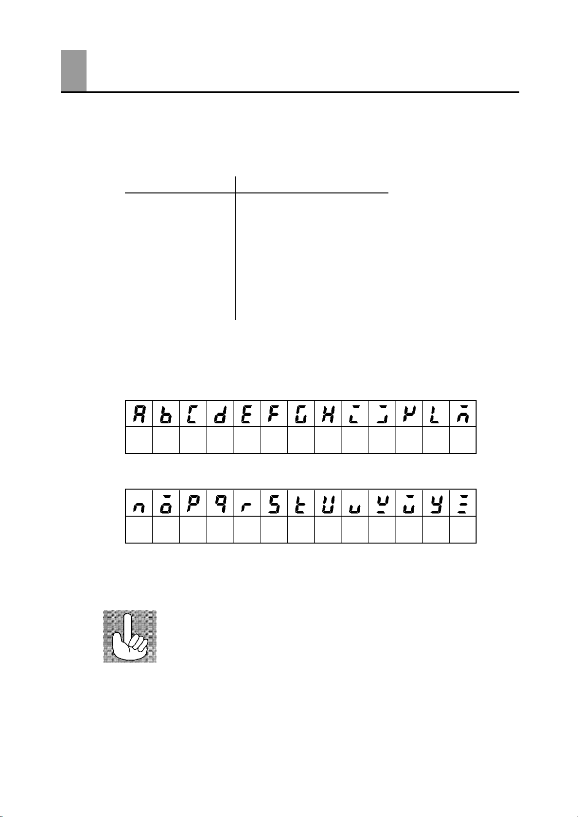
JHow to Read Display Symbols
The following tables show the correspondence between the symbols displayed on the displays
and alphabet characters.
ABCDEFGH I JKLM
NOPQRSTUVWXYZ
J“Reference” mark
This mark indicates that extra, useful information follows, such as supplementary explanations and how to apply functions.
II
Page 4

JNotice:
OMRON products are manufactured for use according to proper procedures by a qualified
operator and only for the purposes described in this manual.
The following conventions are used to indicate and classify precautions in this manual. Always heed the information provided with them. Failure to heed precautions can result in injury to people or damage to the product.
DANGER
WARNING
Caution
Indicates information that, if not heeded, is likely to result in loss of
life or serious injury.
Indicates information that, if not heeded, could possibly result in
loss of life or serious injury.
Indicates information that, if not heeded, could result in relatively
serious or minor injury, damage to the product, or faulty operation.
III
Page 5

JHow this Manual is Organized
Purpose Title Description
D Learning about the gen-
eral features of the E5EK
Chapter 1 Introduction This chapter describes the fea-
tures of the E5EK, names of
parts, and typical functions.
D Setting up the E5EK
D Basic E5EK operations
D Applied E5EK operations
D Using a Position-propor-
tional Type Controller
D Communications with a
host computer
Chapter 2 Preparations This chapter describes the
operations that you must carry
out (e.g. installation, wiring and
switch settings) before you can
use the E5EK.
Chapter 3 Basic Operation
Chapter 5 Parameters
Chapter 4 Applied Operation
Chapter 5 Parameters
Chapter 4 Applied Operation/4.1 Selecting the Control Method
Chapter 6 Using the Communications Function
These chapters describe how to
use the front panel keys and
how to view the display when
setting the parameters of the
major functions for the E5EK.
These chapters describe the
important functions of the
E5EK and how to use the
parameters for making full use
of the E5EK.
This chapter describes the functions related specifically to position-proportional type controllers.
This chapter mainly describes
the commun ications commands,
and gives program examples.
D Calibration
D Troubleshooting
IV
Chapter 7 Calibration This chapter describes how the
user should calibrate the E5EK.
Chapter 8 Troubleshooting This chapter describes what to
do if any problems occur.
Page 6

PayAttention to the Following when Installing
this Controller
F If you remove the controller from its case, never touch nor apply shock to the elec-
tronic parts inside.
F Do not cover the area around the E5EK. (Ensure sufficient space around the control-
ler to allow heat radiation.)
F Use a voltage (AC100-240V
scribed voltage level must be attained within two seconds.
F When wiring input or output lines to your controller, keep the following points in
mind to reduce the influence from inductive noise:
• Allow adequate space between the high voltage/current power lines and the input/
output lines.
• Avoid parallel or common wiring with high voltage sources and power lines carrying
large currents.
• Using separating pipes, duct, and shielded line is also useful in protecting the controller, and its lines form inductive noise.
F Allow as much space as possible between the controller and devices that generate a
powerful, high frequency (high-frequency welders, high-frequency sewing machines,
and so forth) or surge. T hese devices may cause malfunctions.
F If there is a large power-generating peripheral device and any of its lines, attach a
surge suppressor or noise filter to the device to stop the noise affecting the controller
system. In particular, motors, transformers, solenoids and magnetic coils have an
inductance component, and therefore can generate very strong noises.
F When mounting a noise filter, be sure to first check the filter’s voltage and current
capacity, then mount the filter as close as possible to the controller.
F Do not use the controller in places where icing, condensation, dust, corrosive gas
(especially sulfurized gas or ammonia gas), shock, vibration, splashing liquid, or oil
atmosphere occur. Also, avoid places where the controller can be subjected to intense
heat radiation (like from a furnace) or sudden temperature changes.
or AC/DC24V at 50 to 60 Hz). At power ON, the pre-
F Ambient temperature must be kept between -10_Cto55_C. Ambient humidity must
be kept between 35%RH to 85%RH (with no icing or condensation). If the controller
is installed inside a control board, the ambient temperature must be kept under
55_C, including the temperature around the controller. If the controller is subjected
to heat radiation, use a fan to cool the surface of the controller to under 55_C.
F Store the controller at an ambient temperature between -25_Cto65_C. The amb ient
humidity must be between 35%RH to 85%RH (with no icing or condensation).
F Never place heavy objects on, or apply pressure to the controller that may cause it to
deform an d deterioration during use or storage.
F Avoid using the controller in places near a radio, television set, or wireless installa-
tion. These devices can cause radio disturbances which adversely affect the performance of the controller.
V
Page 7

Table of Contents
Preface I......................................
Conventions Used in This Manual II...............
Pay Attention to the Following when Installing
this Controller V.................................
CHAPTER 1 INTRODUCTION 1--1...........................
This chapter introduces the E5EK. First-time users should read this chapter without fail.
For details on how to use the controller and parameter settings, see Chapters 2
onwards.
1.1 Names of parts 1--2..........................................
1.2 Input and Output 1--4.........................................
1.3 Parameters and Menus 1--7...................................
1.4 About the Communications Function 1--10.......................
1.5 About Calibration 1--11........................................
CHAPTER 2 PREPARATIONS 2--1...........................
This chapter describes the operations you should carry out before turning the
E5EK ON.
2.1 Setting up 2--2...............................................
2.2 Installation 2--5..............................................
2.3 Wiring Terminals 2--8.........................................
CHAPTER 3 BASIC OPERATION 3-- 1........................
This chapter describes an actual example for understanding the basic operation
of the E5EK.
3.1 Convention Used in this Chapter 3--2...........................
3.2 Setting Input Specifications 3--4...............................
3.3 Setting Output Specifications 3--6..............................
3.4 Setting Alarm Type 3--9.......................................
3.5 Protect Mode 3--12............................................
3.6 Starting and Stopping Operation 3--13...........................
3.7 Adjusting Control Operation 3--14...............................
CHAPTER 4 APPLIED OPERATION 4-- 1......................
This chapter describes each of the parameters required for making full use of the
features of the E5EK. Read this chapter while referring to the parameter descriptions in chapter 5.
4.1 Selecting the Control Method 4--2..............................
4.2 Operating Condition Restrictions 4--5...........................
4.3 How to Use Event Input 4--8..................................
4.4 How to Use the Remote SP 4--11...............................
4.5 How to Use the Heater Burnout Alarm 4--13......................
4.6 LBA 4--15....................................................
4.7 How to Use Transfer Output 4--17...............................
Page 8

CHAPTER 5 PARAMETERS 5-- 1.............................
This chapter describes the parameters of the E5EK. Use this chapter as a reference guide.
Protect Mode 5--3................................................
Manual Mode 5--5................................................
Level 0 Mode 5--6................................................
Level 1 Mode 5--10................................................
Level 2 Mode 5--18................................................
Setup Mode 5--25.................................................
Expansion Mode 5--32.............................................
Option Mode 5--37.................................................
Calibration Mode 5--46.............................................
CHAPTER 6 USING THE COMMUNICATIONS FUNCTION 6--1..
This chapter mainly describes communications with a host computer and communications commands.
6.1 Outline of the Communications Function 6--2....................
6.2 Preparing for Communications 6--3............................
6.3 Command Configuration 6--5..................................
6.4 Commands and Responses 6--6...............................
6.5 How to Read Communications Error Information 6--12.............
6.6 Program Example 6--14.......................................
CHAPTER 7 CALIBRATION 7-- 1.............................
This chapter describes procedures for each calibration operation.
Read this chapter only when the controller must be calibrated.
7.1 Structure of Parameters 7--2..................................
7.2 Calibrating Thermocouple 7--4.................................
7.3 Calibrating Platinum Resistance T hermometer 7--7..............
7.4 Calibrating Current Input 7--9..................................
7.5 Calibrating Voltage Input 7--10..................................
7.6 Checking Indication Accuracy 7--12.............................
CHAPTER 8 TROUBLESHOOTING 8-- 1......................
This chapter describes how to find out and remedy the cause if the E5EK does
not function properly.
8.1 Initial Checks 8--2............................................
8.2 How to Use the Error Display 8--3..............................
8.3 How to Use Error Output 8--5..................................
8.4 Checking Operation Restrictions 8--6...........................
APPENDIX
SPECIFICATIONS A--2........................
ABOUT CURRENT TRANSFORMER (CT) A--5...
CONTROL BLOCK DIAGRAM A--6..............
SETTING LIST A--8...........................
MODEL LIST A--11.............................
PARAMETER OPERATIONS LIST A--12..........
FUZZY SELF-TUNING A--14....................
XFORMAT A--17...............................
ASCII CODE LIST A--20........................
INDEX
REVISION HISTORY
Page 9

CHAPTER1
CHAPTER 1
INTRODUCTION
This chapter introduces the E5EK. First-time users should read this
chapter without fail.
For details on how to use the controller and parameter settings, see
Chapters 2 onwards.
CHAPTER 1 INTRODUCTION
1.1 Names of parts 1-2........................
Main parts 1-2............................
Front panel 1-2...........................
About the displays 1-3.....................
How to use keys 1-3.......................
1.2 Input and Output 1-4......................
Input 1-4.................................
Output 1-5................................
1.3 P arameters and Menus 1-7.................
Parameter types 1-7.......................
Selecting modes 1-8........................
Selecting parameters 1-9...................
Fixing settings 1-9.........................
1.4 About the Communications Function 1-10....
1.5 About Calibration 1-11......................
1-- 1
Page 10
CHAPTER 1 INTRODUCTION
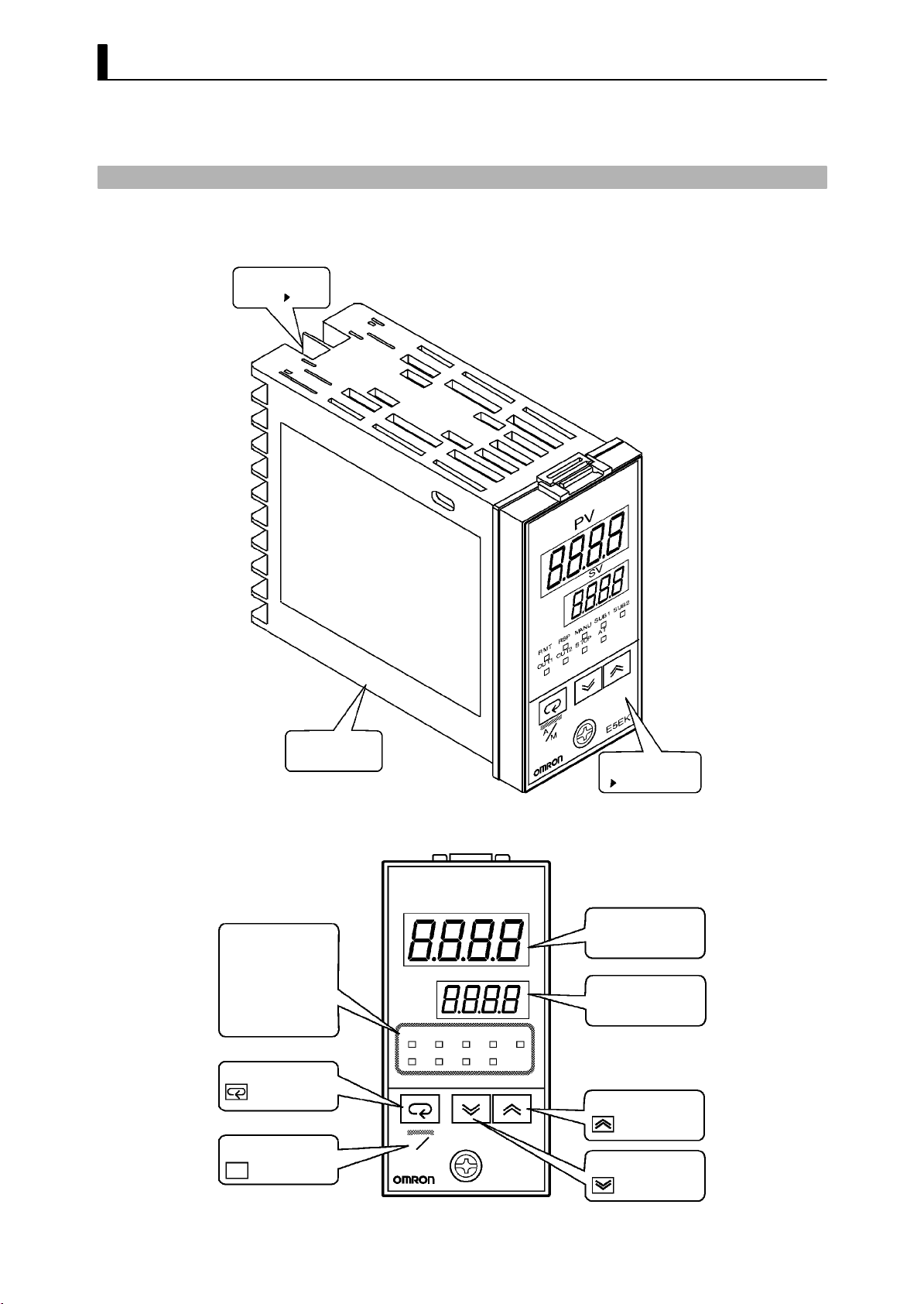
1.1 Names of parts
JMain parts
Terminals
P2-6
JFront panel
Operation indicators
OUT1
SUB1
MANU
STOP
RMT
RST
AT
Display key
A/M key
A/M
Rear case
OUT2
SUB2
RMT
RSP SUB1
OUT1 OUT2
A
M
PV
MANU
STOP
Front panel
This page
No.1 display
SV
No.2 display
SUB2
AT
Up k ey
Down ke y
E5EK
1-- 2
Page 11

JAbout the displays
1.1 Names of parts
F No.1 display
F No.2 display
F Operation indica-
tors
JHow to use keys
Displays the p rocess value or parameter symbols.
Displays the set point, manipulated variable or parameter settings.
• OUT1 : Lit when the pulse output function assigned to “control
output 1” is ON.
• OUT2 : Lit when the pulse output function assigned to “control
out- put 2” is ON.
• SUB1 : Lit when the output function assigned to “auxiliary output
1” is ON.
• SUB2 : Lit when the output function assigned to “auxiliary
output 2” is ON.
• MANU : Lit in the manual operation mode.
• STOP : Lit when operation has stopped.
• RMT : Lit during remote operation.
• RSP : Lit during remote SP operation.
• AT : Flashes during auto-tuning.
The following describes basic key operations.
A/M
F key
F key
F key
Each press of this key switches between the auto and manual operations.
The functions of this key change according to how long it i s pressed. If
the key is pressed for less than one second, the parameters are switched.
If the key is pressed for one second or more, the menu display appears.
In key operations from here on, “press the key” refers to pressing the
key for less than one second.
For details on parameter switching and menu display items, see page
1-8.
Each press of the
on the No.2 display, while each press of the
returns the values or settings on the No.2 disp lay.
Functions vary, for example, when the
neously with the display key, or a key is held down continuously. For
details, see page 1-8. Also, chapters 3 and 4 describe examples using
various key combinations.
key increments or advances the values or settings
key decrements or
A/M
key is held down simulta -
1-- 3
Page 12
CHAPTER 1 INTRODUCTION
1.2 Input and Output
JInput
Temperature input
Voltage input
Current input
CT input
Potentiometer
Remote SP input
Event input
Controller
Control output
(heat)
Control output
(cool)
Alarm 1
Alarm 2
Alarm 3
HBA
LBA
Error 1
Error 2
Error 3
Control output 1
Control output 2
Auxiliary output 1
Auxiliary output 2
Transfer output
The E5EK supports following inputs: temperature input, current input,
voltage input, CT input/Potentiometer, remote SP input and event
input.
F Temperature input/Voltage input/Current input
• Only one of temperature input, voltage input and current input can
be selected and connected to the controller. The above figure shows
temperature input connected to the controller.
• The following input sensors can be connected for temperature input:
Thermocouple:K,J,T,E,L,U,N,R,S,B,W,PLII
Platinum resistance thermometer: JPt100, Pt100
• The following currents can be connected for current input:
4to20mA,0to20mA
• The following voltages can be connected for voltage input:
1to5VDC,0to5VDC,0to10VDC
F CT input/Poten-
tiometer
F Remote SP input
• Connect CT input when using the HBA (heater burnout alarm) func-
tion on a standard type controller (E5EK-AA2).
• Connect the potentiometer when monitoring the valve opening on a
position-proportional type controller (E5EK-PRR2). However, note
that the potentiometer cannot be used simultaneously with remote
SP input.
• Remote SP input cannot be used simultaneously with potentiometer.
• When the remote SP function is enabled, inputs within the range 4 to
20 mA are used as the remote SP.
1-- 4
Page 13

1.2 Input and Output
F Event input
JOutput
When using event input, add on the input unit (E53-CKB).
You can select from the following four event inputs:
Multi-SP
Run/Stop
Auto/Manual
SP mode
The E5EK supports the following five outputs.
Control output 1
Control output 2
Auxiliary output 1
Auxiliary output 2
Transfer output
When using control outputs 1 and 2, set the output unit (sold separately). Nine output units are available to suit the output circuit configuration.
When using transfer output, add on the communication unit
(E53-AKF).
Note: The output functions of the E5EK do not operate for five seconds
after the E5EK is turned ON.
F Output assign-
ments
The E5EK supports the following ten output functions.
Control output (heat)
Control output (cool)
Alarms 1 to 3
HBA
LBA
Error 1 (input error)
Error 2 (A/D converter error)
Error 3 (RSP input error)
Assign these output functions to control output 1, control output 2,
auxiliary output 1, and auxiliary output 2.
However, note that as control output 1 is used as the open output and
control output 2 is used as close output on a position-proportional type
controller (E5EK-PRR2), control outputs 1 and 2 cannot be used as
assignment destinations. Also, of the output functions, control output
(heat), control output (cool), HBA and LBA are disabled.
On a standard type controller, there are restrictions on how assignment
destinations (control output 1, control output 2, auxiliary output 1, and
auxiliary output 2) can be used. For details, see 3.3 Setting Output
Specifications.
In the example on the previous p age, “control output (heat)” is assigned
to “control output 1”, “alarm 1” is assigned to “control output 2”, and
“alarm 2” is assigned to “auxiliary output 1”. Accordingly, the configuration is such that heating control output is connected to control output
1, and alarm output is connected to control output 2 and auxiliary output 1.
1-- 5
Page 14

CHAPTER 1 INTRODUCTION
Control outputs 1 and 2 are used depending on the differences in control method as follows.
F Transfer output
Control Method
Standard control E5EK-AA2 AC100-240
E5EK-AA2 AC/DC24
Heating and cooling
control
Position-proportional
control
The E5EK supports the following six transfer outputs.
Set point
Set point during SP ramp
Process value
Heating side manipulated variable
Cooling side manipulated variable
Valve opening
However, note that heating/cooling side manipulated variables can be
output only standard type controllers, and valve opening can be output
on position-proportional type controllers
These transfer outputs can be output after being scaled. Setting of an
upper limit value smaller than the lower limit value is allowed, so
reverse scaling can also be carried out.
E5EK-AA2 AC100-240
E5EK-AA2 AC/DC24
E5EK-PRR2 AC100-240
E5EK-PRR2 AC/DC24
Model
Control Output 1/
Control Output 2
Control output (heat) /
Alarm, etc.,
Control output (heat) /
Control output (cool)
Open/Close
1-- 6
Page 15

1.3 Parameters and Menus
1.3 Parameters and Menus
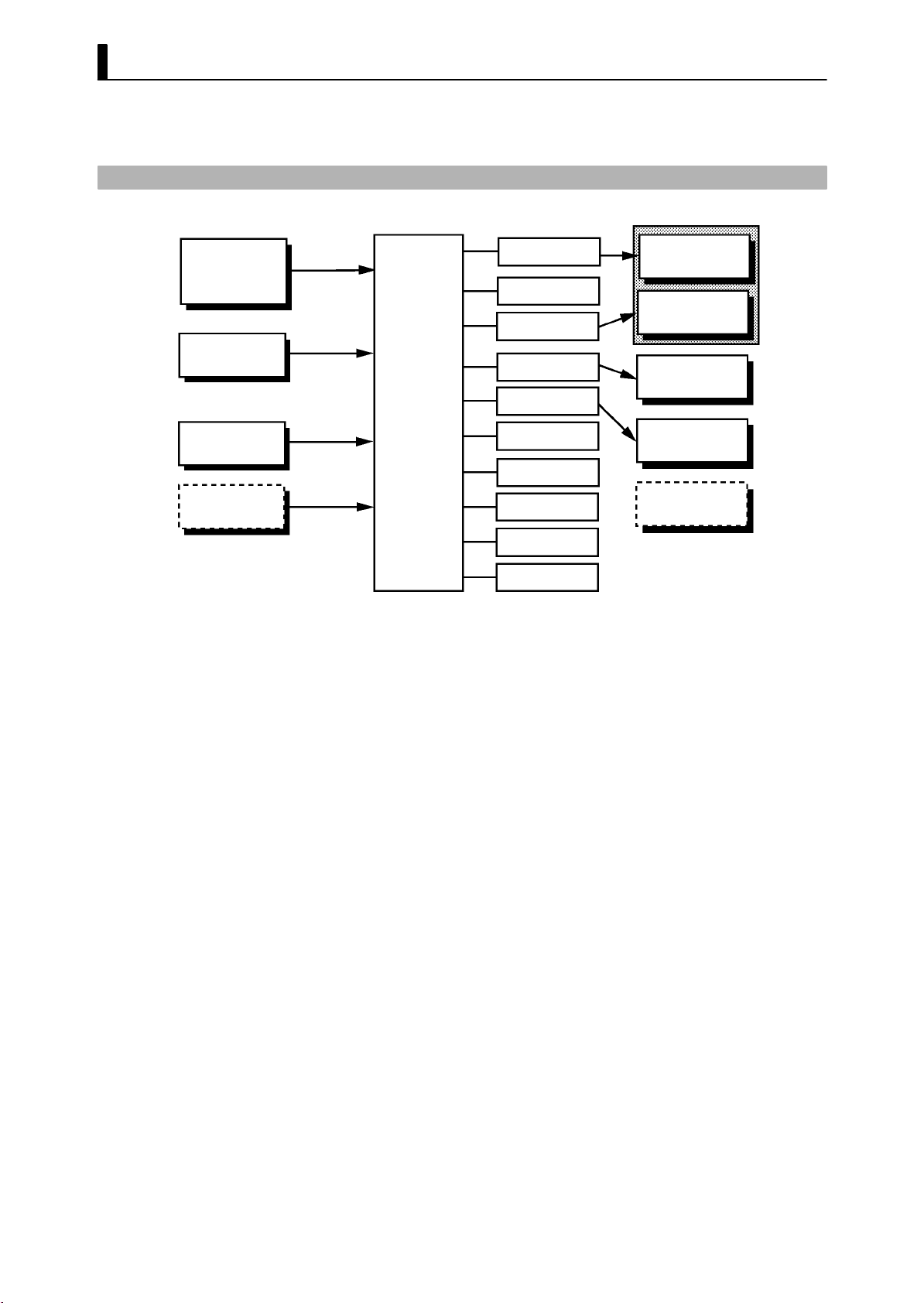
JParameter types
F Protect mode
F Manual mode
F Level 0 mode
E5EK parameters are distributed between the following nine modes.
Protect mode
Manual mode
Level 0 mode
Level 1 mode
Level 2 mode
Setup mode
Expansion mode
Option mode
Calibration mode
The settings of parameters in each of seven modes (excluding the protect mode and manual mode) can be checked and modified by selection
on the menu display.
This mode is used to limit use of the menu and
function is for preventing unwanted modification of parameters and
switching between the auto and manual operation.
In this mode, the controller can be switched manual operation. The
manipulated variable can be manipulated manually only in this mode.
Set the controller to this mode during normal operation. In this mode,
you may change the set point during operation, and stop and start operation. You can also monitor (not change) the process value, ramp SP
and manipulated variable.
A/M
keys. The protect
F Level 1 mode
F Level 2 mode
F Setup mode
F Expansion mode
F Option mode
This is the main mode for adjusting control. In this mode, you can
execute AT (auto-tuning), and set alarm values, the control period and
PID parameters.
This is the auxiliary mode for adjusting control. In this mode, you can
set the parameters for limiting the manipulated variable, switch
between the remote and local modes, switch between the SP modes, and
set the loop break alarm (LBA), alarm hysteresis and the digital filter
value of inputs.
This is the mode for setting the b asic specifications. In this mode, you
can set parameters that must be checked or set before operation such as
the input type, scaling, output assignments and direct/reverse operation.
This is the mode for setting expanded functions. In this mode, you can
set ST (self-tuning), SP setting limiter, selection of advanced PID or
ON/OFF control, specification of the standby sequence resetting
method, time for automatic return to the monitoring display.
This is the mode for setting option functions. You can select this mode
only when the option unit is set in the controller. In this mode, you can
1-- 7
Page 16
CHAPTER 1 INTRODUCTION
set the communications conditions, transfer output and event input
parameters to match the type of option unit set in the controller. Heater
burnout latch function, position-proportional travel time and remote
SP scaling parameters are also located in this mode.
F Calibration mode
JSelecting modes
This mode is provided so that the user can calibrate inputs and transfer
output.
When calibrating input, the selected input type is calibrated. Whereas,
transfer output can be calibrated only when the communications unit
(E53-AKF) is set in the controller.
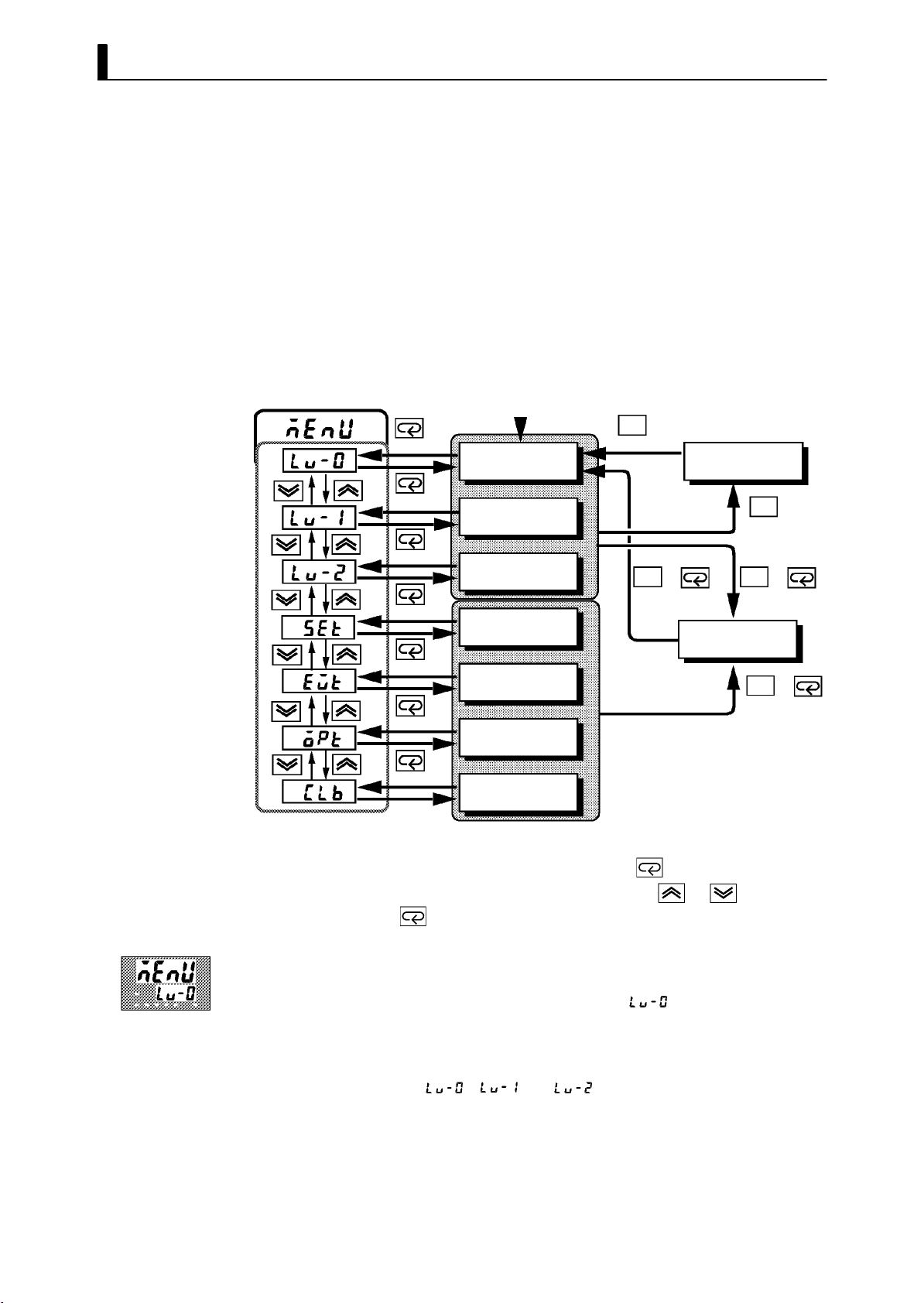
The following diagram shows the order in which modes are selected.
Power ON
1 second min.
Level 0 mode
1 second min.
Level 1 mode
1 second min.
Level 2 mode
1 second min.
Setup mode
1 second min.
Expansion mode
1 second min.
Option mode
A/M
1secondmin.
Manual mode
A/M
++
1 second min. 1 second min.
Protect mode
A/M
1secondmin.
A/M
A/M
+
1secondmin.
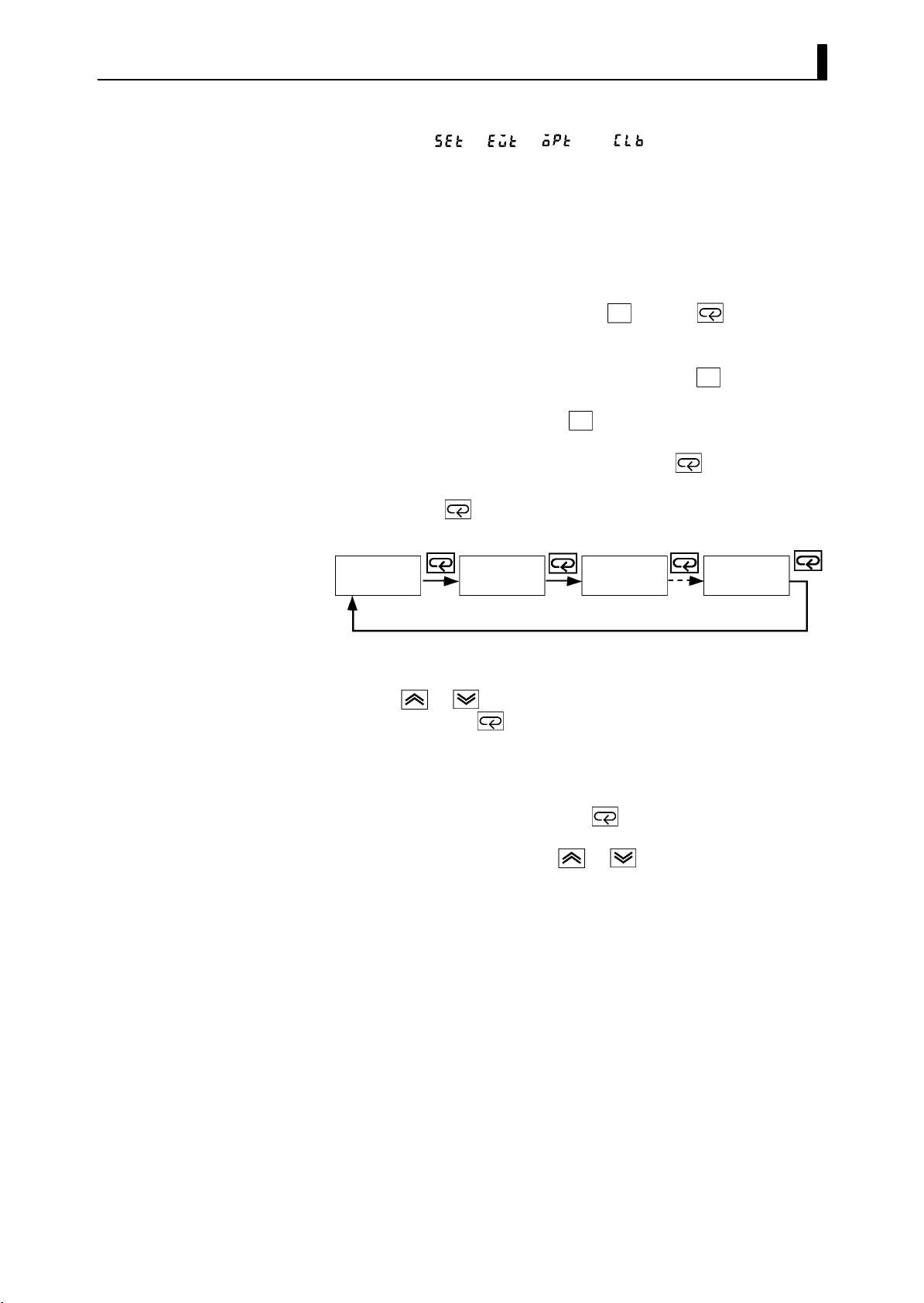
F Menu display
F Level 0 to 2
modes
1 second min.
Calibration mode
• To select the menu display in any of the above modes (excluding the
protect mode and manual mode), press the
mum. If you select the desired mode using the
press the
key, the top parameter in the specified mode is dis-
key for 1 second mini-
or keys and
played.
• When you have selected the menu display, the previous mode is
selected. For example, if you selected the menu display while in the
level 0 mode, the No.2 display changes to [
] as shown on the left.
• Protected modes cannot be selected. Also, the menu display does not
appear when modes are protected up to the level 1 mode.
• If you select [
][ ]or[ ] in the menu display , the level 0,
level 1 and level 2 modes, respectively, are selected.
• These modes are selected with control still continuing.
1-- 8
Page 17
1.3 Parameters and Menus
F Setup mode
F Expansion mode
F Option mode
F Calibration mode
F Protect mode
F Manual mode
JSelecting
parameters
• If you select [
the setup, expansion, option and calibration modes, respectively, are
selected.
• When these modes are selected, the control is reset. So, control out-
puts and auxiliary output are turned OFF. When another mode is
selected while in these modes, reset is canceled.
• To set the controller to the protect mode or to return to the level 0
mode from the protect mode, press the
cond minimum simultaneously.
• To set the controller to the manual mode, press the
cond minimum in the level 0 to 2 mode. To return to the level 0 mode
from the manual mode, press the
• When not in the manual mode, each press of the
parameter.
• If you press the
turns to the first parameter.
Parameter
1
][ ][ ]or[ ]inthe menudisplay,
A/M
key and key for 1 se-
A/M key for 1 se-
A/M key for 1 second minimum.
key switches the
key when at the final parameter, the display re-
Parameter
2
Parameter
3
Parameter
n
JFixing settings
• When you have changed a parameter setting, specify the parameter
using the
seconds or press the
• When another mode is selected, the content of the parameters before
the mode was selected is fixed.
• When turning the power OFF, you must first fix the settings and
parameter contents (by pressing the
mode). The settings and parameter contents are sometimes not
changed by merely pressing the
or keys, and either leave the setting for at least two
key. This fixes the setting.
key or selecting another
or keys.
1-- 9
Page 18

CHAPTER 1 INTRODUCTION
1.4 About the Communications Function
The E5EK can be provided with a communications function that allows
you to check and set controller parameters from a host computer. If the
communications function is required, add on the communications unit.
For details on the communications function, refer to Chapter 6.
F RS-232C
F RS-422
F RS-485
When using the communications function on the RS-232C interface,
add on the communications unit (E53-AK01).
When using the communications function on the RS-422 interface, add
on the communications unit (E53-AK02).
When using the communications function on the RS-485 interface, add
on the communications unit (E53-AK03).
1-- 10
Page 19

1.5 About Calibration
The E5EK controller is calibrated before shipment from the factory. So,
the user need not calibrate the E5EK controller during regular use.
However, if the E5EK controller must be calibrated by the user, use the
parameters provided for user to calibrate temp erature input, analog
input (voltage, current) and transfer output.
Also, note that calibration data is updated to the latest value each time
the E5EK controller is calibrated. Calibration data set before shipment
from the factory cannot be returned to after calibration by the user.
1.5 About Calibration
F Calibrating
inputs
F Calibrating trans-
fer output
F Registering cal-
ibration data
The input type selected in the parameter is the item to be calibrated.
The E5EK is provided with the following four calibration parameters.
• Thermocouple
• Platinum resistance thermometer
• Current input
• Voltage input
Two parameters are provided for thermocouple and voltage input.
Transfer output can be calibrated when the communications unit
(E53-AKF) is added on.
When calibrating each item, the calibration data is temporarily registered. This data can be registered as final calibration data only when all
items have been newly calibrated. So, all items must be temporarily
registered when calibrating the E5EK controller.
When registering data, information regarding whether or not calibration has been carried out is also registered.
To calibrate these items, the user must prepare separate measuring
devices and equipment. For details on handling these measuring devices
and equipment, refer to the respective manuals.
For details, see chapter 7 Calibration.
1-- 11
Page 20

CHAPTER 1 INTRODUCTION
1-- 12
Page 21

CHAPTER2
CHAPTER 2
PREPARATIONS
This chapter describes the operations you should carry out before
turning the E5EK ON.
CHAPTER 2 PREPARATIONS
2.1 Setting up 2-2.............................
Draw-out 2-2..............................
Setting up the output unit 2-3..............
Setting up the option unit 2-4...............
2.2 Installation 2-5............................
Dimensions 2-5............................
Panel cutout 2-5...........................
Mounting 2-6.............................
Setting up the terminal covers 2-7...........
2.3 Wiring Terminals 2-8......................
Terminal arrangement 2-8.................
Precautions when wiring 2-8...............
Wiring 2-8................................
2-- 1
Page 22
CHAPTER 2 PREPARATIONS
2.1 Setting up
• On a standard type controller, set up the output units for control out-
puts 1 and 2 before mounting the controller.
• On a position-proportional type controller, the relay output unit is
already set. So, this setup operation unnecessary. (Do not replace with
other output units.)
• When setting up the output units, draw out the internal mechanism
from the housing and insert the output units into the sockets for control outputs 1 and 2.
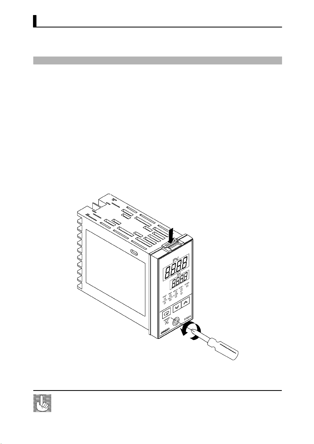
JDraw-out
When drawing out the internal mechanism from the housing, prepare a
phillips screwdriver matched to the size of the screw on the lower part
of the front panel.
(1) Press down on the hook on the top of the front panel and turn the
phillips screwdriver to the left to loosen the screw on the lower part
of the front panel.
2-- 2
Fixing Screw for
Front Panel
(2) Draw out the internal mechanism towards you holding both sides
of the front panel.
Tighten this screw by a torque of 0.3 to 0.5 N⋅m, or approx. 3 to 5 kgf⋅cm.
Page 23
JSetting up the output unit
2.1 Setting up
F Before setu p
F Procedure
• Check the type of the output unit you are about to set up.
• For details on types of output unit and main specifications, see page
2-9.
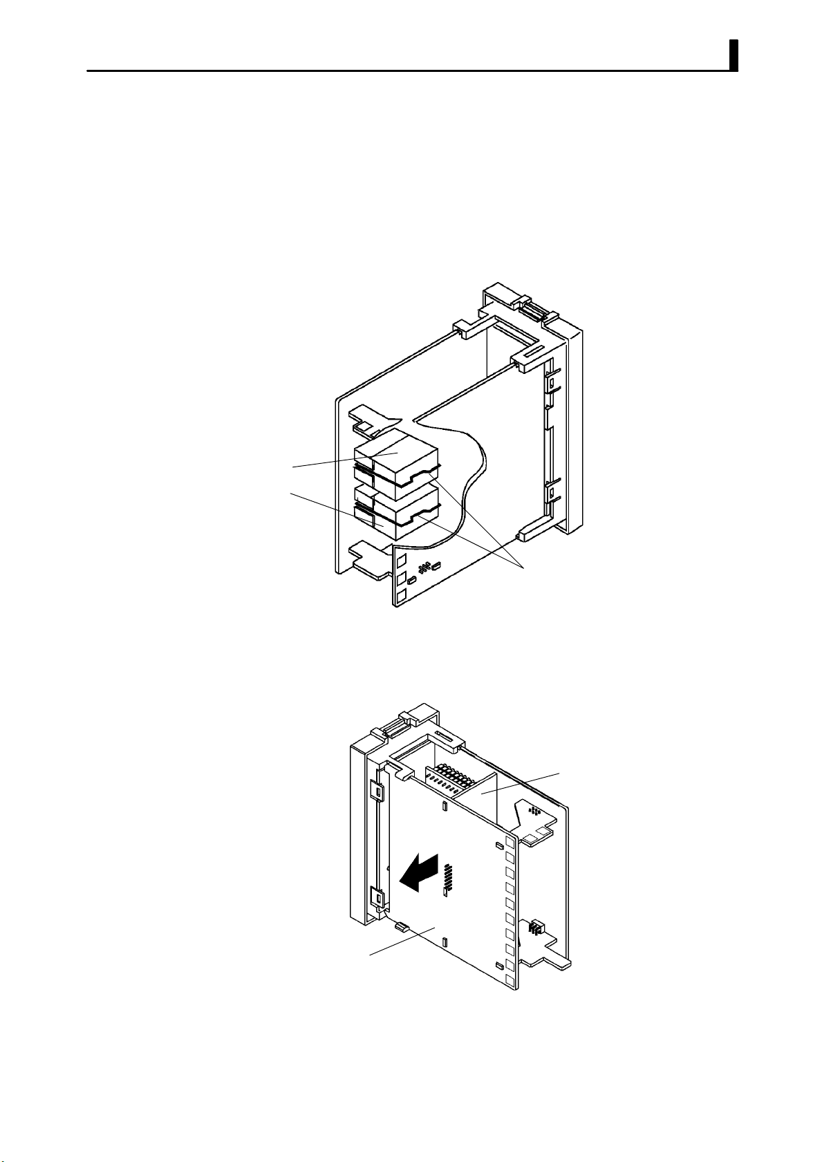
(1) Check the positions of the sockets you are about to insert the out-
put units into as shown in the following diagram.
OUT1
OUT2
Bracket
(2) Remove the power board in the direction of the arrow shown in the
figure. The power board is connected to the control board b y a center connector. Remove this connector taking care not to bend the
connector pins.
Control board
Power board
(3) Insert the output unit for control output 1 into the socket “OUT1”
and the output unit for control output 2 into the socket “OUT2”.
(4) Fasten the output units with the bracket (accessory).
(5) Return the power board to its original position.
2-- 3
Page 24
CHAPTER 2 PREPARATIONS
JSetting up the option unit
F Before setu p
F Procedure
• Check the type of the option unit you are about to set up.
• For details on types of option unit and main specifications, see Appen-
dix, Model List (page A -11) and Appendix, Option Unit Ratings and
Characteristics (p age A-4).
• For details on the relationship between units and terminals, see page
2-8.
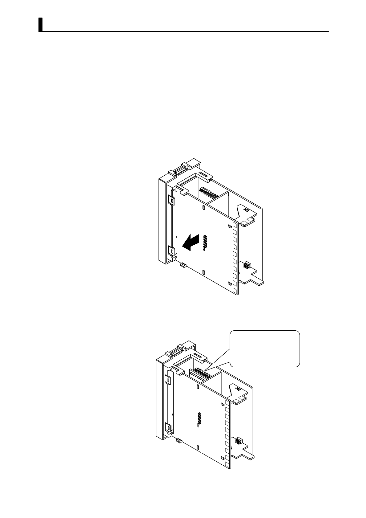
(1) Remove the power board and option boards in the order shown in
the following diagram.
2
1
(2) Insert the option unit into the socket for option 1. The following
diagram shows the relationship between option unit and mounting
position.
Option 1
E53--AKB: Event inputs 1/2
E53--AK01: RS --232C
E53--AK02: RS --422
E53--AK03: RS --485
E53--AKF: Transfer output
2-- 4
(3) Mount the option board and the power board in the order shown.
Page 25
2.2 Installation
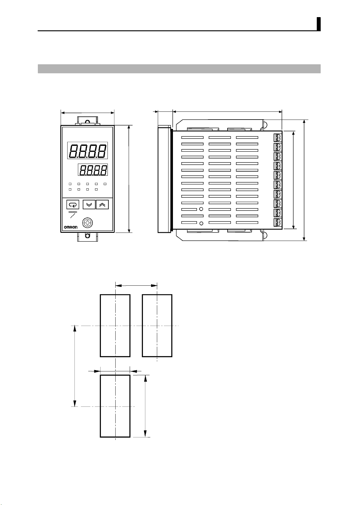
JDimensions
48
PV
SV
MANU
RMT
OUT1 OUT2
STOP
SUB2RSP SUB1
AT
96
13.5 100
2.2 Installation
91
112
A
M
JPanel cutout
Unit (mm)
120 mm min
E5EK
45
• Thewidthoftherearcaseis44mm.
60 mm min
• R ecommended panel thickness is 1 to 8
mm.
• Maintain the specified vertical and horizontal mounting space between each
controller.
Controllers must not be closely mounted
vertically or horizontally.
+0.6
0
92
+0.8
0
2-- 5
Page 26
CHAPTER 2 PREPARATIONS
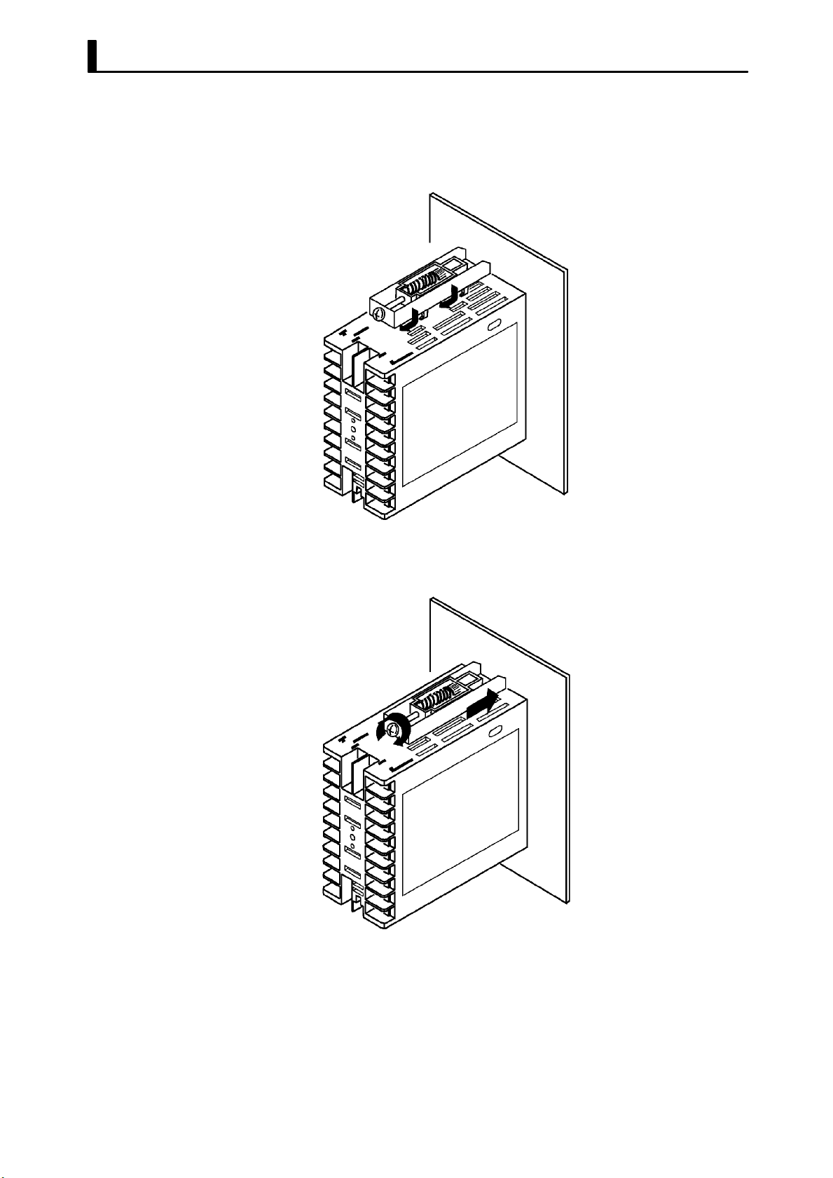
JMounting
(1) Insert the E5EK controller into the mounting hole in the panel.
(2) Fit the mounting bracket (accessory) into the fixing slots on the top
and bottom of the rear case.
(3) Tighten the mounting bracket screws alternately a little at a time
until the ratchet start to slide.
2-- 6
Page 27
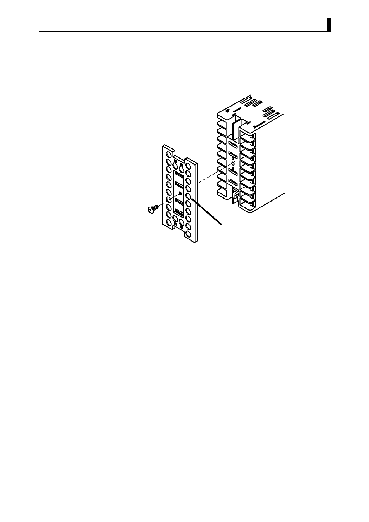
F Setting up the terminal covers
• Fasten the terminal cover (E53-COV08) to protect terminals.
• E5EK-VV2-500 controller is provided with terminal covers.
• Fasten the terminal cover as follows by using the snap pins.
2.2 Installation
E5EK
E53-COV08
• To remove the terminal cover, pull the edges of the snap pins.
2-- 7
Page 28
CHAPTER 2 PREPARATIONS
2.3 Wiring Terminals
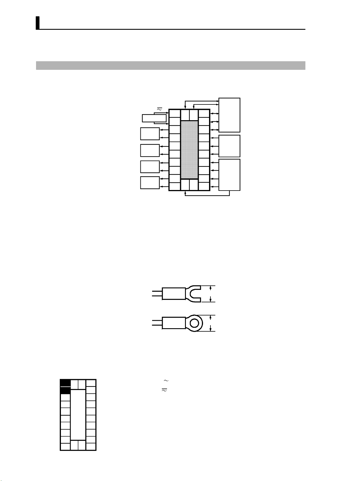
JTerminal arrangement
AC100-240V
(AC/DC24V )
SOURCE
OUT1
OUT2
SUB1
SUB2
~
10
9
8
7
6
5
4
3
2
1
21 22
23
20
19
18
17
16
15
14
13
12
11
EV1/2
TRSF
RS232C
RS422
RS485
RSP
CT
PTMR
TC
Pt
I
V
JPrecautions
when wiring
JWiring
F Power supply
10
21 22
9
8
7
6
5
4
3
2
23
1
20
19
18
17
16
15
14
13
12
11
TRSF : Transfer output
EV1/2 : Event inputs
PTMR : Potentiometer
• Use ducts to separate input leads and power lines in order to protect
the controller and its lines from external noise.
• We recommend using solderless terminals when wiring the controller.
• Ti ghten the terminal screws using a torque no greater than 0.78 N·m,
or 8 kgf·cm max. Take care not to tighten the terminal screws too
tightly.
• Use the following type of solderless terminals for M3.5 screws.
7.2mm max.
7.2mm max.
In the following wiring diagrams, the left side of the terminal Nos. indicates the inside of the controller
• Input power to terminal Nos. 9 and 10. Power spe cificat ions are as follows:
AC100-240V
(AC/DC24V
, 50/60Hz, 15VA
, 50/60Hz, 12VA 8W)
2-- 8
Page 29
2.3 Wiring Terminals
F Sensor input
10
9
8
7
6
5
4
3
2
1
21 22
23
20
19
18
17
16
15
14
13
12
11
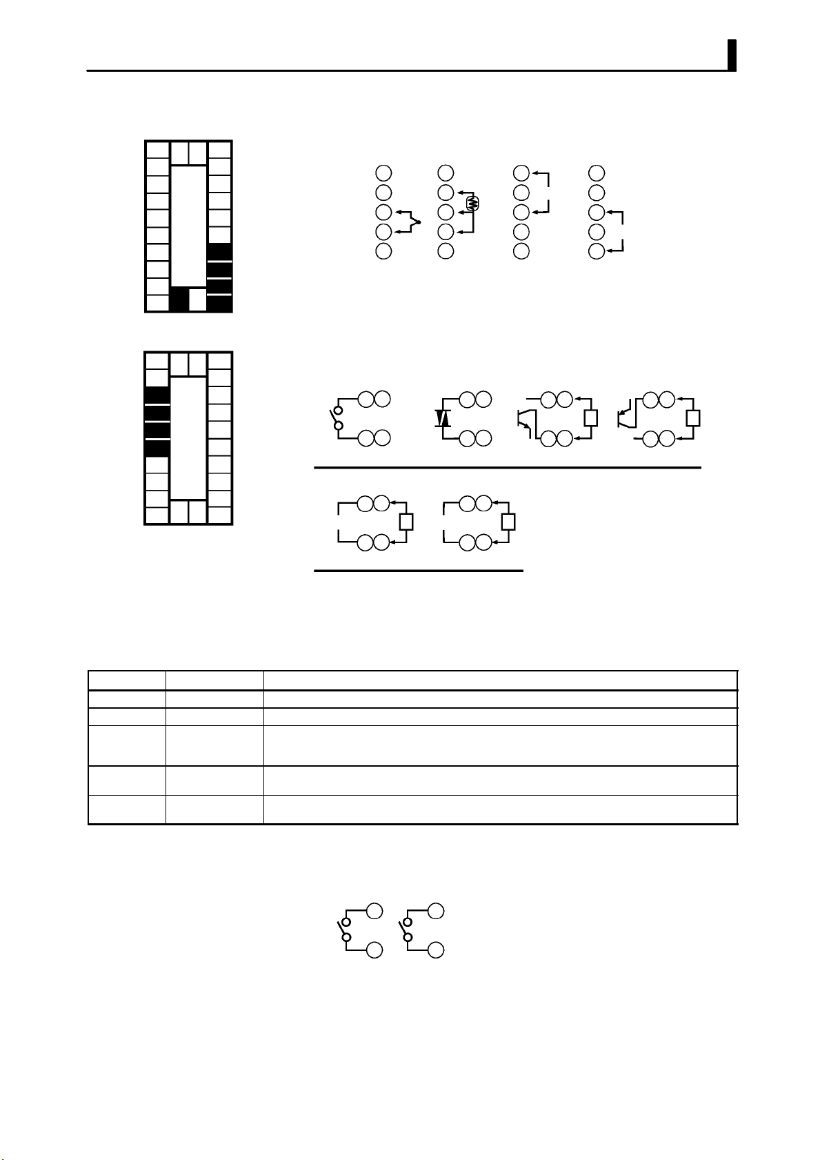
F Control output
10
9
8
7
6
5
4
3
2
1
21 22
23
20
19
18
17
16
15
14
13
12
11
• Connect the sensor input to terminal Nos. 11 to 14 and 33 as follows
according to the input type.
14
13
12
11
23
Thermocouple Platinum
--
+
resistance
thermometer
14
13
12
11
23
+
14
V
13
12
--
11
23
Voltage input Current input
14
13
12
11
23
mA
+
--
• Terminal Nos. 7 and 8 are for control output 1 (OUT1), and terminal
Nos. 5 and 6 are for control output 2 (OUT2). The following diagrams
show the available outpu t units and their internal equ a liz ing circuits.
86
75
NPN
E53-Q
E53-Q3
+
L
GND
--
86
75
Relay
E53-R E53-S E53-Q4
+
86
mA V
4to20mA/0to20mA
E53-C3
E53-C3D
LL
75
--
86
75
SSR PNP
86
75
0 to 10V/0 to 5V
E53-V34
E53-V35
+v
GND
+
--
+v
86
75
+
L
--
• With E53-VVV output units, about 2 V is output for one second after
the power is interrupted.
• The following table shows the specifications for each output unit.
Model Output Type Specifications
E53-R Relay 250 VAC, 5 A
E53-S SSR 75 to 250 VAC, 1 A
E53-Q
E53-Q3
E53-Q4
E53-C3
E53-C3D
E53-V34
E53-V35
Voltage (NPN)
Voltage (NPN)
Voltage (PNP)
4to20mA
0to20mA
0to10V
0to5V
NPN : 12 VDC, 40 mA (with short-circuit protection)
NPN : 24 VDC, 20 mA (with short-circuit protection)
PNP : 24 VDC, 20 mA (with short-circuit protection)
4 to 20 mA, Permissible load impedance: 600 Ω max., Resolution: Approx. 2600
0 to 20 mA, Permissible load impedance: 600 Ω max., Resolution: Approx. 2600
0 to 10 VDC, Permissible load impedance: 1 kΩ min., Resolution: Approx. 2600
0 to 5 VDC, Permissible load impedance: 1 kΩ min., Resolution: Approx. 2600
With E5EK-PRR2 controllers, relay output (250 VAC, 1 A) is fixed.
When replacing the output unit, use the E53-R. The following diagrams
show the relationship between terminals and open/close relay settings.
8
7
Open
6
5
Close
2-- 9
Page 30
CHAPTER 2 PREPARATIONS
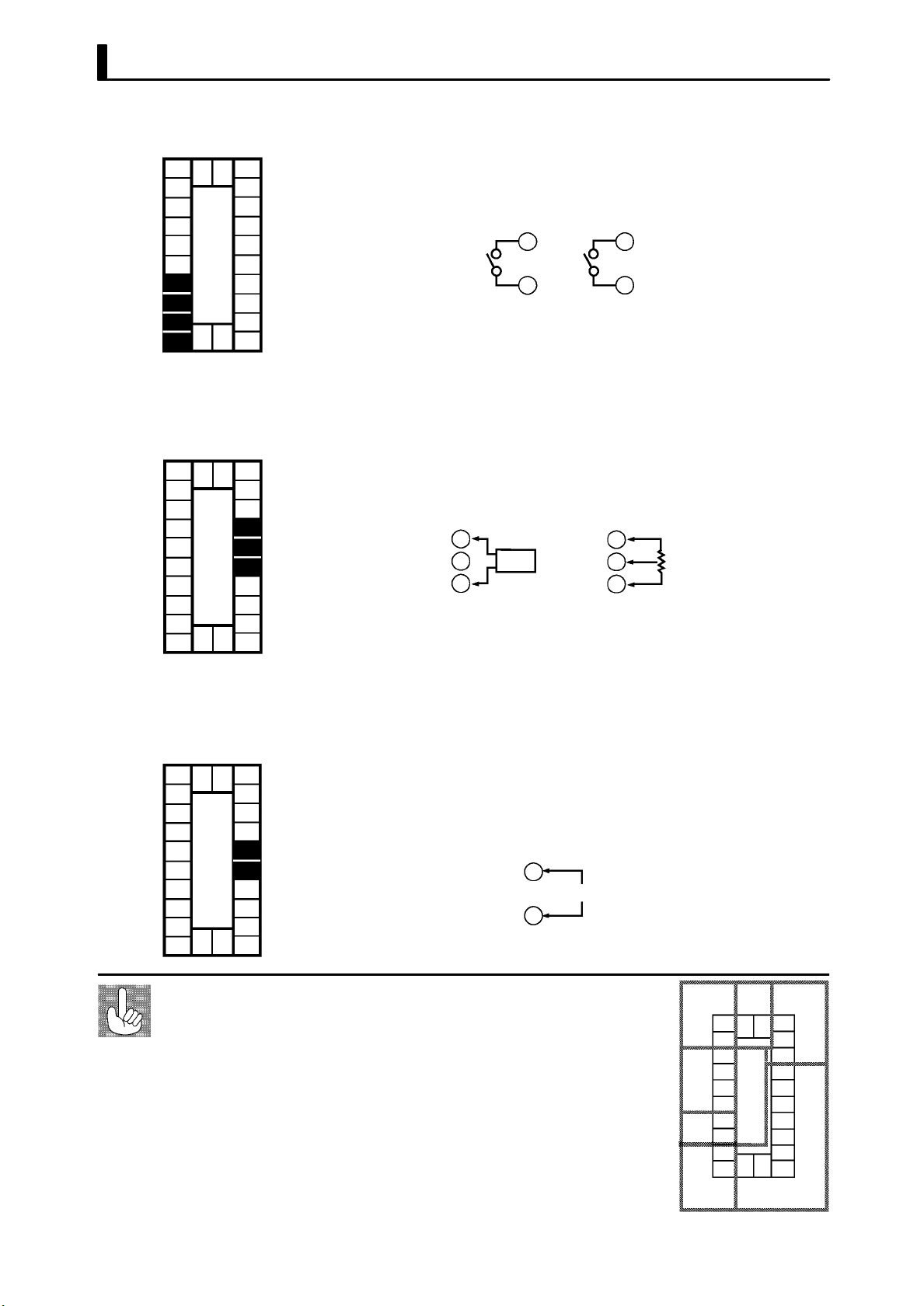
F Auxiliary output
10
9
8
7
6
5
4
3
2
1
21 22
23
20
19
18
17
16
15
14
13
12
11
F CT input/
Potentiometer
10
9
8
7
6
5
4
3
2
1
21 22
23
20
19
18
17
16
15
14
13
12
11
• Terminal Nos.3 and 4 are for auxiliary output 1 (SUB1) and terminal
Nos.1 and 2 are for auxiliary output 2 (SUB2).
• The internal equalizing circuits for the auxiliary outputs are as follows:
4
3
Auxiliary
output 1
2
1
Auxiliary
output 2
• Output specifications are as follows:
SPST-NO, AC250V, 3A
• When using the HBA function on the E5EK-AA2 controller, connect
CT input (CT) to terminal Nos.15 to 17. When monitoring the valve
opening on the E5EK-PRR2 controller, connect the potentiometer
(PTMR) to terminal Nos.15 to 17. Connect each of these inputs as follows:
17
16
15
CT input Potentiometer
CT
17
16
15
O
W
C
• For details on CT inputs, see Appendix, About current transformer.
• For details on the potentiometer, see the Instruction Manual for the
valve connected to the controller. The variable resistance range is 100
Ω to 2.5 kΩ.
F Remote SP input
10
9
8
7
6
5
4
3
2
1
About the power
blocks
21 22
23
20
19
18
17
16
15
14
13
12
11
• Connect an input (RSP) to be used as the remote SP to terminal
Nos.15 and 16. However, note that the remote SP can not be used on
the E5EK-PRR2 controller.
• Only 4 to 20 mA inputs can be connected. Connect the input as follows:
+
16
4to20mA
15
--
The E5EK has independent power supplies for each of
the terminal blocks shown on the right.
AB/CC
21 22
23
20
19
18
17
16
15
14
13
12
11
10
9
8
7
B
6
5
4
E
3
2
1
FD
2-- 10
Page 31

2.3 Wiring Terminals
F Event input
10
21 22
9
8
7
6
5
4
3
2
23
1
20
19
18
17
16
15
14
13
12
11
• Connect event inputs 1 and 2 (EV1/2) to terminal Nos.18 to 20. However, note that terminal Nos.18 to 20 cannot be used on controllers
having a communications function.
• Connect the event inputs as follows:
EV1
EV2
COM
Event input 1 and 2
19
18
+
--
+
20
• Use event inputs under the following conditions:
Contact input
ON: 1 kΩ max., OFF: 100 kΩ min.
No-contact input ON: residual voltage 1.5 V max.,
OFF: leakage current 0.1 mA max.
• Polarities during no-contact input are as follows:
+
20
EV1
19
18
+
--
EV2
COM
Event input 1 and 2
F Transfer output
F Communications
• Connect transfer output (TRSF) to terminal Nos. 21 and 22.
• The internal equalizing circuit for transfer output is as follows:
+
21
4to20mA L
22
--
• Transfer output specifications are as follows:4 to 20 mA,
Permissible load impedance: 600 Ω max.,
Resolution: Approx. 2600
• Terminal Nos.18 to 22 can be used only on controllers having a communications units (E53-AK01/02/03).
• For details on wiring, see Chapter 6, Using the Communications
Function.
2-- 11
Page 32

CHAPTER 2 PREPARATIONS
2-- 12
Page 33

CHAPTER3
CHAPTER 3
BASIC OPERATION
This chapter describes an actual example for understanding the basic
operation of the E5EK.
CHAPTER 3 BASIC OPERATION
3.1 ConventionUsedinthisChapter 3-2........
3.2 Setting Input Specifications 3-4.............
Input type 3-4.............................
Scaling 3-4................................
3.3 Setting Output Specifications 3-6...........
Output assignments 3-6....................
Direct/reverse operation 3-7................
Control period 3-7.........................
3.4 Setting Alarm Type 3-9....................
Alarm type 3-9............................
Alarm value 3-9...........................
Alarm hysteresis 3-10.......................
Closeinalarm/openinalarm 3-10............
3.5 Protect Mode 3-12..........................
Security 3-12...............................
A/M key protect 3-12........................
3.6 Starting and Stopping Operation 3-13........
3.7 Adjusting Control Operation 3-14............
Changing the set point 3-14.................
Manual operation 3-14......................
Auto-tuning (A.T.) 3-16.....................
3-- 1
Page 34

CHAPTER 3 BASIC OPERATION
3.1 Convention Used in this Chapter
This chapter describes basic E5EK operations such as how to set up
parameters, start and stop operation, and adjusting control operation.
For more complex control examples, refer to Chapter 4 Applied Operation and Chapter 5 Parameters.
F Basic Operation
Flow
The following diagram shows the basic operation flow.
Power ON
Setup
Setting input specifications
Setting output specifications
Setting alarm output
Protecting parameters
Operation
Start
Adjustment
Stop
3-- 2
Power OFF
Page 35

3.1 Convention Used in this Chapter
F Setup
This description assumes that the controller is operated under the following conditions.
• A humidity sensor of output 4 to 20 mA is connected to the controller.
The measuring range of the humidity sensor is set to 10 to 95%.
• A humidifier is controlled by pulse output to maintain humidity at a
constant 60%.
• An alarm is output when the humidity exceeds the upper limit value
(70%) or lower limit value (50%).
• Output unit: relay type (E53-R) for OUT1.
Humidity sensor
Humidifier
Control target
OUT1
Alarm 1
(deviation
upper-and lower-limit)
SUB1
AC100-240V
(AC/DC24V )
SOURCE
E5EK-AA2
(Control output 1 : E53-R)
~
10
9
8
7
6
5
4
3
2
1
21 22
23
20
19
18
17
16
15
14
13
12
11
--
4to20mA
+
3-- 3
Page 36

CHAPTER 3 BASIC OPERATION
3.2 Setting Input Specifications
JInput type
JScaling
• Set the type No. (0 to 21) in the “input type” parameter. The factory
setting is “2: K1 (thermocouple).”
• For details on input types and setting ranges, see page 5-26.
• When the voltage input and current input are selected, scaling
matched to the control is required.
• The “scaling upper limit”, “scaling lower limit” and “decimal point”
parameters (setup mode) are use for scaling.
• The “scaling upper limit” parameter sets the physical quantity to be
expressed by the upper limit value of input, and the “scaling lower
limit” parameter sets the physical quantity to be expressed by the
lower limit value of input. The “decimal point” parameter sets the
number of digits past the decimal point.
• The following figure shows scaling example of 4 to 20 mA input. After
scaling, the humidity can be directly read. In this case, the “decimal
point” parameter is set to “1”.
Readout (humidity)
Scaling upper limit
value (95.0%)
F Input shift
Scaling lower limit
value (10.0%)
0
100%FS
Input (4 to 20 mA)
• When temperature input is selected, scaling is not required. This is
because input is treated as the “temperature” as it is matched to the
input type. However, note that the upper and lower limit values of the
sensor can be shifted. For example, if both the upper and lower limit
values are shifted by 1.2_C, the process value (before shift) is regarded
as 201.2_C after shift when input is 200_Cbeforeshift.
• To set input shift, set shift values in the “input shift upper limit” and
“input shift lower limit” parameters (level 2 mode).
Temperature
Input shift upper limit value
Upper limit value
After shift
Before shift
Input shift lower
Lower limit value
0
limit value
Input (%FS)
100
3-- 4
About the temperature unit
To switch the temperature unit from “_C” to “_F” for temperature unit, switch
the setting of the _C/_F selection” parameter to [ ] from [ ].
Page 37

3.2 Setting Input Specifications
Setting Example
1 second min.
In this example, let’s set the p arameters as follows:
“inputtype” =“17(4to20mA)”
“scaling upper limit val ue” = “950”
“scaling lower limit value” = “100”
“decimal point” = “1”
(1) Select the menu display, and select [ ] (setup mode) using the
or keys. For details on selecting the menu display, see page
1-8.
(2) Press the
the setup mode [
key to enter the setup mode. The top parameter in
] “input type” is displayed. The parameter
default is “2”.
(3) Press the
(4) Press the
[
] (“scaling upper limit value” parameter). The parameter
key until the display indicates “17”.
key to fix the set value. The display changes to
default is “100”.
(5) Press the
(6) Press the
[
](“scaling lower limit value” parameter). The parameter
key until the display indicates “950”.
key to fix the set value. The display changes to
default is “0”.
(7) Press the
(8) Press the
key until the display indicates “100”.
key to fix the set value. The display changes to
[ ] (“decimal point” parameter). The parameter default is “0”.
(9) Press the
key until the display indicates “1”.
3-- 5
Page 38

CHAPTER 3 BASIC OPERATION
Dest
inat
i
3.3 Setting Output Specifications
Some output specifications are different according to controller type,
standard or position-proportional. The following table summarizes
which output-related parameter settings are supported.
Parameter
Control output 1 assignment F
Control output 2 assignment F
Auxiliary output 1 assignment F F
Auxiliary output 2 assignment F F
Direct/reverse operation F F
Control period (heat) F
Control period (cool) F
(F Indicates that an output specification is supported.)
Standard
Typ e
Position-
proportional
Typ e
JOutput assignments
F Standard type
Output assignments are described according to controller type.
• Ten output are supported :
control output (heat)
control output (cool)
alarm outputs 1 to 3
HBA
LBA, and
error 1 (input error)
error 2 (A/D converter error)
error 3 (RSP input error).
These functions are assigned to control outputs 1 and 2, and auxil-
iary output 1 and 2.
• Restrictions on assignment destination are placed on some of the outputs. The following table shows where outputs may be assigned to.
Assignment
Control Output Auxiliary Output
on
Output Function
Control output (heat) F F
Control output (cool) F F
Alarm 1 F F F F
Alarm 2 F F F F
Alarm 3 F F F F
HBA F F F F
LBA F F F F
Error 1; Input error F F
Error 2; A/D converter error F F
Error 3; RSP input error F F
1 2 1 2
With control output (cool), the conditions for switching from standard control
to heating and cooling control are reached when the output function is assigned
at the cooling side during heating and cooling control.
In other words, heating and cooling control is carried out when control output (cool) is assigned, and standard control is carried out
when output is not assigned. For details on heating and cooling control, see 4.1 Selecting the Control Method (page 4-2).
3-- 6
Page 39

3.3 Setting Output Specifications
Dest
inat
i
• Factory settings are as follows:
control output 1 = Control output (heat)
control output 2 = Alarm 1
auxiliary output 1 = Alarm 2
auxiliary output 2 = Alarm 3.
• Output assignments are set in the “control output 1 assignment”,
“control output 2 assignment”, “aux output 1 assignment” and “aux
output 2 assignment” parameters (setup mode).
F Position-propor-
tional type
JDirect/reverse
operation
• Position-proportional type controllers support six output functions.
These are assigned to auxiliary outputs 1 and 2.
• Restrictions on assignment destinations are placed on some of the
outputs. The following table shows where outputs may be assigned to.
Assignment
Output Function
Alarm 1 F F
Alarm 2 F F
Alarm 3 F F
Error 1 : Input error F F
Error 2 : A/D converter error F F
Error 3 : RSP input error F F
• “Direct operation” (or normal operation) refers to control where the
manipulated variable is increased according to the increase in the
process value. Alternatively, “reverse operation” refers to control
where the manipulated variable is decreased according to the decrease
in the process value.
For example, when the process value (PV), is lower than the set point
(SP), in a heating control system, the manipulated variable increases
by the difference between the PV and SP values.
Accordingly, this becomes “reverse operation” in a heating control system. Alternatively, this becomes “direct operat ion” in a cooling control
system.
• Direct/reverse operation is set in the [
tion” parameter (setup mode).
Control Output Auxiliary Output
on
1 2 1 2
]“direct/reverse opera-
JControl period
• When the output unit is pulse output such as relay output, set the
pulse output cycle (control period). Though a shorter pulse period
provides better control performance, the control period should be set
taking the life expectancy of the output unit into consideration when
theoutputunitisrelay.
• The control period is set in the “control period (heat)” parameter
(level 1 mode). Factory setting is “20:20 seconds.”
• The “control period (cool)” output function is not allocated. So, the
“control period (cool)” parameter cannot be set.
3-- 7
Page 40

CHAPTER 3 BASIC OPERATION
Setting Example
1 second min.
1 second min.
1 second min.
In this example, let’s set the p arameters as follows:
“control output 1 assignment” = “control output (heat)”
“control output 2 assignment” = “alarm output 1”
“direct/reverse operation” = “reverse operation”
“control period” = “20 secs”
“run/stop” = “run”
All of the above settings in this example are factory settings. So, in this
example, we are only going to check the parameter settings.
(1) Select the menu display, and select [ ] (setup mode) using the
or keys. For details on selecting the menu display, see page
1-8.
(2) Press the
key to enter the setup mode. The top parameter in
the setup mode [ ] “input type” is displayed. In this example,
the parameter setting is “17: 4 to 20 mA.”
(3) Press the
key until [ ] (“control output 1 assignment”
parameter) is displayed. The parameter default is [ ].
(4) Asthesettinginthisexampleistobeleftasitis,pressthe
The display changes to [
parameter). The parameter default is [
] (“control output 2 assignment”
].
(5) Asthesettinginthisexampleistobeleftasitis,pressthe
until [
The parameter default is [
] (“direct/reverse operation” parameter) is displayed.
].
(6) Asthesettinginthisexampleistobeleftasitis,pressthe
key.
key
or
keys to select [ ] (level 1 mode). For details on selecting
the menu display, see page 1-8.
(7) Press the
the level 1 mode [
(8) Press the
key to enter the level 1 mode. The top parameter in
] “AT execute/cancel” is displayed.
key until [ ] (“control period” parameter) is displayed. The parameter default is “20”. As the setting in this exam-
ple is to be left as it is, quit key operation.
3-- 8
Page 41

3.4 Setting Alarm Type
A
l
• Three alarm outputs are supported: alarms 1 to 3. Of these, only the
alarm assigned as the output can be used.
• Alarm output conditions are determined according to the combination of the “alarm type”, “alarm value” and “alarm hysteresis”
parameter settings.
• The contact conditions when alarm output is ON can be set to “open”
or “closed” in the “close in alarm/open in alarm” parameter.
3.4 Setting Alarm Type
JAlarm type
• The following table shows the alarm types supported by the E5EK
controller and their respective operations.
armType
Upper-and lower-limit alarm
1
(deviation)
Upper-limit alarm (deviation)
2
Lower-limit alarm (deviation)
3
Upper-and-lower-limit range
4
alarm (deviation)
Upper-and-lower-limit alarm
with standby sequence
5
(deviation)
Upper-limit alarm with
6
standby sequence (deviation)
Lower-limit alarm with
7
standby sequence (deviation)
Absolute-value upper-limit
8
alarm
Absolute-value lower-limit
9
alarm
Absolute-value upper-limit
10
alarm with standby sequence
Absolute-value lower-limit
11
alarm with standby sequence
When X is positive When X is negative
ON
OFF
ON
OFF
ON
OFF
ON
OFF
ON
OFF
ON
OFF
ON
OFF
ON
OFF
ON
OFF
ON
OFF
ON
OFF
Alarm Output Operation
XX
SP
X
SP
X
SP
XX
SP
XX
SP
X
SP
X
SP
X
0
X
0
X
0
X
0
Always ON
ON
OFF
ON
OFF
Always OFF
Always OFF
ON
OFF
ON
OFF
ON
OFF
ON
OFF
ON
OFF
ON
OFF
X
SP
X
SP
X
SP
X
SP
X
0
X
0
X
0
X
0
• Alarm types are set independently for each alarm in the “alarm 1 to
3” parameters (setup mode). Factory setting is “2: Upper-limit alarm
(deviation)”.
JAlarm value
• Alarm values are indicated by “X” in the table above. Alarm output
operation differs according to whether the value of the alarm is positive or negative.
• Alarm values are set independently for each alarm in the “alarm
value 1 to 3” parameters (level 1 mode). Factory setting is “0”.
3-- 9
Page 42

CHAPTER 3 BASIC OPERATION
C
l
O
JAlarm hysteresis
• The hysteresis of alarm outputs when alarms are switched ON/OFF
can be set as follows.
Upper limit alarm Lower limit alarm
ON
OFF
• Alarm hysteresis is set independently for each alarm in the “alarm 1
to 3 hysteresis” parameters (level 2 mode). Factory setting is “0.02:
0.02%FS”.
F Standby
sequence
• “Standby sequence” is a function for unconditionally turning alarm
output OFF when the process value has left the alarm range once and
it next enters the alarm range.
• For example, when the alarm type is set to “deviation lower limit,”
generally the process value is within the alarm range, and alarm output become ON as it is as the process value when the power is turned
ON is smaller than the set point. However, if the alarm type is set to
“deviation lower limit with standby sequence”, alarm output first
becomes ON when the process value exceeds the alarm setting value
to leave the alarm range and once again falls belo w the alarm value.
JCloseinalarm/openinalarm
Alarm hysteresis
Alarm value
Alarm hysteresis
ON
OFF
Alarm value
F Summary of
alarm operations
• When the controller is set to “close in alarm,” the status of the alarm
output function is output as it is. When set to “open in alarm,” the
status of the alarm output function is output inverted.
Output Output LED
oseinalarm
peninalarm
Alarm
ON ON Lit
OFF OFF Not lit
ON OFF Lit
OFF ON Not lit
• Alarm type and close in alarm (normally open)/open in alarm (normally close) can be set independently for each alarm.
• Close in alarm/open in alarm is set in the “alarm 1 to 3 open in
alarm” parameters (setup mode). Factory setting is [
] “close in
alarm”.
The figure b elow visually summarizes the above description of alarm
operations (when alarm type is set to “lower limit alarm (deviation)
with standby sequence”):
Alarm type: lower limit alarm (deviation)
with standby sequence
PV
Alarm value
Alarm hysteresis
Time
Standby sequence
canceled
Alarm output
(close in alarm)
Close (ON)
Open (OFF)
3-- 10
Page 43

3.4 Setting Alarm Type
Setting Example
1 second min.
1 second min.
1 second min.
When a set point for a temperature exceeds 10%, alarm1 will be output.
In this example, let’s set the p arameters as follows:
“alarm type 1” = “1: (deviation upper-and lower-limit)”
“alarm value 1” = “10”
“alarm hysteresis” = “0.20”
“close in alarm/open in alarm”= “
: close in alarm”
Meanings of p arameters, “alarm hysteresis” and “open in alarm/close
in alarm” are the same settings at the shipment, so settings for operations are omitted.
(1) Select the menu display, and select [
] (setup mode) using the
or keys. For details on selecting the menu display, see page
1-8.
(2) Press the
the setup mode [
key to enter the setup mode. The top parameter in
] “input type” is displayed. In this example,
the parameter setting is “17: 4 to 20 mA ”.
(3) Press the
key until [ ] (“alarm type 1” parameter) is dis-
played. The parameter default is “2: deviation upper limit”.
(4) Press the
key to return to “1: deviation upper-and-lower lim-
it”.
(5) Select the menu key, and select [
](level1mode)usingthe
or keys. For details on selecting the menu display, see page
1-8.
(6) Press the
the level 1 mode [
(7) Press the
key to enter the level 1 mode. The top parameter in
] “AT execute/cancel” is displayed.
key until [ ] (“alarm value 1” parameter) is dis-
played.
(8) In this example, the parameter setting is “0.0” so press the
key
until “10.0” is displayed.
About the Decimal
PointoftheAlarm
Val u e
The decimal point of the alarm value conforms to the setting of the “decimal
point” parameter (setup mode). In this example, the “decimal point” parameter
is set to “1”. (During temperature input, the decimal point of the alarm value
conforms to the set sensor.)
3-- 11
Page 44

CHAPTER 3 BASIC OPERATION
3.5 Protect Mode
JSecurity
JA/M key protect
• This parameter allows you to protect until start of operation parameters that do not change during operation to prevent unwanted modification.
• The set value of the “security” (protect) parameter specifies the range
of protected parameters.
• When this parameter is set to “0”, parameters are not protected.
• When this parameter is set to “1” to “3”, the number of modes that
can be displayed on the menu display is limited.
When set to “1”, level 0 to 2, setup, expansion and option modes only
can be selected. When set to “2”, only level 0 to 2 modes can be
selected. When set to “3”, only level 0 and 1 modes can be selected.
• When this parameter is set to “4” to “6”, operations in only the level 0
mode can be selected, and the mode is not displayed on the menu display.
• When this parameter is set to “5”, only the “PV/SP” parameter can be
used.
• When this parameter is set to “6”, only the “PV/SP” parameter can be
used. (The set point can not change.)
• Default is “1”.
• This parameter disables use of the
example, if you protect use of the
A/M key during operation. For
A/M keybythe“A/M keyprotect”
parameter (protect mode) during auto operation, the controller cannot be set to the manual mode, preventing manual operation of the
controller during operation.
Setting Example
A/M
A/M
• Let’s protect the setup, expansion, option and calibration modes. Set
the parameters as follows:
“security” = “2: Usable only in level 0 to 2 modes”
(1) Press for 1 second minimum the A/M and keys simultaneously,
the controller enters the protect mode.
(2) In the protect mode, the top parameter in the protect mode “secu-
rity” is displayed. The parameter default is “1”. Press the
key
to change the parameter setting to “2”.
(3) Press for 1 second minimum the
A/M and keys simultaneously,
the display changes to the “PV/SP monitor” parameter (level 0
mode).
3-- 12
Page 45

3.6 Starting and Stopping Operation
3.6 Starting and Stopping Operation
• You can start and stop operation by changing the setting of the “run/
stop” parameter (level 0 mode).
• You can switch the RUN/STOP function up to 100,000 times.
• To stop operation, set the “run/stop” parameter to [ ](stop).In
a stop state, the “STOP” LED lights.
• Operation cannot be stopped during auto-tuning.
F Manipulated vari -
able at stop
Setting Example
1 second min.
• On a standard type controller, specify the manipulated variable (--- 5.0
to 105.0%) in the “MV at stop” parameter (level 2 mode) to output the
manipulated variable during stop.
Factory-set to “0.0 : 0.0%”
• On a position-proportional type controller, you can select either of the
open, close or hold status. In an open status, only control output 1 is
ON. In a close status, only control output 2 is ON. In a hold status,
both control outputs 1 and 2 are Factory-set to “hold.”
The following example describes the procedure to follow to stop control
during operation of the controller.
(1) Select the menu display, and select [ ](level0mode)usingthe
or keys. For details on selecting the menu display, see page
1-8.
(2) Press the
displayed.
(3) Press the
played.
(4) Press the
lights, and operation stops.
key to enter the level 0 mode. The PV and SP are
key until [ ] (“run/stop” parameter) is dis-
key to select [ ](stop).The“STOP”LED
Using Event Input
To resume operation, follow the above procedure to select [
(“run”). The “STOP” LED goes out and operation starts.
Using the E53-AKB, run/stop can be selected by event input. For details on how
to use event input, see 4.3 How to Use Event Input, page 4 --- 8.
]
3-- 13
Page 46

CHAPTER 3 BASIC OPERATION
3.7 Adjusting Control Operation
JChanging the set
point
Setting Example
JManual operation
• You can change the set point in the “set point” parameter (level 0
mode).
• However , note that you cannot change the set point when the “security” parameter (protect mode) is set to “6”.
• To change the set p oint, press the
or keys to select the
desired value. If you leave the setting for two seconds, the set point is
updated to the new setting.
In the following example, let’s change the temperature set point from
“60_C” to “50_C”.
(1) Select the PV/SP monitor display.
(2) Press the
key to change the setting to “50.0: 50.0_C”.
• On standard type controller, the manipulated variable is controlled,
and on a position-proportional type controller, the valve opening is
controlled.
• To set manual operation and manually set the manipulated variable
or the valve opening, press for 1 second minimum the
A/M
key. The
controller enters the manual mode.
F Standard type
Process value
Manipulated
variable
[MANU] LED
Balance-less,
Bump-less Operation
• The process value is displayed on the No.1 display, and the manipulated variable is displayed on the No.2 display.
• To change the manipulated variable, press the
or keys. After
two seconds, the manipulated variable is updated to the new setting.
• Other modes cannot be selected while in the manual mode. To select
other modes, press for 1 second minimum the
A/M key . The manual
mode is quit.
• The automatic return of display function does not work while in the
manual mode.
• When switching between manual and auto operation, the manipulated variable is subject to balance-less, bump-less operation.
• If the power is interrupted during manual operation, manual operation is resumed at the manipulated variable at power interruption
when the power is reset.
• You can switch the AUTO/MANUAL function up to 100,000 times.
To prevent sudden changes in the manipulated variable when switching between
manual and auto operation, operation is resumed using the value that was active
immediately before operation was switched, and the value is brought gradually
closer to the value immediately after operation was switched.
3-- 14
Page 47

3.7 Adjusting Control Operation
The following diagram summarizes manual operation.
Manipulated variable (%)
Balance-less, bump-less points
0
Manual
A/M
Auto
F Position-proportional type
• When a potentiometer is connected to the controller, the process value
is displayed on the No.1 display, and the valve opening is displayed on
the No.2 display.
When a potentiometer is not connected to the controller, [----] is displayed on the No.2 display.
Potentiometer connected Potentiometer not connected
• When you press the key, the open side b ecomes ON. When you
press the
• Other modes cannot be selected while in the manual mode. To select
other modes, press for 1 second minimum the
mode is quit.
• The automatic return of display function does not work while in the
manual mode.
• You can switch the AUTO/MANUAL function up to 100,000 times.
Manipulated variable
switched
[MANU] LED
OFF ON
Power interruption
Process value
Valve opening
key, the close side becomes ON.
Time
Process value
Valve opening
[MANU] LED
A/M key . The manual
3-- 15
Page 48

CHAPTER 3 BASIC OPERATION
JAuto-tuning
(A.T.)
F 40%AT
Deviation at start of A T
execution ≧ 10% full-scale
• AT (auto-tuning) cannot be executed while operation is canceled or
during ON/OFF control.
• When you execute auto-tuning, the optimum PID parameters are
automatically set by forcibly changing the manipulated variable to
calculate the characteristics (called the “limit cycle method”) of the
control target. During auto-tuning, the AT LED flashes.
• 40%AT or 100%AT can be selected by the limit cycle of MV change
width. Specify [
]or[ ], respectively, in the “AT execute/
cancel” parameter (level 1 mode).
• During heating and cooling control and with position-proportional
type, only 100%AT can be executed. (So, [
](40%AT)willnotbe
displayed.)
• To cancel AT execution, specify [
](“ATcancel”).
In order to set the limit cycle of MV change width to 40%, select 40%AT
to execute auto-tuning with fluctuations in the process value kept to a
minimum. However, note that auto-tuning takes longer to execute
compared with 100%AT.
The timing by which limit cycles are generated varies according to
whether or not the deviation (DV) at the start of AT execution is 10%
full-scale or less.
Deviation at start of AT
execution < 10% full-scale
Limit cycle of MV change
width 40%
Limit cycle of MV change
width 40%
Set point Set point
Deviation 10%
full-scale
StartofAT
execution
F 100%AT
End of AT Start of AT
In order to set the limit cycle of MV change width to 100% , select 100%
Time Time
AT to shorten the AT execution time without worrying about fluctuations in the process value.
Limit cycle of MV
change width 100%
Set point
Deviation 10%
full-scale
End of AT
execution
3-- 16
StartofAT
execution
Time
End of AT
Page 49

3.7 Adjusting Control Operation
Setting Example
1 second min.
AT execute
In this example, let’s execute 40%AT.
(1) Select [ ](level1mode)usingthe or keys. For details
on selecting the menu display, see page 1-8.
(2) Press the
key to enter the level 1 mode. The top parameter in
the setup mode [ ] “ AT execute/cancel” is displayed. In this
example, the parameter setting is [
(3) Press the
key to specify [ ].
]“ATcancel”
(4) The AT LED flashes, and AT execution starts. When the AT LED
goes out (end of AT execution), the parameter automatically
returns to [
](“ATcancel”).
In addition to AT, the E5EK is also provided with fuzzy self-tuning
(ST) that allows automatic calculation of the PID parameters
suited to the control target. However, note that the ST function operates only during standard control by temperature input. For further information regarding the ST, please see page 5-34 and A-14.
About PID Parameters
When control characteristics are already known, the PID parameters can be set
directly to adjust control.
PID parameters are set in the “proportional band” (P), “integrated time” (I) and
“derivative time” (D) parameters (level 1 mode).
For details on the setting ranges of these parameters, see chapter 5 Level 1 Mode
(page 5-13).
3-- 17
Page 50

CHAPTER 3 BASIC OPERATION
3-- 18
Page 51

CHAPTER4
CHAPTER 4
APPLIED OPERATION
This chapter describes each of the parameters required for making
full use of the features of the E5EK. Read this chapter while referring
to the parameter descriptions in chapter 5.
CHAPTER 4 APPLIED OPERATION
4.1 Selecting the Control Method 4-2............
Heating and cooling control 4-2.............
Position-proportional control 4-3............
ON/OFF control 4-4.......................
4.2 Operating Condition Restrictions 4-5........
Manipulated variable restrictions 4-5........
Set point limiter 4-6.......................
SP ramp 4-6..............................
4.3 How to Use Event Input 4-8................
Input assignments 4-8.....................
Multi-SP 4-9..............................
Other event input functions 4-10.............
4.4 How to Use the Remote SP 4-11..............
Scaling 4-11................................
SP mode 4-11..............................
Remote SP monitor 4-12....................
SP tracking 4-12............................
Operating conditions 4-12...................
4.5 How to Use the Heater Burnout Alarm 4-13...
Heater burnout detection 4-13...............
Operating conditions 4-13...................
How to calculate
the heater burnout set value 4-14............
4.6 LBA 4-15..................................
4.7 How to Use Transfer Output 4-17............
4-- 1
Page 52

CHAPTER 4 APPLIED OPERATION
4.1 Selecting the Control Method
When selecting the control method, set the parameters according to the
following table. (Parameters are factory-set to heating control.)
Parameter
Control
Method
Heating control
(Standard)
Cooling control
(Standard)
Heating and cooling
control
For details on how to assign outputs, see 3.3 Setting Output Specifications (page 3-6).
JHeating and
cooling control
F Dead band
• When heating and cooling control is selected, the “deadband” and
“cooling coefficient” parameters can be used.
The dead band is set with the set point as its center . The dead band
width is the set value of the “dead band” parameter (level 1 mode). Setting a positive value produces a dead band, while setting a negative
value produces an overlap band.
Output Output
Dead band: dead
band width = positive
Control output 1
assignment
Control output (heat)
Control output (heat)
Control output (heat) Control output (cool) Reverse operation
Control output 2
assignment
-
-
Overlap band: dead
band width = negative
Direct/Reverse
operations
Reverse operation
Direct operation
Heating
side
0
Set point Set point
F Cooling coeffi-
cient
F Manipulated vari -
able at stop
Cooling
side
PV
Heating
side
0
Cooling
side
PV
If the heating and cooling characteristics of the control target greatly
differ, preventing satisfactory control characteristics from being
obtained by the same PID parameters, adjust the proportional band (P
at cooling side) using the cooling coefficient to balance control b etween
the heating and cooling sides. In heating and cooling control, P at the
heating or cooling side is calculated by the following formula:
Heating side P = P; Cooling side P = cooling coefficient ¢ P
• In heating and cooling control, the manipulated variable output that
is output when controller operation is stopped is dependent on the set
value of the “MV at stop” parameter (level 2 mode) in the same way as
for standard control.
• However, note that in heating and cooling control, the manipulated
variable at the cooling side is treated as a negative value for the sake
of convenience. When the manipulated variable at STOP is a negative
value, the manipulated variable is output to only the cooling side, and
when a positive value, the manipulated variable is output to only the
heating side. The factory setting is “0”. If the controller is operated
using the factory setting, the manipulated variable is not output to
both the heating and cooling sides.
4-- 2
Switching with
Manual operation
When the overlap band is set, the bumpless function that operates when switching between manual and automatic operation may not work.
Page 53

4.1 Selecting the Control Method
JPosition-propor-
tional control
F Travel time
• Use the position-proportional type controller for position-proportional control.
• On a position-proportional type controller, control output 1 is used
for open output, and control output 2 is used for close output. Accordingly, control outputs 1 and 2 cannot be used as output assignments.
Special output units are already set on position-proportional type
controllers.
• On a position-proportional type controller, the following functions are
disabled.
ST
MV limiter
P and PD control
40% AT
LBA
HBA
ON/OFF control
• Thetraveltimeisfactory-setto“30seconds.”
• To change the travel time, either set in the “travel time” parameter
(option mode), or execute motor calibration in the “motor calibration” parameter (option mode).
F Valve opening
monitor
F Manipulated vari -
able at stop/PV
error
F Other functions
• The valve opening can be monitored when a potentiometer is connected to the controller. However, be sure to execute motor calibra tion after connecting the potentiometer.
• Open, close or hold can be selected as output at stop or PV error. Set
these outputs in the “manipulated variable at stop” or “manipulated
variable at PV error” parameters (level 2 mode).
• Set the dead band in the “position-proportional dead band” parameter (level 1 mode).
• Set the open/close hysteresis in the “open/close hysteresis” parameter
(level 1 mode).
Open/close hysteresis
Dead band
ON
OFF
MV--Valve opening
100%0-100%
4-- 3
Page 54

CHAPTER 4 APPLIED OPERATION
JON/OFF control
F Hysteresis
• Switching between advanced PID control and ON/OFF control is car ried out by the “PID / ON/OFF” parameter (expansion mode). When
this parameter is set to [
when set to [
], ON/OFF control is selected. Default is [ ].
], advanced PID control is selected, and
• During position-proportional control, ON/OFF control cannot be
selected.
• In ON/OFF control, hysteresis is provided in the program when
switching between ON and OFF to stabilize operation. The hysteresis
width provided during ON/OFF control is simply referred to as “hysteresis.” Control output (heat) and control output (cool) functions are
set in the “hysteresis (heat)” and “hysteresis (cool)” parameters, respectively.
• In standard control (heating or cooling control), hysteresis can be set
only for the heating side.
Hysteresis (heat)
ON
OFF
Set point
PV
• In heating and cooling control, a dead band can be set. So, 3 -position
control is made possible.
Dead band
Parameters
Hysteresis (heat)
OFF
Symbol
Control output 1
Control output 2
Direct/Reverse
Dead band : Level 1 Heating and cooling control
Cooling coefficient : Level 1 Heating and cooling control
MV at stop : Level 2 Manipulated variable when control
MV at PV error : Level 2 Manipulated variable when control
Travel time : Option Position-proportional control
Motor calibration : Option Position-proportional control
Positional-proportional
Open/close
Hysteresis (heat) : Level 1 ON/OFF control
Hysteresis (cool) : Level 1 ON/OFF control
PID / ON/OFF : Expansion ON/OFF control
Hysteresis (cool)
ON
Heating
side
Set point
Parameter Name: Mode Description
assignment : Setup
assignment : Setup
operation : Setup
dead band : Level 1
hysteresis : Level 2
Cooling side
For specifying control method
For specifying control method
For specifying control method
operation is stopped
operation is PV error
Position-proportional control
Position-proportional control
PV
4-- 4
Page 55

4.2 Operating Condition Restrictions
4.2 Operating Condition Restrictions
JManipulated vari-
able restrictions
F MV limiter
The upper-and lower-limit values of the manipulated variable can be
restrictedbytheMVlimiter,andthechangerateofthe manipulated
variable can be restricted by the MV change rate limiter.
The upper-and lower-limit values of the manipulated variable are set in
the “MV upper limit” and “MV lower limit” parameters (level 2 mode).
When the manipulated variable calculated by the E5EK is outside of the
range of the MV limiter, actual outputs are dependent on the set value
of these parameters.
Output (%)
100
0
MV upper limit value
MV lower
limit value
PV
In heating and cooling control, the manipulated variable at the cooling
side is treated as a negative value for the sake of convenience. The
upper limit is set for the heating side (positive value), and the lower
limit is set for the cooling side (negative value) as shown in the following figure.
F MV change rate
limiter
Output (%)
100
MV lower limit value
MV upper limit value
Heating
side
0
Set point
Cooling
side
PV
The “MV change rate limit” parameter (level 2 mode) sets the maximum permissible change width per second of the manipulated variable.
If a change in the manipulated variable exceeds this parameter setting,
the value calculated by the E5EK is reached while changing the value
by the per-second value set in this parameter.
Output (%)
100
MV change rate
limit value
1 second
0
Switching point
Time
4-- 5
Page 56

CHAPTER 4 APPLIED OPERATION
F Limiter operation
conditions
JSet point limiter
The limiters are invalid or cannot be set when any of the following
conditions occurs:
• During ON/OFF control
• During ST execution
• During AT execution (only by MV change rate limiter)
• During manual operation
• When operation is stopped
• When an error has occurred.
• During position-proportional control (manipulated variable limiter
only)
The setting range of the set point is limited by the set point limiter. The
upper-and lower-limit values of this set point limiter are set in the “Set
point upper limit” and “Set point lower limit” parameters (expansion
mode), respectively. However, note that when the set point limiter is
reset, the set point is forcibly changed to the upper-or lower-limit value
of the set point limiter if the set point is out of the limiter range. Also,
when the input type, temperature unit and scaling (sensor) range are
changed, set point limiter is forcibly reset to the scaling (sensor) range.
Scaling (sensor) range
Set point limiter
Setting range
Changed to upper
limit value
Changed to
the new upper limit
value
A
○B×
SP
SP
JSP ramp
Input type changed
Set point Upper-and lower-limit values of the limiter
Scaling (sensor) upper-and lower-limit values
With the SP ramp function, the controller operates according to the value (set point during SP ramp) limited by a change rate, instead of the
changed set point when set point is changed. The interval in which the
set point during SP ramp is limited is referred to as the “SP ramp”.
SP
Set point
Switching point
SP ramp
SP ramp set
value
SP ramp time un it
Time
CB
○
4-- 6
Page 57

4.2 Operating Condition Restrictions
The change rate during the SP ramp is specified by the “SP ramp set
value” and “SP ramp time unit” parameters. At the “SP ramp set value”
default “0”, the SP ramp function is disabled.
The set point changing in SP ramp can be monitored in the “Set point
during SP ramp” parameter (level 0 mode).
F Operation at start
Set point
PV
The limiters are invalid or cannot be set when any of the following
conditions occurs:
If the SP ramp function is enabled when the power is turned ON, and
when “run” is switched to from “stop,” process value may reach the set
point after SP ramp in the same way as when the set point is changed.
In this case, operation is carried out with the process value regarded as
the set point before the change was made.
The direction of the SP ramp changes according to the relationship be-
tween the process value and the set point.
PV < SP PV > SP
SP
SP ramp
Set point
Time Time
Power ON
SP
SP ramp
PV
Same change
rate
Power ON
F Restrictions dur-
ing SP ramp
Parameters
• Execution of auto-tuning starts after the end of SP ramp.
• When the controller is switched to the manual mode, the set point
changes continuously until SP ramp ends.
• When the controller is in the stop state or an error occurs, the SP
ramp function becomes invalid.
Symbol Parameter Name: Mode Description
MV upper limit : Level 2 Manipulated variable restrictions
MV lower limit : Level 2 Manipulated variable restrictions
MV change rate limit : Level 2 Manipulated variable restrictions
SP setting upper limit: Expansion SP setting restrictions
SP setting lower limit : Expansion SP setting restrictions
SP ramp set value : Level 2 SP changing restrictions
SP ramp time unit : Level 2 SP changing restrictions
4-- 7
Page 58

CHAPTER 4 APPLIED OPERATION
4.3 How to Use Event Input
• When using event input, mount the option unit (E53-AKB).
• Event inputs can be switched up to 100,000 times.
JInput
assignments
Multi-SP function
01,2
Auto/Manual
SP mode
• You can choose from the following four event input functions:
Multi-SP
Run/Stop
Auto/Manual
SP mode
• In the case of the multi-SP function, the number of event inputs
Multi-SPRun/Stop
(event input 1 or 2) set in the “multi-SP function” parameter (option
mode) are used.
• Other functions are assigned to event inputs 1 and 2 not used for the
multi-SP function according to the setting of the “event input assignment 1 and 2” parameters (option mode). However, note that “eve nt
input ass ignm ent 1/2” parameters cannot be used when only one unit of
the E53-AKB is installe d.
Event input
0
1
12
Multi-SP
Other event input functions
Multi-SP function
2
• The following table shows the relationship between the settings and
functions of the “event input assignment 1 and 2” parameters.
Setting Function
Event input disabled
ON : Stop /OFF : Run
ON : Manual /OFF : Auto
ON :RSP /OFF :LSP
4-- 8
Page 59

4.3 How to Use Event Input
F Assignment
example
JMulti-SP
• In this example, set two event inputs are used, the multi-SP function
to “1”, and event input 2 to “Run/Stop”. Set as follows:
(1) Set “multi-SP function” parameter to “1”
(2) Set “event input assignment 2” parameter to “
Event input 1 2
Run/Stop
Multi-SP
”
• Set points 0 to 3 are set as the set point according to event input.
However, note that these parameters can not be set when the multi-SP function is not selected. The following table shows the relationship between event inputs and set points 0 to 3.
Multi-SP Function 1 2
Event Input 1 1 2
Set Point 0 OFF OFF OFF
Set Point 1 ON ON OFF
Set Point 2 - OFF ON
Set Point 3 - ON ON
• When you have changed the set point in the PV/SP display , the set
point of the currently selected is also simultaneously changed.
• When you have switched between set point 0 to 3, the SP ramp function
works if the SP ramp funct ion is enabled. The following example shows
how the set point change s when you swit ch from set point 0 to set point
1.
set point 1
set point 0
Event input
SP
OFF
SP
ramp
Time
ON
4-- 9
Page 60

CHAPTER 4 APPLIED OPERATION
JOther event input functions
• Switch the parameter settings for each of the run/stop, remote/local
and SP modes.
• The switching operation of auto/manual is the same as that of the
key.
• There is no order of priority in event input and key operations. However, run/stop or auto/manual event inputs must be set to either of
ON or OFF. So, parameters will always follow event input even if you
try to switch settings by key operation.
A/M
F Run/Stop
F Auto/Manual
F SP mode
• When event input is set to “ON”, controller operation is stopped and
the “STOP” LED lights. The content of event input is reflected in the
“run/stop” parameter (level 0 mode).
• When event input is set to “ON”, the controller is switched for
manual operation, and the “MANU” LED lights.
• Turn event input ON/OFF while the controller is ON.
• This function is enabled only when the “SP mode enable” parameter
(option mode) is set to “ON”.
• When event input is set to “ON”, the remote SP (RSP) is taken as the
set point, and the “RSP” LED lights. When event input is set to
“OFF”, the local SP (LSP) is taken as the set point. The content of
event input is reflected in the “SP mode” parameter (level 2 mode).
For details on RSP/LSP, see 4.4 How to Use the Remote SP (page
4-11).
Parameters
4-- 10
Symbol Parameter Name: Mode Application
Multi-SP function : Option Event input functions
Event input assignment 1 and 2 : Option Event input functions
*
Set point 0 to 4 : Level 1 Multi-SP
**
*: and ** : to
Page 61

4.4 How to Use the Remote SP
• Taking a remote SP input (4 to 20 mA) as the set point is referred to
as the “remote SP” function. The remote SP function is enabled only
when the “remote SP (RSP) enable” parameter (option mode) is set to
“ON”.
4.4 How to Use the Remote SP
JScaling
F Relationship with
set point limiter
• Remote SP upper-and lower-limit values can be set by scaling.
• Inputs within the range 4 to 20 mA (-10 to 110%) are allowed as
remote SP inputs. Inputs not within this range are regarded as out-ofrange input values. In this case, input is clamped at the remote SP
lower or upper limit values, and the “RSP” LED blinks.
• If the output function “RSP input error” is assigned for when an outof-range remote SP is input, the “RSP input error” output is turned
ON. Control output also switches to the setting of the “MV at PV
error” parameter.
• Set the upper limit value in the “remote SP upper limit” parameter
and the lower limit value in the “remote SP lower limit” parameter
(option mode).
RSP (%)
Out-of-range input
Upper limit value
Lower limit value
(blinks of upper-and lower-limit values)
420
2.4 (-10%)
Input (mA)
21.6 (-110%)
• When the “Set point upper limit” or “Set point lower limit” parameters are changed, the remote SP upper-and lower-limit values are forcibly changed to the set point upper-and lower-limit values. The following example shows how the remote SP upper-and lower-limit
values are changed when the set point upper limit value is changed
from A to B.
JSP mode
LSP
RSP
RSP enable
SP mode
Set point limiter
Before change
Changed to
upper limit value
RSP scaling range
Upper-and lower-limit values of the limiter
RSP scaling upper-and lower-limit values
A
B
Set point
Upper limit value
changed from A to B
Set point
• The set point held internally by the E5EK controller is referred to as
the “local SP (LSP).”
• If the multi-SP function is enabled, set points 0 to 3 are enabled for
use as the local SP.
• Use the “SP mode” parameter to switch between the remote SP and
local SP. When the SP mode parameter is set to “
”(remoteSP),
the “RSP” LED lights. When the SP mode parameter is set to
“
”, the controller is in the local SP.
4-- 11
Page 62

CHAPTER 4 APPLIED OPERATION
JRemote SP
monitor
JSP tracking
• IntheremoteSP mode,theremoteSPcanbe monitoredontheNo.2
display for PV/SP. In the local SP mode, the remote SP can be monitored in the “remote SP monitor” parameter.
• When the local SP is switched to from the remote SP when the SP
tracking function is enabled, the local SP is changed so that the
remote SP value is held at the SP value used immediately before
switching.
To use the SP tracking function, set the “SP tracking” parameter to
“ON”.
• The following figure shows how SP tracking works when the SP mode
is switched.
RSP input
LSP1
LSP2
RSP2
SP mode LSP RSP LSP
JOperating
conditions
(1) When the remote SP is switched to when the set point is “LSP1”,
the SP is switched to “RSP2”.
(2) The SP shifts according to remote SP input.
(3) When the local SP is switched to, the set point becomes “LSP2” if
the SP tracking function is enabled. If this function is disabled, the
SP will be switched to “LSP1”.
• When the local SP is switched to the remote SP, the SP ramp will
operate if the SP ramp function is enabled.
• When the SP function is set to “ON”, the “SP mode” parameter is forcibly changed to [
] and the local SP is taken as the set point.
• During auto-tuning, remote SP input is not accepted. Auto-tuning is
executed on the set point at the start of auto-tuning.
• Remote SP is not subject to the standby sequence reset conditions.
Parameters
4-- 12
Symbol
Parameter Name: Mode Application
Remote SP enable : Option Remote SP function
Remote SP upper limit : Option RSP scaling
Remote SP lower limit : Option RSP scaling
SP mode : Level 2 LSP/RSP switching
SP tracking : Option LSP/RSP switching
Page 63

4.5 How to Use the Heater Burnout Alarm
4.5 How to Use the Heater Burnout Alarm
• On a standard type controller, the HBA (heater burnout alarm) function can be used only when the assignment destination of the output
function “control output (heat)” is set to pulsed output.
• When using the HBA function, assign output function “heater burnout (HB) alarm” to auxiliary outputs 1 or 2.
JHeater burnout
detection
To E5EK
CT terminal
CT
Heater wire
F HBA
latch/release
• Heater burnout detection works as follows.
(1) Connect the current transformer (CT) to terminal Nos.15 and 17,
and insert the heater lead through the CT hole.
(2) When current flows through this lead, the current transformer gen-
erates AC current proportional to the current value. The E5EK
measures this AC current to calculate the current flowing to the
heater.
(3) If heater is burned out, the current measured at the current trans-
former decreases. This value is compared with the value set as the
heater burnout set value and is output as the heater burnout
alarm.
• Set the heater burnout set value in the “heater burnout alarm”
parameter. To check the current value of the current transformer, use
the “heater current monitor” parameter.
• When you are not using the HBA function, set the “heater burnout
alarm” parameter to “0.0 (disabled)”.
• When the HBA latch function is set to “ON”, the heater burnout
alarm is held until either of the following measures is taken:
a Set the heater burnout set value to “0.0”.
b Reset the controller.
(Turn the controller’s power OFF then back O N again.)
• To enable the HBA latch function, set the “HBA latch” parameter to
“ON”.
JOperating
conditions
• Turn the heater power supply ON at the same time as or before turning the E5EK power supply ON. If the heater p ower supply is turned
ON after turning the E5EK power supply On, the heater burnout
alarm is output.
• Control is continued even when the heater burnout alarm is output.
(That is, the controller attempts to control the heater as if the heater
burnout alarm has not occurred.) So, remedy the condition such as
repairs which are caused by the heater burnout alarm.
• The heater burnout alarm is detected only if the control output is
continuously ON for 190 ms or more.
• The rated current value may sometimes differ slightly from the actual
current value flowing to the heater. Check the current value in an
actual operating status in the “heater current monitor” parameter.
• If there is little difference between the current in a normal status and
the current in a burnout status, detection may become unstable. On a
heater of current 10.0 A or less, maintain a difference of 1.0 A or
more. On a heater of current 10.0 A or more, maintain a difference of
2.5 A or more.
• Heater burnout alarm function cannot be used when controlling the
heater by a phase control metho d or by a cycle control method. Also,
3-phaseheaterscannotbeused.
When detecting heater burnout on a 3-phase heater, use the K2CU-FVVA-VGS
(with gate input terminal). (For details, see the respective data sheet.)
4-- 13
Page 64

CHAPTER 4 APPLIED OPERATION
JHow to calculate
the heater burnout set value
• Calculate the set value by the following formula:
Set value =
(current value at normal operation + current value at burnout)
2
• Setthecurrentvalueatburnoutwhentwoor moreheatersareconnected to the CT to the value at the time that the heater having the
smallest current value burns out (the value when one of the heaters
burns out with all heaters at the same current).
• Make sure that the following condition is satisfied:
Heater of current 10.0 A or less
Current value at normal operation --- current value at heater
burnout ≧ 1A
When resultant current is less than 1 A, detection is unstable.
Heater of current 10.0 A or more
Current value at normal operation --- current value at heater
burnout ≧ 2.5 A
When resultant current is less than 2.5 A, detection is unstab le.
• The setting range is 0.1 to 49.9 A. Heater burnout is not detected
when the setting is “0.0” or “50.0”. When the setting is “0.0”, the
heater burnout alarm is set to “OFF”, and when the setting is “50.0”,
the heater burnout alarm is set to “ON”.
• Set the total current value at normal heater operation to 50 A or less.
When set to 55.0 A or more, [
] is displayed in the “heater cur-
rent monitor” parameter.
F Examples of use
CT
17
1KWx3
CT
17
15
15
Control output
Control output
Heater
1KW
E5EK
Heater
E5EK
Example 1 : when using a 200 VAC, 1 kW heater
Current at n ormal operation =
1000
200
Current at heater burnout = 0A
AC200V
Set value =
5+0
2
=2.5A
Example 2 : when using three 200 VAC, 1 kW heaters
1000
200
1000
200
AC200V
Current at n ormal operation =
Current at burnout of one heater =
Set value =
15+10
2
= 12.5A
(current at nor mal operation---current at heater burn-
out = 15 --- 10 = 5A (≧ 2.5A)
= 5A (<10A)
×3 = 15A (≧ 10A)
×2 = 10A
Parameters
4-- 14
Symbol Parameter Name: Mode Application
Heater current monitor : Level 1 Heater current value monitor
Heater burnout : Level 1 Heater burnout detection
Heater burnout latch : Option Heater burnout detection alarm latch
Page 65

4.6 LBA
4.6 LBA
• The LBA (Loop Break Alarm) function can be used only on standard
type controllers.
• The LBA function can be used only when assigned as an output. Also,
the LBA function does not work when a memory error or A/D converter error results.
• LBA (Loop Break Alarm) is a function for judging that an error has
occurred somewhere on the control loop and outputting an alarm
when the process value does not change with the manipulated variable at a maximum or minimum state. Accordingly, the LBA function
can be used as a means for detecting a malfunctioning control loop.
F LBA detection
time
F LBA detection
width
F LBA detection
example
• Normally, when output is set to maximum or minimum, the process
value rises or falls after the dead time has elapsed. LBA is output if
the process value does not change in the predicted direction after a
fixed amount of time has elapsed. This fixed amount of time is the
“LBA detection time.”
• LBA operation sometimes becomes unstable when the process value
fluctuates considerably due to the control characteristics. The LBA
detection width is provided so that changes with respect to output can
be correctly detected. Changes smaller than the detection width due
to LBA detection timing are not regarded as changes.
• The following example describes what happens when a heater burnout at maximum output.
LBA detection time
PV
LBA detection time
LBA detection width
Output
Time
Heater burnout
• LBA judgment is carried out at each LBA detection time from the
point of maximum output. In above figure, the process value (PV) is
changing greatly at the 1st judgment timing, so LBA remains OFF.
• At the 2nd judgment timing, the process value increases as indicated
by the broken line of the process value is normal. This means that the
change width exceeds the LBA detection width, and LBA output
remains OFF.
• If the heater burns out at the point shown in the above figure, the
process value “decreases.” Accordingly, it is judged that “the process
value is not changing in the increasing direction” at the 2nd judgment timing and the LBA output becomes ON.
LBA=ON
4-- 15
Page 66

CHAPTER 4 APPLIED OPERATION
F Setting the LBA
detection time
F Determining the
LBA detection
time
• The LBA detection time is automatically set by auto-tuning (except in
heating and cooling control).
• If the optimum LBA detection time cannot be obtained by auto-tuning, set the time in the “LBA detection time” parameter (level 2
mode).
• Calculate the LBA detection time as follows:
(1) Set output to maximum.
(2) Measurethetimeittakesfortheinputchangewidthtoreachthe
LBA detection width (default: 0.2 % full-scale).
(3) Take a value twice that of the measurement time as the LBA detec-
tion time.
Measurement time Tm
PV
0.2%FS
Output
Time
LBA detection time = Tm x 2
(4) In the case of ON/OFF operation, set the LBA detection time to a
value longer than the control period.
Parameters
4-- 16
Symbol Parameter Name: Mode Application
AT Execute/Cancel : Level 1 Automatic setting of LBA detec-
tion time
LBA detection time : Level 2 Setting of LBA detection time
LBA detection width : Expansion Changing of LBA detection
width
Page 67

4.7 How to Use Transfer Output
• When using transfer output , add on the communications unit
(E53-AKF).
4.7 How to Use Transfer Output
F Transfer output
type
F Transfer output
scaling
• You can select the following data items in the “transfer output type”
parameter (option mode) as the transfer outputs:
Set point
Set point during SP ramp
Process value
Manipulated variable (heat)
Manipulated variable (cool), and
Valve opening.
However, note that heating/cooling side manipulated variables can be
output only standard type controllers, and valve opening can be output on position-proportional type controllers
• If the output assignment is changed when either ”mani pulated variable (heat)” or ”manipulated variable (cool)” parameter is selected,
the default ”set point” is returned to.
• Thesetransferoutputscanbescaled according to the settings of the
“transfer output upper limit” and “transfer output lower limit”
parameters before output. Setting of an upper limit value smaller
than the lower limit value is allowed, so reverse scaling can also be
carried out. Also, the scale can be enlarged by the upper-and lowerlimit width specified for each data item. The following example shows
scaling of the reading side manipulated variable.
Transfer output Transfer output
(mA)
20
4
Transfer output
upper limit: 0
Reverse scaling Enlarged scale
Manipu-
Transfer
output lower
limit: 100
lated
variable
(%)
(mA)
20
4
0
Transfer
output lower
limit: 10
Transfer
output upper
limit: 80
100
Manipulated
variable (%)
4-- 17
Page 68

CHAPTER 4 APPLIED OPERATION
• If “input type”, “scaling upper/lower limit”, “SP limitter upper/lower
limit”, or “°C/°F selection” parameters is changed when “set point”,
“set point during SP ramp”, or “process value” parameter is selected,
each of the “transfer output upper limit” and “transfer output lower
limit” parameters are forcibly changed to their respective upper or
lower limit values.
Change value
SP limitter
Transfer type scaling range
A
Change upper limit
value A to B.
Set point
Limitter upper limit
change value
Limitter upper/lower limit values
Transfer ty pe scaling upper/lower limit values
B
Set point
Parameters
4-- 18
Symbol Parameter Name: Mode Application
Transfer output type : Option Transfer output designation
Transfer output upper limit : Option Transfer output scaling
Transfer output lower limit : Option Transfer output scaling
Page 69

CHAPTER5
CHAPTER 5
PARAMETERS
This chapter describes the parameters of the E5EK. Use this chapter
as a reference guide.
CHAPTER 5 PARAMETERS
ConventionsUsedinthisChapter 5-2............
Protect Mode 5-3...............................
Manual Mode 5-5..............................
Level 0 Mode 5-6...............................
Level 1 Mode 5-10...............................
Level 2 Mode 5-18...............................
Setup Mode 5-25................................
Expansion Mode 5-32............................
Option Mode 5-37...............................
Calibration Mode 5-46...........................
5-- 1
Page 70

CHAPTER 5 PARAMETERS
Conventions Used in this Chapter
JThe meaning of icons used in this chapter
Describesthefunctionsoftheparameter.
Function
Describes the range and defaults of the parameter setting.
Comment
Used for monitor-dedicated parameters.
Describes the range of the monitor values.
Monitor
Describes a procedure using parameters in operating instructions.
Example
of use
Describes related parameters and items.
See
Describes models of the E5EK or option units supporting the parameter being
described.
Model
JAbout parameter display
On the E5EK controller, only parameters that can be used are displayed. These parameters
are displayed only when the “Conditions of Use” on the right of the parameter heading are
satisfied. However, note that the settings of protected parameters are still valid, and are not
displayed regardless of the conditions of use.
AT Execute/cancel
Conditions of Use
The controller must
be in operation.
5-- 2
Page 71

Mod
Protect Mode
• The protect mode is for disabling (protecting) the functions of the menu key or
A/M
key. Before changing parameters in this mode, first make sure that protecting
A/M
the menu key or
key will not cause any problems in operation.
Function
Comment
• To select this mode, press the
minimum. To exit this mode, press the
A/M key and key simultaneously for 1 second
A/M
key and key down again simulta-
neously for 1 second minimum.
• The following table shows the parameters supported in this mode and the page
where the parameter is described.
Symbol
Parameter Name Page
Security 5-3
[A/M] key protect 5-4
Security
• This parameter specifies which parameters are protected. However, note that the
protect mode and manual mode cannot b e protected.
• When this parameter is set to “0” to “3”, only the modes indicated by the “f”
mark in the table below can be selected on the menu display. For example, when
this parameter is set to “2”, only level 0 to 2 modes can be selected.
e
Calibration f
Option f f
Expansion f f
Setup f f
Level 2 f f f
Level 1 f f f f
Level 0 f f f f
Set value
0 1 2 3
• When this parameter is set to “4” to “6”, operations in only the level 0 mode can
be selected, and the mode is not displayed o n the menu display.
• When this parameter is set to “5”, only the “PV/SP” parameter in the level 0 mode
can be used.
• When this parameter is set to “6”, only the “PV/SP” parameter in the level 0 mode
canbeused.(Thesetpointcannotchange.)
• Default is “1”. (Only the calibration mode is protected.)
F Related article
3.5 Protect Mode (page 3-12)
See
5-- 3
Page 72

CHAPTER 5 PARAMETERS
Protect Mode
[A/M] key protect
• Invalidate the function of the key. In other words, you cannot switch between
the auto and manual operations by key operation.
Function
Comment
See
• [
• [
• Default = [
]:
]:
A/M
key protect ON
A/M
key protect canceled
]
F Related article
3.5 Protect Mode (page 3-12)
5-- 4
Page 73

Function
Manual Mode
• In this mode, manual operations are possible, and the “MANU” LED lights.
• When this mode is selected, the manipulated variable that was active immediately
before the mode was switched to is output. When changing the manipulated variable, change it using the
If this mode is switched to during auto-tuning, auto-tuning is canceled.
• To select this mode when in the level 0 to 2 modes, press the
minimum. To exit this mode, press the
changes to the level 0 mode.
• “Manual MV” is the only parameter available in this mode.
Manual MV
• Sets the manipulated variable for manual operation or the valve opening. On a standard type controller when you press the
changed . On a position-proportional type controller when you press the key, the
open side becomes ON, and when you press the
• On a standard type controller, the process value is displayed on the No.1 display
and the manipulated variable is displayed on the No.2 display.
or keys.
A/M
A/M
key for 1 second
key for 1 second minimum. The mode
or keys, the manipulate d variable is
key, the close sid e becomes ON.
Comment
Process value
Manipulated
variable
[MANU] LED
• When a potentiometer is connected on a position-proportional type controller, the
process value is displayed on the No.1 displayed, and the valve opening is displayed on the No.2 display. When a potentiometer is not connected to the controller, [----] is displayed on the No.2 display.
Potentiometer connected Potentiometer not connected
Process value
Valve opening
[MANU] LED
Process value
Valve opening
[MANU] LED
• On standard type controllers, the manual MV is held when the power is interrupted.
• Standard type
Control Method Setting Range
Standard -5.0 to 105.0 % 0
Heating and cooling -105.0 to 105.0 % 0
Unit Default
See
• Position-proportional type
Control Method
Position-proportional -10.0 to 110.0 %
Monitor Range Unit
F Related article
3.7 Adjusting Control Operation (page 3-14)
5-- 5
Page 74

CHAPTER 5 PARAMETERS
Level 0 Mode
• The parameters in this mode can be used only when the “security” parameter
(protect mode) is set to “0” to “4”.
• The “PV/SP” parameter can be used when the “security” parameter is set to “5”
or “6”. However, note that the SP cannot be changed when it is set to “6”.
• This mode is used for monitoring the process value, set point and manipulated
variable during operation, and for checking and setting the SP setting value. It is
also used for starting and stopping controller operation.
• To select this mode when in the levels 1 and 2, setup, expansion, option and calibration modes, press the
the menu display. If you select [
the controller enters the level 0 mode.
• To select parameters in this mode, press the
tings, use the
• The following table shows the parameters supported in this mode and the page
where the parameter is described.
key for 1 second minimum. The display changes to
]thenpress key for 1 second minimum,
key. To change parameter set-
or keys.
Function
Symbol
Parameter Name
PV/SP 5-6
Remote SP monitor 5-7
Set point during SP ramp 5-8
MV monitor (heat) 5-8
MV monitor (cool) 5-8
Valve opening monitor 5-9
Run/Stop 5-9
Page
PV/SP
• The process value is displayed on the No.1 display, and the set point is displayed
on the No.2 display. The set point can be set.
• Either of the local SP or remote SP is displayed as the set point depending on the
SP mode. In the remote SP mode, the set point is only monitored.
Local SP mode Remote SP mode
5-- 6
Process value
Set point
[RSP] LED not lit
[RSP] LED lit
Monitor only
• The selected set point is linked when the multi-SP function is in use in the local
SP mode. For example, when set point 1 is selected, set point 1 is displayed on the
No.2 display, and the setting of the “set point 1” p arameter (level 1 mode) also is
changed when the val ue of set point 1 is changed.
• The decimal point position is dependent on the selected sensor during temperature input and on the results of scaling during analog input.
Page 75

Comment
See
Level 0 Mode
Level 0 Mode
• Process value
Monitor Range
Scaling lower limit -10%FS to scaling upper limit +10%FS
Unit
EU
During temperature input, the range of the currently selected sensor is taken as
the monitor range.
• Set point
Setting Range/Monitor Range
Local SP : Local SP lower limit to local SP setting upper limit
Remote SP: Remote SP lower limit to remote SP upper limit
Unit Default
EU 0
EU -
F Related article
3.7 Adjusting Control Operation (page 3-14)
F Related parameters
“Input type” “Scaling upper limit” “Scaling lower limit” “Decim al point” (setup
mode)
“SP setting upper limit” “SP setting lower limit” (expansion mode)
“SP mode” (level 2 mode)
“Remote SP enable” “Remote SP upper limit” “Remote SP lower limit” (option
mode)
Function
Monitor
See
Remote SP monitor
Conditions of Use
The controller must be in the local SP
mode with the remote SP function
enabled.
• Monitors remote SP in the local SP mode.
Monitor Range
Remote SP lower limit to Remote SP upper limit
Unit
EU
F Related article
4.2 Operating Condition Restrictions/SP ramp (page 4-6)
F Related parameters
“SP mode” (level 2 mode)
“Remote SP enable” “Remote SP lower limit” “Remote SP upper limit” (option
mode)
5-- 7
Page 76

CHAPTER 5 PARAMETERS
Level 0 Mode
Function
Monitor
See
Set point during SP
ramp
Conditions of Use
The remote SP function must be
enabled. When the remote SP function
is disabled, this function can be used
only when the SP ramp function is
enabled.
• Monitors the set point during SP ramp
• Matches the set point of the “PV/SP” parameter when the set point is not during
SP ramp.
Monitor Range
Local SP : Local SP setting lower limit to local SP setting upper limit EU
Remote SP : Remote SP lower limit to remote SP upper limit EU
Unit
F Related article
4.2 Operating Condition Restriction/SP ramp (page 4-6)
F Related parameters
“PV/SP” (level 0 mode)
“SP ramp time unit” “SP ramp set value” (level 2 mode)
“Set point upper limit” “Set point lower limit” (expansion mode)
“SP mode” (level 2 mode)
“Remote SP enable” “Remote SP upper limit” “Remote SP lower limit” (option
mode)
Function
Monitor
MV monitor (heat)
Conditions of Use
Control must be standard control or
heating and cooling control.
MV monitor (cool)
• This parameter cannot be set.
• Monitors the manipulated variable on the heating or cooling side.
• The manipulated variable in a standard control system is checked in the “MV
monitor (heat)” parameter.
• The “MV monitor (cool)” parameter can be used only during heating and cooling
control.
• MV monitor (heat)
Control
Standard -5.0 to 105.0 %
Heating and cooling 0.0 to 105.0 %
Monitor Range
• MV monitor (cool)
Control
Heating and cooling 0.0 to 105.0 %
Monitor Range
E5EK-AA2 AC100-240
E5EK-AA2 AC/DC24
Unit
Unit
5-- 8
Model
Page 77

Level 0 Mode
Function
Monitor
See
Model
Valve opening monitor
Conditions of Use
Control must be position-proportional
control
• Monitors the valve opening during position-proportional control.
Monitor Range
-10to+110 EU
Unit
F Related article
4.1 Selecting the Control Method/Position-proportional control (page 4-3)
E5EK-PRR2 AC100-240
E5EK-PRR2 AC/DC24
Function
Example
of use
See
Run/Stop
• This parameter is used for checking the operating status of the controller, and for
specifying start and stop of operation.
• When the “run/stop” function is assigned to event input, “stop” is set when event
input is ON, and “run” is set when event input is OFF. There is no order of prior -
ity in key operations.
• To start operation, set this parameter to [
stop operation, set this parameter to [ ]. When operation is stopped, the
“STOP” LED lights.
• Default is [
]
F Related article
3.6 Starting and Stopping Operation (page 3-13)
]pressthe or keys. To
5-- 9
Page 78

CHAPTER 5 PARAMETERS
Level 1 Mode
• The parameters in this mode can be used only when the “security” parameter
(protect mode) is set to “0” to “3”.
• This mode contains the main parameters for adjusting control. These parameters
include parameters for executing AT (auto-tuning), setting the alarm values, setting the control period, and setting PID parameters.
• To select this mode when in the levels 0 and 2, setup, expansion, option and calibration modes, press the
the menu display. If you select [
mum, the controller enters the level 1 mode.
• To select parameters in this mode, press the
tings, use the
• The following table shows the parameters supported in this mode and the page
where the parameter is described.
key for 1 second minimum. The display changes to
]thenpressthe key for 1 second mini-
key. To change parameter set-
or keys.
Symbol Parameter Name Page
AT Execute/Cancel 5-11
Set point 0
Set point 1
Set point 2
Set point 3
Alarm value 1
Alarm value 2
Alarm value 3
Proportional band
Integral time
Derivative time
Cooling coefficient
Dead band
Position-proportional dead band 5-14
Manual reset value
Hysteresis (heat)
Hysteresis (cool)
Control period (heat)
5-11
5-11
5-11
5-11
5-12
5-12
5-12
5-12
5-12
5-12
5-13
5-14
5-15
5-15
5-15
5-16
5-- 10
Control period (cool)
Heater current monitor 5-17
Heater burnout 5-17
5-16
Page 79

Level 1 Mode
Function
Example
of use
See
AT Execute/Cancel
Conditions of Use
The controller must be in operation, control must be advanced PID control, and
ST must be set to OFF.
• Selects the limit cycle of MV change width (40% or 100%) for execution. After AT
execution, the “PID” and the “LBA detection time” (LBA: Loop Break Alarm)
parameters are set automatically.
• During heating and cooling control or position-proportional control, only 100%AT
can be executed.
• When this parameter is selected, the setting becomes [
• To execute 40%AT, select [
], and to execute 100%AT, select [ ]. During
].
execution of auto-tuning, the AT LED flashes. However, note that during heating
and cooling control or position-proportional control, [
] is not displayed.
• When AT execution ends, the parameter setting automatically returns to [ ].
F Related article
3.7 Adjusting Control Operation (page 3-16)
F Related parameters
“Run/Stop” (level 0 mode)
“Proportional band” “Integral time” “Derivative time” (level 1 mode)
“LBA detection time” (level 2 mode)
Function
Set point 0
Set point 1
Set point 2
Set point 3
Conditions of Use
The controller must be in the local SP
mode with the multi-SP function
enabled.
• Switches set points 0 to 3 by event input for use as the set point (local SP).
• Of set points 0 to 3, the number of valid set points is designated by the “multi-SP
function” parameter.
• The following table shows the relationship between event input and the selected
parameter.
Multi-SP Function 1 2
Event Input 1 1 2
Set Point 0 OFF OFF OFF
Set Point 1 ON ON OFF
Set Point 2 - OFF ON
Set Point 3 - ON ON
• When the set point has been changed, the setting of whichever is selected in event
input, “set point 0” to “set point 3”, is linked and changed.
• The decimal point position is dependent on the selected sensor during temperature input and on the results of scaling during analog input.
5-- 11
Page 80

CHAPTER 5 PARAMETERS
Level 1 Mode
Comment
See
Model
Setting Range
Set point lower limit to Set point upper limit EU 0
Unit Default
F Related article
4.3 How to Use Event Input (page 4-8)
F Related parameters
“Multi-SP function” “Remote SP enable” (option mode)
“Set point” (level 0 mode) “SP mode” (level 2 mode)
“Input type” “Scaling upper limit” “Scaling lower limit” “Decimal point” (setup
mode)
F Option unit
E53-AKB
Alarm value 1
Conditions of Use
Alarms must be assigned as outputs. For
Alarm value 2
example, if alarm outputs 1 and 2 only are
assigned as outputs, the “alarm value 3”
Alarm value 3
parameter cannot be used.
Function
Comment
See
• This parameter is used for monitoring or changing the alarm values of alarm outputs
1to3.
• During temperature input, the decimal point position is dependent on the currently selected sensor, and during analog input on the results of scaling.
Setting Range
-1999 to 9999 EU 0
Unit Default
F Related article
3.4 Setting Alarm Type (page 3-9)
F Related parameters
“Input type” “Scaling upper limit” “Scaling lower limit” Decimal point” “Control
output 1 assignment” “Control output 2 assignment” “Auxiliary output 1 assignment” “Auxiliary output 2 assignment” “Alarm 1 type” “Alarm 2 type” “Alarm 3
type” “Alarm 1 open in alarm” “Alarm 2 open in alarm” “Alarm 3 open in alarm”
(setup mode)
“Alarm 1 hysteresis” “Alarm 2 hysteresis” “Alarm 3 hysteresis” (level 2 mode)
“Standby sequence reset method” (expansion mode)
5-- 12
Page 81

Level 1 Mode
Function
Comment
Proportional band
Conditions of Use
Control must be advanced PID control,
Integral time
and ST must be set to OFF.
Derivative time
• Sets the PID parameters. However, note that the PID parameter settings are
changed to optimum values when auto-tuning is executed, and self-tuning is
selected.
Parameter Setting Range
Proportional band 0.1 to 999.9 %FS 10.0
Integral time 0 to 3999 (see note1) Second 233
Derivative time 0 to 3999 Second 40
note1 : During p osition-proportional con tro l, the setting range become 1 to 3999s.
F Related parameter
“AT Execute/Cancel” (level 1 mode)
Unit Default
See
Function
Comment
See
Cooling coefficient
Conditions of Use
The control must be either heating and
cooling control, or advanced PID control.
• In heating and cooling control, P at the cooling side is calculated by the following
formula:
Cooling side P = cooling coefficient ¢ P
Setting Range
0.01 to 99.99 None 1.00
Unit Default
F Related article
4.1 Selecting the Control Method (page 4-2)
F Related parameter
“Proportional band” (level 1 mode)
Model
E5EK-AA2 AC100-240
E5EK-AA2 AC/DC24
5-- 13
Page 82

CHAPTER 5 PARAMETERS
Level 1 Mode
Function
Comment
See
Model
Dead band
Conditions of Use
The control system must be heating and
cooling control.
• Sets the output dead band width in a heating and cooling control system. A negative setting sets an overlap band.
Setting Range
-19.99 to 99.99 %FS 0.00
Unit Default
F Related article
4.1 Selecting the Control Method (page 4-2)
E5EK-AA2 AC100-240
E5EK-AA2 AC/DC24
Position-proportional
dead band
Conditions of Use
Control must be position-proportional
control
Function
Comment
See
• Sets the output hold width during position-proportional control (ON/OFF switching point for open and close output).
Open/close hysteresis
Dead band
ON
OFF
Setting Range
0.1 to 10.0 % 2.0
Unit Default
MV--Valve opening
100%0-100%
F Related article
4.1 Selecting the Control Method/Position-proportional Control (page 4 -3).
F Related parameter
“Open/close hysteresis” (level 2 mode)
E5EK-PRR2 AC100-240
E5EK-PRR2 AC/DC24
5-- 14
Model
Page 83

Level 1 Mode
Function
Comment
Model
Manual reset value
Conditions of Use
The control must be either standard control or advanced PID control, ST must
be set to OFF , and the “integral time”
parameter must be set to “0”.
• Sets the required manipulated variable to remove offset during stabilization of P
or PD control.
Setting Range
0.0 to 100.0 % 50.0
Unit Default
E5EK-AA2 AC100-240
E5EK-AA2 AC/DC24
Hysteresis (heat)
Conditions of Use
The control system must be ON/OFF
Hysteresis (cool)
control.
Function
Comment
See
• Sets the hysteresis for ensuring stable operation at ON/OFF switching.
• In standard control, use the “hysteresis (heat)” parameter. The “hysteresis (cool)”
parameter cannot be used.
• In heating and cooling control, the hysteresis can be set independently for heating
and cooling. Use the “hysteresis (heat)” parameter to set the heating side hystere-
sis, and use the “hysteresis (cool)” parameter to set the cooling side hysteresis.
Parameter Setting Range
Hysteresis (heat) 0.01 to 99.99 %FS 0.10
Hysteresis (cool) 0.01 to 99.99 %FS 0.10
Unit Default
F Related article
4.1 Selecting the Control Method
/ON/OFF control (page 4-4)
F Related parameters
“Control output 1 assignment” “Control output 2 assignment” (setup mode)
“PID / ON/OFF” (expansion mode)
E5EK-AA2 AC100-24
E5EK-AA2 AC/DC24
Model
5-- 15
Page 84

CHAPTER 5 PARAMETERS
Level 1 Mode
Function
Comment
See
Control period (heat)
Conditions of Use
Relay or voltage output must be set as
the outputs, and the control must be set
Control period (cool)
to advanced PID control, standard control or heating and cooling control.
• Sets the pulse output period. Set the control period taking the control characteristics and life expectancy of the controller into consideration.
• In standard control, use the “control period (heat)” parameter. The “control
period (cool)” parameter cannot be used.
• In heating and cooling control, the control period can be set independently for
heating and cooling. Use the “control period (heat)” parameter to set the heating
side control period, and use the “control period (cool)” parameter to set the cool-
ing side control period.
Parameter Setting Range
Control period (heat) 1to99 Second 20
Control period (cool) 1to99 Second 20
Unit Default
F Related article
3.3 Setting Output Specifications (page 3-6)
F Related parameters
“Control output 1 assignment” “Control output 2 assignment” (setup mode)
Model
E5EK-AA2 AC100-240
E5EK-AA2 AC/DC24
5-- 16
Page 85

Level 1 Mode
Function
Monitor
See
Model
Heater current monitor
Conditions of Use
The HBA output function must be
assigned.
• Measures the current value of the heater from CT input.
Monitor Range Unit
0.0 to 55.0 A
• [ ] is displayed when 55.0 A is exceeded.
F Related article
4.5 How to Use the Heater Burnout Alarm (page 4-13)
F Related parameters
“Heater burnout” (level 1 mode) “HBA latch” (option mode)
E5EK-AA2 AC100-240
E5EK-AA2 AC/DC24
Function
Comment
See
Heater burnout
Conditions of Use
The HBA output function must be
assigned.
• Outputs the heater burnout alarm when the heater current value falls below this
parameter setting.
• When the set value is “0.0”, the heater burnout alarm is “OFF”. When the set
value is “50.0”, the heater burnout alarm is “ON”.
Setting Range Unit Default
0.0 to 50.0 A 0.0
F Related article
4.5 How to Use the Heater Burnout Alarm (page 4-13)
F Related parameters
“Heater current monitor” (level 1 mode) “HBA latch” (option mode)
E5EK-AA2 AC100-240
E5EK-AA2 AC/DC24
Model
5-- 17
Page 86

CHAPTER 5 PARAMETERS
Level 2 Mode
• The parameters in this mode can be used only when the “security” parameter
(protect mode) is set to “0” to “2”.
• This mode contains the auxiliary parameters for adjusting control. These parameters include parameters for limiting the manipulated variable and set point,
parameters for switching between remote and local operation, and parameters for
setting the LBA (Loop Break Alarm), alarm hysteresis, and input digital filter
values.
• To select this mode when in the levels 0 and 1, setup, expansion, option and calibration modes, press the
the menu display. If you select [ ]usingthe key then press the
key for 1 second minimum, the controller enters the level 2 mode.
• To select parameters in this mode, press the
tings, use the or keys.
• The following table shows the parameters supported in this mode and the page
where the parameter is described.
key for 1 second minimum. The display changes to
key. To change parameter set-
Symbol Parameter Name Page
Remote/Local 5-19
SP mode
SP ramp time un it
SP ramp set value
LBA detection time
MV at stop
MV at PV error
MV upper limit
MV lower limit
MV change rate limit
Input digital filter
Open/close hysteresis
Alarm 1 hysteresis
Alarm 2 hysteresis
Alarm 3 hysteresis
5-19
5-20
5-20
5-21
5-21
5-21
5-22
5-22
5-22
5-23
5-23
5-24
5-24
5-24
5-- 18
Input shift upper limit (temperature)
Input shift lower limit (temperature)
5-24
5-24
Page 87

Level 2 Mode
Function
Comment
See
Remote/Local
Conditions of Use
The communications function must be in
use.
• Switches between remote and local operation.
• To change the parameter setting during remote operation, use the communica-
tions function. To change the parameter setting during local operation, change the
setting on the E5EK controller.
You can check the parameter setting by both communications and on the E5EK
controller regardless of whether the controller is switched to remote or local
operation.
Setting Range
[ ]: remote / [ ]: local
Default
[]
F Related article
Chapter 6 Using the Communications Function
F Related parameters
“Communication stop bit” “Communication data length” “Communication parity” “Communication baud rate” “Communication unit No.” “Event input assignment 1” “Event input assignment 2” (option mode)
F Option units
E53-AK01/02/03
Model
Function
Comment
See
SP mode
Conditions of Use
The remote SP function must be
enabled and ST must be set to OFF.
• Switches between remote SP and local SP.
• Switches the SP to the remote SP when an event input to which the “SP mode”
has been assigned is ON. Switches the SP to the local SP when an event input to
which the “SP mode” has been assigned is OFF.
Setting Range Default
[ ]: Remote SP/[ ]: Local SP
F Related article
4.4 How to Use the Remote SP (page 4-11)
F Related parameters
“Remote SP enable”
“Event input assignment 1” “Event input assignment 2” “Event input assignment
3” “Event input assignment 4” (option mode)
5-- 19
Page 88

CHAPTER 5 PARAMETERS
Level 2 Mode
Function
Comment
SP ramp time unit
Conditions of Use
ST must be set to OFF.
SP ramp set value
• Specifies the change rate during SP ramp operation. Set the maximum permissi-
ble change width per unit of time (minute or hour) as the “SP ramp set value”.
However, note that when set to “0”, the SP ramp function is disabled.
• The time unit and SP ramp set value are independent of each other. For example,
when setting “30 per minute”, set the “SP ramp set value” parameter to “30” and
the “SP ramp time unit” parameter to [
thetimeunitonlyto[
] (“hour”), the set time becomes “30 per hour.”
• During temperature input, the decimal point position of the SP ramp set value is
dependent on the currently selected sensor, and during analog input on the results
of scaling.
Parameter Setting Range
SP ramp time un it
SP ramp set value 0 to 9999 EU 0
[ ]: minute/ [ ]: hour
During temperature input, the range of the currently selected sensor it taken as
the setting range for the “SP ramp set value” parameter.
] (“minute”). However, if you change
Unit Default
None
See
F Related article
4.2 Operating Condition Restrictions/SP ramp (page 4-6)
F Related parameters
“Input type” “Scaling upper limit” “Scaling lower limit” “Decimal point” (setup
mode)
5-- 20
Page 89

Level 2 Mode
Function
Comment
See
LBA detection time
Conditions of Use
The LBA (Loop Break Alarm) function
must be assigned as an output.
• This parameter is automatically set by AT execution (excluding AT execution in a
ON/OFF control).
• The LBA is output if the change width of the process value falls below 0.2 %fullscale of the time preset to this parameter when the manipulated variable is set in
the “MV upper limit” or “MV lower limit” parameters.
• The LBA function is disabled when this parameter is set to “0”.
Setting Range
0 to 9999 Second 0
Unit Default
F Related article
4.4 LBA (p age 4-9)
7.3 How to Use Error Output (page 7-5)
F Related parameters
“AT Execute/Cancel” (level 1 mode)
“Control output 1 assignment” “Control output 2 assignment” “Auxiliary output
1 assignment” (setup mode)
Function
Comment
MV at stop
Conditions of Use
Advanced PID control
MV at PV error
• The “MV at stop” parameter sets the manip ulated variable when operation stops
on a standard type controller. On a position-proportional type controller, this
parameter sets the action (close/hold/open) when operation stops.
• The “MV at PV error” parameter sets the manipulated variable when an input
error occurs. On a position-proportional type controller, this parameter sets the
action (close/hold/open) when an input error occurs.
• Standard type
Control Method Setting Range
Standard -5.0 to 105.0 % 0
Heating and cooling -105.0 to 105.0 % 0
The manipulated variable at the cooling side during heating and cooling control is
expressed as a negative value.
• Position-proportional type
Setting Range
[ ]: Hold/[ ]: Open/[ ]: Close None
Unit Default
Unit Default
See
F Related articles
MV at stop : 3.6 Starting and Stopping Operation (page 3-13)
MV at P V error : 8.2 How to Use the Error Display (page 8-3)
5-- 21
Page 90

CHAPTER 5 PARAMETERS
Level 2 Mode
Function
MV upper limit
Conditions of Use
The control must be advanced PID con-
MV lower limit
trol, and ST must be set to OFF.
MV change rate limit
• The “MV upper limit” and “MV lower limit” parameters set the upper and lower
limits of the manipulated variable. When the manipulated variable calculated by
the E5EK controller is outside of the upper-and lower-limit range, the upper limit
or lower limit set to these parameters is output, respectively.
However, note that these parameters are disabled during position-proportional
control.
• The “MV change rate limit” parameter sets the maximum permissible change
width per second of the manipulated variable (On the position-proportional control, valve, opening). If a change in the manipulated variable (On the position-proportional control, valve, opening) causes this parameter setting to be exceeded, the
calculated value is reached while changing the value by the per-second value set in
this parameter.
This function is disabled when the set value is “0.0”.
Comment
• MV upper limit
The setting ranges during standard control and heating and cooling control are
different. Also, the manipulated variable at the cooling side during heating and
cooling control is expressed as a negative value.
Control Method Setting Range
Standard MV lower limit +0.1 to 105.0 % 105.0
Heating and cooling 0.0 to 105.0 % 105.0
Unit Default
• MV lower limit
The setting ranges during standard control and heating and cooling control are
different. Also, the manipulated variable at the cooling side during heating and
cooling control is expressed as a negative value.
Control Method Setting Range
Standard -5.0 to MV upper limit -0.1 % -5.0
Heating and cooling -105.0 to 0.0 % -105.0
Unit Default
• MV change rate limit
Setting Range
0.0 to 100.0 % 0.0
Unit Default
5-- 22
F Related article
4.2 Operating Condition Restrictions/Manipulated variable restrictions (page 4-5)
See
Page 91

Level 2 Mode
Input digital filter
• Sets the time constant of the input digital filter. The following figures shows the
effect on data after passing through the digital filter.
Function
Comment
PV before passing through filter
A
Tim e
constant
Input digital filter
Setting Range
0 to 9999 Second 0
Unit Default
Open/close hysteresis
PV after passing through filter
0.63A
Time
Conditions of Use
Control must be position-proportional
control.
Function
Comment
See
Model
• Provides hysteresis at ON/OFF switching of open or close output in position-proportional control.
Setting Range
0.1 to 20.0 % 0.8
Unit Default
F Related article
4.1 Selecting the Control Method/Position-proportional Control (page 4 -3)
E5EK-PRR2 AC100-240
E5EK-PRR2 AC/DC24
5-- 23
Page 92

CHAPTER 5 PARAMETERS
Level 2 Mode
Function
Comment
See
Alarm 1 hysteresis
Conditions of Use
Alarms must be assigned as outputs.
Alarm 2 hysteresis
For example, if alarm outputs 1 and 2
only are assigned as outputs, the “alarm
Alarm 3 hysteresis
3 hysteresis” parameter cannot be used.
• This parameter is for checking the hysteresis of alarm outputs 1 to 3.
Setting Range
0.01 to 99.99 %FS 0.02
Unit Default
F Related article
3.4 Setting Alarm Type (page 3-9)
F Related parameters
“Alarm 1 type” “Alarm 2 type” “Alarm 3 type” “Alarm 1 open in alarm” “Alarm 2
open in alarm” “Alarm 3 open in alarm” (setup mode)
“Alarm value 1” “Alarm value 2” “Alarm value 3” (level 1 mode)
Function
Comment
See
Input shift upper limit
Conditions of Use
The input type must be set to tempera-
Input shift lower limit
ture input (thermocouple or platinum
resistance thermometer).
• Sets each of the shift amounts for the input shift upper and lower limit values.
Setting Range
-199.9 to 999.9 _Cor_F 0.0
Unit Default
F Related article
3.2 Setting Input Specifications (page 3-4)
F Related parameter
“Input type” (setup mode)
5-- 24
Page 93

Setup Mode
• The parameters in this mode can be used only when the “security” parameter
(protect mode) is set to “0” and “1”.
• This mode contains the parameters for setting the basic specifications of the
E5EK controller. These parameters include parameters for specifying the input
type, scaling, output assignments, and direct/reverse operation.
• To select this mode when in the levels 0 to 2, expansion, option and calibration
modes, press the
display. If you select [
second minimum, the controller enters the setup mode.
• To select parameters in this mode, press the
tings, use the
• The following table shows the parameters supported in this mode and the page
where the parameter is described.
Symbol Parameter Name Page
key for 1 second minimum. The display changes to the menu
]usingthe key then press the key for 1
key. To change parameter set-
or keys.
Input type 5-26
Scaling upper limit
Scaling lower limit
Decimal point
_C/_F selection
Parameter initialize
Control output 1 assignment
Control output 2 assignment
Auxiliary output 1 assignment
Auxiliary output 2 assignment
Alarm 1 type
Alarm 1 open in alarm
Alarm 2 type
Alarm 2 open in alarm
Alarm 3 type
Alarm 3 open in alarm
Direct/Reverse operation
5-27
5-27
5-27
5-28
5-27
5-28
5-28
5-29
5-29
5-30
5-31
5-30
5-31
5-30
5-31
5-31
5-- 25
Page 94

CHAPTER 5 PARAMETERS
Thermocoupl
e
Voltageinpu
t
Setup Mode
Input type
• Sets the sensor type by the code.
Function
• Set the code according to the following table. Default is “2: K1 thermocouple”.
Set value Input Type
Comment
0 JPt -199.9 to 650.0 (_C) /-199.9 to 999.9 (_F)
1 Pt -199.9 to 650.0 (_C) /-199.9 to 999.9 (_F)
2 K1 -200 to 1300 (_C) /-300 to 2300 (_F)
3 K2 0.0 to 500.0 (_C) /0.0 to 900.0 (_F)
4 J1 -100 to 850 (_C) /-100 to 1500 (_F)
5 J2 0.0 to 400.0 (_C) /0.0 to 750.0 (_F)
6 T -199.9 to 400.0 (_C) /-199.9 to 700.0 (_F)
7 E 0 to 600 (_C) /0 to 1100 (_F)
8 L1 -100 to 850 (_C) /-100 to 1500 (_F)
9 L2 0.0 to 400.0 (_C) /0.0 to 750.0 (_F)
10 U -199.9 to 400.0 (_C) /-199.9 to 700.0 (_F)
11 N -200 to 1300 (_C) /-300 to 2300 (_F)
12 R 0 to 1700 (_C) /0 to 3000 (_F)
13 S 0 to 1700 (_C) /0 to 3000 (_F)
14 B 100 to 1800 (_C) /300 to 3200 (_F)
15 W 0 to 2300 (_C) /0 to 4100 (_F)
16 PLII 0 to 1300 (_C) /0 to 2300 (_F)
17 4to20mA
18 0to20mA
19 1to5V
20 0to5V
21 0to10V
Platinum resistance thermometer
Thermocouple
Current input
Voltage input
5-- 26
See
F Related article
3.2 Setting Input Specifications (page 3-4)
F Related parameters
When input type is set to temperature input:
“_C/_F selection” (setup mode)
When input type is set to voltage input or current input:
“Scaling upper limit” “Scaling lower limit” “Decimal point” (setup mode)
Page 95

Setup Mode
Function
Comment
Scaling upper limit
Conditions of Use
The input type must be set to analog
Scaling lower limit
input (voltage or current input).
Decimal point
• This parameter can be used only when voltage input or current input is selected
as the input type.
• When voltage input or current input is selected as the input type, scaling is carried out. Set the scaling upper limit in the “scaling upper limit” parameter and
the scaling lower limit in the “scaling lower limit” parameter.
• The “decimal point” parameter specifies the decimal point position of parameters
(set point, etc.) whose unit is set to EU (Engineering Unit).
• Scaling upper limit, Scaling lower limit
Parameter Setting Range
Scaling upper limit Scaling lower limit +1 to 9999 EU 100
Scaling lower limit -1999 to scaling upper limit -1 EU 0
• Decimalpoint:default:0
Unit Default
See
Function
Set Value
0
1
2
3
0 digits past decimal point
1 digit past decimal point
2 digits past decimal point
3 digits past decimal point
Setting Example
1234
123.4
12.34
1.234
F Related article
3.2 Setting Input Specifications (page 3-4)
F Related parameter
“Input type” (setup mode)
Parameter initialize
• Returns parameter settings to their defaults. However, note that the following
parameters are not affected by execution of this parameter:
“input type”, “scaling upper limit”, “scaling lower limit”, “decimal point” and
“_C/_F selection”.
• When this parameter is selected, [
parameters, press the
key to specify [ ] (“yes”).
] (“no”) is first displayed. To initialize
Example
of use
5-- 27
Page 96

CHAPTER 5 PARAMETERS
Setup Mode
Function
Comment
See
_C/_F selection
Conditions of Use
The input type must be set to temperature input (thermocouple or platinum
resistance thermometer).
• This parameter can be used when thermocouple or platinum resistance thermometer is selected as the input type.
• Set the temperature input unit to either of “_C” or “_F”.
Setting Range
: _C/ :_F
Default
F Related article
3.2 Setting Input Specifications (page 3-4)
F Related parameter
“Input type” (setup mode)
Control output 1
assignment
Conditions of Use
The control must be standard control or
heating and cooling control.
Control output 2
assignment
Function
Comment
See
• Assigns the output functions to either of control output 1 or 2.
• The following seven output functions can be assigned as outputs:
Control output (heat), Control output (cool), Alarms 1 to 3, HBA, and LBA.
• Errors 1, 2 and 3 cannot be assigned as outputs.
• When the output function assigned to control output 1 is ON, the “OUT1” LED
lights. However , note that the OUT1 LED does not light when control output (heat)
or control output (cool) are assigned to linear outputs such as curre nt and voltage.
• When the output function assigned to control output 2 is ON, the “OUT2” LED
lights.
Symbol
Function
Control output
(heat)
Control output
(cool)
Alarm 1 Alarm 2 Alarm 3 HBA LBA
Defaults:
“Control output 1” = [
], “Control output 2” = [ ]
F Related article
3.3 Setting Output Specifications (page 3-6)
F Related parameters
• Alarm-related parameters
• Heating and cooling related parameter
“LBA detection time” (level 2 mode)
E5EK-AA2 AC100-240
E5EK-AA2 AC/DC24
5-- 28
Model
Page 97

Function
Comment
Setup Mode
Auxiliary outp ut 1 assign ment
Auxiliary outp ut 2 assign ment
• Assigns output functions to either of auxiliary output 1 or 2.
• The following eight output functions can be assigned as outputs:
Alarms 1 to 3, HBA, LBA, Error 1 (input error), Error 2 (A/D converter error),
and Error 3 (remote SP input error).
• Control output (heat) and control output (cool) cannot be assigned as outputs.
• Error 3 can be assigned only when the remote SP function is enabled.
• When the output function assigned to auxiliary output 1 or auxiliary output 2 is
ON, the “SUB1” or “SUB2” LED lights.
Symbol
Function Alarm 1 Alarm 2 Alarm 3 HBA LBA Error 1 Error 2 Error 3
Defaults: “Auxiliary output 1”= [ ], “Auxiliary output 2”= [ ]
See
F Related article
3.3 Setting Output Specifications (page 3-6)
F Related parameter
• Alarm-related parameter
“LBA detection time” (level 2 mode)
5-- 29
Page 98

CHAPTER 5 PARAMETERS
Setup Mode
Function
Comment
Alarm 1 type
Conditions of Use
Alarms must be assigned as outputs.
Alarm 2 type
For example, if alarm outputs 1 and 2
only are assigned as outputs, the “alarm
Alarm 3 type
3 type” parameter cannot be used.
• “Alarm 1 to 3 type” parameters specify the operation of the alarm by the one of
the set values in the following table. For details of operation at an alarm, see page
3-9.
Set Value Settings Set Value Settings
1 Upper-and lower-limit alarm
(deviation)
2 Upper-limit alarm (deviation) 8 Absolute-value upper-limit alarm
3 Lower-limit alarm (deviation) 9 Absolute-value lower-limit alarm
4 Upper-and lower-limit range alarm
(deviation)
5 Upper-and lower-limit alarm with
standby sequence (deviation)
6 Upper-limit alarm with standby
sequence (deviation)
7 Lower-limit alarm with standby
sequence (deviation)
10 Absolute-value upper-limit alarm with
standby sequence
11 Absolute-value lower-limit alarm with
standby sequence
Defaults: 2 (Deviation upper limit)
See
F Related article
3.4 Setting Alarm Type (page 3-9)
F Related parameters
“Alarm value 1” “Alarm value 2” “Alarm value 3” (level 1 mode)
“Alarm 1 hysteresis” “Alarm 2 hysteresis” “Alarm 3 hysteresis” (level 2 mode)
“Alarm 1 open in alarm” “Alarm 2 open in alarm” “Alarm 3 open in alarm” “Control output 1 assignment” “Control output 2 assignment” “Auxiliary output 1 assignment” “Auxiliary output 2 assignment” (setup mode)
5-- 30
Page 99

C
l
O
Setup Mode
Function
Comment
Alarm1openinalarm
Conditions of Use
Alarms must be assigned as outputs. For
Alarm2openinalarm
example, if alarm outputs 1 and 2 only are
assigned as outputs, the “alarm 3 open in
Alarm3openinalarm
alarm” parameter cannot be used.
• Selects the output states of alarms 1 to 3.
• When the controller is set to “close in alarm,” the status of the alarm output func-
tion is output as it is. When set to “open in alarm,” the status of the alarm output
function is output inverted. T he following table shows the relationship between
alarm output functions, output and output LEDs.
Alarm
oseinalarm
peninalarm
Setting Range
[ ] : Close in alarm/ [ ]:Open in alarm
ON ON Lit
OFF OFF Not lit
ON OFF Lit
OFF ON Not lit
Output Output LED
Default
[]
See
Function
F Related article
3.4 Setting Alarm Type (page 3-9)
F Related parameters
“Alarm value 1” “Alarm value 2” “Alarm value 3” (level 1 mode)
“Alarm 1 hysteresis” “Alarm 2 hysteresis” “Alarm 3 hysteresis” (level 2 mode)
“Alarm 1 open in alarm” “Alarm 2 open in alarm” “Alarm 3 open in alarm”
“Control output 1 assignment” “Control output 2 assignment” “Auxiliary output
1 assignment” “Auxiliary output 2 assignment”(setup mode)
Direct/Reverse operation
• “Direct operation” (or normal operation) refers to control where the manipulated
variable is increased according to the increase in the process value. Alternatively,
“reverse operation” refers to control where the manipulated variable is increased
according to the decrease in the process value.
Setting Range
[ ] : Reverse operation/ [ ]:Direct operation []
Default
Comment
F Related article
3.3 Setting Output Specifications/Direct/reverse operation (page 3-7)
See
5-- 31
Page 100

CHAPTER 5 PARAMETERS
Expansion Mode
• The parameters in this mode can be used only when the “security” parameter
(protect mode) is set to “0” and “1”.
• This mode contains the parameters for setting expanded functions. These parameters include parameters for setting ST (self-tuning), setting the SP setting limiter,
selecting advanced PID and ON/OFF control, specifying the standby sequence re-
set method, and automatic return of display mode.
• To select this mode when in the levels 0 to 2, setup, option and calibration modes,
press the
play. If you select [
cond minimum, the controller enters the expansion mode.
• To select parameters in this mode, press the
tings, use the
• The following table shows the parameters supported in this mode and the page
where the parameter is described.
Symbol Parameter Name Page
key for 1 second minimum. The display changes to the menu dis-
]usingthe key then press the key for 1 se-
key. To change parameter set-
or keys.
Set point upper limit 5-33
Set point lower limit 5-33
PID / ON/OFF 5-33
ST 5-34
ST stable range 5-34
α 5-34
AT calculated gain 5-35
Standby sequence reset method 5-35
Automatic return of display mode 5-36
AT hysteresis 5-36
LBA detection width 5-36
5-- 32
 Loading...