

Page 1
E5ED-82□
数字式控制器
CHN
感谢您购买欧姆龙E5ED数字式控制器。
本说明书描述了产品的功能、性能以及充分发挥产品使用效果的
应用方法。
请在使用该产品时注意以下事项:
·使用该产品的人必须具备足够的电气系统知识。
·在使用该产品前应通读并理解本说明书以确保正确的使用。
·妥善保管该说明书以确保在需要时可以随时查阅。
欧姆龙公司
©All Rights Reserved
有关详细的应用步骤,请参阅《E5□D数字式控制器用户手册》
(Cat. No. H224)
警告符号的要点
表示潜在的危险情况,如不加以防止,很可能导致轻
度或中度的人身伤害或财产损坏。在使用该产品前应
仔细阅读本说明书。
警告
使用说明书
安全注意事项
ED32
检验合格
检验员: 01
Description in English is
given on the reverse page.
3102754-8B (Side-A)
警告符号
警告
通电期间,请勿触摸端子。
否则会因触电而导致轻伤。
不得让金属物体、导线、安装时产生的碎屑(如切屑)、湿气或其他异物进入数字式控制器。否则
会导致触电、火灾或机器误动作。
请勿将该产品用于有易燃易爆气体的场合。否则有可能因为爆炸而造成轻度伤害。
绝对不要拆卸、改装以及修理该产品或接触任何内部元件。否则会导致轻微触电、火灾或机器误动作。
注意-火灾或触电的危险
a)本产品为UL Listing认证的开放型过程控制设备,必须安装在能够防止火花迸出的机壳中。
b)在使用两个以上断电开关的情况下,维修前请先断开所有开关,确保本产品处于断电状态。
c)信号输入为SELV(安全低压电源),回路受限。
d)注意:为了减少火灾或触电的危险,请勿将不同的2类回路的输出互联。
如果输出继电器超过了预期的使用寿命,有时会发生触点熔化或燃烧。始终要注意输出继电器的应
用环境,并在额定负载及预期寿命以内使用。输出继电器的预期寿命随着输出负载以及开关条件的
变化而变化。
最大端子温度为75℃。使用耐热在75℃以上的导线连接端子。
螺丝松动有时会导致火灾。
拧紧端子螺丝,使其扭矩保持在0.43至0.58 N•m之间。
请设定适合系统控制用的产品参数。如果设定不当,可能会因意外操作而造成财产损失或事故。
控制器误动作很可能造成控制操作失效或阻止报警输出,导致财产损失。为了在控制器发生误动作
时确保安全,应采取适当的安全措施,如使用单独的线路安装监控设备。
使用时的注意事项
在客户的应用中,欧姆龙不负责产品与任何客户端产品所涉及的规格、规范和标准
保持一致性。请务必考虑本产品对于所应用的系统、机器和设备间的适用性。使用
时请注意并遵守本产品的禁止事项。
在没有确认整个系统设计时所考虑到的风险,以及没有确认在设备和系统中该欧姆
龙产品的额定使用条件和正确安装条件的情况下,禁止将本产品应用于对人身及财
产存在严重危险的场合。
详见产品规格书中保证及免责事项内容。
请务必遵守以下注意事项,以避免操作失误、误动作或对产品特性及功能造成不良影响。否则,可能会导致意
外事故。请在指定范围内使用本产品。
(1) 该产品只被设计为室内使用。请勿在室外使用。请勿在以下任何地方使用或存放该产品。
· 直接受加热设备热辐射的地方。 · 有液体或油气飞溅的地方。
· 阳光直射的地方。 · 温度剧烈变化的地方。
· 结冰和结露的地方。 · 有震动或大的冲击的地方。
· 灰尘较多或有腐蚀性气体(特别是硫化物气体和氨气)的地方。
(2) 在额定的环境温度和湿度范围内使用和存储数字式控制器。必要时应采取强制冷却。
(3) 为利于散热,不要填塞该产品周围的空间。
不要堵塞产品的通风孔。
(4) 务必按正确的信号名称和端子极性正确接线。
(5) 使用指定尺寸的压接端子(M3,宽5.8mm或以下)进行接线。连接裸线至接线板时,请使用AWG24
至AWG18的铜编织线或实心电缆(相当于横截面积为0.205至 0.823mm
8mm。)。最多可将相同尺寸和类型的两条电缆,或两个压接端子插入一个端子。
(6) 不用的端子不要接线。
(7) 在控制器与可以产生高频和浪涌的设备之间应保持足够远的距离。将高压或大电流电源线与其它导线隔
离,在端子接线时避免与电源线共端或并联。
(8) 在额定的负载和供电电源下使用数字式控制器。
(9) 使用开关或继电器触点以确保在两秒内将电源升为额定电压。如果电压是逐渐上升的,电源可能无法复
位或者发生输出误动作。
(10)
在接通电源到开始实际操作前应确保控制器进行30分钟以上的预热,以保证正确的温度显示。
(11) 使用自适应控制时,在向数字式控制器供电的同时或之前接通负载的电源。
(12) 校正时,确保负载(如加热器)的电源已接通。否则,无法计算正确的校正结果,且无法应
用最佳的控制。以下功能中使用校正:
AT、自适应控制、自动过滤器调整和水冷输出调整。
(13) 在该产品的附近应该有开关或者断路器。开关或者断路器应该在操作者便于够到的地方,并且有明显的
断开标志。
(14) 清洁时,请用干的软布擦拭。请勿使用稀释剂、汽油、酒精等含溶剂的药品。否则会导致变形或变色。
(15) 在设计系统(如控制面板)的时候,需要考虑到控制器的输出在电源上电后有2秒的延时。
(16) 当切换到初始设定菜单时,输出可能会关闭。在实施控制时需要考虑到这一点。
(17) 非挥发内存的写次数是有限的。所以在通信或其它操作需要频繁重写数据时,请使用 RAM 写模式。
(18) 拆卸控制器进行废弃处理时,请使用适当的工具。
(19) 请勿超过规格中给出的通信距离并使用指定的通信电缆。关于通信距离和电缆规格,请参阅《E5□D
数字式控制器用户手册》(Cat. No. H224)。
(20) 拉出产品内部之前,请务必关闭电源,切勿触摸端子或电子部件,也不要对其造成冲击。
插入产品内部时,请勿让电子部件接触外壳。
当将内部主体插入外壳时,确认顶部和底部的挂钩与外壳牢固接合。
如果端子被腐蚀,请连同后壳一起更换。
(21) 如果前面板剥离,请勿使用温度控制器。
安全使用注意事项
2
)。(剥线长度为6至
规格
供电电压
工作电压范围
功率消耗
选项820:
所有其它规格:
指示精度
(环境温度:23°C)
事件输入
触点输入
非触点输入
控制输出1
控制输出2
控制方法
辅助输出
环境温度
环境湿度
存储温度
高度
推荐保险丝
重量
防护等级
安装环境
内存保护
100~240 VAC,50/60 Hz或者
24 VAC,50/60 Hz/24 VDC
额定电压的85~110%
最大6.6VA(AC100~240V)
最大4.1VA(AC24V)/最大2.3W(DC24V)
最大8.3VA(AC100~240V)
最大5.5VA(AC24V)/最大3.2W(DC24V)
热电偶输入:
(显示值的±0.3%或者±1°C中的较大值)
最大±1位数
铂电阻输入:
(显示值的±0.2%或者±0.8°C中的较大值)
最大±1位数
模拟量输入:±0.2 % FS 最大±1位数
输出电流:每个触点约7 mA。
ON:最大
1 kΩ,OFF:最小100 kΩ
ON:残余电压最大1.5 V
OFF:漏电流最大0.1 mA
继电器输出:SPST-NO,
250 VAC,5 A(阻性负载)
继电器电气寿命:100,000次运行
电压输出(用于驱动SSR):
12 VDC ±20%,40 mA(用于一个控制输出),
21 mA(如有两个控制输出)
继电器输出:SPST-NO,
250 VAC,5 A(阻性负载)
继电器电气寿命:100,000 次运行
ON/OFF或2路PID控制
继电器输出:250 VAC 3 A(阻性负载)
继电器电气寿命:100,000次运行
–10~55°C
(应避免结冰或结露)
RH 25~85%
–25~65°C
(应避免结冰或结露)
最高2,000米
T2A,250 VAC,时延,低熔断容量
约210 g(仅数字控制器)
前面板:IP66
后壳:IP20,端子:IP00
过电压目录II,
污染等级2(IEC61010-1)
非挥发内存(写次数:1,000,000)
接线
尺寸(mm)
48
96
·您可使用抽出夹具从外壳仅拆下数字式控制器的内部主体以执行维护,而不用拆下端子导线。有关说明,请参阅
《E5□D数字式控制器用户手册》(Cat. No. H224)。
·请勿拆下接线板。否则,会导致故障或误动作。
尺寸规格 安装
(64)
4
60
1
压接端子尺寸:M3
44
110
在包装内有:
·主单元
·使用说明书
·防水密封圈(Y92S-P9):
·两个适配器(Y92F-51):
另售件
·端子盖(E53-COV24)
91
·抽出夹具(Y92F-59)
·前面板设置工具端口盖(Y92S-P7)
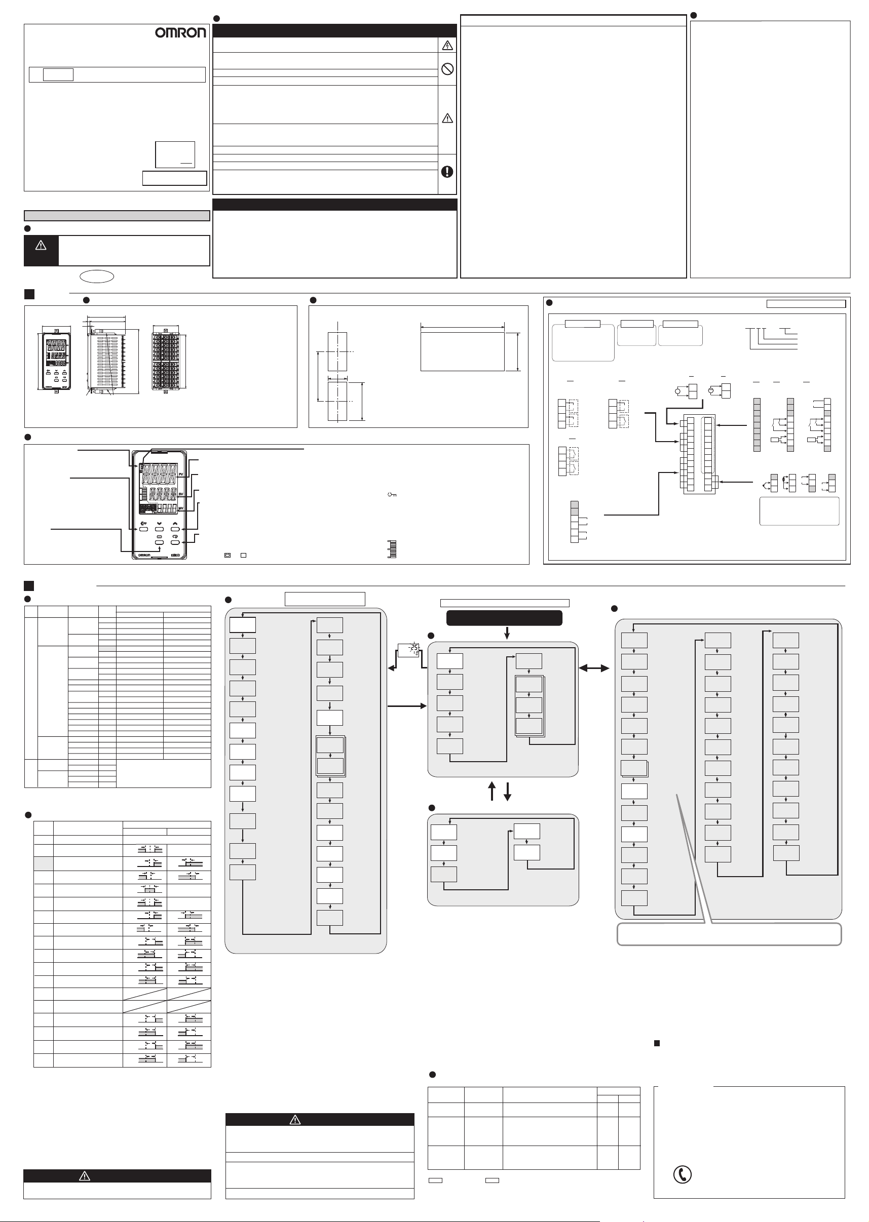
前面板的元件名称
·°C / °F:温度单位
当显示内容为温度时显示温度单位。
根据温度单位的设定值显示C或F。
·移位键(PF键)
PF设置参数默认设定为使数位移
位。此键为功能键。当按下此键,
为PF设置参数设定的功能将生效。
·菜单键
使用该键切换菜单。
·第一显示
过程值或设定数据类型
·第二显示
设定值、设定数据读出值或更改的输入值
·第三显示(默认设定下无任何显示。)
MV、剩余保温时间和多SP。
·向上和向下键
每按一次U键,第二显示上的值将增大或显
示下一个值。
每按一次D键,第二显示上的值将减小或返
回上一个值。
·模式键
按此键改变显示内容。
按该按钮1秒以上反方向显示内容。
·同时按住 键和M键
至少3秒以切换至保护菜单。
操作菜单
输入类型
输入类型 输入
铂电阻
温度计
热电偶
温度输入
红外温度
传感器ES1B
60~120°C
115~165°C
140~260°C
电流输入
类型
电压输入
模拟量输入
∗默认值是“5”。
∗当输入类型不是铂电阻而错误的将铂电阻接入时,将会显示s.err。为了清除s.err
显示,需要正确接线并重新上电。
Pt100
JPt100
K
J
T
E
L
U
N
R
S
B
C/W
PL II
10~70°C
4~20mA
0~20mA
1~5V
0~5V
0~10V
设定
0
1
2
3
4
5
6
7
8
9
10
11
12
13
14
15
16
17
18
19
20
21
22
23
24
25
26
27
28
29
设定范围
°C °F
-200~850
-199.9~500.0
0.0~100.0
-199.9~500.0
0.0~100.0
-200~1300
-20.0~500.0
-100~850
-20.0~400.0
-200~400
-199.9~400.0
-200~600
-100~850
-200~400
-199.9~400.0
-200~1300
0~1700
0~1700
0~1800
0~2300
0~1300
0~90
0~120
0~165
0~260
对比例缩放采用下列范围:-1999~9999、
-199.9~999.9、-19.99~99.99、-1.999~
9.999
-300~1500
-199.9~900.0
0.0~210.0
-199.9~900.0
0.0~210.0
-300~2300
0.0~900.0
-100~1500
0.0~
750.0
-300~700
-199.9~700.0
-300~1100
-100~1500
-300~700
-199.9~700.0
-300~2300
0~3000
0~3000
0~3200
0~3200
0~2300
0~190
0~240
0~320
0~500
报警(报警是来自辅助输出的输出。)
设定
0
∗1
1
2
3
∗1
4
5
∗1
6
7
8
9
10
11
12
13
14
15
16
17
∗1: 要使参数1、4、5提供不同的报警类型,可对其设定上限与下限。下限和上限分
别用字母 L和H指示。
• 默认的报警类型为“2”
报警类型
无报警功能
偏差上/下限
偏差上限
偏差下限
偏差上/下范围
偏差上/下限待机序列ON
偏差上限待机序列ON
偏差下限待机序列ON
绝对值上限
绝对值下限
绝对值上限待机序列ON
绝对值下限待机序列ON
LBA(仅对报警1)
PV变化率报警
SP绝对值上限
SP绝对值下限
MV绝对值上限
MV绝对值下限
正报警值(X)
ON
OFF
ON
OFF
ON
OFF
ON
OFF
ON
OFF
ON
OFF
ON
OFF
ON
OFF
0
ON
OFF
0
ON
OFF
0
ON
OFF
0
ON
OFF
0
ON
OFF
0
ON
OFF
0
ON
OFF
0
报警输出功能
无输出
LH
SP
X
SP
X
SP
LH
SP
LH
SP
X
SP
X
SP
X
X
X
X
X
X
X
X
负报警值(X)
根据L、H值
的不同而不同
X
ON
OFF
SP
ON
OFF
SP
根据L、H值
的不同而不同
根据L、H值
的不同而不同
X
ON
OFF
SP
ON
OFF
SP
X
ON
OFF
X
ON
OFF
X
ON
OFF
X
ON
OFF
X
ON
OFF
X
ON
OFF
X
ON
OFF
X
ON
OFF
X
X
0
0
0
0
0
0
0
0
符合EN/IEC标准
这是一种A类产品。
因其在住宅区中会导致无线电干扰,所以要求用户采取适当的措施减少干扰。
初始设定菜单
in-t
输入类型∗2
5
M
比例缩放上限(仅限设
in-h
定模拟量输入时)
100
M
比例缩放下限(仅限设
in-l
定模拟量输入时)
0
M
小数点(仅限设定模
dp
拟量输入时)
0
M
d-u
温度单位
c
M
sl-h
SP上限
1300
M
sl-l
SP下限
-200
M
PID·ON/OFF
cntl
使用ON/OFF控制时=onof
使用2路PID控制时=pid
pid
M
标准或加热/冷却
s-hc
标准控制时=stnd
加热冷却控制时= h-c
stnd
M
自适应控制
adpt
禁用=off
固定=fix
off
通知=info
M
自动更新=auto
模型创建
m-pv
PV振幅
0.0
M
模型创建
m-mv
MV振幅
0.0
M
初始设定菜单可以使用户指定喜欢的工作条件(输入类型、报警类
型、控制方法等等)。
*2: 关于输入类型和报警类型的详细情况,请参考旁边的表格。
*3: 当转至初始设定菜单时运行停止。
(控制和辅助输出都停止)
*4: 对于某些型号以及其它设定项的某些设定,不显示灰色设定项。
典型示例:参数在以下条件下不显示。
・AT执行/取消:如果PID ON/OFF设定为ON/OFF,不会显示。
・报警1类型:默认设定用于未配备HB/HS报警的控制器。对于配备了HB/HS报警的控
制器,辅助输出1分配参数(高级功能设定菜单)被设为加热器报警。如果设定报
警1,报警1类型参数将会显示。
有关设定方法,请参阅《E5□D数字式控制器用户手册》(Cat. No. H224)。
由于UL认证要求,请使用带有出厂接线(内部接线)的E54-CT1L或E54-CT3L电流互
感器。
使用经UL认证的UL类别XOBA或XOBA7电流互感器进行现场接线(外部接线),而非
出厂接线(内部接线)。
在使用本产品时,请务必外接说明书上推荐的保险丝。
关于模拟输入
·输入电压或电流时,请按照本产品的输入类别设定输入类型。
·请勿将本产品用来测定“测量范畴为II、III、IV”的回路。
·请勿将本产品用来测定“印加电压超过30Vrms或60VDC”的对象。
如果产品未按本公司指定的方法使用,那么产品具备的保护功能很可能损坏。
单个安装(mm) 并排安装(mm)
并排安装无法确保防水性
能。当有防水要求时,请在
前面板的后侧安装防水密封
圈。
+ 0.6
45
0
120以上
动作指示
·SUB1:辅助输出1指示
·SUB2:辅助输出2指示
·OUT1:控制输出1指示
·OUT2:控制输出2指示
自整定时点亮。
·TUNE:
·A:
自适应控制时闪烁或点亮。
运行停止。
(控制和辅助输出都停止。)
m-on
M
m-of
M
cp
20
M
c-cp
20
°C= c
°F= f
M
orev
or-r
M
alt1
M
alh1
0.2
M
ev-1
msp0
M
ev-2
stop
M
p-on
cont
M
bar
mv
M
barh
100.0
M
barl
0.0
M
amov
M
·将主单元插入面板(1~8mm厚)的安装孔中。把安装支架(提
供)插入后壳顶部和底部的固定槽中。
·拧紧适配器顶部和底部的两颗安装螺丝使其保持平衡,最终使其扭
0
+ 0.8
矩保持在0.29至0.39N·m之间。
92
·当安装多台机器时,请确保环境温度不超过规定限值。
·STOP:控制停止指示
在运行中“运行/停止”停止时点亮。
在控制停止期间,除控制输出之外的功能均有效。
·CMW:通信写入允许/禁止指示
当通信写入允许时点亮,禁止时熄灭。
· :保护指示
当设定变更保护为ON(禁用向上、向下键时)
时点亮。
·MANU:手动输出指示
当自动/手动模式设为手动模式时点亮。
·条形显示:(默认值为加热器电流。)
按10级显示MV或加热器电流。
∗3
模型创建
ON时间
0
模型创建
OFF时间
0
控制周期(加热)
(单位:秒)
∗电压输出
(用于驱动SSR):2
控制周期(冷却)
(单位:秒)
∗电压输出
(用于驱动SSR):2
正向/反向运行
反向运行(加热)中
= or-r
正向运行(冷却)中
= or-d
报警1~4
类型
2
报警
1~4
事件输入分配1
事件输入分配2
启动运行
条形显示数据
条形显示比例缩放
上限
条形显示比例缩放
下限
转至高级功能设
定菜单
0
滞后
∗2
按住O
至少3秒
(第一显示闪烁,然后
控制停止。)
按住O
至少1秒
符合安全标准
连接(端子适用性因机器型号而异。)
(48 x 单元数量 - 2.5)
+ 1.0
0
+ 0.8
通电之前检查接线。
控制输出1 控制输出2
继电器输出
250 VAC,5 A
0
92
(阻性负载)
电压输出 (用于驱动SSR)
12 VDC,40 mA
21 mA(如有两个控制输出)
控制输出1、2
QQ
两个电压输出
(用于驱动SSR)
3
OUT1
+
Q
-
4
OUT2
5
+
Q
-
6
RR
两个继电器输出
3
OUT1
R
4
5
OUT2
R
6
辅助输出
辅助输出1~2
7
8
9
辅助输出2
10
11
辅助输出1
12
QR
电压输出(
和继电器输出
3
4
5
6
继电器输出
250 VAC,5 A
(阻性负载)
用于驱动SSR)
OUT1
+
Q
-
OUT2
R
调整菜单
通电
操作菜单
过程值/设定值
25
连接的传感器与输入
类型不同时,显示
0
s.err。
M
多SP
m-sp
设定值选择
0
M
sp-m
SP斜坡期间的设定值
0
M
加热器电流1
ct1
值监控
0.0
(单位:A)
M
漏电流1
lcr1
值监控
0.0
(单位:A)
M
操作时应正常使用操作菜单。
按住O和M键至少1秒
保护菜单
操作/调整保护
限制在操作菜单、调整菜
oapt
单和手动控制菜单中显示
0
和修改菜单项。
M
初始设定/通信保护
限制切换至初始设定菜单、
icpt
通信设定菜单和高级功能
1
设定菜单。
M
设定变更保护
wtpt
限制通过操作前面板按键
来改变设定。
off
M
限制可以显示或改变的设定类型以及通过按键操作进行的更改。
按住M键反向循环显示参数。
错误显示(故障诊断)
当发生一个错误时,第一显示将显示错误代码。参考下表,根据错误代码采取适当的措施。
第一显示
s.err(S. Err)
e333(E333)
e111(E111)
如果输入值超过显示范围(-1999~9999),即使仍处于控制范围内,低于-1999的将显示
[[[[ ,高于9999的显示 ]]]] 。在这些条件下,控制输出和报警将正常运行。
关于可控制的范围,请参阅《E5□D数字式控制器用户手册》(Cat. No. H224)。
∗5:错误显示只针对“过程值/设定值”,而不针对其它状态。
含义
输入错误
∗5
A/D转换错误
∗5
内存错误
检查输入类型参数的设置,检查输入接线并检查温
度传感器是否存在破损或短接。
确认输入异常后,请重新接通电源。如果显示不变,
则须修理控制器。如果显示恢复正常,则故障原因
可能是控制系统受到外部干扰。请检查外部干扰。
关掉电源再打开。如果显示不变,则须修理控制器。
如果显示恢复正常,则可能是控制系统受到外部干
扰。请检查外部干扰。
RUN/STOP
r-s
当控制启动=run时
当控制停止=stop时
run
M
al-1
报警值1~4
0
M
报警值上限
al1h
1~4
0
M
报警值下限
al1l
1 ~4
0
M
按住O和M键至少3秒
PF键保护
pfpt
限制PF键操作。
off
M
M
pmsk
允许参数屏蔽
on
M
操作
按O
(不超过
1秒)
cmwt
lcr1
sp-0
a-ud
w-ht
w-il
只有“ins时:温度输入偏移”参数中的设定值应用于整个温度输入范围。如果输入偏移值设定
为1.2°C,则过程值为200°C时,经过输入偏移后按照201.2°C处理。而如果输入偏移值设定为
-1.2°C,则经过输入偏移后过程值按照198.8°C处理。
出错状态
报警
控制输出
同上述上限
OFF
报警工作
OFF
OFF
OFF
OFF
请勿在灰色端子上连接任何器件。
辅助输出1、2
继电器输出
250 VAC,3 A
(阻性负载)
输入电源
A D
1
~ ~
2
1
2
3
4
5
6
7
8
9
10
11
12
*1.
为符合EMC标准,连接传感器的电缆不得超过30米。如果电缆长度超过30米,则不符合EMC标准。
*2.
对事件输入使用无电压输入。无触点输入的极性由“(-)”表示。
AT执行/取消
at
100%AT执行at-2
40%AT执行at-1
off
M
通信写入
off
M
加热器电流1值监控
ct1
(单位:A)
0.0
M
加热器断线检测1
hb1
(单位:A)
0.0
M
漏电流1值监控
(单位:A)
0.0
M
HS报警1
hs1
(单位:A)
50.0
M
SP 0 ~ 7
0
M
ins
PV输入偏移量
0.0
M
自动过滤器调整
fa
off
M
输入数字过滤器
inf
0.0
M
PID更新
(自适应控制)
off
M
水冷输出调整
off
M
水冷比例带增加阈值
1.4
M
其它功能
有关高级功能设定菜单、手动控制菜单以及其它功能的信息,请参考《E5□D数字式
控制器用户手册》(Cat. No. H224)。
有关通信的详细信息,请参阅《E5□D数字式控制器通信手册》(Cat. No. H225)。
E5ED-@@@@DM-82@
选项
820 828821
2个事件输入
和1个CT
13
14
15
(−)
16
17
EV1
18
EV2
19
CT1
20
21
传感器温度和模拟量输入
TC
22
−
23
24
+
E5ED默认设定为一K型热电偶(输入类
型5)。如果使用不同的传感器,则会发
生输入错误(s.err)。检查输入类型参
数的设置。
13
14
15
16
17
18
19
20
21
22
23
24
(无极性)
w-dl
M
M
233
M
M
c-p
300.0
M
c-i
233
M
c-d
M
sp-p
M
sp-i
233
M
sp-d
M
sp-n
M
1
2
水冷比例带
降低阈值
0.6
p
比例带
8.0
积分时间
i
(单位:秒)
微分时间
d
(单位:秒)
40
比例带
(冷却)
积分时间
(冷却)
(单位:秒)
微分时间
(冷却)
(单位:秒)
40
SP响应比例带
8.0
SP响应积分时间
(单位:秒)
SP响应微分时间
(单位:秒)
40
SP响应系数编号
0
调整菜单用于在控制时输入设定值和偏移值。
13
14
15
16
17
18
19
20
21
A
B
B
d-p
M
d-i
233
M
d-d
M
c-db
M
of-r
50.0
M
hys
M
chys
M
sprt
off
M
ol-h
100.0
M
ol-l
M
plcm
M
Pt I
22
23
24
8.0
40
0.0
1.0
1.0
0.0
■联系方式
制造商
●
欧姆龙(上海)有限公司
地址:中国(上海)自由贸易试验区金吉路789号
电话: (86)21-50509988
技术咨询
●
欧姆龙自动化(中国)有限公司
地址
:中国上海市浦东新区银城中路200号中银大厦2211室
电话: (86)21-5307-2222
技术咨询热线
400-820-4535
网址:http://www.fa.omron.com.cn
选项
输入电源
辅助输出
控制输出1、2
通信、2个事件输入
和1个CT
RS-485
EV2
CT1
+
22
mA
23
−
24
干扰比例带
干扰积分时间
(单位:秒)
干扰微分时间
(单位:秒)
死区
手动复位值
清除P或PD控制
期间的偏移量
滞后(加热)
滞后(冷却)
SP斜坡设定值
MV上限
MV下限
通信监控
0
B(+)
13
14
A(−)
15
(−)
16
17
EV1
18
19
20
21
V
22
−
23
V
24
+
Page 2
Warning Symbols
E5ED-82
Digital Controller
INSTRUCTION MANUAL
EN
Thank you for purchasing the
This manual describes the functions, performance, and
application methods needed for optimum use of the product.
Please observe the following items when using the product.
• This product is designed for use by qualified personnel with
a knowledge of electrical systems.
• Before using the product, thoroughly read and understand
this manual to ensure correct use.
• Keep this manual in a safe location so that it is available for
reference whenever required.
OMRON Corporation
©All Rights Reserved
Refer to the
E5D Digital Controllers User’s Manual (Cat. No. H224)
application procedures.
Key to Warning Symbols
Indicates a potentially hazardous situation which, if
not avoided, is likely to result in minor or moderate
CAUTION
injury or property damage. Read this manual
carefully before using the product.
Wiring
Dimensions (mm)
48
96
* You can remove only the interior body of the Digital Controller from the case with the Draw-out Jig to perform maintenance without
removing the terminal leads. Refer to the
* Do not remove the terminal block. Doing so may result in failure or malfunction.
OMRON E5ED Digital Controller.
for detailed
Safety Precautions
3102754-8B (Side-B)
Dimensions Installation
(64)
4
60
1
E5D Digital Controllers User’s Manual (Cat. No. H224)
Crimp Terminal Sizes: M3
44
110
Minor injury due to electric shock may occasionally occur.
Do not touch the terminals while power is being supplied.
Electric shock, fire, or malfunction may occasionally occur. Do not allow metal objects, conductors, debris
(such as cuttings) from installation work, moisture, or other foreign matter to enter the Digital Controller.
Do not use the product where subject to flammable or explosive gas. Otherwise, minor injury
explosion may occasionally occur.
from
Never disassemble, modify, or repair the product or touch any of the internal parts. Minor
electric shock, fire, or malfunction may occasionally occur.
CAUTION - Risk of Fire and Electric Shock
a)
This is the product UL Listed as Open Type Process Control Equipment. It must be mounted in an enclosure
that does not allow fire to escape externally.
b) More than one disconnect switch may be required to de-energize the equipment before servicing.
c) Signal inputs are SELV, limited energy.
d)
Caution: To reduce the risk of fire or electric shock, do not interconnect the outputs of different Class 2 circuits.
If the output relays are used past their life expectancy, contact fusing or burning may occasionally
occur. Always consider the application conditions and use the output relays within their rated load
and electrical life expectancy. The life expectancy of output relays varies considerably with the
output load and switching conditions.
The maximum terminal temperature is 75°C. Use wires with a heat resistance of 75°C min to wire the terminals.
Loose screws may occasionally result in fire.
Tighten the terminal screws to the specified torque of 0.43 to 0.58 N•m.
Set the parameters of the product so that they are suitable for the system being controlled. If they
are not suitable, unexpected operation may occasionally result in property damage or accidents.
A malfunction in the Digital Controller may occasionally make control operations impossible
or prevent alarm outputs, resulting in property damage. To maintain safety in the event of
malfunction of the Digital Controller, take appropriate safety measures, such as installing a
monitoring device on a separate line.
Omron Companies shall not be responsible for conformity with any standards, codes or regulations which
apply to the combination of the Product in the Buyer’s application or use of the Product.
At Buyer’s request, Omron will provide applicable third party certification documents identifying ratings and
limitations of use which apply to the Product. This information by itself is not sufficient for a complete
determination of the suitability of the Product in combination with the end product, machine, system, or other
application or use. Buyer shall be solely responsible for determining appropriateness of the particular Product
with respect to Buyer’s application, product or system. Buyer shall take application responsibility in all cases.
NEVER USE THE PRODUCT FOR AN APPLICATION INVOLVING SERIOUS RISK TO LIFE OR
PROPERTY WITHOUT ENSURING THAT THE SYSTEM AS A WHOLE HAS BEEN DESIGNED TO
ADDRESS THE RISKS, AND THAT THE OMRON PRODUCT(S) IS PROPERLY RATED AND INSTALLED
FOR THE INTENDED USE WITHIN THE OVERALL EQUIPMENT OR SYSTEM.
In the pack:
• Main unit
• Instruction manual
• Watertight packing (Y92S-P9):
• Two adapters (Y92F-51):
91
Sold Separately
• Terminal cover (E53-COV24)
• Draw-out Jig (Y92F-59)
• Front-panel Setup Tool port cover (Y92S-P7)
for instructions.
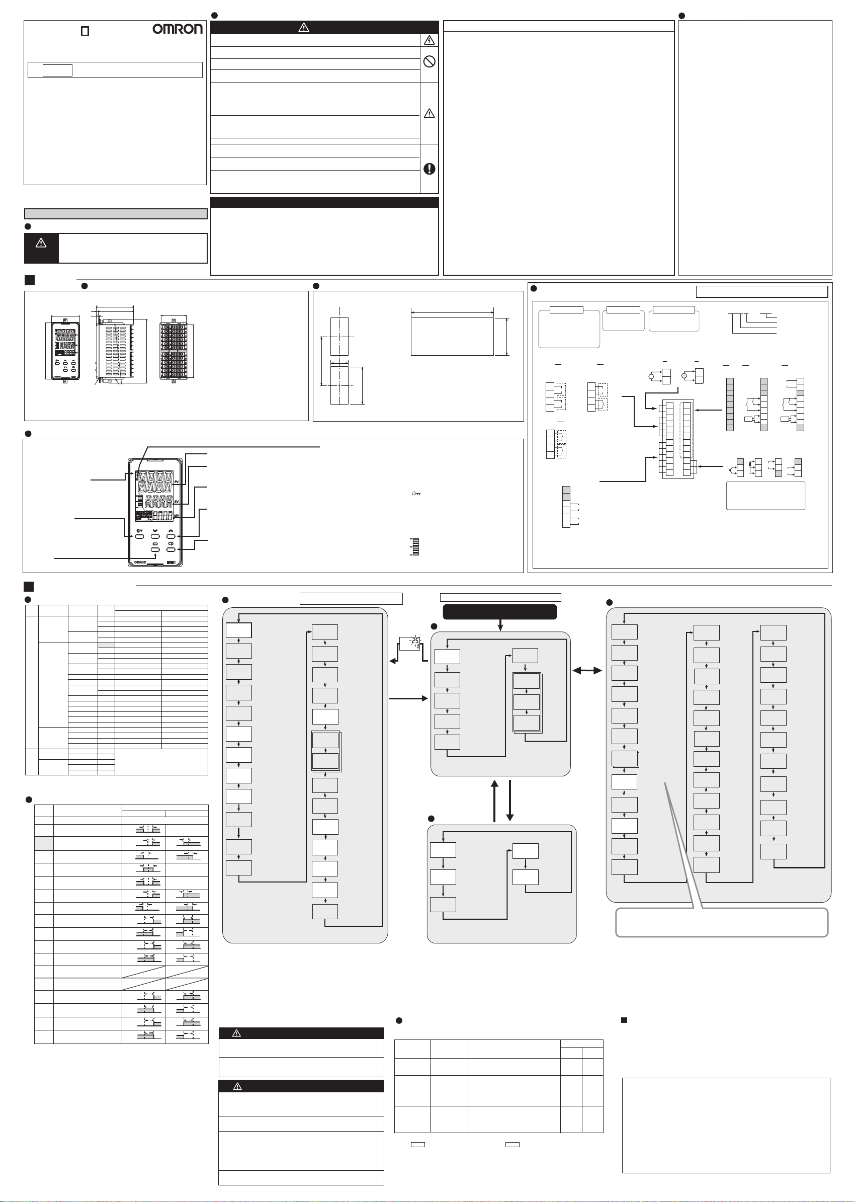
Names of Parts on Front Panel
• No.1 display
Process value or set data type
• No.2 display
Set point, set data read-out value or changed
• °C / °F : temperature unit
The temperature unit is displayed when
the displayed value is a temperature.
Either C or F is displayed according to the
set value of the temperature unit.
• Shift key (PF key)
The default PF Setting parameter is for
shifting the digit. This is a function key.
When it is pressed, the function set for the
PF Setting parameter will operate.
• Level key
Use this key to change levels:
input value
• No. 3 display
(Nothing is displayed at the default settings.)
MV, Soak Time Remain, and Multi-SP.
• Up and Down keys
Each press of U key increments or advances
the values displayed on the No.2 display.
Each press of D key decrements or returns the
values displayed on the No.2 display.
• Mode key
Press this key to change the contents of the display.
Press this button for 1 s or longer for reverse scroll.
• Press the O key and the M key
together for at least 3 seconds to switch to protect level.
CAUTION
Suitability for Use
Individual mounting (mm
n
i
+ 0.6
m
45
0
0
2
1
Operation indicators
• SUB1: Auxiliary output 1 indicator
• SUB2: Auxiliary output 2 indicator
• OUT1: Control output 1 indicator
• OUT2: Control output 2 indicator
• TUNE:
Lit during auto-tuning.
• A:
Flashing or lit during adaptive control.
Be sure to observe the following precautions to prevent operation failure, malfunction, or adverse affects on theperformance
and functions of the product. Not doing so may occasionally result in unexpected events. Use theproduct within specifications.
(1) The product is designed for indoor use only. Do not use the product outdoors. Do not use or store the product in any of
the following locations.
• Places directly subject to heat radiated from heating equipment.
• Places subject to splashing liquid or oil atmosphere.
• Places subject to direct sunlight.
• Places subject to intense temperature change.
• Places subject to icing and condensation.
• Places subject to vibration and large shocks.
• Places subject to dust or corrosive gas (in particular, sulfide gas and ammonia gas).
(2)
Use and store the Digital Controller within the rated ambient temperature and humidity. Provide forced-cooling if required.
(3) To allow heat to escape, do not block the area around the product. Do not block the ventilation holes on the product.
(4) Be sure to wire properly with correct signal name and polarity of terminals.
(5) Use the specified size of crimped terminals (M3, width 5.8 mm or less) for wiring. To connect bare wires to the terminal
block, use copper braided or solid wires with a gage of AWG24 to AWG18 (equal to a crosssectional area of 0.205 to
0.823 mm
be inserted into a single terminal.
(6) Do not wire the terminals which are not used.
(7) Allow as much space as possible between the controller and devices that generate a powerful high-frequency or surge.
Separate the high-voltage or large-current power lines from other lines, and avoid parallel or common wiring with the
power lines when you are wiring to the terminals.
(8) Use the Digital Controller within the rated load and power supply.
(9) Make sure that the rated voltage is attained within two seconds of turning ON the power using a switch or relay
contact. If the voltage is applied gradually, the power may not be reset or output malfunctions may occur.
(10) Make sure that the Digital Controller has 30 minutes or more to warm up after turning ON the power before starting
actual control operations to ensure the correct temperature display.
(11)
When using adaptive control, turn ON power for the load at the same time as or before supplying power to the Digital Controller.
(12) During tuning, ensure that the power for the load (e.g., heater) is ON. Otherwise, the correct tuning result cannot be
calculated and optimal control will not be possible. Tuning is used in the following functions:
AT, adaptive control, automatic filter adjustment, and water-cooling output adjustment.
(13) A switch or circuit breaker should be provided close to this unit. The switch or circuit breaker should be within easy
reach of the operator, and must be marked as a disconnecting means for this unit.
(14) Wipe off any dirt from the Digital Controller with a soft dry cloth. Never use thinners, benzine, alcohol, or any cleaners
that contain these or other organic solvents. Deformation or discoloration may occur.
(15)
Design system (control panel, etc) considering the 2 second of delay that the controller’s output to be set after power ON.
(16)
The output will turn OFF when you move to the Initial Setting Level. Take this into consideration when performing control.
(17) The number of non-volatile memory write operations is limited. Therefore, use RAM write mode when frequently
overwriting data during communications or other operations.
(18) When disassembling the Digital Controller for disposal, use suitable tools.
(19)
Do not exceed the communications distance that is given in the specifications and use the specified communications cable.
Refer to the E5D Digital Controllers User’s Manual (Cat. No. H224) for the communications distance and cable specifications.
(20) Always turn OFF the power supply before pulling out the interior of the product, and never touch nor apply shock to the
terminals or electronic components.
When inserting the interior of the product, do not allow the electronic components to touch the case.
When you insert the interior body into the case, confirm that the hooks on the top and bottom are securely engaged with the case.
If the terminals are corroded, replace the rear case as well.
(21) Do not use the Temperature Controller if the front sheet is peeling.
)
Side-by-side mounting (mm)
(48 x number of units–2.5)
Waterproofing is
impossible with
side-by-side installation.
When waterproofing is
required, fit watertight
packing on the
backside of front panel.
• Insert the main unit through the mounting hole in the panel
(1 to 8 mm thickness). Insert the mounting brackets (supplied)
8.0
0
into the fixing slots located on the top and bottom of the rear
+
case.
29
• Tighten the two mounting screws on the top and bottom of
the adapter to keep them balanced, and finally tighten them
to a torque of between 0.29 and 0.39 N·m.
• When more than one machine is installed, make sure that the
ambient temperature does not exceed the specified limit.
• STOP: Control stop indicator
Lit when “Run/Stop” is stopped during operation.
During control stop, functions other than control output
are valid.
•
CMW: Communications writing enable/ disable indicator
Lit when communications writing is “enabled” and is
out when it is “disabled”.
• : Protection indicator
Lit when Setting Change Protect is ON (disables the
Up and Down Keys).
• MANU: Manual output indicator
Lit when the Auto/Manual Mode is set to Manual
Mode.
• Bar Display:
(The default value is heater current.)
Displays the MV or heater current in 10 steps.
Precautions for Safe Use
2
). (The stripping length is 6 to 8 mm.). Up to two wires of same size and type, or two crimped terminals can
Connections
(The applicability of the electric terminals varies with the type of machine.)
+ 1.0
0
8
.
0
0
+
29
Control output 1
Relay output
250 VAC, 5A (resistive load)
Voltage output (for driving SSR)
12 VDC, 40 mA
21 mA if there are
two control outputs
Control Outputs 1, 2
QQ
Two voltage outputs
(for driving SSRs)
3
OUT1
+
Q
-
4
OUT2
5
+
Q
-
6
RR
Two relay outputs
3
OUT1
R
4
5
OUT2
R
6
Auxiliary Outputs
Auxiliary outputs 1 to 2
7
8
9
Auxiliary output 2
10
11
Auxiliary output 1
12
*1. When complying with EMC standards, the line connecting the sensor must be 30 m or less.
If the cable length exceeds 30 m, compliance with EMC standards will not be possible.
*2. Use non-voltage inputs for the event inputs. The polarity for a non-contact input is indicated by “(-).”
Control output 2
Relay output
250 VAC, 5A
(resistive load)
QR
Voltage output
(for driving SSRs)
and relay output
3
OUT1
+
Q
-
4
5
OUT2
R
6
Auxiliary output 1, 2
Input Power Supply
100 to 240 VAC 24 VAC/DC
~
Relay output
250 VAC, 3 A
(resistive load)
A D
1
2
1
2
3
4
5
6
7
8
9
10
11
12
Specifications
Power supply voltage
Operating voltage range
Power consumption
Option 820:
All other specifications:
Indication accuracy
(Ambient temperature: 23°C)
Event input
Contact input
No-contact input
Control output 1
Control output 2
Control method
Auxiliary outputs
Ambient temperature
Ambient humidity
Storage temperature
Altitude
Recommended fuse
Weight
Degree of protection
Installation environment
Memory protection
Do not connect anything to the terminals that are shaded gray.
1
~
2
(no polarity)
13
14
15
16
17
18
19
20
21
22
23
24
100 to 240 VAC, 50/60 Hz or
24 VAC, 50/60 Hz / 24VDC
85 to 110% of the rated voltage
6.6 VA max. (100 to 240 VAC)
4.1 VA max. (24 VAC)/2.3 W max. (24 VDC)
8.3 VA max. (100 to 240 VAC)
5.5 VA max. (24 VAC)/3.2 W max. (24 VDC)
Thermocouple:
(±0.3 % of indication value or ±1°C,
whichever is greater) ±1 digit max.
Platinum resistance thermometer:
(±0.2 % of indication value or ±0.8°C,
whichever is greater) ±1 digit max.
Analog input: ±0.2 % FS ±1 digit max.
Output current: approx. 7 mA per contact.
ON:1 kΩ max., OFF: 100 kΩ min.
ON: residual voltage 1.5 V max.,
OFF: leakage current 0.1 mA max.
Relay output :SPST-NO
250VAC, 5A (resistive load)
Electrical life of relay: 100,000 operations
Voltage output (for driving SSR):
12 VDC ±20%, 40 mA for one control output,
21 mA if there are two control outputs
Relay output: SPST-NO,
250 VAC, 5 A (resistive load)
Electrical life of relay: 100,000 operations
ON/OFF or 2-PID control
Relay outputs: 250 VAC, 3 A (resistive load)
Electrical life of relay: 100,000 operations
–10 to 55°C
(Avoid freezing or condensation)
25 to 85%
–25 to 65°C
(Avoid freezing or condensation)
Max. 2,000 m
T2A, 250 VAC, time-lag, low-breaking capacity
Approx. 210 g (Digital Controller only)
Front panel: IP66
Rear case: IP20, Terminal section: IP00
Overvoltage category II, pollution
degree 2 (as per IEC61010-1)
Non-volatile memory
(Number of write operations: 1,000,000)
E5ED-
@@@@DM-82@
Options
820
821
Two event inputs,
and one CT
13
14
15
16
17
18
19
20
21
Sensor Temperature/Analog Input
The E5ED is set for a K thermocouple
(input type of 5) by default. If a different
sensor is used, an input error (s.err) will
occur. Check the setting of the Input Type
parameter.
13
14
15
(−)
16
17
EV1
18
EV2
19
CT1
20
21
TC
Pt I
A
22
22
B
−
23
23
B
24
24
+
Options
Input Power Supply
Auxiliary Outputs
Control Outputs 1, 2
828
Communications, two
event inputs, and one CT
RS-485
EV2
CT1
+
22
mA
23
−
24
B(+)
13
14
A(−)
15
(−)
16
17
EV1
18
19
20
21
V
22
−
23
V
24
+
Operation Menu
Input Type
Pt100
JPt100
K
J
T
E
L
U
N
R
S
B
C/W
PL II
10 to 70°C
60 to 120°C
115 to 165°C
140 to 260°C
4 to 20mA
0 to 20mA
1 to 5V
0 to 5V
0 to 10V
Setting
10
11
12
13
14
15
16
17
18
19
20
21
22
23
24
25
26
27
28
29
0
1
2
3
4
5
6
7
8
9
Input type Input
Platinum
resistance
thermometer
Thermocouple
Temperature inputs
Infrared
Thermosensor
ES1B
Current input
Voltage input
Analog
input type
• The default is“5”.
•
s.err will be displayed when a platinum resistance thermometer is mistakenly connected while
input type is not set for it. To clear the s.err display, correct the wiring and cycle the power supply.
Alarms (Alarms are output from auxiliary outputs.)
Setting
0
*1
1
2
3
*1
4
5
*1
6
7
8
9
10
11
12
13
14
15
16
17
*1: Upper and lower limits can be set for parameters 1, 4 and 5 to provide for different types
of alarm. These are indicated by the letter "L" and "H".
• The default alarm type is "2"
Alarm type
No alarm function
Deviation upper/lower limit
Deviation upper limit
Deviation lower limit
Deviation upper/lower range
Deviation upper/lower limit
standby sequence ON
Deviation upper limit
standby sequence ON
Deviation lower limit
standby sequence ON
Absolute value upper limit
Absolute value lower limit
Absolute value upper limit
standby sequence ON
Absolute value lower limit
standby sequence ON
LBA (only for alarm 1)
PV Change Rate Alarm
SP absolute value upper limit
SP absolute value lower limit
MV absolute value upper limit
MV absolute value lower limit
Setting range
°C
-200 to 850
-199.9 to 500.0
0.0 to 100.0
-199.9 to 500.0
0.0 to 100.0
-200 to 1300
-20.0 to 500.0
-100 to 850
-20.0 to 400.0
-200 to 400
-199.9 to 400.0
-200 to 600
-100 to 850
-200 to 400
-199.9 to 400.0
-200 to 1300
0 to 1700
0 to 1700
0 to 1800
0 to 2300
0 to 1300
0 to 90
0 to 120
0 to 165
0 to 260
Use the following ranges for scaling: -1999
to 9999, -199.9 to 999.9, -19.99 to 99.99,
-1.999 to 9.999
Alarm output function
Positive alarm value (X)
LH
ON
OFF
SP
X
ON
OFF
SP
X
ON
OFF
SP
LH
ON
OFF
SP
LH
ON
OFF
SP
X
ON
OFF
SP
X
ON
OFF
SP
X
ON
OFF
0
X
ON
OFF
0
X
ON
OFF
0
X
ON
OFF
0
X
ON
OFF
0
X
ON
OFF
0
X
ON
OFF
0
X
ON
OFF
0
-300 to 1500
-199.9 to 900.0
0.0 to 210.0
-199.9 to 900.0
0.0 to 210.0
-300 to 2300
0.0 to 900.0
-100 to 1500
0.0 to 750.0
-300 to 700
-199.9 to 700.0
-300 to 1100
-100 to 1500
-300 to 700
-199.9 to 700.0
-300 to 2300
0 to 3000
0 to 3000
0 to 3200
0 to 3200
0 to 2300
0 to 190
0 to 240
0 to 320
0 to 500
Negative alarm value (X)
Output off
Vary with
"L", "H" values
ON
OFF
ON
OFF
Vary with
"L", "H" values
Vary with
"L", "H" values
ON
OFF
ON
OFF
ON
OFF
ON
OFF
ON
OFF
ON
OFF
ON
OFF
ON
OFF
ON
OFF
ON
OFF
°F
X
SP
X
SP
X
SP
X
SP
X
0
X
0
X
0
X
0
X
0
X
0
X
0
X
0
Initial Setting Level
in-t
Input Type *2
5
M
Scaling Upper Limit
in-h
(only when setting
analog input)
100
M
Scaling Lower Limit
in-l
(only when setting
analog input)
0
M
Decimal Point
dp
(only when setting
analog input)
0
M
Temperature
d-u
Unit
c
M
sl-h
SP Upper Limit
1300
M
sl-l
SP Lower Limit
-200
M
PID•ON/OFF
cntl
In ON/OFF control =
pid
In 2-PID control = pid
M
Standard or Heating/Cooling
s-hc
Standard control =
h-c
Heating and cooling control =
M
Adaptive Control
adpt
Disabled =
Fixed =
off
Notification =
M
Automatic update =
Model Creation
m-pv
PV Amplitude
0.0
M
Model Creation
m-mv
MV Amplitude
0.0
Initial setting level enables users to specify their preferred operating
conditions (input type, alarm type, control method, etc.)
*2: Refer to the adjoining tables for details of input types and alarm types.
Operation is stopped when moved to the initial setting level. (Both control and auxiliary outputs are stopped.)
*3:
*4:
The grayed-out setting items are not displayed for some models and some settings of other setting items.
Typical example: The parameters are not displayed under the following conditions.
• AT Execute/Cancel: Not displayed if PID ON/OFF is set to ON/OFF.
Alarm 1 Type: The default setting is for Controllers that are not equipped with HB/HS alarms.
•
For a Controller equipped with HB/HS alarms, the Auxiliary Output 1 Assignment parameter (Advanced Function
Setting Level) is set to a heater alarm. If you set alarm 1, the Alarm 1 Type parameter will be displayed.
Refer to the
E5D Digital Controllers User’s Manual (Cat. No. H224)
Conformance to EN/IEC Standards
This is a class A product.
In residential areas it may cause radio interference, in which case the user
may be required to take adequate measures to reduce interference.
A 급 기기 (업무용 방송통신기자재)
이 기기는 업무용(A 급) 전자파적합기기로서 판매자또는 사용자는 이 점을
주의하시기 바라며, 가정외의지역에서 사용하는 것을 목적으로 합니다.
Operation stopped.
(Both control and auxiliary outputs are stopped.)
Model Creation
m-on
ON Time
0
M
Model Creation
m-of
OFF Time
0
M
Control Period (Heating)
(Unit: Seconds)
cp
*Voltage output
20
(for driving SSR): 2
M
Control Period (Cooling)
(Unit: Seconds)
c-cp
*Voltage output
20
(for driving SSR): 2
M
°C= c
°F= f
onof
stnd
h-c
off
fix
info
auto
orev
or-r
M
alt1
M
alh1
M
ev-1
msp0
M
ev-2
stop
M
p-on
cont
M
bar
M
barh
100.0
M
barl
0.0
M
amov
M
2
0.2
mv
0
Direct/Reverse Operation
In Reverse operation
(Heating) =
In Direct operation
(Cooling) =
Alarm 1 to 4 Type
Alarm 1 to 4
Hysteresis
Event Input
Assignment 1
Event Input
Assignment 2
Startup Operation
Bar Display Data
Bar Display Scaling
Upper Limit
Bar Display Scaling
Lower Limit
Move to Advanced
Function Setting
Level
or-r
or-d
*2
for the setting method.
Conformance to Safety Standard
Due to UL Listing requirements, use the E54-CT1L or E54-CT3L current
transformer with the factory wiring (internal wiring).
Use a UL category XOBA or XOBA7 current transformer that is UL Listed
for field wiring (external wiring) and not the factory wiring (internal wiring).
Always externally connect the recommended fuse that is specified in the
Instruction Manual before you use the Digital Controller.
Analog Input
• If you input an analog voltage or current, set the Input Type parameter to
the correct input type.
• Do not use the Digital Controller to measure a circuit with Measurement
Category II, III, or IV.
• Do not use the Digital Controller to measure an energized circuit to which
a voltage that exceeds 30 Vrms or 60 VDC is applied.
The protection provided by the Digital Controller may be impaired if the Digital
Controller is used in a manner that is not specified by the manufacturer.
*3
Hold O down
for at least
3 seconds
(No.1 display flashes,
then the control stops.)
Hold O down
for at least
1 second
Error Display (troubleshooting)
When an error has occurred, the No.1 display shows the error code. Take necessary measure
according to the error code, referring the table below.
No.1 display
s.err (S. Err)
e333 (E333)
e111 (E111)
If the input value exceeds the display limit (-9999 to 9999), though it is within the control
range, [[[[ will be displayed under -1999 and ]]]] above 9999.
Under these conditions, control outputs and alarms will operate normally.
Refer to the
*5: Error shown only for "Process value / Set point". Not shown for other status.
Check the wiring before turning ON the power supply.
POWER ON
Operation Level
Process Value/Set Point
s.err
is displayed when
25
connected sensor is
0
different from input type.
M
Multi-SP
m-sp
Set Point Selection
0
M
Set Point During
sp-m
SP Ramp
0
M
Heater Current 1
ct1
Value Monitor
(Unit: A)
0.0
M
Leakage Current 1
lcr1
Value Monitor
(Unit: A)
0.0
M
M
Operation level should normally be used during operations.
Hold O and M keys
down for at least 1 second
Protect Level
Operation / Adjustment Protect
Restricts displaying and
oapt
modifying menu items in
Operation, Adjustment, and
0
Manual Control Levels.
M
Initial Setting /
Protect
Communication
icpt
Restricts movement to the
Initial Setting, Communications
1
Setting, and Advanced Function
M
Setting Levels.
Setting Change Protect
wtpt
Restricts changes to settings
by operating the front panel keys.
off
M
Restricts which settings can be displayed or changed, and restricts
change by key operation.
Press and hold the M Key to cycle through the parameters in reverse.
Meaning
Input error
A/D converter error
Memory error
Check the setting of the Input Type parameter,
check the input wiring, and check for broken or
*5
shorts in the temperature sensor.
After the check of input error, turn the power OFF
then back ON again. If the display remains the
same, the controller must be repaired. If the
*5
display is restored to normal, then a probable
cause can be external noise affecting the control
system. Check for external noise.
Turn the power OFF then back ON again. If the
display remains the same, the controller must be
repaired. If the display is restored to normal, then
a probable cause can be external noise affecting
the control system. Check for external noise.
E5D Digital Controllers User’s Manual (Cat. No. H224)
Action
RUN/STOP
When control start
r-s
=
run
When control stop
run
=
stop
M
Alarm Va
al-1
1 to 4
0
M
Alarm Value
al1h
Upper Limit
0
1 to 4
M
Alarm Value
al1l
Lower Limit
0
1 to 4
M
M
Hold O and M keys
down for at least 3 seconds
PF Key Protect
pfpt
Restricts PF
key operation.
off
M
Parameter Mask
pmsk
Enable
on
M
for the controllable ranges.
(The No.3 display
has been omitted.)
lue
Status at error
Control
output
OFF
OFF
OFF
Press O
(less than
1 second)
Alarm
Operates
as above the
upper limit.
OFF
OFF
Adjustment Level
AT Execute/Cancel
at
100%AT Execute at-2
off
40%AT Execute at-1
M
cmwt
Communications Writing
off
M
Heater Current 1
ct1
Value Monitor
0.0
(Unit: A)
M
Heater Burnout
hb1
Detection 1
0.0
(Unit: A)
M
Leakage Current 1
lcr1
Value Monitor
0.0
(Unit: A)
M
HS Alarm 1
hs1
(Unit: A)
5 0.0
M
sp-0
SP 0 to 7
0
M
PV
ins
Input Shift
0.0
M
Automatic Filter
fa
Adjustment
off
M
inf
Input Digital Filter
0.0
M
PID Update
a-ud
(Adaptive Control)
off
M
Water-cooling
w-ht
Output Adjustment
off
M
Only the value set to the ins: Temperature Input Shift parameter is applied to the entire
temperature input range. When the process value is 200°C, the process value is treated as
201.2°C after input shift if the input shift value is set to 1.2°C. The process value is treated
as 198.8°C after input shift if the input shift value is set to -1.2°C.
Other functions
Refer to the
E5D Digital Controllers User’s Manual (Cat. No. H224)
Advanced Function Setting Level, Manual Control Level, and other functions.
Refer to the E5
on communications.
OMRON EUROPE B.V. (Importer in EU)
Wegalaan 67-69, NL-2132 JD Hoofddorp The Netherlands
Phone 31-2356-81-300
FAX 31-2356-81-388
OMRON ELECTRONICS LLC
2895 Greenspoint Parkway, Suite 200 Hoffman Estates, IL 60169 U.S.A.
Phone 1-847-843-7900
FAX 1-847-843-7787
OMRON ASIA PACIFIC PTE. LTD.
No. 438A Alexandra Road # 05-05/08 (Lobby 2),
Alexandra Technopark, Singapore 119967
Phone 65-6835-3011
FAX 65-6835-2711
OMRON Corporation (Manufacturer)
Shiokoji Horikawa, Shimogyo-ku, Kyoto 600-8530 JAPAN
D Digital Controllers Communications Manual
Water-cooling
w-il
Proportional Band
Increase Threshold
1.4
M
Water-cooling
Proportional
w-dl
Band Decrease
0.6
Threshold
M
Proportional
p
Band
8.0
M
Integral Time
i
(Unit: Seconds)
233
M
Derivative Time
d
(Unit: Seconds)
40
M
Proportional
c-p
Band (Cooling)
300.0
M
Integral Time
c-i
(Cooling)
(Unit: Seconds)
233
M
Derivative Time
c-d
(Cooling)
(Unit: Seconds)
40
M
SP Response
sp-p
Proportional Band
8.0
M
SP Response
sp-i
Integral Time
(Unit: Seconds)
233
M
SP Response
sp-d
Derivative Time
(Unit: Seconds)
40
M
SP Response
sp-n
Coefficient
Number
0
M
Adjustment level is for entering set values and
shift values for control.
d-p
d-i
d-d
c-db
of-r
hys
chys
sprt
ol-h
100.0
ol-l
-100.0
plcm
for information on the
(Cat.No. H225)
Disturbance
Proportional Band
8.0
M
Disturbance
Integral Time
(Unit: Seconds)
233
M
Disturbance
Derivative Time
(Unit: Seconds)
40
M
Dead Band
0.0
M
Manual Reset Value
Clears the offset
during P or PD control.
50.0
M
Hysteresis
(Heating)
1.0
M
Hysteresis
(Cooling)
1.0
M
SP Ramp Set Value
off
M
MV Upper Limit
M
MV Lower Limit
M
Communications
Monitor
0
M
for information
 Loading...