

»
Pe r fe ct co ntr ol
»
Enh a n c e d f u n c t i o n a l i t y
»
Ea sy set ti ng up
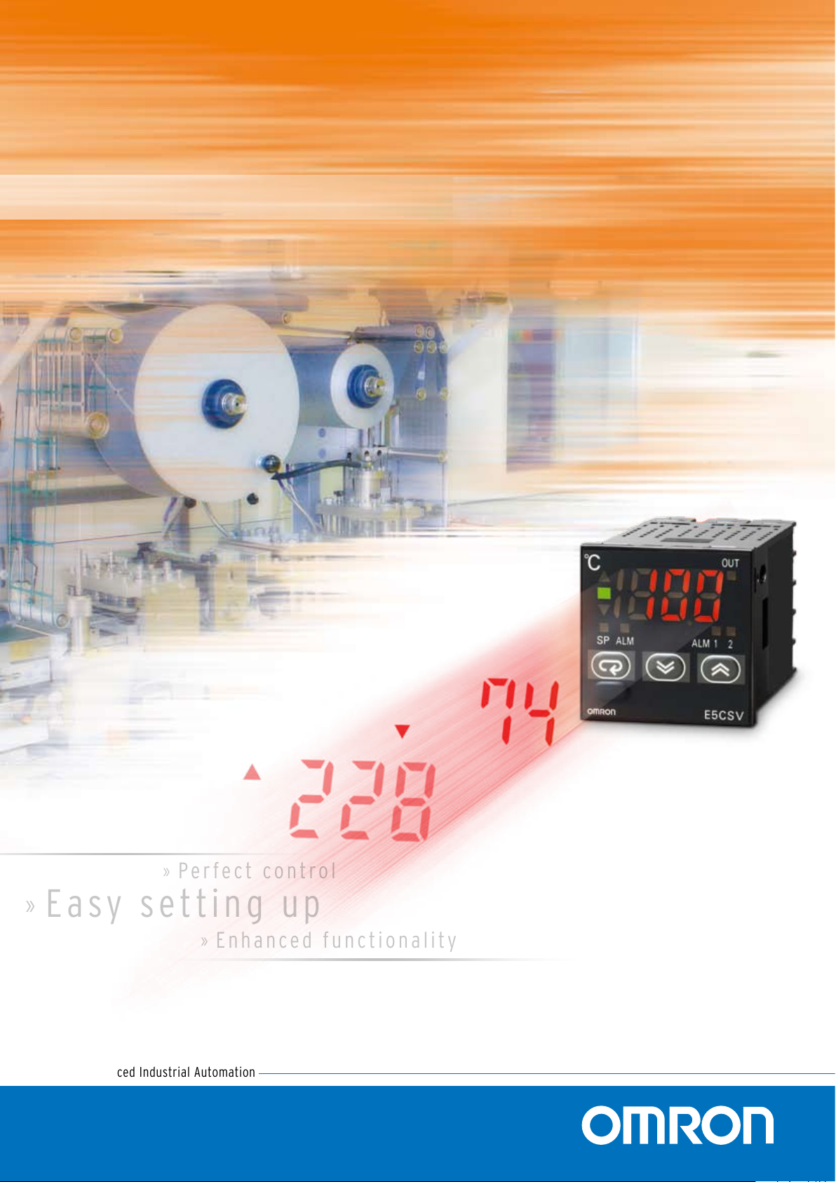
E5CSV temperature controller
R e ad y , s et , g o !
Advanced Industrial Automation
Perfect temperature control
in 4 simple steps
The E5CSV temperature-controller
series is the enhanced successor to our E5CS series,
the most widely sold temperature-controller that has
established itself throughout the world as the ideal
choice for simple, cost-effective temperature control.
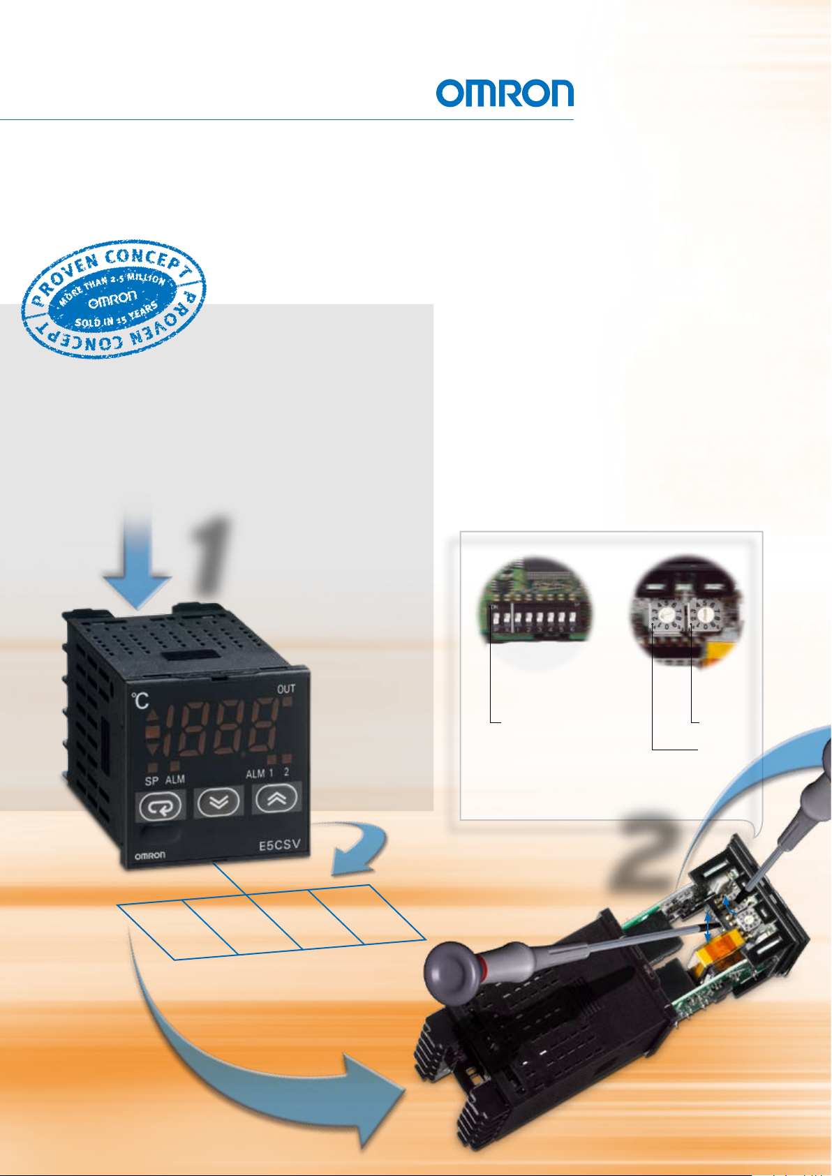
Se l ec t
1
Keeping the best…
The new series shares many of the outstanding features that
made its predecessor such a success – including easy setting-
up using DIP and rotary switches, a large 7-segment LED
display and choice of ON/OFF or PID control with Self-Tuning.
What’s more, it still provides an indication of output and alarm
status and direction of deviation from set point.
Functional
set-up
P SV protection
SW1 ON/OFF - PID control
SW2 fast or slow process
SW3 Heat or Cool
SW4 Input shift ON - OFF
SW5 Thermocouple or RTD
SW6 Celsius or Fahrenheit
Input type
range
Alarm modes
100-240 VAC
Relay
output
Voltage
(puls)
output
24 VAC/VDC
Relay
output
Se t- u p
2
Voltage
(puls)
output
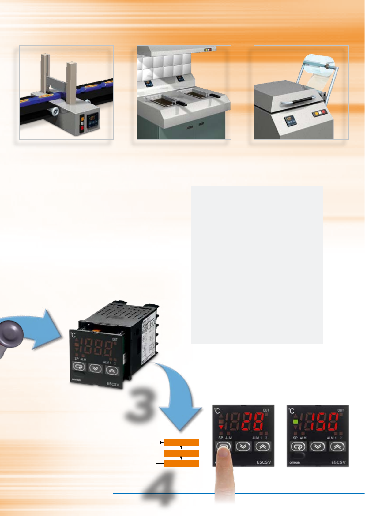
Packing
Excellent control, especially in this disturbance-
sensitive application.
Frying
The flat front makes the use of the E5CSV
hygienic and it’s easy and safe to clean thanks
to its IP66 rating.
Sealing
Clear indication that the correct temperature has
been reached thanks to the deviation indicator.
Enhancing the rest…
Building on the success of the previous E5CS, however, the
new E5CSV series offers much more. Like an Auto-Tune function
and the fact that as standard you can now select multiple input
types (thermocouple/RTD). A new 3.5 digit display also means
that E5CSV can show a larger range, now extending up to
1999 °C.The series also meets new RoHS requirements and
complies with the stringent IP66 standard. What’s more, depth
has been reduced to a mere 78 mm.
Benefits of E5CSV temperature controllers:
• Easy setting-up using DIP and rotary switches
• Meets broad range of basic temperature-control
requirements with only 4 models
• No expert knowledge needed to optimise performance
because of Self- and Auto-Tuning functions
• Reduced chance of malfunction thanks to
set-value protection
• End-user friendly since the menu only has 3 parameters
• Excellent legibility with a large (13.5 mm) single-line,
3.5 digit, 7 segment LED display
• Clear status overview thanks to PV-SV deviation indicator,
output and alarm indicator
• Easy connection to a broad range of temperature-
sensor types
>> Ready.. .
Advanced Industrial Automation
>> Se t. ..
>> Go !
Mo u n t
3
PV
SP
Alarm value
Ad j us t
4
2 Temperature Controllers E5CSV
Specifications
■ Ratings
■ Characteristics
Note: 1. The following exceptions apply to thermocouples.
• U, L: ±2°C ±1 digit max.
• R: ±3° C ±1 digit max. at 200° C or less
2. The following exceptions apply to platinum resistance
thermometers.
Input set values 0, 1, 2, 3 for E5CSV: 0.5% FS ±1 digit max.
Input set value 1 for E5CSV: 0.5% FS ±1 digit max.
Supply voltage 100 to 240 VAC, 50/60 Hz 24 VAC/VDC, 50/60 Hz
Operating voltage range 85% to 110% of rated supply voltage
Power consumption 5 VA 3 VA/2 W
Sensor input Multi-input (thermocouple/platinum resistance thermometer) type: K, J, L, T, U, N, R, Pt100, JPt100
Control
output
Relay output SPST-NO, 250 VAC, 3A (resistive load)
Voltage output (for driving the SSR) 12 VDC, 21 mA (with short-circuit protection circuit)
Control method ON/OFF or 2-PID (with auto-tuning)
Alarm output SPST-NO, 250 VAC, 1A (resistive load)
Setting method Digital setting using front panel keys (functionality set-up with DIP switch)
Indication method 3.5 digit, 7-segment digital display (character height: 13.5 mm) and deviation indicators
Other functions • Setting change prohibit (key protection)
• Input shift
• Temperature unit change (° C/° F)
• Direct/reverse operation
• Control period switching
• 8-mode alarm output
• Sensor error detection
Ambient temperature -10 to 55° C (with no condensation or icing)
Ambient humidity 25% to 85%
Storage temperature -25 to 65° C (with no condensation or icing)
Setting accuracy Thermocouple (See note 1.): (±0.5% of indication value or ±1°C, whichever is greater) ±1 digit max.
Platinum resistance thermometer (See note 2.): (±0.5% of indication value or ±1° C, whichever is greater) ±1 digit max.
Indication accuracy
(ambient temperature of 23° C)
Influence of temperature R thermocouple inputs: (±1% of PV or ±10° C, whichever is greater) ±1 digit max.
Other thermocouple inputs: (±1% of PV or ±4° C, whichever is greater) ±1 digit max.
Platinum resistance thermometer inputs: (±1% of PV or ±2° C, whichever is greater) ±1 digit max.
Influence of voltage
Hysteresis (for ON/OFF control) 0.1% FS
Proportional band (P) 1 to 999° C (automatic adjustment using auto-tuning/self-tuning)
Integral time (I) 1 to 1,999 s (automatic adjustment using auto-tuning/self-tuning
Derivative time (D) 1 to 1,999 s (automatic adjustment using auto-tuning/self-tuning)
Alarm output range Absolute-value alarm: Same as the control range
Other: 0% to 100% FS
Alarm hysteresis: 0.2° C or ° F (fixed)
Control period 2/20 s
Sampling period 500 ms
Insulation resistance 20 MΩ min. (at 500 VDC)
Dielectric strength
2,000 VAC, 50/60 Hz for 1 min between current-carrying terminals of different polarity
Vibration
resistance
Malfunction
10 to 55 Hz, 20 m/s
2
for 10 min each in X, Y, and Z directions
Destruction 10 to 55 Hz, 0.75-mm single amplitude for 2 hr each in X, Y, and Z directions
Shock resistance Malfunction
100 m/s
2
min., 3 times each in 6 directions
Destruction
300 m/s
2
min., 3 times each in 6 directions
Life expectancy Electrical 100,000 operations min. (relay output models)
Weight Approx. 120 g (Controller only)
Degree of protection Front panel: Equivalent to IP66; Rear case: IP20; Terminals: IP00
Memory protection EEPROM (non-volatile memory) (number of writes: 1,000,000)
EMC EMI Radiated: EN 55011 Group 1 Class A
EMI Conducted: EN 55011 Group 1 Class A
ESD Immunity: EN 61000-4-2: 4 kV contact discharge (level 2)
8 kV air discharge (level 3)
Radiated Electromagnetic Field Immunity: EN 61000-4-3: 10 V/m (80-1000 MHz, 1.4-2.0 GHz amplitude modulated) (level 3)
10 V/m (900 MHz pulse modulated)
Conducted Disturbance Immunity: EN 61000-4-6: 3 V (0.15 to 80 MHz) (level 2)
Noise Immunity (First Transient Burst Noise): EN 61000-4-4
Burst Immunity: 2 kV power-line (level 3), 1 kV I/O signal-line (level 3)
Surge Immunity: EN 61000-4-5: Power line: Normal mode 1 kV; Common mode 2 kV
Output line (relay output): Normal mode 1 kV; Common mode 2 kV
Voltage Dip/Interrupting Immunity: EN 61000-4-11 0.5 cycle, 100% (rated voltage)
Approved standards UL 61010C-1 (listing), CSA C22.2 No.1010-1
Conformed standards EN 61326, EN 61010-1, IEC 61010-1, VDE 0106 Part 100 (finger protection), when the terminal cover is mounted.
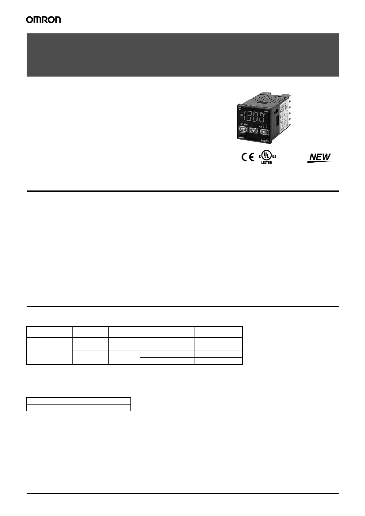
Temperature Controllers
E5CSV
Easy Setting Using DIP Switch and Simple
Functions in DIN 48 x 48 mm-size
Temperature Controllers
• Easy setting using DIP and rotary switches.
• Multi-input (thermocouple/platinum resistance thermometer).
• Clearly visible digital display with character height of 13.5 mm.
• RoHS compliant.
Model Number Structure
■ Model Number Legend
Models with Terminal Blocks
E5CSV-@ 1 T @ -500
1. Output type
2. Number of alarms
Ordering Information
■ List of Models
1/16 DIN
48 x 48 x 78 mm
(W x H x D)
■ Accessories (Order Separately)
Protective Front Cover
Hard Protective Cover Y92A-48B
1 2 3 4 5
R: Relay
Q: Voltage for driving SSR
1: 1 alarm
Size Power supply
Type Model
100 to 240 VAC 1 Relay E5CSV-R1T-500
24 VAC/VDC 1 Relay E5CSV-R1TD-500
3. Input type
T: Thermocouple/platinum resistance
thermometer (multi-input)
voltage
Number of
alarm points
Control output TC/Pt multi-input
Voltage (for driving SSR) E5CSV-Q1T-500
Voltage (for driving SSR) E5CSV-Q1TD-500
4. Power supply voltage
Blank: 100 to 240 VAC
D: 24 VAC/VDC
5. Terminal cover
500: Finger protection cover
Incl. terminal cover
4 Temperature Controllers E5CSV
Temperature Controllers E5CSV 1

Specifications
■ Ratings
Supply voltage 100 to 240 VAC, 50/60 Hz 24 VAC/VDC, 50/60 Hz
Operating voltage range 85% to 110% of rated supply voltage
Power consumption 5 VA 3 VA/2 W
Sensor input Multi-input (thermocouple/platinum resistance thermometer) type: K, J, L, T, U, N, R, Pt100, JPt100
Control
output
Control method ON/OFF or 2-PID (with auto-tuning)
Alarm output SPST-NO, 250 VAC, 1A (resistive load)
Setting method Digital setting using front panel keys (functionality set-up with DIP switch)
Indication method 3.5 digit, 7-segment digital display (character height: 13.5 mm) and deviation indicators
Other functions • Setting change prohibit (key protection)
Ambient temperature -10 to 55° C (with no condensation or icing)
Ambient humidity 25% to 85%
Storage temperature -25 to 65° C (with no condensation or icing)
■ Characteristics
Setting accuracy Thermocouple (See note 1.): (±0.5% of indication value or ±1°C, whichever is greater) ±1 digit max.
Indication accuracy
(ambient temperature of 23° C)
Influence of temperature R thermocouple inputs: (±1% of PV or ±10° C, whichever is greater) ±1 digit max.
Influence of voltage
Hysteresis (for ON/OFF control) 0.1% FS
Proportional band (P) 1 to 999° C (automatic adjustment using auto-tuning/self-tuning)
Integral time (I) 1 to 1,999 s (automatic adjustment using auto-tuning/self-tuning
Derivative time (D) 1 to 1,999 s (automatic adjustment using auto-tuning/self-tuning)
Alarm output range Absolute-value alarm: Same as the control range
Control period 2/20 s
Sampling period 500 ms
Insulation resistance 20 MΩ min. (at 500 VDC)
Dielectric strength
Vibration
resistance
Shock resistance Malfunction
Life expectancy Electrical 100,000 operations min. (relay output models)
Weight Approx. 120 g (Controller only)
Degree of protection Front panel: Equivalent to IP66; Rear case: IP20; Terminals: IP00
Memory protection EEPROM (non-volatile memory) (number of writes: 1,000,000)
EMC EMI Radiated: EN 55011 Group 1 Class A
Approved standards UL 61010C-1 (listing), CSA C22.2 No.1010-1
Conformed standards EN 61326, EN 61010-1, IEC 61010-1, VDE 0106 Part 100 (finger protection), when the terminal cover is mounted.
Note: 1. The following exceptions apply to thermocouples.
Relay output SPST-NO, 250 VAC, 3A (resistive load)
Voltage output (for driving the SSR) 12 VDC, 21 mA (with short-circuit protection circuit)
• Input shift
• Temperature unit change (° C/° F)
• Direct/reverse operation
• Control period switching
• 8-mode alarm output
• Sensor error detection
Platinum resistance thermometer (See note 2.): (±0.5% of indication value or ±1° C, whichever is greater) ±1 digit max.
Other thermocouple inputs: (±1% of PV or ±4° C, whichever is greater) ±1 digit max.
Platinum resistance thermometer inputs: (±1% of PV or ±2° C, whichever is greater) ±1 digit max.
Other: 0% to 100% FS
Alarm hysteresis: 0.2° C or ° F (fixed)
2,000 VAC, 50/60 Hz for 1 min between current-carrying terminals of different polarity
Malfunction
Destruction 10 to 55 Hz, 0.75-mm single amplitude for 2 hr each in X, Y, and Z directions
Destruction
• U, L: ±2°C ±1 digit max.
• R: ±3° C ±1 digit max. at 200° C or less
2. The following exceptions apply to platinum resistance
thermometers.
Input set values 0, 1, 2, 3 for E5CSV: 0.5% FS ±1 digit max.
Input set value 1 for E5CSV: 0.5% FS ±1 digit max.
10 to 55 Hz, 20 m/s
2
min., 3 times each in 6 directions
100 m/s
2
300 m/s
min., 3 times each in 6 directions
EMI Conducted: EN 55011 Group 1 Class A
ESD Immunity: EN 61000-4-2: 4 kV contact discharge (level 2)
Radiated Electromagnetic Field Immunity: EN 61000-4-3: 10 V/m (80-1000 MHz, 1.4-2.0 GHz amplitude modulated) (level 3)
Conducted Disturbance Immunity: EN 61000-4-6: 3 V (0.15 to 80 MHz) (level 2)
Noise Immunity (First Transient Burst Noise): EN 61000-4-4
Burst Immunity: 2 kV power-line (level 3), 1 kV I/O signal-line (level 3)
Surge Immunity: EN 61000-4-5: Power line: Normal mode 1 kV; Common mode 2 kV
Voltage Dip/Interrupting Immunity: EN 61000-4-11 0.5 cycle, 100% (rated voltage)
2
for 10 min each in X, Y, and Z directions
8 kV air discharge (level 3)
10 V/m (900 MHz pulse modulated)
Output line (relay output): Normal mode 1 kV; Common mode 2 kV
2 Temperature Controllers E5CSV
5Temperature Controllers E5CSV

E5CSV
4 Temperature Controllers E5CSV
Operation
E5CSV
Settings before Turning ON the Power
E5CSV
Remove the E5CSV from the case to make the settings.
1. Insert the tool into the two tool insertion holes (one on the top and
one on the bottom) and release the hooks.
2. Insert the tool in the gap between the front panel and rear case,
and pull out the front panel slightly. Grip the front panel and pull
out fully. Be sure not to impose excessive force on the panel.
3. When inserting the E5CSV, check to make sure that the sealing
rubber is in place and push the E5CSV toward the rear case until
it snaps into position. While pushing the E5CSV into place, push
down on the hooks on the top and bottom surfaces of the rear
case so that the hooks are securely locked in place. Make sure
that electronic components do not come into contact with the
case.
Note: 1. The INIT switch is always OFF during normal operation.
Deviation indicators
The indicator lights when the PV is greater than
the SP and the indicator lights when the PV is
less than the SP. The indicator (green) lights
when the deviation is less than 1% FS (0.25% FS
for multi-input models). These indicators flash
during ST (self-tuning)/AT (auto-tuning).
Mode indicators
The SP indicator lights when the setting
temperature is being displayed. The ALM
indicator lights when the alarm value 1 is
being displayed.
PV, SP, Alarm Value, Input Shift Display
Alarm indicators
ALM1 (Alarm 1): Lights when the alarm 1
output is ON.
ALM2 (Alarm 2): For future use.
Up Key
Pressing the Up Key increases the
SP/alarm value display. Keeping the Up
Key pressed continues to increase the
display value. When the internal protect
switch is ON, press the Up Key while
holding down the Lock Release Key.
Output indicator
Lights when the control output is ON.
The display switches each time the
Key is pressed.
Lock Release Key
When the protect switch is ON, the set
value can be changed by pressing the Up
and Down Keys while holding down the
Lock Release Key.
Down Key
Pressing the Down Key decreases the
SP/alarm value display. Keeping the Down
Key pressed continues to decrease the
display value. When the internal protect
switch is ON, press the Down Key while
holding down the Lock Release Key.
When the power is turned ON, normally the
display will use the display items in the following
order each time the Mode Key is pressed.
Mode Key
PV
SP
Alarm value 1
Input shift value
Power ON
Press the Key.
Press the Key.
Press the Key.
Press the Key.
This item is not displayed when
the Control Mode Switch 4 is OFF.
Flat-blade screwdriver
(Unit: mm)
(1)
(1)
(2)
(3)
Tool insertion hole
0.4 2.0
20 min.
PONX 1 2 3 4 5 6
Alarm mode switch (See note 1.)
Temperature range switch
Control mode switches
INIT switch
(See note 2.)
Protect switch
ON
Installation
• All models in the E5CSV Series conform to DIN 43700 standards.
• The recommended panel thickness is 1 to 4 mm.
• Be sure to mount the E5CSV horizontally.
Mounting the E5CSV
1. For waterproof mounting, waterproof packing must be installed on the Controller. Waterproofing is not possible when group mounting several
Controllers.
2. Insert the E5CSV into the mounting hole in the panel.
3. Push the adapter from the terminals up to the panel, and temporarily fasten the E5CSV.
4. Tighten the two fastening screws on the adapter. Alternately tighten the two screws little by little to maintain a balance. Tighten the screws to a
torque of 0.29 to 0.39 N·m.
Dimensions
Note: All units are in millimeters unless otherwise indicated.
■ Controller
Hard Protective Cover
The Y92A-48B Protective Cover (hard type) is
available for the following applications.
°
C
• To protect the set from dust and dirt.
48×48
Note: Terminals cannot be removed.
• To prevent the panel from being accidentally
92A -48 B
92A -48 B
touched causing displacement of set values.
• To provide effective protection against water
droplets.
Voltage output
models
(See note 1.)
12 VDC,
21 mA
A
B
B
Platinum resistance
thermometer input
platinum resistance thermometer multi-input
2
3
4
5
Thermocouple/
Relay output
models
Relay outputVoltage output
11
1
2
2
3
4
5
Thermocouple
input
Alarm output
6
7
Alarm output 1
8
9
100 to 240 VAC, 50/60 Hz
(24 VAC/VDC)
(See note 2.)
10
Note: 1. The voltage output (12 VDC, 21 mA) is not electrically isolated from the internal circuits. When using a grounding thermocouple, do not
84
786
58
Terminal Cover
E53-COV10
44.8×44.8
Adapter for flush mounting
48
Note: 1. The recommended panel thickness is 1 to 4 mm.
2. Group mounting is possible in one direction only.
Panel Cutout Dimensions
+0.6
45
0
+0.6
45
0
60 min.
7.5
48.8
22
9.1
+0.6
45
0
L = (48 × N−2.5)
Mounting side-by-side
(group mounting of N Controllers)
Y92F-30 Adapter for flush mounting
Panel
Tightening
screws
76.5
48
L
+1
0
connect output terminals 1 or 2 to ground. Otherwise, unwanted current paths will cause measurement errors.
2. Models with 100 to 240 VAC and 24 VAC/VDC are separate. Models using 24 VDC have no polarity.
6 Temperature Controllers E5CSV
Temperature Controllers E5CSV 3

Operation
E5CSV
Deviation indicators
The indicator lights when the PV is greater than
the SP and the indicator lights when the PV is
less than the SP. The indicator (green) lights
when the deviation is less than 1% FS (0.25% FS
for multi-input models). These indicators flash
during ST (self-tuning)/AT (auto-tuning).
Mode indicators
The SP indicator lights when the setting
temperature is being displayed. The ALM
indicator lights when the alarm value 1 is
being displayed.
Mode Key
When the power is turned ON, normally the
display will use the display items in the following
order each time the Mode Key is pressed.
Power ON
PV
Press the Key.
SP
Press the Key.
Alarm value 1
Press the Key.
Input shift value
Press the Key.
This item is not displayed when
the Control Mode Switch 4 is OFF.
Lock Release Key
When the protect switch is ON, the set
value can be changed by pressing the Up
and Down Keys while holding down the
Lock Release Key.
PV, SP, Alarm Value, Input Shift Display
The display switches each time the
Key is pressed.
Output indicator
Lights when the control output is ON.
Alarm indicators
ALM1 (Alarm 1): Lights when the alarm 1
output is ON.
ALM2 (Alarm 2): For future use.
Up Key
Pressing the Up Key increases the
SP/alarm value display. Keeping the Up
Key pressed continues to increase the
display value. When the internal protect
switch is ON, press the Up Key while
holding down the Lock Release Key.
Down Key
Pressing the Down Key decreases the
SP/alarm value display. Keeping the Down
Key pressed continues to decrease the
display value. When the internal protect
switch is ON, press the Down Key while
holding down the Lock Release Key.
Settings before Turning ON the Power
E5CSV
Remove the E5CSV from the case to make the settings.
1. Insert the tool into the two tool insertion holes (one on the top and
one on the bottom) and release the hooks.
Tool insertion hole
Flat-blade screwdriver
(Unit: mm)
20 min.
0.4 2.0
(3)
(2)
(1)
(1)
2. Insert the tool in the gap between the front panel and rear case,
and pull out the front panel slightly. Grip the front panel and pull
out fully. Be sure not to impose excessive force on the panel.
3. When inserting the E5CSV, check to make sure that the sealing
rubber is in place and push the E5CSV toward the rear case until
it snaps into position. While pushing the E5CSV into place, push
down on the hooks on the top and bottom surfaces of the rear
case so that the hooks are securely locked in place. Make sure
that electronic components do not come into contact with the
case.
Control mode switches
ON
PONX 1 2 3 4 5 6
Note: 1. The INIT switch is always OFF during normal operation.
INIT switch
(See note 2.)
Protect switch
Alarm mode switch (See note 1.)
Temperature range switch
4 Temperature Controllers E5CSV
7Temperature Controllers E5CSV

1. Sensor Type Specification
6 Temperature Controllers E5CSV
2. Operation Settings
Use the control mode switches ( ) to change the
control mode. (All switches are OFF for the default settings.)
Note: The previous name Pt100 has been changed to JPt100 in
accordance with revisions to JIS. The previous name J-DIN has
been changed to L in accordance with revisions to DIN
standards.
3. Alarm Modes
Select the number of the alarm mode switch when changing
the alarm mode. (The default is 2).
Note: 1. No alarm. The alarm value (alarm operation display) will not
be displayed when the setting is 0 or 9 even if the selection
key is pressed.
Alarm Setting Range
X: 0 to FS (full scale); Y: Within temperature range
The value of X is the deviation setting for the SP (set point).
2. Standby Sequence Function (The standby sequence
operates when the power is turned ON.)
For details on the position of the temperature range switch, control mode switches, and alarm mode switch, refer to page 4.
Function selection 1 2 3 4 5 6
ON/OFF
PID
PID control
ON
ON/OFF control
OFF
Control
period
2 s
ON
20 s
OFF
Direct/
reverse
opera-
tion
Direct operation
(cooling)
ON
Reverse operation
(heating)
OFF
Input
shift
display
Enabled
ON
Disabled
OFF
Tempera-
ture
Sensor
selection
Platinum
resistance thermometer
input
ON
Thermocouple
input
OFF
Temper-
ature
unit
° F
ON
° C
OFF
654321
ON
654321
ON
Set
value
Alarm type Alarm output operation
0, 9 Alarm function OFF OFF
1
Upper- and lower-
limit
2
Upper-limit
3
Lower-limit
4
Upper- and lower-
limit range
5
Upper- and lower-
limit with standby
sequence (See note
2.)
6
Upper-limit with
standby sequence
(See note 2.)
7
Lower-limit with
standby sequence
(See note 2.)
8
Absolute-value
upper-limit
0
1
2
3
4
5
6
7
8
9
XSPX
ON
OFF
SP
X
ON
OFF
X
SP
ON
OFF
XSPX
ON
OFF
XSPX
ON
OFF
X
SP
ON
OFF
X
SP
ON
OFF
0
Y
ON
OFF
Upper-limit
alarm
SP
Lower-limit
alarm
Alarm
output
ON
OFF
Upper-limit
alarm
SP
Lower-limit
alarm
Alarm
output
ON
OFF
Rising Temperature
Dropping Temperature
Note: Turn OFF the power before changing the DIP switch settings on the E5CSV. Each of the switch settings will be enabled after the power is
turned ON.
Multi-input (Thermocouple/Platinum
Resistance Thermometer) Models
• Using Thermocouple Sensors, Control Mode Switch 5: OFF
Input K J L T U N R
1,700
1,600
1,500
1,400
1,300 1,300
1,300
1,200
1,100
SP
range
Setting number
• The control range is -20° C to +20° C of the input temperature
range.
Note: 1. The input indication range is the range that can be displayed for
• Using Platinum Resistance Thermometers,
Control Mode Switch 5: ON
SP
range
Setting number
1,000
900
800
700
600
500
400
300
200
100
-100
199.9 199.9 199.9
0
0.0 0.0 0.0 0
-99 -99 -99 -99 -99 -99
0 1 2 3 4 5 6 7 8 9
the control range (-99 to 1999). If the input is within the control
range but exceeds the display range (-99 to 1999), values below
-99 will be displayed as “[[[“ and values above 1,999 will be
displayed as “]]].”
2. If unit is changed to 1 degree when the SP and alarm value for
the temperature range are displayed in 0.1-units from 0.0 to
199.9 or 0.0 to 99.9, the values will be multiplied by 10 (e.g., 0.5
becomes 5). If the unit is changed in the reverse direction, the
values will be divided by 10. After changing the range, set the
SP and alarm value again.
Input Pt100 JPt100
1,000
850
900
800
700
600
500
400
300
200
100
-100
199.9 200 199.9 200
0
0.0 0 0 0.0 0 0
-99 -99 -99 -99
0 1 2 3 4 5 6 7 8 9
• The control range is -20° C to +20° C of the input temperature
range.
Note: 1. The input indication range is the range that can be displayed for
Mode Key Display Order
the control range (-99 to 1999). If the input is within the control
range but exceeds the display range (-99 to 1999), values below
-99 will be displayed as “[[[“ and values above 1,999 will be
displayed as “]]].”
2. If unit is changed to 1 degree when the SP and alarm value for
the temperature range are displayed in 0.1-units from 0.0 to
199.9 or 0.0 to 99.9, the values will be multiplied by 10 (e.g., 0.5
becomes 5). If the unit is changed in the reverse direction, the
values will be divided by 10. After changing the range, set the
SP and alarm value again.
Power ON
1,700
850 850
400 400
500
400 400
99 99
• If the SP falls outside the temperature
range when the temperature range is
ST (Self-tuning) Features
ST (self-tuning) is a function that finds PID constants by using step
response tuning (SRT) when Controller operation begins or when
the set point is changed. Once the PID constants have been
calculated, ST is not executed when the next control operation is
started as long as the set point remains unchanged. When the ST
function is in operation, be sure to turn ON the power supply of the
load connected to the control output simultaneously with or before
starting Controller operation.
Executing AT (Auto-tuning)
AT (auto-tuning) is executed by pressing the U Up and D Down
Keys for at least 2 s while the PV is displayed. The deviation
indicators flash during auto-tuning (AT) execution. AT will be
cancelled by performing the same operation that AT is executing
during AT operation. Flashing stops when AT is completed.
AT execution
AT cancelled
U D
Press for
at least 2 s.
Note: One of the deviation indicators (▲■▼) will flash.
AT execution in progress
■ Electrical Life Expectancy
Curve for Relays (Reference
Values)
500
300
operations)
4
100
10
50
Life (×
30
10
5
E5CSV
250 VAC, 30 VDC
3
(resistive load)
cosφ = 1
1
0 1 2 3 4 5 6
U D
Press for
at least 2 s.
Switching current (A)
AT execution in progress
changed, the SP will be displayed first.
PV
Press the Key.
SP
Press the Key.
Alarm value 1
Press the Key.
Input shift value
Press the Key.
The SP will be changed automatically
either to the minimum value or the
maximum value, whichever is nearest.
• If the alarm value falls outside the
temperature range when the
temperature range is changed, the
alarm value will be displayed first. The
alarm value will be changed
automatically to the maximum value in
the new temperature range.
8 Temperature Controllers E5CSV
Temperature Controllers E5CSV 5

2. Operation Settings
Use the control mode switches ( ) to change the
control mode. (All switches are OFF for the default settings.)
Function selection 1 2 3 4 5 6
ON/OFF
PID
Control
period
Direct/
reverse
operation
Input
shift
display
Temperature
Sensor
selection
Temperature
unit
PID control
ON/OFF control
2 s
20 s
Direct operation
(cooling)
Reverse operation
(heating)
Enabled
Disabled
Platinum
resistance thermometer
input
Thermocouple
input
° F
° C
Note: The previous name Pt100 has been changed to JPt100 in
accordance with revisions to JIS. The previous name J-DIN has
been changed to L in accordance with revisions to DIN
standards.
ON
654321
ON
ON
OFF
ON
OFF
ON
OFF
ON
OFF
ON
OFF
654321
ON
OFF
3. Alarm Modes
0
1
9
2
8
SP
OFF
ON
3
7
4
6
5
XSPX
SP
X
SP
XSPX
XSPX
SP
X
SP
0
X
X
Y
Select the number of the alarm mode switch when changing
the alarm mode. (The default is 2).
Set
Alarm type Alarm output operation
value
0, 9 Alarm function OFF OFF
Upper- and lower-
1
limit
Upper-limit
2
Lower-limit
3
Upper- and lower-
4
limit range
ON
OFF
ON
OFF
ON
OFF
ON
OFF
Upper- and lowerlimit with standby
5
sequence (See note
ON
OFF
2.)
Upper-limit with
6
standby sequence
(See note 2.)
Lower-limit with
7
standby sequence
(See note 2.)
Absolute-value
8
upper-limit
ON
OFF
ON
OFF
ON
OFF
Note: 1. No alarm. The alarm value (alarm operation display) will not
be displayed when the setting is 0 or 9 even if the selection
key is pressed.
Alarm Setting Range
X: 0 to FS (full scale); Y: Within temperature range
The value of X is the deviation setting for the SP (set point).
2. Standby Sequence Function (The standby sequence
operates when the power is turned ON.)
Rising Temperature
Upper-limit
alarm
SP
Lower-limit
alarm
Alarm
ON
output
OFF
Dropping Temperature
Upper-limit
alarm
Lower-limit
alarm
Alarm
output
Note: Turn OFF the power before changing the DIP switch settings on the E5CSV. Each of the switch settings will be enabled after the power is
turned ON.
For details on the position of the temperature range switch, control mode switches, and alarm mode switch, refer to page 4.
6 Temperature Controllers E5CSV
9Temperature Controllers E5CSV

8 Temperature Controllers E5CSV
(2) Using the E5CSV in Devices for Fahrenheit-scale Users
(Displaying in ° F)
Turn ON switch 6 to display temperatures in °F.
Temperature Range for ° F
The temperature is set to ° F using the same temperature range switch as ° C.
Note: The control range for multi-input (thermocouple/platinum resistance thermometer) models is -40 to +40° F of each temperature range.
The previous name J-DIN has been changed to L in accordance with revisions to DIN standards.
(3) Setting Input Shift
Turn ON switch 4, and after turning ON the power, press the Mode
Key until h0 (indicates input shift of 0) is displayed. Press the Up and
Down Keys to set the shift value.
Shift Example
Note: When control mode switch 4 is turned OFF (no input shift
display), the input shift is not displayed but the shift value is
enabled. To disable input shift, set the input shift value to h0.
The shift range depends on the setting unit.
5. Protect Switch
When the protect switch is ON, Up Key and Down Key operations are prohibited to prevent setting mistakes.
654321
ON
Multi-input (Thermocouple/
Platinum Resistance
Thermometer)
Control mode switch 5: OFF
Multi-input (Thermocouple/
Platinum Resistance
Thermometer)
Control mode switch 5: ON
Set-
ting
° F Set-
ting
° F
0 K -99 to 1999 0 Pt100 -99 to 1500
1 0.0 to 199.9 1 0.0 to 199.9
2 J -99 to 1500 2 -99 to 99
3 0.0 to 199.9 3 0 to 200
4 L -99 to 1500 4 0 to 400
5 T -99 to 700 5 JPt100 -99 to 900
6 0.0 to 199.9 6 0.0 to 199.9
7 U -99 to 700 7 -99 to 99
8 N -99 to 1999 8 0 to 200
9 R 0 to 1999 9 0 to 400
654321
ON
Input shift display Measured temperature Temperature
display
h0 (no shift) 100° C 100° C
h9 (+9° C shift) 100° C 109° C
l9 (-9° C shift) 100° C 91°C
Setting unit 1° C 0.1° C
Compensation range -99 to +99° C -9.9 to +9.9° C
Input shift display L99 to H99 L9.9 to H9.9
PONX 1 2 3 4 5 6
Protect Switch
4. Using the Control Mode Switches
(1) Using ON/OFF Control and PID Control
(1.1) ON/OFF Control
The control mode is set to ON/OFF control as the default setting. To perform cooling control of freezers, etc., turn ON switch 3.
ON
ON
SP
654321
ONControl output
OFF
654321
SP
(1.2) PID Control
Turn ON switch 1 to use PID control.
Switch 1 OFF: ON/OFF control
ONControl output
OFF
ON
1. Set the control period.
Performing Control via Relay Output, External Relay, or
Conductor
Switch 2: OFF (control period: 20 s)
Switch 1 ON: PID control
ON
654321
2. Set direct/reverse operation for the output.
Performing Heating Control for Heaters
Switch 3: OFF
ON
SP
SP
654321
Output level
654321
Output level
654321
Quick Control Response Using an SSR
Switch 2: ON (control period: 2 s)
ONControl output
OFF
20 s
ON
654321
ONControl output
OFF
2 s
100%
0%
Performing Cooling Control for Freezers
Switch 3: ON
ON
100%
0%
Temperature Controllers E5CSV 7
Temperature Controllers E5CSV10

(2) Using the E5CSV in Devices for Fahrenheit-scale Users
(Displaying in ° F)
Turn ON switch 6 to display temperatures in °F.
ON
654321
Temperature Range for ° F
The temperature is set to ° F using the same temperature range switch as ° C.
Multi-input (Thermocouple/
Platinum Resistance
Thermometer)
Control mode switch 5: OFF
Setting
0 K -99 to 1999 0 Pt100 -99 to 1500
1 0.0 to 199.9 1 0.0 to 199.9
2 J -99 to 1500 2 -99 to 99
3 0.0 to 199.9 3 0 to 200
4 L -99 to 1500 4 0 to 400
5 T -99 to 700 5 JPt100 -99 to 900
6 0.0 to 199.9 6 0.0 to 199.9
7 U -99 to 700 7 -99 to 99
8 N -99 to 1999 8 0 to 200
9 R 0 to 1999 9 0 to 400
Note: The control range for multi-input (thermocouple/platinum resistance thermometer) models is -40 to +40° F of each temperature range.
The previous name J-DIN has been changed to L in accordance with revisions to DIN standards.
° F Set-
Multi-input (Thermocouple/
Platinum Resistance
Thermometer)
Control mode switch 5: ON
ting
° F
(3) Setting Input Shift
Turn ON switch 4, and after turning ON the power, press the Mode
Key until h0 (indicates input shift of 0) is displayed. Press the Up and
Down Keys to set the shift value.
ON
654321
Shift Example
Input shift display Measured temperature Temperature
h0 (no shift) 100° C 100° C
h9 (+9° C shift) 100° C 109° C
l9 (-9° C shift) 100° C 91°C
Note: When control mode switch 4 is turned OFF (no input shift
display), the input shift is not displayed but the shift value is
enabled. To disable input shift, set the input shift value to h0.
The shift range depends on the setting unit.
Setting unit 1° C 0.1° C
Compensation range -99 to +99° C -9.9 to +9.9° C
Input shift display L99 to H99 L9.9 to H9.9
5. Protect Switch
Protect Switch
PONX 1 2 3 4 5 6
When the protect switch is ON, Up Key and Down Key operations are prohibited to prevent setting mistakes.
display
Temperature Controllers E5CSV 11
8 Temperature Controllers E5CSV

OMRON EUROPE B.V.
Wegalaan 67-69, NL-2132 JD, Hoofddorp, The Netherlands. Tel: +31 (0) 23 568 13 00 Fax: +31 (0) 23 568 13 88 www.omron-industrial.com
Austria
Tel: +43 (0) 1 80 19 00
www.omron.at
Belgium
Tel: +32 (0) 2 466 24 80
www.omron.be
Czech Republic
Tel: +420 234 602 602
www.omron.cz
Denmark
Tel: +45 43 44 00 11
www.omron.dk
Finland
Tel: +358 (0) 207 464 200
www.omron.fi
France
Tel: +33 (0) 1 56 63 70 00
www.omron.fr
Germany
Tel: +49 (0) 2173 680 00
www.omron.de
Hungary
Tel: +36 (0) 1 399 30 50
www.omron.hu
Italy
Tel: +39 02 32 68 1
www.omron.it
Middle East & Africa
Tel: +31 (0) 23 568 11 00
www.omron-industrial.com
Netherlands
Tel: +31 (0) 23 568 11 00
www.omron.nl
Norway
Tel: +47 (0) 22 65 75 00
www.omron.no
Poland
Tel: +48 (0) 22 645 78 60
www.omron.pl
Portugal
Tel: +351 21 942 94 00
www.omron.pt
Russia
Tel: +7 495 745 26 64
www.omron.ru
Spain
Tel: +34 913 777 900
www.omron.es
Sweden
Tel: +46 (0) 8 632 35 00
www.omron.se
Switzerland
Tel: +41 (0) 41 748 13 13
www.omron.ch
Turkey
Tel: +90 (0) 216 474 00 40
www.omron.com.tr
United Kingdom
Tel: +44 (0) 870 752 08 61
www.omron.co.uk
Aut hori sed Dis tri buto r:
KPP_E5CSV_01_EN_INT
Control Systems
• Programmable logic controllers • Human-machine interfaces • Remote I/O
Motion & Drives
• Motion controllers • Servo systems • Inverters
Control Components
• Temperature controllers • Power supplies • Timers • Counters • Programmable relays
• Digital panel indicators • Electromechanical relays • Monitoring products • Solid-state relays
• Limit switches • Pushbutton switches • Low voltage switch gear
Sensing & Safety
• Photoelectric sensors • Inductive sensors • Capacitive & pressure sensors • Cable connectors
• Displacement & width-measuring sensors • Vision systems • Safety networks • Safety sensors
• Safety units/relay units • Safety door/guard lock switches
Although we strive for perfection, Omron Europe BV and/or its subsidiary and affiliated companies do not warrant
or make any representations regarding the correctness or completeness of the information described in this document.
We reserve the right to make any changes at any time without prior notice.
 Loading...