

Omron E3X-MDA11, E3X-MDA6, E3X-MDA41, E3X-MDA8 Datasheet
E3X-MDA Super Dual Fiber Sensors 1
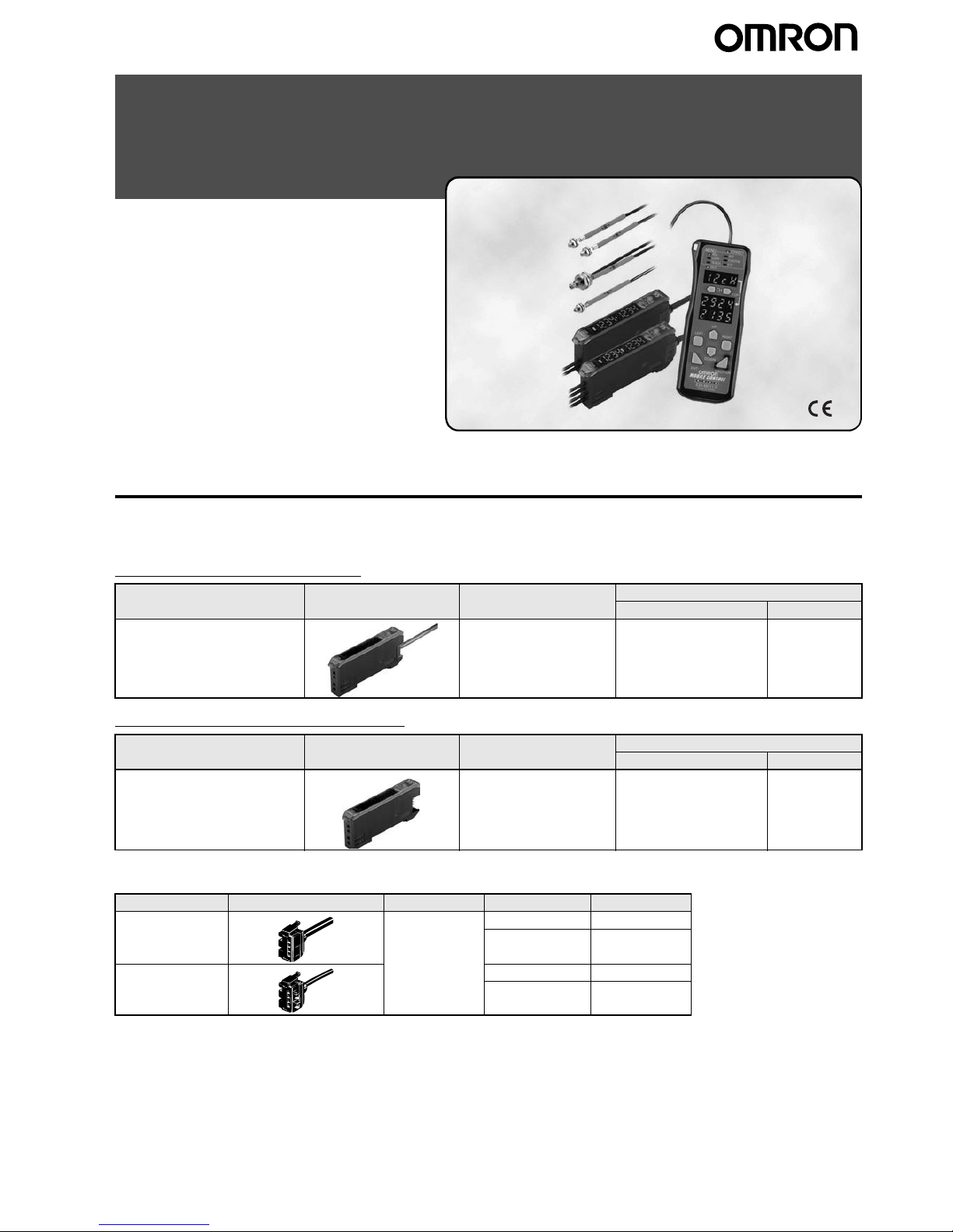
Super Dual Fiber Sensors
E3X-MDA
The remarkable, new-dimension
2-channel amplifiers
• The thinnest profile in the industry, at only 5 mm per
channel.
• AND/OR control output.
• Flexible control from the Mobile Console.
<READ AND UNDERSTAND THIS CATALOG>
Please read and understand this catalog before purchasing
the products. Please consult your OMRON representative if
you have any questions or comments.
Ordering Information
■ Amplifier Units
Amplifier Units with Cables
Amplifier Units with Connectors
■ Amplifier Unit Connectors (Order Separately)
Item Appearance Functions Model
NPN output PNP output
2-channel models AND/OR output E3X-MDA11 E3X-MDA41
Item Appearance Functions Model
NPN output PNP output
2-channel models AND/OR output E3X-MDA6 E3X-MDA8
Item Appearance Cable length No. of conductors Model
Master Connector 2 m 3 E3X-CN11
4 E3X-CN21
Slave Connector 1 E3X-CN12
2 E3X-CN22
2 E3X-MDA Super Dual Fiber Sensors
Combining Amplifier Units and Connectors
Amplifier Units and Connectors are sold separately. Refer to the following tables when placing an order.
When Using 5 Amplifier Units
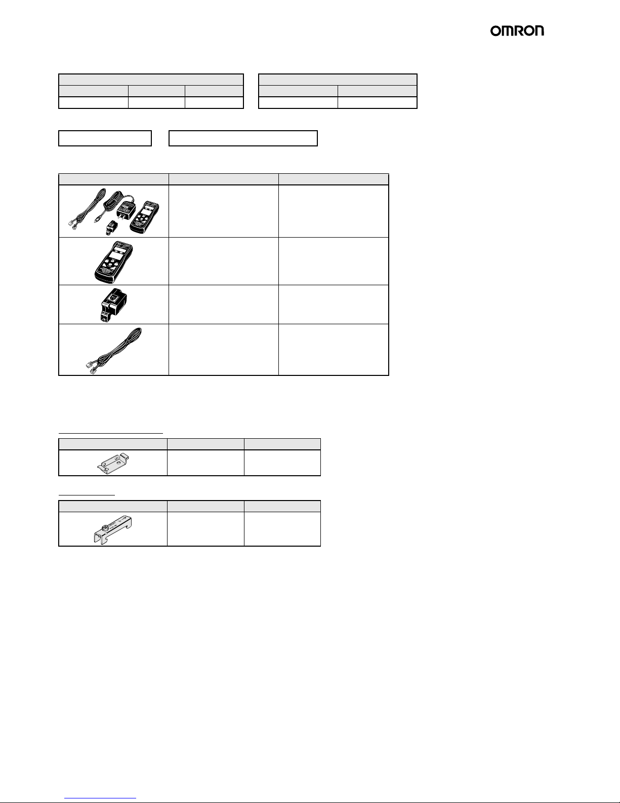
■ Mobile Console (Order Separately)
Note:Use the E3X-MC11-S Mobile Console for the E3X-DA-S/MDA-series Amplifier Units. Other Mobile Consoles cannot be used.
■ Accessories (Order Separately)
Mounting Bracket
End Plate
Amplifier Unit Applicable Connector (Order Separately)
Model NPN output PNP output Master Connector Slave Connector
2-channel models E3X-MDA6 E3X-MDA8 + E3X-CN21 (4-wire) E3X-CN22 (2-wire)
Amplifier Units (5 Units)
+
1 Master Connector + 4 Slave Connectors
Appearance Model Remarks
E3X-MC11-S
(model number of set)
Mobile Console with Head, Cable, and AC adapter provided as
accessories
E3X-MC11-C1-S Mobile Console
E3X-MC11-H1 Head
E39-Z12-1 Cable (1.5 m)
Appearance Model Quantity
E39-L143 1
Appearance Model Quantity
PFP-M 1
E3X-MDA Super Dual Fiber Sensors 3
Specifications
■ Ratings/Characteristics
Amplifier Units
*1: When differential output is selected for the output setting, the second channel output is 200 µs for operation and reset respectively.
*2: Communications are disabled if the detection mode is selected during super-high-speed mode, and the communications functions for mutual
interference prevention and the Mobile Console will not function.
*3: Mutual interference prevention can be used for up to 5 Units (10 channels) if power tuning is enabled.
Type 2-channel models
Model NPN output E3X-MDA11 E3X-MDA6
Item PNP output E3X-MDA41 E3X-MDA8
Light source (wavelength) Red LED (635 nm)
Supply voltage 12 to 24 VDC
±10%, ripple (p-p) 10% max.
Power consumption 1,080 mW max.
(current consumption: 45 mA max. at power supply voltage of 24 VDC)
Control output Load power supply voltage: 26.4 VDC; open collector;
load current: 50 mA max.; residual voltage: 1 V max.
Circuit protection Reverse polarity for power supply connection, output short-circuit
Response
time
Superhighspeed
mode
NPN 130
µs
*1
for operation and reset respectively
PNP
Standard mode 1 ms for operation and reset respectively
High-resolution mode 4 ms for operation and reset respectively
Sensitivity setting Teaching or manual method
Functions Power tuning Light emission power and reception gain, digital control method
Timer function Select from OFF-delay, ON-delay, or one-shot timer.
1 ms to 5 s (1 to 20 ms set in 1-ms increments, 20 to 200 ms set in 10-ms increments,
200 ms to 1 s set in 100-ms increments, and 1 to 5 s set in 1 s-increments)
Automatic power control
(APC)
High-speed control method for emission current
Zero-reset Display can be reset to zero when required (negative values can be displayed).
Initial reset Settings can be returned to defaults as required.
Mutual interference
prevention
Possible for up to 9 Units (18 channels)
*2, *3
I/O settings Output setting (Select from channel 2 output, AND, OR, leading edge sync, falling edge sync, or differ-
ential output)
Display Operation indicator for channel 1 (orange), Operation indicator for channel 2 (orange)
Digital display Select from the following: Incident level for channel 1 + incident level for channel 2, Incident level +
threshold, incident level percentage + threshold, incident light peak level + no incident light bottom level,
minimum incident light peak level + maximum no incident light bottom level, long bar display, incident
level + peak hold, incident level + channel
Display orientation Switching between normal/reversed display is possible.
Ambient illumination
(receiver side)
Incandescent lamp: 10,000 lux max.
Sunlight: 20,000 lux max.
Ambient temperature Operating: Groups of 1 to 2 Amplifiers:
−25°C to 55°C
Groups of 3 to 10 Amplifiers:
−25°C to 50°C
Groups of 11 to 16 Amplifiers:
−25°C to 45°C
(with no icing or condensation)
Storage:
−30°C to 70°C (with no icing or condensation)
Ambient humidity Operating and storage: 35% to 85% (with no condensation)
Insulation resistance 20 M
Ω min. (at 500 VDC)
Dielectric strength 1,000 VAC at 50/60 Hz for 1 minute
Vibration resistance (destruction) 10 to 55 Hz with a 1.5-mm double amplitude for 2 hrs each in X, Y and Z directions
Shock resistance (destruction) 500 m/s
2
, for 3 times each in X, Y and Z directions
Enclosure rating IEC 60529 IP50 (with Protective Cover attached)
Connection method Prewired cable Standard connector
Weight (packed state) Approx. 100 g Approx. 55 g
Materials Case Polybutylene terephthalate (PBT)
Cover Polycarbonate (PC)
Accessories Instruction sheet
4 E3X-MDA Super Dual Fiber Sensors
Amplifier Unit Connectors
Mobile Console
Item E3X-CN11/21/22 E3X-CN12
Rated current 2.5 A
Rated voltage 50 V
Contact resistance 20 m
Ω max. (20 mVDC max., 100 mA max.)
(The figure is for connection to the Amplifier Unit and the adjacent Connector. It does not include the conductor resistance
of the cable.)
No. of insertions
(destruction)
50 times
(The figure for the number of insertions is for connection to the Amplifier Unit and the adjacent Connector.)
Materials Housing Polybutylene terephthalate (PBT)
Contacts Phosphor bronze/gold-plated nickel
Weight (packed state) Approx. 55 g Approx. 25 g
Item E3X-MC11-S
Supply voltage Charged with AC adapter
Connection method Connected via adapter
Weight (packed state) Approx. 580 g (Console only: 120 g)
Refer to Operation Manual provided with the Mobile Console for details.
E3X-MDA Super Dual Fiber Sensors 5
Ordering Information: Fiber Units
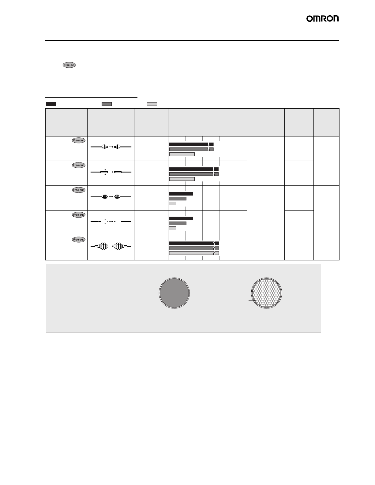
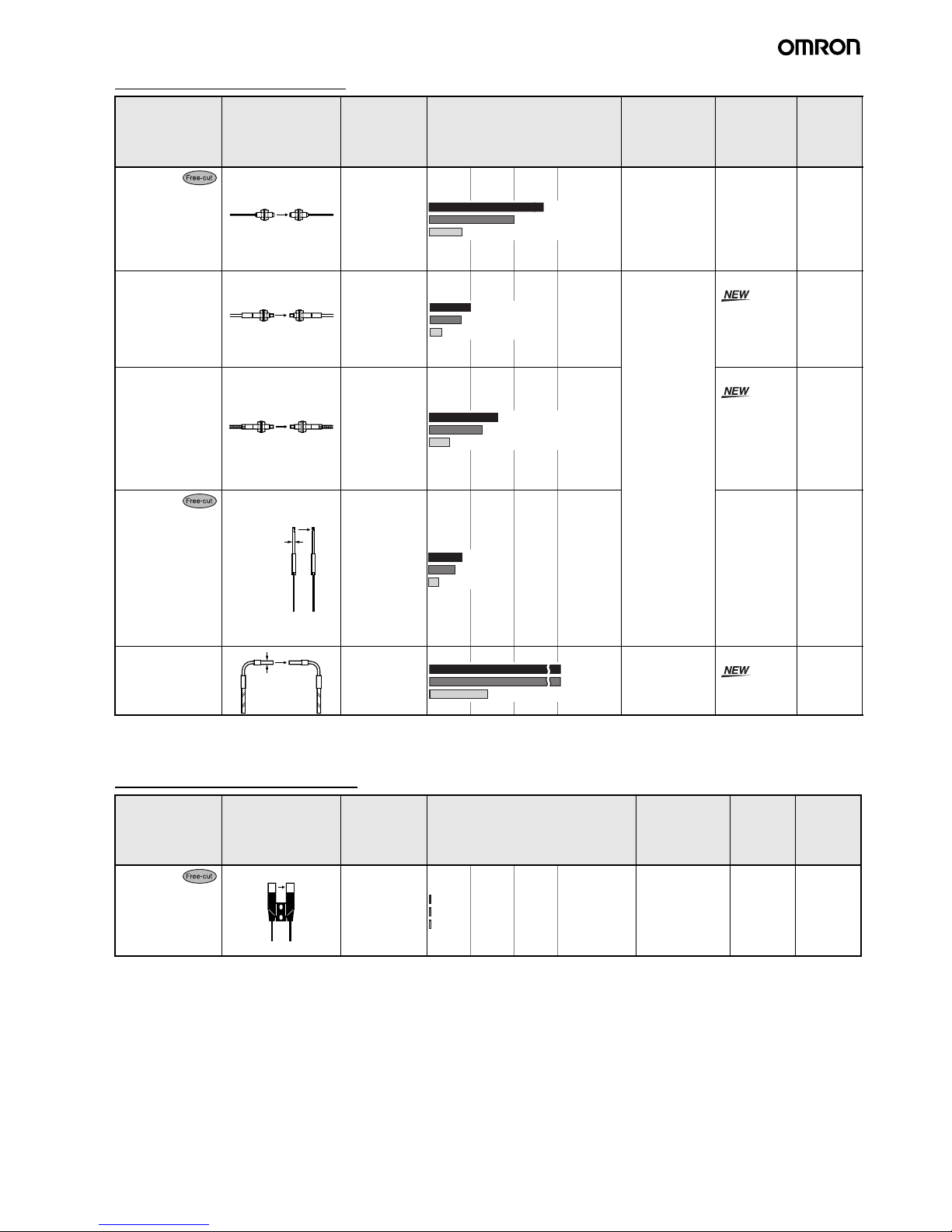
■ Through-beam Fiber Units
Note 1. Indicates models that allow free cutting. Models without this mark do not allow free cutting.
2. The size of standard sensing object is the same as the fiber core diameter (lens diameter for models with lens).
3. The values for the minimum sensing object are representative values that indicate values obtained in standard mode with the sensing dis-
tance and sensitivity set to optimum values.
Long-distance Fiber Units
Features Appearance Applicable
Amplifier Unit
Sensing distance (mm)
(Parentheses: With E39-F1 Lens
Unit)
Standard object
(min. sensing
object)
(Parentheses:
Opaque object)
Model Permissi-
ble bend-
ing radius
M4 E3X-MDA 1.4-mm dia.
(0.01-mm dia.)
E32-T11L 25 mm
3-mm dia. E3X-MDA E32-T12L
M3 E3X-MDA 0.9-mm dia.
(0.005-mm dia.)
E32-T21L 10 mm
2-mm dia.; small diameter
E3X-MDA E32-T22L
M14; with lens; ideal for explosionproof applications
E3X-MDA 10-mm dia. E32-T17L 25 mm
: High-resolution mode : Super-high-speed mode: Standard mode
M4 screw
350 (840)
1,100 (2,600)
*1
870 (2,000)
3-mm dia.
350
1,100
870
M3 screw
340
260
100
2-mm dia.
340
260
100
M14 screw
13,000
10,000
4,000
Conventional Fiber
Flexible Fiber
Conventional fiber uses just one core and
one cladding section. Bending the fiber
may break it or reduce the light intensity.
Flexible fiber contains multiple independent cores
all surrounded by cladding. The fiber can be bent
without breaking or reducing the light intensity.
Core
Cladding
Flexible fiber models are indicated by an
"R" at the end of the model number.
Flexible fiber contains multiple cores.
These cores are all surrounded by cladding,
giving a minimum bending radius of 1 mm.
The fiber can be bent at right angles without
affecting the light intensity. Handle it just like
any other cable.
A Wide Range of Flexible Fibers for Easy Installation without Loss of Light Intensity
6 E3X-MDA Super Dual Fiber Sensors
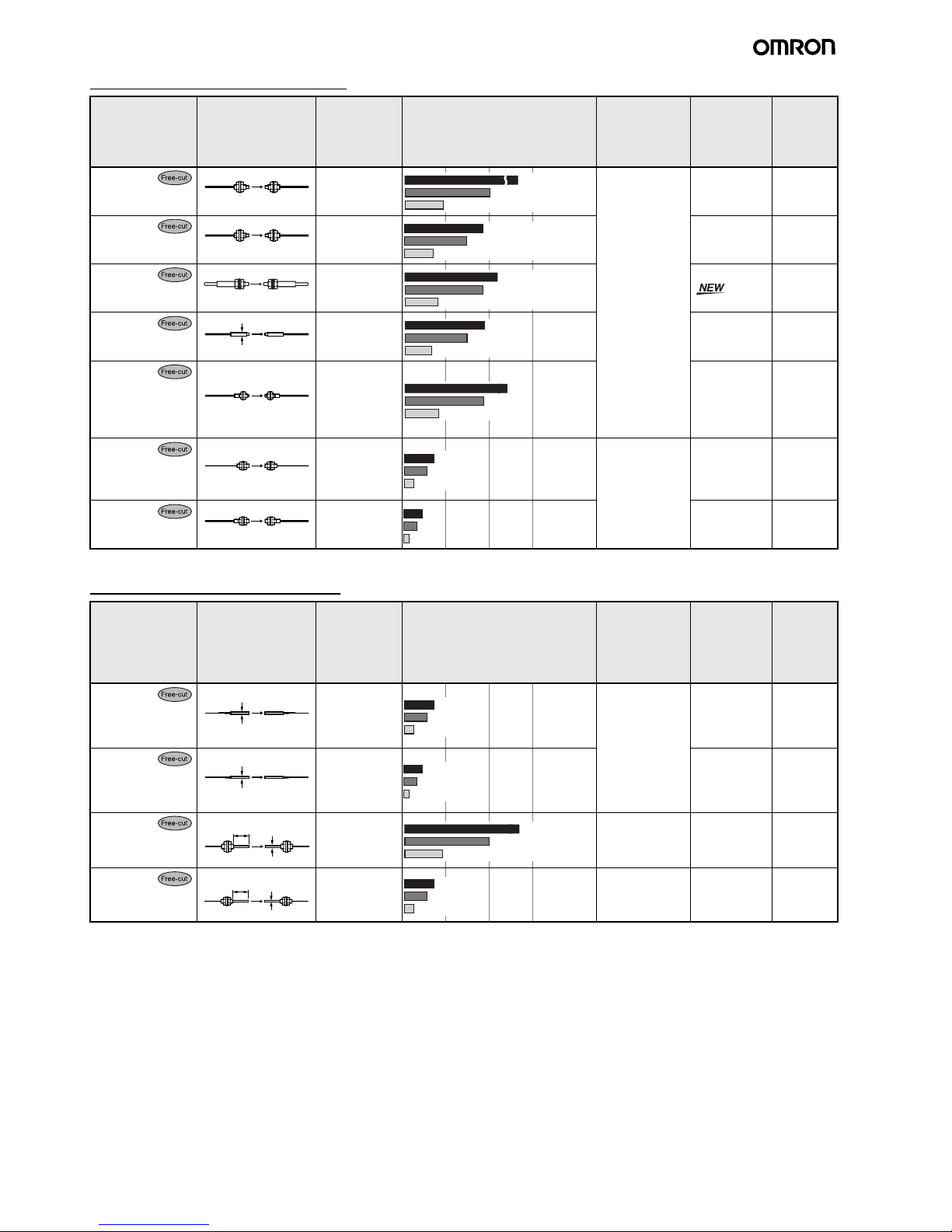
General-purpose Fiber Units
* The optical fiber is 2 m long on each side, so the sensing distance is 4,000 mm.
Fiber Units with Thin Heads
Features Appearance Applicable
Amplifier Unit
Sensing distance (mm)
(Parentheses: With E39-F1 Lens
Unit)
Standard object
(min. sensing
object)
(Parentheses:
Opaque object)
Model Permissi-
ble bend-
ing radius
M4 E3X-MDA 1.0-mm dia.
(0.005-mm dia.)
E32-TC200 25 mm
M4 E3X-MDA E32-T11R 1 mm
M4
Fiber sheath mate-
rial: fluororesin
E3X-MDA E32-T11U 4 mm
3-mm dia. E3X-MDA E32-T12R 1 mm
M3
Possible to mount
the E39-F5 Reflective Side-view Conversion Attachment
E3X-MDA E32-TC200A 25 mm
M3; for detecting
minute sensing objects
E3X-MDA 0.5-mm dia.
(0.005-mm dia.)
E32-TC200E 10 mm
M3 E3X-MDA E32-T21R 1 mm
M4 screw
500 (3,700)
200 (1,500)
650 (4,000)*
M4 screw
140 (970)
350 (2,400)
450 (3,100)
M4 screw
180 (930)
580 (3,000)*
450 (2,300)
3-mm dia.
140
350
450
M3 screw
180
450
580
M3 screw
50
130
170
M3 screw
75
100
30
Features Appearance Applicable
Amplifier Unit
Sensing distance (mm)
(Parentheses: With E39-F1 Lens
Unit)
Standard object
(min. sensing
object)
(Parentheses:
Opaque object)
Model Permissi-
ble bend-
ing radius
2-mm dia.; for detecting minute
sensing objects
E3X-MDA 0.5-mm dia.
(0.005-mm dia.)
E32-T22 10 mm
2-mm dia.; for detecting minute
sensing objects
E3X-MDA E32-T22R 1 mm
1.2-mm dia.; with
sleeve
E3X-MDA 1.0-mm dia.
(0.005-mm dia.)
E32-TC200B
E32-TC200B4
25 mm
0.9-mm dia.; with
sleeve
E3X-MDA 0.5-mm dia.
(0.005-mm dia.)
E32-TC200F
E32-TC200F4
10 mm
2-mm dia.
50
130
170
2-mm dia.
75
100
30
1.2-mm dia.
M4 screw
90 mm (40 mm)
( ): E32TC200B4
200
500
650
M3 screw
0.9-mm dia.
90 mm (40 mm)
( ): E32TC200F4
50
130
170
E3X-MDA Super Dual Fiber Sensors 7
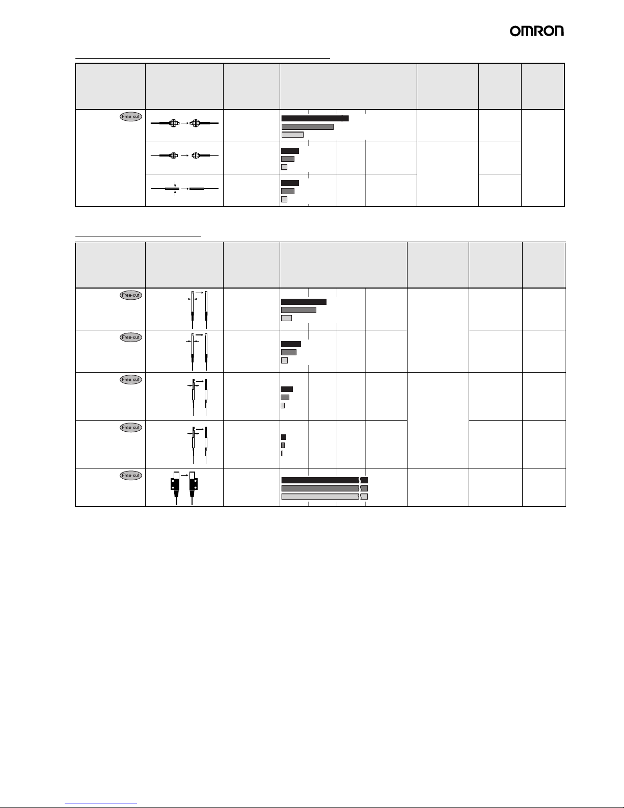
Flexible Fiber Units (Resists Breaking) (R4)
* The optical fiber is 2 m long on each side, so the sensing distance is 4,000 mm.
Side-view Fiber Units
Features Appearance Applicable
Amplifier Unit
Sensing distance (mm)
(Parentheses: With E39-F1 Lens
Unit)
Standard object
(min. sensing
object)
(Parentheses:
Opaque object)
Model Permissi-
ble bend-
ing radius
Ideal for mounting
on moving sections
(R4)
E3X-MDA 1.0-mm dia.
(0.005-mm dia.)
E32-T11 4 mm
E3X-MDA 0.5-mm dia.
(0.005-mm dia.)
E32-T21
E3X-MDA E32-T22B
M4 screw
180 (930)
580 (3,000)
450 (2,300)
M3 screw
45
110
150
1.5-mm dia.
45
110
150
Features Appearance Applicable
Amplifier Unit
Sensing distance (mm)
(Parentheses: With E39-F1 Lens
Unit)
Standard object
(min. sensing
object)
(Parentheses:
Opaque object)
Model Permissi-
ble bend-
ing radius
Long distance;
space-saving
E3X-MDA 1.0-mm dia.
(0.005-mm dia.)
E32-T14L 25 mm
Space-saving
E3X-MDA E32-T14LR 1 mm
Suitable for detecting minute sensing
objects; small diameter
E3X-MDA 0.5-mm dia.
(0.005-mm dia.)
E32-T24 10 mm
Suitable for detecting minute sensing
objects; small diameter
E3X-MDA E32-T24R 1 mm
Screw-mounting
type
E3X-MDA 4-mm dia.
(0.1-mm dia.)
E32-T14 25 mm
3-mm dia.
120
300
390
3-mm dia.
50
130
170
1-mm dia.
70
100
30
1-mm dia.
35
27
10
2,900
2,200
900
8 E3X-MDA Super Dual Fiber Sensors
Chemical-resistant Fiber Units
Features Appearance Applicable
Amplifier Unit
Sensing distance (mm)
(Parentheses: With E39-F1 Lens
Unit)
Standard object
(min. sensing
object)
(Parentheses:
Opaque object)
Model Permissi-
ble bend-
ing radius
Fluororesin-covered; round head
that resists water
drops
E3X-MDA 4-mm dia.
(0.1-mm dia.)
E32-T11F 4 mm
Fluororesin-covered; withstands
chemicals and
harsh environments
(operating ambient
temperature:
−30°C to 70°C)
E3X-MDA 4-mm dia.
(0.1-mm dia.)
E32-T12F 40 mm
Fluororesin-covered; withstands
chemicals and
harsh environments; side-view
(operating ambient
temperature:
−30°C to 70°C)
E3X-MDA 3-mm dia.
(0.1-mm dia.)
E32-T14F
Fluororesin; withstands chemicals
and harsh environments
(operating ambient
temperature:
−40°C to 200°C)
E3X-MDA 1.0-mm dia.
(0.005-mm dia.)
E32-T81F-S 10 mm
7.2-mm dia.
1,600
1,300
520
5-mm dia.
2,600
2,000
800
5-mm dia.
320
250
100
6-mm dia.
600
460
190
E3X-MDA Super Dual Fiber Sensors 9
Heat-resistant Fiber Units
*1: For continuous operation, use the products within a temperature range of −40°C to 130°C.
*2: Indicates the heat-resistant temperature at the fiber tip.
Fiber Unit with Slot Sensor
Features Appearance Applicable
Amplifier Unit
Sensing distance (mm)
(Parentheses: With E39-F1 Lens
Unit)
Standard object
(min. sensing
object)
(Parentheses:
Opaque object)
Model Permissi-
ble bend-
ing radius
Resists 150
°C
*1
; fiber sheath material: fluororesin
(operating ambient
temperature:
−40°C to 150°C)
E3X-MDA 1.5-mm dia.
(0.1-mm dia.)
E32-T51 35 mm
Resists 200
°C; flex-
ible (R10); fiber
sheath material:
fluororesin
(operating ambient
temperature:
−40°C to 200°C)
E3X-MDA 1.0-mm dia.
(0.005-mm dia.)
E32-T81R-S 10 mm
Resists 350
°C
*2
,
with spiral tube;
high mechanical
strength; fiber
sheath material:
stainless steel
(operating ambient
temperature:
−60°C to 350°C)
E3X-MDA E32-T61-S 25 mm
Side-view; resists
150
°C
*1
; suitable
for detecting minute
sensing objects; fiber sheath material: fluororesin
(operating ambient
temperature:
–40
°C to 150°C)
E3X-MDA E32-T54 35 mm
Resists 200
°C
*2
; Lshaped; fiber
sheath material:
stainless steel
E3X-MDA 1.7-mm dia.
(0.1-mm dia.)
E32-T84S-S 25 mm
M4 screw
650
500
200
M4 screw
230 (1,700)
180 (1,300)
70 (520)
M4 screw
390 (3,000)
300 (2,200)
120 (900)
2-mm dia.
190
150
60
3-mm dia.
1,100
870
350
Features Appearance Applicable
Amplifier Unit
Sensing distance (mm)
(Parentheses: With E39-F1 Lens
Unit)
Standard object
(min. sensing
object)
(Parentheses:
Opaque object)
Model Permissi-
ble bend-
ing radius
Suitable for film
sheet detection; no
optical axis adjustment required;
easy to mount
E3X-MDA 4-mm dia.
(0.1-mm dia.)
E32-G14 25 mm
10
10
10

10 E3X-MDA Super Dual Fiber Sensors
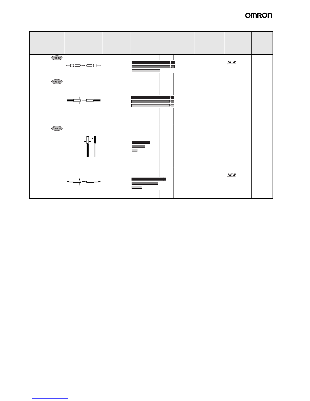
Fiber Units with a Narrow Vision Field
Area-sensing Fiber Units
*1: These figures are for a sensing distance of 300 mm. (Figures for the diameter of sensing objects are in the still state.)
*2: These figures are ones for which detection is possible in each sensing area at a digital incident level of 1,000.
(Figures for the diameter of sensing objects are in the still state.)
Features Appearance Applicable
Amplifier Unit
Sensing distance (mm)
(Parentheses: With E39-F1 Lens
Unit)
Standard object
(min. sensing
object)
(Parentheses:
Opaque object)
Model Permissi-
ble bend-
ing radius
Suitable for detecting wafers
E3X-MDA 1.7-mm dia.
(0.1-mm dia.)
E32-T22S 25 mm
Side-view; suitable
for detecting wafers
E3X-MDA 2-mm dia.
(0.1-mm dia.)
E32-T24S 10 mm
3-mm dia.
1,600
1,250
500
3.5 × 3-mm dia.
1,100
870
350
Features Appearance Applicable
Amplifier Unit
Sensing distance (mm)
(Parentheses: With E39-F1 Lens
Unit)
Standard object
(min. sensing
object)
(Parentheses:
Opaque object)
Model Permissi-
ble bend-
ing radius
Multi-point detection (4-head)
E3X-MDA 2-mm dia.
(0.1-mm dia.)
E32-M21 25 mm
Detects in a 30-mm
area
E3X-MDA (0.3-mm dia.)
*1
E32-T16W 10 mm
E3X-MDA E32-T16WR 1 mm
Side-view; suitable
for applications with
limited spatial
depth
E3X-MDA (0.2-mm dia.)
*1
E32-T16J 10 mm
E3X-MDA E32-T16JR 1 mm
Suitable for detecting over a 10-mm
area; long distance
E3X-MDA (0.6-mm dia.)
*2
E32-T16 25 mm
Stable for detecting
minute sensing objects in a wide area
E3X-MDA (0.2-mm dia.)
*1
E32-T16P 10 mm
E3X-MDA E32-T16PR 1 mm
M3 screw
470
360
140
30 mm
1,400
1,100
450
30 mm
1,100
860
340
11 mm
800
650
260
11 mm
600
480
190
10 mm
2,400
1,800
740
11 mm
970
750
300
11 mm
730
560
220
 Loading...