

Omron E3X-DA-N DATASHEET
Digital Fiber Amplifier
E3X-DA-N
Truly ultimate fiber amplifier
in pursuit of "user friendliness"
and "high performance"
UL991*
* UL-listed including UL991 tests/evaluations Applicable standard: UL3121-1 Standards for additional tests/evaluations
for applications: UL991, SEMI S2-0200
Features
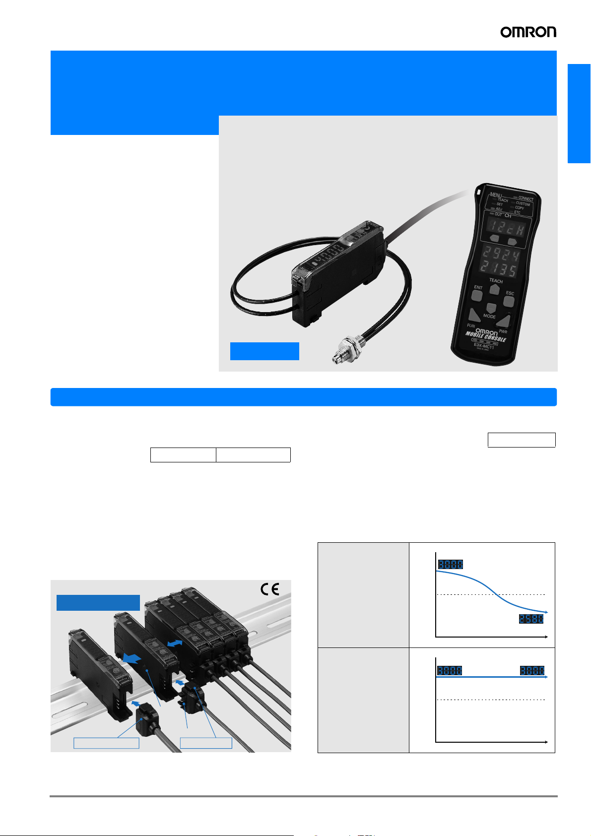
E3X-DA-N
Reducing power line wiring meaning
space is saved. New design for easier
maintenance.
The connector type that uses the wire-saving connector supplies power to the single-conductor slave connectors via the
three-conductor master connector. Hence, the following three
has been made possible.
1. Wiring is much simpler.
2. Relay connectors are not required meaning that space is used
more efficiently and costs are reduced.
3. Simple inventory control because of no differentiation between
master and slave in the amplifier section.
New Connector Design
Up to 16 Amplifiers
can be connected together.
Master Connector
Industry First Patent pending
Optical
communications
Power supply pin
Slave Connector
Super digital display by use of the Auto
Power Control (APC) circuit
The incident level of LEDs used in sensors is prone to deteriorate
with time and as a result, detection becomes unstable.
Using the APC (auto power control) circuit for the first time as the
fiber sensor, the E3X-DA-N series has no digital value variations,
realizing severe detection.
This makes the E3X-DA-N ideal for applications where a high degree of sensitivity is required, such as detecting crystal glass.
Incident level
3000
Conventional
Digital Fiber
Amplifiers
E3X-DA-N Series
Threshold
Detection becomes unstable
Time
Incident level
3000
Threshold
Time
Industry First
Stable detection
A-419E3X-DA-N
Power consumption reduced by 70%.
1800mW
600mW
Power consumption has been
reduced up to about 70%
from 1800 mW to 600 mW. (If
the digital display is off)
The digital display can be changed to fullOFF or Dark-ON during RUN.
Power consumption can be reduced by setting the display to FullOFF/Dark-ON in applications where the digital display is rarely
looked at during RUN.
(Can be set at the Mobile Console only)
Eco mode
Previous models E3X-DA-N
(Digital display not lit)
This ECO label is indicated on
products that meet the environmental
standards established by OMRON.
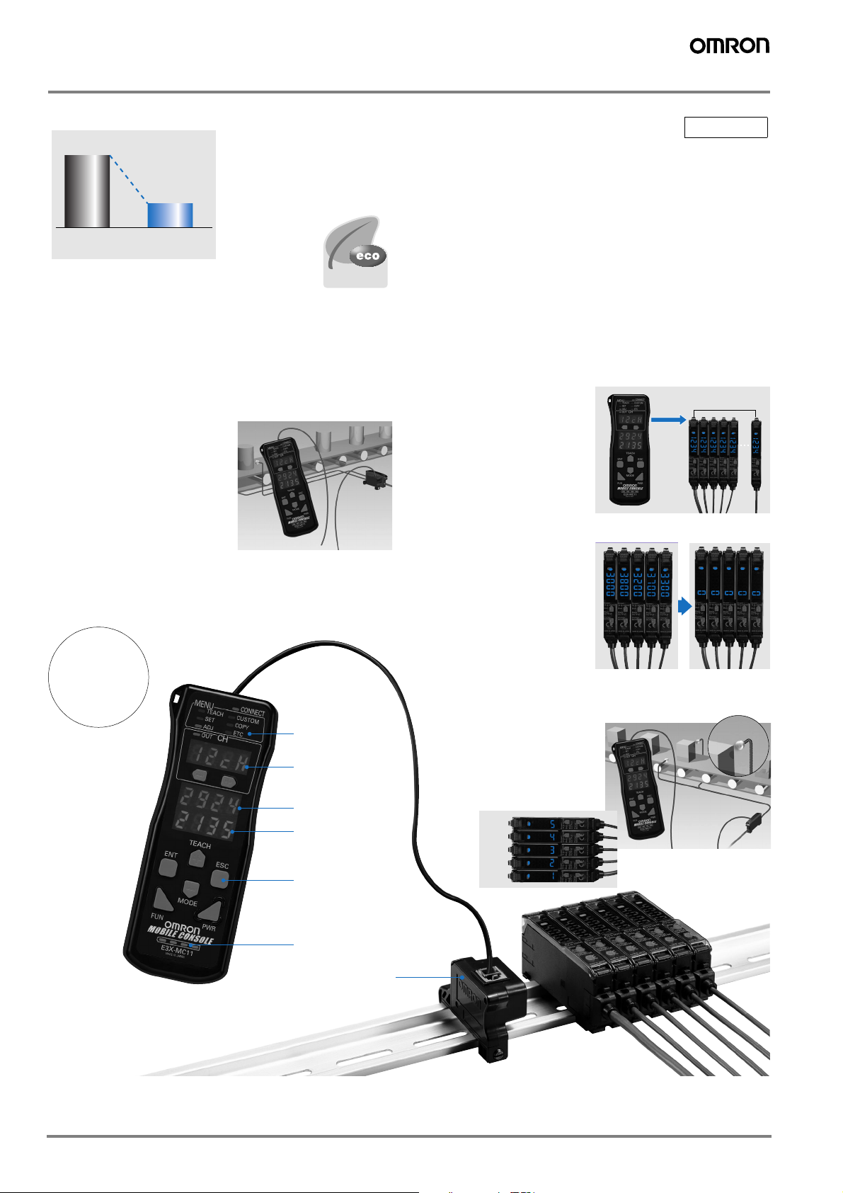
Beeper-sized, new-generation Mobile Console
unleashing the power of the ultimate fiber amplifier
Remote setting/adjustment function
Setting/teaching/fine adjustment can
be made at the fiber front-end.
The Mobile Console has enabled
setting and teaching at the fiber
front-end, which could only be
made at the amplifier. You can
perform major adjustments while
looking at the work position, etc.
Incident level and threshold can be displayed simultaneously.
New
Simultaneous turning possible using group teaching.
While teaching had to be
performed for each Amplifier
separately, it can now be
performed for several Amplifiers at once using the Mobile Console.
Differences in incident light avoided by group zero-reset.
The incident levels of several amplifiers can be batchreset to zero by the group
zero-reset. This feature is
useful for reducing differences between the amplifiers.
Concept
Patent
pending
Function indicator
Channel settings
Incident level monitor
Threshold display
Operation keys
Sensor head flashing during Amplifier operation
Alternatively, the amplifier channel can be displayed.
If the amplifier being operated is away from the sensor
head, the sensor head can be
flashed or the amplifier channel can be displayed.
Group teaching
5ch
4ch
3ch
2ch
1ch
Battery monitor
Head
Optical
communications
A-420 Advanced Photoelectric Sensors
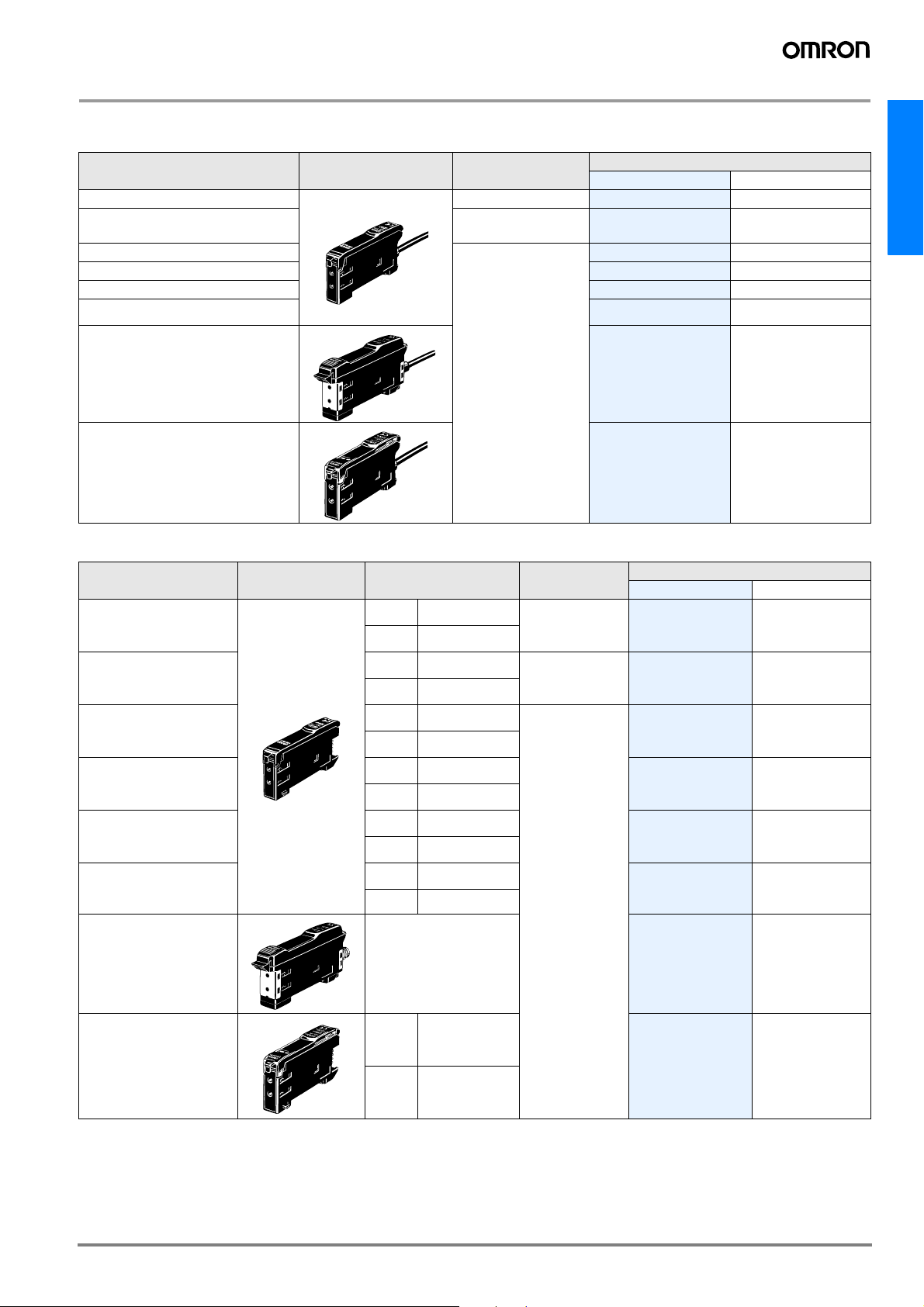
Ordering Information
Amplifier units
Prewired
Item Shape Control output
Standard models ON/OFF output
Monitor-output models
Mark-detecting models (Blue LED)
Mark-detecting models (Green LED)
Infrared models
Differential output type
·ON/OFF output
·Monitor output
Model
NPN output PNP output
E3X-DA11-N E3X-DA41-N
E3X-DA21-N E3X-DA51-N
E3X-DAB11-N E3X-DAB41-N
E3X-DAG11-N E3X-DAG41-N
E3X-DAH11-N E3X-DAH41-N
E3X-DA11D
---
E3X-DA-N
Water-resistant models
Twin-output models
Connector type
Item Shape
Standard models
Monitor-output models
Mark-detecting models
(Blue LED)
Mark-detecting models
(Green LED)
ON/OFF output
Applicable Connector
(order separately)
Master E3X-CN11
Slave E3X-CN12
Master E3X-CN21
Slave E3X-CN22
Master E3X-CN11
Slave E3X-CN12
Master E3X-CN11
Slave E3X-CN12
E3X-DA11V E3X-DA41V
E3X-DA11TW E3X-DA41TW
Control output
ON/OFF output
·ON/OFF output
·Monitor-output
Model
NPN output PNP output
E3X-DA6 E3X-DA8
E3X-DA7 E3X-DA9
E3X-DAB6 E3X-DAB8
E3X-DAG6 E3X-DAG8
Infrared models
Differential output type
Water-resistant models
(M8 Connector)
Twin-output models
Master E3X-CN11
Slave E3X-CN12
Master E3X-CN11
Slave E3X-CN12
XS3F-M421-40#-A
XS3F-M422-40#-A
Master E3X-CN21
Slave E3X-CN22
ON/OFF output
E3X-DAH6 E3X-DAH8
E3X-DA6D
E3X-DA14V E3X-DA44V
E3X-DA6TW E3X-DA8TW
---
A-421E3X-DA-N
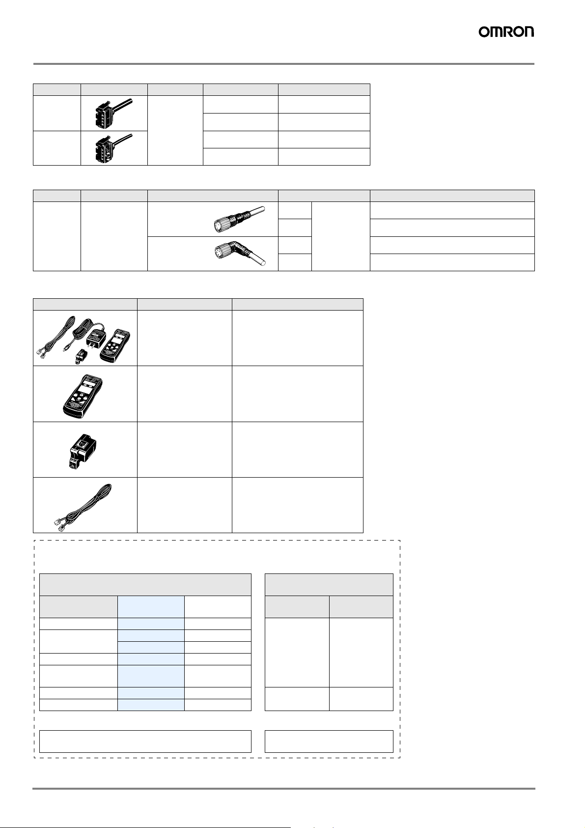
Amplifier units Connectors (Order Separately) Note: Stickers for Connectors are included as accessories.
Item Shape Cable length No. of conductors Model
Master
connector
2 m
Slave connector
3E3X-CN11
4E3X-CN21
1E3X-CN12
2E3X-CN22
Sensor I/O Connectors (Order separately)
Size Cable type Shape Cable length Model
M8 Standard cable
Straight
connector
L-shaped
connector
2 m
5 m XS3F-M421-405-A
4 conductors
2 m XS3F-M422-402-A
5 m XS3F-M422-405-A
XS3F-M421-402-A
Mobile Console (Order Separately)
Shape Model Remarks
Mobile Console with head, cable,
(Set form)
E3X-MC11
and AC adapter provided as ac-
cessories. Power supply provid-
ed by chargeable battery
E3X-MC11-C1 Mobile Console
E3X-MC11-H1 Head
E39-Z12-1 Cable (1.5 m)
In general, amplifier units and connectors are sold separately.
Refer to the following tables for order placement.
amplifier units
Type
Standard models
Mark-detecting models
Infrared models
Differential
output
Monitor-output models
Twin-output models
NPN PNP
E3X-DA6 E3X-DA8
E3X-DAB6 E3X-DAB8
E3X-DAG6 E3X-DAG8
E3X-DAH6 E3X-DAH8
E3X-DA6D ---
E3X-DA7 E3X-DA9
E3X-DA6TW E3X-DA8TW
+
Applicable Connector
(order separately)
Master
connector
E3X-CN11 E3X-CN12
E3X-CN21 E3X-CN22
Slave
connector
When using 5 sets
amplifier units (5 Units)
1 Master Connector + 4 Slave
+
Connectors
A-422 Advanced Photoelectric Sensors
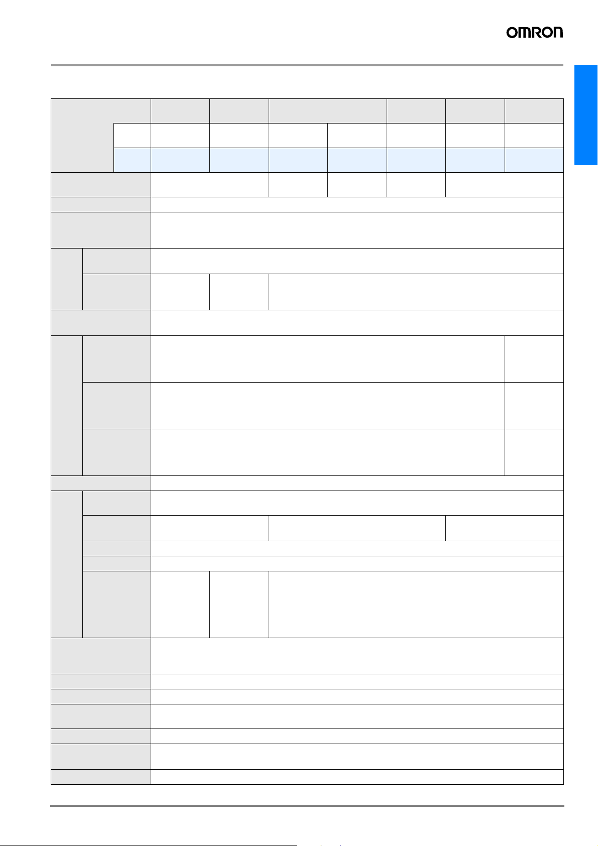
Rating/Performance
Amplifier units
Prewired
Type
Model
Item
Light source
(wave length)
Power supply voltage
Power consumption
Control
output
Protective circuits
Respons
e time
Sensitivity setting
Functions
Indicator lamp
Display timing
Display direction
Optical axis adjustment
function
Ambient lighting
Ambient temperature
Ambient humidity
ON/OFF output
Monitor output
Super-highspeed mode:
Standard mode:
Super-long-distance mode:
Timer functions
Automatic power control (APC)
Zero reset
Initial reset
Monitor focus
NPN
output
PNP
output
Red LED (660 nm)
12 to 24 VDC ±10%, ripple (p-p) : 10% max.
Normal: Power consumption 960 mW max. (power consumption 40 mA max. at supply voltage 24 V) Eco
mode: Power consumption 720 mW max. (power consumption 30 mA max. at supply voltage 24 V) Digital
display OFF: Power consumption 600 mW max. (power consumption 25 mA max. at supply voltage 24 V)
Load current 50 mA (residual voltage NPN/PNP: 1 V max. each) Open collector output type (depends on the
NPN/PNP output format) Light-ON/Dark-ON, switch selectable
Reverse polarity protection, output short-circuit protection, mutual interference prevention (possible for up to
10 amplifiers)
0.25 ms for operation and reset respectively
Operation/reset: 1 ms each
4 ms for operation and reset respectively
Teaching or manual method
OFF delay 0 to 200 ms (1 to 20: 1 ms increments, 20 to 200 ms: 5 ms increments), when the Mobile Control
is used, select either OFF delay, ON delay or one shot.
Fiber-optic current digital con-
trol
Yes (negative indication possible)
Yes (setting conditions initialized)
Operation indicator (orange), 7-segment digital incident level display (red), 7-segment digital incident level
percent display (red), incident level & threshold value double-bar display (green, red), 7-segment digital
threshold value display (red)
Normal/peak hold/bottom hold selectable
Normal/reverse selectable
Yes (hyper flashing emission function)
Incandescent lamp: 10,000 lux max. Sunlight 20,000 lux max.
Operating: Groups of 1 to 3 amplifiers: -25 to +55°C, Groups of 4 to 11 amplifiers: -25 to +50°C, Groups of
12 to 16 amplifiers: -25 to +45°C Storage: -30 to +70°C (with no icing and condensation)
Operating/Storage: 35% to 85% RH (with no condensation)
Standard
models
E3X-DA11-N E3X-DA21-N E3X-DAB11-N
E3X-DA41-N E3X-DA51-N E3X-DAB41-N
---
---
Monitor-output models
1 to 5 VDC,
load 10 k
min.
Upper and
lower limit values of output
range can be
set per digital
value of 100
Mark-detecting models
Blue LED
(470 nm)
E3X-DAG11-N
E3X-DAG41-N
Green LED
(525 nm)
---
Infrared
models
E3X-DAH11-N
E3X-DAH41-N
Infrared LED
(870 nm)
---
---
Water-resis-
tant models
E3X-DA11V
E3X-DA41V
Red LED (660 nm)
Fiber-optic current digital
control
Twin-output
models
E3X-DA11TW
E3X-DA41TW
0.5 ms for
operation
and reset
respectively
2 ms for
operation
and reset
respectively
7 ms for
operation
and reset
respectively
E3X-DA-N
A-423E3X-DA-N
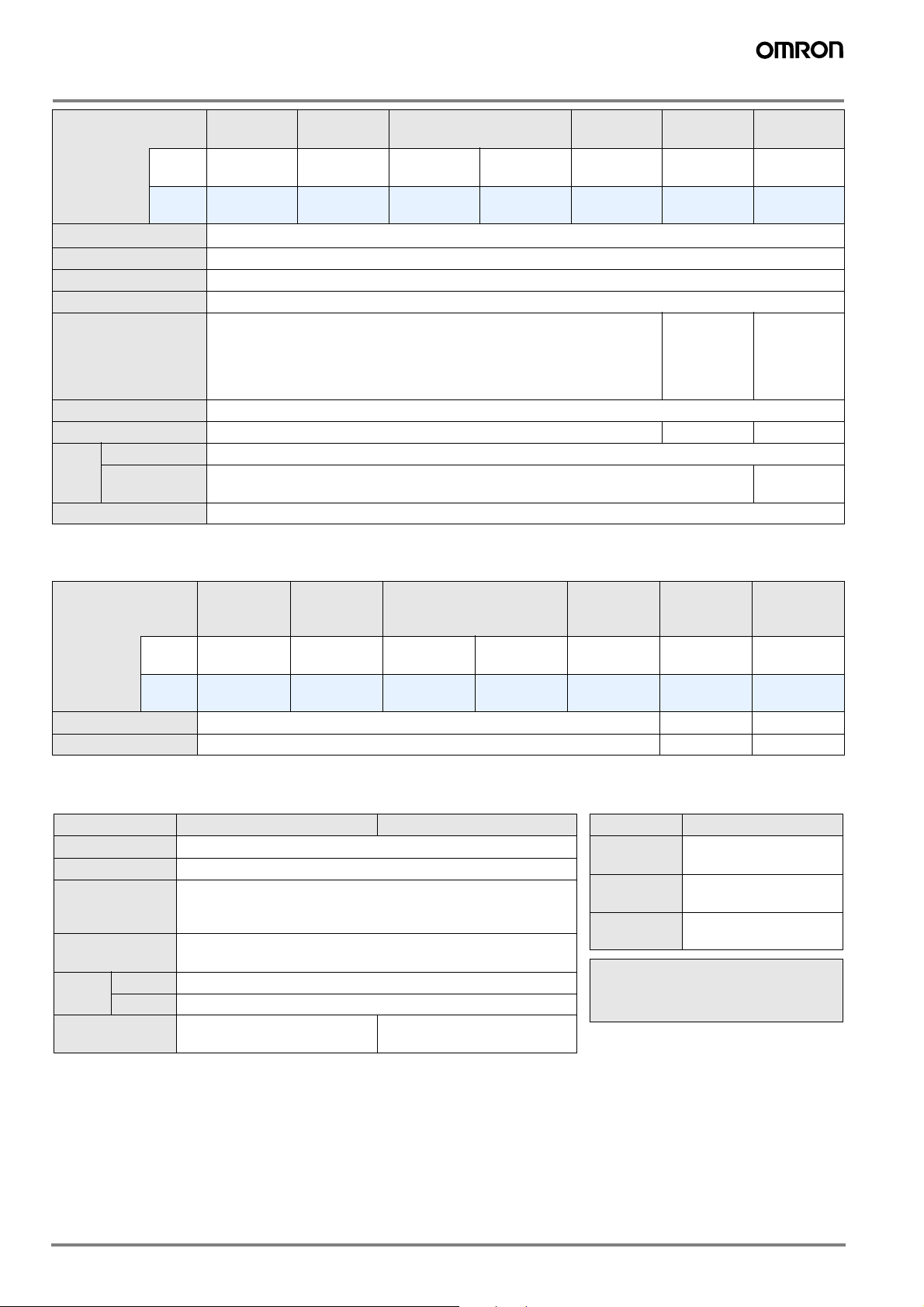
Type
Model
Item
Insulation resistance
Dielectric strength 1,000 VAC at 50/60 Hz for 1 minute
Vibration resistance 10 to 55 Hz, 1.5 mm double amplitude for 2 hours each in X, Y, and Z directions
Shock resistance Destruction: 500 m/s2 for 3 times each in X, Y, and Z directions
Degree of protection IEC 60529 IP50 (with Protective Cover attached)
Connection method Prewired models (standard length: 2 m)
Weight (Packed state) Approx. 100 g Approx. 110 g Approx. 100 g
Material
Accessories Instruction manual
Case PBT (polybutylene terephthalate)
Cover Polycarbonate
NPN
output
PNP
output
Standard
models
E3X-DA11-N E3X-DA21-N E3X-DAB11-N
E3X-DA41-N E3X-DA51-N E3X-DAB41-N
20 M min. at 500 VDC
Monitor-output models
Mark-detecting models
E3X-DAG11-N
E3X-DAG41-N
Infrared
models
E3X-DAH11-N
E3X-DAH41-N
Water-resis-
tant models
E3X-DA11V
E3X-DA41V
lEC 60529
IP66 (with
protective
cover attached)
Twin-output
models
E3X-DA11TW
E3X-DA41TW
IEC 60529
IP50 (with
protective
cover
attached)
Polyethersulfone
Connector type
Specifications that differ from those of the prewired type
Type
Model
Item
Connection method Connector type M8 connector Connector
Weight (Packed state) Approx. 55 g 65 g Approx. 55 g
* For waterproof type only, voltage resistance is 500 VAC 50/60 Hz 1 min
NPN
output
PNP
output
Standard
models
E3X-DA6 E3X-DA7 E3X-DAB6 E3X-DAG6 E3X-DAH6
E3X-DA8 E3X-DA9 E3X-DAB8 E3X-DAG8 E3X-DAH8
Monitor-output models
Mark-detecting models
Infrared
models
Water-resis-
tant models
(See note.)
E3X-DA14V
E3X-DA44V
Twin-output models
E3X-DA6TW
E3X-DA8TW
Amplifier unit Connectors
Item Model E3X-CN11/21/22 E3X-CN12
Rated current 2.5 A
Rated voltage 50 V
20 m max. (20 mVDC max., 100 mA max.) [By connection with
Contact resistance
No. of insertions
Material
Weight
(Packed state)
Housing PBT (polybutylene terephthalate)
Contacts Phosphor bronze/gold-plated nickel
amplifier unit and connection with adjacent connector
(except conductor resistance of cable)]
50 times (By connection with amplifier unit and connection with adjacent connector)
Approx. 55 g Approx. 25 g
Mobile Console
Item Model E3X-MC11
Supply volt-
age
Connection
method
Weight
(packed state)
For details of the Mobile Console, refer
to the instruction manual attached to the
product.
Charged with AC adapter
Connected via adapter
Approx. 580 g (Console
only: 120 g)
A-424 Advanced Photoelectric Sensors
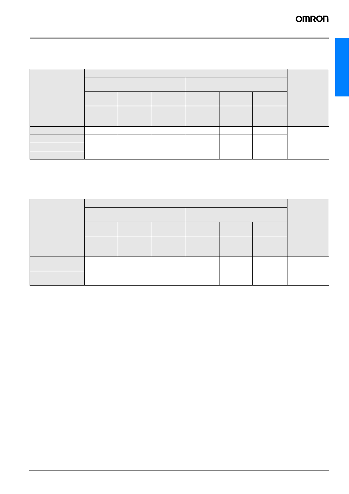
Digital Fiber Amplifier
* Differential output digital fiber amplifier (E3X-DA11D/E3X-DA6D)
Applicable fiber unit characteristic
(Through-beam model)
Sensing distance (mm) (Values in parentheses: When using the E39-F1 lens unit)
Sensitivity
switching
11 steps can be
Fiber type
set
Re-
sponse
time
1 2 3-11 1 2
270 or
570 s
E32-ET11R 240 (1680) 280 (1960) 370 (2590) 140(980) 180(1260) 240 (1680)
E32-ET21R 50 60 80 30 40 50
HIGH LOW
0.5 or 1 ms
1 to 200 ms or 2
to 400 ms
270 or
570 s
0.5 or 1 ms
3-11
1 to 200 ms or 2
to 400 ms
Standard object (mm) *1
Minimum sensing object
*2 (Opaque object) de-
fault
1 mm dia. (0.01
mm dia.)
E32-T16WR 580 690 910 350 450 580 (0.3 mm dia.)*3
E32-T16PR 380 450 600 230 290 380 (0.2 mm dia.)
*1. The sensing object is operating.
*2. Value applied when the response time is set to 3-11. The value can be detected if the temperature varies within the operating ambient temperature. (Value when
the sensing object is operating)
*3. The digital value is 1000 and the value can be detected in each detection area.
Refer to the E3X-DA-N for the note of the fiber unit.
(Reflective model)
Sensing distance (mm)*1
Sensitivity
switching
11 steps can be
Fiber type
set
Re-
sponse
time
1 2 3-11 1 2
270 or
570 s
E32-ED11R 80 90 120 45 60 80
E32-ED21R 13 15 20 7 10 13
*1. Sensing distance indicates values for white paper.
*2. The sensing object is operating.
*3. Value applied when the response time is set to 3-11. The value can be detected if the temperature varies within the operating ambient temperature. (Value when
the sensing object is operating)
Note: Refer to E3X-DA-N for the note of the fiber unit.
HIGH LOW
0.5 or 1 ms
1 to 200 ms or 2
to 400 ms
270 or
570 s
0.5 or 1 ms
3-11
1 to 200 ms or 2
to 400 ms
Standard object (mm) *2
Minimum sensing object
*3 (Opaque object) de-
fault
150 x 150 (0.01
mm dia.)
25 x 25 (0.01 mm
dia.)
E3X-DA-N
A-425E3X-DA-N
 Loading...