

Omron E3X-DAC-S DATASHEET
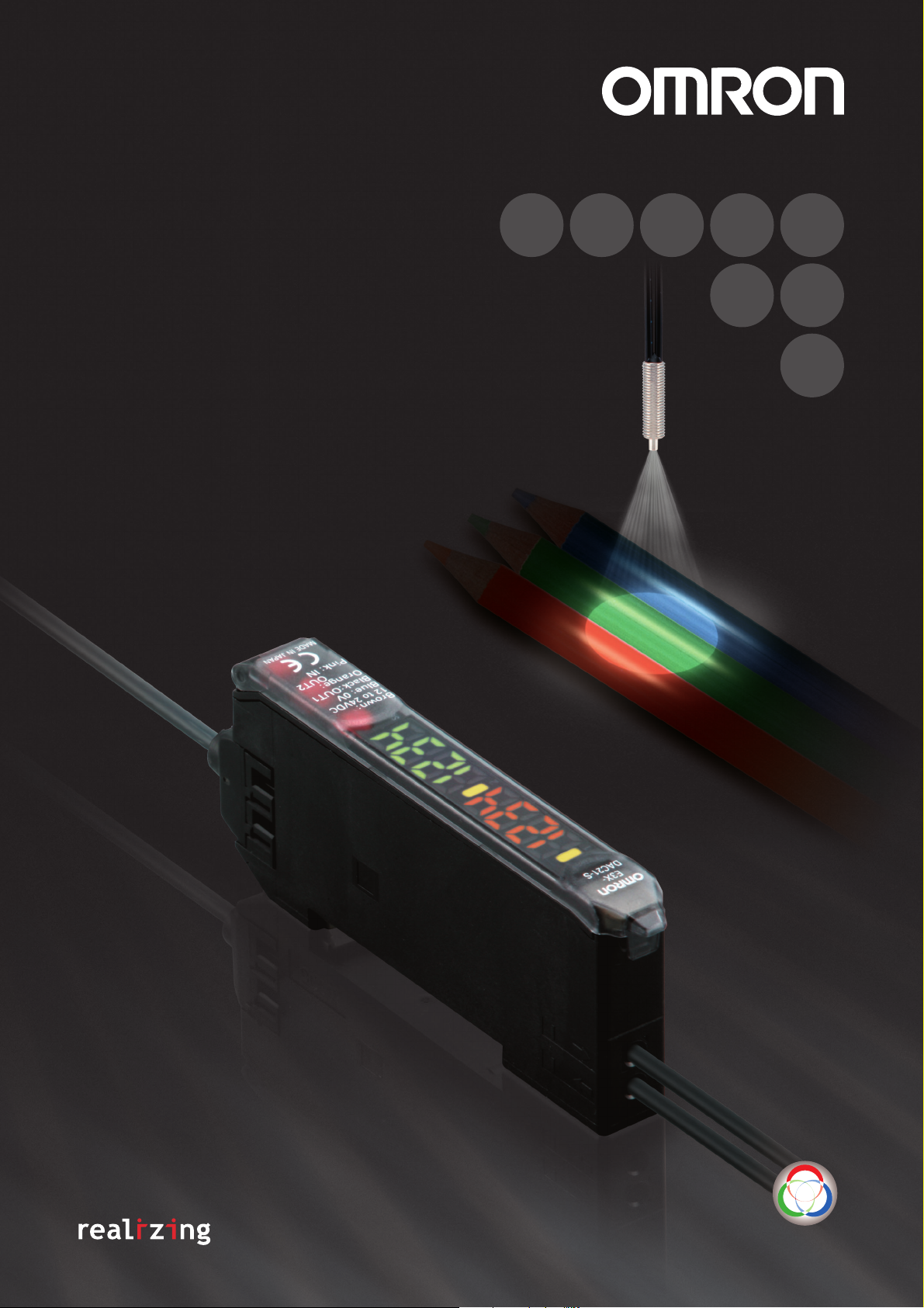
Color Sensing
Digital Fiber Sensor
E3X-DAC-S
Easy and Reliable
The Fiber Sensor That Sees in Color
Color Sensing
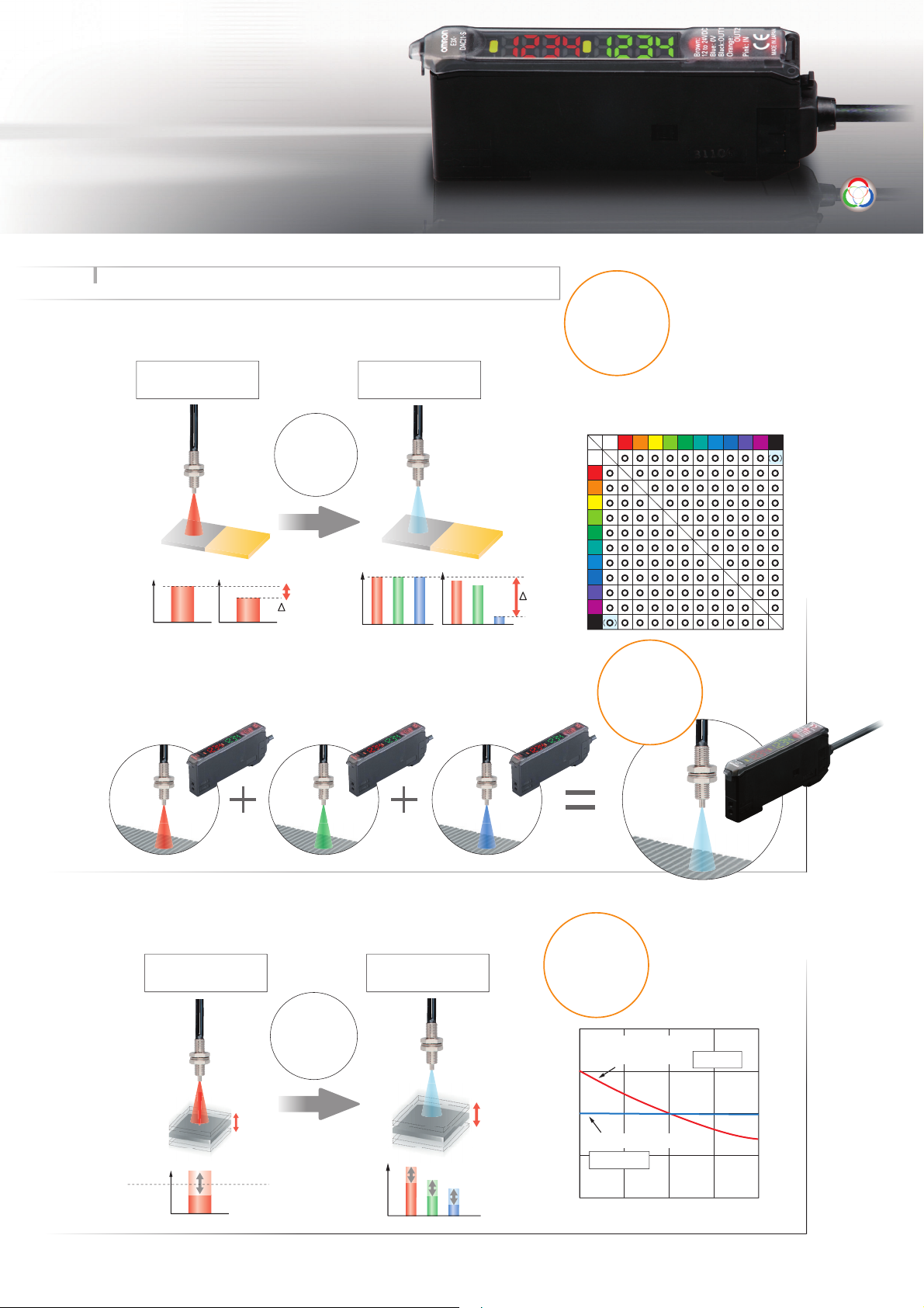
Color-sensing Engine
Easy and Reliable ... Featuring a Color-sensing Engine
The color-sensing engine uses three parameters, RGB, to process
incident light. It detects color information from the workpiece for precise
detection of color differences.
Incident light
intensity
Intensity Detection
(Conventional Type)
100
90
Unstable...
RGB ratio
10
Color Detection
(Color Sensing Type)
100
100
100
90
Color Sensing
Precise
Detection
Color VS. Detection Capability
hite
Yellow-red
Yellow
Yellow-green
Blue
Blue-violet
Violet
Red-violet
W
Red
White
Red
Yellow-red
Yellow
Yellow-green
Green
Blue-green
Blue
Blue-violet
Violet
80
90
10
Red-violet
Black
Green
Blue-green
Black
A high-power white LED and a multi-RGB processing system combine to cover all
RGB wavelengths, enabling easy and accurate detection of workpieces without
having to use a different light source to match each one.
Changes in the three parameters are processed as a ratio, so they are
not affected by light-intensity variations due to workpiece movement.
Resists
Incident light
intensity
Intensity Detection
(Conventional Type)
80 to 130
Misdetec-
tion...
RGB ratio
Color Detection
(Color Sensing Type)
8 : 5 : 3
Movement
100%
50%
0%
−50%
Digital value (%)
−100%
−20% −10% 10% 20%
No Need
to Select
Intensity
Detection
Color Detection
Not affected
0%
Distance change (%)
Affected
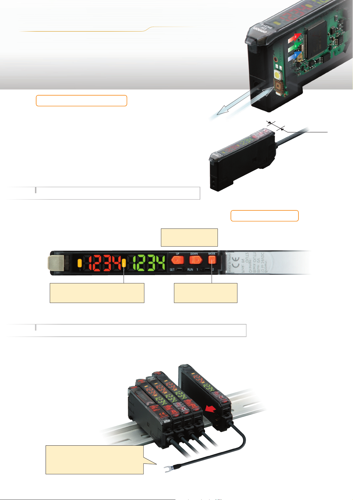
Amplif ier Unit
Thinnest in the Industry
A Slim, 10-mm-wide Amplifier Unit
Use of a white LED and a one-package RGB light-receiving
element has made it possible to unify the Amplifier Unit,
both in size and operation, with conventional models.
If detection should become unstable, the Amplifier Unit can
be separately replaced to immediately regain stability.
Easy and Reliable ... Ease of Use and Smart Functions
10 mm
In addition to ensuring easy use, we have added a number of smart
functions, such as remote control to simplify setup, and twin
sensing and output to simultaneously distinguish two registered
colors. (advanced models)
Easy to Understand
A double display for easy, precise setting.
Reliable
Setting guide function.
One push is all it takes.
Easy Setting
First in Its Class
This function guides the user to
ensure that the workpiece is in an
appropriate position for teaching.
(Indicates OVER, OK, or LOW.)
Easy and Reliable ... Simplified Wiring Connector Reduces Work Steps
OMRON's unique simplified wiring connectors provide
the power for each added Sensor. Up to 16 Units can
be mounted, including a combination of Digital Fiber
Sensors and other simplified wiring connector
products such as Digital Laser Sensors.
Power is supplied through the connector,
so only one output wire is
required. (For adding Sensors)
From left to right
Digital Fiber Sensors: E3X-NA
E3X-DA-S/MDA
E3X-DAC-S
Digital Laser Sensor: E3C-LDA
Proximity Sensor: E2C-EDA
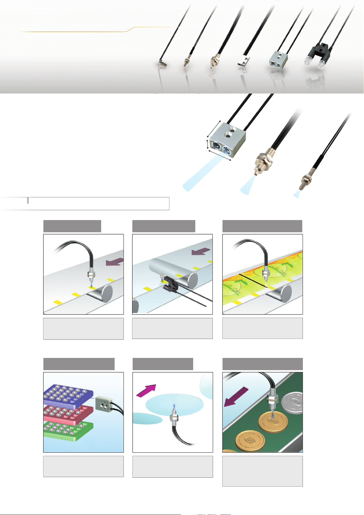
Application
Wide Range of
Fiber Heads Available
Select from a wide range of Fiber Heads to match
the workpiece and working space. This makes
installation possible even in small spaces.
Long-distance
Fiber Head
E32-A09
23 mm
9 mm
20 mm
Many Compact Heads
General-purpose
Fiber Head
E32-CC200
M6 screw
Compact
Fiber Head
E32-C31
M3 screw
Easy and Reliable Applications (Examples)
Detecting Marks
Because it distinguishes RGB
ratios, detection is highly resistant
to workpiece movement.
Distinguishing Trays Detecting Wafers
Distinguishing
Semi-transparent Objects
Through-beam Fiber Heads are
capable of detecting color differences
in semi-transparent objects.
Detection distance:
30 mm
Detection distance:
9 mm
Detection distance:
3 mm
Detecting Black Marks
In Black Mode, black seam tape and
other black marks can be detected
regardless of film color or patterns.
Detecting Products on
Conveyors
Twin sensing and remote control
functions simplify setup.
Workpieces that absorb a specific
wavelength can be detected with
a wide range of wavelengths.
If you teach the conveyor (i.e., the
background), you can detect
workpieces even if they have
different colors, shapes, or gloss.
E3X-DAC-S
Ordering Information
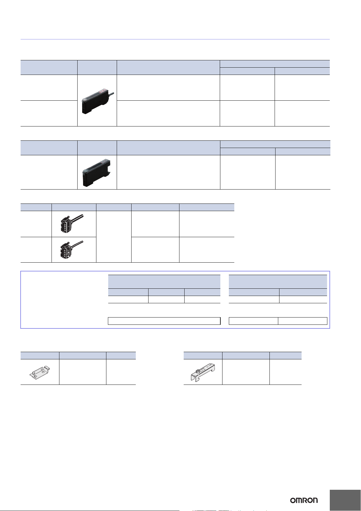
Amplifier Units
Amplifier Units with Cables
Item Appearance Functions
Standard models Timer, Response speed change E3X-DAC11-S 2M E3X-DAC41-S 2M
Standard models + Simultaneous determi-
Advanced models
Amplifier Units with Connectors (Amplifier Unit Connectors must be purchased separately.)
Item Appearance Functions
Standard models Timer, Response speed change E3X-DAC6-S E3X-DAC8-S
nation (2 colors)
AND/OR output, Remote setting
NPN output PNP output
E3X-DAC21-S 2M E3X-DAC51-S 2M
NPN output PNP output
Model
Model
Amplifier Unit Connectors (Order Separately) Note: Protector seals are provided as accessories.
Item Appearance Cable length No. of conductors Model
Master
Connector
2 m
Slave
Connector
Combining Amplifier Units and
Connectors
Amplifier Units and Connectors are sold separately. Refer to the following tables when
placing an order.
Standard models E3X-DAC6-S E3X-DAC8-S
When Using 5 Amplifier Units
Amplifier Units (5 Units) + 1 Master Connector 4 Slave Connectors
3 E3X-CN11
1 E3X-CN12
Amplifier Unit
Model NPN output PNP output Master Connector Slave Connector
+
E3X-CN11 E3X-CN12
Applicable Connector
(Order Separately)
Accessories (Order Separately)
Mounting Bracket End Plate
Appearance Model Quantity
E39-L143 1
Appearance Model Quantity
PFP-M 1
5
E3X-DAC-S
Ratings and Specifications
Amplifier Units
Type Standard models Advanced models
Item Model E3X-DAC@-S@ (@: 11/41/6/8) E3X-DAC@-S@ (@: 21/51)
Sensing distance Depends on the Fiber Unit. Refer to pages 8 to 10.
Sensing object
Light source (wavelength) White LED (420 to 700 nm)
Sensing method
Number of registered colors 1 2 (simultaneous determination)
Power supply voltage 12 to 24 VDC ±10%, ripple (p-p) 10% max.
Power consumption 960 mW max. (current consumption: 40 mA max. at power supply voltage of 24 VDC)
Control output
Remote control input
Protection circuits
Super-high-speed mode
Response
time
Sensitivity setting
(color registration, allowable range)
Functions
Display
Digital display 7-segment displays (Main display: Red, Sub-display: Green), display direction can be reversed.
Ambient illumination (Receiver side)
Ambient temperature range
(See note 6.)
Ambient humidity range Operating and storage: 35% to 85% (with no condensation)
Insulation resistance 20 MΩ min. (at 500 VDC)
Dielectric strength 1,000 VAC at 50/60 Hz for 1 minute
Vibration resistance Destruction: 10 to 50 Hz with a 1.5-mm double amplitude for 2 hrs each in X, Y and Z directions
Shock resistance Destruction: 500 m/s2, for 3 times each in X, Y and Z directions
Degree of protection IEC 60529 IP50 (with Protective Cover attached)
Connection method
Weight (packed state) Pre-wired model: Approx. 100 g, Amplifier unit connector model: Approx. 55 g
Materials
Accessories Instruction manual
(See note 4.)
High-speed mode
Standard mode
High-resolution mode
Operating mode
Timer function
Control outputs ---
Remote control ---
Display switch (See note 5.)
Initialization Initial reset (factory defaults) or user reset (saved settings)
Case Polybutylene terephthalate (PBT)
Cover Polycarbonate (PC)
Reflective models: Standard 11 color cards (See note 1.), Through-beam models: Opaque or translucent object
C Mode: RGB ratio determination (or I Mode: Light intensity determination for red, green, or blue,
Black Mode: Determination of total light intensity for red, green, and blue) (See note 2.)
NPN or PNP open collector
Load power supply voltage: 26.4 VDC max.
Load current: 50 mA max. (residual voltage: 2 V max.)
---
Reverse polarity for power supply connection, output short-circuit, Reversed output polarity protection
Operate or reset: 60 µs
Operate or reset: 300 µs
Operate or reset: 1 ms
Operate or reset: 4 ms
Teaching (one-point teaching or teaching with/without workpiece) or manual adjustment
ON for match (ON for same color as registered color) or ON for mismatch (ON for different color
from registered color)
Timer type: OFF delay, ON delay, or one-short
Timer time: 1 ms to 5 s (variable)
Seven patterns total: Match + Threshold, Margin + Threshold, Analog bar display, Peak + Bottom,
etc.
Operation indicator (orange)/
I mode display indicator (orange)
Incandescent lamp: 3,000 lux
Sunlight: 10,000 lux
Operating: −25°C to 55°C
Storage: −30°C to 70°C (with no icing or condensation)
Pre-wired or Amplifier Unit Connector (Units connected: 16 max.)
No-voltage input (contact/transistor)
(See note 3.)
Operate or reset: 120 µs
Operate or reset: 600 µs
Operate or reset: 2 ms
Operate or reset: 8 ms
Output for each channel, AND output, and OR
output
One-point teaching, teaching with/without workpiece, zero reset, and light emission OFF
Channel 1 and channel 2 operation indicators
(orange)
Pre-wired
6
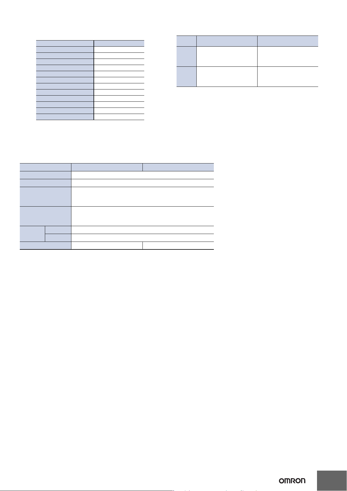
Note:1. Sensing Object: Standard Color Card (230 Colors) from Japan Color
Enterprise Co., Ltd.)
Color (11 standard colors) Munsell color notation
White N9.5
Red 4R 4.5/12.0
Yellow/red 4YR 6.0/11.5
Yellow 5Y 8.5/11.0
Yellow/green 3GY 6.5/10.0
Green 3G 6.5/9.0
Blue/green 5BG 4.5/10.0
Blue 3PB 5.0/10.0
Blue/purple 9PB 5.0/10.0
Purple 7P 5.0/10.0
Red/purple 6RP 4.5/12.5
Black (N2.0)
2. When teaching with/without a workpiece, the best sensing method will
be automatically selected (RGB ratio (C Mode) or light intensity determination (I Mode)). If color differences are not strong enough and RGB
ratios would result in unstable detection, then light intensity determination (I Mode) will be selected.
The detection mode can also be set to C, I, or Black Mode.
NPN
PNP
Amplifier Unit Connectors
Item Model E3X-CN11 E3X-CN12
Rated current 2.5 A
Rated voltage 50 V
20 mΩ max. (20 mVDC max., 100 mA max.)
Contact resistance
No. of insertions
Materials
Housing Polybutylene terephthalate (PBT)
Contacts Phosphor bronze/gold-plated nickel
Weight (packed state) Approx. 55 g Approx. 25 g
(The figure is for connection to the Amplifier Unit and the adjacent
Connector. It does not include the conductor resistance of the cable.)
Destruction: 50 times
(The figure for the number of insertions is for connection to the Amplifier Unit and the adjacent Connector.)
E3X-DAC-S
3. Input Specifications
Contact input
(relay or switch)
ON: Shorted to 0 V (sourcing
current: 1 mA max.).
OFF: Open or shorted to Vcc.
ON: Shorted to Vcc (sinking
current: 3 mA max.).
OFF: Open or shorted to 0 V.
4. Mutual interference prevention cannot be used in super-high-speed
mode, and light intensity determination (I Mode) must be used.
5. With light intensity determination (I Mode), the correlation is not displayed, but rather the light intensity is displayed.
6. The allowable ambient operating temperature changes according to the
number of Units that are linked.
2 Units: −25 to 55°C, 3 to 10 Units: −25 to 50°C, and 11 to 16 Units:
−25 to 45°C
Non-contact input
(transistor)
ON: 1.5 V max. (sourcing cur-
rent: 1 mA max.)
OFF: Vcc - 1.5 V to Vcc (leakage
current: 0.1 mA max.)
ON: Vcc - 1.5 V to Vcc (sinking
current: 3 mA max.)
OFF: 1.5 V max. (leakage cur-
rent: 0.1 mA max.)
7
E3X-DAC-S
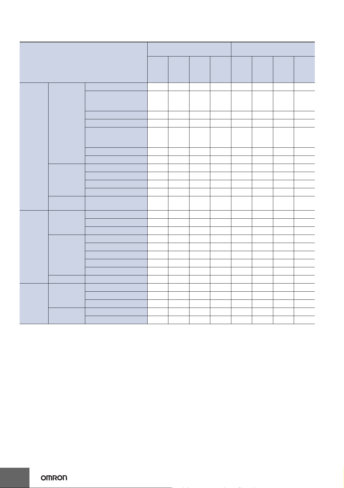
Sensing Distance
Reflective Models (Unit: mm)
Standard color card (11 colors)
(mutual determination)
High-
resolu-
tion
mode
20 to 38 24 to 36 26 to 32
Stan-
dard
mode
High-
speed
mode
Super-
high-
speed
mode
---
Type
Standard
models
Specialbeam
models
Environment
resistive
models
Sensing object White paper
High-
resolu-
tion
mode
E32-DC200 70 54 46 18 14 10 8.5 6
E32-D11R/E32-D12R/
E32-D15XR/E32-D11N/
E32-DC200BR (B4R)
Generalpurpose
Breakresistant
Fluorine
coating
Longdistance,
high power
Coaxial
Area sensing E32-D36P1 35 26 22 9 7.5 5 4.5 3
Heat-resistant
Chemical
resistant
E32-D14LR 11 8.5 7 2.5 2.4 1.7 1.4 1
E32-D15YR/E32-D15ZR 10 7.5 6.5 2.5 2.1 1.5 1.3 0.9
E32-D211/E32-DC200E/
E32-D22/E32-D25X/
E32-DC200F (F4)
E32-D24 8.8 6.7 5.8 2.1 1.8 1.3 1.1 0.7
E32-D25Y/E32-D25Z 5.8 4.5 3.8 1.4 1.2 0.9 0.7 0.5
E32-D11/E32-D15XB 42 32 26 11 8.5 6 5 3.5
E32-D21B/E32-D221B 19 15 13 4.5 4.1 3 2.4 1.5
E32-D21/E32-D22B 8.8 6.7 5.8 2.1 1.8 1.3 1.1 0.7
E32-D25XB 14 10 9 3 3 2.1 1.7 1.1
E32-D11U 42 32 26 11 8.5 6 5 3.5
E32-A09
E32-D11L 90 70 60 22 19 13 11 7.5
E32-D21L/E32-D22L 35 26 22 8 7 5 4 2.5
E32-CC200 60 45 35 16 12 9 7 4
E32-CC200R/E32-C11N 35 26 22 9 7.5 5 4.5 3
E32-D32L 35 26 22 9 7.5 5 4.5 3
E32-C31/E32-D32 17 13 11 4.5 3.7 2.7 2.2 1.5
E32-C31N 7.7 6 4.8 2.1 1.6 1.2 0.9 0.7
E32-D51 55 42 36 14 11 8.5 7 4.5
E32-D81R-S/E32-D61-S 20 15 13 5 4 3 2.5 1.5
E32-D73-S 13 10 8.5 3.5 2.8 2 1.7 1.2
E32-D12F 22 17 15 6 4.9 3.5 2.9 2
E32-D14F 97622.11.41.20.6
20 to 38 24 to 36 26 to 32
Stan-
dard
mode
42 32 26 11 8.5 6 5 3.5
20 16 14 5 4.5 3 2.5 1.5
High-
speed
mode
Super-
highspeed
mode
---
8
 Loading...