

Omron E3F3-T11, E3F3-D11, E3F3-D12, E3F3-T16, E3F3-R16 Datasheet
...
E3F3 Photoelectric Sensor 1
Photoelectric Sensor
E3F3
Threaded Cylindrical Photoelectric Sensor with Built-in Amplifier for Use as an Optical
Proximity Sensor
High Noise-immunity with
Photo-IC Technology
• Up-to-date photo-IC to increase noise immunity.
• M18 DIN-sized cylindrical housing, ABS resin case.
• Long sensing dist ance (30 cm) w ith sens itivity a djustor for diffuse type.
• Short-circuit and reverse connection protection.
<READ AND UNDERSTAND THIS CATALOG>
Please read and understand this catalog before
purchasing the products. Please consult your
OMRON representative if you have any questions or
comments.
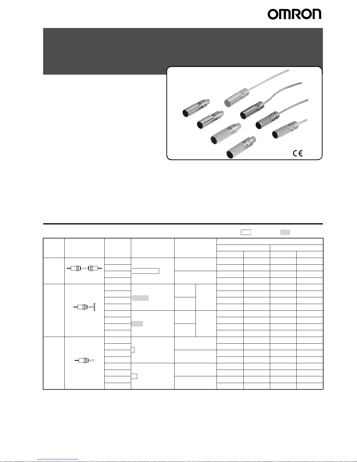
Ordering Information
Infrared light Red light
Sensing
method
Appearance Connec-
tion meth-
od
Sensing distance Operating modes Model
Plastic housing Metal housing
NPN output PNP output NPN output PNP output
Throughbeam
Pre-wired Light-ON E3F3-T11 E3F3-T31 E3F3-T11M E3F3-T31M
M12 CN E3F3-T16 E3F3-T36 E3F3-T16M E3F3-T36M
Pre-wired Dark-ON E3F3-T61 E3F3-T81 E3F3-T61M E3F3-T81M
M12 CN E3F3-T66 E3F3-T86 E3F3-T66M E3F3-T86M
Retroreflective
Pre-wired Light-ON Non-po-
larized
E3F3-R11 E3F3-R31 E3F3-R11M E3F3-R31M
M12 CN E3F3-R16 E3F3-R36 E3F3-R16M E3F3-R36M
Pre-wired Dark-ON E3F3-R61 E3F3-R81 E3F3-R61M E3F3-R81M
M12 CN E3F3-R66 E3F3-R86 E3F3-R66M E3F3-R86M
Pre-wired Light-ON Polarized E3F3-R12 E3F3-R32 E3F3-R12M E3F3-R32M
M12 CN E3F3-R17 E3F3-R37 E3F3-R17M E3F3-R37M
Pre-wired Dark-ON E3F3-R62 E3F3-R82 E3F3-R62M E3F3-R82M
M12 CN E3F3-R67 E3F3-R87 E3F3-R67M E3F3-R87M
Diffuse
reflective
Pre-wired Light-ON E3F3-D11 E3F3-D31 E3F3-D11M E3F3-D31M
M12 CN E3F3-D16 E3F3-D36 E3F3-D16M E3F3-D36M
Pre-wired Dark-ON E3F3-D61 E3F3-D81 E3F3-D61M E3F3-D81M
M12 CN E3F3-D66 E3F3-D86 E3F3-D66M E3F3-D86M
Pre-wired Light-ON E3F3-D12 E3F3-D32 E3F3-D12M E3F3-D32M
M12 CN E3F3-D17 E3F3-D37 E3F3-D17M E3F3-D37M
Pre-wired Dark-ON E3F3-D62 E3F3-D82 E3F3-D62M E3F3-D82M
M12 CN E3F3-D67 E3F3-D87 E3F3-D67M E3F3-D87M
5 m
3
m
2 m
100 mm
300 mm
2 E3F3 Photoelectric Sensor
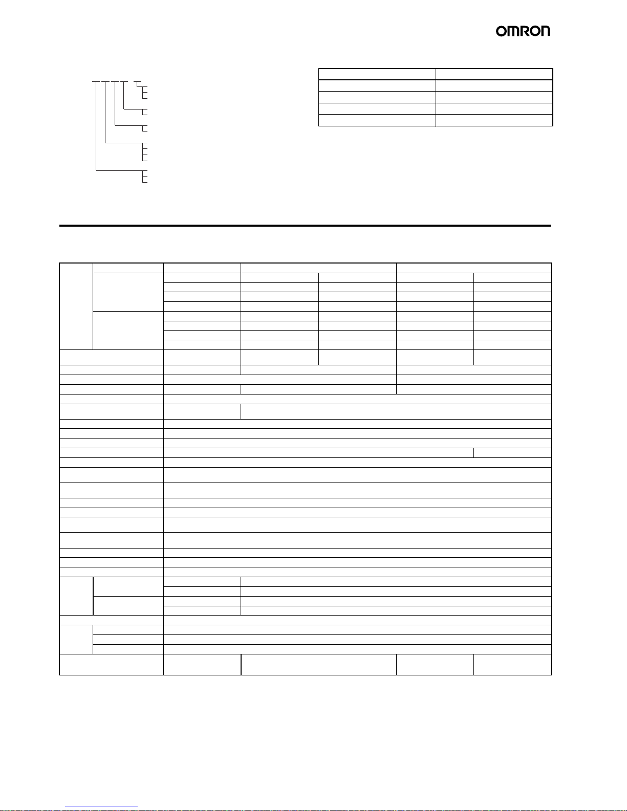
■Model Number Legend ■Accessories (Order Separately)
Note: E39-R1 is included in E3F3-R@@ and E3F3-R@@M.
Specifications
■Ratings/Characteristics
D: Reflector
L: Emitter
None: Reflective model
M: Metal housing
None: Plastic housing
1/2/3/4: Pre-wired
6/7/8/9: M12 connector
1: NPN L/ON
3: PNP L/ON
6: NPN D/ON
8: PNP D/ON
T: Through-beam
R: Retroreflective
D: Diffuse reflective
E3F3-@@@@-@
Name Model
Reflector E39-R1, E39-R3
Reflector (tape type) E39-RS1, E39-RS2, E39-RS3
Lens Cap E39-F31
Mounting Bracket Y92E-B18
Item Sensing method Through-beam Retroreflective Diffuse reflective
NPN output E3F3-T11 E3F3-R11 E3F3-R12 E3F 3-D 11 E3F3-D12
E3F3-T16 E3F3-R16 E3F3-R17 E3F3-D16 E3F3-D17
E3F3-T61 E3F3-R61 E3F3-R62 E3F3-D61 E3F3-D62
E3F3-T66 E3F3-R66 E3F3-R67 E3F3-D66 E3F3-D66
PNP output E3F3-T31 E3F3-R31 E3F3-R32 E3F3-D31 E3F3-D32
E3F3-T36 E3F3-R36 E3F3-R37 E3F3-D36 E3F3-D37
E3F3-T81 E3F3-R81 E3F3-R82 E3F3-D81 E3F3-D82
E3F3-T86 E3F3-R86 E3F3-R87 E3F3-D86 E3F3-D87
Sensing distance 5 m 3 m (Non-polarized when us-
ing E39-R1)
2 m (Non-polarized when using E39-R1)
100 mm 300 mm
Standard sensing object Opaque object: 11 mm min. Opaque object: 56 mm min. 100 × 100 mm white mat paper
Hysteresis --- 20% max. of sensing distance
Light source (wavelength) Infrared LED (860 mm) Red LED (680 mm) Infrared LED (860 mm)
Power supply voltage 12 to 24 VDC±10%, ripple (p-p): 10% max.
Current consumption 45 mA max. (light source and
receiver)
25 mA max.
Control outpu t Open collector transistor output, 100 mA max., residual voltage: 1 V max. at 100 mA
Protective circuit Output short-circuit protection, DC power supply reverse polarity protection
Response time 1.0 ms max.
Sensitivity adjustment --- Single- turn adjuster
Ambient illumination Incandescent lamp: 3,000 lx max., Sunlight: 10,000 lx max.
Ambient temperature Operating: –25 to 55 °C (with no icing or condensation)
Storage: –30 to 70 °C (with no icing or condensation)
Ambient humidity Operating: 45% to 85% (with no condensation)
Storage: 35% to 95% (with no condensation)
Insulation resistance 20 MΩ min. (at 500 VDC) between current carry parts and case
Dielectric strength 1,000 VAC at 50/60 Hz for 1 min between current carry parts and case
Vibration resistance
(destruction)
10 to 55 Hz, 1.5-mm double amplitude for 1 hour each in X, Y, and Z directions
Shock resistance
(destruction)
500 m/s
2
for 3 times each in X, Y, and Z directions
Degree of protection IEC 60529 IP66
Connecting method Pre-wired (standard length: 2 m)/M12 connector
Indicators Operation indicator (orange) [Power indicator of emitter (orange)]
Weight Pre-wired Metal: 200 g max. Metal housing: 100 g max.
Plastic: 170 g max. Plastic housing: 85 g max.
M12 connector Metal: 120 g max. Metal housing: 60 g max.
Plastic: 40 g max. Plastic housing: 20 g max.
Packing Nylon bag
Material Case Plastic: ABS, Metal: Nickel-brass
Lens PMMA
Accessories Screw nuts: ABS or Nickel-brass
Accessories Screw nuts (4),
Instruction sheet
Screw nuts (2),
E39-R1 reflector,
Instruction sheet
Screw nuts (2),
Instruction sheet
Screw nuts (2),
Instruction sheet,
Adjusting driver

E3F3 Photoelectric Sensor 3
Engineering Data
Parallel Operating Range (Typical)
Through-beam Models
E3F3-T@1@/T@6@
Operating Range (Typical)
Retroreflective Models
E3F3-R@1@/R@6@+E39-R1
Retroreflective Models
E3F3-R@2@/R@7@+E39-R1
Operating position Y (cm)
Operating position Y(cm)
Operating position Y(cm)
Distance X (m)
Distance X (m) Distance X (m)
−40
−30
−20
−10
0
10
20
30
40
−10
−5
0
5
10
61012428
X
Y
Sensor
Emitter
0.5 1 1.5 2 2.5 3 3.5
Y
Sensor
Reflector
Diffuse-reflective Models
E3F3-D@1@/D@6@
Diffuse-reflective Models
E3F3-D@2@/D@7@
Excess gain ratio
Distance (cm)
0 5 10 15 20 25
0.1
1
0.7
0.5
0.3
10
7
5
3
100
70
50
30
Excess Gain Ratio vs. Set Distance (Typical)
Through-beam Models
E3F3-T@1@/T@6@
Retroreflective Models
E3F3-R@1@/R@6@+E39-R1
Retroreflective Models
E3F3-R@2@/R@7@+E39-R1
Excess gain ratio
Excess gain ratio
Excess gain ratio
Distance (m)
Distance (m) Distance (m)
0.1
1
0.7
0.5
0.3
10
7
5
3
100
70
50
30
0.1
0.7
0.5
0.3
10
100
70
50
30
0 5 10 15 20 25 30
0123456
X
Excess gain ratio
Distance (cm)
0 20 40 60 80 100 120
0.1
1
0.7
0.5
0.3
10
7
5
3
100
70
50
30
Operating position Y (cm)
Distance X (cm)
Diffuse-reflective Models
E3F3-D
@2@/D@7@
-5
-4
-3
-2
-1
0
1
2
3
4
5
20 40 60 80 100 120
Sensor
X
Y
White paper
(100 x 100 mm)
Operating position Y (cm)
Distance X (cm)
Diffuse-reflective Models
E3F3-D
@1@/D@6@
3
4
5
-5
-4
-3
-2
-1
0
1
2
2 4 6 8 10 12 14
Sensor
X
Y
White paper
(100 x 100 mm)
16
−8
−10
−5
−3
0
3
5
8
10
1234
0.1
1
10
100
0123
4
Y
Sensor
Reflector
X
 Loading...