

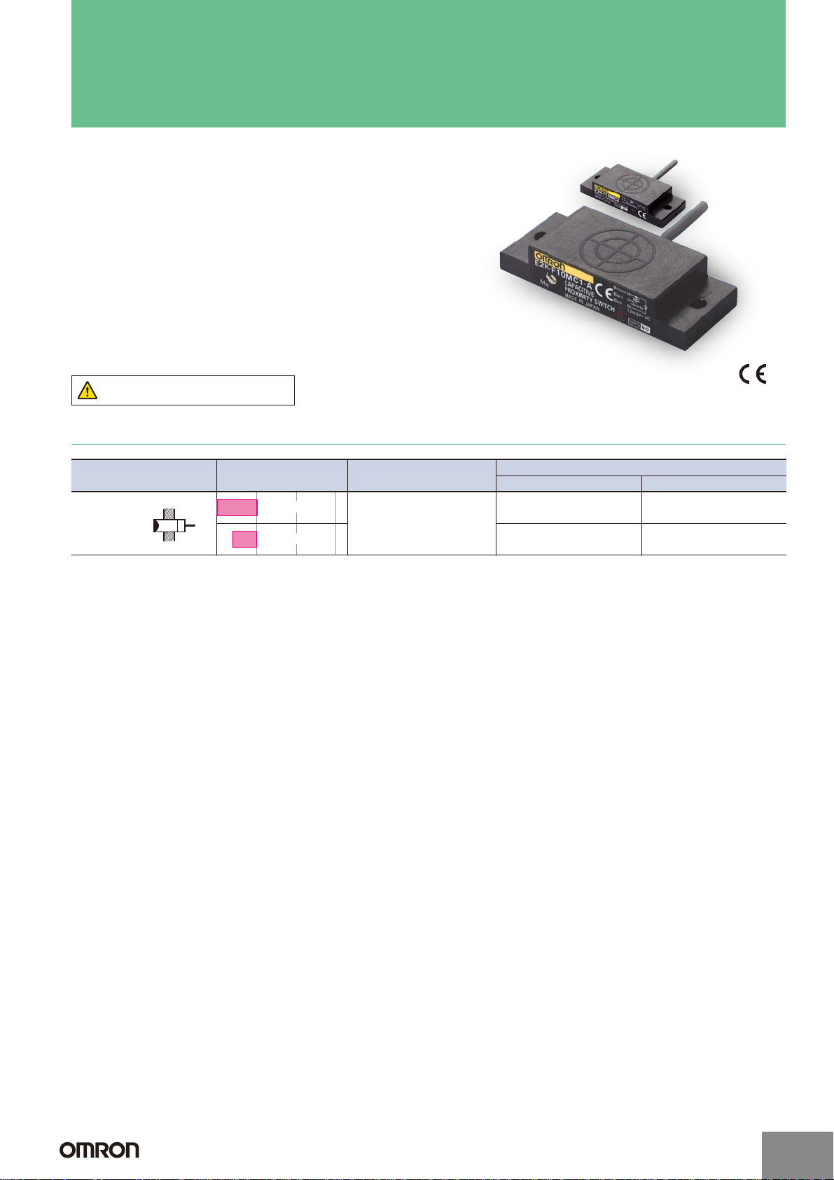
Flat Proximity Sensor
E2K-F
Saves Installation Space with a
Thickness of Only 10 mm
■ Flat, Built-in Amplifier Models offer excellent space
efficiency and provide a 10-mm sensing distance.
■ Detects both metallic and nonmetallic objects (water, oil,
glass, plastic, etc.).
■ Direct mounting onto a metallic surface is possible.
Be sure to read Safety Precautions on
page 3.
Ordering Information
Appearance Sensing distance Output configuration
Flat
Unshielded
10 mm
4 to 10 mm
DC 3-wire
NPN
Model/Operation mode
NO NC
E2K-F10MC1 E2K-F10MC2
E2K-F10MC1-A E2K-F10MC2-A
http://www.ia.omron.com/
(c)Copyright OMRON Corporation 2007 All Rights Reserved.
1
Ratings and Specifications
)
)
Item Model E2K-F10MC@-A E2K-F10MC@
Sensing distance 4 to 10 mm (adjustable with 12-turn adjuster) 10 mm r10%
Set distance 0 to 7.5 mm *
Differential travel 15% max. of sensing distance
Detectable object Conductors and dielectrics
Standard sensing object Grounded metal plate: 50 u 50 u 1 mm
Response frequency 100 Hz
Power supply voltage (operating
voltage range)
Current consumption 10 mA max. at 24 VDC
Control
output
Load current NPN open collector, 100 mA max. (at 30 VDC)
Residual voltage 1.5 V max. (Load current: 100 mA, Cable length: 2 m)
Indicators Detection indicator (red)
Operation mode (with sensing
object approaching)
Protection circuits Reverse polarity protection, Surge suppressor
Ambient temperature range Operating/Storage: 10 to 55qC (with no icing or condensation)
Ambient humidity range Operating/Storage: 35% to 95% Operating/Storage: 35% to 95%
Temperature influence r15% max. of sensing distance at 23qC in the temperature range of 10 to 55qC
Voltage influence r2.5% max. of sensing distance at rated voltage at rated voltage r10%
Insulation resistance 50 M: min. (at 500 VDC) between current-carrying parts and case
Dielectric strength 500 VAC, 50/60 Hz for 1 min between current-carrying parts and case
Vibration resistance Destruction: 10 to 55 Hz, 1.5-mm double amplitude for 2 hours each in X, Y, and Z directions
Shock resistance Destruction: 500 m/s2 3 times each in X, Y, and Z directions
Degree of protection IP64 (IEC) IP66 (IEC)
Connection method Pre-wired Models (Standard cable length: 2 m)
Weight (packed state) Approx. 35 g
Materials
Case
Sensing surface
Accessories Instruction manual
* The value for the E2K-F10MC@-A is when it is adjusted to 10 mm.
12 to 24 VDC (10 to 30 VDC), ripple (p-p): 10% max.
NO (Refer to the timing charts under I/O Circuit Diagrams on page 3 for details.)
Heat-resistant ABS
E2K-F
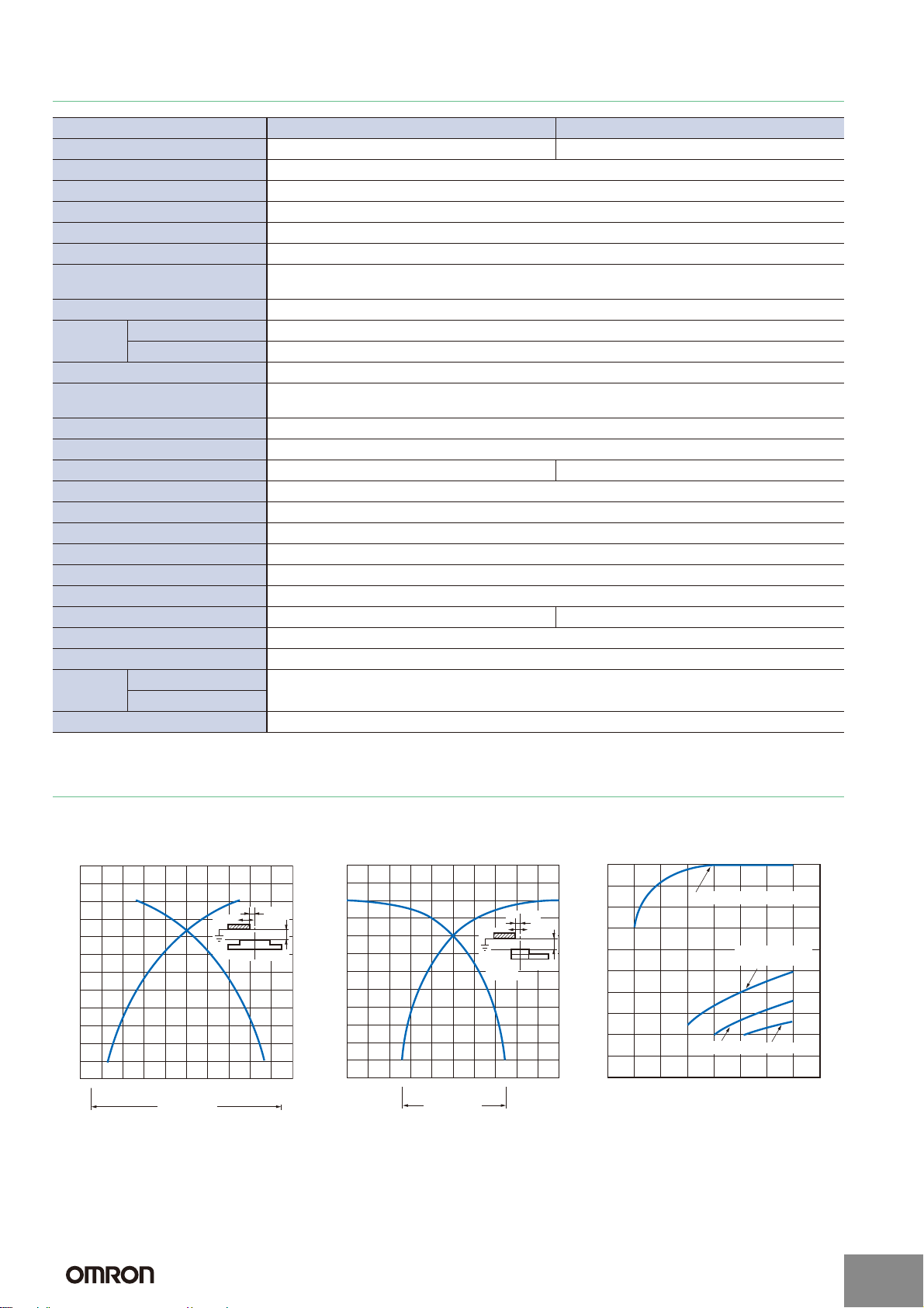
Engineering Data (Typical)
Sensing Area (Grounded Metal Plate) Influence of Sensing Object Size and
Material
201612840−4−8
10
9
8
Distance (mm)
7
6
5
4
3
2
1
100
Grounded metal plate (t = 1)
Non-grounded
metal plate (t = 10)
Glass (t = 10)
Side length of sensing object (mm
Phenol (t = 10)
80706050403020
12
11
10
9
Distance X (mm)
8
7
6
5
4
3
2
1
−12−16−20
Sensing Head
Left and
right
Distance Y (mm
12
11
Y
X
201612840−4−8
10
9
Distance X (mm)
8
7
6
5
4
3
2
1
−12−16−20
Sensing Head
Up and
down
Y
X
Distance Y
(mm)
http://www.ia.omron.com/
(c)Copyright OMRON Corporation 2007 All Rights Reserved.
2
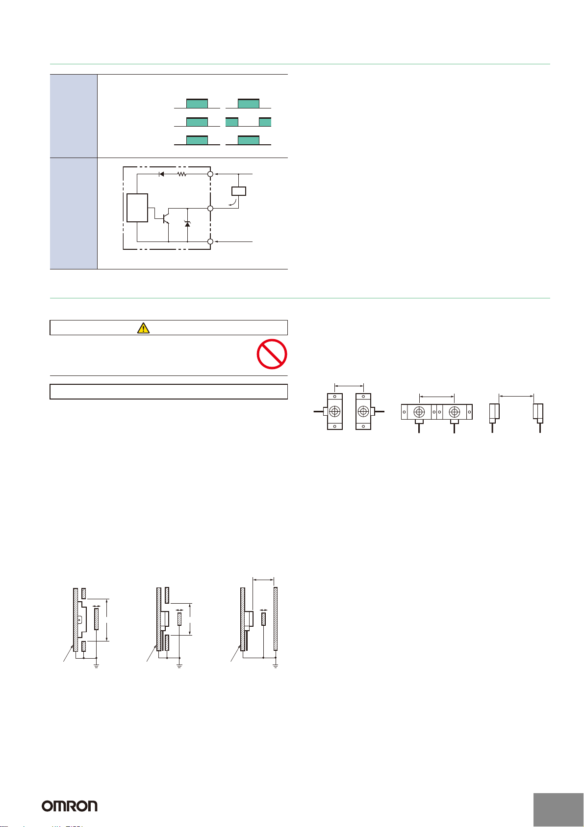
I/O Circuit Diagrams
V
Present
Not present
Timing
chart
Sensing
object
Output transistor
(load)
Detection
indicator (red)
E2K-F
NO Models NC Models
ON
OFF
ON
OFF
Output
circuit
100 Ω
Proximity
Sensor
main
circuit
* Load current: 100 mA max.
Brown
Black
Output
Blue
+V
Load
*
0
Safety Precautions
Refer to Warranty and Limitations of Liability.
WARNING
This product is not designed or rated for ensuring
safety of persons either directly or indirectly.
Do not use it for such purposes.
Precautions for Correct Use
Do not use this product under ambient conditions that exceed the
ratings.
● Design
Sensing Object Material
The E2K-F can detect almost any type of object. The sensing distance
of the E2K-F, however, will vary with the electrical characteristics of
the object, such as the conductance and inductance of the object, and
the water content and capacity of the object. The maximum sensing
distance of the E2K-F will be obtained if the object is made of
grounded metal. There are objects that cannot be detected indirectly.
Therefore, be sure to test the E2K-F in a trial operation with the
objects before using the E2K-F in actual applications.
Influence of Surrounding Metal
Separate the E2K-F from surrounding metal as shown below.
Mutual Interference
When mounting more than one E2K-F face-to-face or side-by-side,
separate them as shown below.
40 mm
50 mm
Close mounting possible Face-to-face mounting
50 mm
Effects of a High-frequency Electromagnetic Field
The E2K-F may malfunction if there is an ultrasonic washer, highfrequency generator, transceiver, portable telephone, or inverter
nearby.
For major measures, refer to Noise of Warranty and Limitations of
Liability for Photoelectric Sensors.
● Wiring
The characteristics of the E2K-F will not change if the cable is
extended. Extending the cable, however, will result in a voltage drop,
so do not extend the length past 200 m.
Metal
object
45 mm60 mm
Metal
object
http://www.ia.omron.com/
Metal
object
30 mm
(c)Copyright OMRON Corporation 2007 All Rights Reserved.
3
E2K-F
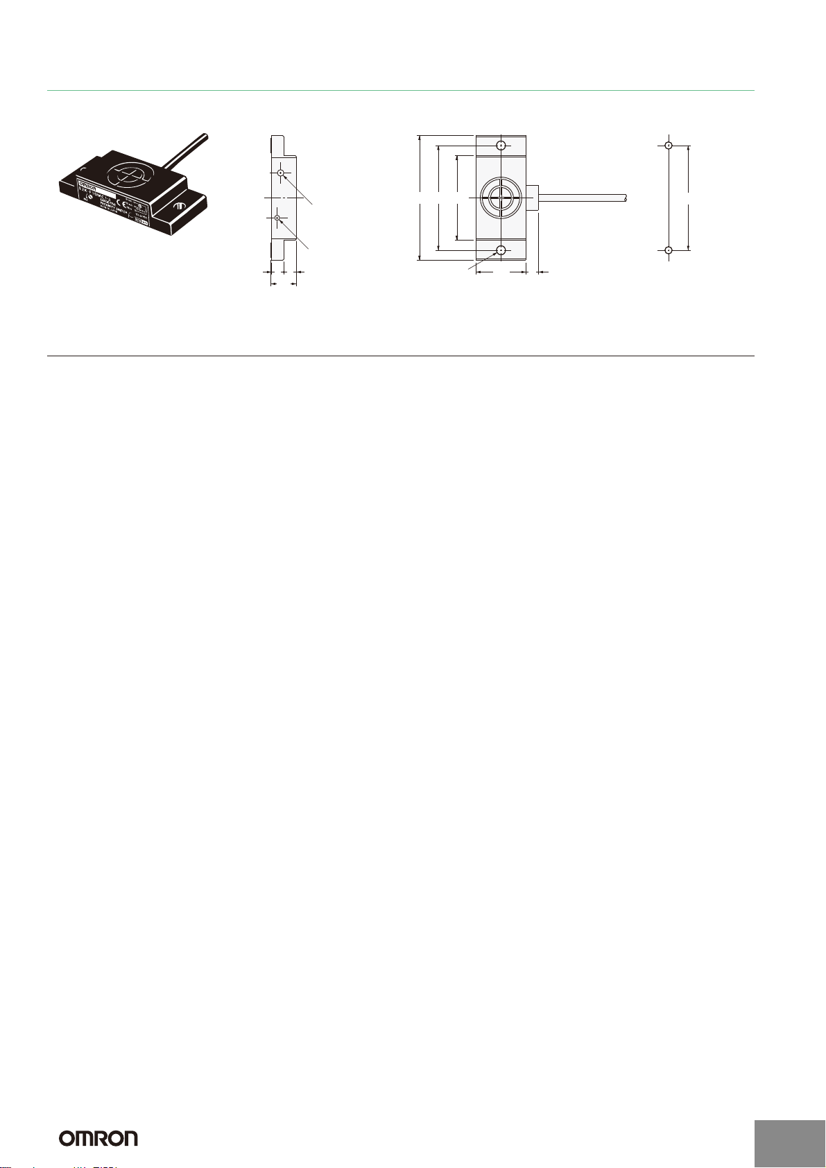
Dimensions (Unit: mm)
E2K-F
Two, 3.5 dia.
2
,
344250
Sensitivity adjuster *1
Detection indicator (red)
55
10.1
*1. Only the E2K-F10MC@-A has a sensitivity adjuster.
*2. 2.9-dia. vinyl-insulated round cable
(Conductor cross section: 0.14 mm
Insulator diameter: 0.9 mm), Standard length: 2 m.
20 5
Mounting Hole Dimensions
Two, M3 or 3.5 dia.
*2
42±0.2
http://www.ia.omron.com/
(c)Copyright OMRON Corporation 2007 All Rights Reserved.
4

Operating Procedures: Proximity Sensors
E2K-F
Sensitivity Adjustment
After the Sensor is mounted, adjust the detecting sensitivity using the (12-turn) sensitivity adjuster in the way shown below.
Status of the indicator when
the liquid level is aligned
with the setting position
Not lit
Lit
Note: While adjusting the sensitivity, do not put your hand on the Sensor and make sure that the cable is properly secured. Failure to observe these points may affect
the detection level.
Sensitivity adjuster Adjustment procedure
1
Turn the sensitivity adjuster counter-clockwise using a screwdriver until the indicator
lights.
2
1
Turn the sensitivity adjuster clockwise using a screwdriver until the indicator turns OFF.
Then, turn the sensitivity adjuster counter-clockwise until the indicator lights again.
http://www.ia.omron.com/
(c)Copyright OMRON Corporation 2007 All Rights Reserved.
5
 Loading...