

Page 1

OPERATION MANUAL
Function Blocks
CX-Programmer Ver.5.0
SYSMAC
WS02-CXPC1-E-V50
CS1-H, CJ1-H, CJ1M CPU Units
Cat.No. W438-E1-01
Page 2

CX-Programmer
Ver. 5.0
WS02-CXPC1-E-V50
CS1-H, CJ1-H, CJ1M CPU Units
Operation Manual
Function Blocks
Produced July 2004
Page 3

iv
Page 4

Notice:
r
f
OMRON products are manufactured for use according to proper procedures by a qualified operator
and only for the purposes described in this manual.
The following conventions are used to indicate and classify precautions in this manual. Always heed
the information provided with them. Failure to heed precautions can result in injury to people or damage to property.
!DANGER Indicates an imminently hazardous situation which, if not avoided, will result in death or
serious injury.
!WARNING Indicates a potentially hazardous situation which, if not avoided, could result in death or
serious injury.
!Caution Indicates a potentially hazardous situation which, if not avoided, may result in minor or
moderate injury, or property damage.
OMRON Product References
All OMRON products are capitalized in this manual. The word “Unit” is also capitalized when it refers to
an OMRON product, regardless of whether or not it appears in the proper name of the product.
The abbreviation “Ch,” which appears in some displays and on some OMRON products, often means
“word” and is abbreviated “Wd” in documentation in this sense.
The abbreviation “PLC” means Programmable Controller. “PC” is used, however, in some Programming Device displays to mean Programmable Controller.
Visual Aids
The following headings appear in the left column of the manual to help you locate different types of
information.
OMRON, 2004
All rights reserved. No part of this publication may be reproduced, stored in a retrieval system, or transmitted, in any form, o
by any means, mechanical, electronic, photocopying, recording, or otherwise, without the prior written permission o
OMRON.
No patent liability is assumed with respect to the use of the information contained herein. Moreover, because OMRON is constantly striving to improve its high-quality products, the information contained in this manual is subject to change without
notice. Every precaution has been taken in the preparation of this manual. Nevertheless, OMRON assumes no responsibility
for errors or omissions. Neither is any liability assumed for damages resulting from the use of the information contained in
this publication.
Note Indicates information of particular interest for efficient and convenient opera-
tion of the product.
1,2,3... 1. Indicates lists of one sort or another, such as procedures, checklists, etc.
v
Page 5

vi
Page 6

TABLE OF CONTENTS
PRECAUTIONS . . . . . . . . . . . . . . . . . . . . . . . . . . . . . . . . . . . xi
1 Intended Audience. . . . . . . . . . . . . . . . . . . . . . . . . . . . . . . . . . . . . . . . . . . . . . . . . . . . . . . . . xii
2 General Precautions. . . . . . . . . . . . . . . . . . . . . . . . . . . . . . . . . . . . . . . . . . . . . . . . . . . . . . . . xii
3 Safety Precautions . . . . . . . . . . . . . . . . . . . . . . . . . . . . . . . . . . . . . . . . . . . . . . . . . . . . . . . . . xii
4 Application Precautions. . . . . . . . . . . . . . . . . . . . . . . . . . . . . . . . . . . . . . . . . . . . . . . . . . . . .xiii
SECTION 1
Introduction. . . . . . . . . . . . . . . . . . . . . . . . . . . . . . . . . . . . . . . 1
1-1 Introducing the Function Blocks . . . . . . . . . . . . . . . . . . . . . . . . . . . . . . . . . . . . . . . . . . . . . . 2
1-2 Function Blocks. . . . . . . . . . . . . . . . . . . . . . . . . . . . . . . . . . . . . . . . . . . . . . . . . . . . . . . . . . . 7
1-3 Variables . . . . . . . . . . . . . . . . . . . . . . . . . . . . . . . . . . . . . . . . . . . . . . . . . . . . . . . . . . . . . . . . 13
1-4 Converting Function Block Definitions to Library Files . . . . . . . . . . . . . . . . . . . . . . . . . . . . 16
1-5 Usage Procedures. . . . . . . . . . . . . . . . . . . . . . . . . . . . . . . . . . . . . . . . . . . . . . . . . . . . . . . . . . 17
SECTION 2
Specifications . . . . . . . . . . . . . . . . . . . . . . . . . . . . . . . . . . . . . . 19
2-1 Function Block Specifications. . . . . . . . . . . . . . . . . . . . . . . . . . . . . . . . . . . . . . . . . . . . . . . . 21
2-2 Instance Specifications . . . . . . . . . . . . . . . . . . . . . . . . . . . . . . . . . . . . . . . . . . . . . . . . . . . . . 30
2-3 Restrictions on Function Blocks . . . . . . . . . . . . . . . . . . . . . . . . . . . . . . . . . . . . . . . . . . . . . . 37
2-4 Function Block Applications Guidelines. . . . . . . . . . . . . . . . . . . . . . . . . . . . . . . . . . . . . . . . 42
2-5 Precautions for Instructions with Operands Specifying the First or Last of Multiple Words 49
2-6 Instruction Support and Operand Restrictions. . . . . . . . . . . . . . . . . . . . . . . . . . . . . . . . . . . . 52
2-7 CPU Unit Function Block Specifications . . . . . . . . . . . . . . . . . . . . . . . . . . . . . . . . . . . . . . . 104
2-8 Number of Function Block Program Steps and Instance Execution Time . . . . . . . . . . . . . . 108
SECTION 3
Creating Function Blocks. . . . . . . . . . . . . . . . . . . . . . . . . . . . 111
3-1 Procedural Flow. . . . . . . . . . . . . . . . . . . . . . . . . . . . . . . . . . . . . . . . . . . . . . . . . . . . . . . . . . . 112
3-2 Procedures . . . . . . . . . . . . . . . . . . . . . . . . . . . . . . . . . . . . . . . . . . . . . . . . . . . . . . . . . . . . . . . 114
Appendices
A Data Types . . . . . . . . . . . . . . . . . . . . . . . . . . . . . . . . . . . . . . . . . . . . . . . . . . . . . . . . . . . . . . 137
B Structured Text (ST Language) Specifications . . . . . . . . . . . . . . . . . . . . . . . . . . . . . . . . . . . 139
C External Variables . . . . . . . . . . . . . . . . . . . . . . . . . . . . . . . . . . . . . . . . . . . . . . . . . . . . . . . . . 161
Index. . . . . . . . . . . . . . . . . . . . . . . . . . . . . . . . . . . . . . . . . . . . . 163
Revision History . . . . . . . . . . . . . . . . . . . . . . . . . . . . . . . . . . . 165
vii
Page 7

TABLE OF CONTENTS
viii
Page 8

About this Manual:
This manual describes the function blocks and related functionality of the CX-Programmer Ver. 5.0
used together with CS1-H, CJ1-H, and CJ1M CPU Units with unit version 3.0 or later, and includes the
sections described on the next page. The CX-Programmer Ver. 5.0 is software that enables the personal computer to be used as a function block programming device, and can be used only for SYSMAC CS-series and CJ-series CPU Units that support function blocks.
The CX-Programmer Ver. 5.0 function block functions have been enhanced. This manual describes
only CX-Programmer Ver. 5.0 operations that are related to functions blocks. For operations not related
to function blocks, refer to the CX-Programmer Operation Manual (enclosed, Cat. No. W437). This
manual also provides only information related to function blocks for the CS1-H, CJ1-H, and CJ1M CPU
Units. For other information, refer to the CS/CJ-series manuals.
Please read this manual and related manuals carefully and be sure you understand the information
provided before attempting to install or operate the CX-Programmer Ver. 5.0 or the CS1-H, CJ1-H, or
CJ1M CPU Units. Be sure to read the precautions provided in the following section.
Manuals Related to the CX-Programmer Ver. 5.0
Name Cat. No. Contents
SYSMAC WS02-CXPC1-E-V50
CX-Programmer Ver. 5.0 Operation Manual
Function Blocks
(CS1G-CPU
CJ1G-CPU@@H, CJ1H-CPU@@H,
CJ1M-CPU
SYSMAC WS02-CXPC1-E-V50
CX-Programmer Operation Manual
@@H, CS1H-CPU@@H,
@@ CPU Units)
W438 Describes the functionality unique to the CX-Programmer Ver.
5.0 and CS/CJ-series CPU Units with unit version 3.0 or later
based on function blocks. Functionality that is the same as
that of the CX-Programmer is described in W437 (enclosed).
W437 Provides information on how to use the CX-Programmer for
all functionality except for function blocks.
Manuals Related to the CS1-H, CJ1-H, CJ1M CPU Units
Name Cat. No. Contents
SYSMAC CS Series
CS1G/H-CPU@@-EV1, CS1G/H-CPU@@H
Programmable Controllers
Operation Manual
SYSMAC CJ Series
CJ1G-CPU@@, CJ1G/H-CPU@@H, CJ1GCPU@@P, C J 1 M - C P U @@
Programmable Controllers
Operation Manual
W339 Provides an outline of and describes the design, installation,
maintenance, and other basic operations for the CS-series
PLCs.
The following information is included:
An overview and features
The system configuration
Installation and wiring
I/O memory allocation
Troubleshooting
Use this manual together with the W394.
W393 Provides an outline of and describes the design, installation,
maintenance, and other basic operations for the CJ-series
PLCs.
The following information is included:
An overview and features
The system configuration
Installation and wiring
I/O memory allocation
Troubleshooting
Use this manual together with the W394.
ix
Page 9

Name Cat. No. Contents
SYSMAC CS/CJ Series
CS1G/H-CPU@@-EV1, CS1G/H-CPU@@H,
CJ1G-CPU@@, CJ1G/H-CPU@@H, CJ1GCPU@@P, C J 1 M - C P U @@
Programmable Controllers
Programming Manual
SYSMAC CS/CJ Series
CS1G/H-CPU@@-EV1, CS1G/H-CPU@@H,
CJ1G-CPU@@, CJ1G/H-CPU@@H, CJ1GCPU@@P, C J 1 M - C P U @@
Programmable Controllers
Instructions Reference Manual
SYSMAC CS/CJ Series
CS1G/H-CPU@@-EV1, CS1G/H-CPU@@H,
CS1W-SCB21-V1/41-V1, CS1W-SCU21/41,
CJ1G-CPU@@, CJ1G/H-CPU@@H, CJ1GCPU@@P, C J 1 M - C P U @@, CJ1W-SCU21-V1/
41-V1
Communications Commands
Reference Manual
W394 Describes programming and other methods to use the func-
tions of the CS/CJ-series PLCs.
The following information is included:
Programming
Ta sk s
File memory
Other functions
Use this manual together with the W339 or W393.
W340 Describes the ladder diagram programming instructions sup-
ported by CS/CJ-series PLCs.
When programming, use this manual together with the Oper-
ation Manual (CS1: W339 or CJ1: W393) and Programming
Manual (W394).
W342 Describes the communications commands that can be
addressed to CS/CJ-series CPU Units.
The following information is included:
C-series (Host Link) commands
FINS commands
Note: This manual describes commands that can be sent to
the CPU Unit without regard for the communications path,
which can be through a serial communications port on the
CPU Unit, a communications port on a Serial Communications Unit/Board, or a port on any other Communications
Unit.
Overview of Contents
Precautions provides general precautions for using the CX-Programmer Ver. 5.0.
Section 1 introduces the function block functionality of the CX-Programmer and explains the features
that are not contained in the non-function block version of CX-Programmer.
Section 2 provides specifications for reference when using function blocks, including specifications on
function blocks, instances, and compatible PLCs, as well as usage precautions and guidelines.
Section 3 describes the procedures for creating function blocks on the CX-Programmer.
The Appendices provide information on data types, structure text specifications, and external vari-
ables.
!WARNING Failure to read and understand the information provided in this manual may result in per-
sonal injury or death, damage to the product, or product failure. Please read each section
in its entirety and be sure you understand the information provided in the section and
related sections before attempting any of the procedures or operations given.
x
Page 10

PRECAUTIONS
This section provides general precautions for using the CX-Programmer Ver. 5.0 and the Programmable Logic Controller.
The information contained in this section is important for the safe and reliable application of the CX-Programmer
Ver. 5.0 and Programmable Controller. You must read this section and understand the information contained before
attempting to set up or operate the CX-Programmer Ver. 5.0 and Programmable Controller.
1 Intended Audience . . . . . . . . . . . . . . . . . . . . . . . . . . . . . . . . . . . . . . . . . . . . . xii
2 General Precautions . . . . . . . . . . . . . . . . . . . . . . . . . . . . . . . . . . . . . . . . . . . . xii
3 Safety Precautions. . . . . . . . . . . . . . . . . . . . . . . . . . . . . . . . . . . . . . . . . . . . . . xii
4 Application Precautions . . . . . . . . . . . . . . . . . . . . . . . . . . . . . . . . . . . . . . . . . xiii
xi
Page 11

Intended Audience 1
1 Intended Audience
This manual is intended for the following personnel, who must also have
knowledge of electrical systems (an electrical engineer or the equivalent).
• Personnel in charge of installing FA systems.
• Personnel in charge of designing FA systems.
• Personnel in charge of managing FA systems and facilities.
2 General Precautions
The user must operate the product according to the performance specifications described in the operation manuals.
Before using the product under conditions which are not described in the
manual or applying the product to nuclear control systems, railroad systems,
aviation systems, vehicles, combustion systems, medical equipment, amusement machines, safety equipment, and other systems, machines, and equipment that may have a serious influence on lives and property if used
improperly, consult your OMRON representative.
Make sure that the ratings and performance characteristics of the product are
sufficient for the systems, machines, and equipment, and be sure to provide
the systems, machines, and equipment with double safety mechanisms.
This manual provides information for programming and operating the product.
Be sure to read this manual before attempting to use the product and keep
this manual close at hand for reference during operation.
!WARNING It is extremely important that a PLC and all PLC Units be used for the speci-
fied purpose and under the specified conditions, especially in applications that
can directly or indirectly affect human life. You must consult with your
OMRON representative before applying a PLC System to the above-mentioned applications.
3 Safety Precautions
!WARNING Confirm safety sufficiently before transferring I/O memory area status from the
CX-Programmer Ver. 5.0 to the actual CPU Unit. The devices connected to
Output Units may malfunction, regardless of the operating mode of the CPU
Unit. Caution is required in respect to the following functions.
• Transferring from the CX-Programmer to real I/O (CIO Area) in the CPU
Unit using the PLC Memory Window.
• Transferring from file memory to real I/O (CIO Area) in the CPU Unit using
the Memory Card Window.
!Caution Variables must be specified either with AT settings (or external variables), or
the variables must be the same size as the data size to be processed by the
instruction when specifying the first or last address of multiple words in the
instruction operand.
xii
1. If a non-array variable with a different data size and without an AT setting
is specified, the CX-Programmer will output an error when compiling.
2. Array Variable Specifications
Page 12

Application Precautions 4
• When the size to be processed by the instruction operand is fixed:
The number of array elements must be the same as the number of elements to be processed by the instruction. Otherwise, the CX-Programmer
will output an error when compiling.
• When the size to be processed by the instruction operand is not fixed:
The number of array elements must be greater than or the same as the
size specified in the other operands.
• If the other operand specifying a size is a constant, the CX-Programmer Ver. 5.0 will output an error when compiling.
• If the other operand specifying a size is a variable, the CX-Programmer
Ver. 5.0 will not output an error when compiling, even if the size of the
array variable is not the same as that specified by the other operand
(variable). A warning message, however, will be displayed. In particular, if the number of array elements is less than the size specified by
the other operand (e.g., the size of the instruction operand is 16, and
the number of elements registered in the actual variable table is 10),
the instruction will execute read/write processing for the area that exceeds the number of elements. For example, read/write processing will
be executed for the 6 words following those for the number of elements
registered in the actual variable table. If these words are used for other
instructions (including internal variable allocations), unexpected operation will occur, which may result in serious accidents.
Check that the system will not be adversely affected if the size of the
variable specified in the operand is less than the size in the operand
definition before starting PLC operations.
!Caution Confirm safety at the destination node before transferring a program to
another node or changing contents of the I/O memory area. Doing either of
these without confirming safety may result in injury.
!Caution Execute online editing only after confirming that no adverse effects will be
caused by extending the cycle time. Otherwise, the input signals may not be
readable.
!Caution Confirm safety sufficiently before monitoring power flow and present value
status in the Ladder Section Window or when monitoring present values in the
Watch Window. If force-set/reset or set/reset operations are inadvertently performed by pressing short-cut keys, the devices connected to Output Units
may malfunction, regardless of the operating mode of the CPU Unit.
4 Application Precautions
Observe the following precautions when using the CX-Programmer.
• User programs cannot be uploaded to the CX-Programmer.
• Observe the following precautions before starting the CX-Programmer.
• Exit all applications not directly related to the CX-Programmer. Particularly exit any software such as screen savers, virus checkers, E-mail
or other communications software, and schedulers or other applications that start up periodically or automatically.
• Disable sharing hard disks, printers, or other devices with other computers on any network.
xiii
Page 13

Application Precautions 4
• With some notebook computers, the RS-232C port is allocated to a
modem or an infrared line by default. Following the instructions in documentation for your computer and enable using the RS-232C port as
a normal serial port.
• With some notebook computers, the default settings for saving energy
do not supply the rated power to the RS-232C port. There may be both
Windows settings for saving energy, as well as setting for specific computer utilities and the BIOS. Following the instructions in documentation for your computer, disable all energy saving settings.
• Do not turn OFF the power supply to the PLC or disconnect the connecting cable while the CX-Programmer is online with the PLC. The computer
may malfunction.
• Confirm that no adverse effects will occur in the system before attempting
any of the following. Not doing so may result in an unexpected operation.
• Changing the operating mode of the PLC.
• Force-setting/force-resetting any bit in memory.
• Changing the present value of any word or any set value in memory.
• Check the user program for proper execution before actually running it on
the Unit. Not checking the program may result in an unexpected operation.
• When online editing is performed, the user program and parameter area
data in CS1-H, CJ1-H, and CJ1M CPU Units is backed up in the built-in
flash memory. The BKUP indicator will light on the front of the CPU Unit
when the backup operation is in progress. Do not turn OFF the power
supply to the CPU Unit when the BKUP indicator is lit. The data will not be
backed up if power is turned OFF. To display the status of writing to flash
memory on the CX-Programmer, select Display dialog to show PLC Mem-
ory Backup Status in the PLC properties and then select Windows - PLC
Memory Backup Status from the View Menu.
• Programs including function blocks (ladder programming language or
structured text (ST) language) can be downloaded or uploaded in the
same way as standard programs that do not contain function blocks.
Tasks including function blocks, however, cannot be downloaded in task
units (uploading is possible).
• If a user program containing function blocks created on the CX-Programmer Ver. 5.0 or later is downloaded to a CPU Unit that does not support
function blocks (CS/CJ-series CPU Units with unit version 2.0 or earlier),
all instances will be treated as illegal commands and it will not be possible
to edit or execute the user program.
• If the input variable data is not in boolean format, and numerical values
only (e.g., 20) are input in the parameters, the actual value in the CIO
Area address (e.g., 0020) will be passed. Therefore, be sure to include an
&, #, or +, - prefix before inputting the numerical value.
• Addresses can be set in input parameters, but the address itself cannot
be passed as an input variable. (Even if an address is set as an input
parameter, the value passed to the function block will be that for the size
of data in the input variable.) Therefore, an input variable cannot be used
as the operand of the instruction in the function block when the operand
specifies the first or last of multiple words. Use an internal variable with an
AT setting. Alternatively, specify the first or last element in an internal
array variable.
xiv
Page 14

Application Precautions 4
• Values are passed in a batch from the input parameters to the input variables before algorithm execution (not at the same time as the instructions
in the algorithm are executed). Therefore, to pass the value from a
parameter to an input variable when an instruction in the function block
algorithm is executed, use an internal variable or external variable instead
of an input variable. The same applies to the timing for writing values to
the parameters from output variables.
• Always use internal variables with AT settings in the following cases.
• The addresses allocated to Basic I/O Units, Special I/O Units, and
CPU Bus Units cannot be registered to global symbols, and these variables cannot be specified as external variables (e.g., the data set for
global variables may not be stable).
• Use internal variables when Auxiliary Area bits other than those preregistered to external variables are registered to global symbols and
these variables are not specified as external variables.
• Use internal variables when specifying PLC addresses for another
node on the network: For example, the first destination word at the remote node for SEND(090) and the first source word at the remote
node for RECV(098).
• Use internal variables when the first or last of multiple words is specified by an instruction operand and the operand cannot be specified as
an internal array variable (e.g., the number of array elements cannot
be specified).
xv
Page 15

Application Precautions 4
xvi
Page 16

SECTION 1
Introduction
This section introduces the function block functionality of the CX-Programmer and explains the features that are not
contained in the non-function block version of CX-Programmer.
1-1 Introducing the Function Blocks. . . . . . . . . . . . . . . . . . . . . . . . . . . . . . . . . . . 2
1-1-1 Overview and Features . . . . . . . . . . . . . . . . . . . . . . . . . . . . . . . . . . . 2
1-1-2 Function Block Specifications . . . . . . . . . . . . . . . . . . . . . . . . . . . . . 3
1-1-3 Files Created with CX-Programmer Ver. 5.0 . . . . . . . . . . . . . . . . . . 4
1-1-4 CX-Programmer Ver. 5.0 Function Block Menus . . . . . . . . . . . . . . 5
1-2 Function Blocks . . . . . . . . . . . . . . . . . . . . . . . . . . . . . . . . . . . . . . . . . . . . . . . 7
1-2-1 Outline . . . . . . . . . . . . . . . . . . . . . . . . . . . . . . . . . . . . . . . . . . . . . . . 7
1-2-2 Advantages of Function Blocks . . . . . . . . . . . . . . . . . . . . . . . . . . . . 7
1-2-3 Function Block Structure . . . . . . . . . . . . . . . . . . . . . . . . . . . . . . . . . 8
1-3 Variables . . . . . . . . . . . . . . . . . . . . . . . . . . . . . . . . . . . . . . . . . . . . . . . . . . . . . 13
1-3-1 Introduction. . . . . . . . . . . . . . . . . . . . . . . . . . . . . . . . . . . . . . . . . . . . 13
1-3-2 Variable Usage and Properties . . . . . . . . . . . . . . . . . . . . . . . . . . . . . 13
1-3-3 Variable Properties . . . . . . . . . . . . . . . . . . . . . . . . . . . . . . . . . . . . . . 14
1-3-4 Variable Properties and Variable Usage . . . . . . . . . . . . . . . . . . . . . . 15
1-3-5 Internal Allocation of Variable Addresses . . . . . . . . . . . . . . . . . . . . 15
1-4 Converting Function Block Definitions to Library Files . . . . . . . . . . . . . . . . 16
1-5 Usage Procedures . . . . . . . . . . . . . . . . . . . . . . . . . . . . . . . . . . . . . . . . . . . . . . 17
1-5-1 Creating Function Blocks and Executing Instances . . . . . . . . . . . . . 17
1-5-2 Reusing Function Blocks . . . . . . . . . . . . . . . . . . . . . . . . . . . . . . . . . 18
1
Page 17

Introducing the Function Blocks Section 1-1
1-1 Introducing the Function Blocks
1-1-1 Overview and Features
The CX-Programmer Ver. 5.0 is a Programming Device that can use standard
IEC 61131-3 function blocks. The CX-Programmer Ver. 5.0 function block
function is supported for CS/CJ-series CPU Units with unit version 3.0 or later
and has the following features.
• User-defined processes can be converted to block format by using function blocks.
• Function block algorithms can be written in the ladder programming language or in the structured text (ST) language. (See note.)
• When ladder programming is used, ladder programs created with nonCX-Programmer Ver. 4.0 or earlier can be reused by copying and pasting.
• When ST language is used, it is easy to program mathematical processes that would be difficult to enter with ladder programming.
Note The ST language is an advanced language for industrial control
(primarily Programmable Logic Controllers) that is described in IEC
61131-3. The ST language supported by CX-Programmer conforms to the IEC 61131-3 standard.
• Function blocks can be created easily because variables do not have to
be declared in text. They are registered in variable tables.
A variable can be registered automatically when it is entered in a ladder or
ST program. Registered variables can also be entered in ladder programs
after they have been registered in the variable table.
• A single function block can be converted to a library function as a single
file, making it easy to reuse function blocks for standard processing.
• A program check can be performed on a single function block to easily
confirm the function block’s reliability as a library function.
• Programs containing function blocks (ladder programming language or
structured text (ST) language) can be downloaded or uploaded in the
same way as standard programs that do not contain function blocks.
Tasks containing function blocks, however, cannot be downloaded in task
units (uploading is possible).
• One-dimensional array variables are supported, so data handling is easier for many applications.
Note The IEC 61131 standard was defined by the International Electrotechnical
Commission (IEC) as an international programmable logic controller (PLC)
standard. The standard is divided into 7 parts. Specifications related to PLC
programming are defined in Part 3 Textual Languages (IEC 61131-3).
2
Page 18

Introducing the Function Blocks Section 1-1
1-1-2 Function Block Specifications
For specifications that are not listed in the following table, refer to the CX-Programmer Ver. 5.0 Operation Manual (W437).
Item Specifications
Model number WS02-CXPC1-E-V50
Setup disk CD-ROM
Compatible CPU Units CS/CJ-series CS1-H, CJ1-H, and CJ1M CPU Units with unit version 3.0 or
Compatible
computers
Computer IBM PC/AT or compatible
CPU 133 MHz Pentium or faster with Windows 98, SE, or NT 4.0 (with service pack
OS Microsoft Windows 95, 98, SE, Me, 2000, XP, or NT 4.0 (with service pack 6
Memory 64 Mbytes min. with Windows 98, SE, or NT 4.0 (with service pack 6 or
Hard disk space 100 Mbytes min. available disk space
Monitor
CD-ROM drive One CD-ROM drive min.
COM port One RS-232C port min.
later are compatible.
Device Type CPU Type
• CS1G-H CS1G-CPU42H/43H/44H/45H
• CS1H-H CS1H-CPU63H/64H/65H/66H/67H
• CJ1G-H CJ1G-CPU42H/43H/44H/45H
• CJ1H-H CJ1H-CPU65H/66H/67H
• CJ1M CJ1M-CPU11/12/13/21/22/23
Note If a user program containing function blocks created on the CX-Pro-
grammer Ver. 5.0 or later is downloaded to a CPU Unit that does not
support function blocks (CS/CJ-series CPU Units with unit version 2.0
or earlier), all instances will be treated as illegal commands and it will
not be possible to edit or execute the user program.
CS/CJ Series Function Restrictions
• Instructions Not Supported in Function Block Definitions
Block Program Instructions (BPRG and BEND), Subroutine Instructions
(SBS, GSBS, RET, MCRO, and SBN), Jump Instructions (JMP, CJP, and
CJPN), Step Ladder Instructions (STEP and SNXT), Immediate Refresh
Instructions (!), I/O REFRESH (IORF), ONE-MS TIMER (TMHH)
For details, refer to 2-3 Restrictions on Function Blocks.
6 or higher)
or higher)
higher)
Refer to Computer System Requirements below for details.
SVGA (800
Note Use “small font” for the font size.
× 600 pixels) min.
3
Page 19
Introducing the Function Blocks Section 1-1
Item Specifications
Functions not
supported by
CX-Programmer Ver. 4.0
or earlier.
Defining
and creating function blocks
Creating
instances
Storing
function
blocks as
files
Number of
function block
definitions
Function
block names
Variables Variable names 30,000 characters max.
Language Function blocks can be created in ladder programming language or structured
Number of
instances
Instance
names
Project files The project file (.cxp/cxt) Includes function block definitions and instances.
Program files The file memory program file (*.obj) includes function block definitions and
Function
block library
files
CS1-H/CJ1-H CPU Units:
• Suffix -CPU44H/45H/64H/65H/66H/67H: 1,024 max. per CPU Unit
• Suffix -CPU42H/43H/63H: 128 max. per CPU Unit
CJ1M CPU Units:
• CJ1M-CPU11/12/13/21/22/23: 128 max. per CPU Unit
64 characters max.
Variable types Inputs, Outputs, Internals, and Externals
Number of I/O variables in
function block definitions
Allocation of addresses
used by variables
Actual address specifica-
tion
Array specifications Supported (one-dimensional arrays only)
text (ST, see note).
CS1-H/CJ1-H CPU Units:
• Suffix -CPU44H/45H/64H/65H/66H/67H: 2,048 max. per CPU Unit
• Suffix -CPU42H/43H/63H: 256 max. per CPU Unit
CJ1M CPU Units:
CJ1M-CPU11/12/13/21/22/23: 256 max. per CPU Unit
30,000 characters max.
instances.
Each function block definition can be stored as a single file (.cxf) for reuse in
other projects.
64 max. (not including EN and ENO)
Automatic allocation (The allocation range can
be set by the user.)
Supported
Note The structured text (ST language) conforms to the IEC 61131-3 standard, but
CX-Programmer Ver. 5.0 supports only assignment statements, selection
statements (CASE and IF statements), iteration statements (FOR, WHILE,
REPEAT, and EXIT statements), RETURN statements, arithmetic operators,
logical operators, comparison functions, numeric functions, and comments.
For details, refer to Appendix B Structured Text (ST Language) Specifications.
1-1-3 Files Created with CX-Programmer Ver. 5.0
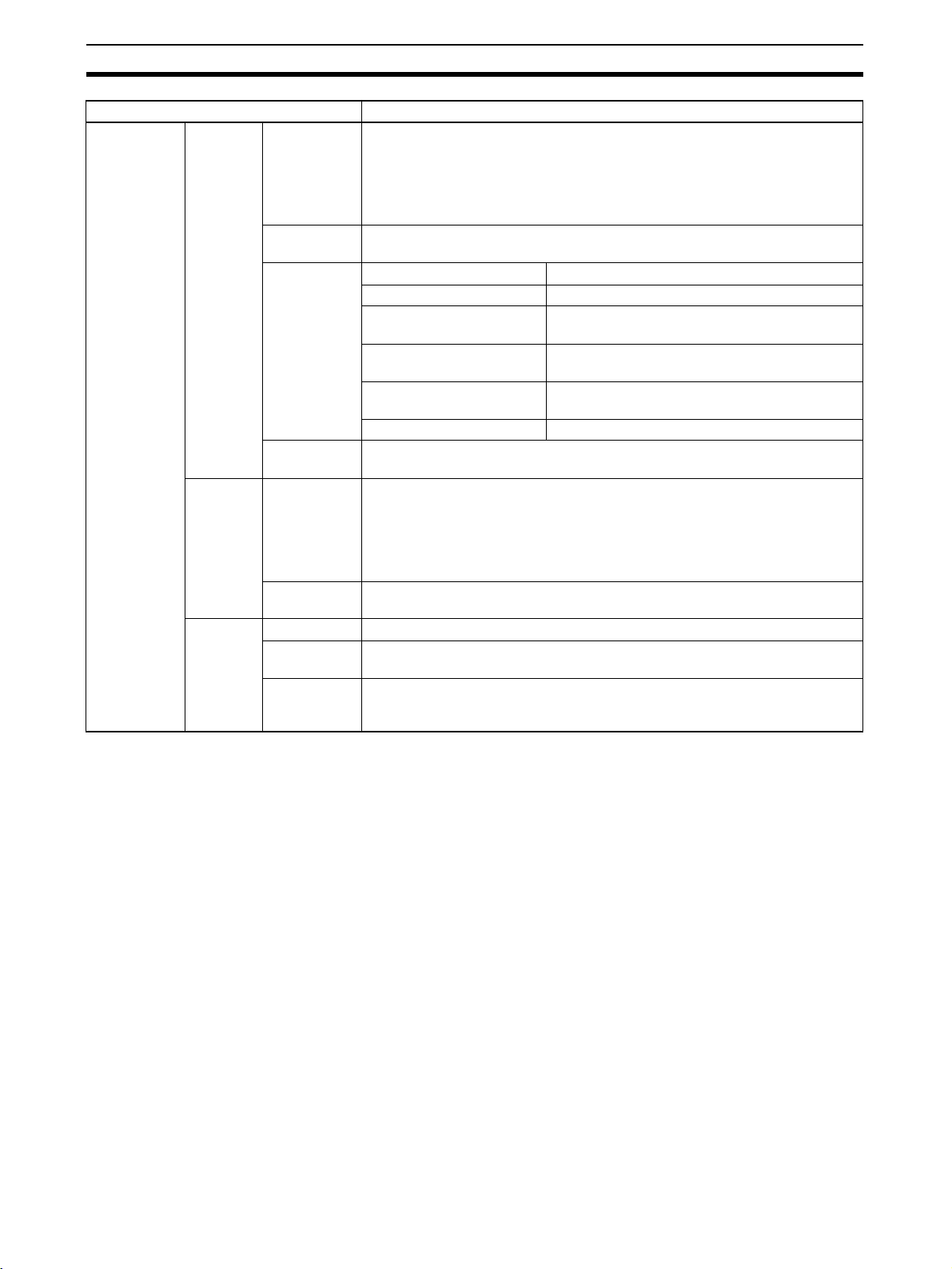
Project Files (*.cxp) and
File Memory Program
Files (*.obj)
Projects created using CX-Programmer that contain function block definitions
and projects with instances are saved in the same standard project files
(*.cxp) and file memory program files (*.obj).
The following diagram shows the contents of a project. The function block definitions are created at the same directory level as the program within the relevant PLC directory.
4
Page 20
Introducing the Function Blocks Section 1-1
Project file (.cxp)
Global symbol table
I/O table
PLC Setup
PLC memory table
Program (with rung comments)
Local symbol table
Section 1 (with instances)
Section 2 (with instances)
END section (with instances)
Fun ction block def in itions
FunctionBlock1
FunctionBlock2
Instances created
in program
sections.
Function Block Library
Files (*.cxf)
PLC1
PLC2
A function block definition created in a project with CX-Programmer Ver. 5.0
can be saved as a file (1 definition = 1 file), enabling definitions to be loaded
into other programs and reused.
Project Text Files
Containing Function
Data equivalent to that in project files created with CX-Programmer Ver. 5.0
(*.cxp) can be saved as CXT text files (*.cxt).
Blocks (*.cxt)
1-1-4 CX-Programmer Ver. 5.0 Function Block Menus
The following tables list CX-Programmer Ver. 5.0 menus related to function
blocks. For details on all menus, refer to the CX-Programmer Ver. 5.0 Opera-
tion Manual (W437).
Each function block can be
stored in a separate
definition file (.cxf).
Main Menu
Main menu Submenu Shortcut Function
File Func-
tion
Block
Edit Update Function Block --- When a function block definition’s I/O variables have been changed
Insert Function Block Invocation F Creates an instance in the program (section) at the present cursor
Function Block Parameter P When the cursor is located to the left of an input variable or the right
PLC Func-
tion
Block
Memory
Load Function
Block from File
Save Function
Block to File
Function Block
Memory Allocation
Function Block
Memory Statistics
Function Block
Instance Address
Optimize Function
Memory
--- Reads the saved function block library files (*.cxf).
--- Saves the created function block definitions to a file ([function block
library file]*.cxf).
after the instance was created, an error will be indicated by displaying the instance’s left bus bar in red. This command updates the
instance with the new information and clears the error.
location.
of an output variable, sets the variable’s input or output parameter.
--- Sets the range of addresses (function block instance areas) internally allocated to the selected instance’s variables.
--- Checks the status of the addresses internally allocated to the
selected instance’s variables.
--- Checks the addresses internally allocated to each variable in the
selected instance.
--- Optimizes the allocation of addresses internally allocated to variables.
5
Page 21
Introducing the Function Blocks Section 1-1
Main Popup Menus
Popup Menu for Function Block Definitions
Popup menu Function
Insert Function Block Ladder Creates a function block definition with a ladder programming language algo-
Structured Text Creates a function block definition with an ST language algorithm.
From file Reads a function block definition from a function block library file (*.cxf).
Popup Menu for Inserted Function Blocks
Popup menu Function
Open Displays the contents of the selected function block definition on the right side of the window.
Save Function Block File Saves the selected function block definition in a file.
Compile Compiles the selected function block definition.
Popup Menu for Function Block Variable Tables
Popup menu Function
Edit Edits the variable.
Insert Variable Adds a variable to the last line.
Insert Variable Above Inserts the variable above the current cursor position.
Below Inserts the variable below the current cursor position.
Cut Cuts the variable.
Copy Copies the variable.
Paste Pastes the variable.
Find Searches for the variable. Variable names, variable comments, or all (text strings) can
be searched.
Replace Replaces the variable.
Delete Deletes the variable.
Rename Changes only the name of the variable.
rithm.
Popup Menu for Instances
Popup menu Function
Edit Changes the instance name.
Update Invocation When a function block definition’s I/O variables have been changed after the instance
Go To Function Block Definition Displays the selected instance’s function block definition on the right side of the window.
was created, an error will be indicated by displaying the instance’s left bus bar in red.
This command updates the instance with the new information and clears the error.
Shortcut Keys
F Key: Pasting Function
Block Definitions in
Program
P Key: Inputting
Parameters
Move the cursor to the position at which to create the copied function block
instance in the Ladder Section Window, and click the F Key. This operation is
the same as selecting Insert - Function Block Invocation.
Position the cursor at the left of the input variable, or at the right of the output
variable and click the P Key. This operation is the same as selecting Insert -
Function Block Parameter.
6
Page 22
Function Blocks Section 1-2
1-2 Function Blocks
1-2-1 Outline
A function block is a basic program element containing a standard processing
function that has been defined in advance. Once the function block has been
defined, the user just has to insert the function block in the program and set
the I/O in order to use the function.
As a standard processing function, a function block does not contain actual
addresses, but variables. The user sets addresses or constants in those variables. These address or constants are called parameters. The addresses
used by the variables themselves are allocated automatically by the CX-Programmer for each program.
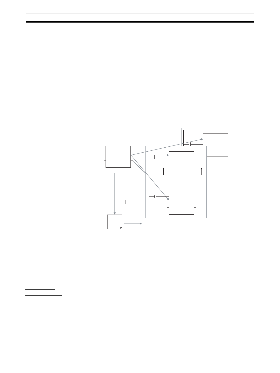
With the CX-Programmer, a single function block can be saved as a single file
and reused in other PLC programs, so standard processing functions can be
made into libraries.
Program 2
Copy of function block A
Function block A
Standard
program section
written with
variables
Define in advance.
Insert in
program.
Save function
block as a file.
Convert to
library function.
Function
block A
Reuse.
1-2-2 Advantages of Function Blocks
Function blocks allow complex programming units to be reused easily. Once
standard programming is created in a function block and saved in a file, it can
be reused just by placing the function block in a program and setting the
parameters for the function block’s I/O. The ability to reuse existing function
blocks will save significant time when creating/debugging programs, reduce
coding errors, and make the program easier to understand.
Program 1
Copy of function block A
Input Output
Variable Variable
Set
Copy of function block A
Input Output
Variable Variable
To another PLC program
Set
Variable
Output
Structured
Programming
Easy-to-read “Black Box”
Design
Use One Function Block
for Multiple Processes
Structured programs created with function blocks have better design quality
and require less development time.
The I/O operands are displayed as variable names in the program, so the program is like a “black box” when entering or reading the program and no extra
time is wasted trying to understand the internal algorithm.
Many different processes can be created easily from a single function block by
using the parameters in the standard process as input variables (such as
timer SVs, control constants, speed settings, and travel distances).
7
Page 23
Function Blocks Section 1-2
Reduce Coding Errors Coding mistakes can be reduced because blocks that have already been
debugged can be reused.
Data Protection The variables in the function block cannot be accessed directly from the out-
side, so the data can be protected. (Data cannot be changed unintentionally.)
Improved Reusability with
Variable Programming
The function block’s I/O is entered as variables, so it isn’t necessary to change
data addresses in a block when reusing it.
Creating Libraries Processes that are independent and reusable (such as processes for individ-
ual steps, machinery, equipment, or control systems) can be saved as function block definitions and converted to library functions.
The function blocks are created with variable names that are not tied to actual
addresses, so new programs can be developed easily just by reading the definitions from the file and placing them in a new program.
Compatible with
Mathematical expressions can be entered in structured text (ST) language.
Multiple Languages
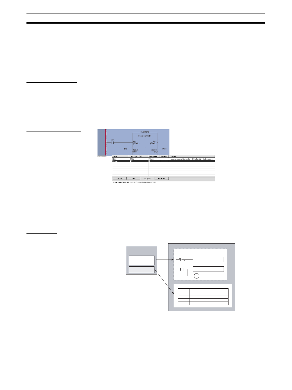
1-2-3 Function Block Structure
Function Block
Definitions
Function blocks consist of function block definitions that are created in
advance and function block instances that are inserted in the program.
Function block definitions are the programs contained in function blocks. Each
function block definition contains the algorithm and variable definitions, as
shown in the following diagram.
Function Block Definition
Example: CLOCK PULSE
Algorithm
Variable definitions
Example: CLOCK PULSE
1. Algorithm
tim_b
tim_a
2. Variable Definitions
Usage
Internal
Internal
Input
Input
TIMX tim_a OFF_TIME
TIMX tim_b ON_TIME
Name
tim_a TIMER
tim_b TIMER
ON_TIME INT
OFF_TIME INT
ENO
Type
1. Algorithm
Standardized programming is written with variable names rather than real I/O
memory addresses. In the CX-Programmer, algorithms can be written in
either ladder programming or structured text.
8
Page 24
Function Blocks Section 1-2
2. Variable Definitions
The variable table lists each variable’s usage (input, output, or internal) and
properties (data type, etc.). For details, refer to 1-3 Variables.
Number of Function Block
Definitions
The maximum number of function block definitions that can be created for one
CPU Unit is either 128 or 1,024 depending on the CPU Unit model.
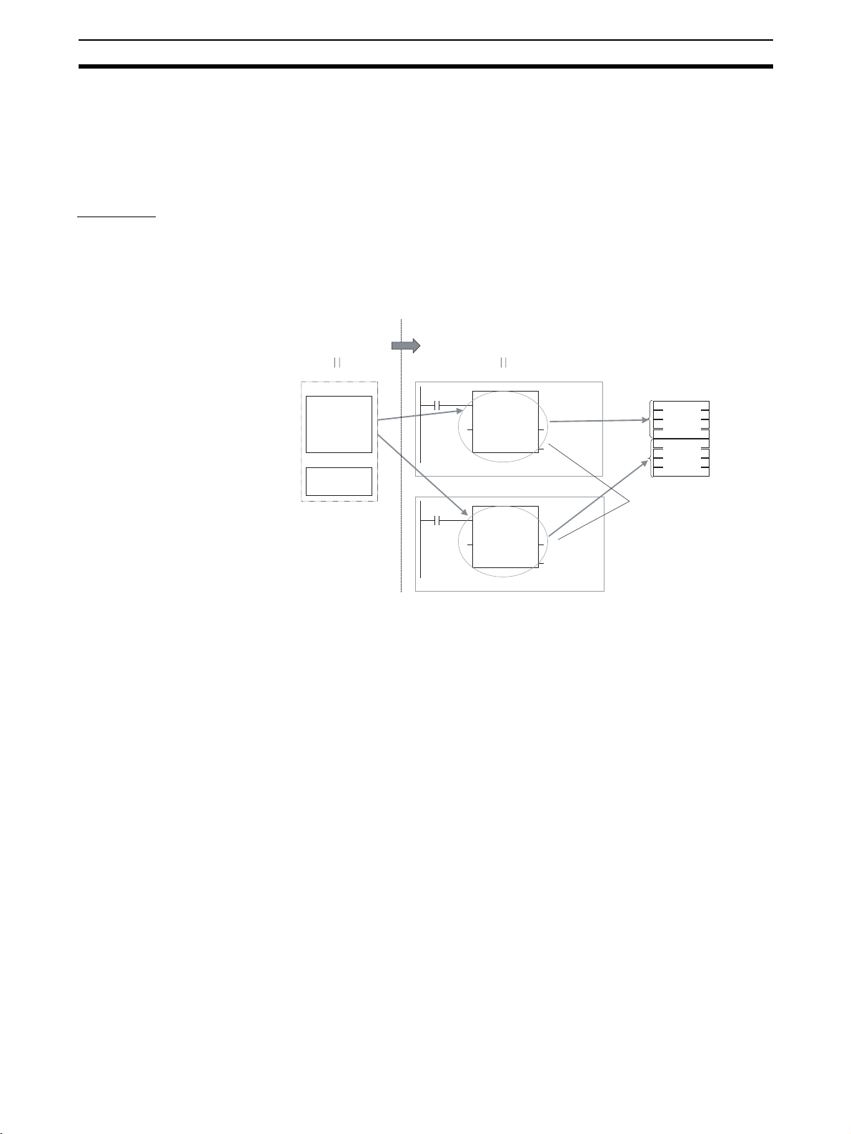
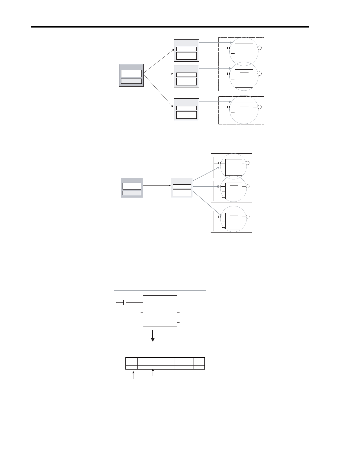
Instances To use an actual function block definition in a program, create a copy of the
function block diagram and insert it in the program. Each function block definition that is inserted in the program is called an “instance” or “function block
instance.” Each instance is assigned an identifier called an “instance name.”
By generating instances, a single function block definition can be used to process different I/O data with the same function.
Not yet in program
and memory not yet
allocated
(abstract).
Function Block Definition FB1
1. Algorithm
Standard
program unit
with variable
names a, b, c,
etc.
2. Parameters
Table defining usage
and properties of
variables a, b, c, etc.
Insert in
program.
Insert in
program.
Block instance in program with memory
allocated. (object)
Program
Instance FB1_1 of function block definition FB1
Input
data
Instance FB1_2 of function block definition FB1
Input
data
Instance
ab
ab
c
Output data
Output data
c
Output data
Output data
Automatic
allocation
Automatic
allocation
Memory
used
Memory
for FB1_1
Memory
for FB1_2
Different I/O data
can be processed
with the same
function.
Note Instances are managed by names. More than one instance with the same
name can also be inserted in the program. If two or more instances have the
same name, they will use the same internal variables. Instances with different
names will have different internal variables.
For example, consider multiple function blocks that use a timer as an internal
variable. In this case all instances will have to be given different names. If
more than one instance uses the same name, the same timer would be used
in multiple locations, resulting in duplicated use of the timer.
If, however, internal variables are not used or they are used only temporarily
and initialized the next time an instance is executed, the same instance name
can be used to save memory.
9
Page 25
Function Blocks Section 1-2
instance_A
Function Block Definition
TIMER_FB
Variable Definitions
Internal variable: WORK_NUM
TIMER_FB
Use same internal variables.
instance_A
TIMER_FB
instance_B
TIMER_FB
Use different internal variables.
Number of Instances Multiple instances can be created from a single function block definition. Up to
either 256 or 2,048 instances can be created for a single CPU Unit depending
on the CPU Unit model. The allowed number of instances is not related to the
number of function block definitions and the number of tasks in which the
instances are inserted.
Parameters Each time an instance is created, set the real I/O memory addresses or con-
stants for I/O variables used to pass input data values to instances and obtain
output data values from instances. These addresses and constants are called
parameters.
Instance of Function Block Definition A
Input 0.00
Input 3.00
Set the constants or
input source addresses
from which to pass data.
ab
c
Output 2.00
Set the constant or
output destination
address to which to pass
data.
10
Here, it is not the input source address itself, but the contents at the input
address in the form and size specified by the variable data type that is passed
to the function block. In a similar fashion, it is not the output destination
address itself, but the contents for the output address in the form and size
specified by the variable data type that is passed from the function block.
Page 26
Function Blocks Section 1-2
Even if an input source address (i.e., an input parameter) or an output destination address (i.e., an output parameter) is a word address, the data that is
passed will be the data in the form and size specified by the variable data type
starting from the specified word address.
Program
Instance of Function Block Definition A
Input D100
Input D200
Examples:
If m is type WORD, one word of data from D100 will be passed to the
variable.
If n is type DWORD, two words of data from D200 and D201 will be
passed to the variable.
If k is type LWORD, four words of data from the variable will be passed
to the D300 to D303.
mk
n
Output D300
Note (1) Only addresses in the following areas can be used as parameters: CIO
Area, Auxiliary Area, DM Area, EM Area (banks 0 to C), Holding Area,
and Work Area.
The following cannot be used: Index and Data Registers (both direct and
indirect specifications) and indirect addresses to the DM Area and EM
Area (both in binary and BCD mode).
(2) Local and global symbols in the user program can also be specified as
parameters. To do so, however, the data size of the local or global symbol
must be the same as the data size of the function block variable.
(3) When an instance is executed, input values are passed from parameters
to input variables before the algorithm is processed. Output values are
passed from output variables to parameters just after processing the algorithm. If it is necessary to read or write a value within the execution cycle of the algorithm, do not pass the value to or from a parameter. Assign
the value to an internal variable and use an AT setting (specified addresses).
!Caution If an address is specified in an input parameter, the values in the address are
passed to the input variable. The actual address data itself cannot be passed.
!Caution Parameters cannot be used to read or write values within the execution cycle
of the algorithm. Use an internal variable with an AT setting (specified
addresses). Alternatively, reference a global symbol as an external variable.
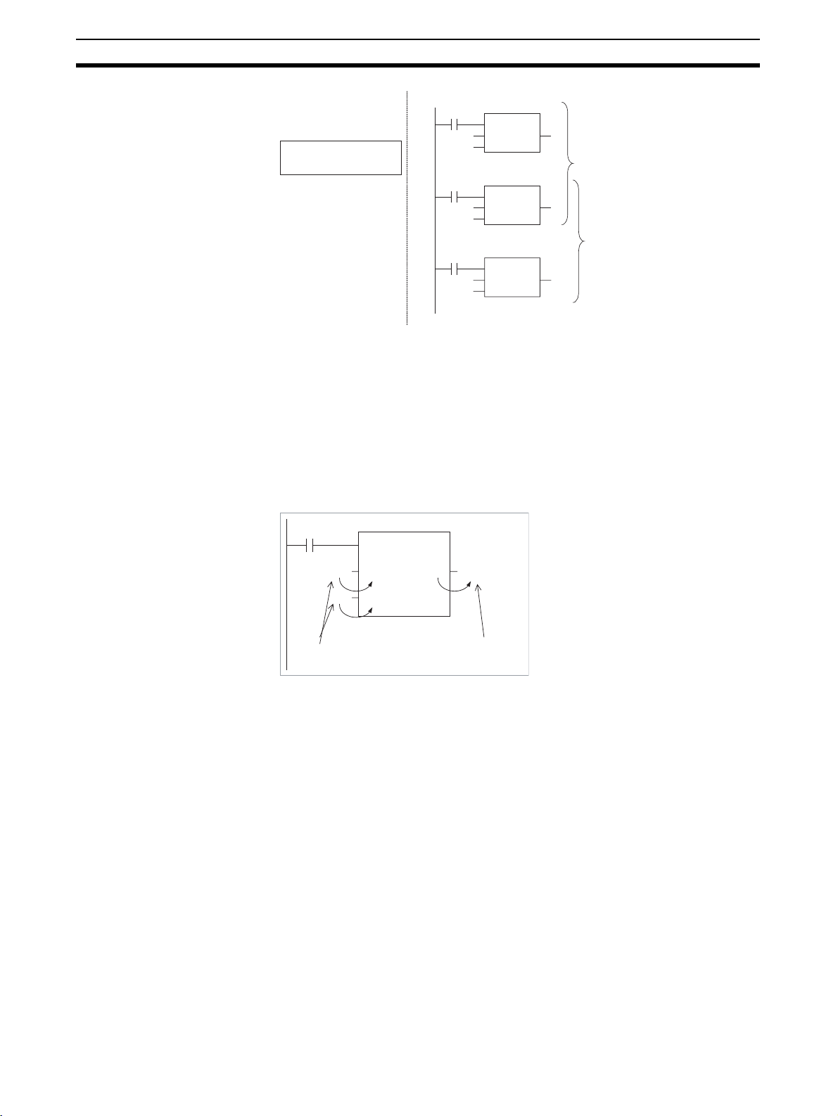
■ Reference Information
A variety of processes can be created easily from a single function block by
using parameter-like elements (such as fixed values) as input variables and
changing the values passed to the input variables for each instance.
Example: Creating 3 Instances from 1 Function Block Definition
11
Page 27
Function Blocks Section 1-2
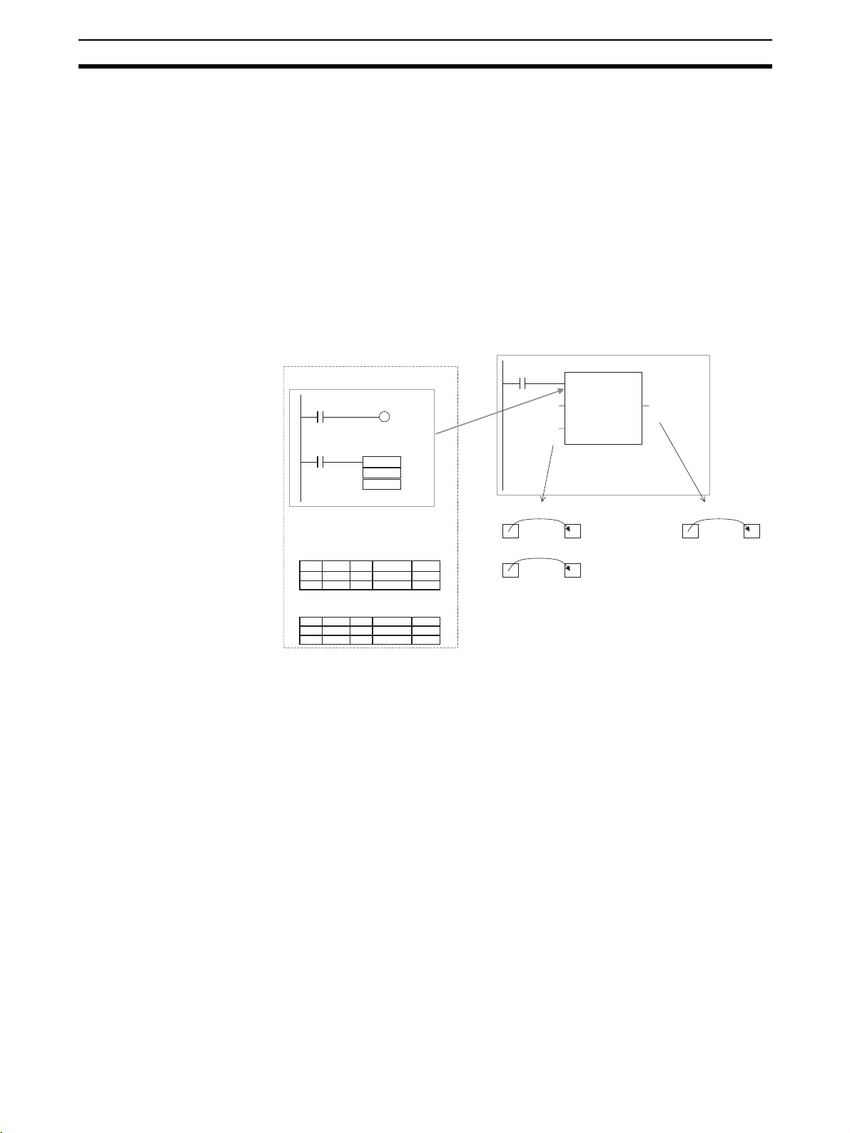
Cyclic task 0
Instance
CASCADE_01
Algorithm
Internal and I/O
Function Block Definition
Example: CONTROL
Algorithm
Variables
Example:
There are 3 FB
instances and each
has its own I/O and
internal variables.
variables
Instance
CASCADE_02
Algorithm
Internal and I/O
variables
Instance
CASCADE_03
Algorithm
Internal and I/O
variables
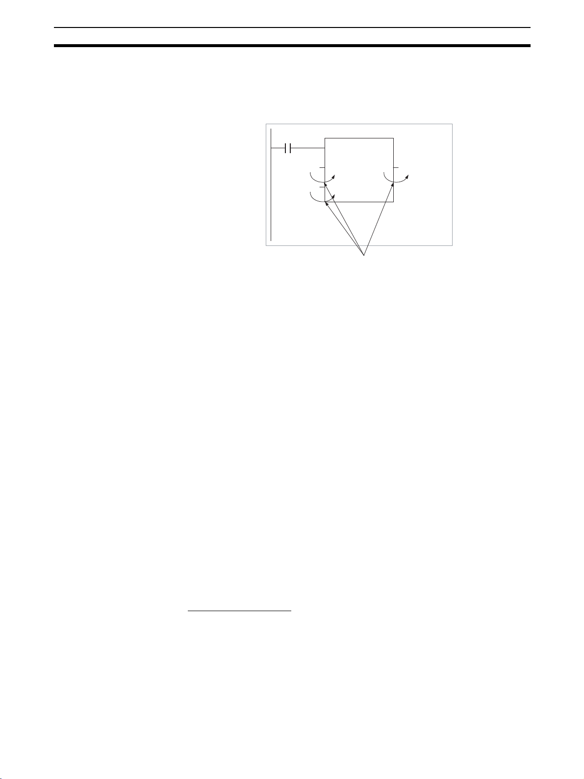
If internal variables are not used, if processing will not be affected, or if the
internal variables are used in other locations, the same instance name can be
used at multiple locations in the program.
Cyclic task 0
P_On
&100
&130
P_On
&150
Function block definition
Example: CONTROL
Algorithm
Variables
The same instance can be
used at multiple locations.
Instance
CASCADE
Algorithm
Internal and I/O
variables
P_On
&20
&10
P_On
&15
&10
Cyclic task 1
P_On
&7
&8
CASCADE
CONTROL
EN ENO
PARA_1
PARA_2
CASCADE
CONTROL
EN ENO
&50
PARA_1
PARA_2
CASCADE_01
CONTROL
EN ENO
ON_TIME
OFF_TIME
CASCADE_02
CONTROL
EN ENO
ON_TIME
OFF_TIME
CASCADE_03
CONTROL
EN ENO
ON_TIME
OFF_TIME
1.0
1.1
1.2
1.0
1.1
Cyclic task 1
P_On
&100
&200
CASCADE
EN ENO
PARA_1
PARA_2
CONTROL
1.2
Some precautions are required when using the same memory area. For
example, if the same instance containing a timer instruction is used in more
than one program location, the same timer number will be used causing coil
duplication, and the timer will not function properly if both instructions are executed.
Registration of Instances Each instance name is registered in the global symbol table as a file name.
Program
Instance (sample) of function block definition A
ab
c
The instance is registered in the
global symbol table with the instance
name as the symbol name.
Name
Data type
sample FB [FunctionBlock1] N/A[Auto]
Instance name
Address/
value
The function block definition
name is registered after FB in
square parentheses [ ].
12
Page 28
Variables Section 1-3
1-3 Variables
1-3-1 Introduction
In a function block, the addresses (see note) are not entered as real I/O memory addresses, they are all entered as variable names. Each time an instance
is created, the actual addresses used by the variable are allocated automatically in the specified I/O memory areas by the CX-Programmer. Consequently, it isn’t necessary for the user to know the real I/O memory addresses
used in the function block, just as it isn’t necessary to know the actual memory allocations in a computer. A function block differs from a subroutine in this
respect, i.e., the function block uses variables and the addresses are like
“black boxes.”
Example:
Insert in
program.
Program
Input 0.00
Input 3.00
Instance of function block definition A
ab
c
Output 2.00
Function block definition A
Standard program section with
variable names a, b, c, etc.
a
c
b
MOV
Specify inputs and outputs
at the same time.
Table indicating usage and
prpperties of variables a, b, c, etc.
Usage: Inputs
Prpperties:
Name Type AT Initial Value Retained
a BOOL
c
BOOL
Usage: Outputs
Prpperties:
Name Type AT Initial Value
BOOL
b
Retained
Note Constants are not registered as variables. Enter constants directly in instruc-
tion operands.
• Ladder programming language: Enter hexadecimal numerical values
after the # and decimal values after the &.
• Structured text (ST language): Enter hexadecimal numerical values after 16# and enter decimal numerical values as is.
Exception: Enter directly or indirectly specified addresses for Index Registers
IR0 to IR15 and Data Registers DR0 to DR15 directly into the instruction
operand.
1-3-2 Variable Usage and Properties
Status of 0.00 (1 or 0) is
passed to a.
0.00 a
11
Status of 3.00 (1 or 0) is
passed to c.
3.00
00
c
The system automatically allocates the
addresses used by variables a, b, and c. For
example, when W100 to W120 is set as the
system’s non-retained memory area, bit
addresses such as a = W10000, b = W10001,
and c = W10002 will be allocated.
Status of b (1 or 0) is
passed to 2.00.
b
2.00
11
Variable Usage The following variable types (usages) are supported.
Internals: Internal variables are used only within an instance. They cannot
be used pass data directly to or from I/O parameters.
Inputs: Input variables can input data from input parameters outside of
the instance. The default input variable is an EN (Enable) variable, which passes input condition data.
13
Page 29

Variables Section 1-3
Outputs: Output variables can output data to output parameters outside of
the instance. The default output variable is an ENO (Enable Out)
variable, which passes the instance’s execution status.
Externals: External variables are either system-defined variables registered
in advance with the CX-Programmer, such as the Condition Flags
and some Auxiliary Area bits, or user-defined global symbols for
use within instances.
For details on variable usage, refer to the section on Variable Type (Usage)
under Variable Definitions in 2-1-2 Function Block Elements.
The following table shows the number of variables that can be used and the
kind of variable that is created by default for each of the variable usages.
1-3-3 Variable Properties
Variables have the following properties.
Variable Name The variable name is used to identify the variable in the function block. It
doesn’t matter if the same name is used in other function blocks.
Note The variable name can be up to 30,000 characters long, but must not begin
with a number. Also, the name cannot contain two underscore characters in a
row. The character string cannot be the same as that of a an index register
such as in IR0 to IR15. For details on other restrictions, refer to Var i a bl e D e f i-
nitions in 2-1-2 Function Block Elements.
Data Type Select one of the following data types for the variable:
BOOL, INT, UINT, DINT, UDINT, LINT, ULINT, WORD, DWORD, LWORD,
REAL, LREAL, TIMER, COUNTER
For details on variable data types, refer to Variable Definitions in 2-1-2 Func-
tion Block Elements.
AT Settings (Allocation to
an Actual Addresses)
Array Settings A variable can be treated as a single array of data with the same properties.
It is possible to set a variable to a particular I/O memory address rather than
having it allocated automatically by the system. To specify a particular
address, the user can input the desired I/O memory address in this property.
This property can be set for internal variables only. Even if a specific address
is set, the variable name must still be used in the algorithm.
Refer to Variable Definitions in 2-1-2 Function Block Elements for details on
AT settings and 2-4-3 AT Settings for Internal Variables for details on using AT
settings.
To convert a variable to an array, specify that it is an array and specify the
maximum number of elements.
This property can be set for internal variables only. Only one-dimensional
arrays are supported by the CX-Programmer Ver. 5.0.
• Setting Procedure
Click the Advanced Button, select the Array Variable option, and input the
maximum number of elements.
• When entering an array variable name in the algorithm in a function block
definition, enter the array index number in square brackets after the variable number.
For details on array settings, refer to Variable Definitions in
Elements
.
2-1-2 Function Block
Initial Value This is the initial value set in a variable before the instance is executed for the
first time. Afterwards, the value may be changed as the instance is executed.
14
Page 30

Variables Section 1-3
For example, set a boolean (BOOL) variable (bit) to either 1 (TRUE) or 0
(FALSE). Set a WORD variable to a value between 0 and 65,535 (between
0000 and FFFF hex).
If an initial value is not set, the variable will be set to 0. For example, a boolean variable would be 0 (FALSE) and a WORD variable would be 0000 hex.
Retain Select the Retain Option if you want a variable’s data to be retained when the
PLC is turned ON again and when the PLC starts operating.
• Setting Procedure
Select the Retain Option.
1-3-4 Variable Properties and Variable Usage
The following table shows which properties must be set, can be set, and cannot be set, based on the variable usage.
Property Variable usage
Internals Inputs Outputs
Name Must be set. Must be set. Must be set.
Data Type Must be set. Must be set. Must be set.
AT (specified address) Can be set. Cannot be set. Cannot be set.
Initial Value Can be set. Can be set.
(See note.)
Retained Can be set. Can be set.
(See note.)
Can be set.
Can be set.
Note Inputs can be set as initial values, but the value of the actual input parameter
will be given priority.
1-3-5 Internal Allocation of Variable Addresses
When an instance is created from a function block definition, the CX-Programmer internally allocates addresses to the variables. Addresses are allocated
to all of the variables registered in the function block definition except for variables that have been assigned actual addresses with the AT Settings prop-
erty.
Program
Instance of function block definition A
Input 0.00
Note: Variable c is an internal
a
variable, so it is not displayed.
Usage: Inputs
Properties:
Name Type AT Initial Value
a BOOL
Usage: Outputs
Properties:
Name Type AT
b
BOOL
t
TIMER
Usage: Internals
Properties:
Name Type Initial Value
c
BOOL
AT
2000.00
Initial Value
b
Output 2.00
t
Output 5.00
Retained
Retained
YES
Retained
Non-retained area
Starting address
Retained area
Starting address
Timer area
Starting address
Counter area
Automatic allocation of
addresses by system
Manual allocation of address to
variable in FB by AT Settings option.
FB instance areas
Starting
address
Example
2000.00
15 0
CIO, H, W,
D, or E Area
15 0
H, D, or E
Area
T Area
C Area
Size (words)
Size (words)
Size (Completion
Flags)
Size (Completion
Flags)
Setting Internal Allocation
Areas for Variables
The user sets the function block instance areas in which addresses are allocated internally by the system. The variables are allocated automatically by
the system to the appropriate instance area set by the user.
15
Page 31

Converting Function Block Definitions to Library Files Section 1-4
Setting Procedure
Select Function Block Memory - Function Block Memory Allocation from
the PLC Menu. Set the areas in the Function Block Memory Allocation Dialog
Box.
Function Block Instance Areas
FB Instance
Area
Start Address End Address Size
Non Retain H512 H1407 896 CIO, WR, HR, DM, EM
Retain H1408 H1535 128 HR, DM, EM
Timers T3072 T4095 1024 TIM
Counters C3072 C4095 1024 CNT
Default value Applicable memory
areas
Function Block Holding
Area Words (H512 to
H1535)
The Function Block Holding Area words are allocated from H512 to H1535.
These words are different to the standard Holding Area used for programs
(H000 to H511) and are used only for the function block instance area (internally allocated variable area). These words cannot be specified as instruction
operands. They are displayed in red if input when a function block is not being
created. Although the words can be input when creating a function block, an
error will occur when the program is checked. If this area is specified not to be
retained in the Function Block Memory Allocation Dialog Box, turn the power
ON/OFF or clear the area without retaining the values when starting operation.
1-4 Converting Function Block Definitions to Library Files
A function block definition created using the CX-Programmer can be stored as
a single file known as a function block definition file with filename extension
*.cxf. These files can be reused in other projects (PLCs).
Project Project
Function block definition
Example: CLOCK_PULSE
1. Algorithm
tim_b
TIMX tim_a OFF_TIME
tim_a
TIMX tim_b ON_TIME
ENO
2. Variable Definitions
Usage
Name
Internal
tim_a TIMER
tim_b TIMER
Internal
ON_TIME INT
Input
OFF_TIME INT
Input
Save
Type
Function block
definition file (.cxf)
Read
Function block definition
Example: CLOCK_PULSE
1. Algorithm
tim_b
TIMX tim_a OFF_TIME
tim_a
TIMX tim_b ON_TIME
ENO
2. Variable Definitions
Usage
Name
Internal
Internal
Input
Input
tim_a TIMER
tim_b TIMER
ON_TIME INT
OFF_TIME INT
Type
16
Page 32

Usage Procedures Section 1-5
1-5 Usage Procedures
Once a function block definition has been created and an instance of the algorithm has been created, the instance is used by calling it when it is time to
execute it. Also, the function block definition that was created can be saved in
a file so that it can be reused in other projects (PLCs).
1-5-1 Creating Function Blocks and Executing Instances
The following procedure outlines the steps required to create and execute a
function block.
1,2,3... 1. First, create the function block definition including the algorithm and vari-
able definitions in ladder program or ST language. Alternatively, insert a
function block library file that has been prepared in advance.
Note (a) Create the algorithm entirely with variable names.
(b) When entering the algorithm in ladder programming language,
project files created with versions of CX-Programmer earlier than
Ver. 5.0 can be reused by reading the project file into the CX-Programmer Ver. 5.0 and copying and pasting useful parts.
2. When creating the program, insert copies of the completed function block
definition. This step creates instances of the function block.
3. Enter an instance name for each instance.
4. Set the variables’ input source addresses and/or constants and output
destination addresses and/or constants as the parameters to pass data for
each instance.
5. Select the created instance, select Function Block Memory - Function
Block Memory Allocation from the PLC Menu, and set the internal data
area for each type of variable.
6. Transfer the program to the CPU Unit.
7. Start program execution in the CPU Unit and the instance will be called and
executed if their input conditions are ON.
The instance is
Function block definition A
1. Algorithm
Standard
program section
with variable
names a, b, c,
etc.
2. Variables
Table defining usage
and properties of
variables a, b, c, etc.
Insert in
program.
Program
Input
condition
executed if the input
condition is established.
Instance of function block definition A
Input 0.00
a b
4. Specify the input source and
output destination addresses.
3. Input instance name
5. The system automatically allocates
the addresses used by these
variables. Set the data area area in
which these addresses are allocated.
Output 2.00
c
Output 3.00
17
Page 33

Usage Procedures Section 1-5
1-5-2 Reusing Function Blocks
Use the following procedure to save a function block definition as a file and
use it in a program for another PLCs.
1,2,3... 1. Select the function block that you want to save and save it as a function
block definition file (*.cxf).
2. Open the other PLC’s project and open/read the function block definition
file (*.cxf) that was saved.
3. Insert the function block definition in the program when creating the new
program.
Function block definition A
Read and
insert.
Program
Input
condition
Input 1.00
Instance of function block definition A
c
Output 5.00
Output 6.00
ab
1. Algorithm
Standard
program section
with variable
names a, b, c,
etc.
2. Variables
Table defining usage
and properties of
variables a, b, c, etc.
Save
Function
block
definition
A
Function block
definition file (*.cxf)
Note In the CX-Programmer Ver. 5.0, each function block definition can be com-
piled and checked as a program. We recommend compiling to perform a program check on each function block definition file before saving or reusing the
file.
18
Page 34

SECTION 2
Specifications
This section provides specifications for reference when using function blocks, including specifications on function blocks,
instances, and compatible PLCs, as well as usage precautions and guidelines.
2-1 Function Block Specifications . . . . . . . . . . . . . . . . . . . . . . . . . . . . . . . . . . . . 21
2-1-1 Function Block Specifications . . . . . . . . . . . . . . . . . . . . . . . . . . . . . 21
2-1-2 Function Block Elements . . . . . . . . . . . . . . . . . . . . . . . . . . . . . . . . . 21
2-2 Instance Specifications . . . . . . . . . . . . . . . . . . . . . . . . . . . . . . . . . . . . . . . . . . 30
2-2-1 Composition of an Instance . . . . . . . . . . . . . . . . . . . . . . . . . . . . . . . 30
2-2-2 Parameter Specifications. . . . . . . . . . . . . . . . . . . . . . . . . . . . . . . . . . 34
2-2-3 Operating Specifications. . . . . . . . . . . . . . . . . . . . . . . . . . . . . . . . . . 35
2-3 Restrictions on Function Blocks . . . . . . . . . . . . . . . . . . . . . . . . . . . . . . . . . . . 37
2-4 Function Block Applications Guidelines . . . . . . . . . . . . . . . . . . . . . . . . . . . . 42
2-4-1 Deciding on Variable Data Types . . . . . . . . . . . . . . . . . . . . . . . . . . . 42
2-4-2 Determining Variable Types (Inputs, Outputs, Externals, and Internals) 42
2-4-3 AT Settings for Internal Variables. . . . . . . . . . . . . . . . . . . . . . . . . . . 43
2-4-4 Array Settings for Internal Variables . . . . . . . . . . . . . . . . . . . . . . . . 44
2-4-5 Specifying Addresses Allocated to Special I/O Units . . . . . . . . . . . 45
2-4-6 Using Index Registers. . . . . . . . . . . . . . . . . . . . . . . . . . . . . . . . . . . . 46
2-5 Precautions for Instructions with Operands Specifying the First or Last
of Multiple Words . . . . . . . . . . . . . . . . . . . . . . . . . . . . . . . . . . . . . . . . . . . . . . 49
2-6 Instruction Support and Operand Restrictions . . . . . . . . . . . . . . . . . . . . . . . . 52
2-6-1 Sequence Input Instructions . . . . . . . . . . . . . . . . . . . . . . . . . . . . . . . 53
2-6-2 Sequence Output Instructions. . . . . . . . . . . . . . . . . . . . . . . . . . . . . . 55
2-6-3 Sequence Control Instructions . . . . . . . . . . . . . . . . . . . . . . . . . . . . . 56
2-6-4 Timer and Counter Instructions . . . . . . . . . . . . . . . . . . . . . . . . . . . . 57
2-6-5 Comparison Instructions. . . . . . . . . . . . . . . . . . . . . . . . . . . . . . . . . . 60
2-6-6 Data Movement Instructions. . . . . . . . . . . . . . . . . . . . . . . . . . . . . . . 62
2-6-7 Data Shift Instructions . . . . . . . . . . . . . . . . . . . . . . . . . . . . . . . . . . . 64
2-6-8 Increment/Decrement Instructions . . . . . . . . . . . . . . . . . . . . . . . . . . 67
2-6-9 Symbol Math Instructions. . . . . . . . . . . . . . . . . . . . . . . . . . . . . . . . . 67
2-6-10 Conversion Instructions . . . . . . . . . . . . . . . . . . . . . . . . . . . . . . . . . . 72
2-6-11 Logic Instructions . . . . . . . . . . . . . . . . . . . . . . . . . . . . . . . . . . . . . . . 74
2-6-12 Special Math Instructions . . . . . . . . . . . . . . . . . . . . . . . . . . . . . . . . . 76
2-6-13 Floating-point Math Instructions . . . . . . . . . . . . . . . . . . . . . . . . . . . 76
2-6-14 Double-precision Floating-point Instructions. . . . . . . . . . . . . . . . . . 80
2-6-15 Table Data Processing Instructions. . . . . . . . . . . . . . . . . . . . . . . . . . 82
2-6-16 Data Control Instructions . . . . . . . . . . . . . . . . . . . . . . . . . . . . . . . . . 85
2-6-17 Subroutine Instructions. . . . . . . . . . . . . . . . . . . . . . . . . . . . . . . . . . . 86
2-6-18 Interrupt Control Instructions . . . . . . . . . . . . . . . . . . . . . . . . . . . . . . 87
2-6-19 High-speed Counter and Pulse Output Instructions
(CJ1M-CPU21/22/23 Only) . . . . . . . . . . . . . . . . . . . . . . . . . . . . . . . 88
19
Page 35

2-6-20 Step Instructions . . . . . . . . . . . . . . . . . . . . . . . . . . . . . . . . . . . . . . . . 89
2-6-21 Basic I/O Unit Instructions . . . . . . . . . . . . . . . . . . . . . . . . . . . . . . . . 89
2-6-22 Serial Communications Instructions . . . . . . . . . . . . . . . . . . . . . . . . . 91
2-6-23 Network Instructions . . . . . . . . . . . . . . . . . . . . . . . . . . . . . . . . . . . . . 93
2-6-24 File Memory Instructions . . . . . . . . . . . . . . . . . . . . . . . . . . . . . . . . . 95
2-6-25 Display Instructions. . . . . . . . . . . . . . . . . . . . . . . . . . . . . . . . . . . . . . 95
2-6-26 Clock Instructions . . . . . . . . . . . . . . . . . . . . . . . . . . . . . . . . . . . . . . . 96
2-6-27 Debugging Instructions . . . . . . . . . . . . . . . . . . . . . . . . . . . . . . . . . . . 97
2-6-28 Failure Diagnosis Instructions. . . . . . . . . . . . . . . . . . . . . . . . . . . . . . 98
2-6-29 Other Instructions . . . . . . . . . . . . . . . . . . . . . . . . . . . . . . . . . . . . . . . 98
2-6-30 Block Programming Instructions . . . . . . . . . . . . . . . . . . . . . . . . . . . 99
2-6-31 Text String Processing Instructions. . . . . . . . . . . . . . . . . . . . . . . . . . 101
2-6-32 Task Control Instructions . . . . . . . . . . . . . . . . . . . . . . . . . . . . . . . . . 103
2-6-33 Model Conversion Instructions . . . . . . . . . . . . . . . . . . . . . . . . . . . . . 103
2-6-34 Special Instructions for Function Blocks . . . . . . . . . . . . . . . . . . . . . 104
2-7 CPU Unit Function Block Specifications . . . . . . . . . . . . . . . . . . . . . . . . . . . . 104
2-7-1 Specifications . . . . . . . . . . . . . . . . . . . . . . . . . . . . . . . . . . . . . . . . . . 104
2-7-2 Operation of Timer Instructions . . . . . . . . . . . . . . . . . . . . . . . . . . . . 107
2-8 Number of Function Block Program Steps and Instance Execution Time . . . 108
2-8-1 Number of Function Block Program Steps
(CPU Units with Unit Version 3.0 or Later) . . . . . . . . . . . . . . . . . . . 108
2-8-2 Function Block Instance Execution Time
(CPU Units with Unit Version 3.0 or Later) . . . . . . . . . . . . . . . . . . . 109
20
Page 36

Function Block Specifications Section 2-1
2-1 Function Block Specifications
2-1-1 Function Block Specifications
Item Description
Number of function block definitions CS1-H/CJ1-H CPU Units:
• Suffix -CPU44H/45H/64H/65H/66H/67H:
1,024 max. per CPU Unit
• Suffix -CPU42H/43H/63H: 128 max. per CPU
Unit
CJ1M CPU Units:
• CJ1M-CPU11/12/13/21/22/23: 128 max. per
CPU Unit
Number of instances CS1-H/CJ1-H CPU Units:
• Suffix -CPU44H/45H/64H/65H/66H/67H:
2,048 max. per CPU Unit
• Suffix -CPU42H/43H/63H: 256 max. per CPU
Unit
CJ1M CPU Units:
CJ1M-CPU11/12/13/21/22/23: 256 max. per
CPU Unit
Number of instance nesting levels Nesting is not supported.
Number of I/O variables 64 variables max. per function block definition
2-1-2 Function Block Elements
The following table shows the items that must be entered by the user when
defining function blocks.
Item Description
Function block
definition name
Language The programming language used in the function block defini-
Variable definitions Variable settings, such as operands and return values,
Algorithm Enter the programming logic in ladder or structured text.
Comment Function blocks can have comments.
Function Block
Definition Name
Each function block definition has a name. The names can be up to 64 characters long and there are no prohibited characters. The default function block
name is FunctionBlock@, where @ is a serial number.
CLOCK PULSE
EN ENO
(BOOL) (BOOL)
ON_TIME
(INT)
OFF_TIME
(INT)
The name of the function block definition
tion. Select ladder programming or structured text
required when the function block is executed
• Type (usage) of the variable
• Name of the variable
• Data type of the variable
• Initial value of the variable
• Enter the programming logic using variables.
• Input constants directly without registering in variables.
Function block definition name
21
Page 37

Function Block Specifications Section 2-1
Language Select either ladder programming language or structured text (ST language).
For details refer to Appendix B Structured Text (ST Language) Specifications.
Variable Definitions Define the operands and variables used in the function block definition.
Variable Names • Variable names can be up to 30,000 characters long.
• Variables name cannot contain spaces or any of the following characters:
!“ #$%&‘()=-~^\|‘@{[+;*:}]<,>.?/
• Variable names cannot start with a number (0 to 9).
• Variable names cannot contain two underscore characters in a row.
•
The following characters cannot be used to indicate addresses in I/O
memory.
A, W, H (or HR), D (or DM), E (or EM), T (or TIM), C (or CNT) followed
by the numeric value (word address)
Variable Notation
CLOCK PULSE
EN
ENO
(BOOL) (BOOL)
ON_TIME
(INT)
OFF_TIME
(INT)
Input variables
Output variables
Variable table
Usage
Name
tim_a TIMER
Internal
Internal
tim_b TIMER
ON_TIME INT
Input
OFF_TIME INT
Input
tim_b
tim_a
Internal
variables
Type
TIMX tim_a OFF_TIME
TIMX tim_b OFF_TIME
ENO
Variable Type (Usage)
Item Variable type
Inputs Outputs Internals Externals
Definition Operands to the
instance
Status of value at next
execution
The value is not
passed on to the next
execution.
Display Displayed on the left
side of the instance.
Number allowed 64 max. per function
block (excluding EN)
AT setting No No Supported No
Array setting No No Supported No
Return values from the
instance
The value is passed on
to the next execution.
Displayed on the right
side of the instance.
64 max. per function
block (excluding ENO)
Variables used only
within instance
The value is passed on
to the next execution.
Not displayed. Not displayed.
Unlimited Unlimited
Global symbols registered as variables
beforehand with the
CX-Programmer or
user-defined global
symbols.
The value is not
passed on to the next
execution.
22
Page 38

Function Block Specifications Section 2-1
Item Variable type
Inputs Outputs Internals Externals
Retain setting No Supported Supported No
Variables created by
default
EN (Enable):
Receives an input con-
dition.
ENO (Enable Output):
Outputs the function
block’s execution status.
None Pre-defined symbols
registered in advance
as variables in the CXProgrammer, such as
Condition Flags and
some Auxiliary Area
bits.
Note For details on Externals, refer to Appendix C External Variables.
■ Input Variables
Input variables pass external operands to the instance. The input variables
are displayed on the left side of the instance.
The value of the input source (data contained in the specified parameter just
before the instance was called) will be passed to the input variable.
P_On
D0 D100
The value of the parameter specified as the input (value of D0)
is passed to the instance’s input variable (PV).
FB
EN
ENO
PV CV
1.0
Example
ADD_INT_DINT
0.0
EN ENO
D100
IN16 OUT32
D200
IN32
IN16 is an INT variable, so the content of D100 is used.
IN32 is a DINT variable, so the content of D200 and
D201 is used.
10.0
D1000
Algorithm (Body)
P_On
Variable table
Usage
tmp DINT
Internal
EN BOOL
Input
IN16 INT
Input
IN32 DINT
Input
ENO BOOL
Output
OUT32 DINT
Output
SIGN IN16 tmp
+L IN32 tmp OUT32
Name
Type
Note 1. The same name cannot be assigned to an input variable and output vari-
able. If it is necessary to have the same variable as an input variable and
output variable, register the variables with different names and transfer the
value of the input variable to the output variable in the function block with
an instruction such as MOV.
2. When the instance is executed, input values are passed from parameters
to input variables before the algorithm is processed. Consequently, values
cannot be read from parameters to input variables within the algorithm. If
it is necessary to read a value within the execution cycle of the algorithm,
do not pass the value from a parameter. Assign the value to an internal
variable and use an AT setting (specified addresses). Alternatively, reference the global symbol as external variables.
23
Page 39

Function Block Specifications Section 2-1
Initial Value
Initial values can be set for input variables, but the value of the input parameter will be enabled (the input parameter value will be set when the parameter
for input variable EN goes ON and the instance is executed).
Note The input parameter setting cannot be omitted when using the CX-
Programmer.
EN (Enable) Variable
When an input variable is created, the default input variable is the EN variable.
The instance will be executed when the parameter for input variable EN is ON.
■ Output Variables
Output variables pass return values from the instance to external applications.
The output variables are displayed on the right side of the instance.
After the instance is executed, the value of the output variable is passed to the
specified parameter.
P_On
D0 D100
The value of the output variable (CV) is passed to the parameter
specified as the output destination, which is D100 in this case.
FB
EN ENO
PV CV
1.0
Example
0.0
ADD_INT_DINT
EN ENO
D100
IN16 OUT32
D200
IN32
OUT32 is a DINT variable, so
the variable's value is passed
to D1000 and D1001.
10.0
D1000
Algorithm (Body)
EN
Variable table
Usage
tmp DINT
Internal
EN BOOL
Input
IN16 INT
Input
IN32 DINT
Input
ENO BOOL
Output
OUT32 DINT
Output
SIGN IN16 tmp
+L IN32 tmp OUT32
Name
Data type
Like internal variables, the values of output variables are retained until the
next time the instance is executed (i.e., when EN turns OFF, the value of the
output variable is retained).
Example:
In the following example, the value of output variable CV will be retained until
the next time the instance is executed.
Product A counter
CTD
CD Q
LD
PV CV
D150
24
Note 1. The same name cannot be assigned to an input variable and output vari-
able. If it is necessary to have the same variable as an input variable and
output variable, register the variables with different names and transfer the
value of the input variable to the output variable in the function block with
an instruction such as MOV.
Page 40

Function Block Specifications Section 2-1
2. When the instance is executed, output variables are passed to the corresponding parameters after the algorithm is processed. Consequently, values cannot be written from output variables to parameters within the
algorithm. If it is necessary to write a value within the execution cycle of the
algorithm, do not write the value to a parameter. Assign the value to an internal variable and use an AT setting (specified addresses).
Initial Value
An initial value can be set for an output variable that is not being retained, i.e.,
when the Retain Option is not selected. An initial value cannot be set for an
output variable if the Retain Option is selected.
The initial value will not be written to the output variable if the IOM Hold Bit
(A50012) is ON.
Auxiliary Area control bit Initial value
IOM Hold Bit (A50012) ON The initial value will not be set.
ENO (Enable Output) Variable
The ENO variable is created as the default output variable. The ENO output
variable will be turned ON when the instance is called. The user can change
this value. The ENO output variable can be used as a flag to check whether or
not instance execution has been completed normally.
■ Internal Variables
Internal variables are used within an instance. These variables are internal to
each instance. They cannot be referenced from outside of the instance and
are not displayed in the instance.
The values of internal variables are retained until the next time the instance is
executed (i.e., when EN turns OFF, the value of the internal variable is
retained). Consequently, even if instances of the same function block definition are executed with the same I/O parameters, the result will not necessarily
be the same.
Example:
The internal variable tim_a in instance Pulse_2sON_1sOFF is different from
internal variable tim_a in instance Pulse_4sON_1sOFF, so the instances cannot reference and will not affect each other’s tim_a value.
Variable table
Usage
Internal
Internal
Input
Input
Name
tim_a TIMER
tim_b TIMER
ON_TIME INT
OFF_TIME INT
Data type
P_On
&20
&10
P_On
&40
&10
Pulse_2sON_1sOFF
CLOCK PULSE
EN ENO
ON_TIME
OFF_TIME
Pulse_4sON_1sOFF
CLOCK PULSE
EN ENO
ON_TIME
OFF_TIME
1.0
1.1
25
Page 41

Function Block Specifications Section 2-1
Algorithm (Body)
0.0
ADD_INT_DINT
EN ENO
D100
IN16 OUT32
D200
IN32
Internal variable tmp
is not displayed.
Retain Data through Power Interruptions and Start of Operation
Internal variables retain the value from the last time that the instance was
called. In addition, the Retain Option can be selected so that an internal variable will also retains its value when the power is interrupted or operation
starts (the mode is switched from PROGRAM to RUN or MONITOR mode).
When the Retain Option is selected, the value of the variable is retained when
the power is interrupted or operation starts unless the CPU Unit does not
have a backup battery. If the CPU Unit does not have a good battery, the value
will be unstable.
Variables Condition Status
Variables set to Retain Start of operation Retained
10.0
D1000
EN
SIGN IN16 tmp
+L IN32 tmp OUT32
Variable table
Internal
Input
Input
Input
Output
Output
Power ON Retained
Name
tmp DINT
EN BOOL
IN16 INT
IN32 DINT
ENO BOOL
OUT32 DINT
Type
When the Retain Option is not selected, the value of the variable will not be
held when the power is interrupted or operation starts. Even variables not set
to be retained, however, can be held at the start of operation by turning ON
the IOM Hold Bit (A50012) and can be held during power interruptions by setting the PLC Setup, as shown in the following table.
Variables Condition IOM Hold Bit (A50012) setting
OFF ON
IOM Hold Bit Status at Startup
IOM Hold Bit Status at Startup
(PLC Setup) selected
Variables not
set to Retain
Start of operation Not retained Retained Retained
Power ON Not retained Retained Not retained
Note The IOM Hold Bit (A50012) is supported for compatibility with previous mod-
els. To hold the values of variables in function blocks, however, use the Retain
Option and not the IOM Hold Bit.
Initial Value
An initial value can be set for an internal variable that is not being retained
(i.e., when the Retain Option not selected). An initial value cannot be set for
an internal variable if the Retain Option is selected.
Internal variables that are not being retained will be initialized to 0.
The initial value will not be written to the internal variable if the IOM Hold Bit
(A50012) is ON
Auxiliary Area control bit Initial value
IOM Hold Bit (A50012) ON The initial value will not be set.
.
OFF The initial value will be set.
(PLC Setup) not selected
26
■ External Variables
External variables are either system-defined variables that have been registered in CX-Programmer before hand, or variables that externally reference
user-defined variables in the global symbol table.
Page 42

Function Block Specifications Section 2-1
• For details on system-defined variables, refer to Appendix C External
Var iable s .
• To reference user-defined variables in the global symbol table, the variables must be registered in the global symbol table using the same variable name and data type as the external variable.
Variable Properties Variable Name
The variable name is used to identify the variable in the function block. The
name can be up to 30,000 characters long. The same name can be used in
other function blocks.
Note A variable name must be input for variables, even ones with AT settings (spec-
ified address).
Data Type
Any of the following types may be used.
Data type Content Size Inputs Outputs Internals
BOOL Bit data 1 bit OK OK OK
INT Integer 16 bits OK OK OK
UNIT Unsigned integer 16 bits OK OK OK
DINT Double integer 32 bits OK OK OK
UDINT Unsigned double integer 32 bits OK OK OK
LINT Long (4-word) integer 64 bits OK OK OK
ULINT Unsigned long (4-word) integer 64 bits OK OK OK
WORD 16-bit data 16 bits OK OK OK
DWORD 32-bit data 32 bits OK OK OK
LWORD 64-bit data 64 bits OK OK OK
REAL Real number 32 bits OK OK OK
LREAL Long real number 64 bits OK OK OK
TIMER Timer (See note 1.) Flag: 1 bit
PV: 16 bits
COUNTER Counter (See note 2.) Flag: 1 bit
PV: 16 bits
Not supported Not supported OK
Not supported Not supported OK
Note (1) The TIMER data type is used to enter variables for timer numbers (0 to
4095) in the operands for TIMER instructions (TIM, TIMH, etc.). When
this variable is used in another instruction, the Timer Completion Flag (1
bit) or the timer present value (16 bits) is specified (depending on the instruction operand). The TIMER data type cannot be used in structured
text function blocks.
(2) The COUNTER data type is used to enter variables for counter numbers
(0 to 4095) in the operands for COUNTER instructions (CNT, CNTR,
etc.). When this variable is used in another instruction, the Counter Completion Flag (1 bit) or the counter present value (16 bits) is specified (depending on the instruction operand). The COUNTER data type cannot be
used in structured text function blocks.
AT Settings (Allocation to Actual Addresses)
With internal variables, it is possible to set the variable to a particular I/O
memory address rather than having it allocated automatically by the system.
To specify a particular address, the user can input the desired I/O memory
address in this property. It is still necessary to use variable name in programming even if a particular address is specified.
Note (1) The AT property can be set for internal variables only.
27
Page 43

Function Block Specifications Section 2-1
(2) AT settings can be used only with the CIO (Core I/O Area), A (Auxiliary
Area), D (Data Memory Area), E (Extended Memory Area, H (Holding
Relay Area), W (Internal Relay Area).
The AT property cannot be set in the following memory areas:
• Index Register and Data Register Areas (directly/indirectly specified)
• Indirectly specified DM/EM (: binary mode, *:BCD mode)
(3) AT settings can be used for the following allocations.
• Addresses for Basic I/O Units, CPU Bus Units, or Special I/O Units
• Auxiliary Area bits not registered as external variables in advance
• PLC addresses for other nodes in the network
• Instruction operands specifying the beginning word (or end word) of
multiple words.
Example:
If the READ DATA FILE instruction (FREAD) is being used in the function
block definition and it is necessary to check the File Memory Operation Flag
(A34313), use an internal variable and specify the flag’s address in the AT setting.
Register an internal variable, select the AT setting option, and specify A34313
as the address. The status of the File Memory Operation Flag can be checked
through this internal variable.
Address A34313 is allocated to a
boolean internal variable named
NOW_CARD_ACCESS.
When the AT setting is used, the function block loses its flexibility. This function should thus be used only when necessary.
Array Setting
With internal variables, a variable can be defined as an array.
Note Only one-dimensional arrays are supported by the CX-Programmer.
With the array setting, a large number of variables with the same properties
can be used by registering just one variable.
• An array can have from 1 to 32,000 array elements.
• The array setting can be set for internal variables only.
• Any data type can be specified for an array variable, as long as it is an
internal variable.
• When entering an array variable name in the algorithm of a function block
definition, enter the array index number in square brackets after the variable name. The following three methods can be used to specify the index.
(In this case the array variable is a[].)
• Directly with numbers (for ladder or ST language programming)
Example: a[2]
• With a variable (for ladder or ST language programming)
Example: a[n], where n is a variable
28
Page 44

Function Block Specifications Section 2-1
SCL
SC
SC
SC
SC
SC
Note INT, DINT, LINT, UINT, UDINT, or ULINT can be used as the vari-
able data type.
• With an equation (for ST language programming only)
Example: a[b+c], where b and c are variables
Note Equations can contain only arithmetic operators (+,
An array is a collection of data elements that are the same type of data. Each
array element is specified with the same variable name and a unique index.
(The index indicates the location of the element in the array.)
A one-dimensional array is an array with just one index number.
Example: When an internal variable named SCL is set as an array variable
with 10 elements, the following 10 variables can be used:
SCL[0], SCL[1], SCL[2], SCL[3], SCL[4], SCL[5], SCL[6], SCL[7], SCL[8], and
SCL[9]
0
WORD variable
1
WORD variable
2
WORD variable
3
WORD variable
4
WORD variable
5
WORD variable
6
WORD variable
7
WORD variable
8
WORD variable
9
WORD variable
Specify SCL[3] to access this data element.
−, *, and /).
Settings for variable SCL as an array
variable with element numbers 0 to 9.
Note Use an internal array variable when specifying the first or last of multiple
words in an instruction operand to enable reusing the function block if an internal variable with a AT property cannot be set for the operand and an external
variable cannot be set. Prepare an internal array variable with the number of
elements for the required size, and after setting the data in each array element, specify the first or last element in the array variable for the operand.
Example:
Function block definition Instance
Variable
SCL WORD[10]
Algorithm
LD P_On
MOV #0000 SC
MOV &0 SC
MOV #0300 SC
MOV &4000 SC
SCL S SC
SCL- BODY
L[0]
L[1]
L[2]
L[3]
L[0] D
SCL
0 #0000
1&0
2#0300
3&4000
Write the operand data to
the array variables.
Specify the beginning of the
array in the SCL instruction.
SCL
EN ENO
S
D
Specifying this array element
in the SCL instruction is the
same as specifying the first
address.
100
29
Page 45

Instance Specifications Section 2-2
Note For details, refer to 2-5 Precautions for Instructions with Operands Specifying
the First or Last of Multiple Words.
Initial Values
When an instance is executed the first time, initial values can be set for input
variables, internal variables, and output variables. For details, refer to Initial
Val u e under the preceding descriptions of input variables, internal variables,
and output variables.
Retaining Data through Power Interruptions and Start of Operation
The values of internal variables can be retained through power interruptions
and the start of operation. When the Retain Option is selected, the variable
will be allocated to a region of memory that is retained when the power is
interrupted and PLC operation starts.
Algorithm Enter the logic programming using the registered variables.
Operand Input
Restrictions
Note Exception: Input directly or indirectly specified addresses for Index Registers
Addresses cannot be directly input into instruction operands within function
blocks. Addresses that are directly input will be treated as variable names.
IR0 to IR15 and Data Registers DR0 to DR15 directly into the instruction
operand. Do not input variables.
Input constants directly into instruction operands.
• Ladder programming language: Enter hexadecimal numerical values
after the # and decimal values after the &.
• Structured text (ST language): Enter hexadecimal numerical values after 16# and enter decimal numerical values as is.
Comment A comment of up to 30,000 characters long can be entered.
2-2 Instance Specifications
2-2-1 Composition of an Instance
The following table lists the items that the user must set when registering an
instance.
Item Description
Instance name Name of the instance
Language
Variable definitions
Function block instance areas The ranges of addresses used by the variables
Comments A comment can be entered for each instance.
The programming and variables are the same as in
the function block definition.
30
Page 46

Instance Specifications Section 2-2
Instance Name This is the name of the instance.
• Instance names can be up to 30,000 characters long.
• Instance names cannot contain spaces or any of the following characters:
!“#$%&‘()=-~^\|‘@{[+;*:}]<,>.?/
• Instance names cannot start with a number (0 to 9).
There are no other restrictions.
The instance name is displayed above the instance in the diagram.
Instance name
Pulse_2sON_2sOFF
CLOCK PULSE
EN
ENO
&20
ON_TIME
&10
OFF_TIME
Function Block
Instance Areas
Function Block Instance
Area Types
To use a function block, the system requires memory to store the instance’s
internal variables and I/O variables. These areas are known as the function
block instance areas and the user must specify the first addresses and sizes
of these areas. The first addresses and area sizes can be specified in 1-word
units.
When the CX-Programmer compiles the function, it will output an error if there
are any instructions in the user program that access words in these areas.
FB Instance
Area
Non Retain H512 H1407 896 CIO, WR, HR, DM, EM
Retain H1408 H1535 128 HR, DM, EM
Timers T3072 T4095 1024 TIM
Counters C3072 C4095 1024 CNT
Start Address End Address Size
Default value Applicable memory
areas
The following settings are made in the function block instance area:
Non-retained Areas
Item Contents
Allocated variables Variables for which the retain property for power OFF and
Applicable areas H (Function block Special Holding Area), I/O (CIO Area), H
Setting unit Set in words
Allocated words
(default)
operation start is set as non-retained (See note 1.)
(Holding Area), W (Internal Relay Area), D (Data Memory
Area) (see note 2), E (Extended Data Memory Area) (See
notes 2 and 3.)
H512 to H140
Note (1) Except when the data type is set to TIMER or COUNTER.
31
Page 47
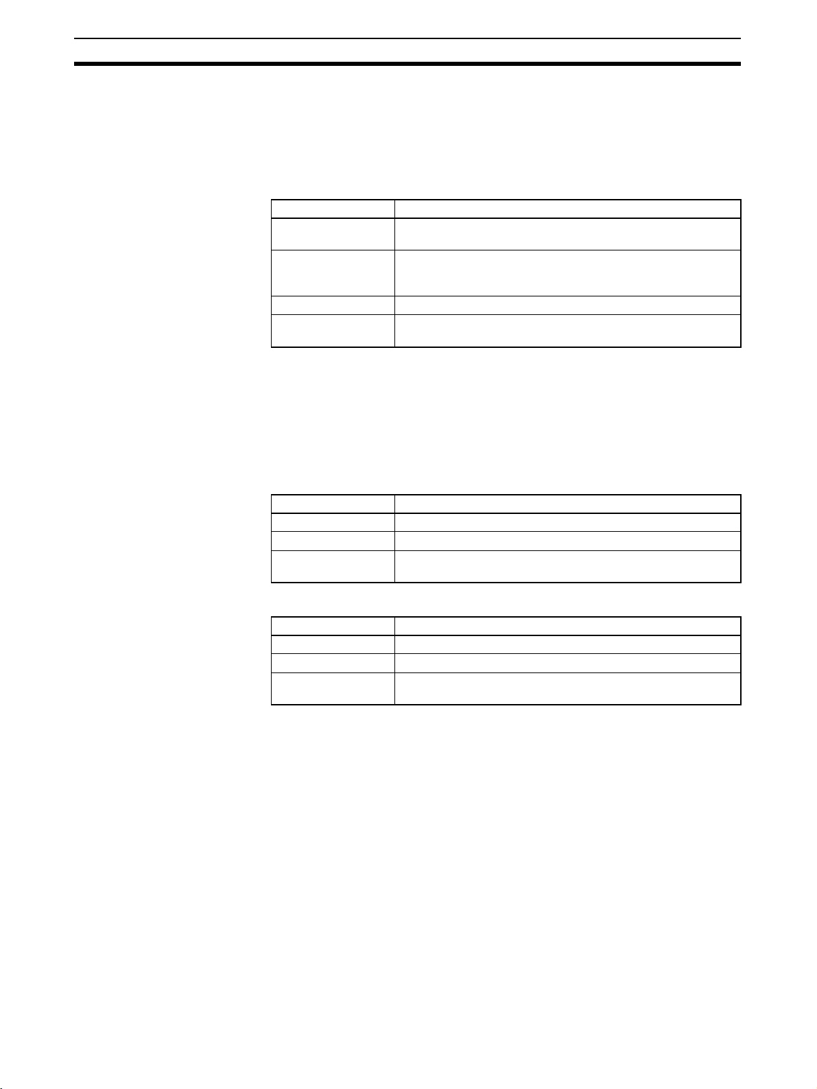
Instance Specifications Section 2-2
(2) Bit data can be accessed even if the DM or EM Area is specified for the
non-retained area or retained area.
(3) The same bank number cannot be specified as the current bank in the
user program if the EM Area is specified for the non-retained area or retained area.
Retained Area
Item Contents
Allocated variables Variables for which the retain property for power OFF and
Applicable areas H (Function block Special Holding Area), H (Holding Area), D
Setting unit Set in words
Allocated words
(default)
Note (1) Except when the data type is set to TIMER or COUNTER.
(2) Bit data can be accessed even if the DM or EM Area is specified for the
non-retained area or retained area.
(3) The same bank number cannot be specified as the current bank in the
user program if the EM Area is specified for the non-retained area or retained area.
operation start is set as retained (See note 1.)
(Data Memory Area) (see note 1), E (Extended Data Memory
Area) (See notes 2 and 3.)
H1408 to H1535
Function Block Holding
Area (H512 to H1535)
Timer Area
Item Contents
Allocated variables Variables with TIMER set as the data type.
Applicable areas T (Timer Area) Timer Flag (1 bit) or timer PVs (16 bits)
Allocated words
(default)
T3072 to T4095 Timer Flag (1 bit) or timer PVs (16 bits)
Counter Area
Item Contents
Allocated variables Variables with COUNTER set as the data type.
Applicable areas C (Counter Area) Counter Flag (1 bit) or counter PVs (16 bits)
Allocated words
(default)
C3072 to C4095 Counter Flag (1 bit) or counter PVs (16 bits)
The default allocation of Function Block Holding Area words set as retained
and non-retained words is H512 to H1535. These words are different to the
standard Holding Area used for programs (H000 to H511), and are used only
for the function block instance area (internally allocated variable area).
• These words cannot be specified in AT settings for internal variables.
• These words cannot be specified as instruction operands.
• These words are displayed in red if they are input when a function
block is not being created.
• Although the words can be input when creating a function block, an
error will occur when the program is checked.
• If this area is specified as non-retained, turn the power ON/OFF or clear
the area without retaining the values when starting operation.
32
Note To prevent overlapping of instance area addresses with addresses used in the
program, set H512 to H1535 (Function Block Holding Area words) for the nonretained area and retained area.
Page 48

Instance Specifications Section 2-2
Accessing Function Block
Instance Area from the
User Program
Note The allocations in the function block instance area for variables are automati-
If the user program contains an instruction to access the function block
instance area, an error will be displayed in the Compile Tab of the Output Window of CX-Programmer if the following operations are attempted.
• Attempting to write during online editing (writing not possible)
• Executing program check (Selecting Compile from the Program Menu or
Compile All PLC Programs from the PLC Menu)
Example: If W0 to W511 is specified as the non-retained area of the function
block instance area and W0.00 is used in the ladder program, an error will
occur when compiling and be displayed as “ERROR: [omitted]...- Address W0.00 is reserved for Function Block use].
Program
FB
EN ENO
1.0P_Off
3.0W0.00
Instance data area
Non Retain
Retain
Timers
Counters
Compile error
Start
address
W0 512
Size
cally reallocated when a variable is added or deleted. A single instance
requires addresses in sequence, however, so if addresses in sequence cannot be obtained, all variables will be allocated different addresses. As a result,
unused areas will be created. If this occurs, execute the optimization operation to effectively use the allocated areas and remove the unused areas.
Comments A comment of up to 30,000 characters long can be entered.
Creating Multiple
Instances
Calling the Same Instance A single instance can be called from multiple locations. In this case, the inter-
nal variables will be shared.
Making Multiple Instances Multiple instances can be created from a single function block definition. In
this case, the values of internal variables will be different in each instance.
Example: Counting Product A and Product B
Prepare a function block definition called Down Counter (CTD) and set up
counters for product A and product B. There are two types of programs, one
for automatic operation and another for manual operation. The user can
switch to the appropriate mode of operation.
In this case, multiple instances will be created from a single function block.
The same instance must be called from multiple locations.
33
Page 49

Instance Specifications Section 2-2
Program 1 (automatic operation)
Product A counter
CTD
CD Q
LD
PV CV
Product B counter
CTD
CD Q
LD
PV CV
Program 1
Program 2
Instance A
FB
Instance B
FB
Instance A
FB
D100
D200
Program 2 (manual operation)
Product B counter
CTD
CD Q
LD
PV CV
Reading the same product’s counter
value at different locations
Reading different products’ counter values
(Algorithm calculating counter value is the same.)
Instance A
I/O variables,
Internal
variables
Body
Instance B
I/O variables,
Internal
variables
Body
FB definition
Variable
definitions
Body
D150
Use the same internal variables
Use different internal variables
2-2-2 Parameter Specifications
The data that can be set by the user in the input parameters and output
parameters is as follows:
Item Applicable data
Input parameters Values (See note 1.), addresses, and program symbols (glo-
Output parameters Addresses, program symbols (global symbols, local symbols)
Note (1) The following table shows the methods for inputting values in parameters.
Input
variable
data type
BOOL Bit data 1 bit P_Off, P_On 0 (FALSE), 1 (TRUE)
INT Integer 16 bits Positive value: & or + followed
DINT Double integer 32 bits −2,147,483,648 to 2,147,483,647
LINT Long (8-byte) integer 64 bits −9,223,372,036,854,775,808 to
Contents Size Parameter value input
bal symbols and local symbols) (See note 2.)
Note The data that is passed to the input variable from the
parameter is the actual value of the size of the input
variable data. (An address itself will not be passed even
if an address is set in the parameter.)
Note Input parameters must be set. If even one input param-
eter has not been set, a fatal error will occur and the
input parameters will not be transferred to the actual
PLC.
(See note 2.)
Setting range
method
−32,768 to 32,767
by integer
Negative value:
integer
− followed by
9,223,372,036,854,775,807
34
Page 50

Instance Specifications Section 2-2
Input
variable
Contents Size Parameter value input
method
Setting range
data type
UINT Unsigned integer 16 bits Positive value: & or + followed
UDINT Unsigned double integer 32 bits &0 to 4,294,967,295
ULINT Unsigned long (8-byte)
64 bits &0 to 18,446,744,073,709,551,615
by integer
&0 to 65,535
integer
REAL Real number 32 bits Positive value: & or + followed
by real number (with decimal
point)
LREAL Long real number 64 bits
Negative value:
real number (with decimal
− followed by
point)
−3.402823 × 10
−38
10
, 0, 1.175494 × 10
3.402823 × 10
−1.79769313486232 × 10
−2.22507385850720 × 10
38
to −1.175494 ×
38
2.22507385850720 × 10
1.79769313486232 × 10
WORD 16-bit data 16 bits # followed by hexadecimal
#0000 to FFFF or &0 to 65,535
number (4 digits max.)
& or + followed by decimal
number
DWORD 32-bit data 32 bits # followed by hexadecimal
number (8 digits max.)
#00000000 to FFFFFFFF or &0 to
4,294,967,295
& or + followed by decimal
number
LWORD 64-bit data 64 bits # followed by hexadecimal
number (16 digits max.)
& or + followed by decimal
#0000000000000000 to
FFFFFFFFFFFFFFFF or &0 to
18,446,744,073,709,551,615
number
−38
−308
308
to
308
−308
to
, 0,
,
(2) The size of function block input variables and output variables must
match the size of program symbols (global and local), as shown in the following table.
Size Function block variable data
type
1 bit BOOL BOOL
16 bits INT, UINT, WORD INT, UINT, UINT BCD, WORD
32 bits DINT, UDINT, REAL, DWORD DINT, UDINT, UDINT BCD, REAL,
64 bits LINT, ULINT, LREAL, LWORD LINT, ULINT, ULINT BCD, LREAL,
More than 1
Non-boolean CHANNEL, NUMBER (see note)
bit
Program symbol (global, local)
data type
DWORD
LWO RD
Note The program symbol NUMBER can be set only in the input param-
eters. The value that is input must be within the size range for the
function block variable data type.
2-2-3 Operating Specifications
Calling Instances The user can call an instance from any location. The instance will be executed
when the input to EN is ON.
0.0
D0
Instance
EN ENO
A B
1.0
In this case, the input to EN is bit 0.0 at the left of the diagram.
• When the input to EN is ON, the instance is executed and
D10
the execution results are reflected in bit 1.0 and word D10.
• When the input to EN is OFF, the instance is not executed,
bit 1.0 is turned OFF, and the content of D10 is not changed.
35
Page 51

Instance Specifications Section 2-2
Operation when the
Instance Is Executed
The system calls a function block when the input to the function block’s EN
input variable is ON. When the function block is called, the system generates
the instance’s variables and copies the algorithm registered in the function
block. The instance is then executed.
Pulse_2sON_1sOFF
P_On
Algorithm (Image)
CLOCK PULSE
EN ENO
&20
ON_TIME
&10
OFF_TIME
Usage
Internal
Internal
Input
Input
Pulse_2sON_1sOFF tim_b
Pulse_2sON_1sOFF tim_a
Pulse_2sON_1sOFF tim_a
Pulse_2sON_1sOFF tim_b Pulse_2sON_1sOFF ON_TIME
1.0
1. The FB is called.
2. The system generates the instance
variables and copies the algorithm.
FB instance (Pulse_2sON_1sOFF)
Name
200-100ms_PULSE_tim_a
200-100ms_PULSE_tim_b
200-100ms_PULSE_ON_TIME
200-100ms_PULSE_OFF_TIME
Pulse_2sON_1sOFF ENO
---
--&20
&10
Pulse_2sON_1sOFF OFF_TIME
Value
Algorithm (Body)
tim_b
tim_a
3. The contents of the
TIMX tim_a OFF_TIME
TIMX tim_b ON_TIME
ENO
instance are executed.
The order of execution is as follows:
1. Read data from parameters to input variables.
2. Execute the algorithm.
3. Write data from output variables to parameters.
Input to EN is ON.
Parameters
1. Read values from parameters
to input variables.
2. Execute the algorithm.
3. Write values from output
variables to parameters.
Parameters
Data cannot be exchanged with parameters in the algorithm itself.
In addition, if an output variable is not changed by the execution of the algorithm, the output parameter will retain its previous value.
36
Page 52

Restrictions on Function Blocks Section 2-3
a
Operation when the
Instance Is Not Executed
!Caution An instance will not be executed while its EN input variable is OFF, so Differ-
When the input to the function block’s EN input variable is OFF, the function
block is not called, so the internal variables of the instance do not change (values are retained). In the same way the output variables do not change when
EN is OFF (values are retained).
Program
FB
EN ENO
Execution results:
Output variable 1.0 is turned OFF, but
internal variable a retains its previous value.
Program
Internal
variable a
1.0P_Off
1.0P_Off P_On
FB definition
Body
P_On
ENO
Internal
variable a
If the programming were entered
directly into the program instead of in
function block definition, both bit 1.0
and variable a would be turned OFF.
entiation and Timer instructions will not be initialized while EN is OFF. If Differentiation or Timer instructions are being used, use the Always ON Flag
(P_On) for the EN input condition and include the instruction’s input condition
within the function block definition.
Nesting
A function block cannot be called from another function block, i.e., nesting is
not supported.
Program
Instance A
FB1
2-3 Restrictions on Function Blocks
Ladder Programming
Restrictions
Instructions Prohibited in
Function Block Definitions
There are some restrictions on instructions used in ladder programs.
The following instructions cannot be used in function block definitions. A compile error will occur if any of these instructions is used.
• Block Programming Instructions (All instructions, including BPRG and
BEND)
• Subroutine Instructions (SBS, GSBS, RET, MCRO, SBN, GSBN, and
GRET)
• Jump Instructions (JMP, CJP, CJPN, and JME)
• Step Instructions (STEP and SNXT)
• Immediate Refresh Instructions (!)
• I/O REFRESH Instruction (IORF)
• TMHH and TMHHX Instructions
• CV Address Conversion Instructions (FRMCV and TOCV)
Instance A: FB1
FB2
Instance X: FB2
37
Page 53

Restrictions on Function Blocks Section 2-3
• Instructions manipulating record positions (PUSH, FIFO, LIFO, SETR,
and GETR)
• FAILURE POINT DETECTION Instruction (FPD)
• Move Timer/Counter PV to Register Instruction (MOVRW)
AT Setting Restrictions
(Unsupported Data Areas)
Addresses in the following areas cannot be used for AT settings.
• Index Registers (neither indirect nor direct addressing is supported) and
Data Registers
Note Input the address directly, not the AT setting.
• Indirect addressing of DM or EM Area addresses (Neither binary-mode
nor BCD-mode indirect addressing is supported.)
Direct Addressing of I/O
Memory in Instruction
Operands
• Addresses, not variables, can be directly input in Index Registers (both
indirect and direct addressing) and Data Registers.
The following values can be input in instruction operands:
Direct addressing: IR0 to IR15; Indirect addressing: ,IR0 to ,IR15; Constant offset (example): +5,IR0; DR offset: DR0,IR0; Auto-increment:
,IR0++; Auto-decrement: --,IR0
• Direct addressing in instruction operands is not supported for any other
areas in I/O memory.
I/O Variable Restrictions
(Unsupported Data Areas)
Addresses in the following data areas cannot be used as parameters for input
and output variables.
• Index Registers (neither indirect nor direct addressing is supported) and
Data Registers
• Indirect addressing of DM or EM Area addresses (Neither binary-mode
nor BCD-mode indirect addressing is supported.)
Interlock Restrictions When a function block is called from an interlocked program section, the con-
tents of the function block definition will not be executed. The interlocked function block will behave just like an interlocked subroutine.
P_Off
IL
FB
FB_BODY
Differentiation
Instructions in Function
Block Definitions
38
ILC
Interlocked
Interlock will not
affect instructions in
the function block
definition.
An instance will not be executed while its EN input variable is OFF, so the following precautions are essential when using a Differentiation Instruction in a
function block definition. (Differentiation Instructions include DIFU, DIFD, and
any instruction with an @ or % prefix.)
• As long as the instance’s EN input variable is OFF, the execution condition
will retain its previous status (the last status when the EN input variable
was ON) and the Differentiation Instruction will not operate.
• When the instance’s EN input variable goes ON, the present execution
condition status will not be compared to the last cycle’s status. The
present execution condition will be compared to the last condition when
the EN input variable was ON, so the Differentiation Instruction will not
operate properly. (If the EN input variable remains ON, the Differentiation
Instruction will operate properly when the next rising edge or falling edge
occurs.)
Page 54

Restrictions on Function Blocks Section 2-3
Example:
0.0
FB1
EN ENO
IN1 OUT1
SET OUT1
Body
LD EN
OR IN1
These Differentiation Instructions do not
operate when input condition 0.00 goes
from OFF to ON the first time.
The instructions do not operate while
input condition 0.00 is OFF.
If Differentiation Instructions are being used, always use the Always ON Flag
(P_On) for the EN input condition and include the instruction’s input condition
within the function block definition.
P_On
0.00
FB1
EN ENO
a O UT1
IN 1
LD a
OR IN1
SET OUT1
Body
The EN input condition is always ON, so
these Differentiation Instructions operate
normally.
• Input a decimal numerical value after “#” when specifying the first operand
of the following instructions.
MILH(517), MILR(518), MILC(519), DIM(631), MSKS(690), MSKR(692),
CLI(691), FAL(006), FALS(007), TKON(820), TKOF(821)
Note “&” is not supported.
• CNR(545), CNRX(547) (RESET TIMER/COUNTER) instructions cannot
be used to reset multiple timers and counters within a function block at the
same time.
Always specify the same variable for the first operand (timer/counter number 1) and second operand (timer/counter number 2). Different variables
cannot be specified for the first and second operand.
Timer Instructions in
Function Block Definitions
An instance will not be executed while its EN input variable is OFF, so the following precautions are essential when using a Timer Instruction in a function
block definition.
The Timer Instruction will not be initialized even though the instance’s EN
input variable goes OFF. Consequently, the timer’s Completion Flag will not be
turned OFF if the EN input variable goes OFF after the timer started operating.
0.00
FB1
EN ENO
U P
LD EN
TIM t im UP
Body
The timer’s Completion Flag (UP)
will not be turned OFF even though
input condition 0.00 goes OFF.
If Timer Instructions are being used, always use the Always ON Flag (P_On)
for the EN input condition and include the instruction’s input condition within
the function block definition.
39
Page 55

Restrictions on Function Blocks Section 2-3
ST Programming
Restrictions
P_On
0.00
FB1
EN ENO
a U P
LD a
TIM t im UP
Body
The timer’s completion flag (UP) is turned
OFF when input condition a (0.00) goes OFF.
• If the same instance containing a timer is used in multiple locations at the
same time, the timer will be duplicated.
• Only the following statements and operators are supported.
• Assignment statements
• Selection statements (CASE and IF statements)
• Iteration statements (FOR, WHILE, REPEAT, and EXIT statements)
• RETURN statements
• Arithmetic operators
• Logical operators
• Comparison operators
• Numerical Functions
• Arithmetic Functions
•Comments
• The TIMER and COUNTER data types cannot be used.
For further details, refer to Appendix B Structured Text (ST Language) Specifi-
cations.
Program Structure Precautions
No Branches to the Left of
the Instance
Only One Instance per
Rung
Branches are not allowed on the left side of the instance. Branches are
allowed on the right side.
Incorrect Correct
A program rung cannot have more than one instance.
FB FB
Instruction
Incorrect Incorrect
FB
FB
FB
Instruction
40
Page 56

Restrictions on Function Blocks Section 2-3
No Function Block
Connections
A function block’s input cannot be connected to another function block’s output. In this case, a variable must be registered to transfer the execution status
from the first function block’s output to the second function blocks input.
0.0
FB1
EN
XOUT
D100
XIN1
XIN2
FB2
0.0
FB1
EN
0.0
EN
D3000
XIN1
D100
XIN2
XOUT
FB2
D3000
Temporary variables
transfer the value from
FB1 to FB2.
Downloading in Task Units Tasks including function blocks cannot be downloaded in task units, but
uploading is possible.
Programming
Console Displays
When a user program created with the CX-Programmer is downloaded to the
CPU Unit and read by a Programming Console, the instances will all be displayed as question marks. (The instance names will not be displayed.)
Online Editing
Restrictions
The following online editing operations cannot be performed on the user program in the CPU Unit.
• Changing or deleting function block definitions (variable table or algorithm)
• Inserting instances or changing instance names
Note The instance’s I/O parameters can be changed, instances can be
deleted, and instructions outside of an instance can be changed.
Error-related
Restrictions
Prohibiting Access to
FB Instance Areas
If a fatal error occurs in the CPU Unit while a function block definition is being
executed, ladder program execution will stop at the point where the error
occurred.
Program FB definition
BodyInstance name
0.0
FB
EN ENO
AAA BBB
10.0
D200D100
LD P_On
++ AAA
Fatal error occurs here.
MOV AAA BBB
In this case, the MOV AAA BBB instruction will not be executed and output
variable D200 will retain the same value that it had before the function block
was executed.
To use a function block, the system requires memory areas to store the
instance’s internal variables and I/O variables.
Function block instance
area
Non-retained H512 896 CIO, WR, HR, DM, EM
Retained H1408 128 HR, DM, EM
Timer T3072 1,024 TIM
Counter C3072 1,024 CNT
Initial value of
start address
Initial value
of size
Allowed data areas
If there is an instruction in the user program that accesses an address in an
FB instance area, the CX-Programmer will output an error in the following
cases.
41
Page 57

Function Block Applications Guidelines Section 2-4
• When a program check is performed by the user by selecting Program Compile from the Program Menu or Compile All Programs from the
PLC Menu.
• When attempting to write the program through online editing (writing is
not possible).
2-4 Function Block Applications Guidelines
This section provides guidelines for using function blocks with the CX-Programmer.
2-4-1 Deciding on Variable Data Types
Integer Data Types
(1, 2, or 4-word Data)
Note Use signed integers if the numbers being used will fit in the range.
Word Data Types
(1, 2, or 4-word Data)
Use the following data types when handling single numbers in 1, 2, or 4-word
units.
• INT and UINT
• DINT and DINT
• LINT and ULINT
Use the following data types when handling groups of data (non-numeric
data) in 1, 2, or 4-word units.
•WORD
•DWORD
•LWORD
2-4-2 Determining Variable Types (Inputs, Outputs, Externals, and
Internals)
Using Input Variable to
Change Passed Values
To paste a function block into the program and then change the value (not the
address itself) to be passed to the function block for each instance, use an
input variable.
Program
Instance for function block definition A
The value itself is
passed
42
&3 Unit No.
&50
Changing the pass value to an input variable.
The following two restrictions apply.
• An address can be set in an input parameter, but an address itself cannot
be passed to an input variable (even if an address is set in the input
parameter, the value for the size of the input variable data type is passed
to the function block). Therefore, when the first or last of multiple words is
specified in the instruction operand within the function block, an input variable cannot be used for the operand. Specify either to use internal variables with AT settings, specify the first or last element in an internal array
variable, or use an external variable (as described in 2-4-4 Array Settings
for Internal Variables).
PARA
Page 58

Function Block Applications Guidelines Section 2-4
An input variable cannot be used to specify
Program
Instance for function block definition A
The actual value is
passed
D00100 DATA_1
W500
DATA_2
The address can be specified, but the address itself is not passed.
If the size of the data type in
DATA_1 is 1 word, the value
for the word D00100 is
passed.
If the size of the data type in
DATA_2 is 2 words, the value
for the 2 words W500 and
W501 is passed.
• Values are passed in a batch from the input parameters to the input variables before algorithm execution (not at the same time as the instruction
in the algorithm is executed). Therefore, to pass the value from a parameter to an input variable when the instruction in the function block algorithm
is executed, use an internal variable or external variable instead of an
input variable.
the address of an operand that specifies
the the first (or last) address of multiple
words.
For example, the XFER (BLOCK
TRANSFER) instruction cannot be used to
transfer 10 words from the address
beginning with DATA_1 to the address
beginning with DATA_2.
XFER
&10
DATA_1
DATA_2
Passing Values from or
Monitoring Output
Variables
External Variables:
Condition Flags, Clock
Pulses, Auxiliary Area
Bits, Global Symbols in
Program
Internal Variables:
Internally Allocated
Variables and Variables
Requiring AT Settings
To paste into the program and then pass values outside (the program) from
the function block for each instance, or monitor values, use output variables.
Program
Instance for function block definition A.
The actual value is
passed.
OK_Flag
NG_Flag
Variable for passing a value outside or monitoring:
Use an output variable.
W0.00
W0.01
The following restrictions apply.
• Values are passed from output variables to output parameters all at once
after algorithm execution.
Condition Flags (e.g., Always ON Flag, Equals Flag), Clock Pulses (e.g., 1.0
second clock pulse bit), pre-registered Auxiliary Area Bits (e.g., First Cycle
Flag), and global symbols used in the program are all external variables
defined by the system.
Variables that are not specified as Inputs, Outputs, or Externals are Internals.
Internal variables include variables with internally allocated addresses, variables requiring addresses with AT settings (e.g., I/O allocation addresses,
addresses specially allocated for Special I/O Units), or variables requiring
array settings. For details on conditions requiring AT settings or array settings,
refer to 2-4-3 AT Settings for Internal Variables, and 2-4-4 Array Settings for
Internal Variables.
2-4-3 AT Settings for Internal Variables
Always specify AT settings for internal variables under the following conditions.
• When addresses allocated to Basic I/O Units, Special I/O Units, or CPU
Bus Units are used and these addresses are registered to global symbols
that cannot be specified as external variables (e.g., data set for global
symbols is unstable).
43
Page 59

Function Block Applications Guidelines Section 2-4
p
Note The method for specifying Index Registers for Special I/O Unit allo-
cation addresses requires AT settings to be specified for the first
address of the allocation area. (For details, refer to 2-4-5 Specifying
Addresses Allocated to Special I/O Units.)
• When Auxiliary Area bits that are not pre-registered to external variables
are used, and these bits are registered to global symbols that are not
specified as external variables.
• When setting the first destination word at the remote node for SEND(090)
and the first source word at the local node for RECV(098).
• When the instruction operand specifies the first or last of multiple words,
and internal array variable cannot be specified for the operand (e.g., the
number of array elements cannot be specified).
2-4-4 Array Settings for Internal Variables
Using Array Variables
to Specify First or Last
Word in Multiword
Operands
1,2,3... 1. Prepare an internal array variable with the required number of elements.
When specifying the first or last of a range of words in an instruction operand
(see note), the instruction operates according to the address after AT specification or internal allocation. (Therefore, the variable data type and number of
elements for the variable are unrelated to the operation of the instruction.) Always specify a variable with an AT setting or an array variable with a number
of elements that matches the data size to be processed by the instruction.
Note Some examples are the first source word or first destination word of the
XFER(070) (BLOCK TRANSFER) instruction, the first source word for
SEND(090), or control data for applicable instructions.
For details, refer to 2-5 Precautions for Instructions with Operands Specifying
the First or Last of Multiple Words. Use the following method to specify an array
variable.
Note Make sure that the data size to be processed by the instruction is
the same as the number of elements. For details on the data sizes
processed by each instruction, refer to 2-6 Instruction Support and
Operand Restrictions.
2. Set the data in each of the array elements using the MOV instruction in the
function block definition.
3. Specify the first (or last) element of the array variable for the operand. This
enables specification of the first (or last) address in a range of words.
Examples are provided below.
44
Handling a Single String of Data in Multiple Words
In this example, an array contains the directory and filename (operand S2) for
an FREAD instruction.
• Variable table
Internal variable, data type = WORD, array setting with 10 elements, variable names = filename[0] to filename[9]
• Ladder programming
MOV #5C31 file_name[0]
MOV #3233 file_name[1]
MOV #0000 file_name[2])
FREAD (omitted) (omitted) file_name[0] (omitted)
Set data in each array element.
Specify the first element
of the array in the instruction
erand.
o
Page 60

Function Block Applications Guidelines Section 2-4
Handling Control Data in Multiple Words
In this example, an array contains the number of words and first source word
(operand S1) for an FREAD instruction.
• Variable table
Internal variable, data type = DINT, array setting with 3 elements, variable
names = read_num[0] to read_num[9]
• Ladder programming
MOVL &100 read_num[0] (No._of_words)
MOVL &0 read_num[1] (1st_source_word)
FREAD (omitted) read_num[0] (omitted) (omitted)
Handling a Block of Read Data in Multiple Words
The allowed amount of read data must be determined in advance and an
array must be prepared that can handle the maximum amount of data. In this
example, an array receives the FREAD instruction’s read data (operand D).
• Variable table
Internal variable, data type = WORD, array setting with 100 elements,
variable names = read_data[0] to read_data[99]
• Ladder programming
FREAD (omitted) (omitted) (omitted) read_data[0]
Set data in each array element.
Specify the first element of the array
in the instruction operand.
Division Using Integer
Array Variables (Ladder
Programming Only)
A two-element array can be used to store the result from a ladder program’s
SIGNED BINARY DIVIDE (/) instruction. The result from the instruction is D
(quotient) and D+1 (remainder). This method can be used to obtain the remainder from a division operation in ladder programming.
Note When ST language is used, it isn’t necessary to use an array to receive the
result of a division operation. Also, the remainder can’t be calculated directly
in ST language. The remainder must be calculated as follows:
Remainder = Dividend
− (Divisor × Quotient)
2-4-5 Specifying Addresses Allocated to Special I/O Units
Use Index Registers IR0 to IR15 (indirectly specified constant offset) to specify addresses allocated to Special I/O Units based on the value passed for the
unit number as an input parameter within the function block definition as
shown in the following examples.
Note For details on using Index Registers in function blocks, refer to 2-4-6 Using
Index Registers.
Examples
Example 1: Specifying the CIO Area within a Function Block (Same for DM
Area)
Special I/O Units
Variables: Use the unit number as an input variable, and specifying the first
allocation address as an internal variable with the AT set to CIO 2000.
Programs: Use the following procedure.
1,2,3... 1. Multiply the unit number (input variable) by &10, and create the unit num-
ber offset (internal variable, DINT data type).
2. Use the MOVR(560) (MOVE TO REGISTER) instruction to store the real I/
O memory address for the first allocation address (internal variable, AT =
CIO 2000) in the Index Register (e.g., IR0).
45
Page 61

Function Block Applications Guidelines Section 2-4
3. Add the unit number offset to the real I/O memory address within the Index
Register (e.g., IR0).
Example 2: Specifying the Designated Bit in the CIO Area (e.g., CIO Word
n+a, Bit b)
Programs: Use either of the following methods.
• Word addresses: Specify the constant offset of the Index Register using
an indirect specification (e.g., +a,IR0).
• Bit addresses: Specify an instruction that can specify a bit address within
a word (e.g., &b in second operand of SETB instruction when writing and
TST instruction when reading).
Example: Special I/O Units
Instance for function block definition A.
&3 Unit No.
1) Specify the first CIO Area word n (n = CIO 2000 + unit number × 10)
Used constants:
Unit number (input variable, INT data type)
Offset (internal variable, DINT data type)
Relay (internal variable, WORD data type, 400 array elements, AT
setting = 2000)
Multiplies unit number by
&10
&10 and stores in offset.
Unit No.
Offset
Stores the real I/O memory
MOVR
address for the relay in IR0.
Relay
IR0
2-4-6 Using Index Registers
Index Registers IR0 to IR15 function as pointers for specifying I/O memory
addresses. These Index Registers can be used within function blocks to
directly specify addresses using IR0 to IR15 and not the variable names
(Index Register direct specification: IR0 to IR15; Index Register indirect specification: ,IR0 to ,IR15)
Note After storing the real I/O memory addresses in the Index Registers using the
MOVR(560) instruction, Index Registers can be indirectly specified using general instructions. This enables all I/O memory areas to be specified dynamically.
Adds offset to IR0.
+L
IR0
Offset
IR0
2) Specify the designated bit in the CIO
Area (e.g., CIO word n+1, bit 02)
Turns ON CIO word n+1,
SETB
bit 02.
+1,IR0
&2
46
Page 62

Function Block Applications Guidelines Section 2-4
Pointer
All I/O memory
areas
MOVR(560)
IR@
Index Register
Example: Specifying +5,IR0 using
constant offset specification, not
variable name
Function block
Instruction
+5,IR0
a
Indirect
specification
Specify address
in IR0
+5 offset
Specify address at +5
IR0
offset from
I/O memory
IR0.
Note (1) When Index Registers IR0 to IR15 are used within function blocks, using
the same Index Register within other function blocks or in the program
outside of function blocks will create competition between the two instances and the program will not execute properly. Therefore, when using
Index Registers (IR0 to IR15), always save the value of the Index Register
at the point when the function block starts (or before the Index Register
is used), and when the function block is completed (or after the Index
Register has been used), incorporate processing in the program to return
the Index Register to the saved value.
Example: Starting function block (or before using Index Register):
1. Save the value of IR (e.g., A).
Value A
Value A
IR0
Value A
Within function block:
2.Use IR.
Value B
IR0
At start of function block (or before Index Register is used):
3. Return IR to saved valuev(e.g., A)
Value A
IR0
Value A
(2) Always set the value before using Index Registers. Operation will not be
stable if Index Registers are used without the values being set.
47
Page 63
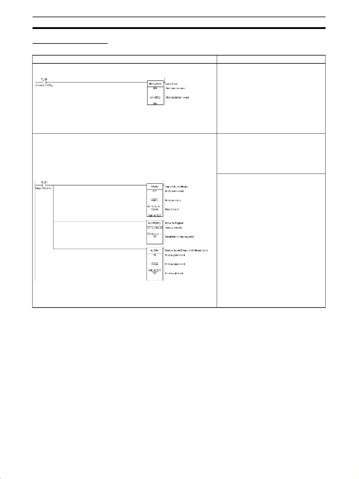
Function Block Applications Guidelines Section 2-4
Application Examples The following examples are for using Index Registers IR0 to IR15 within func-
tion blocks.
Example Details
Saving the Index Register Value before Using Index Register When Index Registers are used within this
Store IR0 temporarily in backup buffer
Using Index Registers
1) Setting the value in the Index Register. (Stores the real I/O memory
address for first CIO Area word n)
Calculate offset address from unit number
function block, processing to save the Index
Register value is performed when the function starts (or before the Index Register is
used) to enable the value to be returned to
the original Index Register value after the
function block is completed (or after the
Index Register is used).
Example: Save the contents of Index Register IR0 by storing it in SaveIR[0] (internal
variable, data type DINT, 1 array element).
Example: The real I/O memory address for
the first word of CIO 1500 + unit number
25 allocated in the CPU Bus Unit allocation
area based on the CPU Bus Unit’s unit
number (&0 to &15) passed from the function block is stored in IR0.
Procedure:
Assumes that unit numbers &0 to &15 have
already been input (from outside the function block) in UnitNo (input variables, INT
data type).
1. Multiple UnitNo by &25, and store in Off-
set (internal variable, DINT data type)
2. Store the real I/O memory address for
SCPU_Relay (internal variable, WORD
data type, (if required, specify the array as
400 elements (see note), AT setting =
1500)) in Index Register IR0.
Note Specifying an array for SCPU_relay,
such as SCPU_relay [2], for example,
enables the address CIO 1500 +
(UnitNo
This also applies in example 2 below.
3. Increment the real I/O memory address
in Index Register IR0 by the value for the
variable Offset (variable UnitNo
× &25) + 2 to be specified.
×
× &25).
48
Page 64

Precautions for Instructions with Operands Specifying the First or Last of Multiple Section 2-5
Example Details
2) Specifying constant offset of Index Register (Specifying a bit between
CIO n+0 to n+24)
Check local node data link participation
The real I/O memory address for CIO 1500
+ (UnitNo
IR0 by the processing in step 1 above.
Therefore the word address is specified
using the constant offset from IR0.
For example, specifying +2,IR0 will specify
CIO 1500 + (UnitNo
Note CIO 1500 + (UnitNo × &25) + 2 can
Specify bit addresses using instructions that
can specify bit addresses within words
(e.g., second operand of TST(350/351)/
SETB(532) instructions).
Example: Variable NodeSelf_OK turns ON
when NetCheck_OK (internal variable,
BOOL data type) is ON and bit 15 of the
word at the +6 offset from IR0 (CIO 1500 +
UnitNo
× &25) is stored in Index Register
× &25) + 2.
also by specified by specifying
SCPU_relay [2] using the array setting with SCPU_relay.
× &25 +6) is ON.
Returning the Index Register to the Prior Value The Index Register returns to the original
Restore data to IR0 from temporary backup buffer
value after this function block is completed
(or after the Index Register has been used).
Example: The value for variable SaveIR[0]
that was saved is stored in Index Register
IR0, and the value is returned to the contents from when this function started (or
prior to using the Index Register).
2-5 Precautions for Instructions with Operands Specifying the
First or Last of Multiple Words
When using ladder programming to create function blocks with instruction
operands specifying the first or last of a range of words, the following precautions apply when specifying variables for the operand.
When the operand specifies the first or last word of multiple words, the
instruction operates according to the internally allocated address for AT setting (or external variable setting). Therefore, the variable data type and number of array elements are unrelated to the operation of the instruction. Either
specify a variable with an AT setting, or an array variable with a size that
matches the data size to be processed by the instruction.
For details on whether an AT setting (or external variable setting) or an array
setting for a number of elements is required to specify the first address of a
range of words in the instruction operand, refer to 2-6 Instruction Support and
Operand Restrictions.
Note To specify the first or last of multiple words in an instruction operand, always
specify a variable with AT setting (or an external variable), or a variable with
the same size as the data size to be processed in the instruction. The following precautions apply.
1,2,3... 1. If a non-array variable is specified without AT setting and without a match-
ing data size, the CX-Programmer will output an error when compiling.
2. The following precautions apply to when an array variable is specified.
49
Page 65

Precautions for Instructions with Operands Specifying the First or Last of Multiple Section 2-5
Size to Be Processed in the Instruction Operand Is Fixed
Make sure that the number of elements in the array is the same as size to be
processed by the instruction. Otherwise, the CX-Programmer will output an
error when compiling.
Size to Be Processed in the Instruction Operand Is Not Fixed
Make sure that the number of elements in the array is the same or greater
than the size specified by another operand.
Other Operand Specifying Size: Constant
The CX-Programmer outputs an error when compiling.
Other Operand Specifying Size: Variable
The CX-Programmer will not output an error when compiling (a warning message will be displayed) even if the number of elements in the array does not
match the size specified in another operand (variable).
In particular, when the number of elements in the array is less than the size
specified by another operand, (for example, when instruction processing size
is 16 and the number of elements actually registered in the variable table is
10), the instruction will execute read/write processing in the areas exceeding
the number of elements. (In this example, read/write processing will be executed for the next 6 words after the number of elements registered in the
actual variable table.) If the same area is being used by another instruction
(including internal variable allocations), unexpected operation may occur,
which may result in a serious accident.
Do not use variables with a size that does not match the data size to be processed by the instruction in the operand specifying the first address (or last
address) for a range of words. Always use either non-array variables data type
with a size that is the same as the data size required by the instruction or
array variable with the number of elements that is the same as the data size
required by the instruction. Otherwise, the following errors will occur.
Non-array Variables
without Matching Data
Size and without AT
Setting
Example: XFER &10 a b
(variables a and b are WORD data types)
Internally allocated address Internally allocated address
Example: H700
If the operand specifying the first address (or last address) of multiple words
uses a non-array variable data type with a size that does not match the data
size required by the instruction and an AT setting is also not used, the CX-Programmer will output a compile error.
Example: BLOCK TRANSFER(070) instruction: XFER W S D
(W: Number of words, S: First source word; D: First destination word)
When &10 is specified in W, variable a with data type WORD is specified in S,
and variable b with data type WORD is specified in D: XFER &10 a b
The XFER(070) instruction will transfer the data in the 10 words beginning from
the automatically allocated address in variable a to the 10 words beginning
with the automatically allocated address in variable b. Therefore, the CX-Programmer will output a compile error.
Example: H7@@
10 words are
transferred regardless of the size of
variable a.
Variable b (1 word)Variable a (1 word)
This area will be overwritten,
so the CX-Programmer will
output a compile error.
50
Page 66

Precautions for Instructions with Operands Specifying the First or Last of Multiple Section 2-5
Array Variables The result depends on the following conditions.
Size to Be Processed by Instruction Is Fixed
If the size to be processed by the instruction is a fixed operand, and this size
does not match the number of array elements, the CX-Programmer will output
a compile error.
Example: LINE TO COLUMN(064) instruction; COLM S D N
(S: Bit number, D: First destination word, N: Source word)
E.g., COLM a b[0] c
If an array for a WORD data type with 10 array elements is specified in D
when it should be for 16 array elements, the CX-Programmer will output an
error when compiling.
Size to Be Processed by Instruction Is Not Fixed
When the operand size to be processed by the instruction is not fixed (when
the size is specified by another operand in the instruction), make sure that the
number of array elements is the same or greater than the size specified in the
other operand (i.e., size to be processed by the instruction).
Other Operand Specifying Size: Constant
The CX-Programmer will output an error when compiling.
Example: BLOCK TRANSFER: XFER W S D
(W: Number of words, S: First source word; D: First destination word)
When &20 is specified in W, array variable a with data type WORD and 10
elements is specified in S, and array variable b with data type WORD and 10
elements is specified in D:
XFER &20 a[0] b[0]
Even though the array variables a[0] and b[0] are both 10 words, the
XFER(070) instruction will execute transfer processing for the 20 words specified in W. As a result, the XFER(070) instruction will perform read/write processing for the I/O memory area following the number of array elements that
was allocated, as shown in the following diagram.
Therefore, if a[10 elements] is internally allocated words (e.g., H700 to H709),
and b[10 elements] is internally allocated words (e.g., H800 to H809),
XFER(070) will transfer data in words H700 to H719 to words H800 to H819.
In this operation, if another internally allocated variable (e.g., c), is allocated
words in H810 to H819, the words will be overwritten, causing unexpected
operation to occur. To transfer 20 words, make sure that the number of elements is specified as 20 elements for both array variable a and b.
51
Page 67

Instruction Support and Operand Restrictions Section 2-6
XFER &20 a[0] b[0]
Using a WORD data type with 10 elements for both variables a and b:
To transfer 20 words, be sure to specify 20 elements for both array variables a and b.
Internally allocated address Internally allocated address
Example: H700
10 words
Array variable
a (10 words)
20 words
Array variable
a (10 words)
10 words
Example: H710
Example: H719
Example: H810
20 words will be
transferred regardless of the size of array variables a and b.
Example: H819
The variables allocated in this area
(H810 to H819 in this example) are
overwritten. The data is variablelength data, so the CX-Programmer
will not output a compile error.
Other Operand Specifying Size: Variable
Even if the number of array elements does not match the size (i.e., size to be
processed by the instruction) specified in another operand (variable), the CXProgrammer will not output an error when compiling. The instruction will be
executed according to the size specified by the operand, regardless of the
number of elements in the array variable.
Particularly if the number of elements in the array is less than the size (i.e.,
size to be processed by the instruction) specified by another operand (variable), other variables will be affected and unexpected operation may occur.
2-6 Instruction Support and Operand Restrictions
The tables in this appendix indicate which instructions can be used in function
blocks created with ladder programming language, the restrictions that apply
to them and to the operands, including the variables (whether array variables
and AT settings or external variable specifications are required, and which
data types can be used).
Instruction Support Instructions that are not supported for use in function block definitions by the
CX-Programmer and CS/CJ-series CPU Units with unit version 3.0 are given
as Not supported in function blocks in the Symbol column.
Restrictions on Operands • Operands that specify the first or last of multiple words, thereby requiring
AT setting or specification of array variables, are indicated as follows in
the AT setting or array required column.
Yes: An AT setting (or external specification) or array variable must be
specified for the operand to specify the first or last of multiple words.
• The value within parentheses is the fixed size used by the instruction
for reading, writing, or other processing. This size indicates either the
data type size or the size required for the array variable specified in
word units. For array variables, this size must be the same as the number of elements. Otherwise, the CX-Programmer will output an error
when compiling.
52
Page 68

Instruction Support and Operand Restrictions Section 2-6
k
k
• If “not fixed” is indicated in parentheses, the size used by the instruction for reading, writing, or other processing can be changed. Make
sure that the maximum size required for the number of array elements
is provided.
Even if the number of array elements in an operand with unfixed size
does not match the size specified in another operand, the CX-Programmer will not output an error when compiling. The instruction will
operate according to the size specified in the other operand, regardless of the number of array variable elements.
---: Operands that do not require an AT setting or specification of array variables.
Note When specifying the first or last word of multiple words in an in-
struction operand, input parameters cannot be used to pass data
to or from variables. Either an AT setting or an array variable with
the required number of elements must be prepared, and after the
array data is set in the function block definition, the first or last element in the array variable must be specified for the operand.
• Any operands for which an AT setting must be specified for an I/O memory address on a remote node in the network are indicated as Specify
address at remote node with AT setting in the AT setting or array required
column.
2-6-1 Sequence Input Instructions
Instruction Mnemonic Function
code
LOAD LD
@LD
%LD
!LD
!@LD
!%LD
LOAD NOT LD NOT
!LD NOT
@LD NOT
%LD NOT
!@LD NOT
!%LD NOT
AND AND
@AND
%AND
!AND
!@AND
!%AND
Symbol Operands Supported
Bus bar
Starting point of bloc
Bus bar
Starting point of bloc
variable
data types
(Required word
B: Bit BOOL ---
B: Bit BOOL ---
B: Bit BOOL ---
AT setting or
array variable
required
data size
shown in
parentheses.)
53
Page 69

Instruction Support and Operand Restrictions Section 2-6
Instruction Mnemonic Function
code
AND NOT AND NOT
!AND NOT
@AND NOT
%AND NOT
!@AND NOT
!%AND NOT
OR OR
@OR
%OR
!OR
!@OR
!%OR
OR NOT OR NOT
!OR NOT
@OR NOT
%OR NOT
!@OR NOT
!%OR NOT
Symbol Operands Supported
variable
data types
--- BOOL ---
Bus bar
Bus bar
--- BOOL ---
--- BOOL ---
AT setting or
array variable
required
(Required word
data size
shown in
parentheses.)
AND LOAD AND LD --- --- ---
Logic block Logic block
OR LOAD OR LD --- --- ---
Logic block
Logic block
NOT NOT 520 --- --- ---
CONDITION ONUP 521 --- --- ---
CONDITION
DOWN 522 --- --- ---
OFF
NOT
UP
DOWN
BIT TEST LD TST 350 S: Source word WORD ---
TST
S
N
N: Bit number UINT ---
BIT TEST LD TSTN 351 S: Source word WORD ---
TSTN
S
N
N: Bit number UINT ---
54
Page 70

Instruction Support and Operand Restrictions Section 2-6
Instruction Mnemonic Function
code
Symbol Operands Supported
variable
data types
(Required word
BIT TEST AND TST 350 S: Source word WORD ---
AND TST
S
N
N: Bit number UINT ---
BIT TEST AND TSTN 351 S: Source word WORD ---
AND TSTN
S
N
N: Bit number UINT ---
BIT TEST OR TST 350 S: Source word WORD ---
TST
S
N
N: Bit number UINT ---
BIT TEST OR TSTN 351 S: Source word WORD ---
TSTN
S
N
N: Bit number UINT ---
AT setting or
array variable
required
data size
shown in
parentheses.)
2-6-2 Sequence Output Instructions
Instruction Mnemonic Function
code
OUTPUT OUT
!OUT
OUTPUT NOT OUT NOT
!OUT NOT
KEEP KEEP
011 --- BOOL ---
!KEEP
DIFFERENTIATE U P
DIFFERENTIATE D OWN
DIFU
!DIFU
DIFD
!DIFD
013 --- BOOL ---
014 --- BOOL ---
Symbol Operands Supported
S (Set)
R (Reset)
KEEP
B
DIFU
B
DIFD
B
variable
data types
--- BOOL ---
--- BOOL ---
AT setting or
array variable
required
(Required
word data size
shown in
parentheses.)
55
Page 71

Instruction Support and Operand Restrictions Section 2-6
Instruction Mnemonic Function
code
SET SET
@SET
%SET
!SET
!@SET
!%SET
RESET RSET
@RSET
%RSET
!RSET
!@RSET
!%RSET
MULTIPLE BIT
SET
SETA
@SETA
530 D: Beginning word UINT Yes (not fixed)
Symbol Operands Supported
variable
data types
SET
B
RSET
B
SETA
D
N1
N2
B: Bit BOOL ---
B: Bit BOOL ---
N1: Beginning bit UINT --N2: Number of bits UINT ---
AT setting or
array variable
required
(Required
word data size
shown in
parentheses.)
MULTIPLE BIT
RESET
SINGLE BIT
SET
SINGLE BIT
RESET
SINGLE BIT
OUTPUT
RSTA
@RSTA
SETB
@SETB
!SETB
RSTB
@RSTB
!RSTB
OUTB
@OUTB
!OUTB
531 D: Beginning word UINT Yes (not fixed)
532 D: Word address UINT ---
533 D: Word address UINT ---
534 D: Word address UINT ---
RSTA
D
N1
N2
SETB
D
N
RSTB
D
N
OUTB
D
N
N1: Beginning bit UINT --N2: Number of bits UINT ---
N: Bit number UINT ---
N: Bit number UINT ---
N: Bit number UINT ---
56
Page 72

Instruction Support and Operand Restrictions Section 2-6
2-6-3 Sequence Control Instructions
Instruction Mnemonic Function
code
Symbol Operands Supported
variable
array variable
data types
size shown in
parentheses.)
END END 001 --- --- ---
END
NO OPERATION NOP 000 --- --- --- --INTERLOCK IL 002 --- --- ---
INTERLOCK
ILC 003 --- --- ---
CLEAR
MULTI-INTER-
MILH 517 N: Interlock number # + decimal
LOCK DIFFERENTIATION
HOLD
MULTI-INTER-
MILR 518 N: Interlock number # + decimal
LOCK DIFFERENTIATION
RELEASE
MULTI-INTER-
MILC 519 N: Interlock number # + decimal
LOCK CLEAR
MILC
N
IL
ILC
MILH
N
D
MILR
N
D
D: Interlock Status
Bit
D: Interlock Status
Bit
only
---
BOOL ---
---
only
BOOL ---
---
only
AT setting or
required
(Required
word data
JUMP JMP 004 Not supported in function
N: Jump number --- ---
blocks
JUMP END JME 005 Not supported in function
N: Jump number --- ---
blocks
CONDITIONAL
JUMP
CONDITIONAL
JUMP
MULTIPLE
JUMP
MULTIPLE
JUMP END
FOR-NEXT
LOOPS
BREAK LOOP BREAK 514 --- --- ---
FOR-NEXT
LOOPS
CJP 510 Not supported in function
N: Jump number --- ---
blocks
CJPN 511 Not supported in function
N: Jump number --- ---
blocks
JMP0 515 --- --- ---
JME0 516 --- --- ---
FOR 512 N: Number of loops UINT ---
NEXT 513 --- --- ---
JMP0
JME0
FOR
N
BREAK
NEXT
57
Page 73

Instruction Support and Operand Restrictions Section 2-6
2-6-4 Timer and Counter Instructions
Instruction Mnemonic Function
code
TIMER TIM
(BCD)
TIMX
550 N: Timer number TIMER ---
(BIN)
HIGH-SPEED
TIMER
TIMH
(BCD)
TIMHX
015 N: Timer number TIMER ---
551 N: Timer number TIMER ---
(BIN)
Symbol Operands Supported
variable
data types
TIM
N
S
TIMX
N
S
TIMH
N
S
TIMHX
N
S
N: Timer number TIMER --S: Set value WORD ---
S: Set value UINT ---
S: Set value WORD ---
S: Set value UINT ---
AT setting or
array variable
required
(Required
word data
size shown in
parentheses.)
ONE-MS TIMER TMHH
(BCD)
TMHHX
(BIN)
ACCUMULATIVE TIMER
TTIM
(BCD)
TTIMX
(BIN)
LONG TIMER TIML
(BCD)
TIMLX
(BIN)
540 Not supported in function
blocks.
552 Not supported in function
blocks.
087 N: Timer number TIMER ---
555 N: Timer number TIMER ---
Timer input
Reset input
542 D1: Completion
553 D1: Completion
TTIM
N
S
TTIMX
N
S
TIML
D1
D2
S
TIMLX
D1
D2
S
N: Timer number TIMER --S: Set value WORD --N: Timer number TIMER --S: Set value UINT ---
S: Set value WORD ---
S: Set value UINT ---
WORD ---
Flag
D2: PV word DWORD --S: SV word DWORD ---
UINT ---
Flags
D2: PV word UDINT --S: SV word UDINT ---
58
Page 74

Instruction Support and Operand Restrictions Section 2-6
Instruction Mnemonic Function
code
MULTI-OUTPUT
TIMER
MTIM
(BCD)
MTIMX
543 D1: Completion
554 D1: Completion
(BIN)
COUNTER CNT
(BCD)
CNTX
546 N: Counter number COUNTER ---
(BIN)
Count input
Reset input
Count input
Reset input
Symbol Operands Supported
variable
data types
MTIM
D1
D2
S
MTIMX
D1
D2
S
CNT
N
S
CNTX
N
S
Flags
D2: PV word WORD --S: 1st SV word WORD Yes (8)
Flags
D2: PV word UINT --S: 1st SV word WORD Yes (8)
N: Counter number COUNTER --S: Set value WORD ---
S: Set value UINT ---
UINT ---
UINT ---
AT setting or
array variable
required
(Required
word data
size shown in
parentheses.)
REVERSIBLE
COUNTER
RESET TIMER/
COUNTER
CNTR
(BCD)
CNTRX
(BIN)
CNR
@CNR
(BCD)
012 N: Counter number COUNTER ---
548 N: Counter number COUNTER ---
545 N1: 1st number in
Increment input
Decrement input
Reset input
Increment input
Decrement input
Reset input
CNTR
N
S
CNTRX
N
S
CNR
N1
N2
S: Set value WORD ---
S: Set value UINT ---
range
N2: Last number in
range
CNRX
@CNRX
(BIN)
547 N1: 1st number in
CNRX
N1
N2
range
N2: Last number in
range
Note Enabled when the same variable is specified for N1 and N2.
TIMER or
COUNTER
(See note.)
TIMER or
COUNTER
(See note.)
TIMER or
COUNTER
(See note.)
TIMER or
COUNTER
(See note.)
---
---
---
---
59
Page 75

Instruction Support and Operand Restrictions Section 2-6
2-6-5 Comparison Instructions
Instruction Mnemonic Function
Symbol Comparison (Unsigned)
LD,AND, OR
+
=, <>, <, <=,
>, >=
300 (=)
305 (<>)
310 (<)
315 (<=)
320 (>)
325 (>=)
code
Symbol Operands Supported
Using LD:
Symbol, option
Using AND:
Symbol, option
Using OR:
S1
S2
S1
S2
S1: Comparison
data 1
S2: Comparison
data 2
variable
setting or
data types
(Required
word dat a
parenthe-
UINT ---
UINT ---
AT
array
variable
required
size
shown in
ses.)
Symbol Comparison (Double-word,
unsigned)
Symbol Comparison (Signed)
Symbol Comparison (Double-word,
signed)
UNSIGNED COMPA RE
LD,AND, OR
+
=, <>, <, <=,
>, >=
+
L
LD,AND, OR
+
=, <>, <, <=,
>, >=
+
S
LD,AND, OR
+
=, <>, <, <=,
>, >=
+
SL
CMP
!CMP
Symbol, option
S1
S2
301 (=)
306 (<>)
311 (<)
316 (<=)
--- S1: Comparison
data 1
S2: Comparison
data 2
321 (>)
326 (>=)
302 (=)
307 (<>)
312 (<)
317 (<=)
--- S1: Comparison
data 1
S2: Comparison
data 2
322 (>)
327 (>=)
303 (=)
308 (<>)
313 (<)
318 (<=)
--- S1: Comparison
data 1
S2: Comparison
data 2
323 (>)
328 (>=)
020 S1: Comparison
CMP
S1
S2
data 1
S2: Comparison
data 2
UDINT ---
UDINT ---
INT ---
INT ---
DINT ---
DINT ---
UINT ---
UINT ---
60
Page 76

Instruction Support and Operand Restrictions Section 2-6
Instruction Mnemonic Function
DOUBLE
CMPL 060 S1: Comparison
UNSIGNED COMPA RE
SIGNED BINARY
COMPARE
DOUBLE SIGNED
CPS
114 S1: Comparison
!CPS
CPSL 115 S1: Comparison
BINARY COMPARE
TA BL E
COMPARE
TCMP
@TCMP
085 S: Source data WORD ---
code
Symbol Operands Supported
variable
data types
CMPL
S1
S2
CPS
S1
S2
CPSL
S1
S2
TCMP
S
T
R
data 1
S2: Comparison
data 2
data 1
S2: Comparison
data 2
data 1
S2: Comparison
data 2
T: 1st word of table WORD Yes (16)
R: Result word UINT ---
UDINT ---
UDINT ---
INT ---
INT ---
DINT ---
DINT ---
AT
setting or
array
variable
required
(Required
word dat a
size
shown in
parenthe-
ses.)
MULTIPLE
COMPARE
UNSIGNED
BLOCK
COMPARE
EXPANDED
BLOCK COMPARE
AREA RANGE
COMPARE
MCMP
@MCMP
BCMP
@BCMP
BCMP2
@BCMP2
ZCP 088 CD: Compare data
019 S1: 1st word of set 1WORD Yes (16)
068 S: Source data WORD ---
502 S: Source data WORD ---
MCMP
S1
S2
R
BCMP
S
T
R
BCMP2
S
T
R
ZCP
CD
LL
UL
S2: 1st word of set 2WORD Yes (16)
R: Result word UINT
T: 1st word of table WORD Yes (32)
R: Result word UINT ---
T: 1st word of block WORD Yes (not
R: Result word WORD ---
(1 word)
LL: Lower limit of
range
UL: Upper limit of
range
fixed)
UINT ---
UINT ---
UINT ---
61
Page 77

Instruction Support and Operand Restrictions Section 2-6
Instruction Mnemonic Function
DOUBLE AREA
ZCPL 116 CD: Compare data
RANGE COMPARE
Time Comparison LD, AND, OR
+
=DT, <>
DT, <DT,
<=DT, >DT,
>=DT
341 (=DT)
342
(<>DT)
343 (<DT)
344
(<=DT)
345 (>DT)
346
(>=DT)
code
Symbol Operands Supported
LD (LOAD):
AND:
Symbol
C
S1
S2
Symbol
C
S1
S2
ZCPL
CD
LL
UL
variable
setting or
data types
(Required
word dat a
parenthe-
UDINT ---
(2 words)
LL: Lower limit of
UDINT ---
range
UL: Upper limit of
UDINT ---
range
C: Control word WORD --S1: 1st word of
WORD Yes (3)
present time
S2: 1st word of
WORD Yes (3)
comparison time
AT
array
variable
required
size
shown in
ses.)
OR:
2-6-6 Data Movement Instructions
Instruction Mnemonic Function
MOVE MOV
021 S: Source WORD --@MOV
!MOV
!@MOV
DOUBLE MOVE MOVL
498 S: 1st source
@MOVL
code
Symbol Operands Supported
Symbol
C
S1
S2
MOV
MOVL
AT setting or
variable
data types
array variable
required
(Required
word data size
shown in
parentheses.)
S
D
D: Destination WORD ---
DWORD ---
word
S
D
D: 1st destination word
DWORD ---
62
Page 78

Instruction Support and Operand Restrictions Section 2-6
Instruction Mnemonic Function
MOVE NOT MVN
022 S: Source WORD ---
@MVN
DOUBLE MOVE
NOT
MOVE BIT MOVB
MVNL
@MVNL
499 S: 1st source
082 S: Source word
@MOVB
MOVE DIGIT MOVD
083 S: Source word
@MOVD
code
Symbol Operands Supported
variable
data types
MVN
S
D
MVNL
S
D
MOVB
S
C
D
MOVD
S
C
D
D: Destination WORD ---
DWORD ---
word
D: 1st destina-
DWORD ---
tion word
WORD ---
or data
C: Control word UINT --D: Destination
WORD ---
word
WORD ---
or data
C: Control word UINT --D: Destination
UINT ---
word
AT setting or
array variable
required
(Required
word data size
shown in
parentheses.)
MULTIPLE BIT
TRANSFERÅ@
BLOCK
TRANSFER
XFRB
@XFRB
XFER
@XFER
BLOCK SET BSET
@BSET
DATA EXCHANGE XCHG
@XCHG
DOUBLE DATA
EXCHANGE
XCGL
@XCGL
062 C: Control word UINT ---
070 N: Number of
071 S: Source word WORD ---
073 E1: 1st
562 E1: 1st
XFRB
C
S
D
XFER
N
S
D
BSET
S
St
E
XCHG
E1
E2
XCGL
E1
E2
S: 1st source
word
D: 1st destination word
WORD Yes
(not fixed)
WORD Yes
(not fixed)
UINT ---
words
S: 1st source
word
D: 1st destina-
tion word
WORD Yes
(not fixed)
WORD Yes
(not fixed)
St: Starting word WORD Yes
(not fixed)
E: End word WORD Yes
(not fixed)
WORD ---
exchange word
E2: Second
WORD ---
exchange word
DWORD ---
exchange word
E2: Second
DWORD ---
exchange word
63
Page 79

Instruction Support and Operand Restrictions Section 2-6
Instruction Mnemonic Function
SINGLE WORD
DISTRIBUTE
DATA COLLECT COLL
DIST
@DIST
080 S: Source word WORD ---
081 Bs: Source base
@COLL
MOVE TO
REGISTER
MOVE TIMER/
COUNTER PV TO
REGISTER
MOVR
@MOVR
MOVRW
@MOVRW
560 S: Source
561 Not supported in func-
code
Symbol Operands Supported
tion blocks
DIST
S
Bs
Of
COLL
Bs
Of
D
MOVR
S
D
variable
data types
word data size
Bs: Destination
base address
WORD Yes
(not fixed)
Of: Offset UINT ---
WORD Yes
address
(not fixed)
Of: Offset WORD --D: Destination
WORD ---
word
BOOL --(desired word
orbit)
D: Destination
WORD --(Index Register)
S: Source
--- --(desired TC
number)
D: Destination
--- --(Index Register)
AT setting or
array variable
required
(Required
shown in
parentheses.)
2-6-7 Data Shift Instructions
Instruction Mnemonic Function
SHIFT REGIS-
SFT 010 St: Starting word UINT Yes (not fixed)
TER
REVERSIBLE
SHIFT REGISTER
SFTR
@SFTR
code
Data input
Shift input
Reset input
084 C: Control word UINT ---
Symbol Operands Supported
variable
data types
SFT
St
E
SFTR
C
St
E
E: End word UINT Yes (not fixed)
St: Starting word UINT Yes (not fixed)
E: End word UINT Yes (not fixed)
AT setting or
array variable
required
(Required
word data size
shown in
parentheses.)
D1 and D2
must be the
same array variable when array
variables are
required.
D1 and D2
must be the
same array variable when array
variables are
required.
64
Page 80

Instruction Support and Operand Restrictions Section 2-6
Instruction Mnemonic Function
ASYNCHRONOUS SHIFT
REGISTER
WORD SHIFT WSFT
ASFT
@ASFT
017 C: Control word UINT ---
016 S: Source word WORD
@WSFT
ARITHMETIC
SHIFT LEFT
ASL
@ASL
025 Wd: Word UINT ---
code
Symbol Operands Supported
variable
data types
ASFT
C
St
E
WSFT
S
St
E
ASL
Wd
St: Starting word UINT Yes (not fixed)
E: End word UINT Yes (not fixed)
St: Starting word UINT Yes (not fixed)
E: End word UINT Yes (not fixed)
AT setting or
array variable
required
(Required
word data size
shown in
parentheses.)
D1 and D2
must be the
same array variable when array
variables are
required.
D1 and D2
must be the
same array variable when array
variables are
required.
DOUBLE SHIFT
LEFT
ARITHMETIC
SHIFT RIGHT
DOUBLE SHIFT
RIGHT
ASLL
@ASLL
ASR
@ASR
ASRL
@ASRL
ROTATE LEFT ROL
@ROL
DOUBLE
ROTATE LEFT
ROTATE LEFT
WITHOUT
CARRY
DOUBLE
ROTATE LEFT
WITHOUT
ROLL
@ROLL
RLNC
@RLNC
RLNL
@RLNL
CARRY
ROTATE RIGHT ROR
@ROR
570 Wd: Word UDINT ---
026 Wd: Word UINT ---
571 Wd: Word UDINT ---
027 Wd: Word UINT ---
572 Wd: Word UDINT ---
574 Wd: Word UINT ---
576 Wd: Word UDINT ---
028 Wd: Word UINT ---
ASLL
Wd
ASR
Wd
ASRL
Wd
ROL
Wd
ROLL
Wd
RLNC
Wd
RLNL
Wd
ROR
Wd
65
Page 81

Instruction Support and Operand Restrictions Section 2-6
Instruction Mnemonic Function
DOUBLE
ROTATE RIGHT
ROTATE RIGHT
WITHOUT
CARRY
DOUBLE
ROTATE RIGHT
WITHOUT
RORL
@RORL
RRNC
@RRNC
RRNL
@RRNL
573 Wd: Word UDINT ---
575 Wd: Word UINT ---
577 Wd: Word UDINT ---
CARRY
ONE DIGIT
SHIFT LEFT
ONE DIGIT
SHIFT RIGHT
SLD
@SLD
SRD
@SRD
074 St: Starting word UINT Yes (not fixed)
075 St: Starting word UINT Yes (not fixed)
code
Symbol Operands Supported
variable
data types
RORL
Wd
RRNC
Wd
RRNL
Wd
SLD
St
E
SRD
St
E
E: End word UINT Yes (not fixed)
E: End word UINT Yes (not fixed)
AT setting or
array variable
required
(Required
word data size
shown in
parentheses.)
SHIFT N-BIT
DATA LEFT
SHIFT N-BIT
DATA RIGHT
SHIFT N-BITS
LEFT
DOUBLE SHIFT
N-BITS LEFT
SHIFT N-BITS
RIGHT
NSFL
@NSFL
NSFR
@NSFR
NASL
@NASL
NSLL
@NSLL
NASR
@NASR
578 D: Beginning
579 D: Beginning
580 D: Shift word UINT ---
582 D: Shift word UDINT ---
581 D: Shift word UINT ---
NSFL
D
C
N
NSFR
D
C
N
NASL
D
C
NSLL
D
C
NASR
D
C
word for shift
C: Beginning bit UINT --N: Shift data
length
word for shift
C: Beginning bit UINT --N: Shift data
length
C: Control word UINT ---
C: Control word UINT ---
C: Control word UINT ---
UINT Yes (not fixed)
UINT ---
UINT Yes (not fixed)
UINT ---
DOUBLE SHIFT
N-BITS RIGHT
66
NSRL
@NSRL
583 D: Shift word UDINT ---
NSRL
D
C
C: Control word UINT ---
Page 82

Instruction Support and Operand Restrictions Section 2-6
2-6-8 Increment/Decrement Instructions
Instruction Mnemonic Function
INCREMENT
BINARY
DOUBLE INCREMENT BINARY
DECREMENT
BINARY
DOUBLE DECREMENT BINARY
++
@++
++L
@++L
-@--
--L
@--L
INCREMENT BCD ++B
@++B
code
Symbol Operands Supported
variable
AT setting
data types
(Required
word data
parenthe-
590 Wd: Word UINT ---
591 Wd: Word UDINT ---
592 Wd: Word UINT ---
593 Wd: 1st word UDINT ---
594 Wd: Word WORD ---
+ +
Wd
++L
Wd
--
Wd
--L
Wd
++B
Wd
or array
variable
required
size
shown in
ses.)
DOUBLE INCREMENT BCD
DECREMENT BCD --B
++BL
@++BL
595 Wd: 1st word DWORD ---
596 Wd: Word DWORD ---
@--B
DOUBLE DECREMENT BCD
--BL
@--BL
597 Wd: 1st word WORD ---
2-6-9 Symbol Math Instructions
Instruction Mnemonic Function
code
SIGNED BINARY
ADD WITHOUT
CARRY
+
@+
400 Au: Augend word INT ---
++BL
Wd
--B
Wd
--BL
Wd
Symbol Operands Supported
variable
data types
+
Au
Ad
R
Ad: Addend word INT --R: Result word INT ---
AT
setting or
array
variable
required
(Required
word data
size
shown in
parenthe-
ses.)
67
Page 83

Instruction Support and Operand Restrictions Section 2-6
Instruction Mnemonic Function
DOUBLE SIGNED
BINARY ADD
WITHOUT CARRY
SIGNED BINARY
ADD WITH CARRY
DOUBLE SIGNED
BINARY ADD WITH
CARRY
+L
@+L
+C
@+C
+CL
@+CL
401 Au: 1st augend
402 Au: Augend word INT ---
403 Au: 1st augend
code
Symbol Operands Supported
variable
data types
+L
Au
Ad
R
+C
Au
Ad
R
+CL
Au
Ad
R
word
Ad: 1st addend
word
R: 1st result word DINT ---
Ad: Addend word INT --R: Result word INT ---
word
Ad: 1st addend
word
R: 1st result word DINT ---
DINT ---
DINT ---
DINT ---
DINT ---
AT
setting or
array
variable
required
(Required
word data
size
shown in
parenthe-
ses.)
BCD ADD
WITHOUT CARRY+B@+B
DOUBLE BCD ADD
WITHOUT CARRY
BCD ADD WITH
CARRY
DOUBLE BCD ADD
WITH CARRY
SIGNED BINARY
SUBTRACT WITHOUT CARRY
+BL
@+BL
+BC
@+BC
+BCL
@+BCL
@-
404 Au: Augend word WORD ---
405 Au: 1st augend
406 Au: Augend word WORD ---
407 Au: 1st augend
410 Mi: Minuend word INT ---
+B
Au
Ad
R
+BL
Au
Ad
R
+BC
Au
Ad
R
+BCL
Au
Ad
R
Mi
Su
R
Ad: Addend word WORD --R: Result word WORD ---
DWORD ---
word
Ad: 1st addend
DWORD ---
word
R: 1st result word DWORD ---
Ad: Addend word WORD --R: Result word WORD ---
DWORD ---
word
Ad: 1st addend
DWORD ---
word
R: 1st result word DWORD ---
Su: Subtrahend
INT ---
word
R: Result word INT ---
68
Page 84

Instruction Support and Operand Restrictions Section 2-6
Instruction Mnemonic Function
DOUBLE SIGNED
BINARY SUBTRACT WITHOUT
-L
@-L
411 Mi: Minuend word DINT ---
CARRY
SIGNED BINARY
SUBTRACT WITH
CARRY
DOUBLE SIGNED
BINARY WITH
CARRY
-C
@-C
-CL
@-CL
412 Mi: Minuend word INT ---
413 Mi: Minuend word DINT ---
code
Symbol Operands Supported
variable
data types
-L
Mi
Su
R
-C
Mi
Su
R
-CL
Mi
Su
R
Su: Subtrahend
DINT ---
word
R: Result word DINT ---
Su: Subtrahend
INT ---
word
R: Result word INT ---
Su: Subtrahend
DINT ---
word
R: Result word DINT ---
AT
setting or
array
variable
required
(Required
word data
size
shown in
parenthe-
ses.)
BCD SUBTRACT
WITHOUT CARRY
DOUBLE BCD
SUBTRACT WITHOUT CARRY
BCD SUBTRACT
WITH CARRY
DOUBLE BCD
SUBTRACT WITH
CARRY
SIGNED BINARY
MULTIPLY
-B
@-B
-BL
@-BL
-BC
@-BC
-BCL
@-BCL
*
@*
414 Mi: Minuend word WORD ---
415 Mi: 1st minuend
416 Mi: Minuend word WORD ---
417 Mi: 1st minuend
420 Md: Multiplicand
-B
Mi
Su
R
-BL
Mi
Su
R
-BC
Mi
Su
R
-BCL
Mi
Su
R
*
Md
Mr
R
Su: Subtrahend
WORD ---
word
R: Result word WORD ---
DWORD ---
word
Su: 1st subtrahend
DWORD ---
word
R: 1st result word DWORD ---
Su: Subtrahend
WORD ---
word
R: Result word WORD ---
DWORD ---
word
Su: 1st subtrahend
DWORD ---
word
R: 1st result word DWORD ---
INT ---
word
Mr: Multiplier word INT --R: Result word DINT ---
69
Page 85

Instruction Support and Operand Restrictions Section 2-6
Instruction Mnemonic Function
DOUBLE SIGNED
BINARY MULTIPLY
UNSIGNED
BINARY MULTIPLY
DOUBLE
UNSIGNED
BINARY
*L
@*L
*U
@*U
*UL
@*UL
421 Md: 1st multiplicand
422 Md: Multiplicand
423 Md: 1st multiplicand
MULTIPLY
code
Symbol Operands Supported
variable
data types
*L
Md
Mr
R
*U
Md
Mr
R
*UL
Md
Mr
R
word
Mr: 1st multiplier
word
R: 1st result word LINT ---
word
Mr: Multiplier word UINT --R: Result word UINT ---
word
Mr: 1st multiplier
word
R: 1st result word ULINT ---
DINT ---
DINT ---
UINT ---
UDINT ---
UDINT ---
AT
setting or
array
variable
required
(Required
word data
size
shown in
parenthe-
ses.)
BCD MULTIPLY *B
@*B
DOUBLE BCD
MULTIPLY
SIGNED BINARY
DIVIDE
*BL
@*BL
/
@/
424 Md: Multiplicand
425 Md: 1st multiplicand
430 Dd: Dividend word INT ---
*B
Md
Mr
R
*BL
Md
Mr
R
/
Dd
Dr
R
word
Mr: Multiplier word WORD --R: Result word DWORD ---
word
Mr: 1st multiplier
word
R: 1st result word LWORD ---
Dr: Divisor word INT --R: Result word DWORD Yes (2)
WORD ---
DWORD ---
DWORD ---
INT must
be used
when
array variables are
required.
70
Page 86

Instruction Support and Operand Restrictions Section 2-6
Instruction Mnemonic Function
DOUBLE SIGNED
BINARY DIVIDE
UNSIGNED
BINARY DIVIDE
DOUBLE
UNSIGNED
BINARY DIVIDE
BCD DIVIDE /B
/L
@/L
/U
@/U
/UL
@/UL
431 Dd: 1st dividend
432 Dd: Dividend word UINT ---
433 Dd: 1st dividend
434 Dd: Dividend word WORD ---
@/B
code
Symbol Operands Supported
variable
data types
/L
Dd
Dr
R
/U
Dd
Dr
R
/UL
Dd
Dr
R
/B
Dd
Dr
R
word
Dr: 1st divisor word DINT --R: 1st result word LWORD Yes (2)
Dr: Divisor word UINT --R: Result word DWORD Yes (2)
word
Dr: 1st divisor word UDINT --R: 1st result word LWORD Yes (2)
Dr: Divisor word WORD --R: Result word DWORD Yes (2)
DINT ---
UDINT ---
AT
setting or
array
variable
required
(Required
word data
size
shown in
parenthe-
ses.)
DINT must
be used
when
array variables are
required.
UINT must
be used
when
array variables are
required.
UDINT
must be
used
when
array variables are
required.
WORD
must be
used
when
array variables are
required.
71
Page 87

Instruction Support and Operand Restrictions Section 2-6
Instruction Mnemonic Function
code
DOUBLE BCD
DIVIDE
/BL
@/BL
435 Dd: 1st dividend
2-6-10 Conversion Instructions
Instruction Mnemonic Function
BCD-TO-BINARY BIN
@BIN
code
023 S: Source word WORD ---
Symbol Operands Supported
variable
data types
/BL
Dd
Dr
R
word
Dr: 1st divisor word DWORD --R: 1st result word LWORD Yes (2)
DWORD ---
Symbol Operands Supported
variable
data types
BIN
S
R
R: Result word UINT ---
AT
setting or
array
variable
required
(Required
word data
size
shown in
parenthe-
ses.)
DWORD
must be
used
when
array variables are
required.
AT
setting or
array
variable
required
(Required
word data
size
shown in
parenthe-
ses.)
DOUBLE BCD-TODOUBLE BINARY
BINL
@BINL
BINARY-TO-BCD BCD
@BCD
DOUBLE BINARYTO-DOUBLE BCD
BCDL
@BCDL
2’S COMPLEMENT NEG
@NEG
72
058 S: 1st source word DWORD ---
024 S: Source word UINT ---
059 S: 1st source word UDINT ---
160 S: Source word WORD ---
BINL
S
R
BCD
S
R
BCDL
S
R
NEG
S
R
R: 1st result word UDINT ---
R: Result word WORD ---
R: 1st result word DWORD ---
R: Result word UINT ---
Page 88

Instruction Support and Operand Restrictions Section 2-6
Instruction Mnemonic Function
DOUBLE 2’S COMPLEMENT
16-BIT TO 32-BIT
SIGNED BINARY
NEGL
@NEGL
SIGN
@SIGN
DATA DECODER MLPX
@MLPX
code
variable
setting or
data types
(Required
word data
parenthe-
Symbol Operands Supported
161 S: 1st source word DWORD ---
600 S: Source word WORD ---
076 S: Source word UINT ---
NEGL
S
R
SIGN
S
R
MLPX
S
C
R
R: 1st result word UDINT ---
R: 1st result word DINT ---
C: Control word UINT --R: 1st result word UINT Yes (not
fixed)
AT
array
variable
required
size
shown in
ses.)
DATA ENCODER DMPX
@DMPX
ASCII CONVERT ASC
@ASC
ASCII TO HEX HEX
@HEX
COLUMN TO LINE LINE
@LINE
LINE TO COLUMN COLM
@COLM
077 S: 1st source word UINT Yes (not
086 S: Source word UINT ---
162 S: 1st source word UINT Yes (2)
063 S: 1st source word WORD Yes (16)
064 S: Source word WORD ---
DMPX
S
R
C
ASC
S
Di
D
HEX
S
Di
D
LINE
S
N
D
COLM
S
D
N
fixed)
R: Result word UINT --C: Control word UINT ---
Di: Digit designator UINT --D: 1st destination
UINT Yes (3)
word
Di: Digit designator UINT --D: Destination word UINT Yes (not
fixed)
N: Bit number UINT --D: Destination word UINT ---
D: 1st destination
WORD Yes (16)
word
N: Bit number UINT ---
73
Page 89

Instruction Support and Operand Restrictions Section 2-6
Instruction Mnemonic Function
SIGNED BCD-TOBINARY
DOUBLE SIGNED
BCD-TO-BINARY
SIGNED BINARYTO-BCD
BINS
@BINS
BISL
@BISL
BCDS
@BCDS
code
variable
setting or
data types
(Required
word data
parenthe-
Symbol Operands Supported
470 C: Control word UINT ---
472 C: Control word UINT ---
471 C: Control word UINT ---
BINS
C
S
D
BISL
C
S
D
BCDS
C
S
D
S: Source word WORD --D: Destination word INT ---
S: 1st source word DWORD --D: 1st destination
DINT ---
word
S: Source word INT --D: Destination word WORD ---
AT
array
variable
required
size
shown in
ses.)
DOUBLE SIGNED
BINARY-TO-BCD
BDSL
@BDSL
473 C: Control word UINT ---
2-6-11 Logic Instructions
Instruction Mnemonic Function
code
LOGICAL AND ANDW
@ANDW
DOUBLE LOGICAL
AND
ANDL
@ANDL
034 I1: Input 1 WORD ---
610 I1: Input 1 DWORD ---
BDSL
C
S
D
S: 1st source word DINT --D: 1st destination
DWORD ---
word
Symbol Operand Supported
variable
data types
ANDW
l1
l2
R
ANDL
l1
l2
R
I2: Input 2 WORD --R: Result word WORD ---
I2: Input 2 DWORD --R: Result word DWORD ---
AT
setting or
array
variable
required
(Required
word data
size
shown in
parenthe-
ses.)
74
Page 90

Instruction Support and Operand Restrictions Section 2-6
Instruction Mnemonic Function
LOGICAL OR ORW
@ORW
DOUBLE LOGICAL ORORWL
@ORWL
EXCLUSIVE OR XORW
@XORW
code
variable
data types
(Required
word data
Symbol Operand Supported
035 I1: Input 1 WORD ---
611 I1: Input 1 DWORD ---
036 I1: Input 1 WORD ---
ORW
l1
l2
R
ORWL
l1
l2
R
XORW
l1
l2
R
I2: Input 2 WORD --R: Result word WORD ---
I2: Input 2 DWORD --R: Result word DWORD ---
I2: Input 2 WORD --R: Result word WORD ---
AT
setting or
array
variable
required
size
shown in
parenthe-
ses.)
DOUBLE EXCLUSIVE OR
XORL
@XORL
EXCLUSIVE NOR XNRW
@XNRW
DOUBLE EXCLUSIVE NOR
XNRL
@XNRL
COMPLEMENT COM
@COM
DOUBLE COMPLEMENT
COML
@COML
612 I1: Input 1 DWORD ---
037 I1: Input 1 WORD ---
613 I1: Input 1 DWORD ---
029 Wd: Word WORD ---
614 Wd: Word DWORD ---
XORL
l1
l2
R
XNRW
l1
l2
R
XNRL
l1
l2
R
COM
Wd
COML
Wd
I2: Input 2 DWORD --R: Result word DWORD ---
I2: Input 2 WORD --R: Result word WORD ---
I2: Input 2 DWORD --R: Result word DWORD ---
75
Page 91

Instruction Support and Operand Restrictions Section 2-6
2-6-12 Special Math Instructions
Instruction Mnemonic Function
BINARY ROOT ROTB
@ROTB
BCD SQUARE
ROOT
ARITHMETIC PROCESS
ROOT
@ROOT
APR
@APR
code
Symbol Operands Supported
variable
data types
AT
setting or
array
variable
required
(Required
word dat a
size
shown in
parenthe-
ses.)
620 S: 1st source word UDINT ---
072 S: 1st source word DWORD ---
069 C: Control word UINT Yes (not
ROTB
S
R
ROOT
S
R
APR
C
S
R
R: Result word UINT ---
R: Result word WORD ---
fixed)
S: Source data WORD --R: Result word WORD ---
FLOATING POINT
DIVIDE
BIT COUNTER BCNT
FDIV
@FDIV
079 Dd: 1st dividend
067 N: Number of
@BCNT
2-6-13 Floating-point Math Instructions
Instruction Mnemonic Function
FLOATING TO 16BIT
FIX
@FIX
code
450 S: 1st source word REAL ---
Symbol Operands Supported
FIX
S
R
FDIV
Dd
Dr
R
BCNT
N
S
R
word
UDINT ---
Dr: 1st divisor word UDINT --R: 1st result word UDINT ---
UINT ---
words
S: 1st source word UINT Yes (not
fixed)
R: Result word UINT ---
AT
variable
data types
setting or
array
variable
required
(Required
word dat a
size
shown in
parenthe-
ses.)
R: Result word INT ---
76
Page 92

Instruction Support and Operand Restrictions Section 2-6
Instruction Mnemonic Function
FLOATING TO 32BIT
16-BIT TO FLOATING
32-BIT TO FLOATING
FLOATING-POINT
ADD
FIXL
@FIXL
FLT
@FLT
FLTL
@FLTL
+F
@+F
code
variable
data types
(Required
word dat a
Symbol Operands Supported
451 S: 1st source word REAL ---
452 S: Source word INT ---
453 S: 1st source word DINT ---
454 Au: 1st augend
FIXL
S
R
FLT
S
R
FLTL
S
R
+F
Au
Ad
R
R: Result word DINT ---
R: 1st result word REAL ---
R: Result word REAL ---
REAL ---
word
Ad: 1st addend
REAL ---
word
R: 1st result word REAL ---
AT
setting or
array
variable
required
size
shown in
parenthe-
ses.)
FLOATING-POINT
SUBTRACT
FLOATING- POINT
MULTIPLY
FLOATING- POINT
DIVIDE
DEGREES TO RADIANS
RADIANS TO
DEGREES
-F
@-F
*F
@*F
/F
@/F
RAD
@RAD
DEG
@DEG
455 Mi: 1st Minuend
456 Md: 1st Multiplicand
457 Dd: 1st Dividend
458 S: 1st source word REAL ---
459 S: 1st source word REAL ---
-F
Mi
Su
R
* F
Md
Mr
R
/F
Dd
Dr
R
RAD
S
R
DEG
S
R
word
Su: 1st Subtrahend
word
R: 1st result word REAL ---
word
Mr: 1st Multiplier
word
R: 1st result word REAL ---
word
Dr: 1st Divisor word REAL --R: 1st result word REAL ---
R: 1st result word REAL ---
R: 1st result word REAL ---
REAL ---
REAL ---
REAL ---
REAL ---
REAL ---
77
Page 93

Instruction Support and Operand Restrictions Section 2-6
Instruction Mnemonic Function
SINE SIN
@SIN
COSINE COS
@COS
TANGENT TAN
@TAN
ARC SINE ASIN
@ASIN
code
variable
data types
(Required
word dat a
Symbol Operands Supported
460 S: 1st source word REAL ---
461 S: 1st source word REAL ---
462 S: 1st source word REAL ---
463 S: 1st source word REAL ---
SIN
S
R
COS
S
R
TAN
S
R
ASIN
S
R
R: 1st result word REAL ---
R: 1st result word REAL ---
R: 1st result word REAL ---
R: 1st result word REAL ---
AT
setting or
array
variable
required
size
shown in
parenthe-
ses.)
ARC COSINE ACOS
@ACOS
ARC TANGENT ATAN
@ATAN
SQUARE ROOT SQRT
@SQRT
EXPONENT EXP
@EXP
LOGARITHM LOG
@LOG
EXPONENTIAL
POWER
PWR
@PWR
464 S: 1st source word REAL ---
465 S: 1st source word REAL ---
466 S: 1st source word REAL ---
467 S: 1st source word REAL ---
468 S: 1st source word REAL ---
840 B: 1st base word REAL ---
ACOS
S
R
ATAN
S
R
SQRT
S
R
EXP
S
R
LOG
S
R
PWR
B
E
R
R: 1st result word REAL ---
R: 1st result word REAL ---
R: 1st result word REAL ---
R: 1st result word REAL ---
R: 1st result word REAL ---
E: 1st exponent
REAL ---
word
R: 1st result word REAL ---
78
Page 94

Instruction Support and Operand Restrictions Section 2-6
Instruction Mnemonic Function
Floating Symbol
Comparison
LD, AND,
OR
+
=F, <>F, <F,
<=F, >F, >=F
code
329 (=F)
330 (<>F)
331 (<F)
332 (<=F)
333 (>F)
334 (>=F)
Symbol Operands Supported
Using LD:
Symbol, option
S1
S2
Using AND:
Symbol, option
S1
S2
Using OR:
S1:Comparoson
data 1
S2:Comparison
data 2
variable
setting or
data types
(Required
word dat a
parenthe-
REAL ---
REAL ---
AT
array
variable
required
size
shown in
ses.)
FLOATING- POINT
TO ASCII
ASCII TO FLOATINGPOINT
FSTR
@FSTR
FVAL
@FVAL
Symbol, option
S1
S2
448 S: 1st source word REAL ---
449 S: Source word UINT Yes (not
FSTR
S
C
D
FVAL
S
D
C: Control word UINT Yes (3)
D: Destination word UINT Yes (not
fixed)
fixed)
D: 1st destination
REAL ---
word
79
Page 95

Instruction Support and Operand Restrictions Section 2-6
2-6-14 Double-precision Floating-point Instructions
Instruction Mnemonic Function
DOUBLE FLOATING
TO 16-BIT BINARY
DOUBLE FLOATING
TO 32-BIT BINARY
16-BIT BINARY TO
DOUBLE FLOATING
32-BIT BINARY TO
DOUBLE FLOATING
FIXD
@FIXD
FIXLD
@FIXLD
DBL
@DBL
DBLL
@DBLL
Symbol Operands Supported
code
variable
setting or
data types
(Required
word data
parenthe-
841 S: 1st source word LREAL ---
842 S: 1st source word LREAL ---
843 S: Source word INT ---
844 S: 1st source word DINT ---
FIXD
S
D
FIXLD
S
D
DBL
S
D
DBLL
S
D
D: Destination
word
D: 1st destination
word
D: 1st destination
word
D: 1st destination
word
INT ---
DINT ---
LREAL ---
DINT ---
AT
array
variable
required
size
shown in
ses.)
DOUBLE FLOATINGPOINT ADD
DOUBLE FLOATINGPOINT SUBTRACT
DOUBLE FLOATINGPOINT MULTIPLY
DOUBLE FLOATINGPOINT DIVIDE
+D
@+D
-D
@-D
*D
@*D
/D
@/D
845 Au: 1st augend
846 Mi: 1st minuend
847 Md: 1st multipli-
848 Dd: 1st Dividend
+D
Au
Ad
R
-D
Mi
Su
R
*D
Md
Mr
R
/D
Dd
Dr
R
word
Ad: 1st addend
word
R: 1st result word LREAL ---
word
Su: 1st subtra-
hend word
R: 1st result word LREAL ---
cand word
Mr: 1st multiplier
word
R: 1st result word LREAL ---
word
Dr: 1st divisor word LREAL --R: 1st result word LREAL ---
LREAL ---
LREAL ---
LREAL ---
LREAL ---
LREAL ---
LREAL ---
LREAL ---
80
Page 96

Instruction Support and Operand Restrictions Section 2-6
Instruction Mnemonic Function
DOUBLE DEGREES
TO RADIANS
DOUBLE RADIANS
TO DEGREES
RADD
@RADD
DEGD
@DEGD
DOUBLE SINE SIND
@SIND
DOUBLE COSINE COSD
@COSD
code
variable
setting or
data types
(Required
word data
parenthe-
Symbol Operands Supported
849 S: 1st source word LREAL ---
850 S: 1st source word LREAL ---
851 S: 1st source word LREAL ---
852 S: 1st source word LREAL ---
RADD
S
R
DEGD
S
R
SIND
S
R
COSD
S
R
R: 1st result word LREAL ---
R: 1st result word LREAL ---
R: 1st result word LREAL ---
R: 1st result word LREAL ---
AT
array
variable
required
size
shown in
ses.)
DOUBLE TANGENT TAND
@TAND
DOUBLE ARC SINE ASIND
@ASIND
DOUBLE ARC
COSINE
DOUBLE ARC TANGENT
DOUBLE SQUARE
ROOT
DOUBLE EXPONENT
ACOSD
@ACOSD
ATA ND
@ATAND
SQRTD
@SQRTD
EXPD
@EXPD
853 S: 1st source word LREAL ---
854 S: 1st source word LREAL ---
855 S: 1st source word LREAL ---
856 S: 1st source word LREAL ---
857 S: 1st source word LREAL ---
858 S: 1st source word LREAL ---
TAND
S
R
ASIND
S
R
ACOSD
S
R
ATAND
S
R
SQRTD
S
R
EXPD
S
R
R: 1st result word LREAL ---
R: 1st result word LREAL ---
R: 1st result word LREAL ---
R: 1st result word LREAL ---
R: 1st result word LREAL ---
R: 1st result word LREAL ---
81
Page 97

Instruction Support and Operand Restrictions Section 2-6
Instruction Mnemonic Function
DOUBLE LOGARITHM
DOUBLE EXPONENTIAL POWER
DOUBLE SYMBOL
COMPARISON
LOGD
@LOGD
PWRD
@PWRD
LD, AND,
OR
+
=D, <>D, <D,
<=D, >D,
>=D
code
variable
setting or
data types
(Required
word data
parenthe-
Symbol Operands Supported
859 S: 1st source word LREAL ---
860 B: 1st base word LREAL ---
335 (=D)
Using LD:
336 (<>D)
337 (<D)
338 (<=D)
339 (>D)
LOGD
S
R
PWRD
B
E
R
Symbol, option
S1
S2
R: 1st result word LREAL ---
E: 1st exponent
LREAL ---
word
R: 1st result word LREAL ---
S1:Comparoson
LREAL ---
data 1
S2:Comparison
LREAL ---
data 2
340 (>=D)
Using AND:
AT
array
variable
required
size
shown in
ses.)
Symbol, option
S1
S2
Using OR:
Symbol, option
S1
S2
2-6-15 Table Data Processing Instructions
Instruction Mnemonic Function
SET STACK SSET
@SSET
code
630 TB: 1st stack
Symbol Operands Supported
SSET
TB
N
address
N: Number of
words
variable
data types
setting or
array
variable
required
(Required
word dat a
size
shown in
parenthe-
ses.)
UINT Yes (not
fixed)
UINT ---
AT
82
Page 98

Instruction Support and Operand Restrictions Section 2-6
Instruction Mnemonic Function
PUSH ONTO
STACK
FIRST IN FIRST
OUT
LAST IN FIRST
OUT
DIMENSION
RECORD TABLE
SET RECORD
LOCATION
GET RECORD
NUMBER
PUSH
@PUSH
FIFO
@FIFO
LIFO
@LIFO
DIM
@DIM
SETR
@SETR
GETR
@GETR
DATA SEARCH SRCH
@SRCH
code
variable
setting or
data types
(Required
word dat a
shown in
parenthe-
Symbol Operands Supported
632 Not supported in func-
tion blocks
TB: 1st stack
address
--- ---
S: Source word --- ---
633 Not supported in func-
tion blocks
TB: 1st stack
address
--- ---
D: Destination word --- ---
634 Not supported in func-
tion blocks
TB: 1st stack
address
--- ---
D: Destination word --- ---
631 N: Table number # + decimal
DIM
N
LR
NR
TB
LR: Length of each
record
NR: Number of
records
only
UINT ---
UINT ---
---
TB: 1st table word UINT Yes (not
fixed)
635 Not supported in func-
tion blocks
N: Table number --- --R: Record number --- --D: Destination
--- ---
Index Register
636 Not supported in func-
tion blocks
N: Table number --- --IR: Index Register --- --D: Destination word --- ---
181 C: 1st control word UDINT ---
SRCH
C
R1
Cd
R1: 1st word in
range
Cd: Comparison
data
UINT Yes (not
fixed)
WORD ---
AT
array
variable
required
size
ses.)
SWAP BYTES SWAP
@SWAP
FIND MAXIMUM MAX
@MAX
637 N: Number of
182 C: 1st control word UDINT ---
SWAP
N
R1
MAX
C
R1
D
words
R1: 1st word in
range
R1: 1st word in
range
D: Destination word UINT ---
UINT ---
UINT Yes (not
fixed)
UINT Yes (not
fixed)
83
Page 99

Instruction Support and Operand Restrictions Section 2-6
Instruction Mnemonic Function
FIND MINIMUM MIN
@MIN
SUM SUM
@SUM
FRAME CHECK
SUM
FCS
@FCS
code
variable
setting or
data types
(Required
word dat a
shown in
parenthe-
Symbol Operands Supported
183 C: 1st control word UDINT ---
184 C: 1st control word UDINT ---
180 C: 1st control word UDINT ---
MIN
C
R1
D
SUM
C
R1
D
FCS
C
R1
D
R1: 1st word in
range
UINT Yes (not
fixed)
D: Destination word UINT ---
R1: 1st word in
range
D: 1st destination
UINT Yes (not
fixed)
UDINT ---
word
R1: 1st word in
range
D: 1st destination
UINT Yes (not
fixed)
UINT ---
word
AT
array
variable
required
size
ses.)
STACK SIZE READ SNUM
@SNUM
STACK DATA READ SREAD
@SREAD
STACK DATA
OVERWRITE
STACK DATA
INSERT
STACK DATA
DELETE
SWRIT
@SWRIT
SINS
@SINS
SDEL
@SDEL
638 TB: First stack
639 TB: First stack
640 TB: First stack
641 TB: First stack
642 TB: First stack
SNUM
TB
D
SREAD
TB
C
D
SDEL
TB
C
D
SWRIT
TB
C
S
SINS
TB
C
S
address
D: Destination word UINT ---
address
C: Offset value UINT --D: Destination word UINT ---
address
C: Offset value UINT --S: Source data UINT ---
address
C: Offset value UINT --S: Source data UINT ---
address
C: Offset value UINT --D: Destination word UINT ---
UINT Yes (not
fixed)
UINT Yes (not
fixed)
UINT Yes (not
fixed)
UINT Yes (not
fixed)
UINT Yes (not
fixed)
84
Page 100

Instruction Support and Operand Restrictions Section 2-6
2-6-16 Data Control Instructions
Instruction Mnemonic Function
code
Symbol Operands Supported
variable
setting or
data types
(Required
word data
parenthe-
PID CONTROL PID 190 S: Input word UINT ---
PID CONTROL
PIDAT 191 S: Input word UINT --WITH AUTO TUNING
LIMIT CONTROL LMT
680 S: Input word INT ---
@LMT
PID
S
C
D
PIDAT
S
C
D
LMT
S
C
D
C: 1st parameter
WORD Yes (39)
word
D: Output word UINT ---
C: 1st parameter
WORD Yes (40)
word
D: Output word UINT ---
C: 1st limit word DINT Yes (2)
D: Output word INT ---
AT
array
variable
required
size
shown in
ses.)
DEAD BAND CONTROL
DEAD ZONE CONTROL
TIME-PROPOR-
BAND
@BAND
ZONE
@ZONE
TPO 685 S: Input word UINT --TIONAL OUTPUT
SCALING SCL
@SCL
681 S: Input word INT ---
682 S: Input word INT ---
194 S: Input word UINT ---
BAND
S
C
D
ZONE
S
C
D
TPO
S
C
R
SCL
S
P1
R
C: 1st limit word UINT Yes (2)
D: Output word UINT ---
C: 1st limit word UDINT Yes (2)
D: Output word UINT ---
C: 1st parameter
WORD Yes (7)
word
R: Pulse Output Bit BOOL ---
P1: 1st parameter
LWORD Yes (2)
word
R: Result word WORD ---
85
 Loading...