

Page 1

INTRODUCTION GUIDE
CX-Process Tool
Cat. No. R143-E1-01
Page 2
The CX-Process Tool Operation Manual is included as a PDF file
on the CX-One CD-ROM under OMRON/CX-One/CX-Process
Tool. Be sure to read the Precautions and other information at the
beginning of the manual before using the CX-Process Tool.
This CX-Process Tool Introduction Guide describes basic
operating procedures for the CX-Process Tool. For application
precautions and detailed descriptions, refer to the Help or the PDF
Operation Manual.
Note: Acrobat Reader 4.0 or higher is required to display the PDF file.
Page 3
The CX-Process Tool
A Loop Controller is a Controller that has the functionality of multiple high-
performance Controllers. Combining function blocks that form functional
components enables programming control without restrictions for analog values,
such as temperatures, pressures, and flowrates.
Programming with the CX-Process Tool enables graphical engineering to paste
function blocks and connect lines with the mouse. The system also has the
following features compared with single-loop controllers and dedicated temperature
controllers.
1. The system is based on PLCs, so a wide variety of PLC Units, such as Process
I/O Units, Analog I/O Units, and Communications Units, can be used.
2. Data can be exchanged with the ladder-programmed CPU Unit at a high speed
without any programming, so loop control programming can be coordinated with
sequence control.
3. Changes, such as increasing or decreasing the number of loops and changing
the control methods, can also be flexibly performed by combining function
blocks.
A simple example of programming for one-loop temperature control will be
presented as a sample in this Introduction Guide. Function blocks can also be
combined for multi-loop control, cascade control, heating/cooling control, and
program control.
Page 4
CONTENTS
Overview
SECTION 1
Example System
System Configuration
Creating Function Block Data
Creating Simple Function Block Data
for the Loop Controller
Starting the CX-Process Tool 1-2
1
Making a New Project
2
Registering the Loop Controller
3
Creating Function Block Data
4
Connecting Function Blocks
5
Set ITEMs for Function Blocks
6
Communications Settings between Computer and PLC
7
Transferring Function Block Data to the Loop Controller
8
Starting Operation
9
1-1
1-2
1-4
1-5
1-8
1-9
1-12
1-14
1-15
SECTION 2
Appendix
PID Tuning
10
Uploading and Saving Function Block Data
11
Making the NS-series PT Screen
for the Loop Controller
Setting the CSV Tags in Advance
1
Automatically Creating the NS-series PT Screen for the Loop Controller
2
Displaying the NS-series PT Screen for the Loop Controller
3
Useful Functions
1-16
1-19
2-1
2-2
2-2
2-6
Page 5

Overview
Example
System
Page 6
This section provides an explanation of basic CX-Process Tool operation
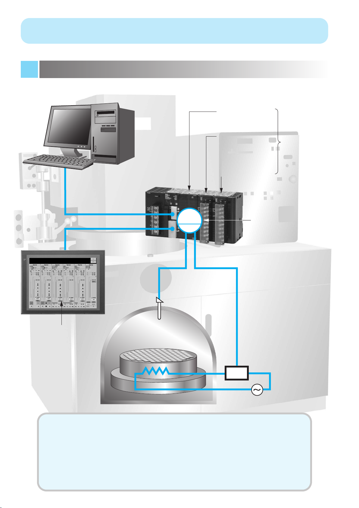
using the following simple system as an example.
System Configuration
CX-Process Tool
(Support Software)
CJ-series Loop-control
CPU Unit
CJ1G-CPU45P
Isolated-type Thermocouple Input Unit
CJ1W-PTS51
Analog Output Unit
CJ1W-DA041
Cable (2 m) for
Peripheral Bus (Toolbus)
CS1W-CN226
Note: The Loop
Controller itself does not
have analog
I/O. Therefore,
PLC CPU Bus
Units must be
used.
NS-series PT
(Touch Panel)
NS12
Screen for Loop Controller
RS-232C Cable
XW2Z-200T (2 m)
Temperature sensor
Type K thermocouple
PID
Input 1 Output 1
4 to 20 mA
Refer to Creating Function
Block Data on the
following page.
Thyristor Unit
(Power Controller)
G3PX
SCR
● This system controls one loop.
- A type K thermocouple is used for the temperature sensor input.
- The temperature range is 0.0 to 500.0°C.
-
The output is 4 to 20 mA and heater control is performed using a Thyristor Unit (Power Controller).
- Continuous proportional PID is set.
Note: The default operation cycle (1 s) is used.
●
The screen for the Loop Controller is displayed by connecting a NS-series PT (Touch Panel).
Page 7
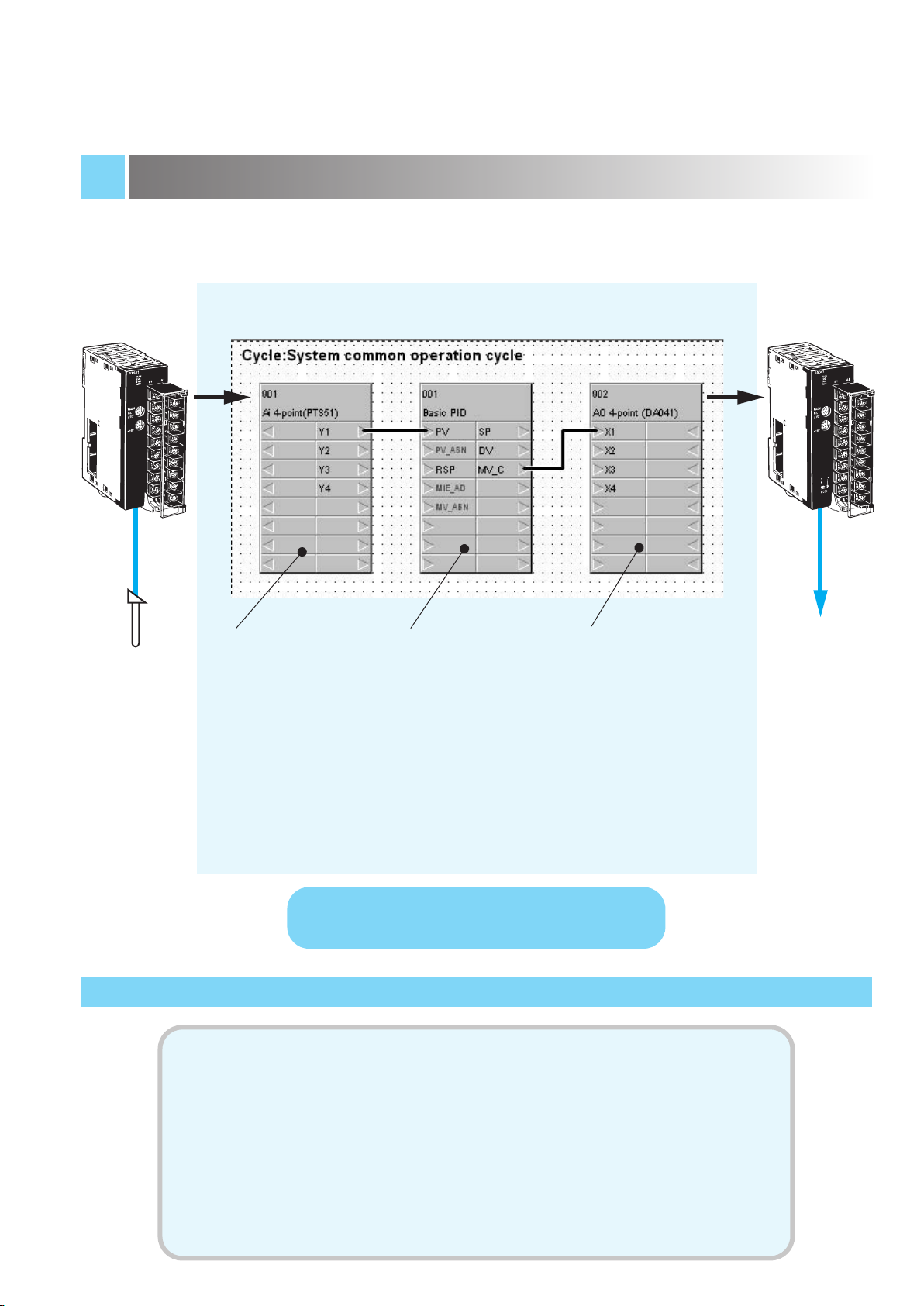
Creating Function Block Data
Thermocouple
Input Unit
CJ1W-PTS51
Type K
thermocouple
Function Block Data
Field Terminal Block for
Analog Input (Isolated
Ai 4-point Terminal
(PTS51)) (Block Model
566)
Inputs the analog signal
from the CJ1W-PTS51.
Control Block for PID
Control (Basic PID)
(Block Model 011)
Performs PID
calculations.
Field Terminal Block for
Analog Output (Ao 4point Terminal (DA041)
(Block Model 587)
Outputs the analog
signal from the CJ1WDA041.
Analog Output Unit
CJ1W-DA041
4 to 20 mA
Loop Controller
(in CJ-series CJ1G-CPU45P Loop-control CPU Unit)
To simplify descriptions, operations for startup settings at the PLC
(such as creating I/O tables (see note) and setting DM Area words
allocated to Analog I/O Units) is not included in the following
description of operations for the CX-Process Tool. Be sure to
separately make the settings using the CX-Programmer.
Note: With CJ-series Loop-control CPU Units, I/O tables can be automatically generated
based on the mounted Units when the power supply is turned ON without
performing the operation to create I/O tables. (With CS-series CPU Units, an
operation must be performed to create the I/O tables.)
Page 8

Page 9

Creating Simple
Function Block Data
for the Loop
Controller
This section presents the flow of operations for
starting the CX-Process Tool (Support
Software), inputting the thermocouple, creating
function block data for one PID loop with an
output of 4 to 20 mA, downloading the data to
the Loop Controller, tuning PID control, and
saving files.
1-1
Page 10
Creating Simple Function Block Data for
the Loop Controller
1
2
Starting the CX-Process Tool/Making a New Project
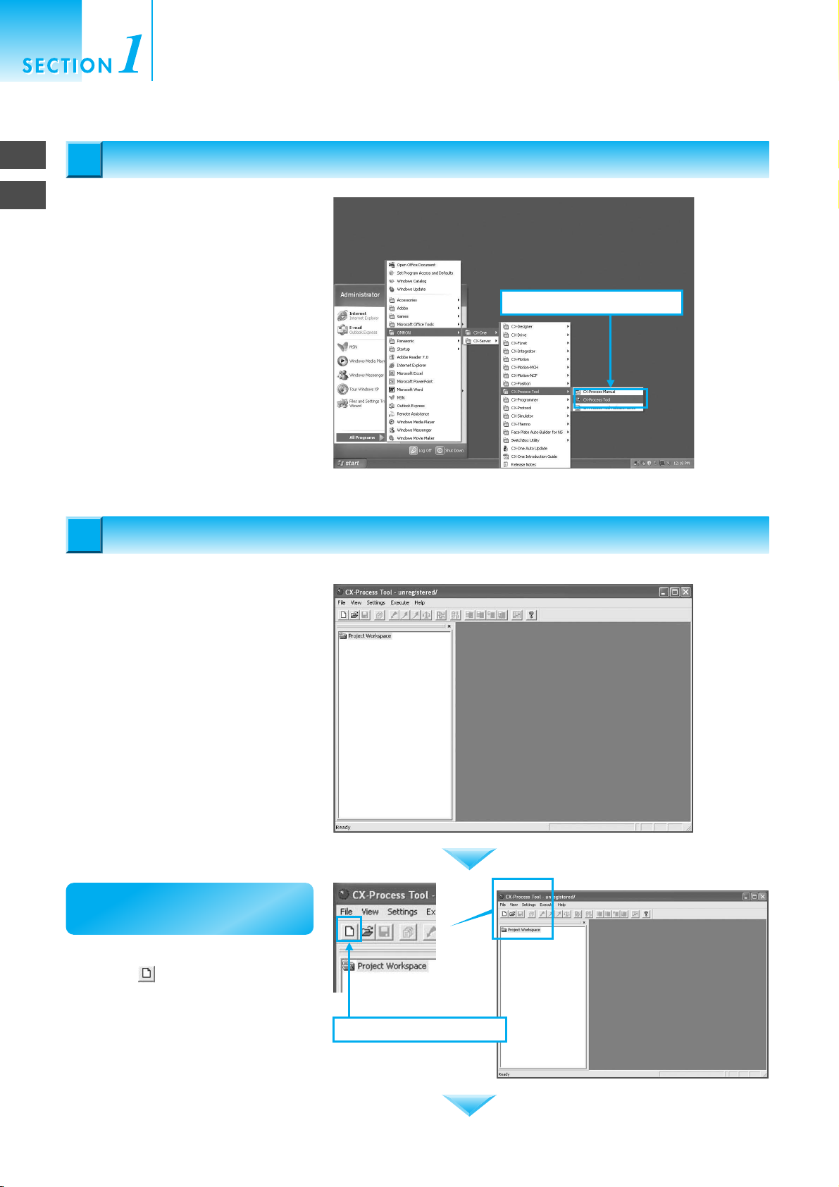
Starting the CX-Process Tool
Starting the CX-Process Tool
1
1
From the Start Menu, select All
Programs - OMRON - CX-One - CXProcess Tool - CX-Process Tool to
start the CX-Process Tool.
Making a New Project
Making a New Project
2
2
1. Select CX-Process Tool.
The window at the right will open when
the CX-Process Tool starts.
First, make a project.
Click the Make a New Function Block
File Button to make a new project.
1-2
2-1. Make a new project.
Page 11
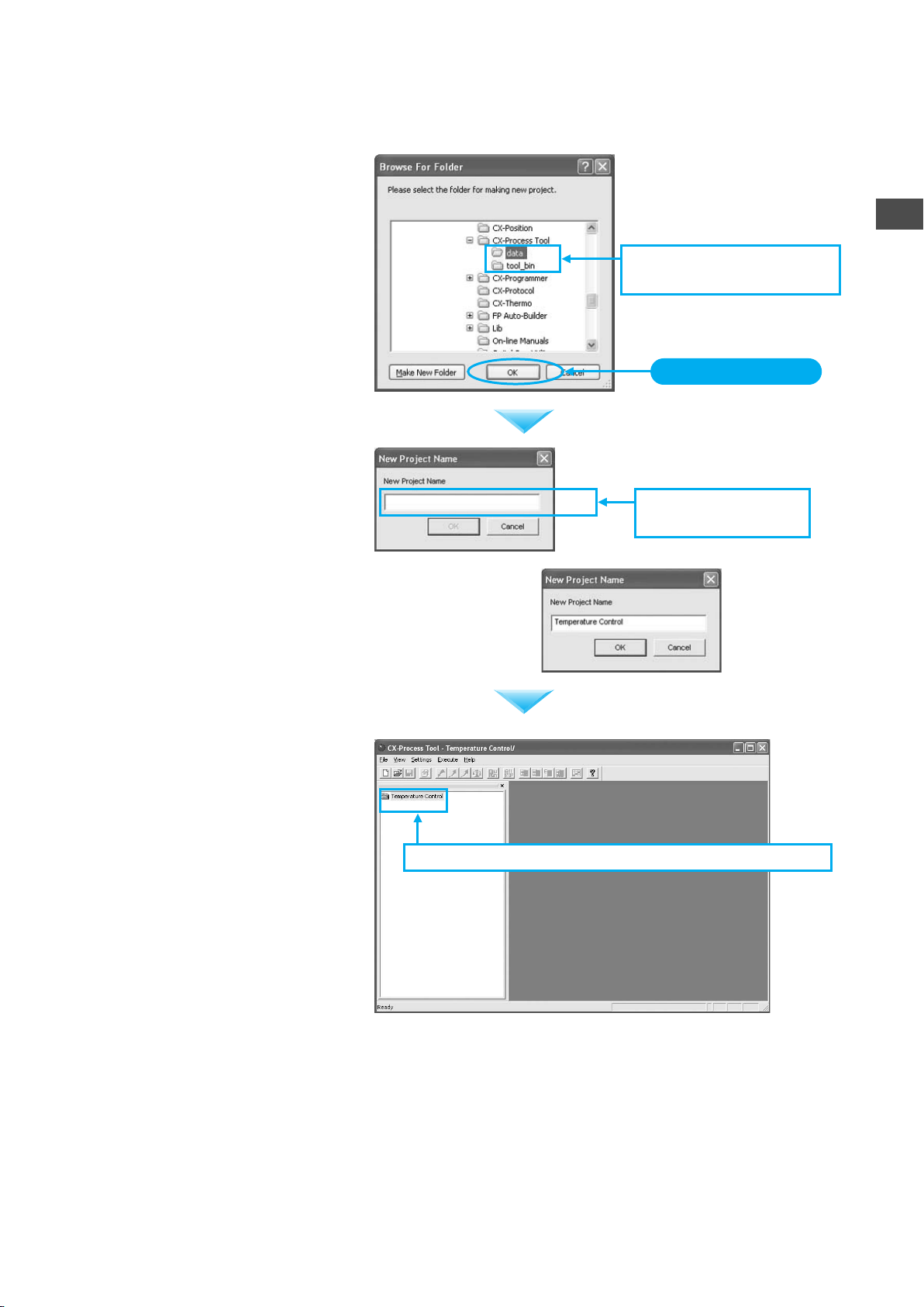
Select a folder in which to save the
data, and then click the OK Button.
The window at the right will open when
the OK Button is pressed. Enter the
project name.
● For example, enter
"Temperature
Control."
2-2. Select the folder in which
to save the data.
Click the OK Button.
2-3. Enter the project
name.
2
Making a New Project
The folder in which the project name
was entered (called the project folder)
will be created in the window on the left
(called the project workspace).
2-4. A project folder called "Temperature Control" is created.
1-3
Page 12
Registering the Loop Controller
Registering the Loop Controller
3
3
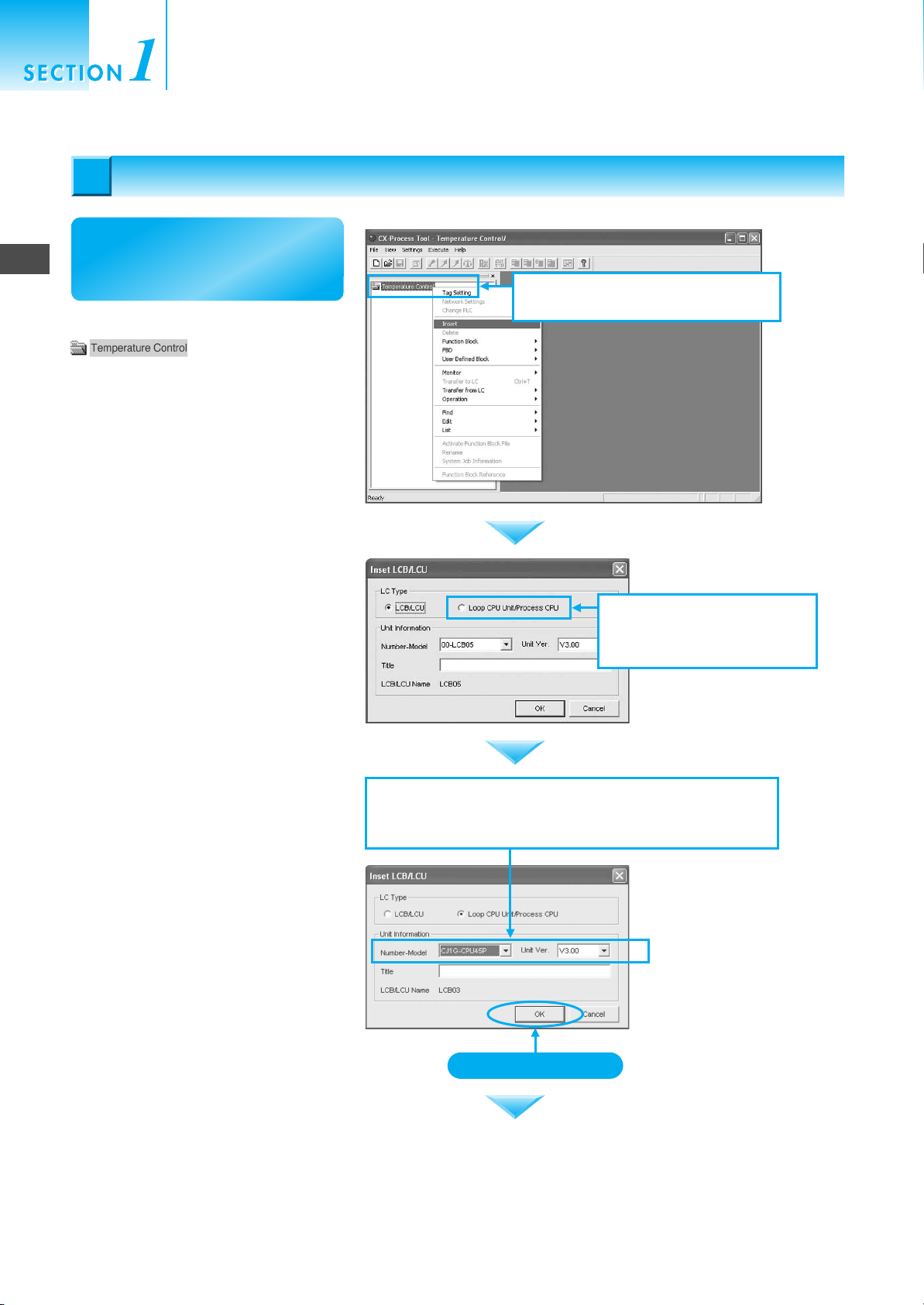
Next, register the Loop
3
Registering the Loop Controller
Controller to be used.
Right-click the Project Folder
Creating Simple Function Block Data for
the Loop Controller
3-1. Right-click the Temperature
Control Folder and select Insert.
and select Insert.
A dialog box for selecting the Loop
Controller will open.
The Loop Controller to be used is a
CJ-series Loop-control CPU Unit.
Therefore, first select Loop CPU
Unit/Process Unit for the LC type.
Next, select the model number and
LCB Unit version. The model number
is the CJ1G-CPU45P and the version
is 3.0.
3-2. Select the Loop CPU
Unit/Process CPU Option
for the LC type.
3-3. Select the model number and the LCB Unit version
in the Unit Information Field. Select CJ1G-CPU45P
for the model number and 3.0 for the version.
1-4
Click the OK Button.
Page 13

A node function block file labeled
will be added
under the Temperature Control
Project Folder .
Creating Function Block Data
Creating Function Block Data
4
4
Next, actually create
simple function block data.
3-4. A node function block file will be added
under the Temperature Control Folder.
3
4
Creating Function Block Data
Click the plus sign (+) to the left of the
node function
block file, and then click the plus sign
on the LCU/LCB element folder
underneath it. The tree structure will be
opened.
The window shown on the right will
open when the 04. Block Diagram 1
Folder in the tree is double-clicked.
Paste the following three items into the
Function Block Diagram Window at the
right.
• Function block for analog input:
Isolated Ai 4-point Terminal (PTS51)
• Function block for PID: Basic PID
• Function block for analog output:
Isolated Ao 4-point Terminal (DA041)
4-1. Click the plus signs (+) to
display the tree structure.
4-2. Double-click the 04. Block
Diagram 1 Folder.
Seven folders will be
displayed under the Loop
Controller LCB03 V3.0
Folder: System, Field
Terminal, Sequence
Control, Block Diagram 1,
Block Diagram 2, and
Block Diagram 3.
Maximize
Function block diagrams
can be drawn at this point,
but to increase the area,
click the middle of the
three buttons. The window
will be maximized.
1-5
Page 14

Creating Simple Function Block Data for
the Loop Controller
4
Creating Function Block Data
First, paste the function block Isolated
Ai 4-point Terminal (PTS51) for
analog input. Right-click in the window
at the right. The pop-up menu shown
in the figure at the right will be
displayed. Select Register - Field
Terminal from the menu.
The dialog box shown at the right will
be displayed. Press the Insert Button.
4-3. Paste the function blocks. First, register
the Isolated Ai 4-point Terminal.
4-3-1. Right-click and selected Register -
Field Terminal.
4-3-2. Select 566 Ai 4-point
(PTS51).
A window for the Isolated Ai 4-point
Terminal (PTS51) Block will appear.
Click the Insert Button.
4-3-3. The Isolated Ai 4-point
Terminal Block will appear.
1-6
Page 15

The function block can be moved
without restriction by dragging it with
the mouse.
4-3-4. Move the function block
to the desired location.
4
Creating Function Block Data
Next, paste the Basic PID Block. Just
as in the previous procedure, rightclick and select Register - Control
Block.
A window for selecting the function
block will open. Click the Down-
Arrow .
4-4. Register the Basic PID Block.
4-4-1. Right-click and select
Register - Control Block.
4-4-2. Select the control block.
Click.
Select Basic PID from the function
block names and click the Insert
Button.
4-4-3. Select Basic PID and
click the Insert Button.
1-7
Page 16
Creating Simple Function Block Data for
the Loop Controller
4
5
Connecting Function Blocks
Paste the function block Isolated Ao 4point Terminal (DA041) for analog
output in the same way. Right-click in
the window on the right and select
Register - Field Terminal. Set the
Field Terminal to Ao 4-point (DA041).
This completes pasting the function
blocks.
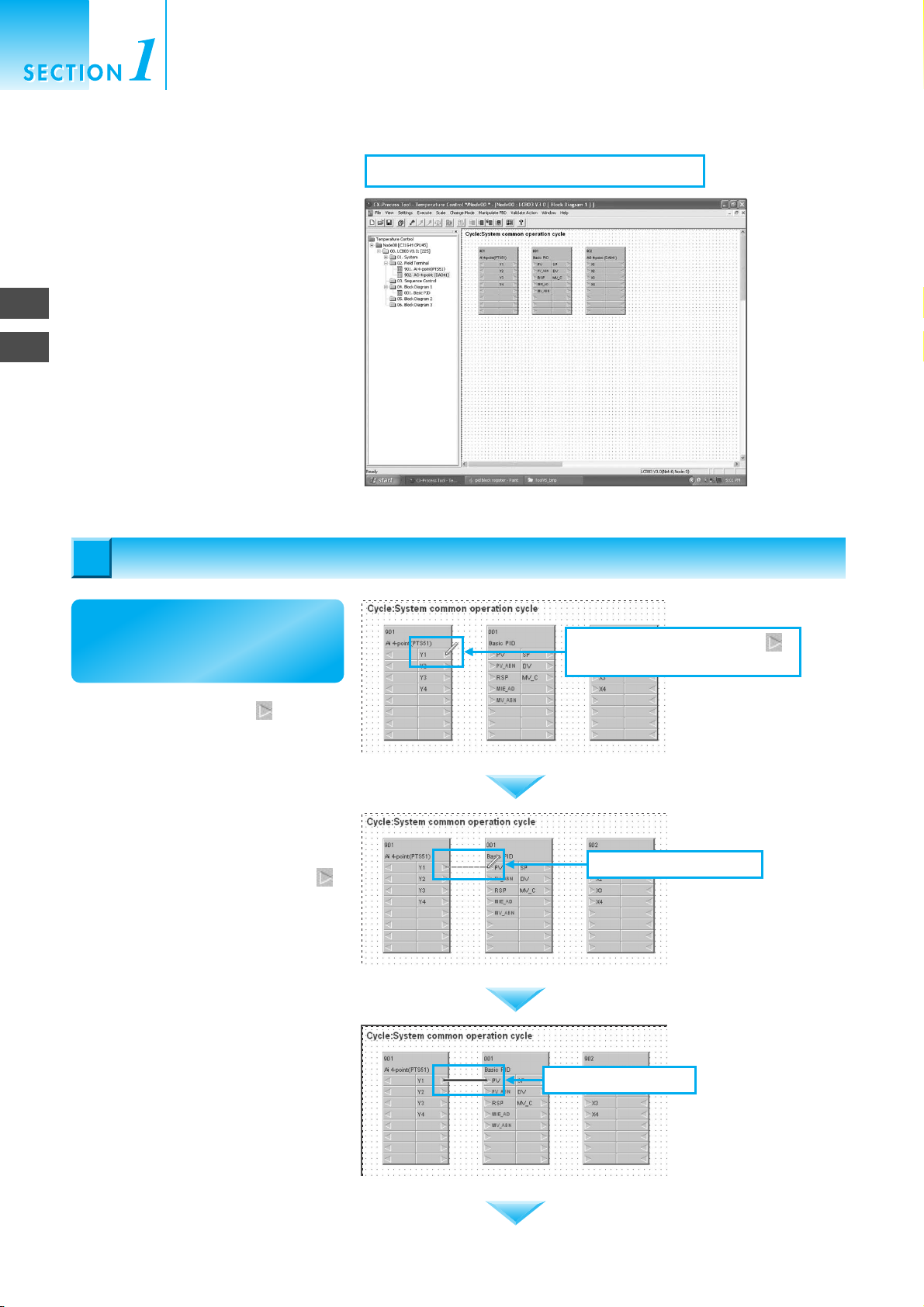
Connecting Function Blocks
Connecting Function Blocks
5
5
4-5. Register the Ao 4-point Terminal (DA041).
Next, connect the function
blocks that were pasted.
First, click the Right Arrow of the
Y1 Terminal of the Ai 4-point (PTS51)
block.
Drag the mouse to the PV Terminal
of the Basic PID Block and double-click.
5-1-1. Click the Right Arrow
of the Y Terminal.
5-1-2. Drag the mouse.
1-8
5-1-3. Double-click.
Page 17
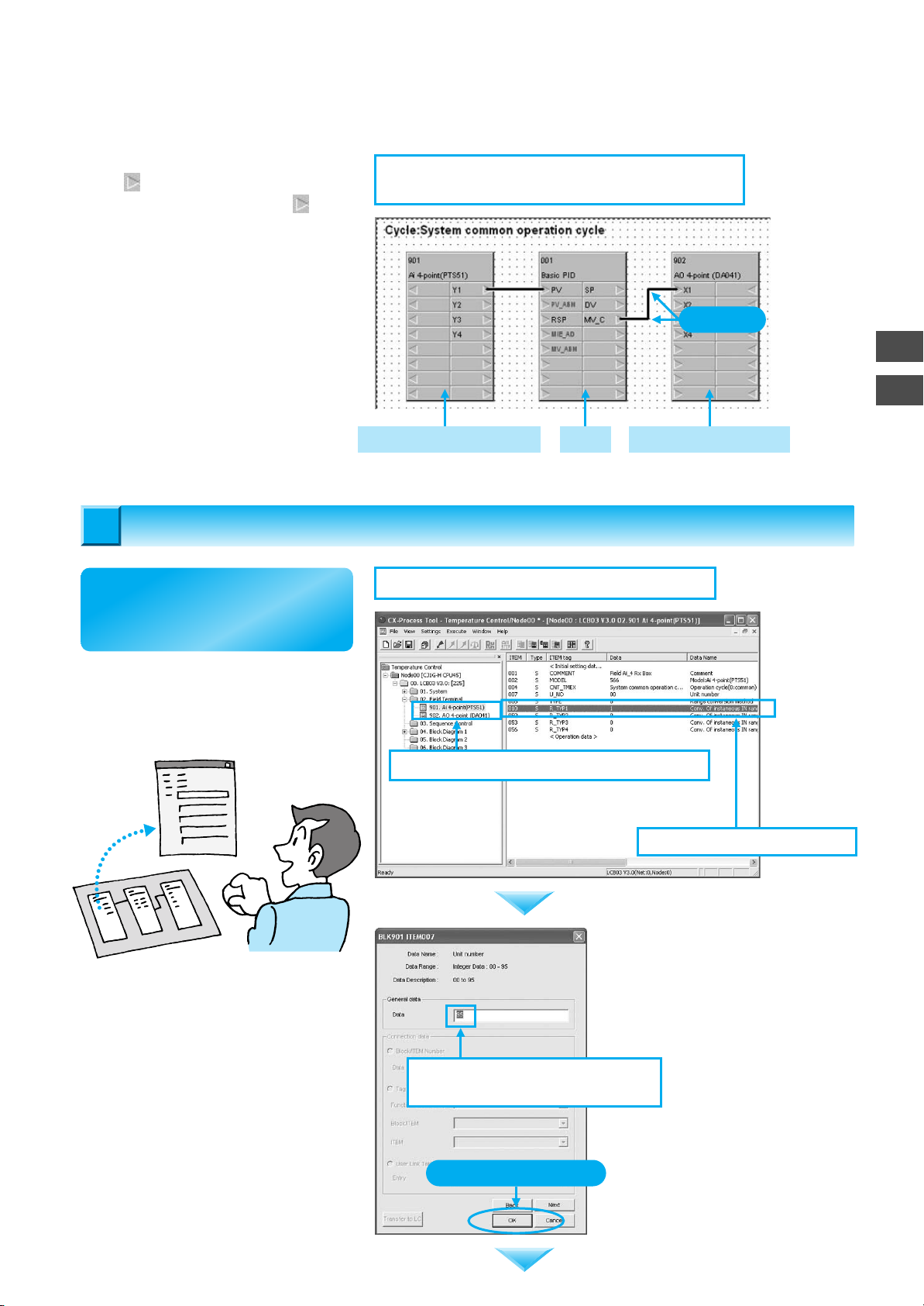
In the same way, connect the Right
Arrow of the MV_C Terminal for
Basic PID with the Right Arrow for
the X1 Terminal of Ao 4-point (DA041).
Set ITEMs for Function Blocks
Set ITEMs for Function Blocks
6
6
5-2. Connect the Basic PID block to the Ao 4-point
Terminal (DA041).
Click.
Thermocouple Input Unit PID Analog Output Unit
5
6
Set ITEMs for Function Blocks
Next, make settings so that
the pasted function blocks
can be used.
Double-click 901. Ai 4-point (PTS51)
in the tree in the window on the left.
The details of the function block will
be displayed in the window on the
right.
6-1. Setting the Function Block for Analog Input
6-1-1. Double-click 901. Ai 4-point (PTS51).
6-1-2. Double-click ITEM 007.
First, change the unit number. Doubleclick ITEM 007 in the window on the
right. The window shown at the right will
be displayed.
The unit number is currently set to "95."
Set the unit number to be used (00) and
press the OK Button.
6-1-3. Set ITEM 007 (Unit Number)
to 00.
Click the OK Button.
1-9
Page 18
Creating Simple Function Block Data for
the Loop Controller
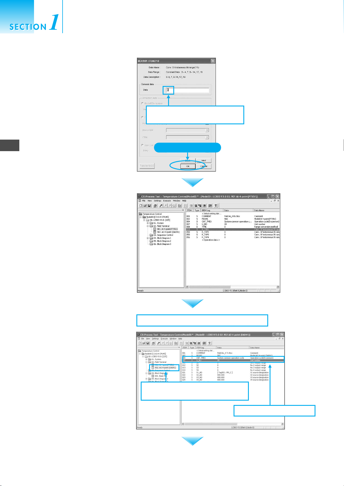
Double-click ITEM 010 to use Input 1.
Next, because a type K thermocouple
is being used and the input range is
0.0 to 500.0°C, change Data to 1 and
click the OK Button.
Note: The input type setting (i.e., parameter) for the
CJ1W-PTS51 Isolated-type Thermocouple
Input Unit must be set to a type K
thermocouple (decimal point) = 0001 hex as
given below:
DM Area Word Allocated in the CPU Unit
6
Set ITEMs for Function Blocks
D20019 = 0001 hex
(When the unit number is 0.)
(It is not necessary to know the address if the setting
is made by editing parameters by double-clicking
CJ1W-PTS51 in the I/O tables in the CXProgrammer.)
The ITEM Setting Window will close.
Confirm that the settings have
changed.
6-1-4. Set ITEM 010 (Input Range)
to 1.
Click the OK Button.
1-10
Next, double-click 902. Ao 4-point
(DA041) in the tree in the window on
the left. Change the unit number in the
same way as above.
Double-click ITEM 007 in the window
on the right.
6-2. Setting the Function Block for Analog Output
6-2-1. Double-click 902. Ao 4-point
(DA041).
6-2-2. Double-click ITEM 007.
Page 19
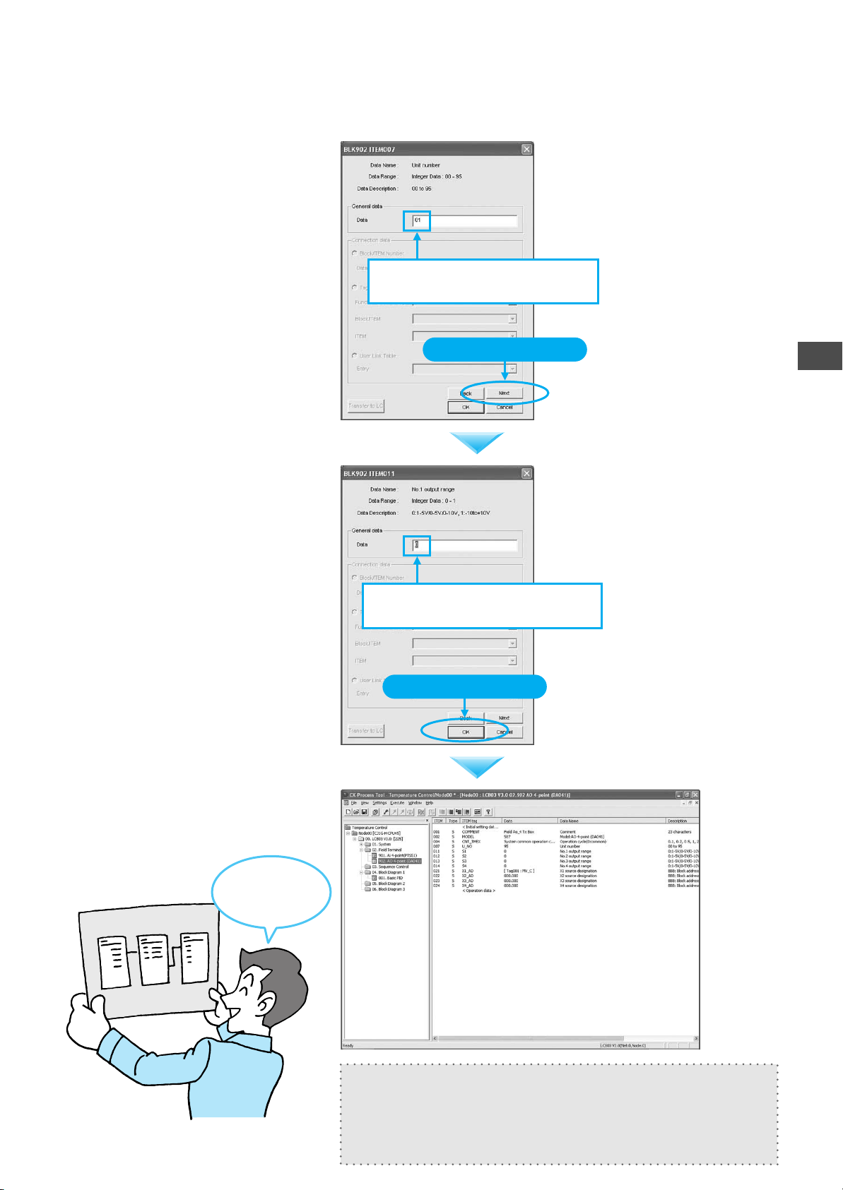
The unit number is currently set to
"95." Set the unit number to be used
(01) and press the Next Button.
6-2-3. Set ITEM 007 (Unit Number)
to 01.
An output of 4 to 20 mA is used for the
system. To keep Output 1 the same
as the default setting of 0, simply
press the OK Button. The window will
close.
Note: Analog Output Unit
The output range setting (parameter) for the
CJ1W-DA041 must be set to 1 to 5 V/4 to
20 mA = 0002 hex as listed below:
DM Area Word Allocated in the CPU Unit
D20101 = 0002 Hex
(When the unit number is 1 and Output 1 is
used)
(It is not necessary to know the address if the setting
is made by editing parameters by double-clicking
CJ1W-DA041 in the I/O tables in the CXProgrammer.)
Click the Next Button.
6-2-4. Set ITEM 011 (Input Range)
to 0.
Click the OK Button.
6
Set ITEMs for Function Blocks
This completes pasting function
blocks, connecting function blocks,
and setting ITEMs.
I made the
function block
Thermocouple
Input Unit
PID
Analog
Output Unit
data!
In this example, the operation cycle is set to 1 s for the entire system
and the start mode is set to a hot start (i.e., operation starts with the
auto/manual status held immediately before the power supply was
turned OFF.) Therefore, System Common block is used at its default
values.
1-11
Page 20
Creating Simple Function Block Data for
the Loop Controller
Communications Settings between Computer and PLC
Communications Settings between Computer and PLC
7
7
7
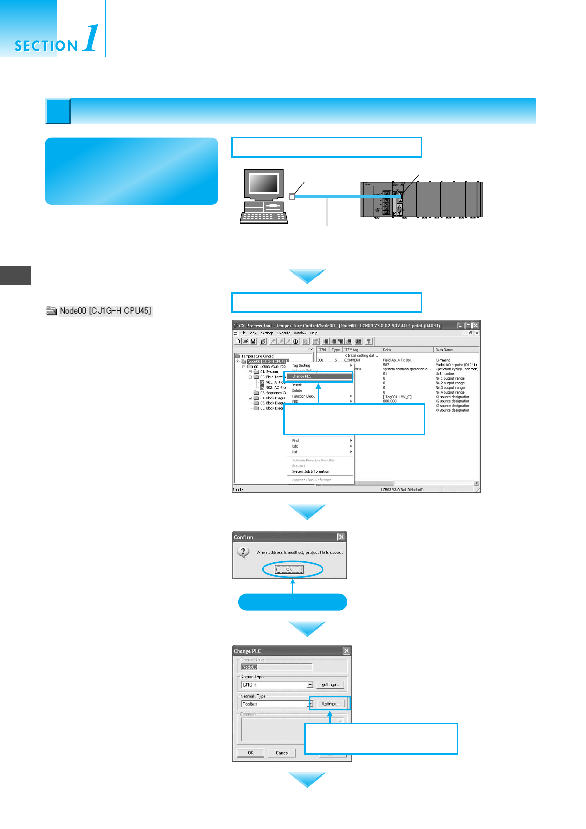
Communications Settings between Computer and PLC
Next, connect the computer and
the PLC with a cable and make
the communications settings to
enable sending the function
blocks to the Loop Controller.
Connect the computer to the PLC at
the peripheral port using a Peripheral
Port Connecting Cable.
Right-click Node00[CJ1G-H CPU45]
in the tree in
the window on the left to set the
communications port and select
Change PLC from the pop-up menu.
7-1. Connect the cable.
RS-232C
IBM PC/AT or
compatible
(9-pin RS-232C)
7-2. Setting Communications Conditions
7-2-1. Right-click and select
CS1W-CN226/626
Peripheral Port
Connecting Cable
Change PLC.
Peripheral port
1-12
A dialog box will open. Click the OK
Button.
Click the OK Button.
The Change PLC Window will open.
Click the Settings Button.
7-2-2. Click the Settings Button in
the Change PLC Window.
Page 21
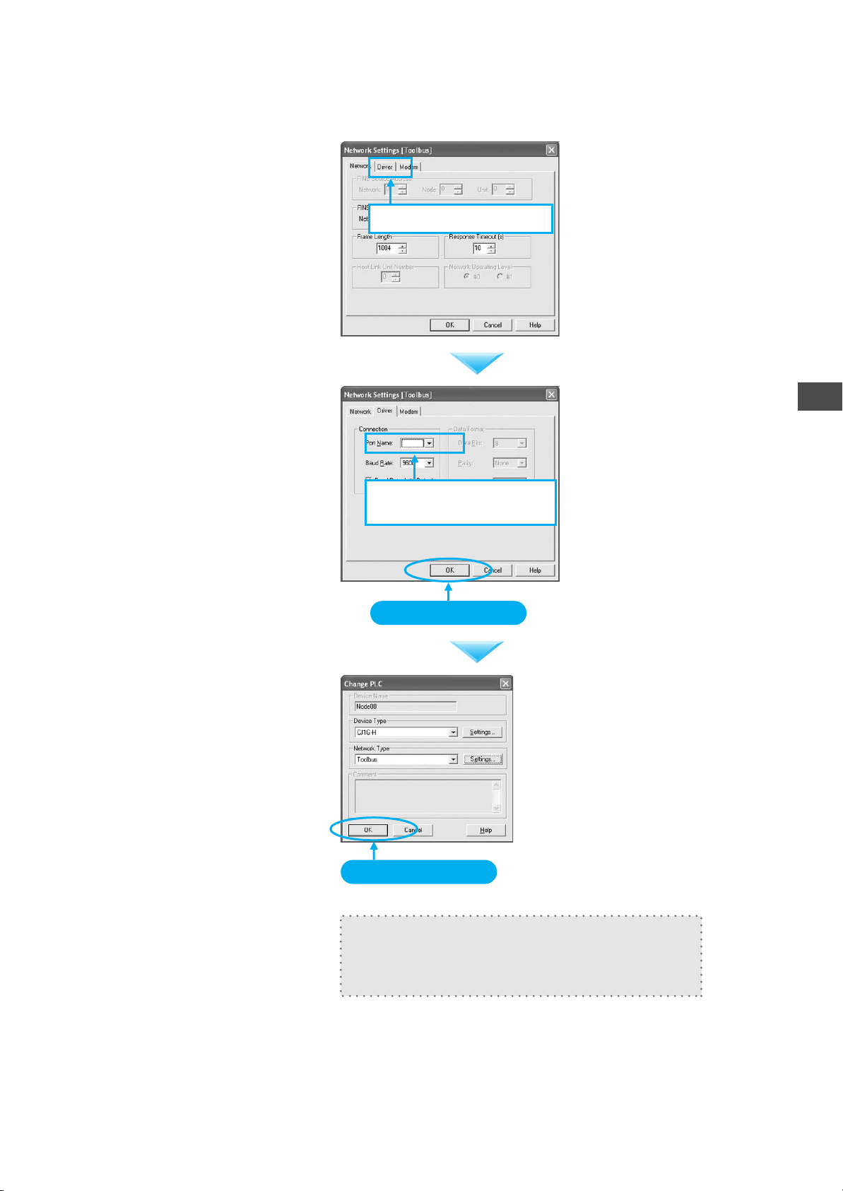
The Network Settings [Toolbus]
Window will open. Click the Driver
Tab.
7-2-3. Click the Driver Tab.
Set the Port Name to the actual port to
be used, and then click the OK Button
to close the window.
The communications setting will be
completed once the OK Button is
clicked once again.
7-2-4. Set the COM port for
the computer.
Click the OK Button.
7
Communications Settings between Computer and PLC
Click the OK Button.
With the CX-Process Tool, an online connection
will be made automatically when online operations,
such as downloading, are performed after making
the communications settings described above.
1-13
Page 22
8
Transferring Function Block Data to the Loop Controller
Creating Simple Function Block Data for
the Loop Controller
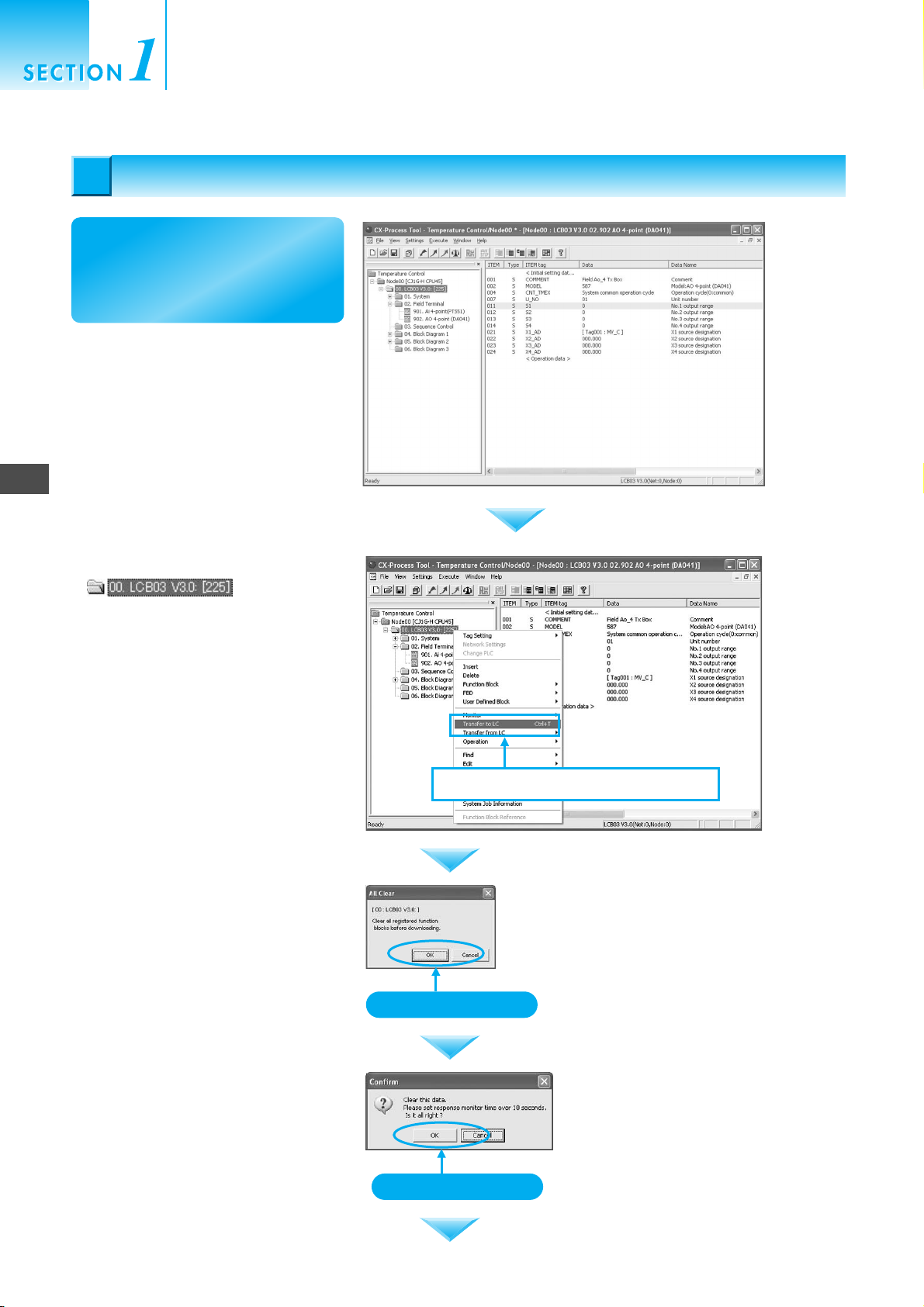
Transferring Function Block Data to the Loop Controller
Transferring Function Block Data to the Loop Controller
8
8
Now that communications
settings have been completed,
transfer the function block data
to the Loop Controller.
Right-click
on the tree in
the window at the left and select
Transfer to LC from the pop-up
menu.
Click the OK Button.
Right-click and select Transfer to LC .
Click the OK Button.
1-14
Click the OK Button.
Page 23
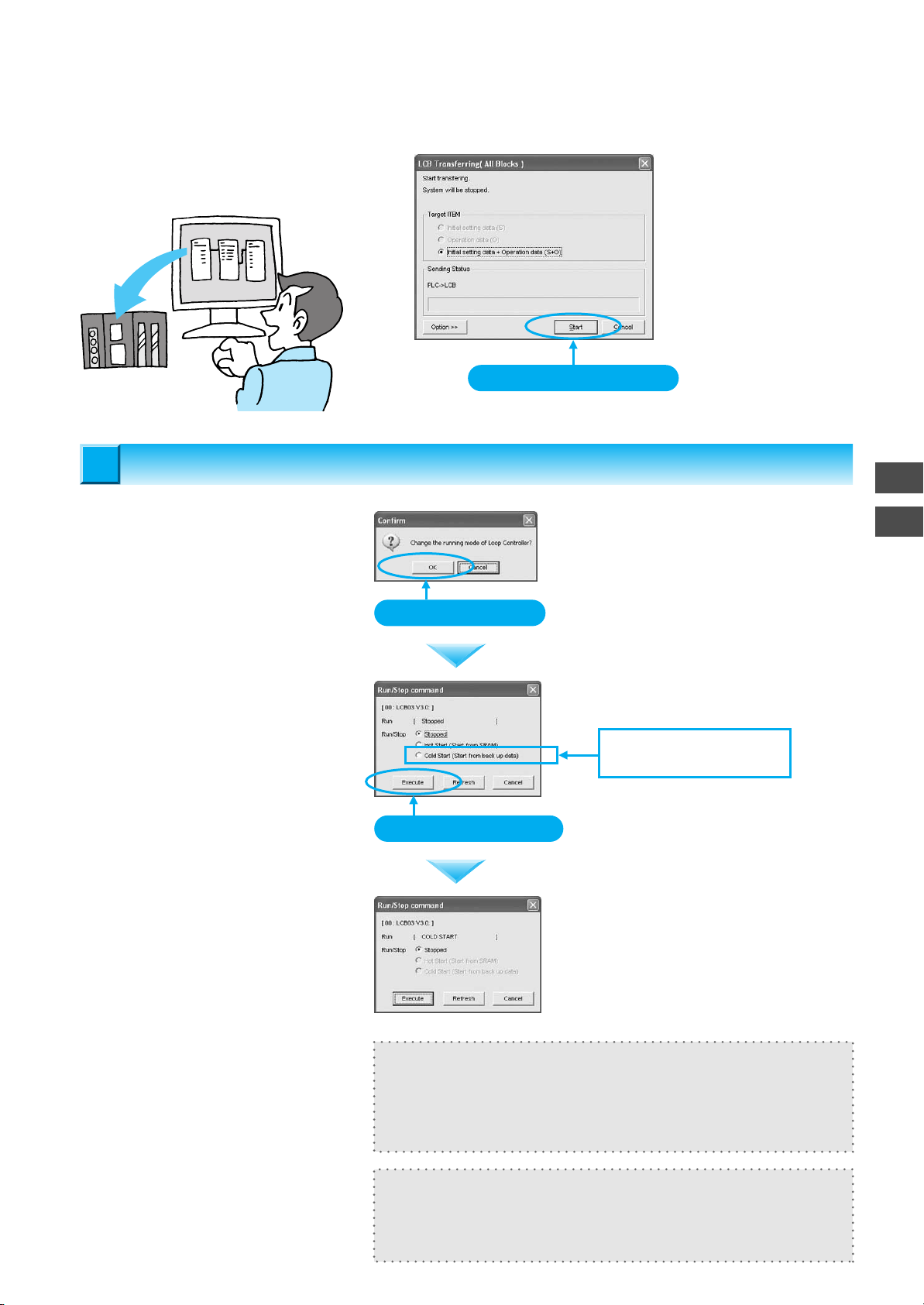
Click the Start Button. The window
will automatically close when the
download has been completed.
Downloading
Downloading
Function
block data
Loop Controller
Starting Operation
Starting Operation
9
9
The window to start transferring will be
displayed continuing with the transfer
operation. Click the OK Button.
Select Cold Start and click the
Execute Button.
Click the Start Button.
Click the OK Button.
Select Cold Start for the
Run/Stop Command.
8
9
Starting Operation
The operation status display will
change to Cold Start when operation
has been started.
Click the Execute Button.
In this example, the operation is started right after downloading, but
operation can also be started by using an operation command from the
menu, or operation automatically when the power is turned ON (but a
hot start will be used by default).
Use Hot Start to hold the manipulated variable (MV) and other settings
from immediately before a momentary stop. Otherwise, normally use
Cold Start.
1-15
Page 24
Creating Simple Function Block Data for
the Loop Controller
PID Tuning
10
PID Tuning
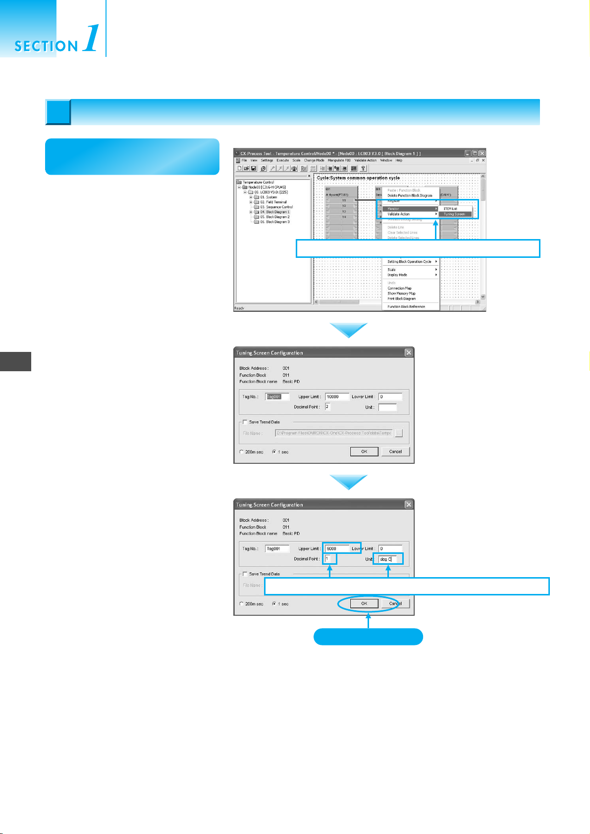
10
Tune PID constants for the
Basic PID Block.
Right-click the Basic PID Block and
select Monitor - Tuning Screen from
the pop-up menu.
10-1. Right-click and select Monitor - Tuning Screen.
10
PID Tuning
The Tuning Screen Configuration
Window will open. At this point, set the
tuning screen.
For the system configuration specified
at the beginning of this guide, the
temperature range is to be set to 0.0
to 500.0°C. Therefore, input 5000 for
the Upper Limit, 1 for the Decimal
Point, and deg C for the Unit. When
finished, click the OK Button.
10-2.
Set the temperature range in the Tuning Screen Configuration Window.
Click the OK Button.
1-16
Page 25
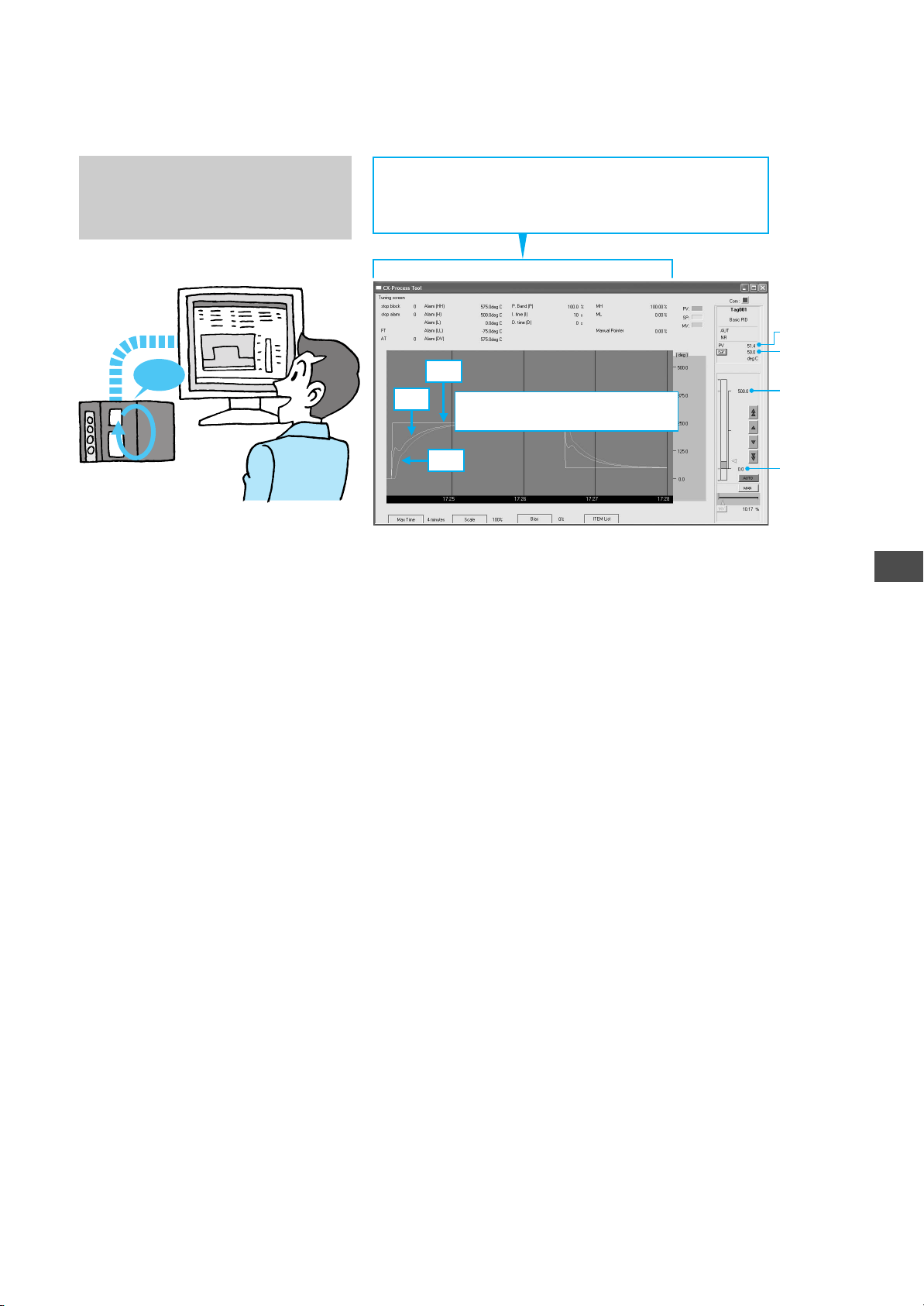
The window shown at the right will not
be displayed if the PLC is not actually
connected. The window, however, is
included here as reference.
PID tuning
Operation
Clicking on a setting name will display a dialog box to
change the setting. Change the setting with the 10-key pad
dialog box (using the mouse) or by using the keyboard.
SP
MV
The window will be displayed and
then trend data will be displayed.
PV
SP
Upper limit
Loop Controller
PV
Lower limit
10
PID Tuning
1-17
Page 26

Creating Simple Function Block Data for
the Loop Controller
Reference Information
10
PID Tuning
● Autotuning (AT)
● Fine Tuning (FT)
Autotuning is provided as a convenient means for tuning PID control.
To perform autotuning, click the AT Button. The PID constants will be
tuned when autotuning is started.
The following figure shows an example of AT execution and the response of the subsequent temperature control loop. Compared with
the response example on the previous page, temperature settings are
changed faster.
Execute fine tuning (FT) when the control performance produced by
autotuning is not acceptable, when autotuning produces instability in
the PV, or when interruption of control cannot be allowed.
Fine tuning improves control by automatically setting PID constants
using three user settings listed below along with fuzzy logic applied to
the previous control conditions.
• Hunting
• Overshooting
• Responsiveness
Either one or two of the user settings can be set to any of five adjustment levels. For example, to improve control responsiveness and
overshooting, the Responsiveness and Hunting parameters can be
set to the desired levels.
1-18
Page 27

Uploading and Saving Function Block Data
11
11
Uploading and Saving Function Block Data
Upload the data from the actual
Loop Controller and save the
data in a file.
Upload the parameters (e.g., PID constants) tuned in the actual Loop Controller to the computer. Right-click
in the tree in the
window on the left and select Transfer
from LC - Previous.
Click the OK Button.
11-1. Upload the data from the actual Loop Controller.
11-1-1. Right-click and select Transfer from LC - Previous.
11
Uploading and Saving Function Block Data
Click the Start Button.
Transferring the setting parameters
from the Loop Controller to the computer will begin. The window will close
when the transfer has been completed.
Click the Save Button on the toolbar
to save the function block data.
Tuned function
block data
Uploading
Uploading
Click the OK Button.
11-1-2. Start the transfer.
11-2. Save the function block data.
Saving data
Loop Controller
1-19
Page 28

Page 29

Making the NS-series
PT Screen for the
Loop Controller
This section describes the operational flow
from using the Face Plate Auto-Builder for NS
to automatically generate the NS-series PT
screen for the Loop Controller based on the
function block data that was created, up to
displaying the screen on the CX-Designer
(Screen Creation Support Software for NSseries PTs).
2-1
Page 30

Making the NS-series PT Screen
for the Loop Controller
1
2
CSV tags must be set in advance (i.e.,
Setting the CSV Tags in Advance/Automatically Creating the NS-series PT Screen for the Loop Controller
before creating the NS-series PT
screen for the Loop Controller).
Right-click 001.Basic PID in the tree in
the window on the left and select Tab
Setting - CSV Tag from the pop-up
menu.
Input the Scaling Upper Limit, Scaling
Lower Limit, DP (i.e., decimal point
position), and Unit. Click the OK
Button.
Setting the CSV Tags in Advance
Setting the CSV Tags in Advance
1
1
1-1. Right-click 001.Basic PID and select Tab Setting -
CSV Tag.
Automatically Creating the NS-series PT Screen for the Loop Controller
Automatically Creating the NS-series PT Screen for the Loop Controller
2
2
Automatically create the NS-series PT
screen for the Loop Controller.
Start the Face Plate Auto-Builder for
NS (NSFP) and the project for the CXDesigner will be generated
automatically.
Select Execute - Create Tag File -
Start NSFP from the menu.
I can make it
all by myself!
Click the OK Button.
2-1. Start the Face Plate Auto-Builder for NS (NSFP)
at the same time as creating tag files.
2-1-1. Select Execute - Create Tag File -
Start NSFP.
2-2
Page 31

Click the OK Button.
Click the OK Button. The following
window will be displayed.
2-2. Compile the tags.
Click the OK Button.
Click the OK Button.
2
Automatically Creating the NS-series PT Screen for the Loop Controller
Click the OK Button.
Give the file a name (in this case,
TagList) and click the Save Button.
Click the OK Button.
The Face Plate Auto-Builder for NS will
start.
Click the OK Button.
Click the Save Button.
Click the OK Button.
2-3
Page 32
Making the NS-series PT Screen
for the Loop Controller
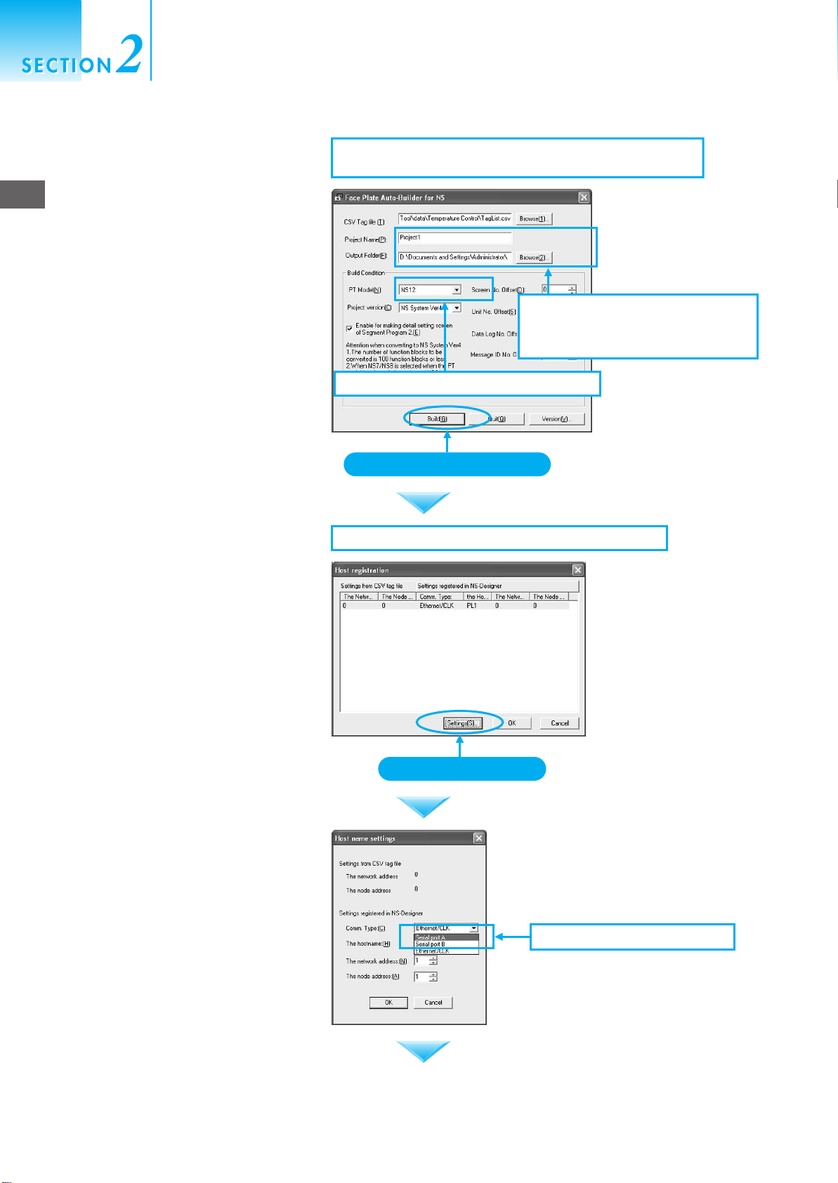
Name the project and click the Browse
(2) Button. Set the output folder, set NS
12 for the PT Model, and click the
2
Automatically Creating the NS-series PT Screen for the Loop Controller
Build Button.
Register the host (i.e., host registration
in CX-Designer project) so that the NSseries PT and the PLC can
communicate. When the window is
displayed, click the Settings Button.
2-3. The project for the CX-Designer will be automatically
generated when the Build Button is clicked.
2-3-2. Select NS12 for the PT Model.
Click the Build Button.
2-4. Registering the host in the CX-Designer project.
2-3-1. Give the project a name. Click
the Browse (2) Button and
select the folder to save in.
2-4
Click the Settings Button.
Select Serial Port A for Comm. Type.
2-4-1. Select Serial Port A.
Page 33
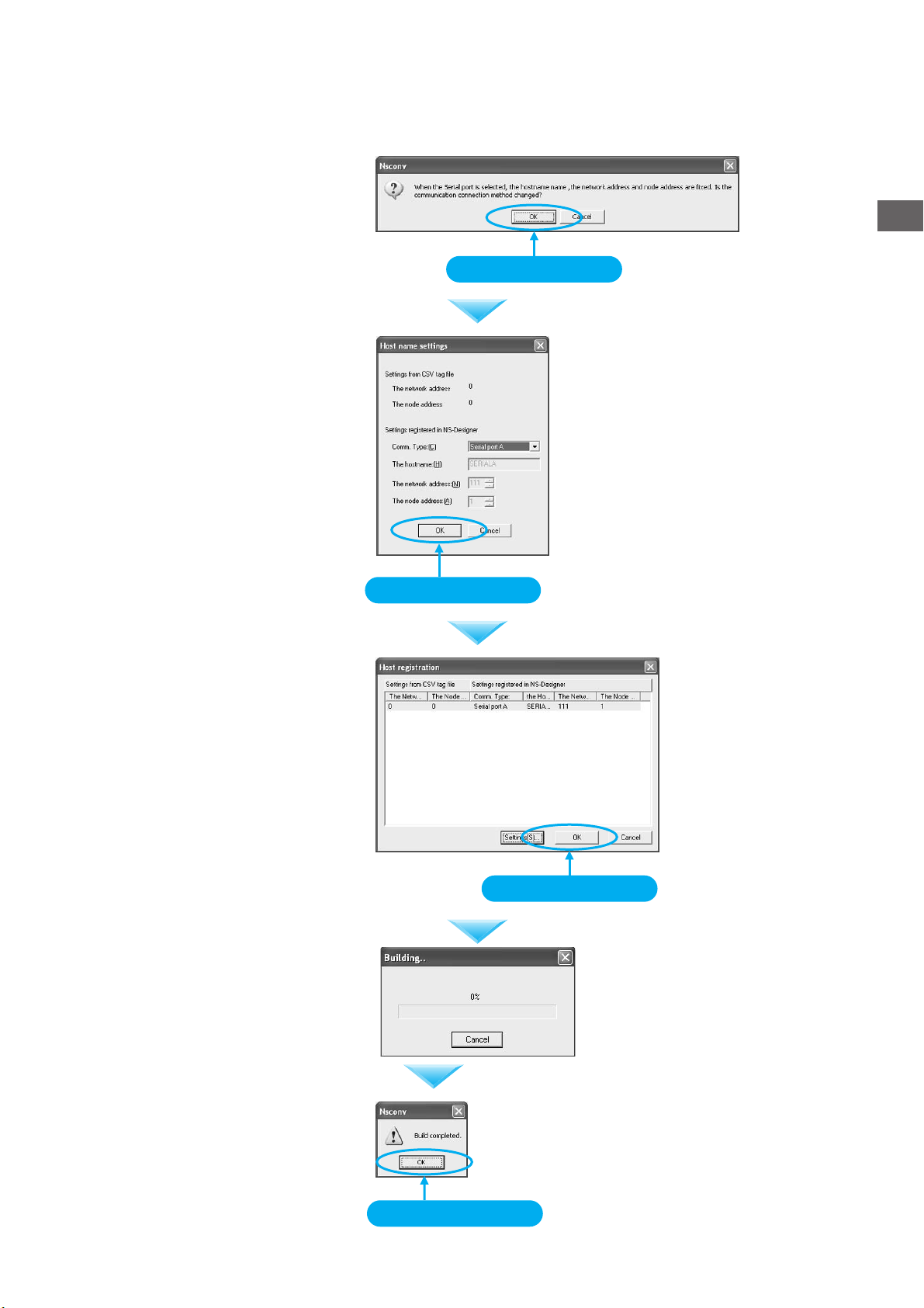
Click the OK Button.
Click the OK Button.
Click the OK Button.
Click the OK Button.
2
Automatically Creating the NS-series PT Screen for the Loop Controller
Click the OK Button.
A progress dialog box will be displayed.
A message saying that building has
been completed will be displayed. Click
the OK Button.
Click the OK Button.
Click the OK Button.
2-5
Page 34
Making the NS-series PT Screen
for the Loop Controller
Displaying the NS-series PT Screen for the Loop Controller
Displaying the NS-series PT Screen for the Loop Controller
3
3
Display the NS-series PT screen for the
Loop Controller.
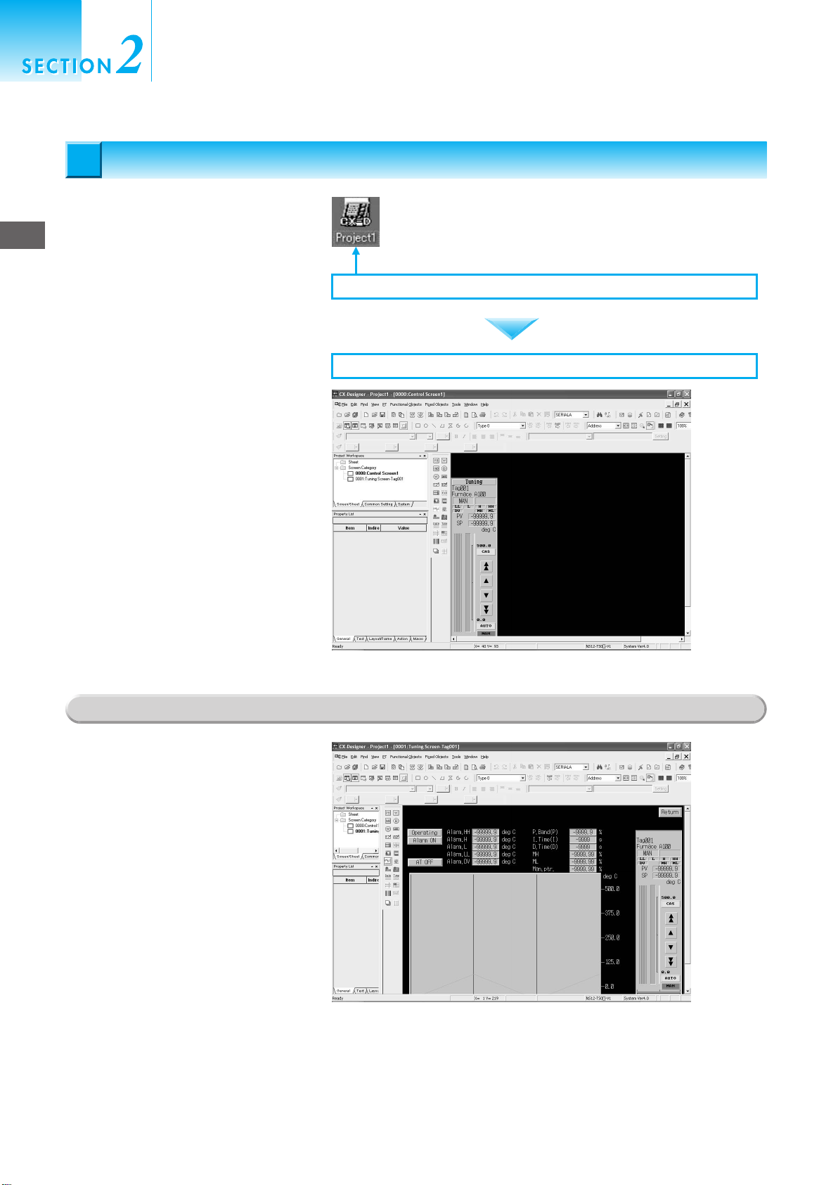
3
Double-click the automatically created
Displaying the NS-series PT Screen for the Loop Controller
project file (with the name given above)
for the CX-Designer. The CX-Designer
will start.
3-1. Double-click the CX-Designer project file.
The generated faceplate can be
checked by selecting items on the
screen.
Reference Information
The trend screen that is created can be
checked by selecting items on the
screen.
3-2. The screen for the Loop Controller is generated automatically.
2-6
Page 35

Useful
Functions
Page 36
Useful Functions
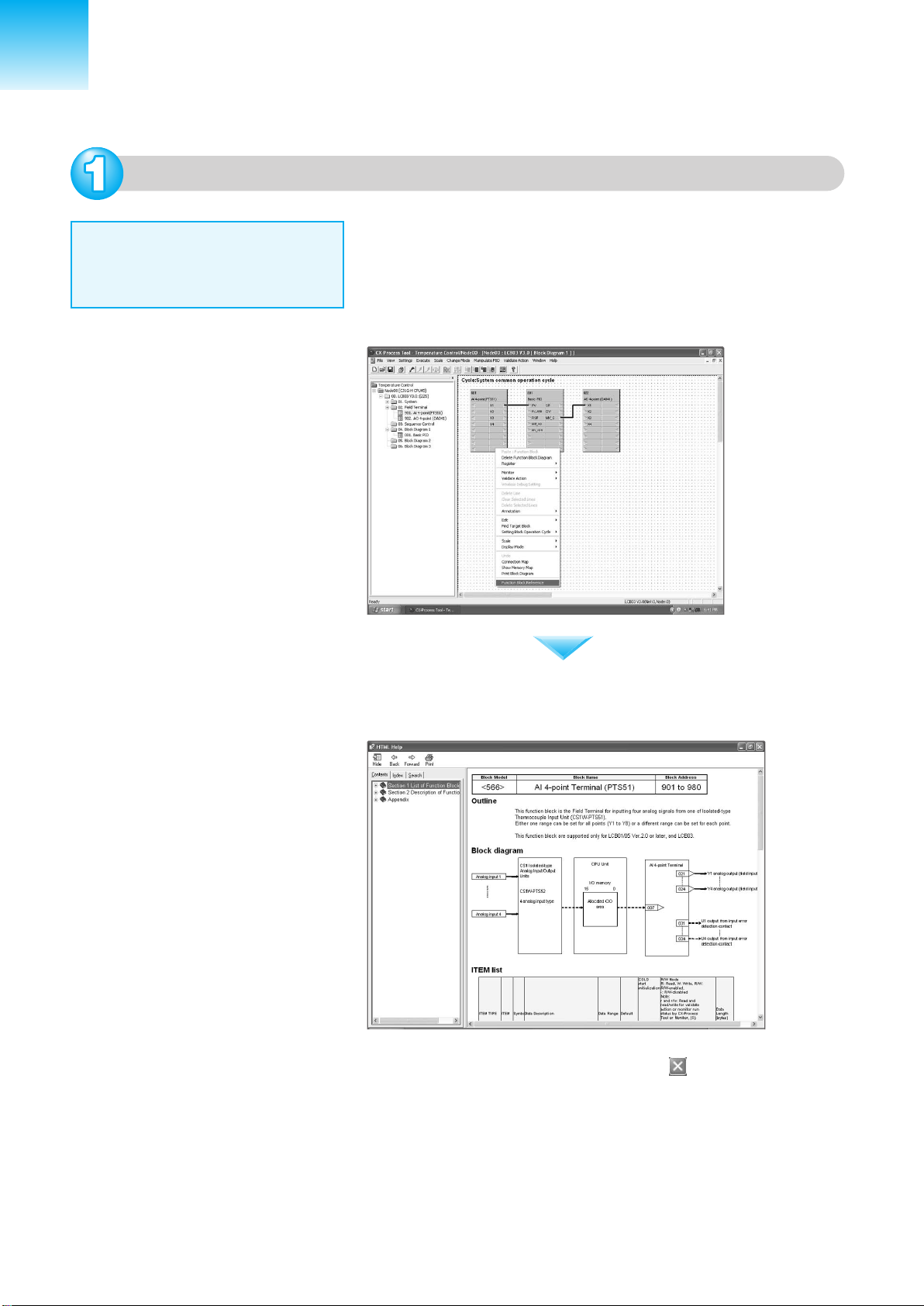
Viewing the Online Manual
The online manual is useful to find
proper settings, such as for setting
ITEMs in function blocks.
To view the online manual, double-click 04. Block Diagram 1 in the
tree in the window on the left. A block diagram will be displayed.
Next, right-click the function block you want to find information about
(in this case, Isolated Ai 4-point Terminal). A menu will be displayed.
Click Function Block reference at the bottom of the menu.
The online manual will open and the function block will be explained.
This explanation may be useful for reference.
To close the window, click the Close Button at the upper right of
the window.
Page 37
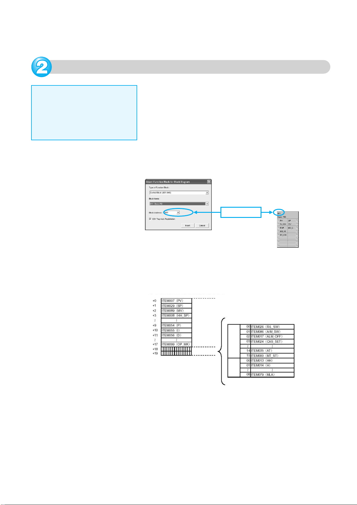
HMI Function
This function automatically assigns
function block data (e.g., PV, SP,
and MV) in order of function block address to addresses in the specified
bank in the EM Area of the CPU Unit
as a constant data conversion area.
The HMI function is set in the System Common Block (Block Model
000). By default, the refresh cycle in EM0 is set to 1 s. The blocks
that are allocated are determined according to the block addresses
given to the registered function blocks.
For example, the block address will be 001 if the Basic PID Block is
pasted first. A total of 40 words (fixed) are allocated for each block
address: 20 words for send data from the Loop Controller to the CPU
Unit memory (E00000 + block address x 20, i.e., E00020 to E00039 if
the block number is 001) and 20 words for receive data from the CPU
Unit memory to the Loop Controller (E15000 + block address x 20,
i.e., E15020 to E15039 if the block number is 001).
Block address
The ITEMs for which memory is allocated depends on the function
block, but with the Basic PID Block, for example, ITEMs will be
transferred as shown in the following figure.
Example: Basic PID (Block Model 011) (Offset from Beginning Word)
Word
Analog data
Bit data
Bit
+18
+19
Allocated addresses can be output as a list in a CSV file by selecting
Execute - Create Tag File - Create HMI I/F Memory Map.
Page 38
Useful Functions
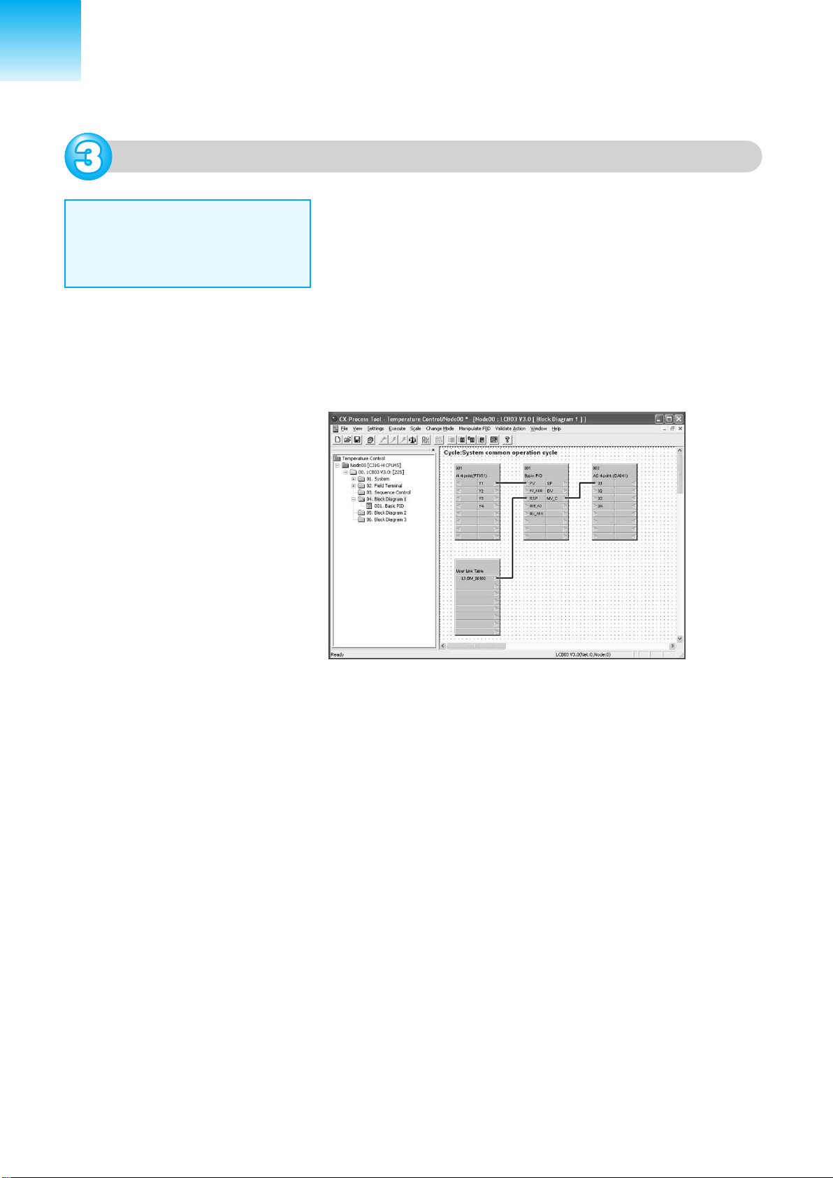
User Link Tables
User link tables are used to exchange data between user-set I/O
memory in the CPU Unit and function blocks in the Loop Controller.
Normally, Field Terminals are used for data exchange with I/O Units
and the HMI function is used for data exchange with I/O memory for
CPU Units. With these functions, however, the I/O memory
addresses for the CPU Unit are automatically allocated. User link
tables are useful for reading and writing data in the Loop Controller
to user-set memory area addresses in the CPU Unit. For example,
to read the remote set point (RSP) data from the DM Area in the
CPU Unit's I/O memory, allocate addresses in the DM Area to a
user link table and connect the table to the RSP of the PID Block. In
the following figure, D100 is allocated to a user link table, and the
table is connected to the RSP of the Basic PID Block.
Page 39
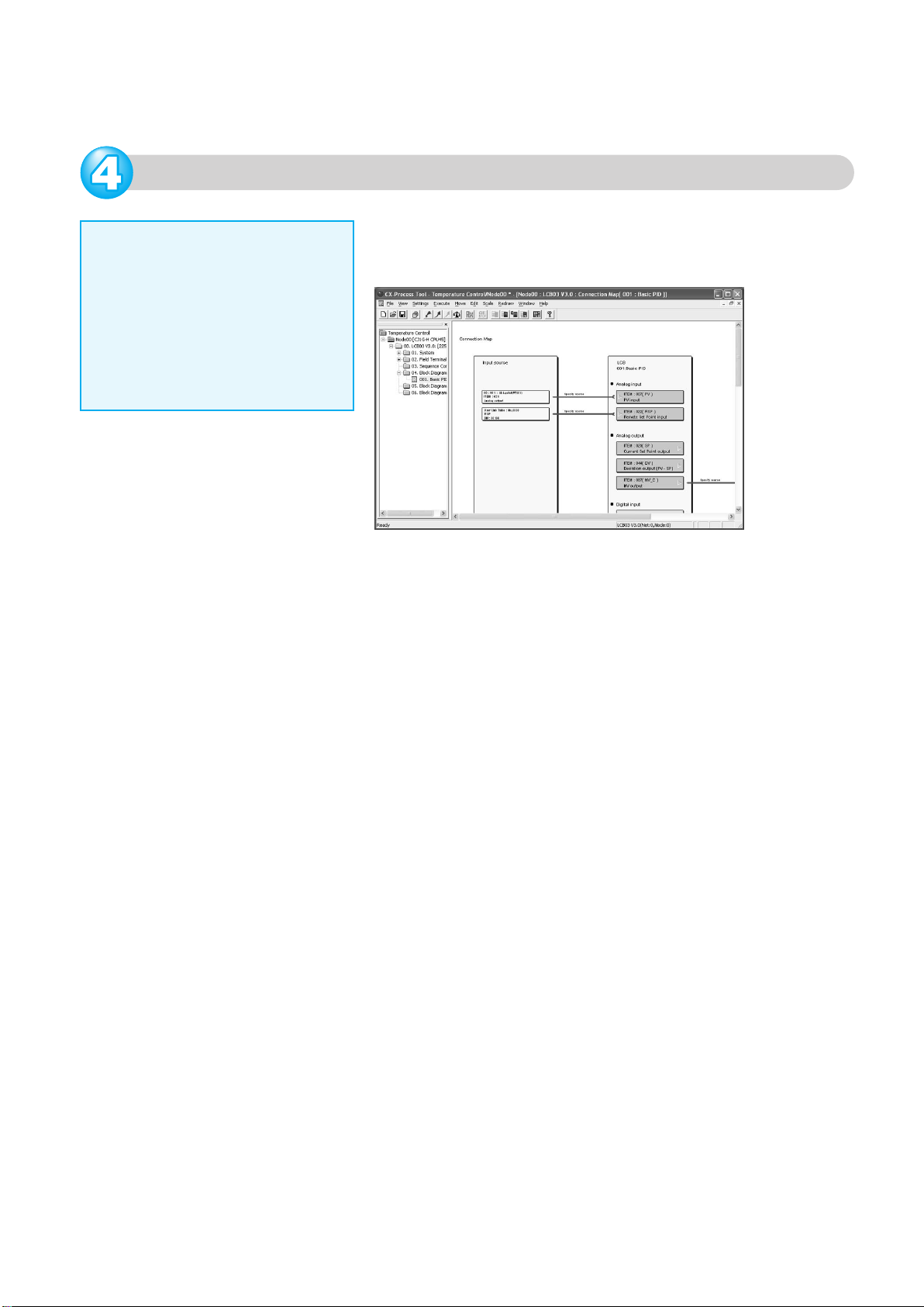
Connection Maps
Analog and contact information is
connected to function blocks. To
check the relationship of all I/O for
a function block, use a connection
map to display a relational diagram
for input source ITEMs and output
source ITEMs as a list.
To use connection maps, right-click the Basic PID Block on the
function block diagram. The connection map can be used by
selecting it from the menu.
Page 40
Warranty and Limitations of Liability
WARRANTY
OMRON's exclusive warranty is that the products are free from defects in materials and
workmanship for a period of one year (or other period if specified) from date of sale by OMRON.
OMRON MAKES NO WARRANTY OR REPRESENTATION, EXPRESS OR IMPLIED,
REGARDING NON-INFRINGEMENT, MERCHANTABILITY, OR FITNESS FOR PARTICULAR
PURPOSE OF THE PRODUCTS. ANY BUYER OR USER ACKNOWLEDGES THAT THE BUYER
OR USER ALONE HAS DETERMINED THAT THE PRODUCTS WILL SUITABLY MEET THE
REQUIREMENTS OF THEIR INTENDED USE. OMRON DISCLAIMS ALL OTHER WARRANTIES,
EXPRESS OR IMPLIED.
LIMITATIONS OF LIABILITY
OMRON SHALL NOT BE RESPONSIBLE FOR SPECIAL, INDIRECT, OR CONSEQUENTIAL
DAMAGES, LOSS OF PROFITS, OR COMMERCIAL LOSS IN ANY WAY CONNECTED WITH
THE PRODUCTS, WHETHER SUCH CLAIM IS BASED ON CONTRACT, WARRANTY,
NEGLIGENCE, OR STRICT LIABILITY.
In no event shall the responsibility of OMRON for any act exceed the individual price of the product
on which liability is asserted.
IN NO EVENT SHALL OMRON BE RESPONSIBLE FOR WARRANTY, REPAIR, OR OTHER
CLAIMS REGARDING THE PRODUCTS UNLESS OMRON'S ANALYSIS CONFIRMS THAT THE
PRODUCTS WERE PROPERLY HANDLED, STORED, INSTALLED, AND MAINTAINED AND
NOT SUBJECT TO CONTAMINATION, ABUSE, MISUSE, OR INAPPROPRIATE MODIFICATION
OR REPAIR.
Note: Do not use this document to operate the Unit.
This catalog mainly provides information that is necessary for selecting suitable models, and does
not contain precautions for correct use. Always read the precautions and other required information
provided in product operation manuals before using the product.
The application examples provided in this catalog are for reference only. Check functions and
safety of the equipment before use.
Never use the products for any application requiring special safety requirements, such as nuclear
energy control systems, railroad systems, aviation systems, medical equipment, amusement
machines, vehicles, safety equipment, or other application involving serious risk to life or property,
without ensuring that the system as a whole has been designed to address the risks, and that the
OMRON products are properly rated and installed for the intended use within the overall equipment
or system.
Printed on 100%
Recycled Paper
OMRON Corporation
Industrial Automation Company
Control Devices Division H.Q.
Shiokoji Horikawa, Shimogyo-ku,
Kyoto, 600-8530 Japan
Tel: (81)75-344-7109
Fax: (81)75-344-7149
Regional Headquarters
OMRON EUROPE B.V.
Wegalaan 67-69, NL-2132 JD Hoofddorp
The Netherlands
Tel: (31)2356-81-300/
Fax: (31)2356-81-388
OMRON ELECTRONICS LLC
1 East Commerce Drive, Schaumburg,
IL 60173 U.S.A.
Tel: (1)847-843-7900/ Fax: (1)847-843-8568
OMRON ASIA PACIFIC PTE. LTD.
83 Clemenceau Avenue,
#11-01, UE Square,
Singapore 239920
Tel: (65)6835-3011/Fax :(65)6835-2711
OMRON (CHINA) CO., LTD.
Room 2211, Bank of China Tower,
200 Yin Cheng Zhong Road,
PuDong New Area, Shanghai, 200120 China
Tel: (86)21-5037-2222/Fax: (86)21-5037-2200
Authorized Distributor:
Note: Specifications subject to change without notice. Cat. No. R143-E1-01
Printed in Japan
0606-1M
 Loading...