

Page 1

Cat. No. W433-E1-06
CX-Position Ver. 2.5
OPERATION MANUAL
Page 2

CXONE-AL@@C-V3/
CXONE-AL@@D-V3
CX-Position Ver. 2.5
Operation Manual
Revised June 2008
Page 3

iv
Page 4

Notice:
r
f
OMRON products are manufactured for use according to proper procedures by a qualified operator
and only for the purposes described in this manual.
The following conventions are used to indicate and classify precautions in this manual. Always heed
the information provided with them. Failure to heed precautions can result in injury to people or damage to property.
!DANGER Indicates an imminently hazardous situation which, if not avoided, will result in death or
serious injury. Additionally, there may be severe property damage.
!WARNING Indicates a potentially hazardous situation which, if not avoided, could result in death or
serious injury. Additional, there may be severe property damage.
!Caution Indicates a potentially hazardous situation which, if not avoided, may result in minor or
moderate injury, or property damage.
OMRON Product References
All OMRON products are capitalized in this manual. The word “Unit” is also capitalized when it refers to
an OMRON product, regardless of whether or not it appears in the proper name of the product.
The abbreviation “Ch,” which appears in some displays and on some OMRON products, often means
“word” and is abbreviated “Wd” in documentation in this sense.
The abbreviation “PLC” means Programmable Controller.
Visual Aids
The following headings appear in the left column of the manual to help you locate different types of
information.
OMRON, 2004
All rights reserved. No part of this publication may be reproduced, stored in a retrieval system, or transmitted, in any form, o
by any means, mechanical, electronic, photocopying, recording, or otherwise, without the prior written permission o
OMRON.
No patent liability is assumed with respect to the use of the information contained herein. Moreover, because OMRON is constantly striving to improve its high-quality products, the information contained in this manual is subject to change without
notice. Every precaution has been taken in the preparation of this manual. Nevertheless, OMRON assumes no responsibility
for errors or omissions. Neither is any liability assumed for damages resulting from the use of the information contained in
this publication.
Note Indicates information of particular interest for efficient and convenient opera-
tion of the product.
1,2,3... 1. Indicates lists of one sort or another, such as procedures, checklists, etc.
v
Page 5
Unit Versions of Position Control Units
Unit Versions A “unit version” has been introduced to manage Position Control Units accord-
ing to differences in functionality accompanying Unit upgrades.
Notation of Unit Versions
on Products
Example: CS-series Position Control Unit
Confirming Unit Versions
with Support Software
1,2,3... 1. In the IO Table Window, right-click and select Unit Manufacturing infor-
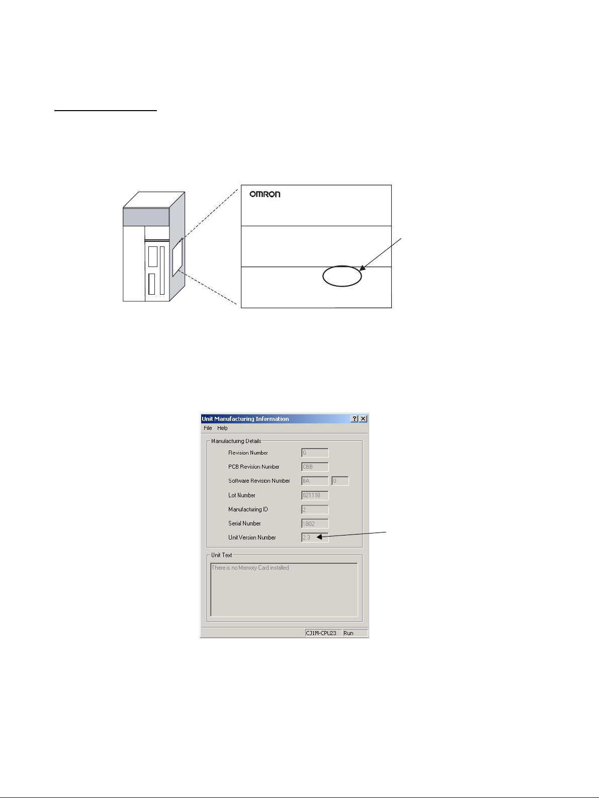
The unit version is given to the right of the lot number on the nameplate of the
applicable Position Control Units, as shown below.
Product nameplate
CS1W-NC113
NC UNIT
Unit version
Example for Unit version 2.3
Lot No. 031001 0000 Ver.2.3
OMRON Corporation MADE IN JAPAN
The unit version of the Position Control Units begins at version 2.0.
CX-Programmer version 4.0 or higher can be used to confirm the unit version
using the Unit Manufacturing information command.
mation - CPU Unit.
2. The following Unit Manufacturing information Dialog Box will be displayed
Using the Unit Version
Labels
vi
Unit version
Example for unit version 2.3
Use the above display to confirm the unit version of the Position Control Unit
connected online.
The following unit version labels are provided with the Position Control Unit.
These labels can be attached to the front of the Position Control Unit to differ-
entiate between Position Control Units of different unit versions.
Page 6
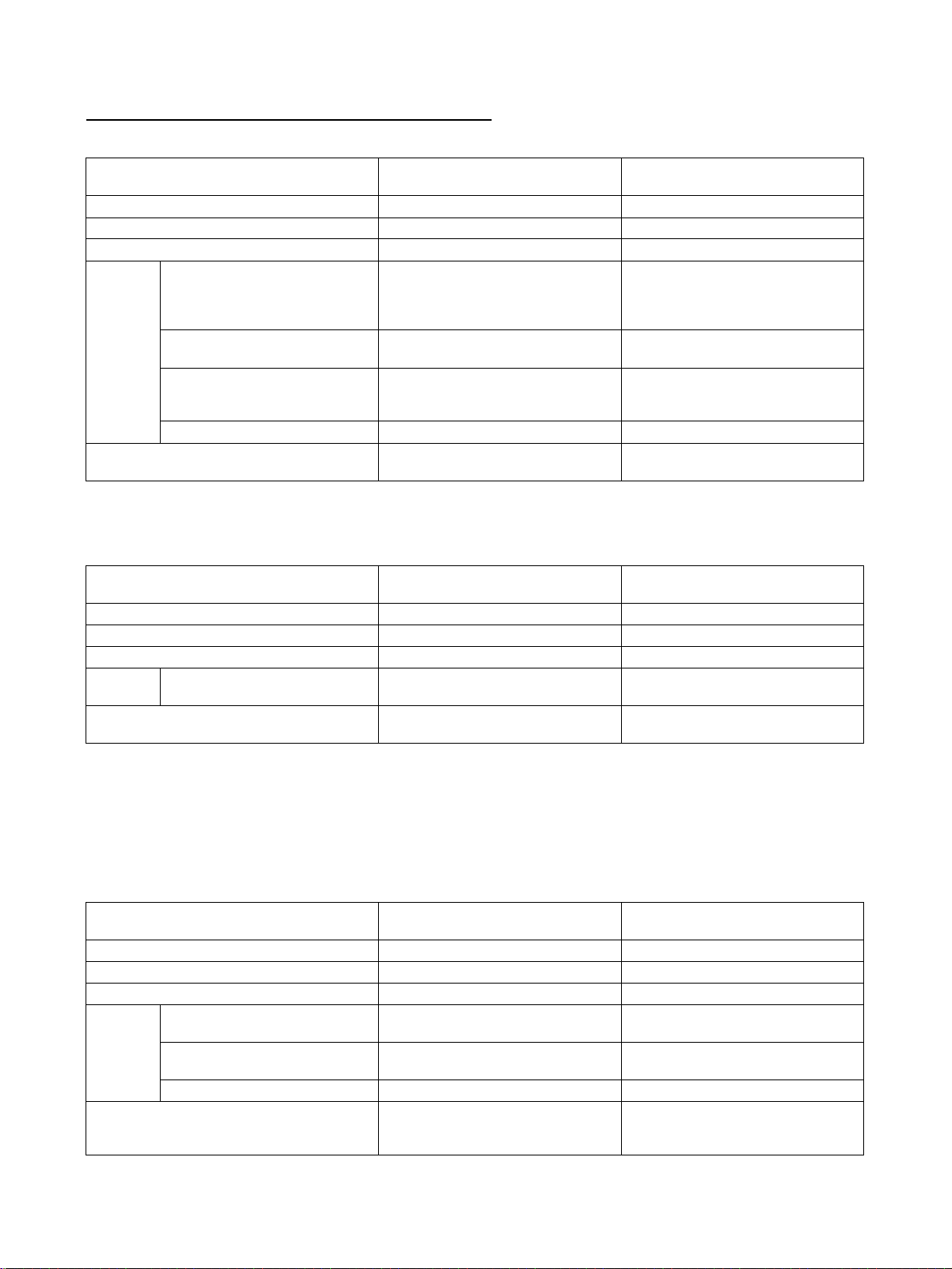
Function Support by Unit Version
Version Upgrade from Pre-version 2.0 to Position Control Units with Unit Version 2.0
Unit version Pre-version 2.0
Internal system software version 1.0 2.0
CS-series Position Control Units CS1W-NC113/133/213/233/413/433 CS1W-NC113/133/213/233/413/433
CJ-series Position Control Units CJ1W-NC113/133/213/233/413/433 CJ1W-NC113/133/213/233/413/433
Functions Changing rates of acceleration
when starting multiple axes during relative or absolute movements in direct operation
Changing rates of acceleration/
deceleration while jogging
Setting acceleration/deceleration times as the time required to
reach the target speed
Simple backup function --- OK
Support Software CX-Position Ver. 1.0 or higher CX-Position Ver. 1.0 (See note.)
Position Control Units
--- OK
--- OK
--- OK
Note With CX-Position version 1.0, new functions added to Position Control Units
with unit version 2.0 or later cannot be used.
Version Upgrade from Unit Version 2.0 to Unit Version 2.1
Unit version Position Control Units with
Internal system software version 2.0 2.1
CS-series Position Control Units CS1W-NC113/133/213/233/413/433 CS1W-NC113/133/213/233/413/433
CJ-series Position Control Units CJ1W-NC113/133/213/233/413/433 --Functions Unused axis setting
(See note 1.)
Support Software CX-Position Ver. 1.0 (See note 2.)
--- OK
CX-Position Ver. 2.0 or higher
unit version 2.0
Position Control Units with
unit version 2.0
CX-Position Ver. 2.0 or higher
Position Control Units with
unit version 2.1
CX-Position Ver. 1.0 (See note 2.)
CX-Position Ver. 2.0 (See note 3.)
Note 1. This setting is made in the DM Area of the CPU Unit.
2. New functions added to the Position Control Units with unit version 2.0 or
later cannot be used on the CX-Position version 1.0.
3. New functions added to the Position Control Units with unit version 2.1 or
later cannot be used on the CX-Position version 2.0.
Version Upgrade from Unit Version 2.1 to Unit Version 2.2
Unit version Position Control Units
with unit version 2.1
Internal system software version 2.1 2.2
CS-series Position Control Units CS1W-NC113/133/213/233/413/433 CS1W-NC113/133/213/233/413/433
CJ-series Position Control Units --- --Functions Switching pulse output direction
(CW or CCW)
Reversal mode 3 in origin search
operation
Position-preset origin search --- OK
Support Software CX-Position Ver. 1.0 (See note 1.)
--- OK
--- OK
CX-Position Ver 2.0 or higher
Position Control Units
with unit version 2.2
CX-Position Ver. 1.0 (See note 1.)
CX-Position Ver. 2.0 (See note 2.)
CX-Position Ver. 2.1 or higher
vii
Page 7
Note 1. New functions added to the Position Control Units with unit version 2.0 or
later cannot be used on the CX-Position version 1.0.
2. New functions added to the Position Control Units with unit version 2.2 or
later cannot be used on the CX-Position version 2.0.
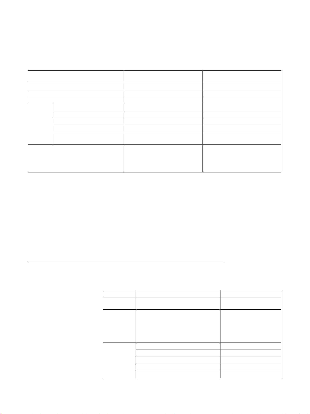
Version Upgrade from Version 2.2 to Version 2.3
Unit version Position Control Units
Internal system software version 2.2 2.3
CS-series Position Control Units CS1W-NC113/133/213/233/413/433 CS1W-NC113/133/213/233/413/433
CJ-series Position Control Units --- CJ1W-NC113/133/213/233/413/433
Functions Jogging with Support Software --- OK
Direct operation --- OK (See note 1.)
Origin searches --- OK (See note 1.)
Error counter reset output --- OK
Parameters or data check at
powering ON
Support Software CX-Position Ver. 1.0 (See note 2.)
--- OK
CX-Position Ver. 2.0 (See note 3.)
CX-Position Ver. 2.1 or higher
with unit version 2.2
Position Control Units
with unit version 2.3
CX-Position Ver. 1.0 (See note 2.)
CX-Position Ver. 2.0 (See note 3.)
CX-Position Ver. 2.1 (See note 4.)
CX-Position Ver. 2.2 (See note 5.)
CX-Position Ver. 2.3 or higher
Note 1. These functions can be used on the CX-Position version 2.3 or higher.
2. New functions added to the Position Control Units with unit version 2.0 or
later cannot be used on the CX-Position version 1.0.
3. New functions added to the Position Control Units with unit version 2.2 or
later cannot be used on the CX-Position version 2.0.
4. New functions added to the Position Control Units with unit version 2.3 or
later cannot be used on the CX-Position version 2.1.
5. Direct operation and origin searches, which were added to Position Control
Units with unit version 2.3 or later, cannot be used on the CX-Position version 2.2.
Position Control Unit Unit Versions and Internal Software Versions
In addition to the unit version, which is common to all CS/CJ-series Units, the
Position Control Units have an internal software version. The relationship
between the unit version and internal software version is shown in the following table.
Item Unit version Internal software version
Meaning This is the unit version used by all CS/
Confirmation
method
Relationship None given (Pre-version 2.0) 1.0
CJ-series Units.
Given to the right on the lot number on
the Position Control Unit nameplate.
Can also be confirmed using the Unit
Manufacturing information command
from the IO Table Window of the CXProgrammer.
Version 2.0 2.0
Version 2.1 2.1
Version 2.2 2.2
Version 2.3 2.3
This is the internal software
version of this Unit.
Can be confirmed by pressing the Ctrl+V Keys from the
NC Monitor Window of the
CX-Position.
viii
Page 8

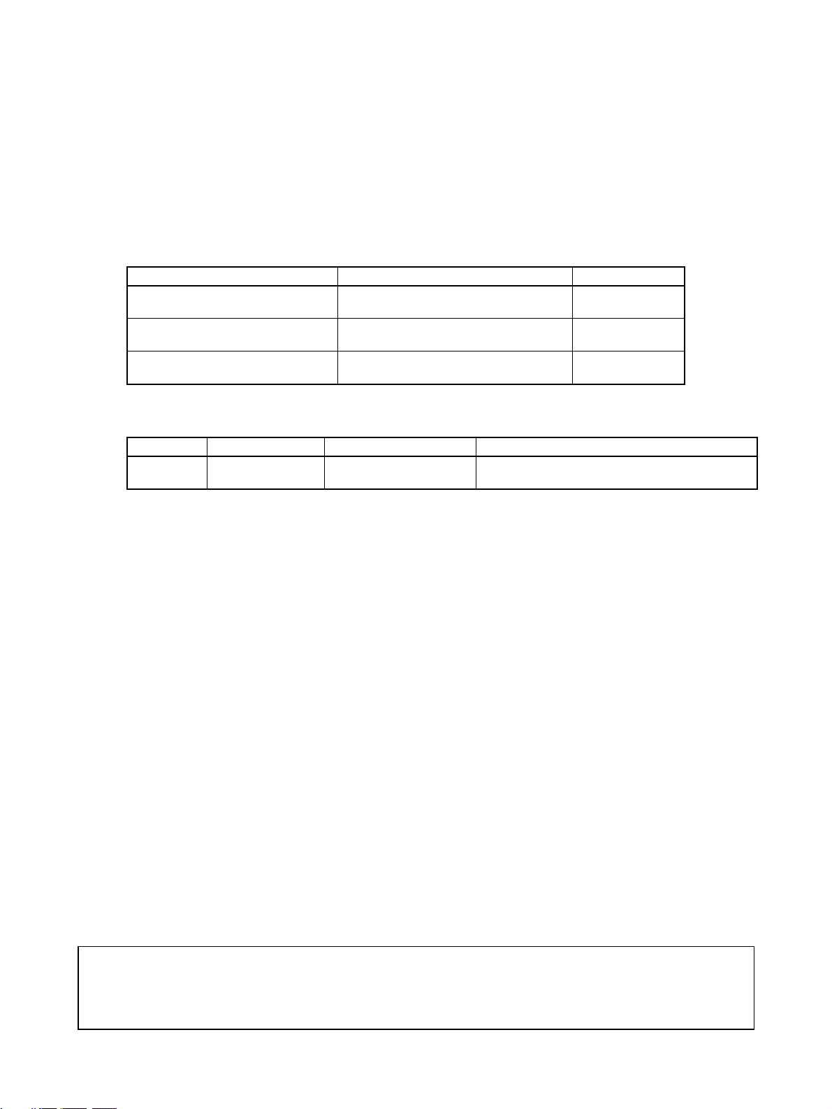
Version Upgrade Information
Improvements from Version 2.4 to Version 2.5
New Applicable CPU Units
Ver. 2.4 Ver. 2.5
Position Control Units in CS/CJ-series
PLCs (excluding CJ2 PLCs), CP-series
PLCs, NSJ-series Controllers, and FQM1
Motion Controllers were supported.
Improvements from Version 2.3 to Version 2.4
New Applicable OS
Ver. 2.3 Ver. 2.4
The CX-Position supports Windows 98,
Me, NT4.0, 2000, and XP.
Improvements from Version 2.2 to Version 2.3
Operating Functions Added for Position Control Units with Unit Version 2.3
Ver. 2.2 Ver. 2.3
The CX-Position can execute the following operations.
• JOG operations
Position Control Units in CS/CJ-series PLCs (including CJ2 PLCs), CP-series
PLCs, NSJ-series Controllers, and FQM1 Motion Controllers are supported.
The CX-Position supports Windows 98, Me, NT4.0, 2000, XP, and Vista.
The CX-Position can execute the following operations.
• JOG operations
• Origin searches
• Direct operation
Improvements from Version 2.1 to Version 2.2
Operating Functions Added for Position Control Units with Unit Version 2.3
Ver. 2.1 Ver. 2.2
The CX-Position could not execute JOG
operations.
The CX-Position could not turn ON/OFF
the Error Counter Output signal.
The CX-Position can execute JOG operations.
The CX-Position can turn ON/OFF the Error Counter Output signal.
Improvements from Version 2.0 to Version 2.1
Installing the CX-Position from the CX-One FA Integrated Tool Package
Ver. 2.0 Ver. 2.1
The CX-Position could be installed only
independently.
CX-Position Startup Method
Ver. 2.0 Ver. 2.1
The CX-Position could be started only
from the Windows Start Menu.
The CX-Position can be installed as one of the functions of the CX-One FA
Integrated Tool Package.
The CX-Position can also be started by right-clicking one of the following Position Control Units in the I/O Table Window opened from the CX-Programmer
that was installed from the CX-One and selecting Start Special Application
from the pop-up menu.
•CS1W-NC@@@
•CJ1W-NC@@@
Note When Start with Settings Inherited is selected, a new project will be
created, the device type setting will be automatically performed, and a
Position Control Unit will be automatically added.
ix
Page 9

Improvements from Version 1.0 to Version 2.0
The CX-Position has been upgraded from version 1.00 to version 2.00. See
the contents in the following table.
Item Existing version (Ver. 1.00) New version (Ver. 2.00)
Model WS02-NCTC1-E WS02-NCTC1-EV2
Communications
driver
OS Windows 95, 98, 2000, NT4.0 Windows 95, 98, 2000, XP,
Note Due to the change of the communications driver, another PLC Setup will be
required when opening a project file created with CX-Position version 1.00 on
CX-Position version 2.00. Additionally, data saved with version 2.00 format
cannot be read with version 1.00.
FinsGateway CX-Server
NT4.0
x
Page 10

TABLE OF CONTENTS
PRECAUTIONS . . . . . . . . . . . . . . . . . . . . . . . . . . . . . . . . . . . xvii
1 Intended Audience . . . . . . . . . . . . . . . . . . . . . . . . . . . . . . . . . . . . . . . . . . . . . . . . . . . . . . . . xviii
2 General Precautions . . . . . . . . . . . . . . . . . . . . . . . . . . . . . . . . . . . . . . . . . . . . . . . . . . . . . . . xviii
3 Safety Precautions. . . . . . . . . . . . . . . . . . . . . . . . . . . . . . . . . . . . . . . . . . . . . . . . . . . . . . . . . xviii
4 Application Precautions . . . . . . . . . . . . . . . . . . . . . . . . . . . . . . . . . . . . . . . . . . . . . . . . . . . .xix
5 Operating Environment Precautions . . . . . . . . . . . . . . . . . . . . . . . . . . . . . . . . . . . . . . . . . . . xx
SECTION 1
Overview . . . . . . . . . . . . . . . . . . . . . . . . . . . . . . . . . . . . . . . . . 1
1-1 Introduction. . . . . . . . . . . . . . . . . . . . . . . . . . . . . . . . . . . . . . . . . . . . . . . . . . . . . . . . . . . . . . 2
1-2 System Configuration . . . . . . . . . . . . . . . . . . . . . . . . . . . . . . . . . . . . . . . . . . . . . . . . . . . . . . 5
1-3 List of Functions . . . . . . . . . . . . . . . . . . . . . . . . . . . . . . . . . . . . . . . . . . . . . . . . . . . . . . . . . . 6
1-4 Comparison with SYSMAC-NCT . . . . . . . . . . . . . . . . . . . . . . . . . . . . . . . . . . . . . . . . . . . . 7
1-5 Basic Operating Procedure . . . . . . . . . . . . . . . . . . . . . . . . . . . . . . . . . . . . . . . . . . . . . . . . . .8
SECTION 2
Setup and Basic Procedures . . . . . . . . . . . . . . . . . . . . . . . . . 9
2-1 Installing and Uninstalling the Software. . . . . . . . . . . . . . . . . . . . . . . . . . . . . . . . . . . . . . . . 10
2-2 Connecting to a PLC. . . . . . . . . . . . . . . . . . . . . . . . . . . . . . . . . . . . . . . . . . . . . . . . . . . . . . . 10
2-3 Basic Operations . . . . . . . . . . . . . . . . . . . . . . . . . . . . . . . . . . . . . . . . . . . . . . . . . . . . . . . . . . 17
SECTION 3
Creating New Projects . . . . . . . . . . . . . . . . . . . . . . . . . . . . . . 37
3-1 Creating New Projects. . . . . . . . . . . . . . . . . . . . . . . . . . . . . . . . . . . . . . . . . . . . . . . . . . . . . . 38
3-2 Adding and Deleting PLCs . . . . . . . . . . . . . . . . . . . . . . . . . . . . . . . . . . . . . . . . . . . . . . . . . . 40
3-3 Adding and Deleting Position Control Units . . . . . . . . . . . . . . . . . . . . . . . . . . . . . . . . . . . . 44
3-4 Automatic Position Control Unit Search . . . . . . . . . . . . . . . . . . . . . . . . . . . . . . . . . . . . . . . 45
SECTION 4
Editing Settings . . . . . . . . . . . . . . . . . . . . . . . . . . . . . . . . . . . . 47
4-1 Overview. . . . . . . . . . . . . . . . . . . . . . . . . . . . . . . . . . . . . . . . . . . . . . . . . . . . . . . . . . . . . . . . 48
4-2 Setting Editing Windows. . . . . . . . . . . . . . . . . . . . . . . . . . . . . . . . . . . . . . . . . . . . . . . . . . . .51
4-3 Editing Parameter Settings . . . . . . . . . . . . . . . . . . . . . . . . . . . . . . . . . . . . . . . . . . . . . . . . . .60
4-4 Editing Sequence Settings. . . . . . . . . . . . . . . . . . . . . . . . . . . . . . . . . . . . . . . . . . . . . . . . . . .61
4-5 Editing Speed Settings . . . . . . . . . . . . . . . . . . . . . . . . . . . . . . . . . . . . . . . . . . . . . . . . . . . . . 63
4-6 Editing Acceleration/Deceleration Time Settings. . . . . . . . . . . . . . . . . . . . . . . . . . . . . . . . . 64
4-7 Editing Dwell Time Settings. . . . . . . . . . . . . . . . . . . . . . . . . . . . . . . . . . . . . . . . . . . . . . . . . 65
4-8 Editing Zone Settings . . . . . . . . . . . . . . . . . . . . . . . . . . . . . . . . . . . . . . . . . . . . . . . . . . . . . . 66
xi
Page 11

TABLE OF CONTENTS
SECTION 5
Saving and Reading Projects . . . . . . . . . . . . . . . . . . . . . . . . . 67
5-1 Saving Projects . . . . . . . . . . . . . . . . . . . . . . . . . . . . . . . . . . . . . . . . . . . . . . . . . . . . . . . . . . . 68
5-2 Reading Projects . . . . . . . . . . . . . . . . . . . . . . . . . . . . . . . . . . . . . . . . . . . . . . . . . . . . . . . . . . 68
SECTION 6
Transferring and Verifying Data . . . . . . . . . . . . . . . . . . . . . 71
6-1 Default Configurations for Connecting Online. . . . . . . . . . . . . . . . . . . . . . . . . . . . . . . . . . . 72
6-2 Setting and Changing Communications Specifications . . . . . . . . . . . . . . . . . . . . . . . . . . . . 72
6-3 Downloading Data . . . . . . . . . . . . . . . . . . . . . . . . . . . . . . . . . . . . . . . . . . . . . . . . . . . . . . . . 75
6-4 Uploading Data . . . . . . . . . . . . . . . . . . . . . . . . . . . . . . . . . . . . . . . . . . . . . . . . . . . . . . . . . . . 76
6-5 Verifying Data . . . . . . . . . . . . . . . . . . . . . . . . . . . . . . . . . . . . . . . . . . . . . . . . . . . . . . . . . . . . 78
6-6 Writing Data to Flash Memory . . . . . . . . . . . . . . . . . . . . . . . . . . . . . . . . . . . . . . . . . . . . . . . 80
SECTION 7
Monitoring Position Control Units . . . . . . . . . . . . . . . . . . . . 81
7-1 Monitoring Position Control Units . . . . . . . . . . . . . . . . . . . . . . . . . . . . . . . . . . . . . . . . . . . . 82
7-2 Multiple Unit Monitoring . . . . . . . . . . . . . . . . . . . . . . . . . . . . . . . . . . . . . . . . . . . . . . . . . . .83
7-3 Operating Memory Area Monitoring . . . . . . . . . . . . . . . . . . . . . . . . . . . . . . . . . . . . . . . . . . 84
7-4 Operating Data Area Monitoring . . . . . . . . . . . . . . . . . . . . . . . . . . . . . . . . . . . . . . . . . . . . . 84
SECTION 8
Test Run Operation . . . . . . . . . . . . . . . . . . . . . . . . . . . . . . . . 87
8-1 Test Run Settings. . . . . . . . . . . . . . . . . . . . . . . . . . . . . . . . . . . . . . . . . . . . . . . . . . . . . . . . . . 88
8-2 Test Run . . . . . . . . . . . . . . . . . . . . . . . . . . . . . . . . . . . . . . . . . . . . . . . . . . . . . . . . . . . . . . . . 88
SECTION 9
Error Counter Reset Output . . . . . . . . . . . . . . . . . . . . . . . . . 93
9-1 Error Counter Reset Output . . . . . . . . . . . . . . . . . . . . . . . . . . . . . . . . . . . . . . . . . . . . . . . . . 94
SECTION 10
Printing Data. . . . . . . . . . . . . . . . . . . . . . . . . . . . . . . . . . . . . . 97
10-1 Printing Data . . . . . . . . . . . . . . . . . . . . . . . . . . . . . . . . . . . . . . . . . . . . . . . . . . . . . . . . . . . . . 98
SECTION 11
Error Logs and Troubleshooting . . . . . . . . . . . . . . . . . . . . . 101
11-1 Position Control Unit Error Logs . . . . . . . . . . . . . . . . . . . . . . . . . . . . . . . . . . . . . . . . . . . . . 102
11-2 Troubleshooting . . . . . . . . . . . . . . . . . . . . . . . . . . . . . . . . . . . . . . . . . . . . . . . . . . . . . . . . . . 117
Revision History . . . . . . . . . . . . . . . . . . . . . . . . . . . . . . . . . . . 119
xii
Page 12
About this Manual:
This manual describes the specifications and operation of the CX-Position software and includes the
sections described below. The CX-Position runs on Windows 2000, XP, or Vista operating systems and
is used to create data for and monitor the operation of the CS1W-NC@@@ and CJ1W-NC@@@ Position Control Units (also referred to as NC Units).
Please read this manual carefully and be sure you understand the information provided before
attempting to install and operate CX-Position. Please read the following manuals carefully and be sure
you understand the information provided before using a Position Control Unit.
Model Manual name Cat. No.
CXONE-AL@@C-V3
CXONE-AL@@D-V3
CS1W-NC113/213/413/133/233/433 CS1W-NC113/213/413/133/233/433
CJ1W-NC113/213/413/133/233/433 CJ1W-NC113/213/413/133/233/433
For details on procedures for installing the CX-Position from the CX-One FA Integrated Tool Package,
refer to the CX-One Ver. 3.0 Setup Manual provided with CX-One.
Cat. No. Model Name Contents
W463 CXONE-AL@@C-
V3/AL@@D-V3
CX-Position Operation Manual W433
Position Control Units Operation Manual
Position Control Units Operation Manual
CX-One Ver. 3.0 Setup
Manual
Installation and overview of CX-One FA Integrated Tool Package.
(this manual)
W376
W397
Precautions provides general precautions for using CX-Position and related devices.
Section 1 provides an overview of CX-Position, its functions, and the system configuration in which it
is used.
Section 2 provides information about CX-Position installation, connecting to the PLC, and basic operating procedures.
Section 3 describes the procedures for creating new projects, as well as those for adding and deleting
Programmable Controllers (PLCs) and Position Control Units (NCs).
Section 4 describes the procedures used to edit settings.
Section 5 provides information about saving and reading files.
Section 6 provides information on data transfer and verification operations between the CX-Position
and Position Control Units, and about operations for writing data transferred to Position Control Units
into the Position Control Unit flash memory.
Section 7 provides information about monitoring Position Control Units. The Position Control Unit’s
current positions, error codes, and status are displayed on the NC Monitor. Monitor Units are also
available, displaying sequence numbers and current positions for up to four Units simultaneously.
Operating memory area monitoring, operating data area monitoring, and Position Control Unit error
logs can also be displayed. For details on NC error log display, refer to 11-1 Position Control Unit Error
Logs.
Section 8 section describes the test run operations for each axis.
Section 9 describes the error counter reset output.
Section 10 provides information about printing data.
Section 11 provides information about Position Control Unit error log displays and troubleshooting.
!WARNING Failure to read and understand the information provided in this manual may result in per-
sonal injury or death, damage to the product, or product failure. Please read each section
in its entirety and be sure you understand the information provided in the section and
related sections before attempting any of the procedures or operations given.
xiii
Page 13

xiv
Page 14

Read and Understand this Manual
Please read and understand this manual before using the product. Please consult your OMRON
representative if you have any questions or comments.
Warranty and Limitations of Liability
WARRANTY
(1) The warranty period for the Software is one year from either the date of purchase or the date on which
the Software is delivered to the specified location.
(2) If the User discovers a defect in the Software (i.e., substantial non-conformity with the manual), and
returns it to OMRON within the above warranty period, OMRON will replace the Software without charge
by offering media or downloading services from the Internet. And if the User discovers a defect in the
media which is attributable to OMRON and returns the Software to OMRON within the above warranty
period, OMRON will replace the defective media without charge. If OMRON is unable to replace the
defective media or correct the Software, the liability of OMRON and the User's remedy shall be limited to
a refund of the license fee paid to OMRON for the Software.
LIMITATIONS OF LIABILITY
(1) THE ABOVE WARRANTY SHALL CONSTITUTE THE USER'S SOLE AND EXCLUSIVE REMEDIES
AGAINST OMRON AND THERE ARE NO OTHER WARRANTIES, EXPRESSED OR IMPLIED,
INCLUDING BUT NOT LIMITED TO, WARRANTY OF MERCHANTABILITY OR FITNESS FOR A
PARTICULAR PURPOSE. IN NO EVENT WILL OMRON BE LIABLE FOR ANY LOST PROFITS OR
OTHER INDIRECT, INCIDENTAL, SPECIAL, OR CONSEQUENTIAL DAMAGES ARISING OUT OF
USE OF THE SOFTWARE.
(2) OMRON SHALL ASSUME NO LIABILITY FOR DEFECTS IN THE SOFTWARE BASED ON
MODIFICATION OR ALTERATION OF THE SOFTWARE BY THE USER OR ANY THIRD PARTY.
(3) OMRON SHALL ASSUME NO LIABILITY FOR SOFTWARE DEVELOPED BY THE USER OR ANY
THIRD PARTY BASED ON THE SOFTWARE OR ANY CONSEQUENCE THEREOF.
Application Considerations
SUITABILITY FOR USE
THE USER SHALL NOT USE THE SOFTWARE FOR A PURPOSE THAT IS NOT DESCRIBED IN THE
ATTACHED USER MANUAL.
xv
Page 15

Disclaimers
CHANGE IN SPECIFICATIONS
The software specifications and accessories may be changed at any time based on improvements or for
other reasons.
EXTENT OF SERVICE
The license fee of the Software does not include service costs, such as dispatching technical staff.
ERRORS AND OMISSIONS
The information in this manual has been carefully checked and is believed to be accurate; however, no
responsibility is assumed for clerical, typographical, or proofreading errors, or omissions.
xvi
Page 16

PRECAUTIONS
This section provides general precautions for using CX-Position and related devices.
The information contained in this section is important for the safe and reliable application of CX-Position. You must
read this section and understand the information contained before attempting to set up or operate the CX-Position.
1 Intended Audience . . . . . . . . . . . . . . . . . . . . . . . . . . . . . . . . . . . . . . . . . . . . . xviii
2 General Precautions . . . . . . . . . . . . . . . . . . . . . . . . . . . . . . . . . . . . . . . . . . . . xviii
3 Safety Precautions. . . . . . . . . . . . . . . . . . . . . . . . . . . . . . . . . . . . . . . . . . . . . . xviii
4 Application Precautions . . . . . . . . . . . . . . . . . . . . . . . . . . . . . . . . . . . . . . . . . xix
5 Operating Environment Precautions . . . . . . . . . . . . . . . . . . . . . . . . . . . . . . . . xx
xvii
Page 17

Intended Audience 1
1 Intended Audience
This manual is intended for the following personnel, who must also have
knowledge of electrical systems (an electrical engineer or the equivalent).
• Personnel in charge of installing FA systems.
• Personnel in charge of designing FA systems.
• Personnel in charge of managing FA systems and facilities.
2 General Precautions
The user must operate the product according to the performance specifications described in the operation manuals.
Before using the product under conditions which are not described in the
manual or applying the product to nuclear control systems, railroad systems,
aviation systems, vehicles, combustion systems, medical equipment, amusement machines, safety equipment, and other systems, machines, and equipment that may have a serious influence on lives and property if used
improperly, consult your OMRON representative.
Make sure that the ratings and performance characteristics of the product are
sufficient for the systems, machines, and equipment, and be sure to provide
the systems, machines, and equipment with double safety mechanisms.
This manual provides information for using CX-Position. Be sure to read this
manual before attempting to use CX-Position and keep this manual close at
hand for reference during operation.
!WARNING It is extremely important that CX-Position and related devices be used for the
specified purpose and under the specified conditions, especially in applications that can directly or indirectly affect human life. You must consult with
your OMRON representative before applying CX-Position and related devices
to the above mentioned applications.
3 Safety Precautions
!WARNING Never attempt to disassemble any Units while power is being supplied. Doing
so may result in serious electric shock.
!WARNING Never touch any of the terminals while power is being supplied. Doing so may
result in serious electric shock.
!Caution Save parameters and other data to flash memory after transferring them to
the Position Control Unit. If parameters and other data are not saved to flash
memory, data will return to their previous values the next time power is turned
ON, possibly resulting in Unit malfunction.
!Caution Confirm safety at the destination node before transferring parameters or other
data to the node. Transferring parameters or other data without confirming
safety may result in injury.
xviii
!Caution Check that the axis number is correct before operating an axis from the CX-
Position.
Page 18

Application Precautions 4
!Caution Do not save data to flash memory during memory operation or while the
motor is running. Doing so may result in unexpected operation.
4 Application Precautions
!Caution Observe the following precautions when using CX-Position.
• Confirm the unit number before transferring parameters and other data to
a Position Control Unit.
• Confirm that set parameters and data operate properly before using in
actual operation.
• When the settings of the following parameters have been changed, they
must be transferred to the Position Control Unit and written to flash memory, and then the Position Control Unit must be turned OFF and back ON,
or restarted as a Special I/O Unit, to enable using the new settings.
• Output pulse selection
• Output pulse direction
• Limit input signal type
• Origin proximity input signal type
• Origin input signal type
• Emergency stop input function
• No-origin specification
• Operating mode selection
• Origin search operation
• Origin detection method
• Origin search direction
• Position-preset origin search
• Do not turn OFF the power to a Position Control Unit while writing to flash
memory. Doing so may damage flash memory.
• Confirm that no adverse effect will occur in the system before attempting
any of the following. Not doing so may result in unexpected operation.
• Changing the operating mode of the PLC (including the operating
mode at startup).
• Changing the present value of any word or any set value in memory.
• Force-setting/force-resetting any bit in memory.
• Do not turn OFF the power to the computer while installing or uninstalling
CX-Position. Doing so may corrupt computer data.
xix
Page 19

Operating Environment Precautions 5
5 Operating Environment Precautions
!Caution Perform installation properly, according to the procedures described in this
manual.
!Caution Do not install in the following locations:
• Locations subject to direct sunlight.
• Locations subject to temperatures or humidity outside the range specified
in the specifications.
• Locations subject to condensation as the result of severe changes in temperature.
• Locations subject to corrosive or flammable gases.
• Locations subject to dust (especially iron dust) or salts.
• Locations subject to exposure to water, oil, or chemicals.
• Locations subject to shock or vibration.
!Caution Take appropriate and sufficient countermeasures when installing in the follow-
ing locations:
• Locations subject to static electricity or other forms of noise.
• Locations subject to strong electromagnetic fields.
• Locations subject to possible exposure to radioactivity.
• Locations close to power supplies.
xx
Page 20

SECTION 1
Overview
This section provides an overview of CX-Position, its functions, and the system configuration in which it is used.
1-1 Introduction. . . . . . . . . . . . . . . . . . . . . . . . . . . . . . . . . . . . . . . . . . . . . . . . . . . 2
1-1-1 What Is CX-Position?. . . . . . . . . . . . . . . . . . . . . . . . . . . . . . . . . . . . 2
1-1-2 Applicable Position Control Units . . . . . . . . . . . . . . . . . . . . . . . . . . 2
1-1-3 Features. . . . . . . . . . . . . . . . . . . . . . . . . . . . . . . . . . . . . . . . . . . . . . . 3
1-1-4 Applicable Computers . . . . . . . . . . . . . . . . . . . . . . . . . . . . . . . . . . . 4
1-1-5 CX-Position Data . . . . . . . . . . . . . . . . . . . . . . . . . . . . . . . . . . . . . . . 4
1-1-6 Software Structure . . . . . . . . . . . . . . . . . . . . . . . . . . . . . . . . . . . . . . 4
1-2 System Configuration . . . . . . . . . . . . . . . . . . . . . . . . . . . . . . . . . . . . . . . . . . . 5
1-3 List of Functions . . . . . . . . . . . . . . . . . . . . . . . . . . . . . . . . . . . . . . . . . . . . . . . 6
1-4 Comparison with SYSMAC-NCT . . . . . . . . . . . . . . . . . . . . . . . . . . . . . . . . . 7
1-5 Basic Operating Procedure . . . . . . . . . . . . . . . . . . . . . . . . . . . . . . . . . . . . . . . 8
1
Page 21

Introduction Section 1-1
1-1 Introduction
1-1-1 What Is CX-Position?
The CX-Position is a software package that enables the setting, transfer, storage, and printing of data used with Position Control Units (also referred to as
NC Units), as well as monitoring of Position Control Unit operating status.
The CX-Position runs on a Windows 2000, XP, or Vista operating system.
Computer with
Windows
operating system
Data (e.g., parameter
Position
Control Unit
data, position data) used
with the Position Control
Unit is set and transferred.
The Position Control Unit’s
operating status (e.g.,
present position, I/O status,
and error display) is
monitored.
1-1-2 Applicable Position Control Units
CX-Position can be used with the following Position Control Units.
Position Control Unit model number PLC series
CS1W-NC113/133/213/233/413/433 CS Series
CJ1W-NC113/133/213/233/413/433 CJ-series PLCs, CP-series PLCs,
Note The CX-Position supports only FQM1 Flexible Motion Controllers with unit
version 3.2 or later.
For details on the system configuration, refer to 1-2 System Configuration.
NSJ-series NSJ Controllers, and
FQM1 Flexible Motion Controllers
(See note.)
2
Page 22
Introduction Section 1-1
1-1-3 Features
Data Management and
Editing in Project Units
Individual Copying and
Moving of Position
Control Unit Data
Communications with
Position Control Units via
Networks
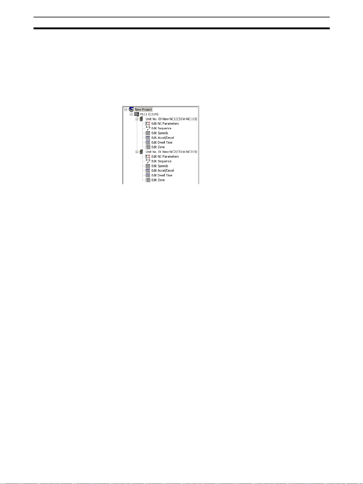
The CX-Position enables data for several Position Control Units (96 Position
Control Units max. per PLC) on several PLCs (1,000 max.) to be handled as 1
project. Data is displayed in tree format with parameter data, sequence data,
speed data, acceleration/deceleration data, dwell times, and zone data displayed under the corresponding Position Control Unit, Position Control Units
displayed under the corresponding PLC, and PLCs displayed under the corresponding project.
Position Control Unit data, such as parameters, sequences, and speeds, can
be moved or copied (overwritten) between PLCs in the project tree. This feature enables editing and re-use of the same or similar data with other PLCs or
Position Control Units.
The CX-Position communicates with Position Control Units using CX-Server.
Depending on the type of CX-Server driver used, online operations (e.g.,
monitoring and transfer/verification of parameter and sequence data) are possible via Host Link (SYSMAC WAY) or Toolbus.
Automatic Project
Generation
Importing SYSMAC-NCT
Data
The CX-One FA integrated Tool Package, which includes the CX-Position, will provide the total solution
for a wide range of system development.
The CX-Position can read information about the Position Control Units
mounted on a PLC connected online, and automatically create a project
based on this information. (CX-Position can also upload actual data from Position Control Units and use it in the project.) This feature eliminates the necessity of creating a new project offline before going online.
Data created for the C200HW-NC@@@ using the SYSMAC-NCT (with .ncm
file extension) can be imported and used as data for the CS1W-NC@@@ or
CJ1W-NC@@@.
The CX-Position can now be started from the I/O Table Window of the CXProgrammer with the communications settings inherited from the CX-Programmer.
Starting the CX-Position with the communications settings inherited will automatically register the communications settings between the PLC and personal
computer, Position Control Unit models, unit numbers, and other settings in
the CX-Position project file.
Data such as parameters, however, will be initialized.
The CX-Position project files are saved in the same data folder as the CX-Pro-
grammer project files, which makes data management easier.
3
Page 23

Introduction Section 1-1
1-1-4 Applicable Computers
Refer to the CX-One Ver. 3.0 Setup Manual (W463) for the computer system
requirements for the CX-Position.
1-1-5 CX-Position Data
The CX-Position is used to make project files with the configuration shown
below. The file extension for project files is .nci.
Project file (“.nci”)
1,000 PLCs max.
One “PLC” contains the data for 1 PLC
(CPU Unit). One project file can contain
up to 1,000 PLCs. One “NC” contains all
the data for 1 Position Control Unit.
PLC
PLC
NC
NC
NC
NC
NC
Parameter data
Sequence data
Speed data
Acceleration/deceleration data
Dwell times
Zone data
96 Units max. (See note.)
Note The number of Position Control
Units is restricted by the number
of allocated unit numbers and
the current consumption.
1-1-6 Software Structure
The CX-Position exchanges data (online communications) with Position Control Units via CX-Server. In order to execute functions online, CX-Server must
be installed on the same computer as CX-Position.
4
Page 24
System Configuration Section 1-2
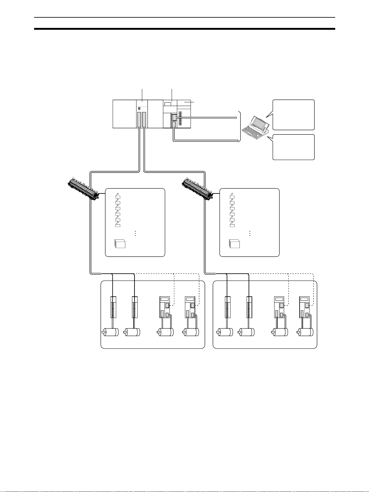
1-2 System Configuration
The system configuration for the Position Control Units is given below with the
CS1W-NC413/433 used as a representative example. The CS1W-NC213/233
and CS1W-NC113/133 are used for control of 2 axes and 1 axis respectively.
Position Control Unit
(CS1W-NC413/433)
CPU Unit
(CS Series)
Dedicated
terminal block
0
2
1
2
2
0
2
1
3
2
4
2
2
5
3
2
4
5
Power Supply Unit
Host Link
Host Link
Dedicated
6
2
7
2
6
8
2
7
9
2
0
8
3
9
1
3
2
10
3
11
3
3
12
4
3
3
1
5
3
4
1
5
1
6
3
7
3
6
8
1
3
7
1
9
3
8
1
9
1
External inputs
CCW limit input
CW limit input
Origin input
Origin proximity input
Emergency stop input
Interrupt input
Interface power
supply (24 V)
terminal block
0
2
1
2
0
22
1
3
2
4
2
2
5
3
2
6
4
2
7
5
2
6
8
2
7
9
2
0
8
3
9
1
3
2
10
3
11
3
3
12
4
3
3
1
5
3
4
1
6
3
5
7
1
3
6
1
7
1
8
3
9
3
8
1
9
1
External inputs
CCW limit input
CW limit input
Origin input
Origin proximity input
Emergency stop input
Interrupt input
Interface power
supply (24 V)
CX-Programmer
Creation and
transfer of ladder
programs,
monitoring, file
management, etc.
CX-Position
Creation and
transfer of data, Unit
monitoring, file
management, etc.
Stepping
motor
drivers
Stepping motors
or
Servomotor
drivers
Servomotors
Stepping
motor
drivers
Stepping motors
Servomotor
drivers
or
Servomotors
Note 1. Special cables are available to connect OMRON U-series Drivers, W-se-
ries Drivers, G-series Drivers, SMARTSTEP 2-series Drivers, SMARTSTEP A-series Drivers, or SMARTSTEP Junior Drivers. Cables made by
the user can also be used.
2. Special cables are available for connections to special terminal blocks. Cables made by the user can also be used.
5
Page 25

List of Functions Section 1-3
1-3 List of Functions
Group Function Details Page
Editing projects Create project Used to create project files (“.nci”). page 38
Create PLC Used to specify a PLC model and add PLC data to a project. page 40
Create NC Unit Used to specify a Position Control Unit model and add Position
Control Unit data to a PLC in a project.
Edit PLC/NC Unit Used to perform editing for a project, such as making property
settings for or deleting PLCs or Position Control Units, cutting,
copying, or pasting Position Control Units, pasting Position Control Unit data, and drag-and-drop.
Editing NC Unit
data
Saving and
loading project
files
Importing NCT
data files
Online Download/upload/verify Used to download, upload, or verify data. page 75,
Edit Used to edit the Posi-
Save Used to save all the data in a project as a project file (“.nci”). page 68
Load Used to read a project file (“.nci”) to a project. page 68
Import Used to import data files created with SYSMAC-NCT to CX-
Flash memory write Used to write data to flash memory. page 80
Monitor Used to display the sequence number, present position, I/O sta-
Monitor Units Used to display the sequence numbers, present positions, I/O
Automatic project setting Used to read information about the Position Control Units
Operating memory area
monitor
Operating data area
monitor
Test run Used to execute JOG operations, origin searches, and direct
Error counter reset output
NC Unit error log monitor
tion Control Unit data
shown on the right.
Position projects.
tus, and error code for a Position Control Unit.
statuses, and error codes for 4 Position Control Units.
mounted on a specified PLC connected online, and creates a
project tree based on this. If the data upload checkbox is
selected, the data for all Position Control Units on the specified
PLC is read and included in the project.
Used to monitor the CPU Unit’s operating memory area. page 84
Used to monitor the CPU Unit’s operating data area. page 84
operation.
Used to turn ON/OFF the error counter reset output signal. page 94
Used to monitor items (20 max. per Position Control Unit) in
Position Control Unit error logs.
Parameter data page 60
Sequence data page 61
Speed data page 63
Acceleration/deceleration time data page 64
Dwell time data page 65
Zone data page 66
page 44
page 44
page 69
page 76,
page 78
page 82
page 83
page 45,
page 77
page 88
page 102
6
Page 26

Comparison with SYSMAC-NCT Section 1-4
1-4 Comparison with SYSMAC-NCT
Item CX-Position SYSMAC-NCT
Position Control Unit CS1W-NC@@@
CJ1W-NC@@@
Created files Project files (“.nci”) created with the data from more than
1 Position Control Unit mounted on more than 1 PLC
(1,000 max.)
Managing and editing using projects
Method for connecting to PLC
Networks for connection to PLC
Decimal/binary display selection
Changing display
font size
Position Control Unit
error log display
Supported
Within a project, data can be moved or copied (see note)
in units of Position Control Units using “drag-and-drop”
and “copy-and-paste” operations. (Data can be moved or
copied within the same PLC or between PLCs.)
Note The data at the Position Control Unit to which
data is copied is overwritten. Icons are not copied
along with the data.
• Connected to the RS-232C port on the CPU Unit or a
Serial Communications Board/Unit using an RS-232C
cable.
• Connected to the peripheral port on the CPU Unit
using a peripheral cable.
Select from the following for the CX-Server network type
to connect to PLCs on networks:
• Toolbus
• SYSMAC WAY (Host Link)
Supported. Not supported (decimal only).
Supported. Not supported.
Supported. Not supported.
C200HW-NC@@@
C500-NC@@@
Data files (C200HW-NC: “.ncm”; C500NC: “.ncl”) created with the data from 1
Position Control Unit
Not supported
All data is handled together. (Moving
and copying in units of Position Control
Units is not possible.)
Connected to the RS-232C port on the
CPU Unit using an RS-232C cable.
Host Link (RS-232C) only
7
Page 27
Basic Operating Procedure Section 1-5
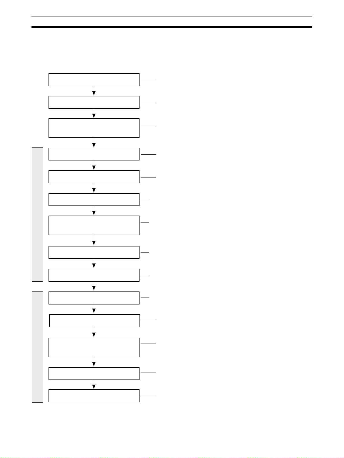
1-5 Basic Operating Procedure
A basic outline of the procedures required to install the CX-Position and CXServer, create data, transfer it to the Position Control Units, and use in actual
operation is given below.
Install CX-Position.
Install CX-Server.
Connect to the CPU Unit’s
built-in RS-232C port.
Start CX-Position.
Create a new project.
Add PLCs to the project
Add Position Control Units to the PLCs in
the project.
Offline operations
Refer to 2-1 Installing and Uninstalling the Software.
Refer to 2-1 Installing and Uninstalling the Software.
Refer to 2-2 Connecting to a PLC.
Refer to 2-3 Basic Operations.
Refer to 3-1 Creating New Projects.
Refer to 3-2 Adding and Deleting PLCs.
Refer to 3-3 Adding and Deleting Position Control Units.
Create/edit Position Control Unit
Save the project.
Initialize the Position Control Units
and CPU Unit.
Download data to the Position Control
Units.
Write data to the flash memory in Position
Control Units.
Online operations
Perform positioning with the Position
Control Units.
Monitor the Position Control Units.
Refer to SECTION 4 Editing Settings.
Refer to SECTION 5 Saving and Reading Projects.
Refer to 6-3 Downloading Data.
Refer to 6-3 Downloading Data.
Refer to 6-6 Writing Data to Flash Memory.
Refer to the Operation Manual for the Position Control Unit.
Refer to SECTION 7 Monitoring Position Control Units.
8
Page 28

SECTION 2
Setup and Basic Procedures
This section provides information about CX-Position installation, connecting to the PLC, and basic operating procedures.
2-1 Installing and Uninstalling the Software. . . . . . . . . . . . . . . . . . . . . . . . . . . . . 10
2-1-1 Software That Must Be Installed . . . . . . . . . . . . . . . . . . . . . . . . . . . 10
2-2 Connecting to a PLC. . . . . . . . . . . . . . . . . . . . . . . . . . . . . . . . . . . . . . . . . . . . 10
2-2-1 Connecting to CS/CJ-series PLCs . . . . . . . . . . . . . . . . . . . . . . . . . . 10
2-2-2 Connecting to CP-series PLCs . . . . . . . . . . . . . . . . . . . . . . . . . . . . . 15
2-2-3 Connecting to CJ2 PLCs. . . . . . . . . . . . . . . . . . . . . . . . . . . . . . . . . . 16
2-3 Basic Operations . . . . . . . . . . . . . . . . . . . . . . . . . . . . . . . . . . . . . . . . . . . . . . . 17
2-3-1 Starting . . . . . . . . . . . . . . . . . . . . . . . . . . . . . . . . . . . . . . . . . . . . . . . 17
2-3-2 Quitting. . . . . . . . . . . . . . . . . . . . . . . . . . . . . . . . . . . . . . . . . . . . . . . 17
2-3-3 Basic Window . . . . . . . . . . . . . . . . . . . . . . . . . . . . . . . . . . . . . . . . . . 18
2-3-4 Displaying Menus. . . . . . . . . . . . . . . . . . . . . . . . . . . . . . . . . . . . . . . 20
2-3-5 Moving and Copying Position Control Unit Data . . . . . . . . . . . . . . 20
2-3-6 Main Menus . . . . . . . . . . . . . . . . . . . . . . . . . . . . . . . . . . . . . . . . . . . 23
2-3-7 Main Menu Items . . . . . . . . . . . . . . . . . . . . . . . . . . . . . . . . . . . . . . . 24
2-3-8 Operations Listed by Purpose. . . . . . . . . . . . . . . . . . . . . . . . . . . . . . 27
2-3-9 Toolbar . . . . . . . . . . . . . . . . . . . . . . . . . . . . . . . . . . . . . . . . . . . . . . . 30
2-3-10 Status Bar . . . . . . . . . . . . . . . . . . . . . . . . . . . . . . . . . . . . . . . . . . . . . 30
2-3-11 Option Settings . . . . . . . . . . . . . . . . . . . . . . . . . . . . . . . . . . . . . . . . . 31
2-3-12 View Settings . . . . . . . . . . . . . . . . . . . . . . . . . . . . . . . . . . . . . . . . . . 32
2-3-13 Help. . . . . . . . . . . . . . . . . . . . . . . . . . . . . . . . . . . . . . . . . . . . . . . . . . 32
9
Page 29
Installing and Uninstalling the Software Section 2-1
2-1 Installing and Uninstalling the Software
2-1-1 Software That Must Be Installed
The following software must be installed on the same computer to use the CXPosition.
1,2,3... 1. CX-Position
2. CX-Server (the communications driver)
Installing CX-Position Refer to the CX-One Ver. 3.0 Setup Manual (Cat. No. W463) (supplied with
the CX-One FA Integrated Tool Package) for information on how to install or
uninstall the CX-Position from the CX-One FA Integrated Tool Package.
Cat. No. Model Manual name Contents
W463 CXONE-AL@@C-V3/
AL@@D-V3
CX-One Ver. 3.0
Setup Manual
An overview of the CXOne FA Integrated Tool
Package and the CX-One
installation procedure
2-2 Connecting to a PLC
To transfer the product data created with the CX-Position to a Position Control
Unit, the computer must be connected to the CPU Unit of the PLC with a
cable and the CX-Position must be placed online with the Position Control
Unit.
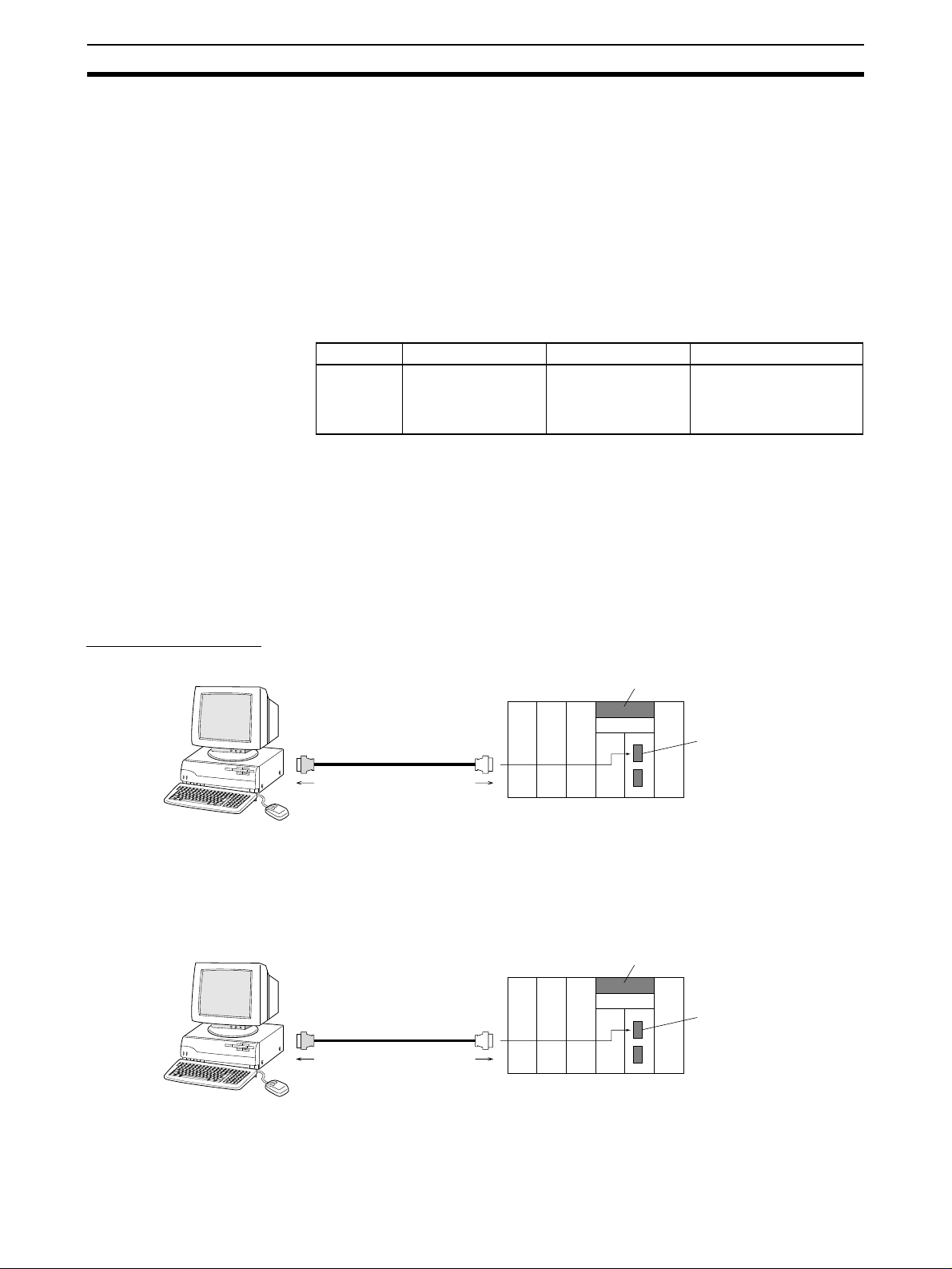
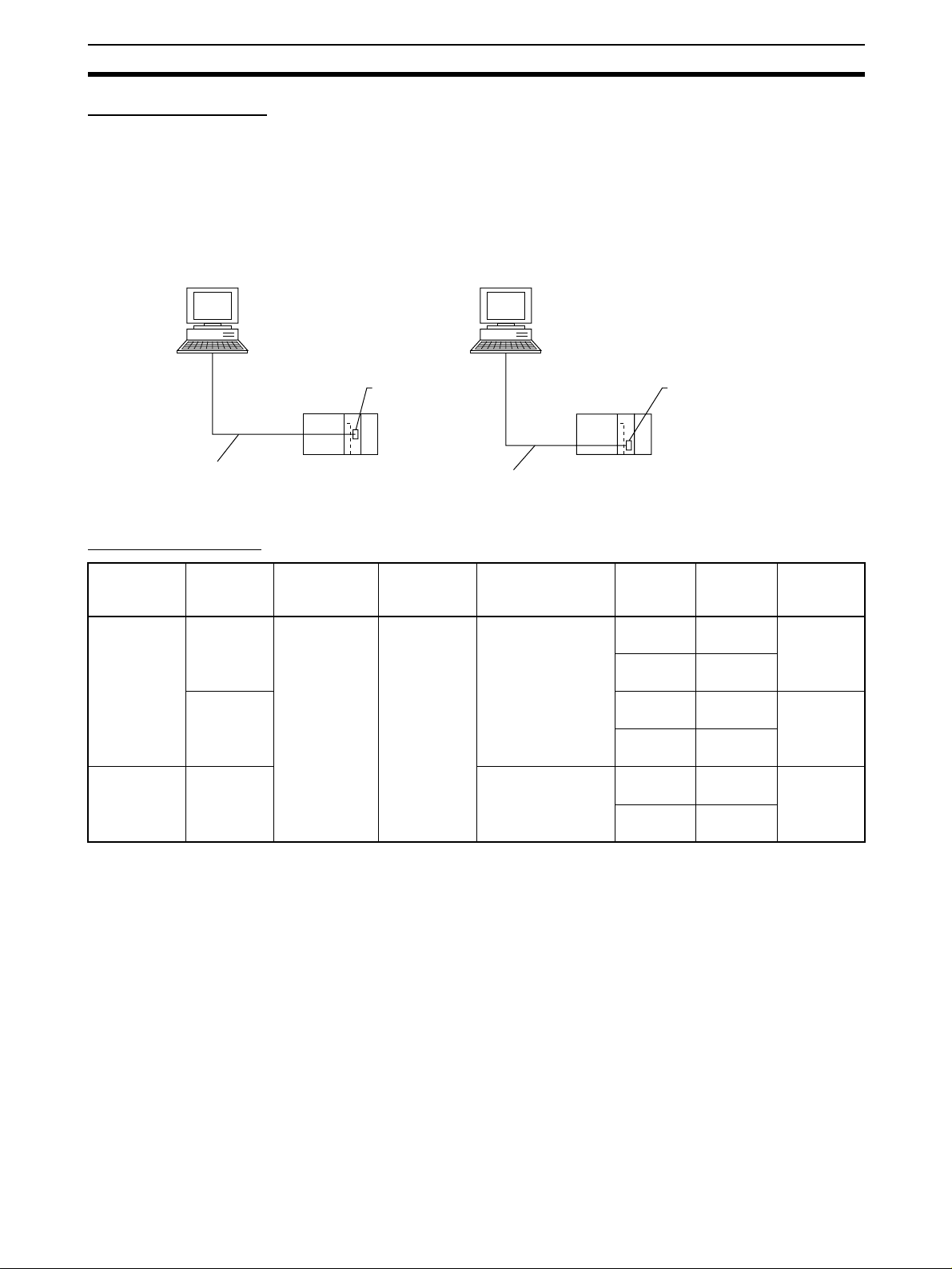
2-2-1 Connecting to CS/CJ-series PLCs
Connection Format • Connecting to the peripheral port on the CPU Unit
IBM PC/AT or compatible
P
C
-9
8
0
1
BX
N
E
C
RS-232C
Note To connect an IBM PC/AT or compatible to the CPU Unit, additional conver-
IBM PC/AT or compatible
Network type (serial
communications mode):
Toolbus or Host Link (for CS Series)
P
C
-9
8
0
1
BX
N
E
C
RS-232C RS-232C
Network type (serial
communications mode):
Toolbus or Host Link
To peripheral port
sion cables or connectors may be required. For details, see Connection
Method.
• Connecting to the RS-232C port on the CPU Unit
CPU Unit (e.g., CS-series)
CPU Unit (e.g., CS-series)
Peripheral port
RS-232C port
10
Note To connect an IBM PC/AT or compatible to the CPU Unit, additional conver-
sion cables or connectors may be required. For details, see Connection
Method.
Page 30
Connecting to a PLC Section 2-2
Connection Method The personal computer is connected to the peripheral port or the built-in RS-
232C port on the CPU Unit. Two network types, SYSMAC WAY (Host Link)
and Toolbus, are available.
Note With CS/CJ-series PLCs, a personal computer can be connected to ports on
Serial Communications Units/Boards. In this case, SYSMAC WAY (Host Link)
is the only supported network type.
Connecting Personal Computer (CX-Position) to CS/CJ-series CPU Units
Connecting to Peripheral Port
Connecting to RS-232C Port
IBM PC/AT or compatible
9-pin connector
CS1W-CN118 (0.1 m)
CS1W-CN226 (2.0 m)
CS1W-CN626 (6.0 m)
Connecting Cables
Unit Port on
Unit
CPU Unit Built-in
Serial
Communications
Board/Unit
peripheral
port
Built-in RS232C port
(D-sub, 9pin, female)
RS-232C
port
(D-sub, 9pin, female)
Peripheral port
on CPU Unit
Computer Port on com-
puter
IBM PC/AT or
compatible
D-sub, 9-pin,
male
IBM PC/AT or compatible
9-pin connector
XW2Z-200S-CV (2.0 m)
XW2Z-500S-CV (5.0 m)
Network type
(serial communi-
cations mode)
Toolbus or
SYSMAC WAY
(Host Link)
SYSMAC WAY
(Host Link)
Model
number
CS1WCN226
CS1WCN626
XW2Z200S-CV
XW2Z500S-CV
XW2Z200S-CV
XW2Z500S-CV
Built-in RS-232C port
on CPU Unit or Serial
Communications
Board/Unit
Length Remarks
2.0 m ---
6.0 m
2 m Uses
anti-static
5 m
2 m Uses
5 m
connector
anti-static
connector
Note When connecting the connectors of the above cables to the PLC’s RS-232C
port, discharge any static build-up (e.g., by touching a grounded metal object)
before touching the connectors. Although XW2Z-@@@S-CV Cables use the
anti-static XM2S-0911-E Connector Hood (thus reducing the possibility of
static build-up), be sure to discharge any static as a safety precaution.
11
Page 31

Connecting to a PLC Section 2-2
Other Connection
Methods
Connecting RS-232C
Cable to Peripheral Port
Unit Port on
Unit
CPU Unit Built-in
peripheral
port
The following connection methods can be used when connecting an RS-232C
cable to the peripheral port.
Computer Port on
IBM PC/AT or
compatible
computer
D-sub, 9-pin,
male
Network type
(serial communi-
cations mode)
Toolbus or SYSMAC
WAY (Host Link)
SYSMAC WAY
(Host Link)
Connect to
RS-232C port
RS-232C Cable
XW2Z-@@@S-@@
(See above.)
Model
number
CS1WCN118 +
XW2Z200S-CV/
500-CV
CS1WCN118 +
XW2Z200S-V/
500-V
CS1W-CN118
Length Remarks
0.1 m (2 m
or 5 m)
Peripheral port
The XW2Z@@@S-CV
uses an antistatic
connector.
---
Connecting
CQM1-CIF01/02 to
The following connection method can be used when connecting the conventional CQM1-CIF01/02 Cable to the peripheral port.
Peripheral Port
Unit Port on Unit Computer Port on
CPU Unit Built-in
peripheral
port
IBM PC/AT or
compatible
computer
D-sub, 9-pin,
male
Connect to
RS-232C port
Network type
(serial communica-
tions mode)
SYSMAC WAY (Host
Link)
CQM1-CIF01/CIF02
(Previous Peripheral Port
Connecting Cable)
Model
number
CS1WCN114 +
CQM1CIF02
Length Remarks
0.5 m +
3.3 m
CS1W-CN114
Peripheral port
---
12
Page 32

Connecting to a PLC Section 2-2
Connecting a Computer
with an RS-232C Cable
The following connection method can be used when connecting an IBM PC/
AT or compatible computer using an RS-232C cable.
Unit Port on Unit Computer Port on
CPU Unit Built-in RS-
232C port (Dsub, 9-pin,
IBM PC/AT
or
compatible
female)
Serial Communications
Board/Unit
RS-232C
port (D-sub,
9-pin, male)
Note When connecting an IBM PC/AT or compatible personal computer to the CPU
Unit using the USB port on the computer, use the CS1W-CIF31 USB-Serial
Conversion Cable (D-sub).
Making an RS-232C
Cable
For connections with an RS-232C cable, either purchase one of the cables
listed above, or make a cable using the connection method and components
given below.
Connector Pin
Arrangement
The pin arrangement for the CPU Unit connector is shown below.
Pin number Signal abbreviation Signal name Signal direction
1 FG Frame ground --2 SD (TXD) Send data Output
3 RD (RXD) Receive data Input
4 RS (RTS) Request to send Output
5 CS (CTS) Clear to send Input
6 5V Power supply --7 DR (DSR) Data set ready Input
8 ER (DTR) Data terminal ready Output
9 SG (0V) Signal ground --Metal cap FG Frame ground ---
computer
D-sub, 9-pin,
male
Network type
(serial communi-
cations mode)
SYSMAC WAY
(Host Link)
Model
number
XW2Z200S-V
XW2Z500S-V
XW2Z200S-V
XW2Z500S-V
Length Remarks
2 m ---
5m
2m
5m
CS-series Pin Arrangement
9
6
5
1
CJ-series Pin Arrangement
1
5
6
9
13
Page 33

Connecting to a PLC Section 2-2
Connection Method Either of the following configurations can be used for connection via Host Link.
CS/CJ-series
CPU Unit
Pin
Signal
No.
1
FG
2
SD
3
RS-232C
interface
RD
RS
CS
5V
DR
ER
SG
4
5
6
7
8
9
D-sub, 9-pin
(Cable connector: male)
CS/CJ-series
CPU Unit
Pin
Signal
No.
FG
1
SD
2
RD
RS-232C
interface
RS
CS
5V
DR
ER
SG
3
4
5
6
7
8
9
D-sub, 9-pin
(Cable connector: male)
IBM PC/AT or
compatible computer
Pin
Signal
No.
1
CD
2
RD
3
SD
RS-232C
ER
SG
DR
RS
CS
CI
interface
4
5
6
7
8
9
D-sub, 9-pin
(Cable connector: female)
IBM PC/AT or
compatible computer
Pin
Signal
No.
1
CD
2
RD
3
SD
RS-232C
ER
SG
DR
RS
CS
CI
interface
4
5
6
7
8
9
D-sub, 9-pin
(Cable connector: female)
Applicable Connectors Use the following connector at the CPU Unit end.
Product name Model number Specifications
Plug XM2A-0901 9-pin, male Use together.
Hood XM2S-0911-E For 9-pin, metric
screws
Anti-static
Use the following connector at the computer end (IBM PC/AT or compatible).
Product name Model number Specifications
Plug XM2D-0901 9-pin, female Use together.
Hood XM2S-0913 For 9-pin, Imperial
screws
Connect to an IBM PC/AT compatible computer using the following configuration.
IBM PC/AT or
compatible (9-pin, male)
Plug: XM2D-0901
(9-pin, female)
CS/CJ-series CPU Unit
(1 is provided with
CPU Units as a
standard accessory.)
RS-232C port
14
Recommended cable
Hood: XM2S-0913
Plug: XM2A-0901
Hood: XM2S-0911-E
Provided with CPU Unit as
standard accessories.
Page 34

Connecting to a PLC Section 2-2
Recommended Cables Fujikura Ltd.
UL2464 AWG28 × 5P IFS-RVV-SB (UL item)
AWG28
× 5P IFVV-SB (non-UL item)
Hitachi Cable, Ltd.
UL2464-SB (MA) 5P × 28AWG (7/0.127) (UL item)
CO-MA-VV-SB 5P
× 28AWG (7/0.127) (non-UL item)
2-2-2 Connecting to CP-series PLCs
Connecting to USB Port on CPU Unit with Commercially Available US Cable
Unit Port on Unit Computer Port on
computer
CPU Unit USB port
(B connector)
IBM PC/AT
compatible
USB port
(A connector)
Serial communi-
cations mode
(network type)
USB Commercially available
IBM PC/AT or
compatible
Model number Length Remarks
USB 1.1 or 2.0 cable
5 m
max.
---
USB port
CP-series CPU Unit
Commercially
available USB
cable
Peripheral
USB port
Connecting to RS-232C Port on Serial Communications Board with RS-232C Cable
Unit Port on
CP1W-CIF01
Serial Communications
Board
Unit
RS-232C
port, Dsub 9-pin
female
Computer Port on
computer
IBM PC/AT
compatible
D-sub, 9pin, male
Serial communi-
cations mode
(network type)
Toolbus (Peripheral) or SYSMAC
WAY (Host Link)
SYSMAC WAY
(Host Link)
Model number Length Remarks
XW2Z-200S-CV/500S-CV 2 m/5 m Uses anti-
static connector
XW2Z-200S-V/500S-V 2 m/5 m ---
15
Page 35

Connecting to a PLC Section 2-2
t
2-2-3 Connecting to CJ2 PLCs
USB or RS-232C Connection
Unit Port on Unit Computer Port on
computer
CPU Unit USB port
(B connector)
Built-in RS-
232C port, D-
IBM PC/AT
compatible
IBM PC/AT
compatible
USB port
(A connector)
D-sub 9-pin,
male
sub 9-pin
female
Note A Host Link (SYSMAC WAY) connection to an RS-232C port on the CPU Unit
or a Serial Communications Unit is not possible for CJ2 PLCs.
USB RS-232C
Serial communi-
Model number Length Remarks
cations mode
(network type)
USB Commercially available
USB 1.1 or 2.0 cable
Toolbus (See
XW2Z-200S-CV/500S-CV2 m/
note.)
5 m
max.
5 m
---
Uses
anti-static
connector
IBM PC/AT or
compatible
USB port
Commercially
available USB
cable
USB port
Ethernet Connection
Port on Unit Port on computer Serial communi-
cations mode
(network type)
Built-in EtherNet/
IP port
Ethernet port 100Base-TX/
10Base-T (Recommended:
100Base-TX)
CJ2 CPU Unit
IBM PC/AT or
compatible
CJ2 CPU Unit
D-sub connector
(9-pin male)
XW2Z-200S-CV/500S-CV
Connecting Cable
Serial port
(RS-232C):
D-sub connector
(9-pin female)
Model number Length Remarks
Commercially
available twisted
100 m (between
hub and node)
---
cable based on
EtherNet/IP standard
Commercially
--available switching hub
16
100Base-TX
twisted-pair cable
(straight)
IBM PC/AT or
compatible
Switching
hub
Built-in EtherNet/IP port
100Base-TX
twisted-pair cable
(straight)
CJ2 CPU Uni
Page 36

Basic Operations Section 2-3
2-3 Basic Operations
Descriptions of CX-Position’s basic operations are given below.
2-3-1 Starting
Select Start - Program - OMRON - CX-One - CX-Position - CX-Position.
The application will be started and the following window will be displayed.
2-3-2 Quitting
1,2,3... 1. Select File - Exit or click the Close Button at the top right corner of the win-
When the device type is set to a CS/CJ-series PLC or NSJ-series NSJ Controller, the CX-Position can also be started by right-clicking a Position Control
Unit in the I/O Table Window opened from the CX-Programmer that was
installed from the CX-One and selecting Start Special Application from
Start Only is selected from the submenu, the CX-Position will be started in
the same way as it is from the Windows Start Menu. If Start with Settings
Inherited is selected from the submenu, the CX-Position will be started using
the current device type setting, Position Control Unit model, and online/offline
status. (Creating a new project and adding a PLC and Position Control Unit
will also be performed automatically.)
dow. After editing a project, if the project has not been saved, the following
dialog box will be displayed.
2. Click the Yes Button to save the changes made. Click the No Button if it is
not necessary to save the changes. Click the Cancel Button to return to
the Project Editing Window without quitting CX-Position. Refer to 5-1 Sav-
ing Projects.
17
Page 37

Basic Operations Section 2-3
2-3-3 Basic Window
CX-Position’s Basic Window is shown below.
18
The Basic Window is split into 2 sections.
• The data hierarchy is displayed in tree format in the section on the left.
This section is called the project workspace.
• The section on the right contains project windows, which are displayed
when data icons in the project workspace are selected, when new data is
created, and when online operations are performed.
The menus that can be used with CX-Position are displayed on the menu bar.
The functions that can be used with CX-Position are displayed as icons on the
toolbar.
Page 38

Basic Operations Section 2-3
Windows
Project Workspace Data is displayed in the hierarchy shown below.
A Minus Icon appears next to data for
which the lower level is displayed. A Plus
Icon appears next to data for which the
lower level is not displayed.
If there is more than one PLC or Position Control Unit, then the corresponding
number of icons is displayed. One of each type of data file (e.g., parameters
and speeds) is registered for each Position Control Unit.
The Plus and Minus Icons can be used to display/hide sub-hierarchies. The
Plus Icon next to a data icon indicates that there is a hidden sub-hierarchy for
that data. Click the Plus Icon to display the sub-hierarchy. The Minus Icon
next to a data icon indicates that the sub-hierarchy for that data is displayed.
Click the Minus Icon to hide the sub-hierarchy.
The cursor can be moved up and down inside the project workspace when it
is active using the Up and Down Keys. If the Right Key is pressed when the
cursor is at a Plus Icon, the corresponding sub-hierarchy will be displayed. If
the Left Key is pressed when the cursor is at a Minus Icon, the cursor will
move to the next level up in the hierarchy.
Project Windows Project windows are displayed for data files selected from the project work-
space by double-clicking, and for online operations, such as transferring data
and monitoring Position Control Unit operation. The project workspace or
project windows can be made active simply by click the required window.
Project windows can also be made active by selecting Window - Project from
the menu bar.
19
Page 39

Basic Operations Section 2-3
2-3-4 Displaying Menus
If, for example, you click File, or press the Alt+F Keys, a menu will be dis-
played. Select functions from the menu by click the desired item.
Example: The following menu is displayed if you click File.
Shortcut keys are allocated to some functions. These allocations are displayed on the right side of the menu. For example, New can be selected by
pressing the Ctrl+N Keys (i.e., by pressing the N Key while holding down the
Ctrl Key).
If the menu is displayed, New can also be selected by pressing the N Key (i.e.,
the underlined letter).
2-3-5 Moving and Copying Position Control Unit Data
Position Control Unit data, such as parameters, sequences, and speeds, can
be moved to other Position Control Units in the same project in units of Position Control Units either using drag-and-drop or by using the Cut and Paste
commands. Data can also be copied using the Copy and Paste commands.
20
Page 40

Basic Operations Section 2-3
Moving Position Control
Unit Data
1,2,3... 1. Click the NC2 Icon, and move the cursor across to PLC 2 with the (left)
Position Control Unit data can be moved between CPU Units of the same
series. The following example shows how to move the data for NC2 on PLC1
to PLC2.
Either of the following 2 methods can be used.
■ Drag and Drop
mouse button held down. When the Position Control Unit Icon appears, release the mouse button.
The Position Control Unit Icon appears only if the data can be moved. If the
data cannot be moved, the Operation Prohibited Icon will be displayed.
■ Cut and Paste
1,2,3... 1. Select the NC2 Icon and execute the Cut command using any of the fol-
lowing methods:
• Right-click and select Cut from the pop-up menu.
•Select Edit - Cut from the menu bar.
• Click the Cut Icon in the toolbar.
2. Select the PLC2 Icon and paste the data using any of the following methods:
• Right-click and select Paste from the pop-up menu.
•Select Edit - Paste from the menu bar.
• Click the Paste Icon in the toolbar.
21
Page 41

Basic Operations Section 2-3
If there is a Position Control Unit with the same unit number at the PLC to
which NC2 is copied, the following dialog box will be displayed. Set a new unit
number (i.e., a unit number that is not used at that PLC). Changing this setting
will change the unit number of the Position Control Unit itself. The following
dialog box indicates that the unit number of NC2 is already used for another
Position Control Unit.
Copying Position Control
Unit Data
1,2,3... 1. Select the icon of the source Position Control Unit.
When data is copied from one Position Control Unit to another, the data at the
destination Position Control Unit is overwritten.
Position Control Unit data can be copied between CPU Units of the same
series.
If data is copied to a Position Control Unit that controls a higher number of
axes, only the data corresponding to the axes controlled by the source Position Control Unit is overwritten.
2. Copy the data using any of the following methods:
• Right-click and select Copy from the pop-up menu.
• Press the Ctrl+C Keys.
•Select Edit - Copy from the menu bar.
• Click the Copy Icon in the toolbar.
3. Select the icon of the destination Position Control Unit and paste the data
using any of the following methods:
• Right-click and select Paste from the pop-up menu.
• Press the Ctrl+V Keys.
•Select Edit - Paste from the menu bar.
• Click the Paste Icon in the toolbar.
22
4. Click the OK Button.
Page 42

Basic Operations Section 2-3
2-3-6 Main Menus
Main menu Contents Keyboard
shortcut
File Used to create, save, and print new projects. Alt+F
Edit Used to add or remove PLCs and Position Control
Units to/from projects, and edit Position Control Unit
data.
View Used to display or hide project trees, the toolbar, and
the scroll bar, and to switch between decimal and
hexadecimal display of Position Control Unit data.
Tool Used to make optional settings (font, number of files
displayed on the recently used file list, default display
format (decimal/hexadecimal)).
Online Used for performing online operations, such as down-
loading, uploading, comparison, and monitoring.
Window Used to change the display method for the currently
displayed editing window. It is also used to move the
focus from the data editing window to the project tree.
Help Used to display help and version information and to
perform online user registration.
Alt+E
Alt+V
Alt+T
Alt+L
Alt+W
Alt+H
23
Page 43

Basic Operations Section 2-3
2-3-7 Main Menu Items
The names and functions for all of the menus are given in the following table.
When an item is selected, the dialog box for that function is displayed. Follow
the instructions in the dialog box.
Main
menu
File New Creates a new project file. Ctrl+N
Edit New PLC Creates a new PLC for a project. ---
Item Contents Keyboard
Open Opens an existing project file. Ctrl+O
Close Project Closes the active project. --Close Closes the active data editing window. --Save Project Saves the active project (overwrites the
previous data).
Save Project As Saves the active project with a new
name.
Import Imports data created for the C200HW-
NC@13 with the SYSMAC-NT.
Print Prints all Position Control Unit data or
specified data.
Properties Displays the properties for a project,
PLC, or Position Control Unit.
Exit Quits CX-Position. ---
New NC Creates a new Position Control Unit for a
PLC.
Remove Removes a specified PLC or Position
Control Unit from a project.
Undo Undoes the previous operation. Ctrl+Z
Cut • Used to move a specified Position
Control Unit in the project tree to
another PLC.
• Used to move data in specified range
(other than parameter editing windows).
Copy • Used to copy data from a specified
Position Control Unit in the project
tree to another PLC’s Position Control
Unit.
• Used to copy specified data in a data
editing window.
Paste Copies the data copied to the clipboard
using Cut or Copy to a specified position.
Display All Displays all the data editing windows to
a specified Position Control Unit. If there
are already windows displayed, the
remaining windows are displayed. Up to
90 windows can open at the same time.
This command cannot be used if there
are 90 or more windows open.
Default Clear/Clear • The command Default Clear is dis-
played in parameter editing windows.
It returns the parameter settings for a
specified axis to their default values.
•The command Clear is displayed in
other windows. This command clears
specified data to 0.
Copy Axis Copies data in axis units. ---
shortcut
Ctrl+S
Ctrl+A
---
Ctrl+P
---
---
Del
Ctrl+X
Ctrl+C
Ctrl+V
---
---
24
Page 44

Basic Operations Section 2-3
Main
menu
View Project Displays/hides project tree. ---
Tool Option Displays the option dialog box. Used to
Online Download to NC Transfers specified data or all data to a
Item Contents Keyboard
Toolbar Displays/hides toolbar. --Status Bar Displays/hides status bar. --Change
Display
Upload from NC Transfers specified data or all data from
Verify Compares editing data with the data of a
Write Flash Memory
Monitor Monitors Position Control Unit operating
Monitor Units Simultaneously monitors the operating
Automatic NC
Search
Monitor NC Operating Memory Area
Monitor NC Operating Data Area
View NC Error Log Displays the error log for a specified
Test Run Executes JOG operations. --Test Run Settings Sets values to execute JOG operations. --Error Counter
Reset Output
Hexadecimal
Decimal Changes the display format for the
Changes the display format for the
active data editing window and the input
range display for the status bar to hexadecimal.
active data editing window and the input
range display for the status bar to decimal.
perform the following settings.
• Font name and size
• Default display format (decimal/hexadecimal) for data editing windows
• Number of files displayed on the
recently used files list (16 max.)
specified Position Control Unit.
a specified Position Control Unit to a
project.
specified Position Control Unit.
Writes Position Control Unit data to flash
memory.
status.
status for 4 Position Control Units.
Reads information about the Position
Control Units mounted to the PLC connected online, and automatically creates
a project based on this information. If the
Upload Data checkbox is selected, all
data for the Position Control Units
mounted to the specified PLC is read
and included in the project.
Monitors the commands, Position Control Unit status, I/O status, and error
codes allocated to the operating memory area.
Monitors the positions, speeds, acceleration/deceleration times, sequence
numbers, and present positions specified in the operating data area.
Position Control Unit.
Turns ON/OFF the error counter reset
output signal.
---
---
---
---
---
---
---
---
---
---
---
---
---
---
shortcut
25
Page 45

Basic Operations Section 2-3
Main
menu
Window Display All Displays all the data editing windows
Help Contents Displays the table of contents for help. ---
Item Contents Keyboard
---
that are represented as icons.
Icon All Displays all data editing windows as
icons.
Cascade Displays editing windows on top of each
Tile Horizontally Displays editing windows arranged hori-
Tile Vertically Displays editing windows arranged verti-
Arrange Icons Aligns editing windows represented as
Close All Closes all open editing windows. --Project Moves the focus to the project tree. ---
Search Displays the search window for help. --Unit Error Displays help for Unit errors. --Online Registra-
tion
Version Displays the version information for CX-
other.
zontally.
cally.
icons.
Connects to the CX-One website for
online software registration.
Position .
---
---
---
---
---
---
---
shortcut
26
Page 46

Basic Operations Section 2-3
2-3-8 Operations Listed by Purpose
Purpose Operation Keyboard
Project Creating a new
project
Opening a project File – Open Ctrl+O 5-2-1
Closing a project File – Close Project --- --- 2-3-2
Saving (overwriting) File – Save Project Ctrl+S 5-1-1
Saving with a different name
Importing File – Import --- --- 5-2-2
Printing File – Print Ctrl+P 10-1
Creating a new PLC Edit – New PLC
Creating a new Position Control Unit
Displaying the properties for a project,
PLC, or Position Control Unit
Removing a PLC or
Position Control Unit
Cutting a Position
Control Unit
Copying Position
Control Unit data
Pasting a Position
Control Unit
Pasting Position Control Unit data
Moving Position Control Unit data
Toolbar
shortcut
File – New Ctrl+N 3-1
File – Save Project As Ctrl+A --- 5-1-1
--- 3-2-1
or
Right-click and select New PLC.
Select a PLC and select Edit - New NC.
or
Select a PLC, right-click, and select New NC.
Select a PLC or Position Control Unit and select
File – Properties.
or
Select a PLC, right-click and select Properties.
Select a PLC or Position Control Unit and select
Edit – Remove.
or
Select a PLC or Position Control Unit, right-click,
and select Remove.
Select a Position Control Unit and select Edit –
Cut.
or
Select a Position Control Unit, right-click, and
select Cut.
Select a Position Control Unit and select Edit –
Copy.
Select a PLC and select Edit – Paste.
or
Select a PLC, right-click, and select Paste.
Select a Position Control Unit and select Edit –
Paste.
or
Select a Position Control Unit, right-click, and
select Paste.
Drag the Position Control Unit using the mouse
and drop it at the desired PLC.
--- 3-3-1
--- --- 3-1
DEL 3-2-2,
Ctrl+X 2-3-5
Ctrl+C 2-3-5
Ctrl+V 2-3-5
Ctrl+V 2-3-5
--- --- 2-3-5
icon
Refer-
ence
section
3-3-2
27
Page 47

Basic Operations Section 2-3
Display
settings
Editing
data
Purpose Operation Keyboard
Displaying/hiding a
project
Displaying/hiding the
toolbar
Displaying/hiding the
status bar
Switching between
decimal and hexadecimal display
Opening all editing
windows
Editing parameter
data
Editing sequence
data
Editing speed data • Select Edit Speeds in the project and double-
Editing acceleration/
deceleration data
Editing dwell time
data
Editing zone data • Select Edit Zone in the project and double-
Initializing the data in
a specified range
Copying the data in a
specified range
Pasting the data in a
specified range
Undoing the last
operation
Returning parameter
data to default settings
View – Project --- --- 2-3-12
View – Toolbar --- --- 2-3-12
View – Status Bar --- --- 2-3-12
• View – Change Display – Decimal or Hexa-
decimal
• Right-click in editing window and select Decimal or Hexadecimal
• Select a Position Control Unit in the project
and select Edit – Display All
• Select a Position Control Unit in the project,
right-click and select Display All
• While data editing, select Edit – Display All
•Select Edit NC Parameters in the project and
double-click.
•Select Edit NC Parameters in the project and
click the Enter Button.
•Select Edit Sequence in the project and dou-
ble-click.
•Select Edit Sequence in the project and click
the Enter Button.
click.
•Select Edit Speeds in the project and press
Enter.
•Select Edit Accel/Decel in the project and
double-click.
•Select Edit Accel/Decel in the project and
click the Enter Button.
•Select Edit Dwell Time in the project and dou-
ble-click.
•Select Edit Dwell Time in the project and click
the Enter Button.
click.
•Select Edit Zone in the project and click the
Enter Button.
Edit – Cut Ctrl+X ---
Edit – Copy Ctrl+C ---
Edit – Paste Ctrl+V ---
Edit – Undo Ctrl+Z ---
Edit – Default Clear
or
In an editing window, right-click and select
Default Clear.
(Parameter editing windows only)
shortcut
--- 2-3-12,
--- --- 4-2-1
--- --- 4-3-2
--- --- 4-4
--- --- 4-5
--- --- 4-6
--- --- 4-7
--- --- 4-8
--- --- 4-2-4
Toolbar
icon
Refer-
ence
section
4-2-3
28
Page 48

Basic Operations Section 2-3
Editing
data
Online
operations
Option settings
Displaying
help
Purpose Operation Keyboard
Clearing data in a
specified range to 0
Copying data to
another axis
Downloading Online – Download to NC --- 6-3
Uploading Online – Upload from NC --- 6-4
Verification Online – Verify --- 6-5
Writing to flash memory
Monitoring a Position
Control Unit
Monitor Units Online – Monitor Units --- 7-2
Automatic setting of
project
Monitoring operating
memory area
Monitoring operating
data area
Displaying an error
log
Te s t R u n Online – Test Run --- --- 8-2
Test Run Settings Online – Test Run Settings --- --- 8-1
Error Counter Reset
Output
Making font settings Tool – Option – Font --- --- 2-3-11
Setting the default
display format
Setting the number of
files displayed in the
recently used files list
Displaying help table
of contents
Searching for help
topics
Displaying help for
Unit errors
Registering online Help – Online Registration --- --- 2-3-13
Displaying CX-Posi-
tion version information
Edit – Clear
or
In an editing window, right-click and select Clear
(Windows other than parameter editing windows)
Edit – Copy Axis --- --- 4-2-5
Online – Write Flash Memory --- 6-6
Online – Monitor --- 10-1
Online – Automatic NC Search --- --- 6-4-2
Online – Monitor NC Operating Memory Area --- --- 7-3
Online – Monitor NC Operating Memory Area --- --- 7-4
Online – View NC Error Log --- --- 11-1-2
Online – Error Counter Reset Output --- --- 9-1
Tool – Option – Default Display Format --- --- 2-3-11
Tool – Option – Number of recent used files --- --- 2-3-11
Help – Contents --- --- 2-3-13
Help – Search --- --- 2-3-13
Help – Unit Error --- --- 2-3-13
Help – Version --- --- 2-3-13
shortcut
--- --- 4-2-4
Toolbar
icon
Refer-
ence
section
29
Page 49

Basic Operations Section 2-3
2-3-9 Toolbar
Functions can be executed directly by click the appropriate icon on the toolbar. The functions that can be executed from the toolbar are given below.
1 2 3 4 5 6 7 8 9 10 11 12 13 14 15 16 17 18 19
Number Function Number Function
1 Creates a new project. 11 Inserts the clipboard con-
2 Opens an existing project. 12 Download
3 Saves the active project. 13 Upload
4 Print 14 Verify
5 Adds a new PLC. 15 Writes to flash memory
6 Adds a new Position Control
Unit.
7 Delete 17 Monitors operating status
8 Undo 18 Changes display format to
9 Cuts the selection and moves it
to the clipboard.
10 Copies the selection and
moves it to the clipboard.
16 Monitors Position Control
19 Changes display format to
tents at the insertion point.
Unit operating status.
for 4 Position Control Units.
decimal.
hexadecimal.
2-3-10 Status Bar
The following information is displayed on the status bar.
• Network information or Position Control Unit’s unit No.
• PLC or Position Control Unit model
• Communications mode (offline/online)
• When inputting data, the range that can be input is displayed here. Help is displayed at other times.
30
Page 50

Basic Operations Section 2-3
2-3-11 Option Settings
The following settings can be made as option settings.
• Name and size of font for data editing windows
• Default display format for data editing windows
• Number of files displayed in the recently used files list
Setting the Font Name and
Size
1,2,3... 1. Select Tool - Option. The Option Dialog Box is displayed.
Setting the Default
(Startup) Display Format
1,2,3... 1. Select Tool - Option. The Option Dialog Box will be displayed.
Setting the Number of
Files Displayed in the
Recently Used Files List
1,2,3... 1. Select Tool - Option. The Option Dialog Box will be displayed.
2. Click the Change Font. Button. The Change Font Dialog Box will be displayed.
3. After selecting the desired font name and size from the drop-down lists,
click the OK Button.
2. Under Default Display Format, select either Hexadecimal display or
Decimal display.
2. Under Numbers of recent used files, either enter a number directly or select a number from the drop-down list.
31
Page 51

Basic Operations Section 2-3
2-3-12 View Settings
The view settings can be used to display or hide the project tree, the toolbar,
or the status bar, or change the display format (decimal/hexadecimal) for the
active data editing window.
Display/Hide Settings
1,2,3... 1. Click View.
2. If a check appears next to Project, Toolbar, or Status Bar, the corre-
sponding item is displayed. To hide any of these, select Project, Toolbar,
or Status Bar to remove the check.
Setting the Display Format Data in the active data editing window can be displayed in either decimal or
hexadecimal. The default display format is set in the option settings.
1,2,3... 1. Select the data for which the display format is to be changed, and either
right-click or select View - Change display.
2-3-13 Help
Displaying the Help
Contents
2. Select either Hexadecimal or Decimal as desired.
Note 1. The display format can also be changed by right-clicking in the editing win-
dow, and selecting either Decimal or Hexadecimal from the pop-up menu.
2. Hexadecimal cannot be used if the unit setting is either millimeter or inch.
Use decimal display.
1,2,3... 1. Select Help - Contents. The table of contents for help will be displayed.
32
Page 52

Basic Operations Section 2-3
2. Select an item to display information relating to that item.
Searching by Key Word
1,2,3... 1. Select Help - Search. The Help Topics Dialog Box will be displayed.
2. Enter the first few letters of the word to be searched for and press Enter or
click the Display Button. If a matching word is found, it is highlighted. Select Display or double-click to display the information for that word.
33
Page 53

Basic Operations Section 2-3
It is also possible to click directly on a key word (index entry) and then click
the Display Button or double-click to display the information for that word.
Displaying Unit Errors Use the following procedure to display help for Position Control Unit errors.
1,2,3... 1. Select Help - Unit Error. The Error Code Help Dialog Box will be dis-
played.
34
Page 54

Basic Operations Section 2-3
2. Click the relevant error code. Information about that error code will be displayed.
Registering CX-Position Online
1,2,3... 1. Select Help - Online Registration. The OMRON CX-One website will be
Note The Product Key and Licence Number listed in the Licence Agreement will be
Displaying CX-Position
Version Information
displayed.
2. Enter user information as directed on the screen.
required for online user registration.
Select Help - Version. The CX-Position version information will be displayed.
35
Page 55

Basic Operations Section 2-3
36
Page 56

SECTION 3
Creating New Projects
This section describes the procedures for creating new projects, as well as those for adding and deleting Programmable
Controllers (PLCs) and Position Control Units (NC Units).
3-1 Creating New Projects. . . . . . . . . . . . . . . . . . . . . . . . . . . . . . . . . . . . . . . . . . . 38
3-2 Adding and Deleting PLCs . . . . . . . . . . . . . . . . . . . . . . . . . . . . . . . . . . . . . . . 40
3-2-1 Adding a PLC . . . . . . . . . . . . . . . . . . . . . . . . . . . . . . . . . . . . . . . . . . 40
3-2-2 Deleting a PLC . . . . . . . . . . . . . . . . . . . . . . . . . . . . . . . . . . . . . . . . . 43
3-3 Adding and Deleting Position Control Units . . . . . . . . . . . . . . . . . . . . . . . . . 44
3-3-1 Adding a Position Control Unit . . . . . . . . . . . . . . . . . . . . . . . . . . . . 44
3-3-2 Deleting a Position Control Unit . . . . . . . . . . . . . . . . . . . . . . . . . . . 44
3-4 Automatic Position Control Unit Search . . . . . . . . . . . . . . . . . . . . . . . . . . . . 45
37
Page 57

Creating New Projects Section 3-1
3-1 Creating New Projects
Starting CX-Position from the Windows Start Menu, or by Selecting Start Special Application - Start
Only from the Pop-up Menu in I/O Table Window Opened from the CX-Programmer That Was Installed
from the CX-One
Use the following procedure to create a new project.
1,2,3... 1. Select File - New, press the Ctrl+N Keys, or select the New Project Icon
from the toolbar.
2. To change the project name, highlight the project and either select File -
Properties, or right-click and select Properties from the pop-up menu.
New Project is the default project name.
3. Enter the project name and click the OK Button. Comments can also be
entered.
38
Page 58

Creating New Projects Section 3-1
Starting CX-Position by Selecting Start Special Application - Start with Settings Inherited from the Popup Menu in I/O Table Window Opened from the CX-Programmer That Was Installed from the CX-One
1,2,3... 1. Right-click a Position Control Unit in the I/O Table Window and select Start
Special Application - Start with Settings Inherited from the popup
menu.
Example: Right-click the Position Control Unit (e.g., CJ1W-NC133)
Select Start Special Application.
Then select Start with Setting Inherited.
2. The CX-Position will be started, a new project will be created, and a Position Control Unit will be added automatically. The PLC information, Position
Control Unit model, and unit number will be inherited as shown below.
PLC information inherited from I/O tables.
Position Control Unit information
inherited from I/O tables under
the name TargetSIOU.
Note Even if there is more than one Position Control Unit in the I/O tables, informa-
tion can be inherited by the CX-Position from only one of them.
39
Page 59

Adding and Deleting PLCs Section 3-2
3-2 Adding and Deleting PLCs
3-2-1 Adding a PLC
Use the following procedure to add a PLC to a new or existing project.
1,2,3... 1. Select the project from the project tree, and either select Edit - New PLC
or right-click and select New PLC from the pop-up menu. The Add PLC Dialog Box will be displayed.
2. Enter the Device Name.
Note Use one-byte characters for the device name, except for the ones
listed below and blank characters.
! “ # $ % & ‘ ( ) = - ~ ^ ¥ | ’ @ { [ + ; * : } ] < , > . ? /
If [ or ] is used in the device name for PLCs functioning as gateways, the network address for the PLC on the gateway network will
be 0. This will prevent communications with Position Control Units
on the gateway network.
3. Set the PLC Device Type by click the PLC Device Type drop-down list and
selecting the device type.
4. Click the Settings Button on the right of the Device Type box. The Device
Type Setup Dialog Box will be displayed. Click the CPU Type drop-down
list, select an applicable CPU type from the list, and click OK.
40
5. Set the network type. Select either SYSMC WAY (Host Link) or Toolbus.
6. Enter a comment if required.
7. Click the Settings Button on the right of Network Type Selection box.
Page 60

Adding and Deleting PLCs Section 3-2
■ When SYSMAC WAY (Host Link) Has Been Selected
The following Network Settings Dialog Box will be displayed as shown.
Setting the Network Tab Page
FINS Remote Address
This setting is required when going online with Position Control Unit mounted
on a PLC in the network. Use the default setting (Network: 0, Node: 0). For the
setting to go online with the PLC in the network, refer to 6-2-2 Connecting to
PLCs on Networks.
Frame Length
Use the default setting. When using 2 or more types of networks, use the
shorter frame length among them.
Response Timeout (s)
When timeouts occur in online operations, increase the value set for response
timeout (s).
Note • The response timeout can be set to between 1 s and 600 s. When a value
exceeding the range is set, it will be automatically adjusted so that it is
within the range.
• Setting a response timeout shorter than 10 s may cause timeouts.
• Although the response timeout can be set to up to 600 s, online operations (monitoring, device info, etc.) cannot be canceled once started.
Therefore, when setting a larger value for the response timeout, make
sure that it will not cause any problems even without operations from the
CX-Position.
Host Link Unit No.
Set the unit number of the Host Link port connected to the port on the computer. When the unit number of the Host Link port has been changed, set the
applicable number.
41
Page 61

Adding and Deleting PLCs Section 3-2
Setting the Driver Tab Page
Set the Connection and Data Format. The communications settings here
have to be the same as in the PLC Setup on CPU Unit. For details, refer to the
operation manual of the CPU Unit being used.
The Modem Tab Page is used for the modem connection settings. The CXPosition can be connected to PLCs through a modem. For details on modem
connections, refer to the CX-Programmer Ver. 5.0 Operation Manual (W437)
and CX-Programmer Ver. 6.1 Operation Manual (W446).
■ When Toolbus Has Been Selected
Setting the Network Tab Page
For various settings, see When SYSMAC WAY (Host Link) Has Been
Selected for reference.
42
Page 62

Adding and Deleting PLCs Section 3-2
Setting the Driver Tab Page
Baud rate auto-detect can be enabled here, communications are established
with the baud rate set here regardless of the communications setting on the
CPU Unit.
8. Click the OK Button to add the PLC to the project.
3-2-2 Deleting a PLC
1,2,3... 1. Select the PLC to be deleted from the project tree, and select Edit - Re-
move DEL, press the DEL Key, or right-click and select Remove - DEL
from the pop-up menu.
2. A dialog box will be displayed asking “Do you want to delete?” Click the OK
Button.
43
Page 63

Adding and Deleting Position Control Units Section 3-3
3-3 Adding and Deleting Position Control Units
3-3-1 Adding a Position Control Unit
Use the following procedure to add a Position Control Unit to a PLC.
1,2,3... 1. Select the PLC to be added to from the project tree.
2. Either select Edit - New NC, or right-click and select New NC from the popup menu.
3. Enter the NC Name. New NC@ (where @ = 1, 2 etc.) is the default name.
4. Set the NC Type by click the NC Type drop-down list and selecting.
5. Select the Unit No. allocated to the Position Control Unit (as a Special I/O
Unit)
6. Enter a comment if required.
7. Click the OK Button to add the Position Control Unit to the project.
3-3-2 Deleting a Position Control Unit
1,2,3... 1. Select the Position Control Unit to be deleted from the project tree, and se-
lect Edit - Remove DEL, press the DEL Key, or right-click and select Re-
move - DEL from the pop-up menu.
2. A dialog box will be displayed asking “Do you want to delete?” Click the OK
Button.
44
Page 64

Automatic Position Control Unit Search Section 3-4
3-4 Automatic Position Control Unit Search
When online, data from all the Position Control Units mounted in the online
PLC can be read to automatically create NCs within a specified PLC. At the
same time, all the data read from the Position Control Units of the specified
PLC can added as project data.
1,2,3... 1. Create a PLC by either select Edit - New PLC, or right-click and select
New PLC from the pop-up menu.
2. Select the PLC from the project tree and then select Online - Automatic
NC Search.
The Automatic NC Search Dialog Box, shown above, will be displayed.
3. Select the data upload checkbox to read all the data from the Position Control Units.
4. Click the OK Button to create NCs automatically. If there is data to be uploaded, the following window will appear.
If there is no data to be uploaded, the following window will appear.
45
Page 65

Automatic Position Control Unit Search Section 3-4
46
Page 66

SECTION 4
Editing Settings
This section describes the procedures used to edit settings. This manual describes on the possible range of settings and
setting procedures. Refer to the Operation Manuals for individual Position Control Units for details on the settings.
4-1 Overview. . . . . . . . . . . . . . . . . . . . . . . . . . . . . . . . . . . . . . . . . . . . . . . . . . . . . 48
4-2 Setting Editing Windows. . . . . . . . . . . . . . . . . . . . . . . . . . . . . . . . . . . . . . . . . 51
4-2-1 Displaying Setting Editing Windows . . . . . . . . . . . . . . . . . . . . . . . . 52
4-2-2 Editing Settings. . . . . . . . . . . . . . . . . . . . . . . . . . . . . . . . . . . . . . . . . 56
4-2-3 Switching Setting Display Formats . . . . . . . . . . . . . . . . . . . . . . . . . 58
4-2-4 Clearing Settings. . . . . . . . . . . . . . . . . . . . . . . . . . . . . . . . . . . . . . . . 58
4-2-5 Copying Axis Settings . . . . . . . . . . . . . . . . . . . . . . . . . . . . . . . . . . . 59
4-3 Editing Parameter Settings . . . . . . . . . . . . . . . . . . . . . . . . . . . . . . . . . . . . . . . 60
4-3-1 Parameter Setting Editing Window. . . . . . . . . . . . . . . . . . . . . . . . . . 60
4-3-2 Editing Parameter Settings . . . . . . . . . . . . . . . . . . . . . . . . . . . . . . . . 60
4-4 Editing Sequence Settings. . . . . . . . . . . . . . . . . . . . . . . . . . . . . . . . . . . . . . . . 61
4-4-1 Sequence Editing Window . . . . . . . . . . . . . . . . . . . . . . . . . . . . . . . . 61
4-4-2 Editing Sequence Settings . . . . . . . . . . . . . . . . . . . . . . . . . . . . . . . . 62
4-5 Editing Speed Settings . . . . . . . . . . . . . . . . . . . . . . . . . . . . . . . . . . . . . . . . . . 63
4-5-1 Speed Setting Editing Window. . . . . . . . . . . . . . . . . . . . . . . . . . . . . 63
4-5-2 Editing Speed Settings . . . . . . . . . . . . . . . . . . . . . . . . . . . . . . . . . . . 63
4-6 Editing Acceleration/Deceleration Time Settings. . . . . . . . . . . . . . . . . . . . . . 64
4-6-1 Acceleration/Deceleration Time Setting Window . . . . . . . . . . . . . . 64
4-6-2 Editing Acceleration/Deceleration Time Settings . . . . . . . . . . . . . . 64
4-7 Editing Dwell Time Settings. . . . . . . . . . . . . . . . . . . . . . . . . . . . . . . . . . . . . . 65
4-7-1 Dwell Time Setting Window . . . . . . . . . . . . . . . . . . . . . . . . . . . . . . 65
4-7-2 Editing Dwell Time Settings. . . . . . . . . . . . . . . . . . . . . . . . . . . . . . . 65
4-8 Editing Zone Settings . . . . . . . . . . . . . . . . . . . . . . . . . . . . . . . . . . . . . . . . . . . 66
4-8-1 Zone Setting Window . . . . . . . . . . . . . . . . . . . . . . . . . . . . . . . . . . . . 66
4-8-2 Editing Zone Settings . . . . . . . . . . . . . . . . . . . . . . . . . . . . . . . . . . . . 66
47
Page 67

Overview Section 4-1
4-1 Overview
There are 6 types of settings used in CS1W-NC@@3/CJ1W-NC@@3 Position
Control Units. Setting items, setting ranges and default values are shown in
the following table.
Refer to the following operation manuals for details on specific settings.
Reference Manuals:
• SYSMAC CS1W-NC113/133/213/233/413/433 Position Control Units
Operation Manual (
• SYSMAC CJ1W-NC113/133/213/233/413/433 Position Control Units
Operation Manual (
Parameters
Item Setting range Default setting
Unit set (unit setting) Pulse, mm, or inches Pulse
Pulse rate 0.0001 to 1.0000 (See note 1.) 1.0000
Output pulse selection CW/CCW output or pulse/direction output CW/CCW output
Output pulse direction (See note 2.) Not reversed/Reversed Not reversed
Limit input sig type (limit input signal
type)
Ori prox sig type (origin proximity signal
type)
Ori sig type (origin signal type) N.C. or N.O. N.O.
Emerg stop fun (emergency stop func-
tion)
Non-origin setting (no origin setting) Retain prior status or forcibly change to origin undefined sta-
Set operation mode (operating mode
setting)
Ori search operation (origin search
operation) (See note 3.)
Ori search method Method 0, Method 1, Method 2, or Method 3 Method 0
Ori search dir (origin search direction) Clockwise (CW) or counterclockwise (CCW) CW
Position-preset origin search
(See note 2.)
Top speed (See notes 4 and 5.) 00000001 to 0007A120 Hex (1 to 500,000 pps) 0007A120
Start speed (See notes 4 and 5.) 00000000 to 0007A120 Hex (0 to 500,000 pps) 00000000 (0)
Ori search high speed
(See notes 4 and 5.)
Ori search low speed
(See notes 4 and 5.)
Ori compensation value (origin com-
pensation value) (See notes 4 and 5.)
Backlash comp (backlash compensa-
tion) (See notes 4 and 5.)
Backlash speed (See notes 4 and 5.) 00000000 to 0007A120 Hex (0 to 500,000 pps) 00000000 (0)
Acc/Dec curve (acceleration/decelera-
tion curve) (See note 6.)
Acc/Dec time specification (Accelera-
tion/Deceleration time specification)
(See note 4.)
Acc time (acceleration time)
(See note 4.)
Dec time (deceleration time)
(See note 4.)
N.C. or N.O. N.C.
N.C. or N.O. N.O.
Only pulse output or error counter reset Only pulse output
tus
Mode 0, Mode 1, Mode 2, or Mode 3 Mode 0
Reverse mode 1, Reverse mode 2, Single-direction mode, or
Reverse mode 3
Disabled/Enabled Disabled
00000001 to 0007A120 Hex (1 to 500,000 pps) 000061A8
00000001 to 0007A120 Hex (1 to 500,000 pps) 000009C4 (2,500)
C0000001 to 3FFFFFFF Hex (±1,073,741,823 pulses) 00000000 (0)
0000 to 270F Hex (0 to 9,999 pulses) 0000 (0)
Trapezoid or S-curve Trapezoid
Maximum speed interval/Target speed interval Maximum speed
00000000 to 0003D090 Hex (0 to 250,000 ms) 00000064 (100)
00000000 to 0003D090 Hex (0 to 250,000 ms) 00000064 (100)
W376)
W397)
Retain prior status
Reverse mode 1
(500,000)
(25,000)
interval
48
Page 68

Overview Section 4-1
Item Setting range Default setting
Positioning mon time (positioning monitor time) (See note 4.)
CCW limit (See notes 4 and 5.) C0000001 to 3FFFFFFF Hex (±1,073,741,823 pulses) C0000001
CW limit (See notes 4 and 5.) C0000001 to 3FFFFFFF Hex (±1,073,741,823 pulses) 3FFFFFFF
Initial pulse specification 250 pps or top speed 250 pps
Notes 1. Always 1 if the unit is set to Pulse.
0000 to 270F Hex (0 to 9,999 pulses) (See note 7.) 270F (9,999)
(−1,073,741,823)
(+1,073,741,823)
2. If these parameters are not set to their default settings, it will not be possible to download parameters to a Pre-version 2.0 Position Control Unit or a
Position Control Unit with a unit version of 2.1 or earlier (with embedded
software version 2.1 or lower). These parameter cannot be set with CX-Position version 2.0 or lower.
3. If reverse mode 3 is set, it will not be possible to download parameters to
a Pre-version 2.0 Position Control Unit or a Position Control Unit with a unit
version of 2.1 or earlier (with the embedded software version 2.1 or lower).
Reverse mode 3 cannot be set with CX-Position version 2.0 or lower.
4. Settings can be entered and displayed in either hexadecimal or decimal
format depending on the setting of the display format.
5. Ranges given in the table are for when the displayed value’s unit is set to
Pulse. When the set unit is millimeters or inches and the pulse rate is set
to a value other than 1, the values displayed will change to the specified
set value
× the pulse rate. The following settings are also affected:
•Position
• Zone
• Speed
6. Setting the target speed interval on a Pre-version 2.0 Position Control Unit
(with embedded software version 1.00) will cause an error when data is
downloaded from the personal computer to the Position Control Unit. Use
the default setting of maximum speed interval. Refer to information on unit
versions at the front of this manual for the relationship between the unit version of the Position Control Unit and the version of the embedded system
software, and the confirmation methods.
7. The position monitoring time must be set only when the operating mode is
set to Mode 2 or Mode 3.
Sequences (X/Y/Z/U Axes:
#0 to #99)
Only the X-axis settings are used for the CS1W-NC113/133 and CJ1WNC113/133, and only the X- and Y-axis settings are used for the CS1WNC213/233 and CJ1W-NC213/233. Settings can be entered in either hexadecimal or decimal format depending on display setting.
Item Setting range
Position data C0000001 to 3FFFFFFF Hex (±1,073,741,823 pulses)
Axis set X/Y/Z/U
Output code
(See note 1.)
Position designation 0 (absolute position) or 1 (relative position)
End code (comple-
tion code)
(See note 1.)
Dwell # (See note 1.) 00 to 13 Hex (0 to 19)
00 to 0F Hex (0 to 15)
00 to 06 Hex (0 to 6)
49
Page 69

Overview Section 4-1
Item Setting range
Accel. #
(See note 1.)
Decel. #
(See note 1.)
Start speed
(See note 1.)
Target speed
(See note 1.)
Notes 1. These values can be entered and displayed in either hexadecimal or dec-
imal format by setting the display format.
2. Ranges given in the table are for when the displayed value’s unit is set to
Pulse. When the set unit is millimeters or inches and the pulse rate is set
to a value other than 1, the values displayed will change to the specified
set value
× the pulse rate.
0 to 9 Hex (0 to 9)
0 to 9 Hex (0 to 9)
00 to 63 Hex (0 to 99)
00 to 63 Hex (0 to 99)
Speeds (X/Y/Z/U Axes: #0
to #99)
Notes 1. Settings can be entered and displayed in either hexadecimal or decimal
Acceleration/Deceleration
(X/Y/Z/U Axes: #1 to #9)
Only the X-axis settings are used for the CS1W-NC113/133 and CJ1WNC113/133, and only the X- and Y-axis settings are used for the CS1WNC213/233 and CJ1W-NC213/233. Settings can be entered and displayed in
either hexadecimal or decimal format depending on the setting of the display
format.
Item Setting range
Speed (See notes 1 and 2.) 00000000 to 000F4240 Hex (0 to 1,000,000) (pps)
format depending on the setting of the display format.
2. When the displayed value’s set unit is Pulse. When the set unit is mm or
inches and the pulse rate is set to other than 1, the value displayed will
change.
3. The speeds set above can be set as interpolation speeds. However, make
sure that the maximum speed of individual axes does not exceed
500,000 (pps) or the maximum speed set in the parameter settings.
Only the X-axis settings are used for the CS1W-NC113/133 and CJ1WNC113/133, and only the X- and Y-axis settings are used for the CS1WNC213/233 and CJ1W-NC213/233. Settings can be entered and displayed in
either hexadecimal or decimal format depending on the setting of the display
format.
Item Setting range
Acceleration (See note.) 00000000 to 0003D090 Hex (0 to 250,000) (ms)
Deceleration (See note.) 00000000 to 0003D090 Hex (0 to 250,000) (ms)
Note Settings can be entered and displayed in either hexadecimal or decimal for-
Dwell Time (X/Y/Z/U Axes:
#1 to #19)
Note Settings can be entered and displayed in either hexadecimal or decimal for-
50
mat depending on the setting of the display format.
Only the X-axis settings are used for the CS1W-NC113/133 and CJ1WNC113/133, and only the X- and Y-axis settings are used for the CS1WNC213/233 and CJ1W-NC213/233. Settings can be entered and displayed in
either hexadecimal or decimal format depending on the setting of the display
format.
Item Setting range
Dwell time (See note.) 0000 to 03E7 Hex (0.00 to 9.99) (s)
mat depending on the setting of the display format.
Page 70

Setting Editing Windows Section 4-2
Zone (X/Y/Z/U Axes: Zone
0 to Zone 2)
Note 1. Settings can be entered and displayed in either hexadecimal or decimal
Only the X-axis settings are used for the CS1W-NC113/133 and CJ1WNC113/133, and only the X- and Y-axis settings are used for the CS1WNC213/233 and CJ1W-NC213/233. Settings can be entered and displayed in
either hexadecimal or decimal format depending on the setting of the display
format.
Item Setting range
Zone
(See notes 1 and 2.)
format depending on the setting of the display format.
2. When the displayed value’s set unit is Pulse. When the set unit is mm or
inches and the pulse rate is set to other than 1, the value displayed will
change to specified set value
4-2 Setting Editing Windows
Use the following procedures to display the window shown below.
To create a new project:
•Select File- New; or
• Press the Ctrl+N Keys; or
• Select the New Project Icon from the toolbar.
To select an existing project:
•Select File - Open; or
• Press the Ctrl+O Keys; or
• Select the Open Icon from the toolbar.
C0000001 to 3FFFFFFF Hex (±1,073,741,823) (pulses)
× Pulse Rate.
Note Refer to SECTION 5 Saving and Reading Projects for information on opening
an existing project
Example: The following window will be displayed after creating a new project
51
Page 71

Setting Editing Windows Section 4-2
4-2-1 Displaying Setting Editing Windows
Use the following procedures to display individual Setting Editing Windows in
project window.
To Display Individual
Setting Editing
Windows
To Display the Parameter
Editing Window
1,2,3... 1. Under the NC on the project tree, either double-click Edit NC Parameters,
With the project tree displayed, select the settings to be displayed for the
specified NC, and either double-click or press the Enter Key.
X- and Y-axis editing windows will be displayed for 2-axis Position Control
Units; X-, Y-, Z- and U-axis editing windows will be displayed for 4-axis Position Control Units
or select it and press the Enter Key.
2. The following window will be displayed.
52
Page 72

Setting Editing Windows Section 4-2
To Display the Sequence
Editing Window
1,2,3... 1. Under the NC on the project tree, either double-click Edit Sequence, or se-
lect it and press the Enter Key
2. The following window will be displayed.
To Display the Speed
Editing Window
1,2,3... 1. Under the NC on the project tree, either double-click Edit Speeds, or select
To Display the
Acceleration/Deceleration
Editing Window
it and press the Enter Key.
2. The following window will be displayed.
1,2,3... 1. Under the NC on the project tree, either double-click Edit Accel/Decel, or
select it and press the Enter Key
53
Page 73

Setting Editing Windows Section 4-2
2. The following window will be displayed.
To Display the Dwell Time
Editing Window
1,2,3... 1. Under the NC on the project tree, either double-click Edit Dwell Time, or
select it and press the Enter Key
2. The following window will be displayed.
54
Page 74

Setting Editing Windows Section 4-2
To Display the Zone
Editing Window
1,2,3... 1. Under the NC on the project tree, either double-click Edit Zone, or select it
and press the Enter Key
2. The following window will be displayed.
To Display All Editing
Windows
To display all editing windows, select the NC and select Edit - Display All.
Example: The following window will be displayed after selecting Edit - Display
All.
If multiple setting windows are displayed, select the window to be edited to
activate it, and edit individual settings.
55
Page 75

Setting Editing Windows Section 4-2
To Use Each Editing
Window
Use the Window Menu to select various window displays, minimize, and
close windows, and arrange their contents.
Main menu Command Function
indow Display All Displays all minimized windows.
W
Icon All Minimizes all windows.
Cascade Cascades windows.
Tile Horizontally Tiles windows horizontally.
Tile Vertically Tiles windows vertically.
Arrange Icons Arranges iconized windows within the win-
Close All Closes all windows.
Project Selects the project tree.
dow.
Windows can also be displayed and minimized by clicking directly on the
upper-right window buttons.
Click a minimized window or on the left side of any window’s title bar to display
the following menus.
Minimized window
Title bar
Menu items and functions will be as follows.
Restore Restores minimized windows to the project window.
Move Moves windows.
Size Sizes windows.
Minimize Minimizes windows.
Maximize Maximizes windows.
Close Closes windows.
Next Activates next window.
4-2-2 Editing Settings
All settings can be set by selecting items from the drop-down lists in the Setting Editing Windows or by directly entering item list numbers. Use one of the
following procedures to set individual setting types.
Menu item Function
56
Page 76

Setting Editing Windows Section 4-2
To Enter Settings
Selecting Items From
Drop-Down Lists
1,2,3... 1. In the Setting Editing Window, select the setting to be made, and either
click the drop-down list arrow, or press the Space Bar.
Example: The following window will be displayed when selecting from the
drop-down list on the Pulse Rate Window
2. Select an item from the expanded drop-down list either by click it directly,
or by using the Up or Down Keys or entering its list number (0, 1, 2 etc.).
3. Press the Enter Key to collapse the list and set the settings.
Entering Settings Using
List Numbers
1,2,3... 1. In the Setting Editing Window, enter the desired settings directly.
2. Press the Enter Key, or use the Up or Down Keys, to set the setting.
Note 1. Settings can be displayed in either hexadecimal or decimal format. (Refer
to 4-2-3 Switching Setting Display Formats.)
2. When the Setting Editing Window is active, the left-hand side of its status
bar will display the possible range for entries.
Possible range for entries is displayed
Press the Backspace Key before setting an entry to alter it.
Note If entering settings directly, decimal values must be entered starting with the
leading zero (i.e., 0.@@), not with the decimal point (i.e., .@@).
To Move the Cursor Move the cursor in individual Setting Editing Windows either by using the Cur-
sor Keys or by clicking in the window directly.
To Move the Window Settings that cannot be displayed in a single window can be viewed either by
pressing the PageDown Key or by using the scroll bar on the right-hand side
of the window.
57
Page 77

Setting Editing Windows Section 4-2
4-2-3 Switching Setting Display Formats
Settings in any Setting Editing Window can be displayed in either hexadecimal
or decimal format.
Switching the Current
Settings Display Format
Switching the Settings
Display Format on Startup
Switch the display format by selecting Hexadecimal or Decimal under View -
Change Display in the Setting Editing Window or by right-clicking and select-
ing Hexadecimal or Decimal from the pop-up menu.
Example: The following windows will be displayed for speed settings in hexa-
decimal (right) and decimal (left) formats
Decimal Notation
Set the display format when starting up CX-Position by selecting Tools -
Options - Default Display Format. Decimal is the default display format. To
switch to hexadecimal display, select the Hexadecimal Display option.
4-2-4 Clearing Settings
Set parameter settings can be made into default settings and non-parameter
setting ranges can be cleared.
To Clear to Default
Settings
Use the following procedure to clear axis settings to their default values.
Hexadecimal Notation
1,2,3... 1. With the Parameter Setting Editing Window enabled, either select Edit -
Defaults Clear, or right-click and select Defaults Clear from the pop-up
menu.
2. Select the axis for which settings are to be cleared to the defaults.
3. Click the OK Button.
4. A dialog box will be displayed asking if the settings should be returned to
their default values. Click the OK Button.
58
Page 78

Setting Editing Windows Section 4-2
To Clear Setting Ranges Non-parameter settings can also be cleared.
1,2,3... 1. In the (non-parameter) editing window, select the settings to be cleared, or
designate the range by clicking and dragging.
2. Select Edit - Clear, or right-click and select Clear from the pop-up menu.
Note Under the Edit Menu, Default Clear is enabled when parameter settings are
selected, and Clear is enabled when non-parameter settings are active.
4-2-5 Copying Axis Settings
For 2-axis and 4-axis Position Control Units, data can be copied from one axis
to another axis by selecting the source and destination axes.
Applicable Position
Control Units
Settings That Can Be
Copied
1,2,3... 1. Select Edit - Copy Axis
4-axis NCs: CS1W-NC413/NC433 and CJ1W-NC413/NC433
2-axis NCs: CS1W-NC213/NC233 and CJ1W-NC213/NC233
The following settings can all be copied using a single procedure.
• Parameters
• Sequences
• Speeds
• Accelerations/Decelerations
•Dwell Times
• Zones
2. Under From, select the axis to be copied from.
The default settings are from X axis to Y axis.
59
Page 79

Editing Parameter Settings Section 4-3
The From axis cannot be the same as the To axis.
For 4-axis Position Control Units, if the same axis is clicked for the To axis
as the one already selected for the From axis, the next To axis will be selected automatically (in the order Y, Z, U, X).
More than one axis can be selected for the To axis (except for the axis already selected as the From axis).
For 2-axis Position Control Units, selecting the Y axis as the From axis will
automatically make the X axis the To axis, and vice-versa.
3. Change the To axis by click and selecting a different axis.
4. Verify the From and To axes, and click the OK Button.
4-3 Editing Parameter Settings
4-3-1 Parameter Setting Editing Window
Select Parameters on the project tree, and either double-click or press the
Enter Key.
Example: The following will be displayed as the 4-axis Position Control Unit
parameter Setting Editing Window.
4-3-2 Editing Parameter Settings
Select a setting or enter settings directly. Refer to 4-2-2 Editing Settings for
editing methods.
To Enter Settings
Selecting Settings From
the Drop-down List
1,2,3... 1. In the Setting Editing Window, select the setting to be set, and either click
the drop-down list arrow or press the Space Bar.
2. Select an item from the expanded drop-down list either by click it directly,
or by using the Up or Down Keys or entering its list number (0, 1, 2 etc.).
3. Press the Enter Key to collapse the list and set the settings.
60
Page 80

Editing Sequence Settings Section 4-4
Entering Settings Using the List Numbers
1,2,3... 1. In the Setting Editing Window, enter directly the setting to be set.
2. Press the Enter Key or use the Up or Down Keys to set the setting.
Clearing to Default
Settings
1,2,3... 1. In the Parameter Setting Editing Window, either select Edit - Defaults Set-
To Copy Axes For 2-axis and 4-axis Position Control Units, data can be copied from one axis
1,2,3... 1. Select Edit - Copy Axis.
Use the following procedure to clear the axis settings to their default values.
(Refer to 4-2-4 Clearing Settings for details.)
ting, or right-click and select Defaults Setting from the pop-up menu.
2. Select the axis whose settings are to be cleared to the default values.
3. Click the OK Button.
4. A dialog box will be displayed asking if the settings should be returned to
their default values. Click the OK Button.
to another axis by selecting the source and destination axes. (Refer to 4-2-5
Copying Axis Settings for details.)
2. Under From and To, select the axes to be copied from and to respectively.
3. Click the OK Button.
4-4 Editing Sequence Settings
4-4-1 Sequence Editing Window
On the project tree, either double-click Edit Sequence, or select it and press
the Enter Key.
For single axis Position Control Units, only the Ta bl e 1 Tab will be displayed;
for 2-axis Position Control Units, only the Tab l e 1 and Table 2 Tabs will be dis-
played.
Example: The following will be displayed as the 4-axis Position Control Unit
sequence Setting Editing Window.
Table Tabs
61
Page 81

Editing Sequence Settings Section 4-4
4-4-2 Editing Sequence Settings
Enter each sequence setting in order. Refer to 4-2-2 Editing Settings for editing methods
The following items and setting ranges will be displayed.
Item Setting range
Position data Pulses: C0000001 to 3FFFFFFF Hex (±1,073,741,823)
mm or inches: pulse set value × pulse rate
Axis set X/Y/Z/U
Output code 00 to 0F Hex (0 to 15)
Position designa-
tion
End code 00 to 06 Hex (0 to 6)
Dwell # 00 to 13 Hex (0 to 19) (no dwell time for 0)
Accel. # 0 to 9 Hex (0 to 9) (0 = Acceleration time in parameter settings)
Decel. # 0 to 9 Hex (0 to 9) (0 = Deceleration time in parameter settings)
Start speed 00 to 63 Hex (0 to 99)
Target speed 00 to 63 Hex (0 to 99)
0 (absolute position) or 1 (relative position)
0 = terminating; 1 = automatic; 2 = continuous; 3 = bank end; 4
= speed control; 5 = interrupt feeding (forward direction); 6 =
interrupt feeding (reverse direction)
No particular axis is allocated to Tables 1 to 4, but between tables the same
axis cannot be specified in the same sequence.
Example: The following window will be displayed after setting sequence Numbers 0 to 3 in Table 1 for a 4-axis Position Control Unit.
To Clear to Default
Settings
Use the following procedure to clear specific settings to their default values.
(Refer to 4-2-4 Clearing Settings for details.)
1,2,3... 1. In the Sequence Setting Editing Window, select the settings to be cleared
to the default values, or designate the range by clicking and dragging.
2. Select Edit - Clear.
To Copy Axes For 2-axis and 4-axis Position Control Units, data can be copied from one axis
to another axis by selecting the source and destination axes. (Refer to 4-2-5
Copying Axis Settings for details.)
62
1,2,3... 1. Select Edit - Copy Axis.
2. Under From and To, select the axes to be copied from and to respectively.
3. Click the OK Button.
Page 82

Editing Speed Settings Section 4-5
4-5 Editing Speed Settings
4-5-1 Speed Setting Editing Window
On the project tree, either double-click Edit Speeds, or select it and press the
Enter Key.
Example: The following will be displayed as the 4-axis Position Control Unit
Speed Setting Editing Window.
4-5-2 Editing Speed Settings
The speed setting range is from 00000000 to 000F4240 Hex (0 to 1,000,000)
(pps). If the pulse rate is set to a value other than 1, the value displayed will
change to specified set value times the pulse rate. Refer to 4-2-2 Editing Set-
tings for editing methods.
Note The speeds set above can be set as interpolation speeds. Make sure, how-
ever, that the maximum speed of individual axes does not exceed 500,000
(pps) or the maximum speed set in the parameter settings.
Example: The following will be displayed as the Speed Setting Editing Window.
To Clear to Default
Settings
1,2,3... 1. In the Speed Setting Editing Window, select the settings to be cleared to
To Copy Axes For 2-axis and 4-axis Position Control Units, data can be copied from one axis
Use the following procedure to clear specific settings to their default values.
(Refer to 4-2-4 Clearing Settings for details.)
their default values, or designate the range by clicking and dragging.
2. Select Edit - Clear.
to another axis by selecting the source and destination axes. (Refer to 4-2-5
Copying Axis Settings for details.)
1,2,3... 1. Select Edit - Copy Axis.
2. Under From and To, select the axes to be copied from and to respectively.
3. Click the OK Button.
63
Page 83

Editing Acceleration/Deceleration Time Settings Section 4-6
4-6 Editing Acceleration/Deceleration Time Settings
4-6-1 Acceleration/Deceleration Time Setting Window
On the project tree, either double-click Edit Accel/Decel, or select it and press
the Enter Key.
Example: The following will be displayed as the 4-axis Position Control Unit
Acceleration/Deceleration Time Setting Editing Window.
4-6-2 Editing Acceleration/Deceleration Time Settings
The acceleration/deceleration time setting range is from 00000000 to
0003D090 Hex (0 to 250,000) (ms). After the settings have been entered and
the Enter Key pressed, the cursor will move to the next setting.
Example: The following will be displayed as the Acceleration/Deceleration
Time Setting Editing Window.
To Clear to Default
Settings
1,2,3... 1. In the Acceleration/Deceleration Setting Editing Window, select the set-
To Copy Axes For 2-axis and 4-axis Position Control Units, data can be copied from one axis
1,2,3... 1. Select Edit - Copy Axis.
Use the following procedure to clear specific settings to their default values.
(Refer to 4-2-4 Clearing Settings for details.)
tings to be cleared to their default values, or designate the range by clicking
and dragging.
2. Select Edit - Clear.
to another axis by selecting the source and destination axes. (Refer to 4-2-5
Copying Axis Settings for details.)
2. Under From and To, select the axes to be copied from and to respectively.
3. Click the OK Button.
64
Page 84

Editing Dwell Time Settings Section 4-7
4-7 Editing Dwell Time Settings
4-7-1 Dwell Time Setting Window
On the project tree, either double-click Edit Dwell Time, or select it and press
the Enter Key.
Example: The following will be displayed as the 4-axis Position Control Unit
Dwell Time Setting Editing Window.
4-7-2 Editing Dwell Time Settings
The dwell time setting range is from 0000 to 03E7 Hex (0.00 to 0.99) (s).
Refer to 4-2-2 Editing Settings for editing methods.
Example: The following will be displayed as the Dwell Time Setting Editing
Window.
To Clear to Default
Settings
1,2,3... 1. In the Dwell Time Setting Editing Window, select the settings to be cleared
To Copy Axes For 2-axis and 4-axis Position Control Units, data can be copied from one axis
1,2,3... 1. Select Edit - Copy Axis.
Use the following procedure to clear specific settings to their default values.
(Refer to 4-2-4 Clearing Settings for details.)
to their default values, or designate the range by clicking and dragging.
2. Select Edit - Clear.
to another axis by selecting the source and destination axes. (Refer to 4-2-5
Copying Axis Settings for details.)
2. Under From and To, select the axes to be copied from and to respectively.
3. Click the OK Button.
65
Page 85

Editing Zone Settings Section 4-8
4-8 Editing Zone Settings
4-8-1 Zone Setting Window
On the project tree, either double-click Edit Zone, or select it and press the
Enter Key.
Example: The following will be displayed as the 4-axis Position Control Unit
Zone Setting Editing Window.
4-8-2 Editing Zone Settings
The zone setting range is as follows.
Pulse: C0000001 to 3FFFFFFF Hex (±1,073,741,823) (pulse)
mm or inches: Above set value
Example: The following will be displayed as the Zone Setting Editing Window
(hexadecimal display shown).
× pulse rate
To Clear to Default
Settings
1,2,3... 1. In the Zone Setting Editing Window, select the settings to be cleared to
To Copy Axes For 2-axis and 4-axis Position Control Units, data can be copied from one axis
1,2,3... 1. Select Edit - Copy Axis.
Use the following procedure to clear specific setting to their default values.
(Refer to 4-2-4 Clearing Settings for details.)
their default values, or designate the range by clicking and dragging.
2. Select Edit - Clear.
to another axis by selecting the source and destination axes. (Refer to 4-2-5
Copying Axis Settings for details.)
2. Under From and To, select the axes to be copied from and to respectively.
3. Click the OK Button.
66
Page 86

Saving and Reading Projects
This section provides information about saving and reading files.
5-1 Saving Projects . . . . . . . . . . . . . . . . . . . . . . . . . . . . . . . . . . . . . . . . . . . . . . . . 68
5-1-1 Saving a Project . . . . . . . . . . . . . . . . . . . . . . . . . . . . . . . . . . . . . . . . 68
5-2 Reading Projects . . . . . . . . . . . . . . . . . . . . . . . . . . . . . . . . . . . . . . . . . . . . . . . 68
5-2-1 Reading a Project . . . . . . . . . . . . . . . . . . . . . . . . . . . . . . . . . . . . . . . 68
5-2-2 Importing C200HW-NC@@@ NC Settings . . . . . . . . . . . . . . . . . . . 69
SECTION 5
67
Page 87

Saving Projects Section 5-1
5-1 Saving Projects
5-1-1 Saving a Project
To save a project, select File - Save Project (Ctrl+S) to resave an edited
project under the same name or File - Save Project As (Ctrl+A) to save a
new or existing project under a new name.
To Save a Project Under a
New Name
1,2,3... 1. Select File - Save Project As to display the Save As Window.
2. Enter the folder to be saved in, or select one by click the arrow to expand
the drop-down list. (The folder into which CX-Position was installed will be
the default folder.) Enter or select the file name, and the Save as file type
(CX-Position default file type: *.nci) and press the Save Button.
5-2 Reading Projects
5-2-1 Reading a Project
Select File - Open (Ctrl+O) to open a saved project.
1,2,3... 1. Select File - Open.
2. From the Look in drop-down list, select the drive and folder to which the
project was saved.
3. Enter the project name, or select one from the file list. Set the Files of type:
field to *.nci.
4. Click the Open Button.
Note Another PLC Setup (settings in the Change PLC Dialog Box) will be
required when opening a project file created with CX-Position version
1.0 on CX-Position version 2.@ (Refer to 3-2 Adding and Deleting
PLCs for details.)
Project files saved from CX-Position version 2.@ cannot be read by
68
Page 88

Reading Projects Section 5-2
CX-Position version 1.0. If the Save Project command is executed
after a project file of CX-Position version 2.1 was read by CX-Position
version 2.0, parameter settings available only on CX-Position version
2.1 will not be saved in the project file.
To prevent project files from being overwritten, save project files using the Save Project AS command. (Refer to 5-1 Saving Projects for
details.)
5-2-2 Importing C200HW-NC@@@ NC Settings
C200HW-NC@@@ data created using the SYSMAC-NCT can be imported as
NC project data.
1,2,3... 1. Select File - Import.
2. From the Look in drop-down list, select the drive and folder to which the file
to be imported was saved.
3. Enter the file name, or select one from the file list. Set the Files of type field
to *.ncm.
4. Click the Open Button.
69
Page 89

Reading Projects Section 5-2
70
Page 90

SECTION 6
Transferring and Verifying Data
This section provides information on data transfer and verification operations between the CX-Position and Position
Control Units, and about operations for writing data transferred to Position Control Units into the Position Control Unit
flash memory.
Connect the computer to the PLC with a Connecting Cable and confirm that you are online before attempting to transfer or
verify data or write data to the flash memory. (Refer to 2-2 Connecting to a PLC.)
6-1 Default Configurations for Connecting Online. . . . . . . . . . . . . . . . . . . . . . . . 72
6-1-1 CPU and Position Control Units Default Configuration . . . . . . . . . 72
6-2 Setting and Changing Communications Specifications . . . . . . . . . . . . . . . . . 72
6-2-1 Connecting Directly to PLCs . . . . . . . . . . . . . . . . . . . . . . . . . . . . . . 72
6-2-2 Connecting to PLCs on Networks . . . . . . . . . . . . . . . . . . . . . . . . . . 73
6-3 Downloading Data . . . . . . . . . . . . . . . . . . . . . . . . . . . . . . . . . . . . . . . . . . . . . 75
6-4 Uploading Data . . . . . . . . . . . . . . . . . . . . . . . . . . . . . . . . . . . . . . . . . . . . . . . . 76
6-4-1 Uploading Data. . . . . . . . . . . . . . . . . . . . . . . . . . . . . . . . . . . . . . . . . 76
6-4-2 Automatic NC Searches . . . . . . . . . . . . . . . . . . . . . . . . . . . . . . . . . . 77
6-5 Verifying Data . . . . . . . . . . . . . . . . . . . . . . . . . . . . . . . . . . . . . . . . . . . . . . . . . 78
6-6 Writing Data to Flash Memory . . . . . . . . . . . . . . . . . . . . . . . . . . . . . . . . . . . . 80
71
Page 91

Default Configurations for Connecting Online Section 6-1
6-1 Default Configurations for Connecting Online
Online connection enables using the following CX-Position software functions.
• Download to NC
• Upload from NC
•Verify
• Write Flash Memory
• Monitor
• Monitor Units
• Monitor NC Operating Memory Area
• Monitor NC Operating Data Area
• View NC Error Log
The following PLC settings are required to connect the CX-Position software
online to a PLC using serial communications (with the Host Link protocol or
Toolbus) and execute the functions in the previous list.
6-1-1 CPU and Position Control Units Default Configuration
1,2,3... 1. Set the Position Control Unit’s unit number using the rotary switch on the
front panel.
2. Set the DIP switch on the CPU Unit or Controller Section of the NSJ Controller.
a) When Communications Are Established with Toolbus
• When using a peripheral port, set pin 4 to OFF, or set pin 4 to ON and
perform PLC Settings (set the PLC Setup address 144 to 0400 Hex).
• When using an RS-232C port, set pin 5 to ON, or set pin 5 to OFF and
perform PLC Settings (set the PLC Setup address 160 to 0400 Hex).
b) When Communications Are Established with SYSMAC WAY (Host
Link)
• When using a peripheral port, set pin 4 to ON, or perform the PLC Settings (set the PLC Setup address 144 to 0000 Hex (default setting)).
• When using an RS-232C port, set pin 5 to OFF, or perform the PLC
Settings (set the PLC Setup address 160 to 0000 Hex (default setting)).
3. Create the I/O tables (using the CX-Programmer or Programming Console).
6-2 Setting and Changing Communications Specifications
6-2-1 Connecting Directly to PLCs
When connecting directly to a PLC through a Toolbus or Host Link connection,
the communications specifications have been set when the PLC was added.
For details, see 3-2 Adding and Deleting PLCs. To change or check the communications specifications, use the Properties settings.
Note 1. When using the CX-Position simultaneously with the CX-Programmer, the
same communications setting should be used. If different settings are
made, a communications error will occur.
2. When using the CX-Position simultaneously with Programming Devices
such as the CX-Programmer, the CX-Protocol, etc., a communications er-
72
Page 92

Setting and Changing Communications Specifications Section 6-2
ror (timeout) may occur. In this case, increase the value set for the response timeout in the network settings.
On the project workspace, move the cursor on the PLC to which the applicable Position Control Unit has been registered and right-click it. Select Proper-
ties from the menu.
Change the setting, if needed, and click the OK Button. For details of transferring, verifying, and writing to the flash memory, see 6-3 Downloading Data, 6-
4 Uploading Data, 6-5 Verifying Data, 6-6 Writing Data to Flash Memory.
6-2-2 Connecting to PLCs on Networks
This section explains the setting method to establish communications with
PLCs on networks. By this setting, it becomes possible to use data created or
set with CX-Position for the Position Control Units mounted on the PLC in a
network. Additionally, all the online functions such as transferring, verifying,
writing to the flash memory, monitoring, etc. of data on Position Control Units
can be executed for a Position Control Unit on a network.
The setting method to establish communications with the PLC on a network
will be explained using the following system configuration example.
The CX-Position is connected online to PLC100 on the network through
PLC000. The network type Toolbus is used.
CX-Position
Device name: PLC000
Device type: CS1H
Node address: 0
Toolbus or
Host Link
In this example, PLC000 has been registered in the project. Network settings
are performed when adding PLC100 to the project.
Device name: PLC100
Device type: CS1H-H
Node address: 1
NC Unit
Network (e.g., Controller Link)
73
Page 93

Setting and Changing Communications Specifications Section 6-2
1,2,3... 1. Select the Project Icon in the project workspace, and click in the tool-
bar or select Edit - New PC. The Add PLC Dialog Box will be displayed.
Set the device name, device type, and network type as shown below.
2. Click the Settings Button on the right of the Network Type Selection Box.
The content of the Network Tab Page in the Network Settings [Toolbus] Dialog Box will be displayed. Set them as shown below.
For local network communications, set 0.
Use the default setting
normally. When communications are established through 2 or more
types of networks, use
the shorter frame length.
Set 1 for node address.
If timeouts occur, set a
longer response timeout time.
3. Click the Driver Tab. Set the contents shown below. Setting the port to
PLC100 is not necessary here. Set the same baud rate for between the
CX-Position and PC000. When using a CS-series CPU Unit, and selecting
the Baud Rate Auto-Detect option, communications will be established
with the baud rate set here regardless of the communications settings on
the CPU Unit. In this example, communications port 1 on the personal
computer is connected to the RS-232C port on PLC000 with a cable, and
pin 5 on the DIP switch on the CPU Unit is set to ON.
74
Page 94

Downloading Data Section 6-3
4. Click the OK Button. The Add PLC Dialog Box will be displayed again.
Click the OK Button. PLC100 will be added to the project.
5. Add an applicable Position Control Unit to PLC100. For details, see 3-3
Adding and Deleting Position Control Units.
6. Create data for the added Position Control Unit. This completes the setting.
For details of transferring, verifying, and writing data to the flash memory,
see 6-3 Downloading Data, 6-4 Uploading Data, 6-5 Verifying Data, 6-6
Writing Data to Flash Memory.
6-3 Downloading Data
Use the following procedure to download edited project data from the (CXPosition) computer to the Position Control Unit.
1,2,3... 1. On the project tree, select the Position Control Unit to be downloaded to.
2. Select Online - Transfer to NC.
3. Select the data to be downloaded under Data Type. To download all data,
select All Data. To designate specific data to be downloaded, select Setting
Data and then the specific data. Clicking the Change Data Button will se-
lect only the data that has been changed.
4. Click the OK Button. (Click the Cancel Button during data loading to stop
the download.)
75
Page 95

Uploading Data Section 6-4
5. When download is complete, Transfer successful; Write flash memory? will
be displayed.
6. Click the OK Button. If the Cancel Button is clicked, the downloaded data
is valid until the PLC is switched OFF. When the PLC is switched ON again,
last data written to the flash memory will be read.
Note When using the modem connection, the connection is cut off once after com-
pletion of downloading data. The connection is then automatically reestablished, and data is written to the Flash Memory.
6-4 Uploading Data
6-4-1 Uploading Data
Use the following procedure to upload Position Control Unit data to the (CXPosition) computer.
1,2,3... 1. On the project tree, select the Position Control Unit to be uploaded from.
2. Select Online - Transfer from NC.
76
3. Select the data to be uploaded under Data Type. To upload all data, select
All Data. To designate specific data to be uploaded, select Setting Data
and then the specific data.
Page 96

Uploading Data Section 6-4
4. Click the OK Button.
6-4-2 Automatic NC Searches
When online, Position Control Units under a project’s specified PLC can be
searched for automatically by uploading data from all the Position Control
Units installed on the PLC to be connected online. All of the data on all the
specified PLC’s Position Control Units can also be uploaded to the project.
1,2,3... 1. Select Edit - New PLC, or right-click and select New PLC from the pop-up
menu, to create a PLC.
2. Select the PLC on the project tree and select Online - Automatic NC
Search.
3. To upload all Position Control Unit data, select the checkbox.
4. Click the OK Button. The project will be automatically searched for. The following window will be displayed if data is uploaded.
77
Page 97

Verifying Data Section 6-5
The following window will be displayed if data is not uploaded.
6-5 Verifying Data
Use the following procedure to verify CX-Position data at the computer and
Position Control Unit data.
1,2,3... 1. On the project tree, select the Position Control Unit for verification.
2. Select Online - Verify.
78
3. Under Data Type, select the data to be verified. To verify all data, select All
Data. To designate specific data to be verified, select Setting Data, and
then the specific data.
4. Click the OK Button. (Click the Cancel Button during verification to stop
the verification process.)
Page 98

Ve ri fy i ng Da ta Section 6-5
5. The following window will be displayed when verification has been completed. Click the Close Button to end verification.
The following window will be displayed if there is a failure during the verification process. Click the Close Button to halt verification.
Setting on CXPosition is 1.
Setting in Position
Control Unit is 0.
Shows that the settings
on the CX-Position and in
the Unit did not match
with each other.
79
Page 99

Writing Data to Flash Memory Section 6-6
6-6 Writing Data to Flash Memory
Use the following procedure to write all, or specified, data in the Position Control Unit to flash memory.
!Caution Back up the data to flash memory after transferring parameters or other data
to the Position Control Unit. If parameters and other data are not backed up to
flash memory, settings will revert to their previous values the next time power
is turned ON, possibility resulting in incorrect operation
1,2,3... 1. On the project tree, select the Position Control Unit for flash memory writ-
ing.
2. Select Online - Write Flash Memory.
3. Click the OK Button.
4. Click the OK Button.
80
Page 100

SECTION 7
Monitoring Position Control Units
This section provides information about monitoring Position Control Units. The Position Control Unit’s current positions,
error codes, and status are displayed on the NC Monitor. Monitor Units are also available, displaying sequence numbers
and current positions for up to four Units simultaneously. Operating memory area monitoring, operating data area
monitoring, and Position Control Unit error logs can also be displayed. For details on NC error log display, refer to 11-1
Position Control Unit Error Logs.
Connect the computer to the PLC with a Connecting Cable and confirm that you are online before attempting to monitor a
Position Control Unit. (Refer to 2-2 Connecting to a PLC.)
7-1 Monitoring Position Control Units . . . . . . . . . . . . . . . . . . . . . . . . . . . . . . . . . 82
7-2 Multiple Unit Monitoring . . . . . . . . . . . . . . . . . . . . . . . . . . . . . . . . . . . . . . . . 83
7-3 Operating Memory Area Monitoring . . . . . . . . . . . . . . . . . . . . . . . . . . . . . . . 84
7-4 Operating Data Area Monitoring . . . . . . . . . . . . . . . . . . . . . . . . . . . . . . . . . . 84
81
 Loading...