

Page 1
Greater Integration with CX-One Version 2.1
Ver.
2.1
CXONE-AL C-EV2/-AL D-EV2
FA Integrated Tool Package
CX- One
This catalog mainly provides information that is necessary for selecting suitable models, and
does not contain precautions for correct use. Always read the precautions and other
required information provided in product operation manuals before using the product.
The application examples provided in this catalog are for reference only. Check functions
and safety of the equipment before use.
Never use the products for any application requiring special safety requirements, such as
nuclear energy control systems, railroad systems, aviation systems, medical equipment,
amusement machines, vehicles, safety equipment, or other application involving serious risk
to life or property, without ensuring that the system as a whole has been designed to
address the risks, and that the OMRON products are properly rated and installed for the
intended use within the overall equipment or system.
Warranty and Limitations of Liability
WARRANTY
OMRON's exclusive warranty is that the products are free from defects in materials and
workmanship for a period of one year (or other period if specified) from date of sale by
OMRON.
OMRON MAKES NO WARRANTY OR REPRESENTATION, EXPRESS OR IMPLIED,
REGARDING NON-INFRINGEMENT, MERCHANTABILITY, OR FITNESS FOR PARTICULAR
PURPOSE OF THE PRODUCTS. ANY BUYER OR USER ACKNOWLEDGES THAT THE BUYER
OR USER ALONE HAS DETERMINED THAT THE PRODUCTS WILL SUITABLY MEET THE
REQUIREMENTS OF THEIR INTENDED USE. OMRON DISCLAIMS ALL OTHER WARRANTIES,
EXPRESS OR IMPLIED.
LIMITATIONS OF LIABILITY
OMRON SHALL NOT BE RESPONSIBLE FOR SPECIAL, INDIRECT, OR CONSEQUENTIAL
DAMAGES, LOSS OF PROFITS, OR COMMERCIAL LOSS IN ANY WAY CONNECTED WITH
THE PRODUCTS, WHETHER SUCH CLAIM IS BASED ON CONTRACT, WARRANTY,
NEGLIGENCE, OR STRICT LIABILITY.
In no event shall the responsibility of OMRON for any act exceed the individual price of the
product on which liability is asserted.
IN NO EVENT SHALL OMRON BE RESPONSIBLE FOR WARRANTY, REPAIR, OR OTHER
CLAIMS REGARDING THE PRODUCTS UNLESS OMRON'S ANALYSIS CONFIRMS THAT THE
PRODUCTS WERE PROPERLY HANDLED, STORED, INSTALLED, AND MAINTAINED AND
NOT SUBJECT TO CONTAMINATION, ABUSE, MISUSE, OR INAPPROPRIATE
MODIFICATION OR REPAIR.
Authorized Distributor:
Note: Specifications subject to change without notice. Cat. No. R134-E1-04
0907
Note: Do not use this document to operate the Unit.
OMRON Corporation
Control Devices Division H.Q.
Shiokoji Horikawa, Shimogyo-ku,
Kyoto, 600-8530 Japan
Tel: (81)75-344-7109
Fax: (81)75-344-7149
Regional Headquarters
OMRON EUROPE B.V.
Wegalaan 67-69, NL-2132 JD Hoofddorp
The Netherlands
Tel:(31)2356-81-300
Fax:(31)2356-81-388
OMRON ELECTRONICS LLC
One Commerce Drive Schaumburg,
IL 60173-5302 U.S.A.
Tel: (1) 847-843-7900/Fax: (1) 847-843-7787
OMRON ASIA PACIFIC PTE. LTD.
No. 438A Alexandra Road # 05-05/08 (Lobby 2),
Alexandra Technopark, Singapore 119967
Tel: (65) 6835-3011/Fax: (65) 6835-2711
OMRON (CHINA) CO., LTD.
Room 2211, Bank of China Tower,
200 Yin Cheng Zhong Road,
Pu Dong New Area, Shanghai, 200120, China
Tel: (86) 21-5037-2222/Fax: (86) 21-5037-2200
A variety of Internet services are provided globally with the CXOne so that the customer's software environment will always be
up-to-date. Services to users with a registered CX-One
installation include automatic updates when an update is
released and Internet downloads of function objects from the
Function Block and Smart Active Parts libraries.
CX-One Web Server
Online user registration
Downloading Function Block and
Smart Active Parts Libraries
CX-One auto-updates for minor
version upgrades
A variety of Internet services are provided, such as automatic updates.
The product names and company names in this document are the registered trademarks or trademarks of the respective companies.
Page 2
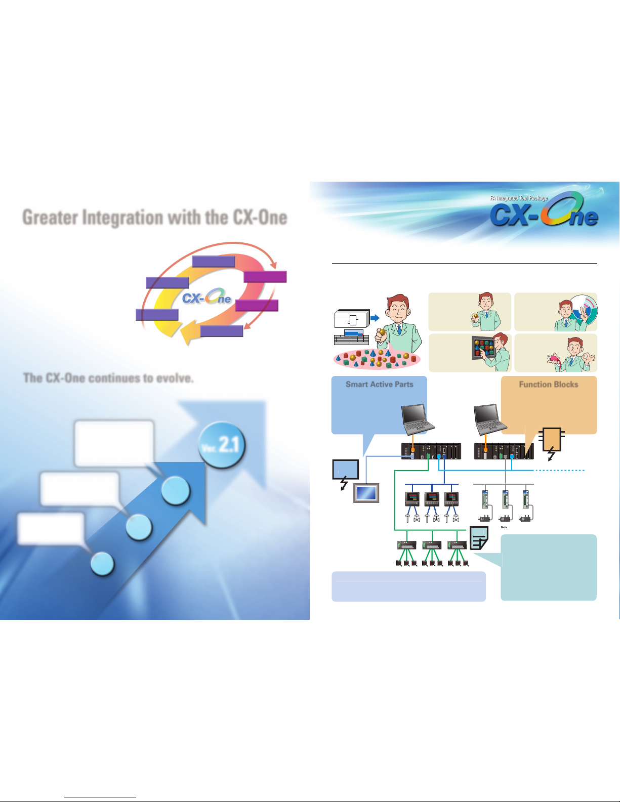
Smart Platform
2 3
Function Block library/Smart Active Parts Library/Component Profile Sheet
(TM)
OMRON's lineup of control devices and controllers includes a wide range or products from Sensors to Temperature
Controllers, Programming Controllers, Motion Controllers, and Touch Panels. And to enable easily connecting, setting
up, and programming these products to quickly achieve the desired FA system, OMRON provides Smart Libraries, a
vital system that supports all of the CX-One Support Software. It's like a dream come true.
Settings can be made
as if a seasoned
worker with vast
experience with
control devices is
right at your side.
Work time and
engineer costs are
greatly reduced.
Communications
programming is built
in, achieving "Plug
and Work"
capabilities.
Just select and
paste to
significantly
improve work
efficiency.
CX-One
Ver. 2. 0
CX-One
Ver. 1.0
Greater Integration with the CX-One
The Smart Libraries support the entire CX-One system.
The CX-One continues to evolve.
: MECHATROLINK is a registered trademark of the MECHATROLIN
K
Members A
ssociatio
n.
With complete integrated simulation
and improved support for sequential
function charts, structured text, and
other IEC 61131-3 languages, CX-One
version 2.1 provides performance for
all stages of production, from
equipment design, programming, and
debugging through startup, operation,
and maintenance to help reduce the
customer's Total Cost of Ownership.
Progressing toward
further development!
E
n
g
i
n
e
e
r
c
o
s
t
s
f
o
r
w
o
r
k
T
i
m
e
r
e
q
u
i
r
e
d
Normal
completion
Temper ature
Controller unit No.
Set temperature
123
Rotation speed
F B
Smart Active Parts
Activ
e
scree
n
FB
DeviceN
et
CompoWay/
F
Controlle
r Lin
k
Ethern
et
MECHATROLINK-I
I
CPS
The latest objects can be obtained at any time from the Web or a CD-ROM.
Function Blocks
Ver. 2.1
Ver.
Ver.
Ver.
2.0
1.1
1.0
CPS
System Design
Unit Configuration
Parameter Settings
Programming
Integrated Debugging
Operation and
Maintenance
Integrated simulation achieves
online checking of ladder
programming and touch panel
controls. Function blocks can be
created from user ladder
programming and IEC 61131-3
structured text (ST) language can be
used in function blocks.
The new CX-Designer HMI Design
Software joins greatly reducing PLC
programming and debugging work
through features such as function
block nesting and instance
monitoring.
The CX-One was introduced
under the concept of OMRON's
Smart Platform device control
system, which enables easy
access to any device from
anywhere.
A new system released by OMRON in July 2004 for
integrated management of data for control devices and
controllers used in production equipment.
Incorporate Smart Active Parts into your
touch panel screens to reduce work for
both designing and debugging screens
while improving quality
through standardization.
The Function Block Library is a library of
functional programming objects for
OMRON's CS/CJ-series PLCs.
Incorporating function blocks into your
PLC programming reduces work for
developing programming while improving
quality through standardization.
A Component Profile Sheet (CPS) holds ID
data, parameter definitions, and Support
Software data, including model numbers
and unit versions of PLCs and
components. Using the definition data
held in the CPS reduces device setup work
with Support Software. Also, introducing
Component Profile Sheets enables
keeping Support Software up to date.
Objects can be obtained from the CD-ROM supplied with the components
or downloaded as desired from libraries on the Web. The objects can
then be saved in individual custom libraries.
(
See note.
)
Page 3

Integrated simulation can now be
started from the CX-Programmer!
4 5
Integrated simulation can be started
from either the CX-Programmer or the
CX-Designer. This enables more easily
performing integrated simulation and
debugging.
Now, system errors can be easily
checked using only a computer!
Operation of monitoring
programming when errors occur can
be verified on a computer.
Saving operations in CSV files when
errors occur simplifies making test
reports.
Now, variable data can be easily
copied from the CX-Designer to
the CX-Programmer.
Variable data can be easily shared.
No work is required to manage data
allocations.
Comments can also be copied.
Integrated Simulation for Greater Design and Deb ugging Efficienc
y
Even Easier Integrated Simulations!
Greatly Improved Design Efficiency!
The CX-One is even easier to use through the addition of functions from CX-One version 2.0,
such as starting simulation from the CX-Programmer and customizing test screens.
A New PLC Error Simulator Enables Easily Checking
Operation of Debugged Programs When System Errors Occur!
The coverage of integrated simulation has been further expanded by enabling generation of PLC system errors on the computer, thus
eliminating the need to use actual equipment. This allows the user, for example, to easily debug programming that handles system errors.
Variable data can be easily shared between
the CX-Programmer and CX-Designer!
The ability to easily copy and paste CX-Designer variable data to the CX-Programmer further improves the efficiency of integrated simulation.
For example, variables that have been changed due to revisions in touch panel screens can be easily updated in the CX-Programmer.
1
2
3
Position OK!
Starting from the CX-Programmer Starting from the CX-Designer
Starting Integrated Simulation
PLC Error Simulator
Sharing Variable Data
Version
Upgrade
Version
Upgrade
Integrated Simulation between PLCs and Touch Panels
1 Start integrated simulation with
the press of a button.
1 Start integrated simulation with
the press of a button.
2 Select the CX-Designer file.
2 Select the CX-Programmer file.
3 Click the Start Button.
3 Click the Start Button.
During simulation, it is
possible to change the
touch panel display
position, pin the screen
display on top, and
specify the size.
Variable names
Addresses
Comments
Variable names
Addresses
Comments
New adjustment functions enable
customizing the debugging environment!
The size of the PT screen can be changed.
The PT screens can be kept displayed in front.
The PT screen position can be saved.
Startup has been
completed!
NEW
NEW!
CX-Programmer Support
Software for PLCs
CX-Designer Screen Designing
Software for NS-series PT
Touch Panels
Integrated simulation could be started
only from the CX-Designer, even though
starting from the CX-Programmer
would sometimes be more convenient.
There was also the need to customize
screen positioning and other factors in
the debugging environment, and to
keep the PT screens displayed in front.
Previously, error-handling programming
was verified by generating errors using
error-generation commands in a
program running on the PLC.
Preparation and execution required too
much time.
Previously, it was possible to copy and
paste from the CX-Programmer to the
CX-Designer, but not in the opposite
direction. It was a lot of trouble to bring
variable data created in the CX-Designer
to the CX-Programmer.
CX-Programmer Support Software
for PLCs
CX-Designer
Screen Designing Software for
NS-series PT Touch Panels
Starting was
not possible.
Starting was
possible.
Page 4

ST
Ladde
r
programmin
g
Variabl
es
6 7
NEW! NEW!
NEW!
NEW!
Note: The PLC connected to the computer must be a CS/CJ-series PLC
with unit version 4.0 or later.
A wider variety of programming languages is being used along with
the greater diversity of PLC applications.
With the CX-Programmer (CX-One), support for sequential function charts (SFC)
improves program readability.
(See note.)
Compare function block (FB) definitions in detail to
easily manage changes.
Program Conversion from C500/C120/C P.
Easily Handle Demands for Equipment Changes!
Seq
uential Function Charts Function Block Comparison
Using structured text (ST) programming in tasks amazingly
simplifies numerical processing. (See note.)
Structured Text
Enhanced program comparison enables detailed comparison of function blocks and structured text!
Easily Replace Your PLCs with CP1L/H, CJ1, or CS1 PLCs
Sequential function charts (SFC) is a language used to express the flow of process steps as graphical charts that combine steps and transitions. SFC complies with the IEC 61131-3 standard.
Structured text (ST) is a high-level language for industrial control that allows programming numerical processing and repetition processing more simply than ladder diagrams. ST complies with the IEC 61131-1 standard.
Support for sequential function charts and structured text provides for a variety of
rogramming language environments
.
Supported
for unit version
4.0 or later.
Support is provided with CS/CJ-series PLCs with unit
version 4.0 or later.
To acquire a CS/CJ-series PLC with unit version 4.0,
contact your OMRON representative.
It takes
almost 30
minutes to
program using
ladder
diagrams!
Program averaging
of 200 points in
only nine lines.
Written in five
minutes!
Present values can
be monitored and
changed.
(All work times are reference values.)
F
BFB
FB_MC1_P
1B_
MC1_P
1
The flow of process step programming
is difficult to understand with ladder
programming. Plus, interlocks and
jumps are required.
Until now, it has not been possible to
see the results of detailed comparison
of ladder programming in function
block (FB) definitions. This made it
difficult to manage changes in function
blocks.
Using ladder programming to write
numerical processing is complicated. The
number of inputs increases and it takes a
lot of time to write averages or values for
hundreds of measurement values.
Using SFC enables understanding
the line structure and the process
flow at a glance!
Programming can be made that follows
the process flow.
The processes that are being executed
can be understood at a glance, which
simplifies monitoring process status.
Programming each process separately
helps to achieve structured programs
and makes programming easier to reuse.
Detailed comparison of function
block definitions can be
p
erformed
from CX-Pro
g
rammer version 7.2.
Ladder programming, ST, and
changes in variables in FB definitions
can be checked in detail.
Temporarily backing up C500/C120/C P-series programs
to a computer, such as is required when replacing Units,
was possible only when the PLC was online with the
computer. Working online was not possible when
converted to other models.
With C500/C120/C P-series PLCs, only the programs
could be backed up, but not data from the DM or HR
Areas.
Files backed up on a computer from C500/C120/C P-series
PLCs can be converted to projects for the CP1L/M, CJ1, CS1,
or CVM1. Of course, work can be performed online.
With C500/C120/C P-series PLCs, only the programs could
be backed up, but the backup function has been expanded to
now include programs, DM Area data, and HR Area data.
CX-One version 2.1 can be used to change models to the
CP1L, which is ideal for updating small machinery and
equipment.
Using ST, writing a program to
average hundreds of points
requires only a few lines!
The ability to write repetition processing
and judgment processing in only a few
lines greatly shortens the time required
for programming.
Text string data is can be used. Measured
thickness data or other text string data
can be easily analyzed.
Designed
June 12
esigned
June 15
Note: The PLC connected to the computer must be
a CS/CJ-series PLC with unit version 4.0 or later.
Supported
for unit version
4.0 or later.
Support is provided with CS/CJ-series
PLCs with unit version 4.0 or later.
To acquire a CS/CJ-series PLC with
unit version 4.0, contact your OMRON
representative.
There seem to
be some
changes, but
what was
changed?
Page 5

Failur
eTransfer
Time
R
etransfe
r
ompleted
Transfer time onsi
te
8 9
Transfer to computer from a DeviceNet network can
be resumed!
The maximum number of Controller Link data link send
words per node has been increased from 1,000 to 4,000!
Easier Adjustment for Temperature and
Process Control!
If communications fail when uploading DeviceNet network data (slave
data) using the CX-Integrator, uploading can be resumed from the point
where failure occurred, thereby greatly shortening the time for
transferring network data to the computer.
Support is provided for Controller Link Units (soon to be released), which
have increased the maximum number of send/receive words per Unit
fourfold from the previous 1,000 words to 4,000 words when data links
are used (see note). This can be used to increase the amount of data
shared between PLCs, such as for exchanging data on quality.
Note: CS1W-CLK13/23/53, CJ1W-CLK23, and 3G8F7-CLK13/23/53.
Version 3.2 of the CX-Thermo
Now, settings of parameters being
monitored in the Trend View Window can be
changed.
Easier Memory Allocation for the EJ1 and PLCs
Now, parameter selections and memory
allocations for programless communications
of the EJ1 and PLCs can be set in a table
while viewing the PLC memory address.
Ethern
et
Routing tables can be transferred from one location to
multiple PLCs!
Routing tables can be set and transferred from one PLC to other PLCs on a network without reconnecting cables. (See note.)
Transferring routing tables is easy using a direct
Ethernet connection!
Routing tables can be transferred from a computer to a PLC connected with an Ethernet cable.
Transferring Routing Tables to Networks
Direct Ethernet Connections
Version
Upgrade
The Popular Automatic Online Connection to PLCs Is Now Even Easier!
The computer's serial ports are automatically searched when an automatic online connection is used,
so it is no longer necessary to individually specify the port used.
Automatic Search for Computer Port for Automatic Online Connection
Version
Upgrade
Version
Upgrade
Version
Upgrade
Setting and transferring routing tables
required a lot of time onsite to
reconnect the cables for each PLC.
Routing tables can be set and
transferred from a PLC in just one
location!
Work is greatly simplified by the ability
to set and transfer routing tables from
one location to all the PLCs on a
network of the same layer.
The computer port (e.g., COM2 or COM3)
had to be specified using a separate menu
command for selecting the connection port
when an automatic online connection was
performed with the PLC connected to the
computer's USB port (except for COM1).
No communications port settings are
required! Only the connectable
communications ports are displayed,
so online connection is easy.
Online connection can be easily made with
two clicks of the mouse. There's no need to
worry whether online connection at the
worksite will be possible when an error occurs.
Routing tables can be transferred
with the PLCs connected to an
Ethernet network.
Routing tables can be transferred from
the computer to a PLC using an
Ethernet cable. No work is required for
reconnecting Peripheral Cables onsite.
A separate Peripheral Cable was
required to transfer routing tables when
the computer and the PLC were directly
connected using Ethernet. Work for
making routing table settings onsite
was troublesome.
Network
Serial
connection
Note: Routing tables cannot be set across network layers (same as
previously).
The PLC connected to the computer must be a CS/CJ-series PLC
with unit version 4.0 or later.
Supported
for unit version
4.0 or later.
Support is provided with CS/CJ-series PLCs with unit
version 4.0 or later.
To acquire a CS/CJ-series PLC with unit version 4.0,
contact your OMRON representative.
Work is
easy!
Easy online
connection
with two
clicks!
No Peripheral Cable
required!
of the port used on
the computer
Much shorter!
Even Less Time Required to Design Network
s
Resuming transfer
to computer No
Start
Resuming transfer
to computer Yes
Page 6

Make numeral displays and input objects more attractive, and increase or decrease the character string font size as desired.
There is no need to create similar error screens, so you can easily create a device troubleshooter.
Troubleshooting Easily Supported with Multi-language Functionality
Greatly Enhanced Libraries of Beautiful
Lamps and Switches
10 11
Use an attractive font for numerals that looks good on the display even when it is enlarged. Seven-segment fonts are also available. And,
smooth fonts can be used for alarms and character strings, and scalable fonts can be selected. In addition, worldwide support is provided
with 42 languages, including Thai.
New 7-segment font
Thai
Alarm display with new scalable Gothic font
New numeral font
A selection of over 800 beautiful objects is
provided. Now, it's easier to allocate and change
objects.
Individual error display screens that were previously created for
each error can now be integrated into one. It is possible to switch
only the error details (text and
screen) without ladder
programming in conjunction with
the alarm bit
Multi-language machine troubleshooting can be easily achieved by saving the English
screen data in an Excel file, having it translated, and then importing the results.
CX-One version 2.1 newly supports Windows Vista, the latest
edition of the Microsoft OS.
CX-One can now be used on the latest computer OS. Version 2.1
also support Korean Windows. Transitioning and training onsite
will be easier in any application environment, even with the
expected expansion of tasks abroad. With CX-One version 2.1,
Korean display is possible for tool menus and comments in the
CX-Programmer, as well as for the installation windows.
With this system,
the frames are
shared, and the
error details in the
pink frames are
switched with an
alarm or other item
as the trigger.
Text selection Screen selection
Support for the Latest Windows OS Vista
Further Expansion of Applications Environments with
Support for Korean
Ver. 2. 1
Upgrade planned for the near future
Greater Beauty
Easier Design of Device Error Screens
Greater Beauty, Simpler,
and Better Multi-language Support
For example, in conjunction with an alarm bit (See note.)
Alarm bit 10.01 ON (no paper)
Alarm bit 10.02 ON (printing error)
Note: Alarms, PLC/PT memory, and other items can be
selected for the switching trigger.
The following table shows the Support Software (Configuration Tools) installed by the CX-One Version 2.1
.
FA Integrated Too
l
Package CX-On
e
Version 2.
1
FA Integrated Tool
Package CX-One
Lite Version 2.
1
Nam
e
Compatible O
S
Descriptio
n
Media
See note 2.
)
M
odel
Number of licenses
See note 1.
)
Compute
r
Memory (See notes 2.
)
Hard di
sk
Displa
y
Disk driv
e
Communications port
s
h
er
IBM PC/AT or compatible
with a processor
recommended by Microsoft.
CX-Programme
r
Ver. 7.
2
(Upgrade planned
CX-Integrato
r
Ver. 2.
1
X-Pr
otocolVe
r. 1.
7
X-Simul
atorVe
r. 1.
8
X-Positi
onVe
r. 2.
4
X-Motion-N
CF
Ver. 1.
5
Operating system (OS)
See notes 1.
)
Microsoft Windows98 SE
Microsoft Windows NT
(Service Pack 6a)
Microsoft Windows Vista
(except 64-bit edition)
(See note 4.)
Micr
osoft
Windows 2
000
(Service Pack 3 or higher) or
Mi
crosoft
Windows M
e
Micr
osoft
Windows X
P
512 MB minimum,
1 GB recommended.
I
tem
lin
e
Support Software
in CX-On
e
lin
e
Support Software
in CX-On
e
Requiremen
t
Approx. 2.2 GB or more available space is required to install the complete CX-One package.
SVGA (800 x 600) or better high-resolution display with 256 colors min. XGA or better display is required for the CX-Process Software.
CD-ROM drive or DVD drive
One RS-232C port min. (See note 3.)
Internet access is required to use online user registration, including a modem or other hardware connection method.
256 MB minimum, 512 MB recommended.
IBM PC/AT or com
p
atible with a Pentium II 333 MHz or faster processor (Pentium III 1 GHz or faster recommended.
)
SwitchBox Utilit
y
Ver. 1.
6
X-Moti
onVe
r. 2.
3
CX-Drive
Ver. 1.
4
X-Pr
ocess Too
l
Ver. 5.
1
Faceplate Auto
-
Builder for NS
Ver. 3.
0
X-Thermo Ver. 3.2
See note 3.
)
X-FLn
etVe
r. 1.
0
CX-Motion-MC
H
Ver. 2.
1
XONE-AL50D-EV
2
XONE-LT01C-EV
2
XONE-AL
50C
-EV
2
CXONE-AL30D-EV
2
XONE-AL
30C
-EV
2
XONE-AL10D-EV
2
XONE-AL10C-EV
2
XONE-AL03D-EV
2
XONE-AL
03C
-EV
2
XONE-AL01D-EV
2
XONE-AL01C-EV
2
1 licen
se
3 license
s
10 licen
ses
licen
ses
licen
ses
1 licen
se
D
C
D
Ordering Informatio
n
System Requirement
s
Support Software Contained in the CX-One Version 2.
1
Windows 98 SE, Me, NT 4.0
(Service Pack 6a)
,
2000
(Service Pack 3 or hi
g
her), XP,
r Vi
sta
N
ote
supported
.
downloaded and updated
from the Micr
osoft
Downl
oad center of eac
h
region
.
CX-One is a comprehensive software package
t
hat integrates Support Software for OMRON
PLCs and com
p
onents
.
CX-One Lite is a subset (see note 3) of the complete
CX-One packa
g
e that provides only the Support
Software re
q
uired for micro PLC applications. It can
be used onl
y
with micro PLCs. (See note 4.)
N
ote
1: Site licenses are available for users who will run CX-One on multiple computers. Ask your OMRON sales representative for details.
N
ote
2: When purchasing the DVD format, verify the computer model and DVD drive specifications before purchasing.
N
ote
3: CX-One Lite provides the following Support Software: CX-Programmer Ver. 7.2 (micro PLCs only), CX-Integrator Ver. 2.1, CX-Simulator Ver. 1.8, CX-Designer Ver. 2.1, CX-Protocol Ver. 1.7,
N
ote
4: The following micro PLCs are supported by CX-One Lite: CP1@, CPM@@, and SRM1.
N
ote
If the complete CX-One package is installed, approximately 1.9 GB of hard disk space will be
required.
3: Installation and operation are supported only for Microsoft Windows 2000 (Service Pack 3 or
higher) and XP.
CX-One OS Precaution: The CX-One will not run on Microsoft Windows 95 or any other OS not
listed above. If such an OS is being used on the client computer, the OS must be upgraded before
installing the CX-One. System requirements and hard disk space may vary with the system
environment.
The amount of memory required varies with the Support Software applications used in CX-One.
Refer to user documentation for individual Support Software for details.
N
ote
Note 2:
An RS-232C port is required to connect the Support Software applications in CX-One to a PLC. If
the computer provides only a USB port, use a CS1W-CIF31 USB/RS-232C Conversion Cable. To
connect to a CP-series/NSJ-series PLC, however, an over-the-counter USB cable (type A-B) can be
used to connected to the built-in USB port on the CP-series/NSJ-series PLC.
The following restriction apply when using CX-One version 2.1 with Windows Vista.
• Some help files require downloading tool software provided by Microsoft. When connected to
the Internet, a page for downloading will be displayed if a help file that requires support software
is opened. (http://support.microsoft.com/kb/917607/en)
Restrictions apply to operation of some applications. Refer to the Setup Manual for details
.
Note 3:
Note 4:
Application software to create and debug programs for SYSMAC
CS/CJ/CP/NSJ-series
,
C-series, and CVM1/CV-series CPU Units
.
Application software to simulate SYSMAC CS/CJ/CP/NSJ-series
CPU Unit operation on the computer to debu
g
PLC programs
wi
thout a CPU Unit.
Application software to create and monitor data for SYSMAC
CS
/
CJ-series Position Control Units
.
Application software to monitor and set parameters for SYSMAC
CS/CJ-series Position Control Units that su
pp
ort MECHATROLINK-II
communications.
(
See note 2.
)
Application software to create protocols (communications sequences)
between SYSMAC CS
/CJ/CP/
NSJ-series or C200HX/HG/HE Serial
Communications Boards/Units/ Option Boards and
g
eneral-purpose
xternal devi
ces.
Application software to create data and motion programming and
perform monitorin
g
for SYSMAC CS/CJ-series MCH Units that
su
pp
ort MECHATROLINK-II communications. (See note 2.
)
Application software to create data for SYSMAC CS-series,
C200HX/HG/HE
,
and CVM1/Cvseries Motion Control Units, and to
create and monitor motion control pro
g
rams.
Application software to create and debu
g
function block programs
for SYSMAC CS/CJ-series Loo
p
Controllers (Loop Control
Units/Boards, Process Control CPU Units, and Loo
p
Control CPU
A
pp
lication software that automatically outputs screen data as
project files for NS-series PTs from ta
g
information in function
block pro
g
rams created with the CX-Process Tool
.
Application software to set and control parameters in components,
such as Tem
p
erature Control Units
.
Application software for system setting and monitoring of SYSMAC
CS
/
CJ-series FL-net Units
.
Utility software that helps debug PLCs. It helps to monitor the I/O
status and to monitor/chan
g
e specified present values within a PLC.
X-Profi
bus
Ver. 1.
1
Software to configure a PROFIBUS Master
.
Application software to set and control data for Inverters and
A
pp
lication software to create screen data for the NS-series PT
T
ouc
h Panel
s.
Application software to build and set up FA networks, such as
Controller Link, DeviceNet, CompoWay/F, and Ethernet. The Routin
g
Table Component and Data Link Component can be started from this
software. DeviceNet Confi
g
uration functionality is also included
.
 Loading...