

Page 1

Cat. No. W448-E1-05
SYSMAC
CXONE-AL_C-V4/
CXONE-AL_D-V4
CX-Motion-MCH
OPERATION MANUAL
Page 2

Page 3

CXONE-AL@@C-V4/
CXONE-AL@@D-V4
CX-Motion-MCH
Operation Manual
Revised December 2009
Page 4

iv
Page 5

Notice:
r
f
OMRON products are manufactured for use according to proper procedures by a qualified operator
and only for the purposes described in this manual.
The following conventions are used to indicate and classify precautions in this manual. Always heed
the information provided with them. Failure to heed precautions can result in injury to people or damage to property.
!DANGER Indicates an imminently hazardous situation which, if not avoided, will result in death or
serious injury. Additionally, there may be severe property damage.
!WARNING Indicates a potentially hazardous situation which, if not avoided, could result in death or
serious injury. Additionally, there may be severe property damage.
!Caution Indicates a potentially hazardous situation which, if not avoided, may result in minor or
moderate injury, or property damage.
OMRON Product References
All OMRON products are capitalized in this manual. The word “Unit” is also capitalized when it refers to
an OMRON product, regardless of whether or not it appears in the proper name of the product.
The abbreviation “Ch,” which appears in some displays and on some OMRON products, often means
“word” and is abbreviated “Wd” in documentation in this sense.
The abbreviation “PLC” means Programmable Controller. “PC” is used, however, in some Programming Device displays to mean Programmable Controller.
Visual Aids
The following headings appear in the left column of the manual to help you locate different types of
information.
OMRON, 2005
All rights reserved. No part of this publication may be reproduced, stored in a retrieval system, or transmitted, in any form, o
by any means, mechanical, electronic, photocopying, recording, or otherwise, without the prior written permission o
OMRON.
No patent liability is assumed with respect to the use of the information contained herein. Moreover, because OMRON is constantly striving to improve its high-quality products, the information contained in this manual is subject to change without
notice. Every precaution has been taken in the preparation of this manual. Nevertheless, OMRON assumes no responsibility
for errors or omissions. Neither is any liability assumed for damages resulting from the use of the information contained in
this publication.
Note Indicates information of particular interest for efficient and convenient opera-
tion of the product.
1,2,3... 1. Indicates lists of one sort or another, such as procedures, checklists, etc.
v
Page 6

vi
Page 7

TABLE OF CONTENTS
PRECAUTIONS . . . . . . . . . . . . . . . . . . . . . . . . . . . . . . . . . . . xvii
1 Intended Audience. . . . . . . . . . . . . . . . . . . . . . . . . . . . . . . . . . . . . . . . . . . . . . . . . . . . . . . . . xviii
2 General Precautions . . . . . . . . . . . . . . . . . . . . . . . . . . . . . . . . . . . . . . . . . . . . . . . . . . . . . . . . xviii
3 Safety Precautions . . . . . . . . . . . . . . . . . . . . . . . . . . . . . . . . . . . . . . . . . . . . . . . . . . . . . . . . . xviii
4 Operating Environment Precautions . . . . . . . . . . . . . . . . . . . . . . . . . . . . . . . . . . . . . . . . . . . xix
5 Application Precautions. . . . . . . . . . . . . . . . . . . . . . . . . . . . . . . . . . . . . . . . . . . . . . . . . . . . .xix
SECTION 1
Overview of the CX-Motion MCH . . . . . . . . . . . . . . . . . . . . 1
1-1 What is the CX-Motion-MCH? . . . . . . . . . . . . . . . . . . . . . . . . . . . . . . . . . . . . . . . . . . . . . . . 2
1-2 System Configuration . . . . . . . . . . . . . . . . . . . . . . . . . . . . . . . . . . . . . . . . . . . . . . . . . . . . . . 3
1-3 Function List . . . . . . . . . . . . . . . . . . . . . . . . . . . . . . . . . . . . . . . . . . . . . . . . . . . . . . . . . . . . . 4
1-4 Operation Procedure . . . . . . . . . . . . . . . . . . . . . . . . . . . . . . . . . . . . . . . . . . . . . . . . . . . . . . . 6
SECTION 2
Setup. . . . . . . . . . . . . . . . . . . . . . . . . . . . . . . . . . . . . . . . . . . . . 7
2-1 Installing and Uninstalling the Software . . . . . . . . . . . . . . . . . . . . . . . . . . . . . . . . . . . . . . . . 8
2-2 Connecting to a PLC . . . . . . . . . . . . . . . . . . . . . . . . . . . . . . . . . . . . . . . . . . . . . . . . . . . . . . . 8
SECTION 3
Basic Operations . . . . . . . . . . . . . . . . . . . . . . . . . . . . . . . . . . . 13
3-1 Basic Operations . . . . . . . . . . . . . . . . . . . . . . . . . . . . . . . . . . . . . . . . . . . . . . . . . . . . . . . . . . 14
3-2 Operations Listed by Purpose . . . . . . . . . . . . . . . . . . . . . . . . . . . . . . . . . . . . . . . . . . . . . . . . 25
SECTION 4
Creating Projects . . . . . . . . . . . . . . . . . . . . . . . . . . . . . . . . . . 29
4-1 Creating a New Project . . . . . . . . . . . . . . . . . . . . . . . . . . . . . . . . . . . . . . . . . . . . . . . . . . . . . 30
4-2 Adding and Deleting MC Units. . . . . . . . . . . . . . . . . . . . . . . . . . . . . . . . . . . . . . . . . . . . . . . 31
4-3 Adding and Deleting Tasks . . . . . . . . . . . . . . . . . . . . . . . . . . . . . . . . . . . . . . . . . . . . . . . . . .32
4-4 Adding and Deleting Axes. . . . . . . . . . . . . . . . . . . . . . . . . . . . . . . . . . . . . . . . . . . . . . . . . . .33
4-5 Adding and Deleting Programs . . . . . . . . . . . . . . . . . . . . . . . . . . . . . . . . . . . . . . . . . . . . . . . 34
4-6 Adding and Deleting Subprograms . . . . . . . . . . . . . . . . . . . . . . . . . . . . . . . . . . . . . . . . . . . . 35
4-7 Adding and Deleting CAMs . . . . . . . . . . . . . . . . . . . . . . . . . . . . . . . . . . . . . . . . . . . . . . . . . 37
SECTION 5
Editing Data. . . . . . . . . . . . . . . . . . . . . . . . . . . . . . . . . . . . . . . 39
5-1 Editing Data . . . . . . . . . . . . . . . . . . . . . . . . . . . . . . . . . . . . . . . . . . . . . . . . . . . . . . . . . . . . . . 40
vii
Page 8

TABLE OF CONTENTS
SECTION 6
Saving and Reading Projects . . . . . . . . . . . . . . . . . . . . . . . . . 43
6-1 Saving a Project . . . . . . . . . . . . . . . . . . . . . . . . . . . . . . . . . . . . . . . . . . . . . . . . . . . . . . . . . . . 44
6-2 Reading a Project. . . . . . . . . . . . . . . . . . . . . . . . . . . . . . . . . . . . . . . . . . . . . . . . . . . . . . . . . . 44
6-3 Importing Files . . . . . . . . . . . . . . . . . . . . . . . . . . . . . . . . . . . . . . . . . . . . . . . . . . . . . . . . . . . 45
6-4 Exporting File . . . . . . . . . . . . . . . . . . . . . . . . . . . . . . . . . . . . . . . . . . . . . . . . . . . . . . . . . . . . 48
SECTION 7
Transferring and Comparing Data . . . . . . . . . . . . . . . . . . . . 53
7-1 Initial Settings for Online Connection. . . . . . . . . . . . . . . . . . . . . . . . . . . . . . . . . . . . . . . . . . 54
7-2 Setting/Changing Communications Specifications . . . . . . . . . . . . . . . . . . . . . . . . . . . . . . . . 54
7-3 Transferring, Comparing, and Saving Data. . . . . . . . . . . . . . . . . . . . . . . . . . . . . . . . . . . . . . 56
SECTION 8
Monitoring. . . . . . . . . . . . . . . . . . . . . . . . . . . . . . . . . . . . . . . . 63
8-1 Status Monitor . . . . . . . . . . . . . . . . . . . . . . . . . . . . . . . . . . . . . . . . . . . . . . . . . . . . . . . . . . . . 64
8-2 General Watch Window. . . . . . . . . . . . . . . . . . . . . . . . . . . . . . . . . . . . . . . . . . . . . . . . . . . . .64
SECTION 9
Operation . . . . . . . . . . . . . . . . . . . . . . . . . . . . . . . . . . . . . . . . . 65
9-1 Switching to Monitor Mode . . . . . . . . . . . . . . . . . . . . . . . . . . . . . . . . . . . . . . . . . . . . . . . . . 66
9-2 Test Run . . . . . . . . . . . . . . . . . . . . . . . . . . . . . . . . . . . . . . . . . . . . . . . . . . . . . . . . . . . . . . . . . 67
9-3 Debugging the Program. . . . . . . . . . . . . . . . . . . . . . . . . . . . . . . . . . . . . . . . . . . . . . . . . . . . .69
SECTION 10
Data Traces . . . . . . . . . . . . . . . . . . . . . . . . . . . . . . . . . . . . . . . 73
10-1 Data Traces . . . . . . . . . . . . . . . . . . . . . . . . . . . . . . . . . . . . . . . . . . . . . . . . . . . . . . . . . . . . . . 74
SECTION 11
Backup and Restore . . . . . . . . . . . . . . . . . . . . . . . . . . . . . . . . 77
11-1 Backup from MC . . . . . . . . . . . . . . . . . . . . . . . . . . . . . . . . . . . . . . . . . . . . . . . . . . . . . . . . . . 78
11-2 Restoring to MC . . . . . . . . . . . . . . . . . . . . . . . . . . . . . . . . . . . . . . . . . . . . . . . . . . . . . . . . . . 78
11-3 Verifying Backup File with MC Unit . . . . . . . . . . . . . . . . . . . . . . . . . . . . . . . . . . . . . . . . . . 79
SECTION 12
Read Protection. . . . . . . . . . . . . . . . . . . . . . . . . . . . . . . . . . . . 81
12-1 Read Protection . . . . . . . . . . . . . . . . . . . . . . . . . . . . . . . . . . . . . . . . . . . . . . . . . . . . . . . . . . . 82
12-2 Setting and Changing Passwords. . . . . . . . . . . . . . . . . . . . . . . . . . . . . . . . . . . . . . . . . . . . . . 83
12-3 Setting and Releasing Protection . . . . . . . . . . . . . . . . . . . . . . . . . . . . . . . . . . . . . . . . . . . . . . 85
12-4 Switching the User. . . . . . . . . . . . . . . . . . . . . . . . . . . . . . . . . . . . . . . . . . . . . . . . . . . . . . . . . 86
viii
Page 9

TABLE OF CONTENTS
SECTION 13
Printing . . . . . . . . . . . . . . . . . . . . . . . . . . . . . . . . . . . . . . . . . . 87
13-1 Printing . . . . . . . . . . . . . . . . . . . . . . . . . . . . . . . . . . . . . . . . . . . . . . . . . . . . . . . . . . . . . . . . . 88
SECTION 14
Error Log. . . . . . . . . . . . . . . . . . . . . . . . . . . . . . . . . . . . . . . . . 91
14-1 Error Log . . . . . . . . . . . . . . . . . . . . . . . . . . . . . . . . . . . . . . . . . . . . . . . . . . . . . . . . . . . . . . . . 92
14-2 Error Codes . . . . . . . . . . . . . . . . . . . . . . . . . . . . . . . . . . . . . . . . . . . . . . . . . . . . . . . . . . . . . . 92
SECTION 15
Troubleshooting . . . . . . . . . . . . . . . . . . . . . . . . . . . . . . . . . . . 93
15-1 Troubleshooting. . . . . . . . . . . . . . . . . . . . . . . . . . . . . . . . . . . . . . . . . . . . . . . . . . . . . . . . . . . 94
15-2 Error Codes . . . . . . . . . . . . . . . . . . . . . . . . . . . . . . . . . . . . . . . . . . . . . . . . . . . . . . . . . . . . . . 101
Revision History . . . . . . . . . . . . . . . . . . . . . . . . . . . . . . . . . . . 115
ix
Page 10

TABLE OF CONTENTS
x
Page 11

About this Manual:
This manual provides information required to use the CX-Motion-MCH software, including specifications and operating methods. The CX-Motion-MCH runs on Windows 2000, XP, Vista, or 7 and is used
to set data used by CS1W-MCH71 and CJ1W-MCH71 Motion Control Units (also referred to as MC
Units), create the required programs, and monitor the MC Unit’s operating status.
Please read this manual carefully and be sure you understand the information provided before
attempting to use the CX-Motion-MCH. Be sure to read the precautions provided in the following section.
Please read the MC Unit Operation Manual carefully and be sure you understand the information provided before setting up or using an application for a Motion Control Unit.
Name Contents Cat. No.
SYSMAC CX-Motion-MCH
Operation Manual
SYSMAC CS1W/CJ1WMCH71
Motion Control Unit
Operation Manual
For details on procedures for installing the CX-Motion-MCH from the CX-One FA Integrated Tool Package, refer to the CX-One Setup Manual provided with CX-One.
Cat. No. Model Name Contents
W463 CXONE-AL@@C-
V4/AL@@D-V4
Describes the specifications and operating procedures for
the CX-Motion-MCH.
Describes the installation and operation of the CS1W/
CJ1W-MCH71 Motion Control Unit.
CX-One Setup Manual Installation and overview of CX-One FA
Integrated Tool Package.
(suffixes omitted)
W448 (this manual)
W435
xi
Page 12

Precautions provides general precautions for using the CX-Motion-MCH, Programmable Controller,
and related devices.
Section 1 provides an overview of the CX-Motion-MCH, and describes the functions and system configuration required to operate the CX-Motion-MCH. Be sure to read this section before using the CXMotion MCH.
Section 2 provides information on installing the CX-Motion-MCH and CX-Server, and connecting to
the PLC.
Section 3 describes each of the windows and basic operations.
Section 4 provides information on creating projects and adding MC Units, tasks, axes, programs, sub-
programs, and CAM tables.
Section 5 describes the operations used to edit data.
Section 6 describes the operations used to save and read new projects.
Section 7 describes the operations used to transfer or compare data between the personal computer
and Motion Control Unit/Servo Driver, and to write data transferred to the Motion Control Unit to the
Motion Control Unit's flash memory.
Section 8 provides information on monitoring the MC Units. The MC Unit's communications status,
error status, and axis's present position and status are displayed in the Monitor Windows.
Section 9 describes various operations on the axes of the MC Unit, including test run operations and
program debugging.
Section 10 describes the data trace function.
Section 11 describes the operations used to back up data from MC Units and restore data to MC
Units.
Section 12 describes the operations used to set and release protection on programs or cam data in
MC Units, set and change primary and secondary passwords, and switch the user.
Section 13 describes the operations used to print project data.
Section 14 provides information on the error log generated by the MC Unit.
Section 15 provides information on the troubleshooting methods for the MC Unit.
xii
Page 13

Read and Understand this Manual
Please read and understand this manual before using the product. Please consult your OMRON
representative if you have any questions or comments.
Warranty and Limitations of Liability
WARRANTY
(1) The warranty period for the Software is one year from either the date of purchase or the date on which
the Software is delivered to the specified location.
(2) If the User discovers a defect in the Software (i.e., substantial non-conformity with the manual), and
returns it to OMRON within the above warranty period, OMRON will replace the Software without charge
by offering media or downloading services from the Internet. And if the User discovers a defect in the
media which is attributable to OMRON and returns the Software to OMRON within the above warranty
period, OMRON will replace the defective media without charge. If OMRON is unable to replace the
defective media or correct the Software, the liability of OMRON and the User's remedy shall be limited to
a refund of the license fee paid to OMRON for the Software.
LIMITATIONS OF LIABILITY
(1) THE ABOVE WARRANTY SHALL CONSTITUTE THE USER'S SOLE AND EXCLUSIVE REMEDIES
AGAINST OMRON AND THERE ARE NO OTHER WARRANTIES, EXPRESSED OR IMPLIED,
INCLUDING BUT NOT LIMITED TO, WARRANTY OF MERCHANTABILITY OR FITNESS FOR A
PARTICULAR PURPOSE. IN NO EVENT WILL OMRON BE LIABLE FOR ANY LOST PROFITS OR
OTHER INDIRECT, INCIDENTAL, SPECIAL, OR CONSEQUENTIAL DAMAGES ARISING OUT OF
USE OF THE SOFTWARE.
(2) OMRON SHALL ASSUME NO LIABILITY FOR DEFECTS IN THE SOFTWARE BASED ON
MODIFICATION OR ALTERATION OF THE SOFTWARE BY THE USER OR ANY THIRD PARTY.
(3) OMRON SHALL ASSUME NO LIABILITY FOR SOFTWARE DEVELOPED BY THE USER OR ANY
THIRD PARTY BASED ON THE SOFTWARE OR ANY CONSEQUENCE THEREOF.
Application Considerations
SUITABILITY FOR USE
THE USER SHALL NOT USE THE SOFTWARE FOR A PURPOSE THAT IS NOT DESCRIBED IN THE
ATTACHED USER MANUAL.
xiii
Page 14

Disclaimers
CHANGE IN SPECIFICATIONS
The software specifications and accessories may be changed at any time based on improvements or for
other reasons.
EXTENT OF SERVICE
The license fee of the Software does not include service costs, such as dispatching technical staff.
ERRORS AND OMISSIONS
The information in this manual has been carefully checked and is believed to be accurate; however, no
responsibility is assumed for clerical, typographical, or proofreading errors, or omissions.
xiv
Page 15

Version Upgrade Information
Improvements from Version 2.2 to Version 2.24
New functions are listed in the following table.
Ver. 2.2 Ver. 2.24
Applicable OS: Windows 2000,
XP, or Vista
Improvements from Version 2.1 to Version 2.2
New functions are listed in the following table.
Ver. 2.1 Ver. 2.2
Motion Control Units in CS/CJseries PLCs (excluding CJ2
PLCs) were supported.
Version Upgrade from Version 2.0 to Version 2.1
New functions are listed in the following table.
Ver. 2.0 Ver. 2.1
The CX-Motion-MCH could not
backup data from MC Units,
restore data to MC Units and verify backup files with MC Units.
The CX-Motion-MCH could not
provide read protection.
The CX-Motion-MCH could not
search in programs.
The CX-Motion-MCH could compare data with MC Units in detail.
Applicable OS: Windows 2000, XP, Vista, or 7
Motion Control Units in CS/CJ-series PLCs
(including CJ2 PLCs) are supported.
The CX-Motion-MCH can execute Backup from
MC Units, Restore to MC Units and Verify
backup files with MC Units.
The CX-Motion-MCH can set/release Read Protection.
The CX-Motion-MCH can set passwords and
switch user status.
The CX-Motion-MCH can find words in all programs.
The CX-Motion-MCH can compare data with MC
Units in detail.
The CX-Motion-MCH can display comparison
results in Overview/Detail View.
The CX-Motion-MCH can save results of comparing programs.
Note All new functions can be used with Motion Control Units with unit version 3.1
or later.
Version Upgrade from Version 1.0 to Version 2.0
New functions are listed in the following table.
Ver. 1.0 Ver. 2.0
The CX-Motion-MCH could not
execute data traces.
The CX-Motion-MCH could not
execute test runs.
The CX-Motion-MCH can execute data traces.
The results of a trace are displayed graphically.
The CX-Motion-MCH can execute the test run
operations, such as the following: Servo locks,
JOG operations, STEP operations, origin
searches, origin returns, forced origins, setting
an absolute origin, teaching, and resetting
errors.
xv
Page 16

Ver. 1.0 Ver. 2.0
The CX-Motion-MCH could not
execute motion programs.
The CX-Motion-MCH could be
used to set only the previous
parameters.
The CX-Motion-MCH can execute motion programs. Motion programs can be debugged by
setting break points and by using single step
execution.
New parameters have been added to use the following functions.
• Zones
• A setting for the number of the parallel
branches in each motion task
• Establishing the origin using the present position preset
• Changing the motor to Servo OFF state using
an external input signal.
Note All new functions can be used in Motion Control Units with unit version 3.0 or
later.
xvi
Page 17

PRECAUTIONS
This section provides general precautions for using the CX-Motion-MCH software package.
The information contained in this section is important for the safe and reliable application of the CX-Motion-MCH.
You must read this section and understand the information contained before attempting to set up or operate the CXMotion-MCH.
1 Intended Audience . . . . . . . . . . . . . . . . . . . . . . . . . . . . . . . . . . . . . . . . . . . . . xviii
2 General Precautions . . . . . . . . . . . . . . . . . . . . . . . . . . . . . . . . . . . . . . . . . . . . xviii
3 Safety Precautions. . . . . . . . . . . . . . . . . . . . . . . . . . . . . . . . . . . . . . . . . . . . . . xviii
4 Operating Environment Precautions . . . . . . . . . . . . . . . . . . . . . . . . . . . . . . . . xix
5 Application Precautions . . . . . . . . . . . . . . . . . . . . . . . . . . . . . . . . . . . . . . . . . xix
xvii
Page 18

Intended Audience 1
1 Intended Audience
This manual is intended for the following personnel, who must also have
knowledge of electrical systems (an electrical engineer or the equivalent).
• Personnel in charge of installing FA systems.
• Personnel in charge of designing FA systems.
• Personnel in charge of managing FA systems and facilities.
2 General Precautions
The user must operate the product according to the performance specifications described in the operation manuals.
Before using the product under conditions which are not described in the
manual or applying the product to nuclear control systems, railroad systems,
aviation systems, vehicles, combustion systems, medical equipment, amusement machines, safety equipment, and other systems, machines, and equipment that may have a serious influence on lives and property if used
improperly, consult your OMRON representative.
Make sure that the ratings and performance characteristics of the product are
sufficient for the systems, machines, and equipment, and be sure to provide
the systems, machines, and equipment with double safety mechanisms.
This manual provides information for programming and operating the Unit. Be
sure to read this manual before attempting to use the Unit and keep this manual close at hand for reference during operation.
!WARNING It is extremely important that the CX-Motion-MCH and related devices be
used for the specified purpose and under the specified conditions, especially
in applications that can directly or indirectly affect human life. You must consult with your OMRON representative before applying Motion Control Units
and related devices to the above-mentioned applications.
3 Safety Precautions
!WARNING Do not attempt to take any Unit apart while the power is being supplied. Doing
so may result in electric shock.
!WARNING Never touch any of the terminals while power is being supplied. Doing so may
result in serious electric shock.
!WARNING Always back up programs, parameter data, position data, or cam data to the
flash memory after it has been transferred to the Motion Control Unit. If transferred data is not backed up in flash memory, the previous settings may be
used the next time the power is turned ON, resulting in a malfunction.
!Caution Check that the axis number is correct before operating an axis from the CX-
Motion-MCH.
xviii
!Caution Confirm safety at the destination node before transferring parameters or other
data to another node. Doing either of these without confirming safety may
result in injury.
Page 19

Operating Environment Precautions 4
!Caution Do not save data (i.e., do not write data to flash memory) while the motion
program is being executed or the motor is operating. Unexpected operation
may result.
4 Operating Environment Precautions
!Caution Do not operate the MC Unit in the following locations:
• Locations subject to direct sunlight.
• Locations subject to temperatures or humidity outside the range specified
in the specifications.
• Locations subject to condensation as the result of severe changes in temperature.
• Locations subject to corrosive or flammable gases.
• Locations subject to dust (especially iron dust) or salts.
• Locations subject to exposure to water, oil, or chemicals.
• Locations subject to shock or vibration.
!Caution Take appropriate and sufficient countermeasures when installing the MC Unit
in the following locations:
• Locations subject to static electricity or other forms of noise.
• Locations subject to strong electromagnetic fields.
• Locations subject to possible exposure to radioactivity.
• Locations close to power supplies.
5 Application Precautions
Observe the following precautions when using the CX-Motion-MCH.
• Confirm that the correct unit number is specified for the destination node
before transferring parameters or other data to the Motion Control Unit.
• Confirm that programs, set parameters, and position data operate properly before using them in actual applications.
• Do not turn OFF the power to the Unit while writing to flash memory.
Doing so may result in damage to the flash memory.
• After replacing an MC Unit, restart operation only after saving the
required parameters, position data, and other data in the MC Unit.
• After transferring system parameters, servo parameters, programs, position data, or cam data to the MC Unit, always save the data to flash memory in the MC Unit before turning OFF the power supply using either the
Support Software or a command from the CPU Unit. If data is transferred
to the MC Unit without saving it to flash memory, the data will exist only in
S-RAM in the MC Unit and will thus be lost when the power supply to the
MC Unit is turned OFF.
• After transferring system parameters to the MC Unit, always save them in
flash memory and then either cycle the power supply to the MC Unit or
restart the MC Unit as a CPU Bus Unit from the CPU Unit. Some system
parameters will not be updated if the MC Unit is not restarted.
xix
Page 20

Application Precautions 5
• Confirm that no adverse effect will occur in the system before attempting
any of the following. Not doing so may result in an unexpected operation.
• Changing the operating mode of the PLC (including changing the Startup Mode).
• Force-setting/force-resetting any bit in memory.
• Changing the present value of any word or any set value in memory.
• Do not turn OFF the power to the personal computer while installing or
uninstalling CX-Motion-MCH. Doing so may result in corrupted data in the
personal computer.
xx
Page 21

SECTION 1
Overview of the CX-Motion MCH
This section provides an overview of the CX-Motion-MCH, and describes the functions and system configuration required
to operate the CX-Motion-MCH. Be sure to read this section before using the CX-Motion MCH.
1-1 What is the CX-Motion-MCH?. . . . . . . . . . . . . . . . . . . . . . . . . . . . . . . . . . . . 2
1-2 System Configuration . . . . . . . . . . . . . . . . . . . . . . . . . . . . . . . . . . . . . . . . . . . 3
1-3 Function List . . . . . . . . . . . . . . . . . . . . . . . . . . . . . . . . . . . . . . . . . . . . . . . . . . 4
1-4 Operation Procedure . . . . . . . . . . . . . . . . . . . . . . . . . . . . . . . . . . . . . . . . . . . . 6
1
Page 22
What is the CX-Motion-MCH? Section 1-1
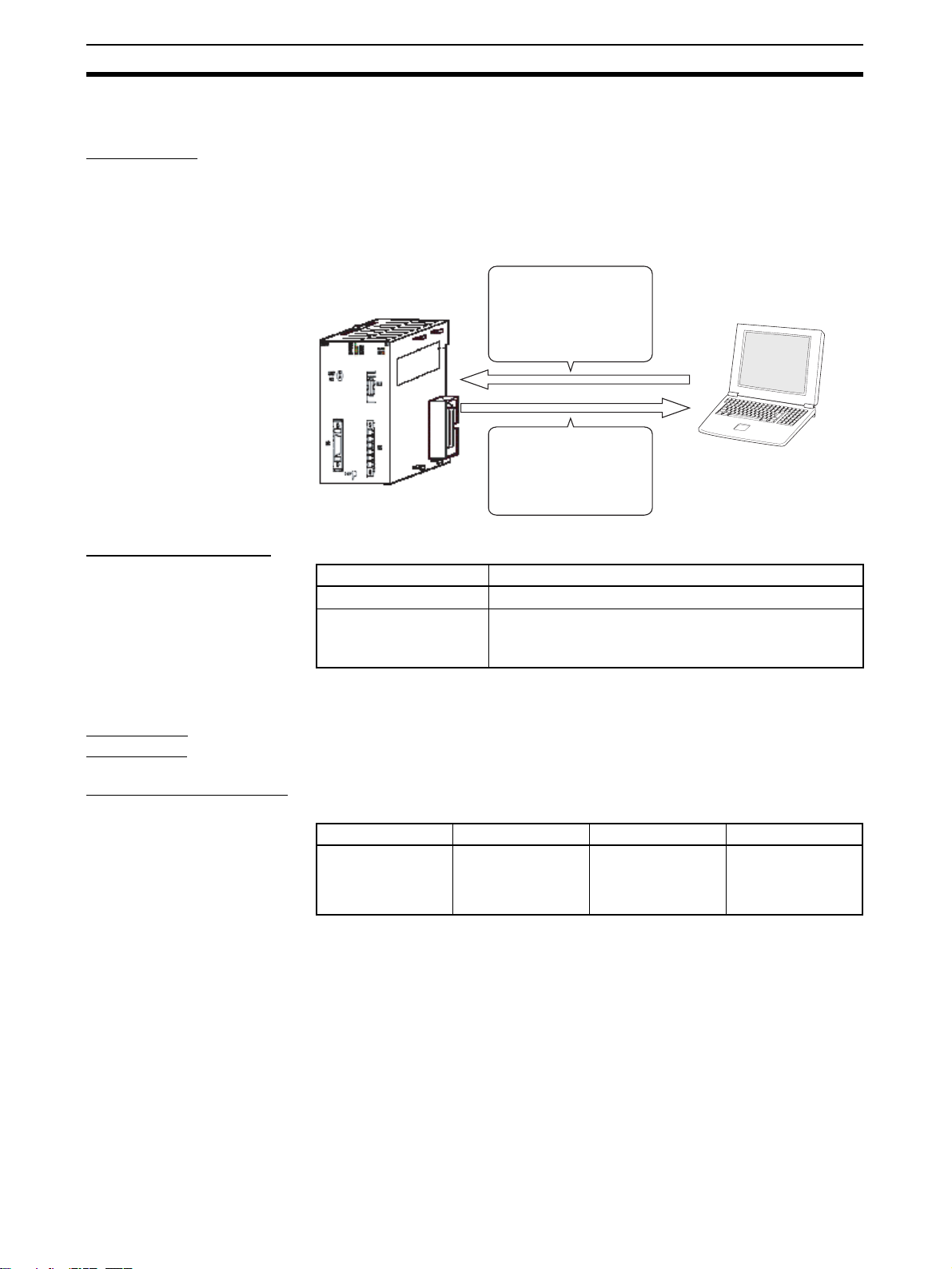
1-1 What is the CX-Motion-MCH?
Introduction The CX-Motion-MCH is a software package that can be used to set, create,
and print various data required to control MC Units (such as system parameters, position data, motion task programs, and CAM data), transfer the data to
and from the MC Unit, compare the data in the computer with the data in the
MC Unit, and monitor the operating status of the MC Unit.
The CX-Motion-MCH runs on Windows 2000, XP, Vista, or 7.
CS1W-MCH71
CJ1W-MCH71
Set and transfer the
various data and
programs required to
control the MC Unit.
Monitor the MC Unit's
operating status, e.g.,
error information or each
axis' present position.
Applicable MC Units The CX-Motion-MCH supports the following MC Units.
Model number Applicable PLCs
Applicable
Computers
CS1W-MCH71
CJ1W-MCH71 CJ2 CPU Units
Refer to 1-2 System Configuration for details on the system configuration.
Refer to the CX-One Setup Manual (W463) for the computer system require-
ments for the CX-Motion-MCH.
Recent versions of CS1 CPU Units (CS1
CJ1H/CJ1M CPU Units with unit version 2.0 or later, CPseries PLCs, and NSJ-series NSJ Controllers
Computer with Windows
operating system
@-CPU@@H)
Checking the Package Refer to the CX-One Setup Manual (W463) for details on the contents of the
CX-One package that includes the CX-Motion-MCH.
Cat. No. Model Manual name Contents
W463
CXONE-AL
@@D-V4
V4/AL
@@C-
CX-One Setup
Manual
Installation and
overview of CXOne FA Integrated
Tool Package.
2
Page 23
System Configuration Section 1-2
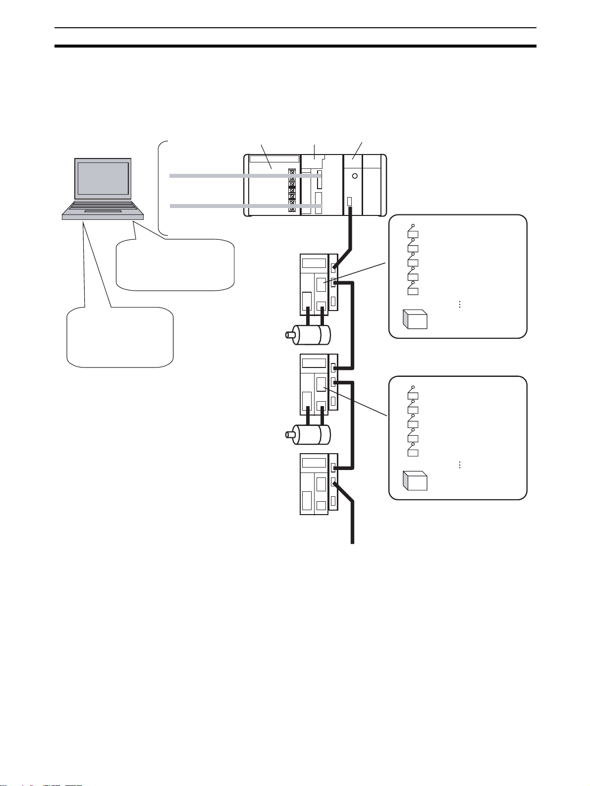
1-2 System Configuration
The system configuration for Motion Control Units is shown below.
CX-Motion-MCH
Editing/Transferring parameters
Monitoring
File management, etc.
CX-Programmer
Creating/Transferring
ladder program
Monitoring
File management, etc.
Toolbus/
Host Link
Power
Supply Unit
Servo Driver
Servomotor
Servo Driver
Servomotor
CJ Series
CPU Unit
MC Unit
(CJ1W-MCH71)
External inputs
Forward rotation limit input signal
Reverse rotation limit input signal
Origin input signal
Origin proximity input signal
Interrupt input signal
24-V DC power supply for
interface
External inputs
Forward rotation limit input signal
Reverse rotation limit input signal
Origin input signal
Origin proximity input signal
Interrupt input signal
Servo Driver
MECHATROLINK-II
(30 axes max.)
24-V DC power supply for
interface
3
Page 24
Function List Section 1-3
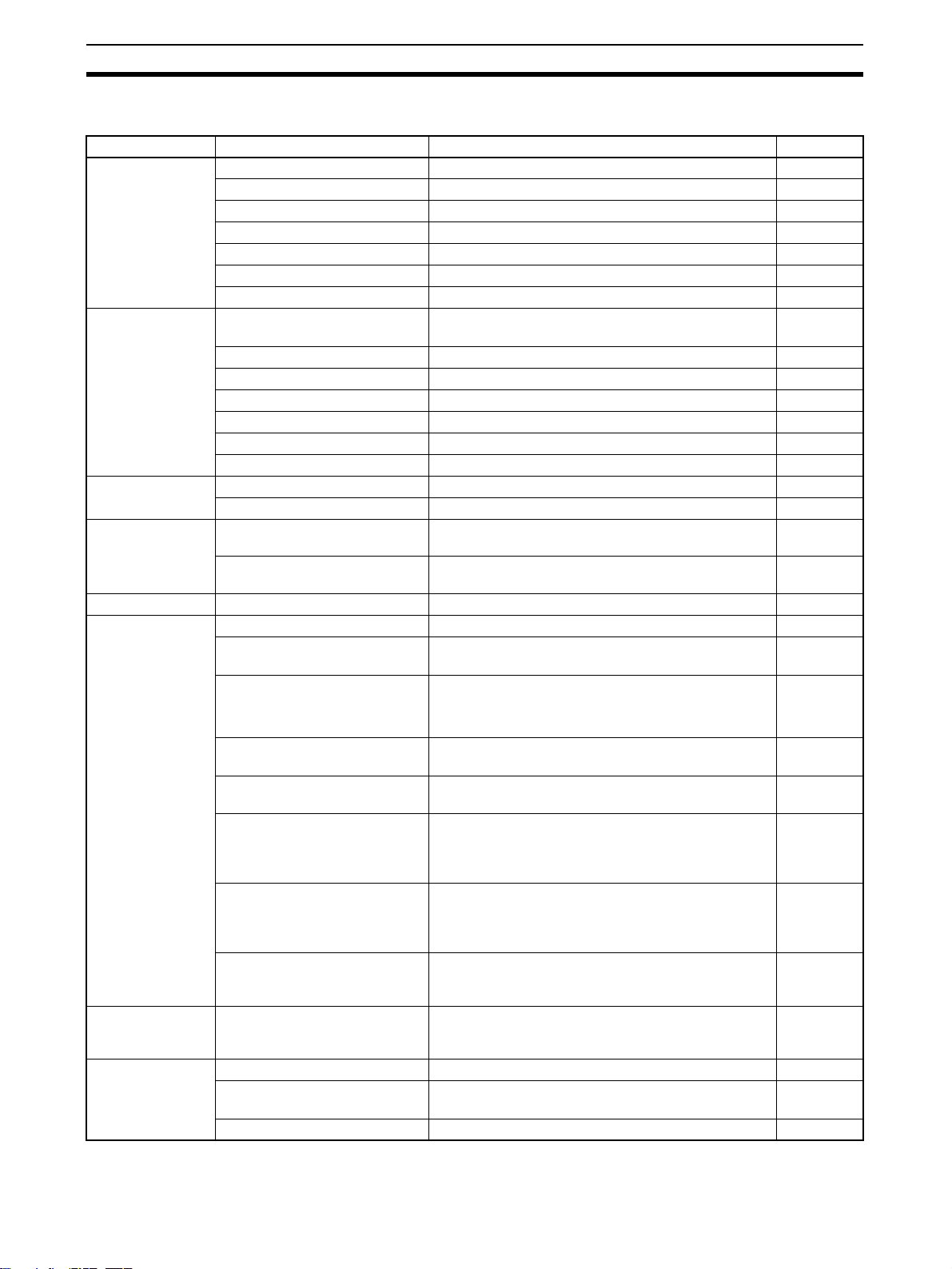
1-3 Function List
Group Function Details Reference
Editing projects Create project Used to create project files (*.mnh) page 30
Add/delete Motion Control Unit Used to add or delete MC Unit data in a project. page 31
Add/delete motion task Used to add or delete motion tasks in a project. page 32
Add/delete axis Used to add or delete axes in a project. page 33
Add/delete program Used to add or delete programs in a project. page 34
Add/delete subprogram Used to add or delete subprograms in a project page 35
Add/delete CAM table Used to add or delete CAM tables in a project. page 35
Editing data Edit system parameters Used to edit system parameters. (unit settings, tasks,
and settings)
Edit servo parameters Used to edit servo parameters. page 42
Edit motor parameters Used to edit motor parameters. page 42
Edit position data Used to edit position data. page 41
Edit program or subprogram Used to edit programs or subprograms. page 42
Edit CAM table Used to edit CAM tables. page 42
Edit symbol Used to edit symbols. page 41
Saving and reading project files
Importing and
exporting data
Printing Print Used to print various project data. page 88
Online Initial setting Used to setup CPU Unit or MC Unit. page 54
Data Trace Data Trace Used to set the trigger conditions and trace objects.
Backup and
Restore
Save project Used to save data as a project file (*.mnh). page 44
Read project Used to read a project file (*.mnh). page 44
Import Used to import MC-Miel for MCH files, position data,
programs, and CAM data.
Export Used to export position data, programs, and CAM
Communications setting Used to make settings for communications with the
Download
Upload
Compare
Write to flash memory Used to write RAM data inside the MC Unit to flash
Status monitor Used to display the error information, program num-
General monitor Used to display and change the MC Unit’s variables,
Test Run Used to execute the following operations: Servo
Debug the Program Used to debug the motion program. Motion programs
Backup from MC Used to backup the MC Unit. page 78
Restore to MC Used to restore the selected backup file to the MC
Verify Backup file with MC Unit Used to verify the backup file with the MC Unit. page 79
data.
PLC.
Used to download, compare, or upload system
parameters, servo parameters, position data, pro-
grams, and CAM data.
memory inside the MC Unit.
ber in progress, and axes’ present positions.
such as the system variables, global variables, input
variables, output variables, position data, and task
variables.
locks, JOG operations, STEP operations, origin
searches, origin returns, forced origins, setting an
absolute origin, teaching, and resetting errors.
can be debugged by setting break points and by
using single step execution.
The results of the trace operation are displayed
graphically.
Unit.
page 40
page 45
page 48
page 54
page 56
page 60
page 64
page 64
page 67
page 69
page 74
page 78
4
Page 25

Function List Section 1-3
Group Function Details Reference
Read Protection Set/Change Password Used to set/change passwords for read protection. page 83
Set/Release Protection Used to set/release protection on programs and cam
data and select data items that can be read through
the secondary password.
Switch User Used to switch the user. page 86
Error Error log Used to display the error log. page 92
Error information Used to display error code and error name. page 92
page 85
5
Page 26
Operation Procedure Section 1-4
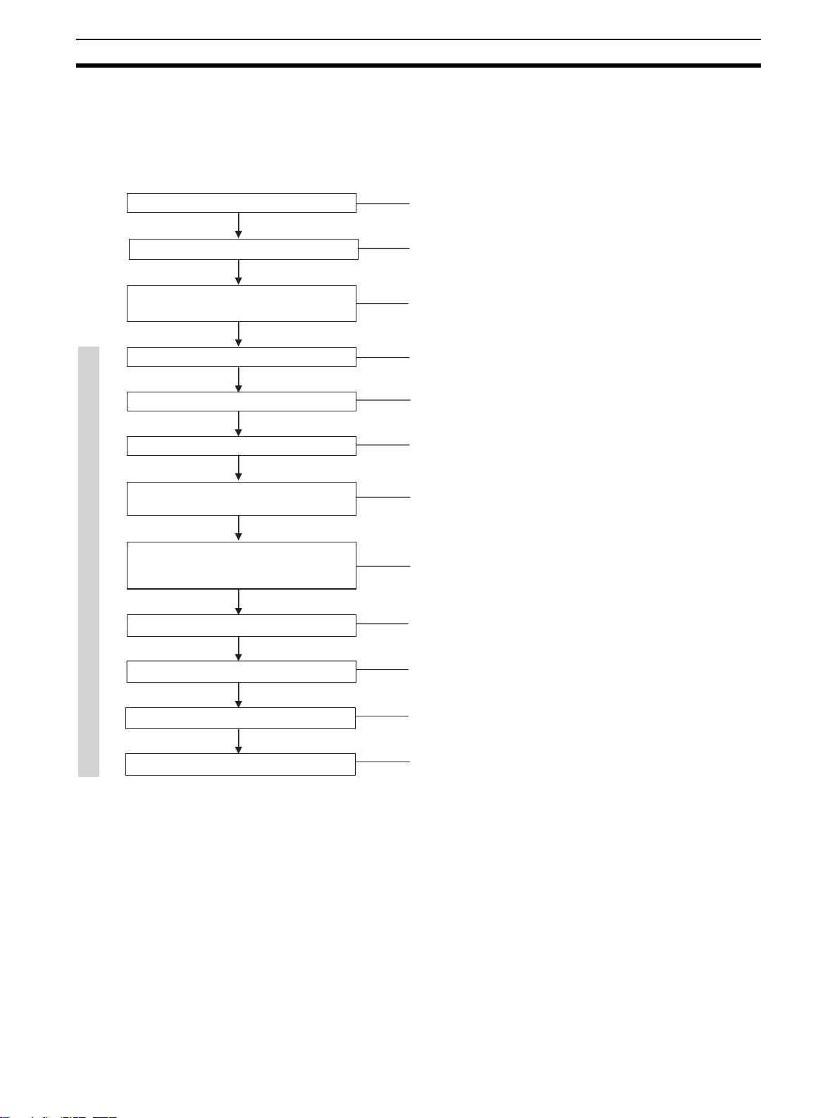
1-4 Operation Procedure
The following flowchart shows the procedures required to install CX-MotionMCH and CX-Server, create various data, transfer that data to MC Units, and
use in actual operations.
Installing CX-Motion-MCH
Installing CX-Server
Connecting to Built-in RS-232C port on
CPU Unit
Starting CX-Motion-MCH
Creating a New Project
Adding MC Unit to Project
CX-Motion-MCH Basic Window
Adding Tasks, Axes, Programs,
and CAM Data to MC Unit
Editing/Transferring MC Unit's System
Parameters, Servo Parameters, Position
Data, Programs, and CAM Data
Refer to page 8
Refer to page 8
Refer to page 8
Refer to page 14
Refer to page 30
Refer to page 31
Refer to page 33
Refer to SECTION 5 Editing Data and
page 56
Writing to Flash Memory
MC Unit Monitoring
Saving Project
Quitting CX-Motion-MCH
Refer to page 60
Refer to SECTION 8 Monitoring
Refer to page 44
Refer to page 15
6
Page 27

SECTION 2
Setup
This section provides information on installing the CX-Motion-MCH and CX-Server, and connecting to the PLC.
2-1 Installing and Uninstalling the Software. . . . . . . . . . . . . . . . . . . . . . . . . . . . . 8
2-2 Connecting to a PLC . . . . . . . . . . . . . . . . . . . . . . . . . . . . . . . . . . . . . . . . . . . . 8
2-2-1 Connecting to CS/CJ-series PLCs . . . . . . . . . . . . . . . . . . . . . . . . . . 8
2-2-2 Connecting to CP-series PLCs . . . . . . . . . . . . . . . . . . . . . . . . . . . . . 10
2-2-3 Connecting to CJ2 PLCs. . . . . . . . . . . . . . . . . . . . . . . . . . . . . . . . . . 11
7
Page 28
Installing and Uninstalling the Software Section 2-1
2-1 Installing and Uninstalling the Software
Required Software The following software must be installed on the same computer to use the CX-
Motion-MCH.
1. CX-Motion-MCH
2. CX-Server (the communications driver)
Installing CX-Motion-MCH Refer to the CX-One Setup Manual (Cat. No. W463) (supplied with the CX-
One FA Integrated Tool Package) for information on how to install or uninstall
the CX-Motion-MCH from the CX-One FA Integrated Tool Package.
Cat. No. Model Manual name Contents
W463 CXONE-AL@@C-V4/
AL@@D-V4
CX-One Setup Manual
An overview of the CXOne FA Integrated Tool
Package and the CX-One
installation procedure
2-2 Connecting to a PLC
To transfer the project data that was created using CX-Motion-MCH to the
Motion Control Unit, the personal computer and PLC (CPU Unit) have to be
physically connected with a cable and also connected online.
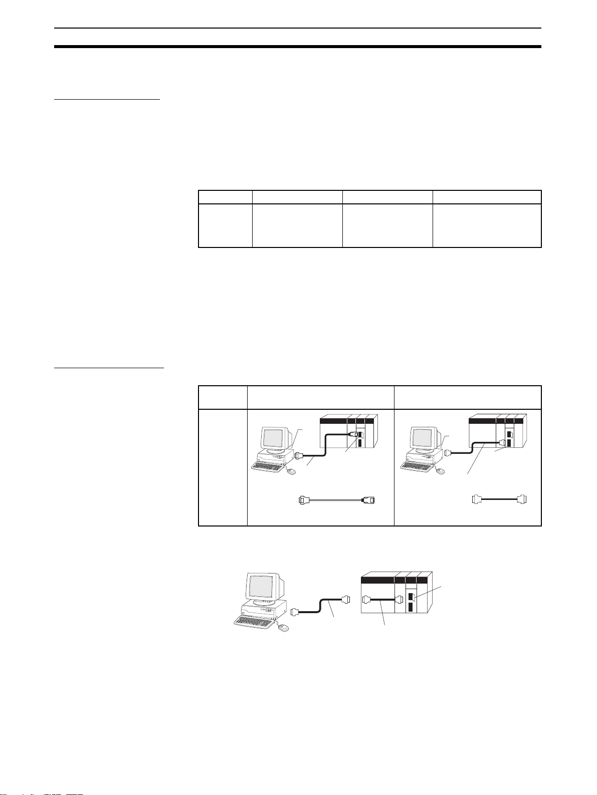
2-2-1 Connecting to CS/CJ-series PLCs
Connection Format Using either the Host Link (SYSMAC WAY) or Toolbus, connect the personal
computer to the peripheral port or RS-232C port on the PLC.
Personal
computer
IBM PC/
AT or
compatible
Note (1) The CS1W-CN118 cable is used as a relay cable to connect the personal
computer to the CPU Unit's peripheral port using the RS-232C cable
(model XW2Z-@@@@-@@) as shown below.
(2) There are two network protocols (serial communications modes), SYS-
MAC WAY and Toolbus, that can be used to connect the CX-Motion-MCH
Connecting to Peripheral Port Connecting to RS-232C Port
PC-98
01
B
X
N
E
C
CS1W-CN118 (See note 1.)
CS1W-CN226
CS1W-CN626
PC-9801
B
X
N
E
C
9-pin
male
9-pin
female
CS1W-CN118 (0.1 m) (See note 1.)
CS1W-CN226 (2.0 m)
CS1W-CN626 (6.0 m)
9-pin
female
Peripheral port
(10-pin female)
10-pin
RS-232C Cable
CS1W-CN118
PC
-9801
B
X
N
E
C
XW2Z-200S-CV/200S-V (2.0 m)
XW2Z-500S-CV/500S-V (5.0 m)
XW2Z-200S-CV/-200S-V
XW2Z-500S-CV/-500S-V
Peripheral Port
9-pin
male
9-pin
female
9-pin
male
RS-232C port
(9-pin female)
9-pin
female
9-pin
male
8
Page 29
Connecting to a PLC Section 2-2
to the PLC. The characteristics of the network protocols are as shown below.
Network type Characteristics
Toolbus Faster communications. If possible, use this network type.
• For CS/CJ Series, the baud rate on the peripherals can be
detected automatically, and be connected.
• Only 1 on 1 connection possible.
• For CX-Motion-MCH, it can also be connected to a modem.
SYSMAC WAY
(Host Link)
Used for communications with general host computers.
• Slower than Toolbus.
• Not only 1 on 1 connection, but also 1-many connection
possible.
• Connecting to a modem and optical adaptor possible.
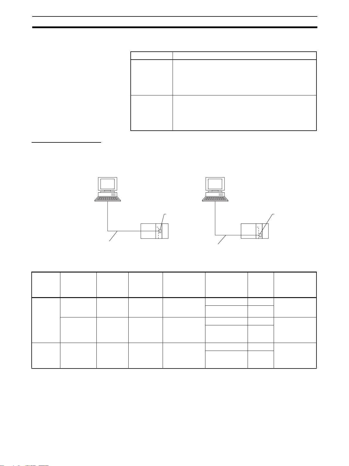
Connection Methods Use one of the following methods to connect the personal computer (CX-
Motion-MCH) and PLC (CPU Unit). It is also possible to connect the personal
computer to the port on the CS/CJ Series Serial Communications Unit. In that
case, the only network type that can be used is Host Link.
Connecting to Peripheral Port Connecting to RS-232C Port
IBM PC/AT or compatible IBM PC/AT or compatible
9-pin connector
CS1W-CN118 (0.1 m)
CS1W-CN226 (2.0 m)
CS1W-CN626 (6.0 m)
Connection Cables
Unit Port on Unit Computer Port on
CPU Unit Built-in
peripheral
port
Built-in RS232C port
(D-SUB, 9pin, female)
Serial
Communications
RS-232C port
(D-SUB, 9pin, female)
Unit
IBM PC/AT
compatible
IBM PC/AT
compatible
IBM PC/AT
compatible
D-SUB, 9pin, male
D-SUB, 9pin, male
D-SUB, 9pin, male
computer
Peripheral port
on CPU Unit
Network type
(serial commu-
nications
mode)
SYSMAC WAY
(Host Link)
SYSMAC WAY
(Host Link)
SYSMAC WAY
(Host Link)
9-pin connector
Built-in RS-232C port
on CPU Unit or Serial
Communications Unit
XW2Z-200S-CV (2.0 m)
XW2Z-500S-CV (5.0 m)
9-pin connector
Model number Length Remarks
CS1W-CN226 2 m --CS1W-CN626 6 m
XW2Z-200S-CV 2 m Uses anti-static
XW2Z-500S-CV 5 m
connector
XW2Z-200S-CV 2 m Uses anti-static
XW2Z-500S-CV 5 m
connector
Note When connecting the connectors of the above cables to the PLC's RS-232C
port, discharge any static build-up (e.g., by touching a grounded metal object)
before touching the connectors. Although XW2Z-@@@S-CV Cables use the
anti-static XM2S-0911-E Connector Hood (thus reducing the possibility of
static build-up), be sure to discharge any static as a safety precaution.
9
Page 30
Connecting to a PLC Section 2-2
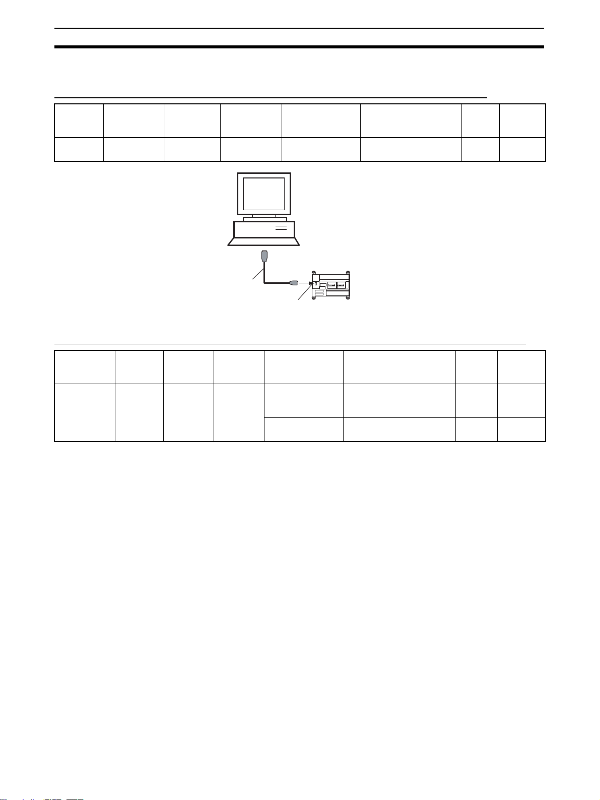
2-2-2 Connecting to CP-series PLCs
Connecting to USB Port on CPU Unit with Commercially Available US Cable
Unit Port on Unit Computer Port on
computer
CPU Unit USB port
(B connector)
IBM PC/AT
compatible
Commercially
available USB
cable
USB port
(A connector)
Serial communi-
cations mode
(network type)
USB Commercially available
IBM PC/AT or
compatible
USB port
CP-series CPU Unit
Peripheral
USB port
Model number Length Remarks
USB 1.1 or 2.0 cable
5 m
max.
---
Connecting to RS-232C Port on Serial Communications Board with RS-232C Cable
Unit Port on
CP1W-CIF01
Serial Communications
Board
Unit
RS-232C
port, Dsub 9-pin
female
Computer Port on
IBM PC/AT
compatible
computer
D-Sub, 9pin, male
Serial communi-
cations mode
(network type)
Toolbus (Peripheral) or SYSMAC
WAY (Host Link)
SYSMAC WAY
(Host Link)
Model number Length Remarks
XW2Z-200S-CV/500S-CV 2 m/5 m Uses anti-
static connector
XW2Z-200S-V/500S-V 2 m/5 m ---
10
Page 31

Connecting to a PLC Section 2-2
r
(
)
2-2-3 Connecting to CJ2 PLCs
USB or RS-232C Connection
Unit Port on Unit Computer Port on
computer
CPU Unit USB port
(B connector)
Built-in RS-
232C port, D-
IBM PC/AT
compatible
IBM PC/AT
compatible
USB port
(A connector)
D-sub 9-pin,
male
sub 9-pin
female
Note A Host Link (SYSMAC WAY) connection to an RS-232C port on the CPU Unit
or a Serial Communications Unit is not possible for CJ2 PLCs.
Serial communi-
cations mode
(network type)
USB Commercially available
Toolbus (See
note.)
USB RS-232C
Model number Length Remarks
5 m
USB 1.1 or 2.0 cable
max.
XW2Z-200S-CV/500S-CV2 m/
5 m
---
Uses
anti-static
connector
USB port
Commercially
available USB
cable
USB port
Ethernet Connection
Port on Unit Port on computer Serial communi-
cations mode
(network type)
Built-in EtherNet/
IP port
Ethernet port 100Base-TX/
10Base-T (Recommended:
100Base-TX)
IBM PC/AT or
compatible
Commercially
available twisted
cable based on
EtherNet/IP standard
Commercially
available switching hub
IBM PC/AT or
compatible
CJ2 CPU Unit
D-sub connector
(9-pin male)
XW2Z-200S-CV/500S-CV
Connecting Cable
CJ2 CPU Unit
Serial port
(RS-232C):
D-sub connecto
9-pin female
Model number Length Remarks
100 m (between
---
hub and node)
---
IBM PC/AT or
compatible
100Base-TX
twisted-pair cable
(straight)
Switching
hub
Built-in EtherNet/IP port
100Base-TX
twisted-pair cable
(straight)
CJ2 CPU Unit
11
Page 32

Connecting to a PLC Section 2-2
12
Page 33

This section describes each of the windows and basic operations.
3-1 Basic Operations . . . . . . . . . . . . . . . . . . . . . . . . . . . . . . . . . . . . . . . . . . . . . . . 14
3-2 Operations Listed by Purpose . . . . . . . . . . . . . . . . . . . . . . . . . . . . . . . . . . . . . 25
SECTION 3
Basic Operations
13
Page 34

Basic Operations Section 3-1
3-1 Basic Operations
Starting the CX-Motion-MCH
Starting the CX-Motion-MCH Using Start Special Application - Start with Settings Inherited from the I/O
Table Window Opened from the CX-Programmer That Was Installed from the CX-One
1,2,3... 1. Right-click a Motion Control Unit in the I/O Table Window and select Start
Special Application - Start with Settings Inherited from the pop-up
menu.
2. The CX-Motion-MCH will be started, a new project will be created, and a
Motion Control Unit will be added automatically. The Motion Control Unit
model will be inherited as shown below.
14
Page 35

Basic Operations Section 3-1
Starting the CX-Motion-MCH Using Start Special Application - Start Only from the I/O Table Window
Opened from the CX-Programmer That Was Installed from the CX-One
Right-click a Motion Control Unit in the I/O Table Window and select Start
Special Application - Start Only from the pop-up menu. The following win-
dow will be displayed.
Starting the CX-Motion-MCH from Windows Start Menu
Select Start - Programs - OMRON - CX-One - CX-Motion-MCH - CXMotion-MCH. The same window as when selecting Start Only will be dis-
played.
Quitting the CX-Motion-MCH
1,2,3... 1. Select File - Exit or click the at the top right corner of the window. After
2. Click the Yes Button to save the changes made. Click the No Button if it is
Main Menus
Main Menu Contents Keyboard
File Used to create or save projects. Alt+F
Edit Used to edit the MC Unit’s data. Alt+E
View Used to display or hide the Toolbars, Windows, or the
Insert Used to insert an MC Unit, motion task, axis, program,
Online Used to establish communications with the MC Unit. Alt+O
Program Used to compile the program. Alt+P
Debug Used to debug the program. Alt+D
Tools Used to change the fonts or toolbar. Alt+T
editing a project, if the project has not been saved, the following dialog box
will be displayed.
not necessary to save the changes. Click the Cancel Button to return to
the Basic Window without quitting CX-Motion-MCH.
shortcut
Alt+V
Status Bar.
Alt+I
subprogram, or CAM table into a project.
15
Page 36

Basic Operations Section 3-1
Main Menu Contents Keyboard
Windows Used to change the arrangement of open windows. Alt+W
Help Used to display help and version information. Alt+H
shortcut
Main Menu Items The names and functions for all of the menus are given in the table below.
When an item is selected, the dialog box for that function is displayed. Follow
the instructions in the dialog box.
Main
menu
File New Creates a new project file (*.mnh). Ctrl+N
Open Opens an existing project file (*.mnh). Ctrl+O
Close Closes the project file (*.mnh). --Save Saves the active project file (*.mnh)
Save As Saves the active project data in a
Import Imports MC-Miel for MCH files, posi-
Export Exports position data, motion pro-
Print Preview Shows a print preview image. --Print Prints project data. Ctrl+P
Exit Quits CX-Motion-MCH. Alt+F4
Item Contents Keyboard
shortcut
Ctrl+S
by overwriting the previous data.
---
project file (*.mnh) with a new name.
--tion data, motion programs, or CAM
data.
--grams, or CAM data.
16
Page 37

Basic Operations Section 3-1
Main
menu
Edit Undo Restores the previous data that was
Redo Restores the edited data that was
Cut Cuts the data selected in the program
Copy Copies the data selected in the
Paste Pastes the copied data in the param-
Delete Deletes an MC Unit, motion task,
Select All Selects all of the data displayed in the
Find Searches for text in the motion pro-
Find In Programs Searches for text in all motion pro-
Replace Replaces text in the motion program,
Go to Moves the cursor to the specified line
Edit Opens the editing window for param-
Item Contents Keyboard
edited in the parameter data, position
data, motion program, or CAM data
editing window.
undone in the parameter data, position data, motion program, or CAM
data editing window.
editing window.
parameter data, position data, motion
program, or CAM data editing window.
eter data, position data, motion program, or CAM data editing window.
axis, motion program, or CAM table.
parameter data, position data, motion
program, or CAM data editing window.
gram, position data, or CAM data
editing window.
grams.
position data, or CAM data editing
window.
number in the motion program or
position data editing window.
eter data, position data, motion program, or CAM data.
shortcut
Ctrl+Z
Ctrl+Y
Ctrl+X
Ctrl+C
Ctrl+V
Del
Ctrl+A
Ctrl+F
Ctrl+H
Ctrl+G
Ctrl+E
17
Page 38

Basic Operations Section 3-1
Main
menu
View Toolbar Standard Displays/hides the Standard Toolbar. ---
Windows Project
Item Contents Keyboard
Insert Displays/hides the Insert Toolbar. --Online Displays/hides the Online Toolbar. --Views Displays/hides the View Toolbar. --Servo Set-
tings
Program Displays/hides the Program Toolbar.
Debug Displays/hides the Debug Toolbar.
Workspace
Output Win-
dow
General
Watch Window
Debug
Watch Window
Status
Monitor
Test Run Displays/hides the Test Run Window. Alt+6
Displays/hides the Servo Settings
Toolbar.
Displays/hides the Project Workspace Window.
Displays/hides the Output Window. Alt+2
Displays/hides the General Watch
Window.
Displays/hides the Debug Watch
Window.
Displays/hides the Status Monitor
Window.
shortcut
---
Alt+1
Alt+3
Alt+4
Alt+5
18
Page 39

Basic Operations Section 3-1
Main
menu
View Status Bar Displays/hides the Status Bar. ---
Properties Opens the Properties Window for a
Servo
Parameters
Servo
Parameter Value
Insert MC Inserts an MC Unit to the project. ---
Task Inserts a motion task to the project. --Axis Inserts an axis to the project. --Program Inserts a program to the project. --Sub Program Inserts a subprogram to the project. --CAM Inserts a CAM table to the project. ---
Item Contents Keyboard
PLC, MC Unit, motion task, axis,
motion program or CAM table.
All Constants
Function
Selection
Constants
Gain
Related
Constants
Position
Related
Constants
Speed
Related
Constants
Torque
Related
Constants
Sequence
Related
Constants
Other Constants
Show Modified Only
Show Different Only
Show
Invalid Only
Displays all of the parameters in the
servo parameters editing window.
Displays only the function selection
constants in the servo parameters
editing window.
Displays only the gain-related constants in the servo parameters editing
window.
Displays only the position-related
constants in the servo parameters
editing window.
Displays only the speed-related constants in the servo parameters editing
window.
Displays only the torque-related constants in the servo parameters editing
window.
Displays only the sequence-related
constants in the servo parameters
editing window.
Displays only the other constants in
the servo parameters editing window.
Displays only those parameters with
changed values from the default in
the servo parameters editing window.
Displays only those parameters with
values different between the computer and MC Unit in the servo
parameters editing window.
Displays only those parameters with
invalid values (out-of-range settings)
in the servo parameters editing window.
shortcut
---
---
---
---
---
---
---
---
---
---
---
---
19
Page 40

Basic Operations Section 3-1
Main
menu
Online Work Online Switches between online/offline. ---
Monitor Mode Switches between normal mode and
Unit Information Displays the Unit information. --Transfer To MC Transfers parameters and other data
Batch
Transfer
Write To Flash Saves the MC Unit’s parameters and
Clear Memory Initializes the MC Unit’s parameters
Error Log Displays the MC Unit’s error log. --Data Trace Displays the Data Trace Window.
Backup
and
Restore
Read Protection
Program
Compile Compiles the program. F7
Item Contents Keyboard
monitor mode
to the MC Unit.
From MC Transfers parameters and other data
From Servo Transfers servo parameters from the
Compare Compares parameters and data val-
Compare
Servo
Parameter
with MC
Compare
Servo
Parameter
with Servo
To All MC Transfers parameters and other data
From All MCTransfers parameters and other data
Backup
from MC
Restore to MCRestores the selected backup file to
Veri fy
Backup file
with MC
Unit
Set/Change
Password
Set/
Release
Protection
Switch User Switches the user.
from the MC Unit.
Servo Driver.
ues between the MC Unit and computer.
Compares servo parameter values
between the MC Unit and computer.
Compares servo parameter values
between the Servo Driver and computer.
altogether to the MC Unit.
altogether from the MC Unit.
other data.
and other data.
Backs up the MC Unit.
the MC Unit.
Verifies the backup file with the MC
Unit.
Sets/changes the passwords for read
protection.
Sets/releases protection on programs
and cam data and selects data items
that can be read through the secondary password.
shortcut
---
---
---
---
---
---
---
---
---
---
20
Page 41

Basic Operations Section 3-1
Main
menu
Debug Insert/Remove Break
Point
Remove All Break
Points
Go Debugs the program. F5
Step Into Debugs the program one step at a
Stop Stops debugging the program. Shift+F5
Run To Cursor Debugging will stop one line before
Tools Customize Customizes the Toolbar. ---
Font Options Sets the font. ---
Windows
Help Help Contents Displays the table of contents for
Close All Closes all open editing windows. --Next Docked Moves the focus to the next window. Alt+0
Previous Docked Moves the focus to the previous win-
Cascade Stacks the open editing windows. --Tile Horizontally Horizontally tiles the open editing
Tile Vertically Vertically tiles the open editing win-
Search for Help On Displays the help search topics. --Command Reference Displays the command reference
Parameter Reference Displays the parameter reference
Value Reference Displays the value reference help. --Troubleshooting Displays the troubleshooting help.
Online Registration Connects to the OMRON online user
About CX-Motion-MCH Displays the version information. ---
Item Contents Keyboard
shortcut
Inserts/removes a break point. F9
Removes all break points. Ctrl+Shift+
F9
F11
time.
Ctrl+F10
the cursor.
Alt+Shift+0
dow.
--windows.
--dows.
F1
help.
--help.
--help.
--registration.
Toolbars
Standard Toolbar
Functions can be executed directly by clicking on the appropriate icon on the
toolbar. The functions that can be executed from the toolbars are given below.
1 2 3 4 5 6 7 8 9 10 11 12 13 14 15 16 17 18
Number Function
(1) Create a new project.
(2) Open an existing project.
(3) Save the active project by overwriting the existing project file.
(4) Export to file.
(5) Import from file.
(6) Display the print preview.
(7) Print
21
Page 42

Basic Operations Section 3-1
Number Function
(8) Cut
(9) Copy
(10) Paste
(11) Undo
(12) Redo
(13) Find
(14) Find In Programs
(15) Replace
(16) Edit
(17) Display CX-Motion-MCH information.
(18) Display the table of contents for help.
View Toolbar
1 2
Number Function
(1) Display/hide the Project Workspace Window.
(2) Display/hide the Output Window.
(3) Display/hide the General Watch Window.
(4) Display/hide the Debug Watch Window.
(5) Display/hide the Status Monitor Window.
(6) Display the Properties Window.
3
6
4
5
Insert Toolbar
Online Toolbar
1 2 3 4 5 6
Number Function
(1) Insert an MC Unit.
(2) Insert a motion task.
(3) Insert an axis.
(4) Insert a program.
(5) Insert a subprogram.
(6) Insert a CAM table.
1 2 3 4 5 6 7 8 9 10 11 12 13 14
Number Function
(1) Transfer to MC Unit.
(2) Transfer from MC Unit.
(3) Transfer from Servo Driver.
15
22
Page 43

Basic Operations Section 3-1
Number Function
(4) Compare with MC Unit.
(5) Compare servo parameters with MC Unit.
(6) Compare servo parameters with Servo Driver.
(7) Batch transfer to MC Unit.
(8) Batch transfer from MC Unit.
(9) Save in flash memory.
(10) Clear memory.
(11) Display error log.
(12) Display the Data Trace Window.
(13) Delete
(14) Switch between online/offline.
(15) Switch between normal mode and monitor mode.
Program Toolbar
Debug Toolbar
Servo Settings Toolbar
1 2 3
Number Function
(1) Compile the program.
(2) Insert/remove a break point.
(3) Remove all break points.
Number Function
(1) Select the task number.
(2) Display/hide the Test Run Window.
(3) Debug the program.
(4) Stop debugging the program.
(5) Debug the program one step at a time.
(6) Debugging will stop one line before the cursor.
(7) Stop all axes.
1
2 3 4 5
6
7
2
1
Number Function
(1) Show Modified Only
(2) Show Different Only
(3) Show Invalid Only
3
23
Page 44

Basic Operations Section 3-1
Status Bar The following information is displayed on the status bar.
1
Number Function
(1) Displays messages regarding the status of data being edited or trans-
(2) Displays a bar graph showing the progress of a data transfer.
(3) Displays the cursor position in the program editing window.
(4) Indicates the online/offline status.
(5) Indicates the keyboard Caps Lock status.
(6) Indicates the keyboard Num Lock status.
2
ferred.
3
4
5
6
Help
Displaying the Help Contents
1,2,3... 1. Select Help - Help Contents. The table of contents for help will be dis-
played.
2. Click a topic to display information. The contents related to that topic will
be displayed.
Displaying CX-MotionMCH Version Information
Select Help - About CX-Motion-MCH. The CX-Motion-MCH version information will be displayed.
24
Page 45

Operations Listed by Purpose Section 3-2
3-2 Operations Listed by Purpose
Operations Listed by Purpose
Function (Purpose) Operation Keyboard
shortcut
Project
Creating a new project Select File - New.Ctrl+N30
Opening a project Select File - Open.Ctrl+O44
Toolbar
icon
Page
Saving a project (overwriting)
Saving a project with a
different name
Close a project Select File - Close. --- --- --Quitting CX-Motion-
MCH
Adding an MC Unit to
the project
Importing a file cre-
ated by MC-Miel for
MCH
Importing position
data from a file
Exporting position
data to a file
Importing a program
from a file
Exporting a program
to a file
Importing a subprogram from a file
Exporting a subprogram to a file
Importing a CAM table
from a file
Exporting a CAM table
to a file
Displaying properties Select a PLC, MC Unit, task, Servo Driver, program, sub-
Adding a motion task Select Tasks and select Insert - Task or right-click and
Deleting a motion task Select Tasks and select Edit - Delete or right-click and
Adding an axis Select Axes and select Insert - Axis or right-click and
Deleting an axis Select the axis and select Edit - Delete or right-click and
Adding a program Select Motion Programs or Programs and select Insert -
Deleting a program Select the program and select Edit - Delete or right-click
Adding a subprogram Select Motion Programs or Sub Programs and select
Select File - Save.Ctrl+S44
Select File - Save As. --- --- 44
Select File - Exit. --- --- 15
Select the PLC and select Insert - MC or right-click and
select Insert MC.
Select the PLC and select File - Import or right-click and
select Import From Miel.
Select the position data and select File - Import or rightclick and select Import.
Select the position data and select File - Export or rightclick and select Export.
Select Motion Programs, Programs, or the program and
select File - Import or right-click and select Import Pro-
gram or Import.
Select the program and select File - Export or right-click
and select Export.
Select Motion Programs, Programs or the sub program
and select File - Import or right-click and select Import
Sub Program or Import.
Select the subprogram and select File - Export or rightclick and select Export.
Select a CAM or CAM table and select File - Import or
right-click and select Import CAM or Import.
Select the CAM table and select File - Export or right-click
and select Export.
program, or CAM table and select View - Properties or
right-click and select Properties.
select Insert Task.
select Delete.
select Insert Axis.
select Delete.
Program or right-click and select Insert Program.
and select Delete.
Insert - Sub Program or right-click and select Insert Sub
Program.
--- 31
--- 45
--- 45
--- 48
--- 46
--- 48
--- 46
--- 49
--- 47
--- 50
--- 22
--- 32
Del 32
--- 33
Del 34
--- 34
Del 35
--- 35
25
Page 46

Operations Listed by Purpose Section 3-2
Function (Purpose) Operation Keyboard
Deleting a subprogram
Adding a CAM table Select CAM and select Insert - CAM or right-click and
Deleting a CAM table Select the CAM table and select Edit - Delete or right-click
Displaying a print preview
Printing parameters or
programs
Editing parameters
Editing Unit Parameters
Editing task parameters
Editing axis parameters
Editing servo parameters
Editing motor parameters
Editing data
Editing position data Select Position Data and select Edit - Edit, right-click and
Editing a program Select Programs and select Edit - Edit, right-click and
Editing a subprogram Select Sub Programs and select Edit - Edit, right-click and
Compiling a program Select the program or subprogram and select Edit - Com-
Editing a CAM table Select the CAM table and select Edit - Edit, right-click and
Online operations
Starting communications with PLC
Setting communications with PLC
Transferring selected
data to the MC Unit
Transferring selected
data from the MC Unit
Transferring data to all
the MC Units
Transferring data from
all the MC Units
Transferring from the
Servo Driver
Comparing parameters or data with MC
Unit
Comparing servo
parameters with MC
Unit
Select the subprogram and select Edit - Delete or rightclick and select Delete.
select Insert CAM.
and select Delete.
Select File - Print Preview. --- 21
Select File - Print.Ctrl+P92
Select Unit Settings and select Edit - Edit, right-click and
select Edit, or double-click.
Select the task and select Edit - Edit, right-click and select
Edit, or double-click.
Select settings and select Edit - Edit, right-click and select
Edit, or double-click.
Select servo settings and select Edit - Edit, right-click and
select Edit, or double-click.
Select motor settings and select Edit - Edit, right-click and
select Edit, or double-click.
select Edit, or double-click.
select Edit, or double-click.
select Edit, or double-click.
pile or right-click and select Compile.
select Edit, or double-click.
Select the PLC and select Online - Work Online or rightclick and select Work Online.
Select the PLC and select View - Properties or right-click
and select Properties.
Select the parameters or data to be transferred and select
Online - Transfer - To MC.
Select the parameters or data to be transferred and select
Online - Transfer - From MC.
Select the PLC and select Online - Batch Transfer - To
All MC.
Select the PLC and select Online - Batch Transfer - From
All MC.
Select Servo Settings and select Online - Transfer - From
Servo or right-click and select Transfer - From Servo.
Select the MC Unit to be compared and select Online -
Transfer - Compare or right-click and select Transfer Compare.
Select the Servo Settings and select Online - Transfer Compare Servo Parameter with MC or right-click and
select Transfer - Compare Servo Parameter with MC.
shortcut
Del 36
--- 37
Del 38
Ctrl+E 41
Ctrl+E 42
Ctrl+E 42
Ctrl+E 42
Ctrl+E 42
Ctrl+E 41
Ctrl+E 42
Ctrl+E 42
F7 23
Ctrl+E 42
Ctrl+W 55
--- 54
--- 56
--- 57
--- 61
--- 61
--- ---
--- 58
--- ---
Toolbar
icon
Page
26
Page 47

Operations Listed by Purpose Section 3-2
Function (Purpose) Operation Keyboard
Comparing servo
parameters with Servo
Driver
Initializing memory Select the MC Unit and select Online - Clear Memory. --- 61
Writing to flash memory
Monitoring the MC
Unit’s status or errors
Monitoring variables Select the MC Unit and select View - Windows - General
Displaying error log Select the MC Unit and select Online - Error Log. --- 92
Debugging the program
Executing Test Run
operations, such as
JOG operations
Tracing data Select the MC Unit and select Online - Data Trace.
Backing up the MC
Unit
Restoring a backup
file to the MC Unit
Verifying a backup file
with the MC Unit
Setting and changing
passwords for protection
Setting and releasing
protection
Switching user Select the MC Unit and select Online - Read Protection -
Displaying settings
Displaying/hiding Toolbar
Displaying/hiding the
Project Workspace
Displaying/hiding the
Output Window
Displaying/hiding Status Bar
Displaying/hiding the
Debug Watch Window
Displaying/hiding the
Test Run
Help
Displaying the MC
Unit’s model and version
Displaying help Select Help - Help Contents. F1 24
Select Servo Settings and select Online - Transfer - Com-
pare Servo Parameter with Servo or right-click and select
Transfer - Compare Servo Parameter with Servo.
Select the MC Unit and select Online - Write To Flash. --- 60
Select the MC Unit and select View - Windows - Status
Monitor.
Watch Window.
Select the MC Unit and select Online - Monitor Mode.
Select the MC Unit and select Online - Monitor Mode.
Select the MC Unit and select Online - Backup and
Restore - Backup from MC.
Select the MC Unit and select Online - Backup and
Restore - Restore to MC.
Select the MC Unit and select Online - Backup and
Restore - Verify Backup files with MC.
Select the MC Unit and select Online - Read Protection -
Set/Change Password.
Select the MC Unit and select Online - Read Protection Set/Release Protection.
Switch User.
Select View - ToolBar and select Standard, Insert,
Online, View or Servo Settings.
Select View - Windows - Project Workspace.Alt+1 22
Select View - Windows - Output Window.Alt+2 22
Select View - Status Bar. --- --- 19
Select View - Window - Debug Watch Window.Alt+4 69
Select View - Window - Test Run.Alt+667
Select the MC Unit and select Online - Unit Information. F1 --- 60
shortcut
--- ---
Alt+5 64
Alt+3 64
--- --- 18
Toolbar
icon
--- 78
--- 78
--- 79
--- 83
--- 85
--- 86
Page
Displaying the CXMotion-MCH
Select Help - Search for Help On. F1 --- 21
Select Help - About CX-Motion-MCH. --- 24
27
Page 48

Operations Listed by Purpose Section 3-2
28
Page 49

SECTION 4
Creating Projects
This section provides information on creating projects and adding MC Units, tasks, axes, programs, subprograms, and
CAM tables.
4-1 Creating a New Project . . . . . . . . . . . . . . . . . . . . . . . . . . . . . . . . . . . . . . . . . . 30
4-2 Adding and Deleting MC Units . . . . . . . . . . . . . . . . . . . . . . . . . . . . . . . . . . . 31
4-3 Adding and Deleting Tasks . . . . . . . . . . . . . . . . . . . . . . . . . . . . . . . . . . . . . . . 32
4-4 Adding and Deleting Axes . . . . . . . . . . . . . . . . . . . . . . . . . . . . . . . . . . . . . . . 33
4-5 Adding and Deleting Programs. . . . . . . . . . . . . . . . . . . . . . . . . . . . . . . . . . . . 34
4-6 Adding and Deleting Subprograms. . . . . . . . . . . . . . . . . . . . . . . . . . . . . . . . . 35
4-7 Adding and Deleting CAMs . . . . . . . . . . . . . . . . . . . . . . . . . . . . . . . . . . . . . . 37
29
Page 50

Creating a New Project Section 4-1
4-1 Creating a New Project
Follow the procedure below to create a new project on the CX-Motion-MCH
Basic Window. When a new CX-Motion-MCH project is being created, a dialog box will be displayed for adding an MC Unit after setting the PLC model.
1,2,3... 1. On the CX-Motion-MCH Basic Window, select File - New, press the Ctrl+N
Keys, or click in the toolbar.
2. The Change PLC Dialog Box will be displayed. Set the model number of
the PLC being used.
3. The Insert MC Dialog Box will be displayed. Set the model number of the
MC Unit being used.
30
Page 51

Adding and Deleting MC Units Section 4-2
4-2 Adding and Deleting MC Units
Adding MC Units to
Projects
1,2,3... 1. Select the PLC icon in the project tree and select Insert - MC or click
Follow the procedure below to add a Motion Control Unit to the project.
in the toolbar. It is also possible to right-click the PLC icon in the project
tree and select Insert MC from the pop-up menu.
2. Set the MC Unit’s name, model number, and unit number (unit number as
a CPU Bus Unit) in the Insert MC Dialog Box.
3. Click the OK Button. The MC Unit will be added to the project.
Deleting MC Units
1,2,3... 1. Select the unwanted MC Unit icon ( ) in the project tree and select Edit
- Delete, click in the toolbar, or press the Delete Key. It is also possi-
ble to right-click the unwanted MC Unit icon in the project tree and select
Delete from the pop-up menu.
2. A dialog box will be displayed to confirm the deletion. Click the Yes Button
to delete the MC Unit. The selected MC Unit will be deleted from the
project tree.
31
Page 52

Adding and Deleting Tasks Section 4-3
4-3 Adding and Deleting Tasks
Adding a Task to an
MC Unit
1,2,3... 1. Select the MC Unit or Tasks Icon in the project tree and select Insert - Task
Deleting a Task from
an MC Unit
The following procedure adds an individual task to a project’s MC Unit.
Up to 8 individual tasks can be added to one MC Unit. Each MC Unit must
have at least one task.
or click in the toolbar. It is also possible to right-click the Tasks Icon
in the project tree and select Insert Task from the pop-up menu.
2. An individual task will be added to the MC Unit’s Tasks folder.
The following procedure deletes a registered task from an MC Unit.
The lowest individual task will be deleted from the MC Unit’s registered tasks.
32
1,2,3... 1. Select the Ta sk s Icon ( ) in the project tree and select Edit - Delete, click
in the toolbar, or press the Delete Key. It is also possible to right-click
the Tasks Icon and select Delete from the pop-up menu.
2. A dialog box will be displayed to confirm the deletion. Click the Yes Button
to delete the task. The lowest individual task will be deleted from the MC
Unit’s registered tasks.
Page 53
Adding and Deleting Axes Section 4-4
4-4 Adding and Deleting Axes
Adding an Axis to an
MC Unit
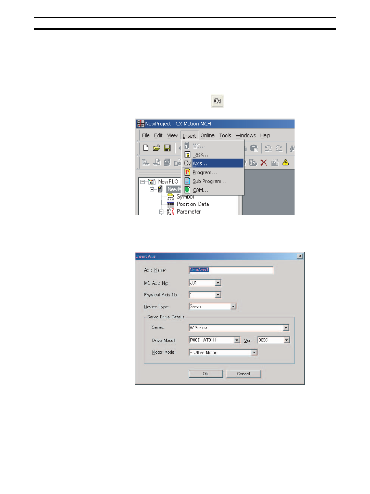
1,2,3... 1. Select the MC Unit, or the Parameter or Axes Icon in the project tree, and
The following procedure adds an individual axis to a project’s MC Unit.
Up to 32 individual axes can be added to one MC Unit, of which 30 axes can
be physical.
select Insert - Axis or click in the toolbar. It is also possible to right-
click the Axes Icon and select Insert Axis from the pop-up menu.
2. The Insert Axis Dialog Box will be displayed. Set the Axis’ name, axis number, physical axis number, and device type. Also set the Servo Driver series, Servo Driver model, Servo Driver version, and motor model if Servo
is set as the device type.
3. Click the OK Button. The individual axis will be added to the MC Unit.
33
Page 54

Adding and Deleting Programs Section 4-5
Deleting an Axis from
an MC Unit
1,2,3... 1. Select the unwanted axis icon ( ) in the project tree and select Edit - De-
The following procedure deletes a registered axis from an MC Unit.
lete, click in the toolbar, or press the Delete Key. It is also possible to
right-click the unwanted axis icon and select Delete from the pop-up menu.
2. A dialog box will be displayed to confirm the deletion. Click the Yes Button
to delete the axis. The selected axis will be deleted from the axes registered in the MC Unit.
4-5 Adding and Deleting Programs
Adding a Program to
an MC Unit
1,2,3... 1. Select the MC Unit or the Motion Programs, or Program Icon in the project
The following procedure adds an individual program to a project’s MC Unit.
Individual programs can be added with program numbers from 0 to 499.
tree and select Insert - Program or click in the toolbar. It is also possible to right-click the Motion Programs or Programs Icon and select Insert
Program from the pop-up menu.
34
Page 55

Adding and Deleting Subprograms Section 4-6
2. The Insert Program Dialog Box will be displayed. Set the program name,
program number, comment, and axis declaration.
3. Click the OK Button. The individual program will be added to the MC Unit.
Deleting a Program
from an MC Unit
1,2,3... 1. Select the unwanted program icon ( ) in the project tree and select Edit
The following procedure deletes a registered program from an MC Unit.
- Delete, click in the toolbar, or press the Delete Key. It is also possi-
ble to right-click the unwanted program icon and select Delete from the
pop-up menu.
2. A dialog box will be displayed to confirm the deletion. Click the Yes Button
to delete the program. The selected program will be deleted from the programs registered in the MC Unit.
4-6 Adding and Deleting Subprograms
Adding a Subprogram
to an MC Unit
The following procedure adds an individual subprogram to a project’s MC
Unit.
Individual subprograms can be added with program numbers from 500 to 599.
35
Page 56

Adding and Deleting Subprograms Section 4-6
1,2,3... 1. Select the MC Unit or the Motion Programs or Sub Programs Icon in the
project tree and select Insert - Sub Program or click in the toolbar. It
is also possible to right-click the Motion Programs or Sub Programs Icon
and select Insert Sub Program from the pop-up menu.
2. The Insert Sub Program Dialog Box will be displayed. Set the subprogram
name, subprogram number, comment, and axis declaration.
Deleting a
Subprogram from an
MC Unit
3. Click the OK Button. The individual subprogram will be added to the MC
Unit.
The following procedure deletes a registered subprogram from an MC Unit.
36
Page 57

Adding and Deleting CAMs Section 4-7
1,2,3... 1. Select the unwanted subprogram icon ( ) in the project tree and select
Edit - Delete, click in the toolbar, or press the Delete Key. It is also
possible to right-click the unwanted subprogram icon and select Delete
from the pop-up menu.
2. A dialog box will be displayed to confirm the deletion. Click the Yes Button
to delete the subprogram. The selected subprogram will be deleted from
the subprograms registered in the MC Unit.
4-7 Adding and Deleting CAMs
Adding CAM Tables to
an MC Unit
1,2,3... 1. Select the MC Unit or the CAM Icon in the project tree and select Insert -
The following procedure adds individual CAM tables to a project’s MC Unit.
Up to 32 CAM tables can be added to one MC Unit.
CAM or click in the toolbar. It is also possible to right-click the CAM
Icon and select Insert CAM from the pop-up menu.
2. The Insert CAM Dialog Box will be displayed. Set the CAM name, CAM
number, and displacement decimal point position.
3. Click the OK Button. The CAM table will be added to the MC Unit.
37
Page 58

Adding and Deleting CAMs Section 4-7
Deleting CAM Tables
from an MC Unit
1,2,3... 1. Select the unwanted CAM table icon ( ) in the project tree and select
The following procedure deletes a registered CAM table from an MC Unit.
Edit - Delete, click in the toolbar, or press the Delete Key. It is also
possible to right-click the unwanted CAM table icon and select Delete from
the pop-up menu.
2. A dialog box will be displayed to confirm the deletion. Click the Yes Button
to delete the CAM table. The selected CAM table will be deleted from the
CAMs registered in the MC Unit.
38
Page 59

SECTION 5
Editing Data
This section describes the operations used to edit data.
This manual shows how to edit data, but does not describe the functions of the data and parameters. For details on the
various data settings, refer to the MC Unit’s Operation Manual.
5-1 Editing Data . . . . . . . . . . . . . . . . . . . . . . . . . . . . . . . . . . . . . . . . . . . . . . . . . . 40
39
Page 60

Editing Data Section 5-1
5-1 Editing Data
This section describes how to edit data only. For details on the MC Unit’s setting contents, Unit parameters, and Servo Parameters, refer to the CS1W-
MCH71 Motion Control Unit Operation Manual (W419) or CJ1W-MCH71
Motion Control Unit Operation Manual (W435).
Overview of the
Editing Windows
The following table provides an overview of the editing windows.
Editing window Overview
Symbol Names and comments can be set for system parameters and
variable addresses. Those names can be used to reference
parameters in the General Watch Window, programs, and
subprograms.
Position Data Position data can be edited. The names edited here can be
used to reference the data in the General Watch Window, pro-
grams and subprograms.
Unit Settings Unit parameters can be edited.
Zone Settings Zone parameters can be edited.
This function can be used in an MC Unit with the unit version
3.0 or later.
Tasks Motion task parameters can be edited.
All of the current motion task parameters are displayed in the
Edit Motion Task Parameters Window.
Settings Axis parameters can be edited.
All of the current axis parameters are displayed in the Edit
Axis Parameters Window.
Servo Settings Parameters in the Servo Driver can be edited.
Motor Settings Motor parameters can be edited.
Programs The motion task’s program can be edited.
Sub Programs The motion task’s subprograms can be edited.
CAM Data Imported CAM table can be edited.
Editing Data This section describes the main editing methods.
■ Direct Input
Input data directly.
The allowed setting range is displayed on the left side of the Status Bar, as
shown in the following diagram.
■ Drop-down List
Either click the ▼ button or press the Alt+i Keys. Click the desired setting
directly from the drop-down list to select it.
40
Page 61

Editing Data Section 5-1
■ Drop-down List (Check Boxes)
Either click the ▼ button or press the Alt+i Keys. Select the box to the left of
the desired setting to select that option.
Editing Symbols
■ Displaying the Window
With the project tree displayed, either double-click the desired MC Unit’s symbol or select the desired MC Unit’s symbol and press the Enter Key.
■ Switching between Edit Symbols Tabs
Either system parameters or variables can be edited by clicking the corresponding tab.
■ Editing in the System Parameters Tab
To edit the names of system parameters, click the System Parameters Tab
and either double-click the desired parameter or right-click the desired parameter and select Edit from the pop-up menu.
Editing Position Data
Editing Unit Settings
Editing Zone Settings
■ Editing in the Variables Tab
To edit the names of variables, click the Variables Tab and either double-click
the desired parameter or right-click the desired parameter and select Edit
from the pop-up menu.
A new variable can be added by right-clicking on the Variables Tab Page and
selecting Insert from the pop-up menu. Select or input the name, variable
type, data type, address, and comment in the displayed New Symbol Dialog
Box, and then press the OK Button.
■ Displaying the Window
With the project tree displayed, either double-click the desired MC Unit’s position data or select the desired MC Unit’s position data and press the Enter
Key.
■ Displaying the Window
With the project tree displayed, either double-click the desired MC Unit’s Unit
parameters or select the desired MC Unit’s Unit parameters and press the
Enter Key.
■ Displaying the Window
With the project tree displayed, either double-click the desired MC Unit's zone
parameters or select the desired MC Unit's zone parameters and press the
Enter Key.
41
Page 62

Editing Data Section 5-1
Editing Tasks
■ Displaying the Window
With the project tree displayed, either double-click the desired MC Unit’s task
or select the desired MC Unit’s task and press the Enter Key.
All of the current motion task parameters will be displayed in the Edit Motion
Task Parameters Window.
Editing Settings
■ Displaying the Window
With the project tree displayed, either double-click the desired MC Unit’s axis
parameters or select the desired MC Unit’s axis parameters and press the
Enter Key.
All of the current axis parameters are displayed in the Edit Axis Parameters
Window.
■ Switching between Edit Axis Parameters Tabs
The axis’ Allocation, Speed, Position, Origin, and Machine Parameters can be
edited by clicking the corresponding tab.
Editing Servo Settings
■ Displaying the Window
With the project tree displayed, either double-click the desired MC Unit’s servo
parameters or select the desired MC Unit’s servo parameters and press the
Enter Key.
Editing Motor Settings
■ Displaying the Window
With the project tree displayed, either double-click the desired MC Unit’s
motor parameters or select the desired MC Unit’s motor parameters and
press the Enter Key.
Editing Programs or Subprograms
■ Displaying the Window
With the project tree displayed, either double-click the desired MC Unit’s program/subprogram or select the desired MC Unit’s program/subprogram and
press the Enter Key.
■ Characteristics
• Instructions and comments are displayed in different colors.
• Symbol names in the symbols and position data names can be used
when writing programs. “$” is added to the front of names.
• Syntax checks can be performed in advance by compiling programs
offline.
Editing CAM Tables
42
■ Displaying the Window
With the project tree displayed, either double-click the desired MC Unit’s CAM
table or select the desired MC Unit’s CAM table and press the Enter Key.
Page 63

Saving and Reading Projects
This section describes the operations used to save and read new projects.
6-1 Saving a Project. . . . . . . . . . . . . . . . . . . . . . . . . . . . . . . . . . . . . . . . . . . . . . . . 44
6-2 Reading a Project . . . . . . . . . . . . . . . . . . . . . . . . . . . . . . . . . . . . . . . . . . . . . . 44
6-3 Importing Files . . . . . . . . . . . . . . . . . . . . . . . . . . . . . . . . . . . . . . . . . . . . . . . . 45
6-4 Exporting File . . . . . . . . . . . . . . . . . . . . . . . . . . . . . . . . . . . . . . . . . . . . . . . . . 48
SECTION 6
43
Page 64

Saving a Project Section 6-1
6-1 Saving a Project
To save a project, select File - Save or File - Save As.
When editing a project that was saved before and saving it again with the
same name, select File - Save. The project will be overwritten. When saving a
new project or saving a project with a different name, select File - Save As.
Saving a Project by Name
1,2,3... 1. Select File - Save As. The following window will be displayed.
2. After entering the destination folder, file name, and file type, click the Save
Button. Use the default file type (*.mnh), since the project is being saved
as a CX-Motion-MCH project file.
6-2 Reading a Project
To read a project that has already been saved, select File - Open.
1,2,3... 1. Select File - Open.
2. From the Look in Drop-down List, select the drive and folder containing the
file.
3. Enter the project name, or select one from the file list. Set the file type to
*.mnh.
4. Click the Open Button.
44
Page 65
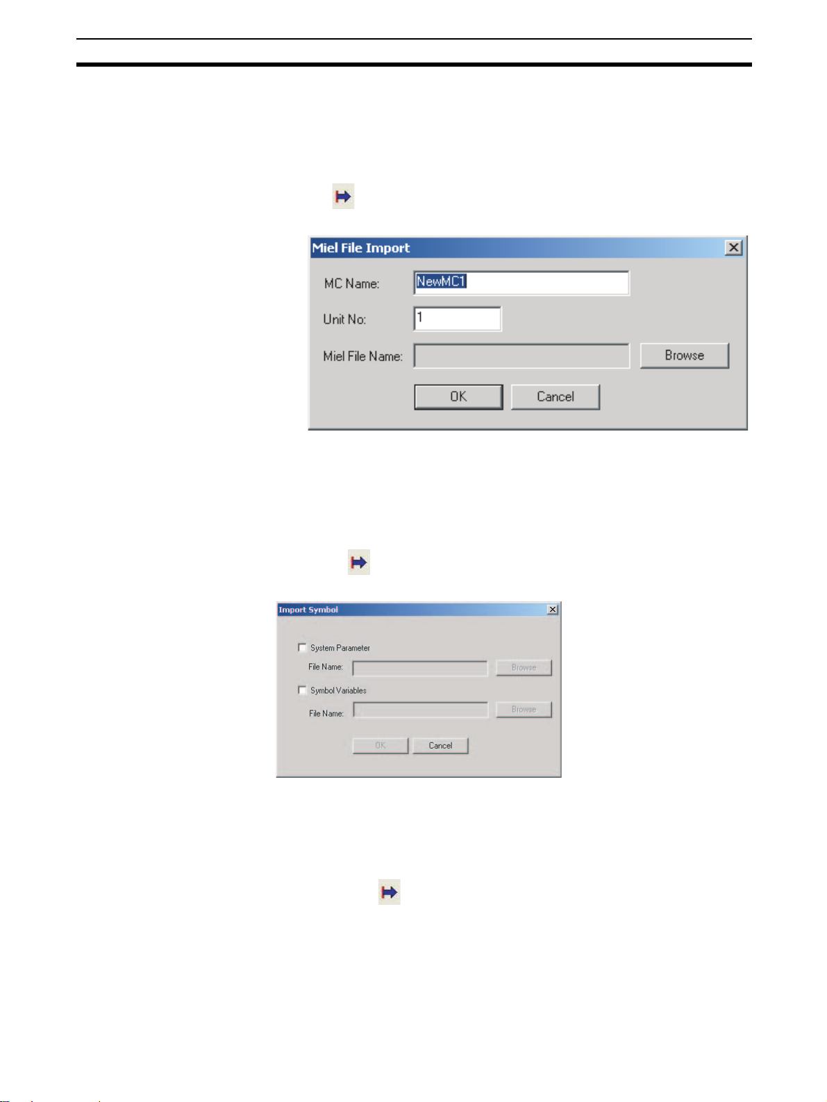
Importing Files Section 6-3
6-3 Importing Files
MC Miel for MCH Files This procedure imports a project file created as an MC Miel for MCH file (*.mil
filename extension).
1,2,3... 1. Select the PLC icon in the project tree and either select File - Import or
click in the toolbar. It is also possible to right-click the PLC icon and
select Import from Miel from the pop-up menu.
2. Enter the MC name, unit number, and Miel file name, then click the OK Button.
Symbol Files This procedure imports a system parameter or variable file under the Symbol
Icon (*.csv filename extension).
1,2,3... 1. Select the Symbol Icon in the project tree and either select File - Import
or click in the toolbar. It is also possible to right-click the Symbol Icon
and select Import from the pop-up menu.
2. Select the target system parameter or variable to be imported, enter or select the file name, and click the OK Button.
Position Data Files This procedure imports a position data file (*.csv filename extension).
1,2,3... 1. Select the Position Data Icon in the project tree and either select File - Im-
port or click in the toolbar. It is also possible to right-click the Position
Data Icon and select Import from the pop-up menu.
45
Page 66

Importing Files Section 6-3
2. Enter the destination folder, file name, and file type, and then click the
Open Button.
Program Files This procedure imports a program file (*.txt filename extension).
1,2,3... 1. Select the Programs Icon or an individual program icon in the project tree
and either select File - Import or click in the toolbar. It is also possible
to right-click the Programs Icon or the individual program icon and select
Import Program or Import from the pop-up menu.
Note When a file is imported to an individual program, the existing program will be
overwritten.
2. Enter the program name, program number, and select program, and then
click the OK Button.
Subprogram Files This procedure imports a subprogram file (*.txt filename extension).
1,2,3... 1. Select the Sub Programs Icon or an individual subprogram icon in the
project tree and either select File - Import or click in the toolbar. It is
also possible to right-click the Sub Programs Icon or the individual subprogram icon and select Import Sub Program or Import from the pop-up
menu.
46
Page 67

Importing Files Section 6-3
Note When a file is imported to an individual subprogram, the existing subprogram
will be overwritten.
2. Enter the subprogram name, subprogram number and select subprogram,
and then click the OK Button.
CAM Files This procedure imports a CAM file (*.csv filename extension).
1,2,3... 1. Select the CAM Icon or an individual CAM table icon in the project tree and
either select File - Import or click in the toolbar. It is also possible to
right-click the CAM Icon or the individual CAM table icon and select Import
CAM or Import from the pop-up menu.
Note When a file is imported to an individual CAM table, the existing CAM table will
be overwritten.
2. Enter the CAM name, CAM table number, and CAM table file, and then
click OK Button.
47
Page 68

Exporting File Section 6-4
6-4 Exporting File
Symbol File This procedure exports a symbol file (*.csv filename extension) containing the
system parameters and variables.
1,2,3... 1. Select the Symbol Icon in the project tree and either select File - Export
or click in the toolbar. It is also possible to right-click the Symbol Icon
and select Export from the pop-up menu.
2. Select the System Parameter and Symbol Variables Options, input the file
names (or click the Browse Button and select the file), and then click the
OK Button.
Position Data Files This procedure exports a position data file (*.csv filename extension).
1,2,3... 1. Select the Position Data Icon in the project tree and either select File - Ex-
port or click in the toolbar. It is also possible to right-click the Position
Data Icon and select Export from the pop-up menu.
2. Enter the destination folder, file name, and file type, and then click the Save
Button.
Program Files This procedure exports a program file (*.txt filename extension).
1,2,3... 1. Select an individual program icon in the project tree and either select File
48
- Export or click in the toolbar. It is also possible to right-click the in-
dividual program icon and select Export from the pop-up menu.
Page 69

Exporting File Section 6-4
2. Enter the destination folder, file name, and file type, and then click the Save
Button.
Subprogram Files This procedure exports a subprogram file (*.txt filename extension).
1,2,3... 1. Select an individual subprogram icon in the project tree and either select
File - Export or click in the toolbar. It is also possible to right-click the
individual subprogram icon and select Export from the pop-up menu.
Multiple Program/
Subprogram Files
2. Enter the destination folder, file name, and file type, and then click the Save
Button.
This procedure exports selected multiple program/subprogram files at the
same time (*.txt filename extension).
1,2,3... 1. Select the Motion programs, Programs, or Sub Programs Icon in the
project tree and either select File - Export or click in the tool bar. It is
also possible to right-click one of the above icons and select Export from
the pop-up menu.
49
Page 70

Exporting File Section 6-4
2. Select the programs and subprograms to be exported, select the destination folder, and then click the Export Button.
CAM Data Files This procedure exports a CAM data file (*.csv filename extension).
1,2,3... 1. Select an CAM table icon in the project tree and either select File - Export
or click in the toolbar. It is also possible to right-click the CAM table
icon and select Export from the pop-up menu.
50
Page 71

Exporting File Section 6-4
2. Enter the destination folder, file name, and file type, and then click the Save
Button.
51
Page 72

Exporting File Section 6-4
52
Page 73

SECTION 7
Transferring and Comparing Data
This section describes the operations used to transfer or compare data between the personal computer and Motion Control
Unit/Servo Driver, and to write data transferred to the Motion Control Unit to the Motion Control Unit's flash memory.
Note Be sure that the personal computer is connected to the PLC via a connecting cable and that online
communications are established before transferring data, comparing data, or writing data to flash
memory.
7-1 Initial Settings for Online Connection . . . . . . . . . . . . . . . . . . . . . . . . . . . . . . 54
7-2 Setting/Changing Communications Specifications. . . . . . . . . . . . . . . . . . . . . 54
7-3 Transferring, Comparing, and Saving Data . . . . . . . . . . . . . . . . . . . . . . . . . . 56
53
Page 74

Initial Settings for Online Connection Section 7-1
7-1 Initial Settings for Online Connection
Initial Settings for the CPU Unit and MC Unit
1,2,3... 1. Set the MC Unit’s unit number (using the rotary switch on the front panel)
2. Set the DIP switch on the CPU Unit or the Controller Section of the NSJ
Controller.
a. For Communications via Toolbus:
• When using the peripheral port, set SW4 to OFF, or set SW4 to ON
and make appropriate setting of PLC Setup (set Programming Console Address 144 to 0400 Hex).
• When using the RS-232C port, set SW5 to ON, or set SW5 to OFF and
make appropriate setting of PLC Setup (set Programming Console Address 160 to 0400 Hex).
b. For Communications via SYSMAC WAY (Host Link):
• When using the peripheral port, set SW4 to ON, or set SW4 to OFF
and make appropriate setting of PLC Setup. (Set Programming Console Address 144 to its default, 0000 Hex. If the default setting has not
been changed, leave the setting as it is.)
• When using the RS-232C port, set SW5 to OFF, or set SW5 to ON and
make appropriate setting of PLC Setup. (Set Programming Console
Address 160 to its default, 0000 Hex. If the default setting has not been
changed, leave the setting as it is.)
3. Create the I/O tables (using the CX-Programmer or a Programming Console).
7-2 Setting/Changing Communications Specifications
Communications Settings
1,2,3... 1. Right-click the PLC icon in the project tree and select Properties from the
pop-up menu. Select the Target PLC Setting on the PLC Properties Dialog
Box. The following dialog box will be displayed. Set the Device Type to be
connected to the PLC.
54
2. Set the Network Type.
Click the Network Type Drop-down List to display the list and select the de-
sired communications method.
Page 75

Setting/Changing Communications Specifications Section 7-2
3. Make the network settings
To check or change the network settings, click the Settings Button in the
Network Type Area.
a. Make settings in the Network Tab Page.
Connecting to the
PLC
b. Make settings in the Driver Tab Page.
Select Online - Work Online or click in the toolbar. It is also possible to
right-click the PLC icon in the project tree and select Work Online from the
pop-up menu.
Note When transferring driver parameters, the transfer may be stopped with the fol-
lowing message: “Error (36355) Communications to the device could not be
established or the connection has been broken. Check the communication
55
Page 76

Transferring, Comparing, and Saving Data Section 7-3
settings and connection method to the device.”
Open the PLC property to increase the response monitoring time in the PLC
Setup.
7-3 Transferring, Comparing, and Saving Data
Transferring to the MC Unit
1,2,3... 1. Select the MC Unit icon in the project tree and either select Online - Trans-
fer - To MC or click in the toolbar. It is also possible to right-click the
MC Unit icon in the project tree and select Transfer - To MC from the pop-
up menu.
56
2. Select the data to be transferred and then click the OK Button.
Page 77

Transferring, Comparing, and Saving Data Section 7-3
3. If the Write to Flash Memory Option is selected, the transferred data will
be saved in flash memory. The transfer will start when the OK Button is
clicked. The progress of the transfer will be displayed, as shown in the following diagram.
Transferring from the MC Unit
1,2,3... 1. Select the MC Unit icon in the project tree and either select Online - Trans-
fer - From MC or click in the toolbar. It is also possible to right-click the
MC Unit icon in the project tree and select Transfer - From MC from the
pop-up menu.
57
Page 78

Transferring, Comparing, and Saving Data Section 7-3
2. Select the data to be transferred and click the OK Button. The progress of
the transfer will be displayed, as shown in the following diagram.
Comparing Data with the MC Unit
1,2,3... 1. Select the MC Unit icon in the project tree and either select Online - Trans-
fer - Compare or click in the toolbar. It is also possible to right-click the
MC Unit icon in the project tree and select Transfer - Compare from the
pop-up menu.
58
2. Select the data to be compared and then click OK Button.
Page 79

Transferring, Comparing, and Saving Data Section 7-3
3. When the transfer from the MC Unit is completed, the Compare MC Window will be displayed showing the comparison results.
4. Double-click Position Data, Programs, Sub Programs, or Cam data. The
following window will be displayed.
5. Click the Overview Button to display the Overview Window.
6. Select File - Save as to save the overview or detail view of the results of
comparing programs.
59
Page 80

Transferring, Comparing, and Saving Data Section 7-3
Writing Data to Flash
Memory
!Caution Always backup the data in the flash memory after downloading the program,
parameter data, position data, or CAM data to the MC Unit. Otherwise, the
original data (before the transfer) will be restored the next time that the power
is turned ON, which may cause unexpected operation.
1,2,3... 1. Select the MC Unit icon in the project tree and either select Online - Write
To Fla sh or click in the toolbar. It is also possible to right-click the MC
Unit icon in the project tree and select Write To Flash from the pop-up
menu.
2. Select the data to be saved in the Data Type Options and click the Write
Note If an error occurs while data is being written to the flash memory, the data may
not be written to the flash memory successfully. In this case, write the data to
the flash memory again after resetting the error.
Displaying Unit Information
1,2,3... 1. Select Online - Unit Information.
2. The MC Unit’s model and version information will be displayed.
Button.
60
Page 81

Transferring, Comparing, and Saving Data Section 7-3
Initializing Memory
1,2,3... 1. Select the MC Unit icon in the project tree and either select Online - Clear
Memory or click in the toolbar. It is also possible to right-click the MC
Unit icon in the project tree and select Clear Memory from the pop-up
menu.
2. Select the data to be initialized and click the OK Button.
Batch Transfer (Computer to MC Unit)
1,2,3... 1. Select the PLC icon in the project tree and either select Online - Batch
Transfer - To All MC or click in the toolbar. It is also possible to right-
click the PLC icon in the project tree and select Batch Transfer - To MC
from the pop-up menu.
2. Select the destination MC Unit in the Select MC Drop-down List. Select the
data to be transferred and click the OK Button.
Batch Transfer (MC Unit to Computer)
1,2,3... 1. Select the PLC icon in the project tree and either select Online - Batch
Transfer - From All MC or click in the toolbar. It is also possible to
right-click the PLC icon in the project tree and select Batch Transfer From MC from the pop-up menu.
2. Select the source MC Unit in the Select MC Drop-down List. Select the
data to be transferred and click the OK Button.
61
Page 82

Transferring, Comparing, and Saving Data Section 7-3
Range Transfer (Computer to MC Unit)
1,2,3... 1. Right-click in the Edit Parameters Window or Edit Position Data Window
and select Range Transfer - To MC from the pop-up menu.
2. The data of the selected Value will be transferred to the MC Unit.
Range Transfer (MC Unit to Computer)
1,2,3... 1. Right-click in the Edit Parameters Window or Edit Position Data Window
and select Range Transfer - From MC from the pop-up menu.
2. The data of the selected Value will be transferred from the MC Unit.
62
Page 83

SECTION 8
Monitoring
This section provides information on monitoring the MC Units. The error status, axis's present position, and variable values
are displayed in the Monitor Windows.
Note Be sure that the computer and PLC are connected with the connection cable and the communications
between them are established before starting monitoring operations.
8-1 Status Monitor. . . . . . . . . . . . . . . . . . . . . . . . . . . . . . . . . . . . . . . . . . . . . . . . . 64
8-2 General Watch Window . . . . . . . . . . . . . . . . . . . . . . . . . . . . . . . . . . . . . . . . . 64
63
Page 84

Status Monitor Section 8-1
8-1 Status Monitor
Use the Status Monitor to monitor MC Unit errors, the present position of each
axis, and the program number in progress.
Starting the Status
Click in the toolbar.
Monitor
If the CX-Motion-MCH is connected online, monitoring will start automatically;
if the CX-Motion-MCH is offline, monitoring will stop.
8-2 General Watch Window
The General Watch Window can be used to check and change variable values
(excluding system variables).
Starting the General
Watch Window
Click in the toolbar.
If the CX-Motion-MCH is connected online, monitoring will start automatically;
if the CX-Motion-MCH is offline, monitoring will stop.
To check a variable, select Insert from the Context Menu and register the variable.
To change a variable’s value, change the value directly in the variable’s Value
column and press the Enter Key to confirm the change.
The variables registered in the General Watch Window can also be referenced again by saving the project.
64
Page 85

SECTION 9
Operation
This section describes various operations on the axes of the MC Unit, including test run operations and program debugging.
Note Operation from Support Tool is supported for MC Units with unit version 3.0 or later.
9-1 Switching to Monitor Mode . . . . . . . . . . . . . . . . . . . . . . . . . . . . . . . . . . . . . . 66
9-1-1 Starting Monitor Mode . . . . . . . . . . . . . . . . . . . . . . . . . . . . . . . . . . . 66
9-1-2 Ending Monitor Mode . . . . . . . . . . . . . . . . . . . . . . . . . . . . . . . . . . . 67
9-2 Test Run . . . . . . . . . . . . . . . . . . . . . . . . . . . . . . . . . . . . . . . . . . . . . . . . . . . . . 67
9-2-1 Executing a Test Run . . . . . . . . . . . . . . . . . . . . . . . . . . . . . . . . . . . . 67
9-2-2 Test Run Window . . . . . . . . . . . . . . . . . . . . . . . . . . . . . . . . . . . . . . . 68
9-3 Debugging the Program . . . . . . . . . . . . . . . . . . . . . . . . . . . . . . . . . . . . . . . . . 69
9-3-1 Setting Break Points . . . . . . . . . . . . . . . . . . . . . . . . . . . . . . . . . . . . . 69
9-3-2 Debugging the Program . . . . . . . . . . . . . . . . . . . . . . . . . . . . . . . . . . 70
65
Page 86

Switching to Monitor Mode Section 9-1
9-1 Switching to Monitor Mode
9-1-1 Starting Monitor Mode
1,2,3... 1. Select a PLC icon in the project tree and select Online - Work Online, or
right-click a PLC icon and select Work Online from the pop-up menu. It is
also possible to click in the toolbar. The CX-Motion-MCH will be connected to the PLC.
2. Select the MC Unit in the project tree, and then select Online - Monitor
Mode or click in the toolbar. The following warning dialog box will be
displayed. Read the contents of the warning carefully. Click the OK Button
only after confirming safety.
3. The CX-Motion-MCH will switch to Monitor Mode, and the following Test
Run Window and Stop Axes Button will be displayed. will be displayed
in the toolbar.
The Stop Axes Button can be used in Monitor Mode and will come to the
front of the displayed window. All axes will decelerate to a stop if the Stop
Axes Button is clicked.
66
Page 87

Test R u n Section 9-2
Note The Status Monitor Window will not be displayed in Monitor Mode. Also, the
MC Unit cannot be controlled from the ladder program in Monitor Mode.
9-1-2 Ending Monitor Mode
1,2,3... 1. Select Online - Monitor Mode or click in the toolbar.
2. Monitor Mode will be ended, and the CX-Motion-MCH will display in
the toolbar.
9-2 Test Run
9-2-1 Executing a Test Run
1,2,3... 1. Select the axis for which to execute a test run in the Test Run Window.
2. Click to lock the selected axis.
3. To use an override, select the Axis Override Option and enter the override
set value. Click the Set Button to write the set value to the MC Unit.
4. Click the JOG, STEP, or Origin Buttons. The axis will be operated.
Note (1) Clicking any of the operation buttons will operate the motor at the desig-
nated speed. Execute the operation only after confirming safety.
(2) The operation on the personal computer may not stop the motor. Provide
an emergency stop device externally to enable stopping the motor immediately at any time.
67
Page 88

Test R u n Section 9-2
9-2-2 Test Run Window
Tes t R un
Axis No. Sets the axis to operate.
Position Displays the current position of the axis.
Busy Displays the operating status.
Servo Lock Servo Locks/unlocks the axis.
Lock/Unlock
Multiple
Override Axis Override Sets the override value.
Set Sets the override in the MC Unit.
STEP + Steps the axis in the positive direction.
− Steps the axis in the negative direction.
JOG + Jogs the axis in the positive direction.
− Jogs the axis in the negative direction.
Origin Search Searches for the origin.
Origin Return Returns the axis to the origin.
Forced Origin Force the current position to the origin.
Task Error Display the error code occurred in Task. Click
Axis Error Displays any error code for any error that has
Unit Error Displays any error code for any error that has
Clear All Errors Resets all errors that have occurred in the task,
Displays a dialog to lock/unlock multiple axes.
Range: 0.00 to 327.67%
the Reset Button to reset the error.
occurred for the axis. Click the Reset Button to
reset the error.
occurred in the MC Unit. Click the Reset Button
to reset the error.
axis, and unit.
68
Page 89

Debugging the Program Section 9-3
Absolute Origin
Setting
Teaching Type Sets either a Feedback Present Position or
External I/O Status
ABS Offset Displays the value of the Absolute Origin Offset
set in the Axis Parameters of the MC Unit.
Set Sets the absolute origin.
Command Present Position.
Address Sets the first address in which to store data
(position data number).
Range: 0 to 10239
Teach Executes teaching.
After execution, the address will be incremented
automatically.
9-3 Debugging the Program
The CX-Motion-MCH can be used to debug the motion program in an MC
Unit.
Before switching to Monitor Mode, click To MC or From MC to transfer the
motion program between the MC Unit and CX-Motion-MCH so that both the
MC Unit and CX-Motion-MCH have the same program.
Note Debugging motion program is supported for MC Units with unit version 3.0 or
later.
9-3-1 Setting Break Points
1,2,3... 1. Display the program to debug.
2. Move the cursor to the step to set the break point, and click . A break
point mark will be displayed.
3. Click again, the break point will be removed.
69
Page 90

Debugging the Program Section 9-3
9-3-2 Debugging the Program
1,2,3... 1. Display the program.
2. Servolock the axis to be used if the program operates the axis.
3. In the toolbar, select the number of the task to debug.
4. Click in the toolbar, the MC Unit will execute the program. Program execution will stop at the first break point.
5. Set variables in the General Watch Window as required.
6. Click in the toolbar to debug the program again from the first break
point. Click in the toolbar to debug the program one step at a time.
70
Note In the following case, program execution will not stop at a breakpoint and will
continue to the next break point.
• The first break point is skipped using the IF function.
When step 0004 is false, step 0007 would be executed next after step 0004. A
break point is set for step 0007, so program execution would stop at the step
that was executed immediately before step 0007. In this example, that would
be step 0004, i.e., program execution would stop immediately after executing
the IF statement in step 0004.
Program execution also may not stop at a break point set for the WHILE,
FOR, PARALLEL, and SWITCH control commands.
Page 91

Debugging the Program Section 9-3
Note (1) Clicking any of the operation buttons will operate the motor at the desig-
nated speed. Execute the operation only after confirming safety.
(2) The operation on the personal computer may not stop the motor. Provide
an emergency stop device externally to enable stopping the motor immediately at any time.
71
Page 92

Debugging the Program Section 9-3
72
Page 93

This section describes the data trace function.
Note Data traces are supported for MC Units with unit version 3.0 or later.
10-1 Data Traces . . . . . . . . . . . . . . . . . . . . . . . . . . . . . . . . . . . . . . . . . . . . . . . . . . . 74
10-1-1 Executing a Data Trace. . . . . . . . . . . . . . . . . . . . . . . . . . . . . . . . . . . 74
10-1-2 Changing the Graph Display . . . . . . . . . . . . . . . . . . . . . . . . . . . . . . 75
SECTION 10
Data Traces
73
Page 94

Data Traces Section 10-1
10-1 Data Traces
10-1-1 Executing a Data Trace
1,2,3... 1. Select the PLC icon in the project tree and select Online - Work On line,
or right-click the PLC icon and select Work Online from the pop-up menu.
It is also possible to click in the toolbar. The CX-Motion-MCH will be
connected to the PLC.
2. Select the MC Unit icon in the project tree, and then select Online - Data
Trace or click in the toolbar. The Data Trace Window will be displayed.
74
3. Click in the Data Trace Window. The Data Trace Configuration dialog
box will be displayed.
Page 95

Data Traces Section 10-1
4. Set the trigger conditions, trace objects, and number of samplings.
5. Click the Transfer [PC to MC] Button to write the set values to the MC Unit.
6. Click the OK Button to close the Data Trace Configuration Dialog Box.
7. Click in the Data Trace Window. The MC Unit will execute the data
trace.
8. The trigger condition is activated, and the data trace is completed. The MC
Unit will transfer the results of the data trace to the CX-Motion-MCH automatically and display them graphically.
10-1-2 Changing the Graph Display
1,2,3... 1. Select in the legend to display the required items.
2. Select the data of the item to change.
3. Change the vertical scale using in the Graph Tools Window.
4. Change the displayed position using .
5. Select to display the value at the cursor position.
6. Select to display the difference between two points.
7. Click in the Data Trace Window to save the data to a CSV file.
75
Page 96

Data Traces Section 10-1
76
Page 97

SECTION 11
Backup and Restore
This section describes the operations used to back up data from MC Units and restore data to MC Units.
Note • Be sure that the personal computer is connected to the PLC via a Connecting Cable and that online
communications are established before backing up and restoring data.
• Backing up and restoring data is supported for MC Units with unit version 3.1 or later.
11-1 Backup from MC . . . . . . . . . . . . . . . . . . . . . . . . . . . . . . . . . . . . . . . . . . . . . . 78
11-2 Restoring to MC . . . . . . . . . . . . . . . . . . . . . . . . . . . . . . . . . . . . . . . . . . . . . . . 78
11-3 Verifying Backup File with MC Unit . . . . . . . . . . . . . . . . . . . . . . . . . . . . . . . 79
77
Page 98

Backup from MC Section 11-1
11-1 Backup from MC
Use the following procedure to backup an MC Unit on the CX-Motion-MCH.
1,2,3... 1. Select Online - Backup and Restore - Backup from MC in online mode.
The following window will be displayed.
2. After entering or selecting the destination folder, file name and file type,
click the Save Button. Use the default file type (*.bkh), because the MC
Unit data is being saved in a CX-Motion-MCH backup file.
11-2 Restoring to MC
Use the following procedure to restore a backup file to an MC Unit.
1,2,3... 1. Select Online - Backup and Restore - Restore to MC in online mode.
2. Click the OK Button to display the following window.
The following message will be displayed.
78
Page 99

Verifying Backup File with MC Unit Section 11-3
3. Enter or select the folder to be looked in, the file name, and the file type,
and then click the Open Button. The following message will be displayed
after restoring backup data is done.
4. Click the Yes Button to start verifying.
11-3 Verifying Backup File with MC Unit
Use the following procedure to verify a backup file with an MC Unit.
1,2,3... 1. Select Online - Backup and Restore - Verify Backup file with MC Unit
in online mode. The following window will be displayed.
2. Enter or select the destination folder, file name, and file type, and then click
the Open Button. Verifying will start. A message will be displayed to tell if
the data is identical.
79
Page 100

Verifying Backup File with MC Unit Section 11-3
80
 Loading...