

Page 1

Cat. No. W464-E1-06
SYSMAC
CXONE-AL_C-V4/
CXONE-AL_D-V4
CS/CJ/CP/NSJ Series
CX-Integrator Ver. 2
OPERATION MANUAL
Page 2

Page 3

CXONE-AL@@C-V4/
CXONE-AL@@D-V4
CX-Integrator Ver. 2.@
Operation Manual
Revised December 2009
Page 4

iv
Page 5

f
Notice:
OMRON products are manufactured for use according to proper procedures by a qualified operator
and only for the purposes described in this manual.
The following conventions are used to indicate and classify precautions in this manual. Always heed
the information provided with them. Failure to heed precautions can result in injury to people or
damage to property.
!DANGER Indicates an imminently hazardous situation which, if not avoided, will result in death or
serious injury. Additionally, there may be severe property damage.
!WARNING Indicates a potentially hazardous situation which, if not avoided, could result in death or
serious injury. Additionally, there may be severe property damage.
!Caution Indicates a potentially hazardous situation which, if not avoided, may result in minor or
moderate injury, or property damage.
OMRON Product References
All OMRON products are capitalized in this manual. The word “Unit” is also capitalized when it refers
to an OMRON product, regardless of whether or not it appears in the proper name of the product.
The abbreviation “Ch,” which appears in some displays and on some OMRON products, often means
“word” and is abbreviated “Wd” in documentation in this sense.
The abbreviation “PLC” means Programmable Controller. “PC” is used, however, in some
Programming Device displays to mean Programmable Controller.
Visual Aids
The following headings appear in the left column of the manual to help you locate different types of
information.
Note Indicates information of particular interest for efficient and convenient
operation of the product.
1,2,3... 1. Indicates lists of one sort or another, such as procedures, checklists, etc.
OMRON, 2008
All rights reserved. No part of this publication may be reproduced, stored in a retrieval system, or transmitted, in any form,
or by any means, mechanical, electronic, photocopying, recording, or otherwise, without the prior written permission o
OMRON.
No patent liability is assumed with respect to the use of the information contained herein. Moreover, because OMRON is
constantly striving to improve its high-quality products, the information contained in this manual is subject to change
without notice. Every precaution has been taken in the preparation of this manual. Nevertheless, OMRON assumes no
responsibility for errors or omissions. Neither is any liability assumed for damages resulting from the use of the information
contained in this publication.
v
Page 6

vi
Page 7

TABLE OF CONTENTS
PRECAUTIONS
1 Intended Audience ..............................................................................................................xx
2 Safety Precautions.............................................................................................................. xx
3 Application Precautions .................................................................................................... xxii
4 Operating Environment Precautions................................................................................. xxv
5 Guide to Version Upgrade ............................................................................................... xxvi
Section 1 Overview
1-1 The CX-Integrator ............................................................................................................. 1-2
1-1-1 Overview .............................................................................................................. 1-2
1-1-2 Functions According to Network .......................................................................... 1-4
1-1-3 Connecting to the Relay PLC .............................................................................. 1-4
1-1-4 Accessible Network.............................................................................................. 1-5
1-1-5 Communicating Across Network Layers.............................................................. 1-7
1-1-6 Starting Other Applications .................................................................................. 1-7
1-2 Specifications.................................................................................................................... 1-8
1-2-1 CX-Integrator Specifications ................................................................................ 1-8
1-2-2 Files Created by the CX-Integrator .................................................................... 1-12
1-3 Installation....................................................................................................................... 1-14
1-4 PLC Connecting Cables.................................................................................................. 1-15
1-4-1 Direct Serial Connections to a PLC ................................................................... 1-15
1-4-2 Connecting CJ-series CJ2 CPU Units, CP-series PLCs and
NSJ-series Controllers Using Commercially Available USB Cable ................... 1-21
1-5 Window Descriptions ...................................................................................................... 1-34
1-5-1 Starting Methods................................................................................................ 1-34
1-5-2 Main Window ..................................................................................................... 1-34
1-6 Menus ............................................................................................................................. 1-49
1-6-1 Menus 1-49
1-6-2 Pop-up Menus.................................................................................................... 1-54
1-6-3 Toolbars ............................................................................................................. 1-62
Section 2 Basic Operations
2-1 Basic Procedures.............................................................................................................. 2-2
2-2 Connecting Online to the Relay PLC .............................................................................. 2-10
2-2-1 Overview ............................................................................................................ 2-10
2-2-2 Procedures......................................................................................................... 2-11
2-2-3 CPU Unit Troubleshooting ................................................................................. 2-22
2-3 Uploading Network Configurations and Checking for Communications Unit Errors....... 2-23
2-3-1 Overview ............................................................................................................ 2-23
2-3-2 Procedure .......................................................................................................... 2-23
2-3-3 Checking and Correcting Communications Unit Errors ..................................... 2-31
2-4 Switching the Target PLC ............................................................................................... 2-33
2-4-1 Overview ............................................................................................................ 2-33
2-4-2 Procedure .......................................................................................................... 2-33
vii
Page 8

Creating Virtual Network Configurations Offline ............................................................. 2-35
2-5
2-5-1 Overview ............................................................................................................ 2-35
2-5-2 Procedure........................................................................................................... 2-35
2-5-3 Changing Node Addresses ................................................................................ 2-45
2-5-4 Editing Components (Devices) .......................................................................... 2-46
2-6 Manipulating Component Parameters ............................................................................ 2-49
2-6-1 Overview ............................................................................................................ 2-49
2-6-2 Procedure........................................................................................................... 2-50
2-7 Uploading, Downloading, and Comparing Network Parameters .................................... 2-54
2-7-1 Overview ............................................................................................................ 2-54
2-7-2 Procedure........................................................................................................... 2-54
2-8 Comparing Network Configurations ................................................................................ 2-55
2-8-1 Overview ............................................................................................................ 2-55
2-8-2 Procedure........................................................................................................... 2-55
2-9 File Operations................................................................................................................ 2-56
2-9-1 Overview ............................................................................................................ 2-56
2-9-2 Procedures......................................................................................................... 2-57
2-10 Target PLC Online Operations........................................................................................ 2-60
2-10-1 Overview ............................................................................................................ 2-60
2-10-2 Procedure........................................................................................................... 2-60
2-11 Starting Specified Applications ....................................................................................... 2-62
2-11-1 Overview ............................................................................................................ 2-62
2-11-2 Procedure........................................................................................................... 2-62
2-12 Printing ........................................................................................................................... 2-63
Section 3 Routing Tables
3-1 Routing Table Overview.................................................................................................... 3-2
3-1-1 Definition of Routing Tables................................................................................. 3-2
3-1-2 Network Conditions That Require Routing Tables............................................... 3-4
3-1-3 Routing Table Setting Methods............................................................................ 3-5
3-1-4 Routing Table File Types Supported by the CX-Integrator.................................. 3-6
3-1-5 Transferring the Routing Tables .......................................................................... 3-6
3-1-6 Operating Procedures Prior to Routing Table Transfer ....................................... 3-7
3-2 Setting the Routing Tables.............................................................................................. 3-11
3-2-1 Routing Table Setting Example ......................................................................... 3-11
3-2-2 Creating the FINS Local Routing Tables ........................................................... 3-12
3-2-3 Setting the Gateway Counter............................................................................. 3-20
3-2-4 Checking Routing Tables for Errors................................................................... 3-23
3-2-5 Transferring Routing Tables to a Directly Connected PLC................................ 3-24
3-2-6 Saving Routing Tables....................................................................................... 3-26
3-2-7 Reading Routing Tables .................................................................................... 3-26
3-2-8 Verifying Routing Tables.................................................................................... 3-26
3-2-9 Printing Routing Tables...................................................................................... 3-27
3-2-10 Transferring Routing Tables to a Network PLC through
a Direct Serial Connection ................................................................................. 3-28
viii
Page 9

Maintenance after Network Configuration ...................................................................... 3-32
3-3
3-3-1 FINS Network Routing Tables ........................................................................... 3-32
3-3-2 Editing the FINS Local Network Tables ............................................................. 3-32
Section 4 Data Links for Controller Link and SYSMAC LINK
4-1 Overview ........................................................................................................................... 4-2
4-1-1 What Are Data Links? .......................................................................................... 4-2
4-1-2 Overview of Procedure by Data Link Setting Method .......................................... 4-3
4-2 User Interface Overview ................................................................................................... 4-4
4-2-1 Starting the Data Link Component....................................................................... 4-4
4-2-2 Datalink Component ............................................................................................ 4-4
4-3 Manually Setting Data Links ............................................................................................. 4-8
4-3-1 Procedure through Data Link Startup .................................................................. 4-8
4-3-2 Creating Data Link Tables ................................................................................... 4-9
4-3-3 System Configuration Example ......................................................................... 4-11
4-3-4 Creating Data Link Tables Offline...................................................................... 4-12
4-3-5 Procedure Using Setup Example....................................................................... 4-23
4-3-6 Checking Data Link Tables ................................................................................ 4-25
4-3-7 Printing Data Link Tables................................................................................... 4-25
4-3-8 Saving Data Link Tables .................................................................................... 4-26
4-3-9 Creating, Reading, and Writing CSV Files (Saving) .......................................... 4-26
4-3-10 Reading and Data Link Tables .......................................................................... 4-32
4-3-11 Transferring the Data Link Table ....................................................................... 4-34
4-3-12 Starting and Stopping Data Links (Including Status Displays) .......................... 4-41
4-4 Automatically Set Data Links .......................................................................................... 4-43
4-4-1 Procedure Through Data Link Startup ............................................................... 4-43
4-4-2 Controller Link Automatic Setup ........................................................................ 4-44
4-4-3 SYSMAC LINK Automatic Setup ....................................................................... 4-49
4-4-4 Transferring Automatic Data Link Setup Parameters to the Startup Node........ 4-50
4-4-5 Monitoring Data Link Status............................................................................... 4-52
Section 5 Ethernet
5-1 Broadcast Node Search.................................................................................................... 5-2
5-1-1 Overview .............................................................................................................. 5-2
5-1-2 Procedure ............................................................................................................ 5-2
5-2 Ping Test........................................................................................................................... 5-4
5-2-1 Overview .............................................................................................................. 5-4
5-2-2 Procedure ............................................................................................................ 5-4
Section 6 DeviceNet
6-1 DeviceNet Setting Procedures.......................................................................................... 6-2
6-1-1 Designing Networks Offline.................................................................................. 6-2
6-1-2 Downloading Saved Parameters ......................................................................... 6-2
6-1-3 Saving the Parameters for the Entire Existing Network....................................... 6-3
6-2 Setting Slave Parameters ................................................................................................. 6-4
6-2-1 Editing Slave Parameters .................................................................................... 6-4
6-2-2 Checking and Setting I/O Size ............................................................................. 6-6
ix
Page 10

Adding Slaves to the Master ............................................................................................. 6-8
6-3
6-3-1 Automatic I/O Area Allocation with Registration .................................................. 6-8
6-3-2 Adding Slaves .................................................................................................... 6-10
6-4 Setting Master Properties................................................................................................ 6-13
6-4-1 CS1W-DRM21(-V1) and CJ1W-DRM21 ............................................................ 6-13
6-4-2 CVM1-DRM21-V1 or C200HW-DRM21-V1 ....................................................... 6-14
6-5 Editing Master Parameters.............................................................................................. 6-15
6-6 Parameter Wizard ........................................................................................................... 6-16
6-7 Master Parameter Editing Details (Tab Descriptions)..................................................... 6-21
6-7-1 Edit Device Parameters on CS1W-DRM21(-V1)/CJ1W-DRM21 ....................... 6-22
6-7-2 Editing Device Parameters on CVM1-DRM21-V1 and C200HW-DRM21-V1 ... 6-24
6-7-3 Editing Device Parameters on 3G8F7-DRM21 DeviceNet PCI Board Scanner 6-26
6-7-4 Canceling Slave Registration with the Master ................................................... 6-28
6-7-5 Automatic Allocation with Registration............................................................... 6-28
6-8 Manual I/O Allocations .................................................................................................... 6-29
6-8-1 I/O Allocation Tab Page ..................................................................................... 6-29
6-8-2 Changing the First Address of Output/Input Block............................................. 6-30
6-8-3 Allocating I/O...................................................................................................... 6-32
6-8-4 Slave Information ............................................................................................... 6-35
6-9 Advanced Settings
(Connection, Communication Cycle Time, Slave Function Settings, Etc.) ..................... 6-36
6-9-1 Advanced Settings ............................................................................................. 6-36
6-9-2 Communication Cycle Time Settings ................................................................. 6-38
6-9-3 Setting Message Timers ....................................................................................6-39
6-9-4 Slave Function Settings ..................................................................................... 6-41
6-9-5 Setting/Canceling Explicit Message Communications....................................... 6-42
6-9-6 Starting Remote I/O Communications ............................................................... 6-42
6-10 Creating and Editing I/O Comments ............................................................................... 6-43
6-11 Displaying Device Properties .......................................................................................... 6-45
6-11-1 Property Dialog Box Common to All Devices .................................................... 6-45
6-11-2 I/O Information Inherent to Each Slave Device.................................................. 6-46
6-11-3 Information for Master ........................................................................................ 6-48
6-12 Downloading the Network Configuration/Device Parameters to Devices....................... 6-51
6-12-1 Downloading the Network Configuration............................................................ 6-51
6-12-2 Downloading Device Parameters....................................................................... 6-53
6-12-3 Resetting the Device .......................................................................................... 6-55
6-13 Uploading and Verifying Device Parameters .................................................................. 6-56
6-13-1 Uploading the Network Configuration ................................................................ 6-56
6-13-2 Uploading Device Parameters ........................................................................... 6-56
6-13-3 Verifying the Network Configuration .................................................................. 6-58
6-13-4 Verifying Device Parameters ............................................................................. 6-59
6-14 Monitoring Devices.......................................................................................................... 6-61
6-14-1 Setting Monitor Refresh Timer ........................................................................... 6-61
6-14-2 Monitoring Devices............................................................................................. 6-62
6-15 Using General-purpose Tools to Set Devices................................................................. 6-69
6-15-1 Setting Device Parameters with Class Instances .............................................. 6-69
x
Page 11

Optional Functions .......................................................................................................... 6-71
6-16
6-16-1 Installing Expansion Modules ............................................................................ 6-71
6-16-2 Adding Vendors and Device Types ................................................................... 6-71
Section 7 CompoNet
7-1 Overview ........................................................................................................................... 7-2
7-1-1 What Is CompoNet?............................................................................................. 7-2
7-2 Basic Procedures.............................................................................................................. 7-3
7-2-1 Basic Procedures................................................................................................. 7-3
7-2-2 Optional Settings.................................................................................................. 7-4
7-3 Uploading, Downloading, and Comparing Network Configurations.................................. 7-5
7-3-1 Upload the Network Configuration to the Computer............................................ 7-5
7-3-2 Comparing Network Configurations..................................................................... 7-6
7-4 Component Monitor .......................................................................................................... 7-7
7-4-1 Starting Monitoring............................................................................................... 7-7
7-4-2 Master Unit Monitor Window................................................................................ 7-8
7-5 Uploading, Downloading, and Comparing Component Parameters............................... 7-13
7-5-1 Uploading Component Parameters to a Computer ........................................... 7-13
7-5-2 Comparing Component Parameters .................................................................. 7-14
7-5-3 Downloading the Component Parameters to the Components ......................... 7-15
7-5-4 Resetting Component ........................................................................................ 7-17
7-6 Editing Master Unit Parameters ...................................................................................... 7-18
7-6-1 Master Unit Parameter Settings......................................................................... 7-18
7-6-2 Editing the Registration Table............................................................................ 7-23
7-6-3 Editing the Software Setting Table .................................................................... 7-26
7-7 Editing Slave Parameters ............................................................................................... 7-28
7-7-1 Setting Slave Parameters ................................................................................ 7-28
7-7-2 Checking the Slave I/O Size ............................................................................ 7-29
7-8 Other CompoNet Functions ............................................................................................ 7-30
7-8-1 Additional Functions........................................................................................... 7-30
7-8-2 Installing Expansion Modules ............................................................................ 7-31
Section 8 CompoWay/F
8-1 CompoWay/F System Configuration ................................................................................ 8-2
8-1-1 Overview .............................................................................................................. 8-2
8-2 CompoWay/F Slaves Connected to a PLC....................................................................... 8-3
8-2-1 Communications with CompoWay/F Slaves through a PLC ............................... 8-3
8-2-2 Setting the CompoWay/F Slave’s Parameters .................................................... 8-8
8-3 CompoWay/F Slaves Connected to a Computer............................................................ 8-10
8-3-1 Reading from Slaves Connected to the Computer ............................................ 8-10
Section 9 NT Links
9-1 NT Link Connection Auto-detect Function ........................................................................ 9-2
9-1-1 Overview .............................................................................................................. 9-2
9-1-2 Procedure ............................................................................................................ 9-2
xi
Page 12

Transferring Screen Data through the PLC ...................................................................... 9-6
9-2
9-2-1 Overview .............................................................................................................. 9-6
9-2-2 Procedure............................................................................................................. 9-6
Section 10 Network Testing
10-1 Controller Link Network Diagnostic Tool......................................................................... 10-2
10-1-1 Diagnostic Functions and Flowcharts ................................................................ 10-2
10-1-2 Diagnosing Network Status................................................................................ 10-5
10-1-3 Diagnosing Node Settings ............................................................................... 10-11
10-1-4 Diagnosing Disconnections.............................................................................. 10-14
10-1-5 Diagnosing Transmission Status ..................................................................... 10-17
10-1-6 Node Status ..................................................................................................... 10-18
10-1-7 Collecting Error Logs........................................................................................ 10-21
10-2 Echoback Test between Nodes .................................................................................... 10-22
10-2-1 Overview .......................................................................................................... 10-22
10-2-2 Start Methods ................................................................................................... 10-22
10-2-3 PLC Internode Echoback Test Dialog Box....................................................... 10-22
10-2-4 Executing an Echoback Test between Nodes ................................................. 10-23
10-3 Ethernet Ping Test ........................................................................................................10-25
10-3-1 Overview .......................................................................................................... 10-25
10-3-2 Start Methods ................................................................................................... 10-25
10-3-3 Ping Test Dialog Box........................................................................................ 10-25
10-3-4 Executing a Ping Test ......................................................................................10-26
Appendices
A-1 CPS File Management......................................................................................................A-2
A-1-1 Description of CPS Files ......................................................................................A-2
A-2 EDS File Management......................................................................................................A-5
A-2-1 Installing EDS Files ..............................................................................................A-5
A-2-2 Creating EDS Files............................................................................................... A-6
A-2-3 Deleting EDS Files ...............................................................................................A-7
A-2-4 Saving EDS Files .................................................................................................A-7
A-2-5 Searching EDS Files ............................................................................................A-8
A-2-6 Displaying EDS File Properties ............................................................................A-8
A-3 Precautions When Using Windows Vista or Windows 7 ................................................... A-9
Revision History
xii
Page 13

About this Manual:
This manual describes the installation and operation of CX-Integrator and includes the sections
described below.
Please read this manual carefully and be sure you understand the information provided before
attempting to use the CX-Integrator. Be sure to read the precautions provided in the following section.
Precautions provides general precautions for using the CX-Integrator.
Section 1 outlines the functions of the CX-Integrator and describes the menus and connecting to
networks.
Section 2 describes the basic operations required to use the CX-Integrator.
Section 3 describes how to set routing tables.
Section 4 describes how to set data links for Controller Link and SYSMAC LINK Networks.
Section 5 describes how to use the diagnostic tools for Controller Link Networks.
Section 6 describes settings and operations unique to DeviceNet Networks, including registering
slaves in the master, allocating I/O, monitoring devices, etc.
Section 7 describes the basic use of and how to set parameters for CompoNet Networks.
Section 8 describes settings and operations unique to CompoWay/F Networks.
Section 9 settings and operations unique to NT Links.
Section 10 describes operations for testing networks using the Controller Link Network Diagnostic
Tool, echoback tests between nodes, and Ethernet ping tests.
The Appendix describes CPS files for Ethernet, Controller Link, CompoWay/F, and NT Link
Networks and EDS files for DeviceNet Networks.
!WARNING Failure to read and understand the information provided in this manual may result in
personal injury or death, damage to the product, or product failure. Please read each
section in its entirety and be sure you understand the information provided in the section
and related sections before attempting any of the procedures or operations given.
xiii
Page 14

Manuals Related to the CX-Integrator
Cat No. Models Name Description
W464
(this manual)
W463
W446 WS02-CXPC1-V9
W447 WS02-CXPC1-V9
W469 WS02-CXPC1-V9
CXONE-AL@@C-V4
CXONE-AL@@D-V4
CXONE-AL@@C-V4
CXONE-AL@@D-V4
CX-Integrator Operation
Manual
CX-One Setup Manual Describes installation and provides an
CX-Programmer Ver. 9.@
Operation Manual
CX-Programmer Ver. 9.@
Operation Manual:
Function Blocks and
Structured Text
CX-Programmer Ver. 9.@
Operation Manual: SFC
Describes CX-Integrator operating
methods, e.g., for setting up and
monitoring networks.
overview of the CX-One FA Integrated
Tool Package.
Describes CX-Programmer operations
except those related to function blocks.
Describes function block functions and
programming in structured text language.
For basic CX-Programmer operations,
refer to the CX-Programmer Operation
Manual (W446).
Describes the SFC programming
functions. For basic CX-Programmer
operations, refer to the CX-Programmer
Operation Manual (W446).
Manuals Related to DeviceNet
Cat No. Models Name Description
W267 --- DeviceNet Operation
Manual
W380 CS1W-DRM21(-V1)
CJ1W-DRM21
W379 C200HW-DRM21-V1
CVM1-DRM21-V1
W381 3G8F7-DRM21 DeviceNet PCI Board
DeviceNet Unit Operation
Manual
DeviceNet Master Unit
Operation Manual
Operation Manual
Describes network communications
settings and wiring common to all
DeviceNet networks.
Describes CX/CJ-series DeviceNet Units.
Describes C200H and CV/CVM1-series
DeviceNet Master Units.
Describes the DeviceNet PCI Board.
Manuals Related to CompoNet
Cat No. Models Name Description
W456 CS1W-CRM21
CJ1W-CRM21
W457 CRT1 Series
CRS1 Series
CompoNet
CS1W-CRM21/CJ1W-CRM21
CompoNet Master Units
Operation Manual
CompoNet Slave Units and
Repeater Unit
Operation Manual
Provides an overview of the CompoNet
Network and describes network
communications settings and wiring
common to all CompoNet networks.
Also describes CS/CJ-series
CompoNet Master Units.
Provides CompoNet Slave Unit and
Repeater Unit specifications.
xiv
Page 15

Read and Understand this Manual
Please read and understand this manual before using the product. Please consult your OMRON
representative if you have any questions or comments.
Warranty and Limitations of Liability
WARRANTY
(1) The warranty period for the Software is one year from either the date of purchase or the date on which
the Software is delivered to the specified location.
(2) If the User discovers a defect in the Software (i.e., substantial non-conformity with the manual), and
returns it to OMRON within the above warranty period, OMRON will replace the Software without
charge by offering media or downloading services from the Internet. And if the User discovers a defect
in the media which is attributable to OMRON and returns the Software to OMRON within the above
warranty period, OMRON will replace the defective media without charge. If OMRON is unable to
replace the defective media or correct the Software, the liability of OMRON and the User’s remedy shall
be limited to a refund of the license fee paid to OMRON for the Software.
LIMITATIONS OF LIABILITY
(1) THE ABOVE WARRANTY SHALL CONSTITUTE THE USER’S SOLE AND EXCLUSIVE REMEDIES
AGAINST OMRON AND THERE ARE NO OTHER WARRANTIES, EXPRESSED OR IMPLIED,
INCLUDING BUT NOT LIMITED TO, WARRANTY OF MERCHANTABILITY OR FITNESS FOR A
PARTICULAR PURPOSE. IN NO EVENT WILL OMRON BE LIABLE FOR ANY LOST PROFITS OR
OTHER INDIRECT, INCIDENTAL, SPECIAL, OR CONSEQUENTIAL DAMAGES ARISING OUT OF
USE OF THE SOFTWARE.
(2) OMRON SHALL ASSUME NO LIABILITY FOR DEFECTS IN THE SOFTWARE BASED ON
MODIFICATION OR ALTERNATION OF THE SOFTWARE BY THE USER OR ANY THIRD PARTY.
(3) OMRON SHALL ASSUME NO LIABILITY FOR SOFTWARE DEVELOPED BY THE USER OR ANY
THIRD PARTY BASED ON THE SOFTWARE OR ANY CONSEQUENCE THEREOF.
xv
Page 16

Application Considerations
SUITABILITY FOR USE
THE USER SHALL NOT USE THE SOFTWARE FOR A PURPOSE THAT IS NOT DESCRIBED IN THE
ATTACHED USER MANUAL.
xvi
Page 17

Disclaimers
CHANGE IN SPECIFICATIONS
The software specifications and accessories may be changed at any time based on improvements or for
other reasons.
EXTENT OF SERVICE
The license fee of the Software does not include service costs, such as dispatching technical staff.
ERRORS AND OMISSIONS
The information in this manual has been carefully checked and is believed to be accurate; however, no
responsibility is assumed for clerical, typographical, or proofreading errors, or omissions.
xvii
Page 18

xviii
Page 19

PRECAUTIONS
This section provides precautions for using the CX-Integrator.
The information contained in this section is important for the safe and reliable application of the CX-Integrator.
You must read this section and understand the information contained before attempting to use the
CX-Integrator.
1 Intended Audience.......................................................................................... xx
2 Safety Precautions .......................................................................................... xx
3 Application Precautions.................................................................................. xxii
4 Operating Environment Precautions............................................................... xxv
5 Guide to Version Upgrades ............................................................................ xxvi
Page 20

1 Intended Audience
1 Intended Audience
This manual is intended for the following personnel, who must also have
knowledge of electrical systems (an electrical engineer or the equivalent).
• Personnel in charge of installing FA systems
• Personnel in charge of designing FA systems
• Personnel in charge of managing FA systems and facilities
2 Safety Precautions
!WARNING Provide safety measures in external circuits (i.e., not in the
Programmable Controller), including the following items, to ensure
safety in the system if an abnormality occurs due to malfunction of
the PLC or another external factor affecting the PLC operation. Not
doing so may result in serious accidents.
• Emergency stop circuits, interlock circuits, limit circuits, and other
safety measures must be provided in external control circuits.
• The PLC will turn OFF all outputs when its self-diagnosis function
detects any error or when a severe failure alarm (FALS)
instruction is executed. Unexpected operation, however, may still
occur for errors in the I/O control section, errors in I/O memory,
and other errors that cannot be detected by the self-diagnosis
function. As a countermeasure for all such errors, external safety
measures must be provided to ensure safety in the system.
• The PLC outputs may remain ON or OFF due to deposits on or
burning of the output relays, or destruction of the output transistors.
As a countermeasure for such problems, external safety measures
must be provided to ensure safety in the system.
• When the 24-V DC output (service power supply) is overloaded or
short-circuited, the voltage may drop and result in the outputs
being turned OFF. As a countermeasure for such problems,
external safety measures must be provided to ensure safety in the
system.
!WARNING The CPU Unit refreshes I/O even when the program is stopped (i.e.,
even in PROGRAM mode). Confirm safety thoroughly in advance
before changing the status of any part of memory allocated to I/O
Units, Special I/O Units, or CPU Bus Units. Any changes to the data
allocated to any Unit may result in unexpected operation of the loads
connected to the Unit. Any of the following operation may result in
changes to memory status.
xx
• Transferring I/O memory data to the CPU Unit from a
Programming Device
• Changing present values in memory from a Programming Device.
• Force-setting/-resetting bits from a Programming Device.
• Transferring I/O memory files from a Memory Card or EM file
memory to the CPU Unit.
• Transferring I/O memory from a host computer or from another
PLC on a network.
!Caution When performing any of the following operations, always check the network
address and node address of the other node (PLC) and the node address
Page 21

2 Safety Precautions
and unit number of the mounted Unit (PLC CPU Bus Unit or Special I/O Unit)
or the node address of the Component (DeviceNet Master/Slave or
CompoWay/F Slave), and be sure that these operations can be performed
safely for the current status of the node (Unit or Component):
• Transferring parameter or program data to the other node
• Changing the operating mode of the other node
Unexpected operation may result if parameter or program data is transferred
to the wrong node (DeviceNet Master/Slave, CompoNet Master/Slave or
CompoWay/F Slave), the operating mode of the wrong node is changed, or
the other node is not in a suitable status to receive the program or parameter
data or the operating mode change.
!Caution When changing the target PLC to any PLC other than the relay PLC, check
the node address and node number of the target PLC carefully before
executing the change. Unexpected operation and injury may result if the
wrong PLC is set as the target PLC.
• Changing the operating mode
• Transferring or verifying user-set data link tables
• Transferring or verifying routing tables
• Performing I/O table operations (including transferring CPU Bus Unit or
Special I/O Unit parameters)
Note Operations performed from the CX-Integrator are performed for the target
PLC, which is not necessarily the same as the relay PLC.
!Caution When transferring parameters that have been created or edited on the
computer to actual Units (PLC CPU Bus Units or PLC Special I/O Units) or to
actual Components (DeviceNet Masters/Slaves, CompoNet Master/Slave
or CompoWay/F Slaves), always check the identifying number of the actual
Units or Components (i.e., the unit numbers and unit addresses or node
addresses) before executing the transfer. Unexpected operation and injury
may result if parameters are transferred to the wrong Unit or Component.
!Caution When changing or removing a routing table (see note), be sure to update the
display for the Online Connection Information Window. The display for the
Online Connection Information Window could possibly be different from the
actual network status. If operations are executed without first updating the
display, particularly online operations in the Network Configuration Window, it
could cause data to be mistakenly read or written for the wrong network or
node address or unit number.
Note: Changing or removing a routing table refers to using the
CX-Integrator (or a CX-Integrator for another personal computer) to
start the Routing Table Component and then changing or removing
a routing table for the target PLC (either a local network table or a
relay network table).
!Caution Do not execute a broadcast node search if a node exists for something other
than an OMRON Ethernet Unit or FinsGateway within the same segment on
Ethernet, and when the Ethernet network system is in operation. When a
broadcast node search is executed, an OMRON FINS command is sent to all
nodes in the segment. Therefore, if a node exists for something other than an
OMRON Ethernet Unit or FinsGateway, the FINS command will not be
received at that node and unexpected operation may occur.
!Caution Confirm safety thoroughly in advance before transferring program data to
another node on the network or changing the I/O memory. Otherwise, injuries
may occur.
xxi
Page 22

3 Application Precautions
3 Application Precautions
Observe the following precautions when using the CX-Integrator.
General Communications Precautions
• Do not turn OFF the power to the PLC or disconnect the cable connecting
the PLC when the CX-Integrator is online with the PLC. Doing so may cause
the computer running CX-Integrator to malfunction.
• Before changing the operating mode, always confirm that doing so will not
adversely affect system operation.
• Always check the operation of parameters sufficiently before using them for
actual system operation.
• Confirm that resetting CPU Bus Units and Special I/O Units will not
adversely affect system operation before resetting these Units.
• Use only the specified communications cables.
• Do not extend connection distances beyond the ranges given in the
specifications.
• Take appropriate measures to ensure that the specified power with the rated
voltage and frequency is supplied. Be particularly careful in places where the
power supply is unstable. An incorrect power supply may result in
malfunction.
• When installing the PLC, ground to 100Ω min.
• Install external breakers and take other safety measures against
short-circuiting in external wiring. Insufficient safety measures against
short-circuiting may result in burning.
• Check all wiring and switch settings to be sure they are correct before
turning ON the power supply.
• Check the user programming (e.g., the ladder program) for proper execution
before actually running it on the PLC. Not checking the program may result
in unexpected operation.
DeviceNet
• Enable the scan list to before operating the system.
• When adding a new node to the network, make sure that the baud rate is
the same as other nodes.
• Use specified communications cables.
xxii
• Do not extend connection distances beyond the ranges given in the
specifications.
• Always turn OFF the power supply to the personal computer, Slaves, and
Communications Units before attempting any of the following.
• Attaching or detaching the DeviceNet Board or Card
• Assembling the Units
• Setting rotary switches
• Connecting or wiring the cables
• Connecting or disconnecting connectors
Page 23

3 Application Precautions
• Be sure that the communications cables and other items with locking
devices are properly locked into place.
• Observe the following precautions when wiring the communications cable.
• Separate the communications cables from the power lines or
high-tension lines.
• Do not bend the communications cables.
• Do not pull on the communications cables.
• Do not place heavy objects on top of the communications cables.
• Be sure to wire communications cable inside ducts.
• Use appropriate communications cables.
• Before touching the PCI Board, be sure to first touch a grounded metallic
object in order to discharge any static build-up. Not doing so may result in
malfunction or damage.
• When transporting a Board or Card, use the special box in which it was
shipped to protect the LSIs and ICs from being damaged. Also do not
subject the Board or Card to excessive vibration or shock.
• Because the devices are reset in order, communications errors will
temporarily occur in the master and slaves. For this reason, do not
download the network configuration while the master-side PLC (CPU Unit)
is operating.
• When downloading the network configuration, each of the devices is reset.
If the Master Unit is reset first, it may cause errors in writing parameters to
the subsequent slaves. For that reason, this method (downloading the
network configuration) should be used only when the Master Unit has been
given the highest address.
• Downloaded device parameters will be valid only after the devices are reset
unless they are the OMRON CVM1-DRM21-V1, C200HW-DRM21-V1,
CS1W-DRM21(-V1), or CJ1W-DRM21.
• When the devices are reset, communications errors will temporarily occur.
For this reason, do not reset the devices while the master-side PLC (CPU
Unit) is operating.
Data Links in Controller Link or SYSMAC LINK Networks
• The data link mode (manual setting or automatic setting) and data link
method are determined according to the data link setting in the startup node.
In the startup node, set a data link table for manual settings and data link
automatic setting parameters for automatic settings. If the settings are
incorrect, the data links will not start.
Check the following items before starting data links.
(1) Manually Set Data Links
Check the data link tables in each node participating in the data link to
see that they are correct.
Be sure that data link tables are deleted from nodes that are not
participating in the data links.
(2) Automatically Set Data Links
Be sure that the correct DM parameters have been set in the data link
startup node.
xxiii
Page 24

3 Application Precautions
• If incorrect data link tables or parameters are set, injury may result due to
unexpected operation of the system. Even if the correct data link tables and
parameters have been set, do not start or stop data links before verifying
that there will be no adverse influence on the system.
Routing Tables
CPU Bus Units are reset when routing tables are transferred from a
CompoNet
• Be sure to start operation only after transferring the necessary parameters in
the EEPROM of the CompoNet Master Unit (e.g., software settings and
registration table settings) from the CX-Integrator to the CompoNet Master
Unit.
• I/O allocations may change if the communications mode of the CompoNet
Master Unit is changed.
Programming Device to a PLC to allow set routing tables to be read. Make
sure that resetting CPU Bus Units will not cause equipment damage or
dangerous system behavior before transferring tables.
xxiv
Page 25

4 Operating Environment Precautions
4 Operating Environment Precautions
!Caution Perform installation properly, according to the procedures described in this
manual.
!Caution Do not install in the following locations:
• Locations subject to direct sunlight
• Locations subject to temperatures or humidity outside the range specified in
the specifications
• Locations subject to condensation as the result of severe changes in
temperature
• Locations subject to corrosive or flammable gases
• Locations subject to dust (especially iron dust) or salts
• Locations subject to exposure to water, oil, or chemicals
• Locations subject to shock or vibration
!Caution Take appropriate and sufficient countermeasures when installing in the
following locations:
• Locations subject to static electricity or other forms of noise
• Locations subject to strong electromagnetic fields
• Locations subject to possible exposure to radioactivity
• Locations close to power supplies
xxv
Page 26

5 Guide to Version Upgrades
5 Guide to Version Upgrades
The following table shows the changes in the upgrade from CX-Integrator Ver.
Item Previous (Ver. 2.3) Ver. 2.4
Support for Windows 7
Item Previous (Ver. 2.2) Ver. 2.3
Support for CJ-series CJ2
CPU Units and EtherNet/IP
Units
Item Previous (Ver. 2.1) Ver. 2.2
CompoNet Network support
2.3 to Ver. 2.4.
Not supported.
The following table shows the changes in the upgrade from CX-Integrator Ver.
2.2 to Ver. 2.3.
None
The following table shows the changes in the upgrade from CX-Integrator Ver.
2.1 to Ver. 2.2.
Not supported. Supported.
Supported.
Supported.
CJ2H-CPU6@-EIP, CJ2H-CPU6@ and
CS1W/CJ1W-EIP@@ Units are now
supported.
Component parameter settings and
monitoring is now possible on CompoNet,
a field network in which connection and
settings can be performed easily.
Item Previous (Ver. 2.0) Ver. 2.1
Switching of the target PLC
from the PLC Routing Table
Window
Transferring routing tables to
a PLC that is connected
directly by Ethernet
Resuming an upload of the
DeviceNet network
information
The following table shows the changes in the upgrade from CX-Integrator Ver.
2.0 to Ver. 2.1.
Not supported.
(When the CX-Integrator is
directly connected by a
serial connection to a PLC
without transferred routing
tables, routing tables can be
transferred only to that
PLC.)
Not supported.
(It was not possible to
select Work Online to
connect directly through
Ethernet to a PLC without
transferred routing tables.)
Note: The CX-Programmer
can connect online.
Not supported.
Supported.
(When the CX-Integrator is directly
connected by a serial connection to a PLC
without transferred routing tables, the
connection can be switched to other nodes
in the network that are connected to that
PLC, and the routing tables can be
transferred to those connected nodes. The
directly connected PLC must have a
CS/CJ-series CPU Unit with unit version
4.0 or later.)
Supported.
(A PLC without transferred routing tables
can be connected directly through
Ethernet, and the routing tables can be
transferred.)
Supported.
(If an error occurred while transferring the
DeviceNet network information due to a
communications error or other error, the
information can be transferred only from
the nodes where the transfer error
occurred.
xxvi
Page 27

Item Previous (Ver. 2.0) Ver. 2.1
Maximum number of send
words per node in a
Controller Link data link
Number of entries registered
in the relay network table
(Number of destination
network, relay network, and
relay node combinations)
Display of the transferred
(network to PC)
CompoWay/F network
address
5 Guide to Version Upgrades
1,000 words max.
20 entries max.
No
The following table shows the changes in the upgrade from CX-Integrator
Ver. 1.1 to Ver. 2.0.
4,000 words max.
(The CS1W-CLK13, CS1W-CLK23,
CJ1W-CLK23, and CS1W-CLK53
Controller Link Units support this feature.)
64 entries max. (An expansion mode for
the number of relay networks is available.)
(This feature is supported only for
CS/CJ-series CPU Units with unit version
4.0 or later.)
Yes
(When a network address is allocated to
the CompoWay/F network transferred to
the PC, that network address will be
displayed.)
Item Previous (Ver. 1.1) Ver. 2.0
System overview showing
network configuration
relationships
Registering networks and
components
Workspace Window Only networks are listed. Components and networks are listed.
Property Window Not supported. The properties of the selected component
Data link mode
(automatic/manual)
confirmation when
transferring Controller Link
data link tables
Combining PLCs between
networks
Not supported. A System Overview Window displays the
relationships between different networks.
You can understand the relationships
between networks on one display. Also,
you can easily switch between the System
Overview and the Network View.
Entered in dialog box for
each setting.
Not supported. (The Data
Link Specification in the
software switched in
allocated DM Area words
does not change.)
When more than one
network is uploaded by
connecting to different
PLCs, the Network
Configuration Windows
sometimes have the same
PLC registered as two
separate PLCs.
A Wizard can be used to enter settings.
You can also return to the previous setting
to correct it.
or network are displayed.
When transferring Controller Link data link
tables, the data link mode (automatic or
manual) can be checked for all the nodes
on the network.
After confirmation, the data link modes for
all nodes can be changed to user-set data
links.
If the same PLC is registered separately,
the PLCs can be combined as the same
PLC in the Network Configuration Window.
xxvii
Page 28

5 Guide to Version Upgrades
The following table shows the changes in the upgrade from CX-Integrator
Ver. 1.0 to Ver. 1.1.
Item Previous (Ver. 1.0) Ver. 1.1
Ethernet network PING test Not supported. Yes
Echoback test between nodes on
Ethernet, Controller Link,
SYSMAC LINK, and DeviceNet
Controller Link network diagnosis
Repeater display
Start Special Application Not supported. It is possible to select an Inverter
Support for NSJ Series No Yes
Not supported. Yes. (Response time can be
measured.)
Not supported. Branching information can be
displayed by Repeater Units.
on DeviceNet, and to start the
CX-Drive.
xxviii
Page 29

Communications
Section 1 Overview
This section provides an overview of the CX-Integrator and describes CX-Integrator
menus and connections.
Page 30
1-1 The CX-Integrator
C
1-1-1 Overview
1-1 The CX-Integrator
1-1-1 Overview
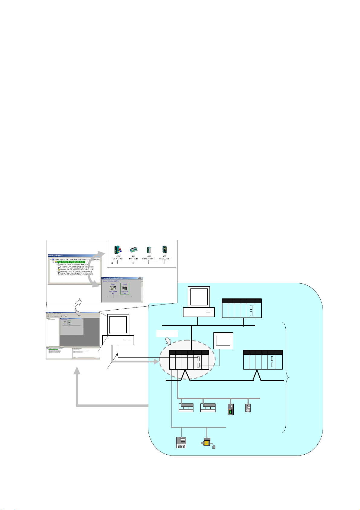
The CX-Integrator is a Programming Device software package that enables reading
the PLC's network and serial network configuration from a personal computer via an
online connection. This enables easily performing many operations, such as
monitoring the connection status of various networks, setting parameters, and
diagnosing networks.
The CX-Integrator can be placed online manually or automatically with the
CS/CJ-series PLC to which it is directly connected to enable uploading and monitoring
the network configuration (including device parameters) for that PLC or other network
PLCs for each network.
Direction connection to serial communications using the CompoWay/F protocol is also
possible without going through a PLC. The CompoWay/F network configuration can
be uploaded or automatic connection is possible using the NT Link protocol for
NS-series PTs and CS/CJ-series PLCs.
Furthermore, parameters in slaves on the networks can be set, edited, uploaded, and
downloaded.
Whenever required, network configuration information can be saved in files. The
configuration information in previously saved files can be later compared to the
actually current configuration.
Uploading and displaying network and serial
communications configuration of the t arget PLC for
each network
CS/CJ-series PLC
Computer running CX-Int egrator
Ethernet
Target PLC
CS/CJ-se ries PLC
General-purpose slaves,
such as I/O Terminals
CompoWa y/F
Temperature
Controller
Devic eNet
Smart Sensor
Serial
connection
(NT Link)
Controller Li nk
PL
Temperature Controller
or other device
Serial
communications/net
works that can be
accessed
Direct serial connection
(Toolbus or Host Link) or
network connection
Uploaded to computer
Online connection
Access
1-2
Page 31

1-1 The CX-Integrator
r
1-1-1 Overview
The network/serial communications configuration of a PLC other than the one
originally connected to online to can be set as the target. The PLC that was originally
connected to online (called the relay PLC, see note 1), is relayed through to connect
to another PLC (called the target PLC, see note 2) to switch the online connection.
Note 1: The relay PLC is the PLC to which an online connection was first made from the
computer through a network or serial connection.
Note 2: The target PLC is the PLC from which the network configuration can be uploaded.
Uploading and displaying network and serial
communications configurati on of the target PLC for each
network
Computer running
CX-Integrator
Onli ne
connection
Direct serial connect ion
(Toolbus or Host Link) or
network connection
Access
Uploaded to computer
A PLC other than the relay PLC
can be set as the target.
Relay PLC
CS/CJ-se ries PLC
Controller Link
Target PLC
CS/CJ-series
PLC
DeviceNe t
General-purpose slaves,
such as I/O Terminals
CompoWay/F
Ethernet
CS/CJ-series PLC
Serial connection
(NT Link)
PLC
Temperature
Controller or
other device
Serial
communications/net
works that can be
accessed
Temperature
Controlle
Smart Sensor
Direction connection from the CX-Integrator to serial communications using the
CompoWay/F protocol is also possible using RS-232C or RS-485 communications
without going through a PLC. The CompoWay/F network configuration can also be
uploaded.
Computer running
CX-Integrator
Standard RS-232C cable (female-female)
K3SC RS-232C to RS-485 Interface
Converter
RS-485 cable connection
CompoWay/F protocol
Uploaded to computer
Temperature
Controller
Smart Sensor
Smart Sensor
1-3
Page 32

1-1 The CX-Integrator
1-1-2 Functions According to Network
1-1-2 Functions According to Network
The functions for each network are listed in the following table.
Network Functions
DeviceNet, CompoNet, or CompoWay/F A virtual network or virtual serial communications
Controller Link or SYSMAC LINK User-set data link tables can be created offline
Controller Link A Controller Link Network Diagnostic Tool can be
Ethernet Broadcast node searches and ping tests are
NT Link Settings for an NS-series PT with a model number
FINS networks, such as Ethernet, Controller
Link, SYSMAC LINK, and DeviceNet
configuration can be created offline and connected
device parameters can be set, and data can be
uploaded, downloaded, and compared when
online.
and then transferred online to CS/CJ-series PLCs.
Data link parameters can be set automatically
online and then transferred to CS/CJ-series PLCs.
started to diagnose Controller Link networks.
enabled (with CX-Integrator Ver. 1.1 or higher).
ending in V1 or later serially connected to a
CS/CJ-series PLC via NT Link can be
automatically detected and set for the serial port of
the CS/CJ-series PLC. This is called NT Link Auto
Online Setting function.
Routing tables can be set offline and then
transferred online to CS/CJ-series PLCs.
Echoback tests between nodes are enabled (with
CX-Integrator Ver. 1.1 or higher).
1-1-3 Connecting to the Relay PLC
Either of the following methods can be used to connect the CX-Integrator online to the
relay PLC.
Serial communications (Toolbus or Host Link Mode)
FINS network communications, such as Controller Link
Ethernet FINS/TCP, or FinsGateway
Note: If the computer running the CX-Integrator is connected directly to a network, the network
address and node can be specified to set any PLC on the local network or an
interconnected network as the relay PLC.
*1: When running the CX-Integrator on Windows Vista or Window 7, an online connection
will not be possible to the relay PLC even if communications for one of these networks is
selected.
*2: If FinsGateway is selected, connection will not be possible to a DeviceNet, CompoNet,
or CompoWay/F network. To connect to any of these networks, use Ethernet, Ethernet
(FINS/TCP), Controller Link, or SYSMAC LINK instead of FinsGateway.
*2
(See note.)
*1
, SYSMAC LINK*1, Ethernet,
1-4
Page 33

1-1-4 Accessible Network
The network configuration of the target PLC (i.e., either the relay PLC or a PLC
connected to the relay PLC) can be uploaded and monitored for each of the following
networks.
Accessible Networks
Network Conditions
Ethernet Monitoring and editing parameters is possible for all CS/CJ-series PLCs
and NSJ-series NSJ Controllers on the Ethernet network. Only monitoring
the network configuration is possible for CVM1/CV-series PLCs and
computers with FinsGateway.
Controller Link Monitoring and editing parameters is possible for all CS/CJ-series PLCs
and NSJ-series NSJ Controllers on the Controller Link network. Only
monitoring the network configuration is possible for C200HX/HG/HS
PLCs, CVM1/CV-series PLCs, and computers with FinsGateway.
SYSMAC LINK Monitoring and editing parameters is possible for all CS-series PLCs on
the SYSMAC LINK network. Only monitoring the network configuration is
possible for C200HX/HG/HS PLCs, CVM1/CV-series PLCs, and
computers with FinsGateway.
DeviceNet Monitoring and editing parameters is possible for all CS/CJ-series
DeviceNet Units and NSJ-series NSJ Controllers. Only setting the
DeviceNet Master Unit is possible for C200H-series DeviceNet Master
Unit and CVM1/CV-series DeviceNet Master Units.
CompoNet Parameter and monitor editing is only supported only for CS/CJ-series
CompoNet Master Units and CompoNet Slave Units.
1-1 The CX-Integrator
1-1-4 Accessible Network
Accessible Serial Communications
Serial
communications
CompoWay/F The serial communications mode of the serial port must be Serial
Gateway Mode or Protocol Macro Mode. (See note.)
Note: To use the built-in serial ports on CS/CJ-series CPU Units, unit
version 3.0 or later must be used. For Serial Communications
Boards and Serial Communications Units, unit version 1.2 or later
must be used.
Monitoring and parameter editing is possible only for CompoWay/F slaves
for which CPS files have been installed on the computer running the
CX-Integrator.
(If the CompoWay/F slave is a Temperature Controller, however, only
monitoring the network configuration is possible. Parameters are edited
using the CX-Thermo.)
NT Link The serial communications mode of the serial port must be 1:N NT Link.
Monitoring is possible only for NS-series PTs with model numbers ending
in V1or later. (Monitoring is not possible for earlier NS-series PTs without
a model number suffix or for NT-series PTs.)
Conditions
1-5
Page 34

1-1 The CX-Integrator
1-1-4 Accessible Network
Local Network Table Requirements
A local network table must be registered in the target PLC in the following cases.
Communications Conditions
Network
communications
Serial
communications
Note: As an exception, local network tables are not required even when more than one Network
Communications Unit is mounted in the following situation:
Access is possible without a local network table when connecting online to the target PLC
via a direct serial connection and access is required only to the network of the Network
Communications Unit with the smallest unit number (set on the front panel rotary
switches) of all the Network Communications Units that are mounted to the target PLC.
• More than one Network Communications Unit is mounted to the target
PLC. (See note.)
Note: In this context, the following are Network Communications Units:
Ethernet Unit, Controller Link Unit, SYSMAC LINK Unit, DeviceNet
Unit, FL-net Unit, EtherNet/IP Unit, or built-in EtherNet/IP port. Serial
Communications Units and Serial Communications Boards are not
included except in the following case: If serial ports are registered in
the local network table to treat them as networks, the serial ports must
be treated as Network Communications Units, including the serial ports
on the CPU Unit. EtherNet/IP Units and built-in EtherNet/IP ports are
treated as Ethernet Units.
• Routing tables are already registered in one or more nodes on the network.
• Communications are required between networks.
Serial ports on Serial Communications Units and Serial Communications
Boards are used as serial gateways to Host Link FINS and access is
required via networks via Host Link FINS to PLCs functioning as Host Link
slaves.
Note: Serial ports do not necessarily need to be registered in the local
network table (to treat them as networks) to enable using other serial
gateway functions. Registration is normally not required to convert from
serial to serial. Refer to 3-6 Overview of Serial Gateway Functions in
the CS/CJ-series Communications Commands Reference Manual for
details on whether local network tables are required to use serial
gateway functions.
1-6
Page 35

1-1-5 Communicating Across Network Layers
p
1-1-5 Communicating Across Network Layers
If relay network routing tables are set in the CPU Units of the PLCs, a PLC on a
different network layer than the network of the PLC connected to the CX-Integrator
can be set as the target PLC to enable uploading, saving, and comparing the network
configuration of the target PLC.
Uploading and displaying network and serial communications configurati on
of a target PLC on a remote network for each network
Computer running
CX-Integrator
Relay PLC
Relay network routing tables
set in the CPU Units
1-1 The CX-Integrator
CS/CJ-series PLC
Controller Link
Serial connection
(Toolbus or Host
Link) or network
connection
Uploaded to computer
CS/CJ-series PLC
1-1-6 Starting Other Applications
The following applications can be started from the CX-Integrator.
Application Starting method
CX-Programmer Right-click the desired CS/CJ-series PLC in the Network
Configuration Window and select Start Special Application
from the pop-up menu.
Data Link Component Either select Tools – Start Data Link or right-click the desired
Controller Link Unit in the Online Connection Information
Window and select Start Data Link from the pop-up menu.
Routing Table Component Either select Tools – Start Routing table or right-click the
Controller Link Network Diagnostic
Tool
CX-Designer Right-click the desired NS-series PT in the Network
CX-Thermo Right-click the desired OMRON Temperature Controller in the
CX-Drive Right-click the desired Inverter or Servo in the Network
desired Communication Unit/port in the Online Connection
Information Window and select Start Routing table from the
pop-up menu.
Select Tools – Controller Link tool – Network diagnosis.
Configuration Window and select Start Special Application
from the pop-up menu.
Network Configuration Window and select Start Special
Application from the pop-up menu.
Configuration Window and select Start Special Application
from the pop-up menu.
Ethernet
Target PLC
CS/CJ-series PLC
General-purpose slaves, such
as I/O Terminals
DeviceNet
Serial connection
(NT Link)
Network and serial
communications
structure can be
u
PLC
loaded.
Temperature
Controller or
other device
1-7
Page 36

1-2 Specifications
1-2-1 CX-Integrator Specifications
1-2 Specifications
1-2-1 CX-Integrator Specifications
Item Specification
Model Provided in the CX-One FA Integrated Tool Package (CXONE-AL@@C-V4/ CXONE-AL@@D-V4).
Setup media CXONE-AL@@C-V4: CD-ROM
Applicable computers
(with FinsGateway)
PLCs that can be used as
relay PLC for online
connections
Note: A relay PLC is the
PLC to which the
CX-Integrator is connected
online.
CXONE-AL@@D-V4: DVD-ROM
Refer to the CX-One Setup Manual (W463) for the specifications required for computers to use
the CX-Integrator.
Note: To use CX-Integrator version 2.2 or higher, the display resolution must be XGA or better.
Series Device type
(See note 1.)
CS Series
CJ Series
CP-Series
(See note 3.)
NSJ Series NSJ
CS1H CS1H-CPU67/66/65/64/63(-V1)
CS1G/CJ1G CS1G-CPU45/44/43/42(-V1)
CS1G-H CS1G-CPU45H/44H/43H/42H
CS1H-H CS1H-CPU67H/66H/65H/64H/63H
CS1D-H CS1D-CPU67H/65H (See note 2.)
CS1D-S CS1D-CPU67S/65S/44S/42S
CJ2H CJ2H-CPU6@(-EIP)
CS1G/CJ1G CJ1G-CPU45/44
CJ1M CJ1M-CPU23/22/21/13/12/11
CJ1G-H CJ1G- CPU45H/44H/43H/42H
CJ1H-H
CP1H-XA CP1H-XA@@@@-@
CP1H-X CP1H-X@@@@-@
CP1H-Y CP1H-Y@@@@-@
CP1L-M CP1L-M@@@@-@
CP1L-L CP1L-L@@@@-@
CP1E CP1E-E@@D@-A
CJ1H-CPU67H/66H/65H
CJ1H-CPU67H-R/66H-R/65H-R/64H-R
CP1E-N@@D@-@
G5D (Used for the NSJ5-TQ0@-G5D, NSJ5-SQ0@-G5D,
NSJ8-TV0@-G5D, NSJ10-TV0@-G5D, and NSJ12-TS0@-G5D.)
M3D (Used for NSJ5-TQ0@-M3D, NSJ5-SQ0@-M3D, and
NSJ8-TV0@-M3D.)
CPU Unit model
Note 1: To connect the computer running CX-Integrator directly as a CompoWay/F slave,
set the Device type to CompoWay/F Device.
Note 2: When using a pre-Ver. 1.1 CS1D-H CPU Unit, use it as if it were a CS1H-H CPU
Unit.
Note 3: Use commercially available USB cable (B type to A type connectors) for
connecting CP-series CPU Units.
1-8
Page 37

Item Specification
Connecting to the
Relay PLC
1-2 Specifications
1-2-1 CX-Integrator Specifications
Either of the following can be used.
Serial
communications
FINS network
communications
*1: When running the CX-Integrator on Windows Vista or Windows 7, an online connection
will not be possible to the relay PLC even if communications for one of these networks is
selected.
*2: If FinsGateway is selected, connection will not be possible to a DeviceNet, CompoNet,
or CompoWay/F network. To connect to any of these networks, use Ethernet, Ethernet
(FINS/TCP), Controller Link, or SYSMAC LINK instead of FinsGateway.
Direction connection is possible to any of the following serial ports on a
CS/CJ/CP-series PLC.
• CPU Unit USB port (Toolbus)
• CPU Unit peripheral port (Toolbus or Host Link)
• CPU Unit RS-232C port (Toolbus or Host Link)
• A CP-series CPU Unit is connected to the USB port using a
commercially available USB cable (type B – type A).
• Serial Communications Board or Serial Communications Unit RS-232C
port or RS-422A/485 port (Host Link) (See note.)
Note: For a CP-series CPU Unit, connect to a CP1W-CIF01/11 Option
Board (Toolbus or Host Link).
Direct connection is possible to any of the following serial ports on an
NSJ-series NSJ Controller.
• RS-232C port A (Toolbus) on NSJ Controller
• RS-232C port B (Toolbus) on NSJ Controller
• USB port on NSJ Controller
Note: Automatic online connection is possible for serial communications
ports. (The user does not have to set the computer communications
settings.) The communications settings will be automatically set to
those of the PLC. Connection is possible to a serial port on the CPU
Unit, a Serial Communications Board, or a Serial Communications
Unit. For PLC serial ports, however, only the Toolbus or Host Link
serial communications modes can be used and the baud rate must
be 9600, 19200, 38400, or 115200 bits/s.
Direction connection is possible through any of the following networks on
a CS/CJ-series PLC or NSJ-series NSJ Controller.
• Ethernet (Ethernet, Ethernet FINS/TCP, or FinsGateway
• Controller Link (Controller Link
• SYSMAC LINK (SYSMAC LINK
*1
or FinsGateway*2)
*1
or FinsGateway*2)
*2
)
1-9
Page 38

1-2 Specifications
1-2-1 CX-Integrator Specifications
Item Specification
PLCs that are
accessible as target
PLCs
Note: The target PLC is
the PLC actually
being accessed,
e.g., to
upload/download
the PLC’s
network
configurations.
Windows • Network Configuration Window: Connected component configuration for each type of communications.
communications
Series Device type CPU Unit model
CS Series
CJ Series
CP-Series
NSJ Series NSJ
CS1H CS1H-CPU67/66/65/64/63(-V1)
CS1G/CJ1G CS1G-CPU45/44/43/42(-V1)
CS1G-H CS1G-CPU45H/44H/43H/42H
CS1H-H CS1H-CPU67H/66H/65H/64H/63H
CS1D-H CS1D-CPU67H/65H
CS1D-S CS1D-CPU67S/65S/44S/42S
CJ2H CJ2H-CPU6@(-EIP)
CS1G/CJ1G CJ1G-CPU45/44
CJ1M CJ1M-CPU23/22/21/13/12/11
CJ1G-H CJ1G- CPU45H/44H/43H/42H
CJ1H-H
CP1H-XA CP1H-XA@@@@-@
CP1H-X CP1H-X@@@@-@
CP1H-Y CP1H-Y@@@@-@
CP1L-M CP1L-M@@@@-@
CP1L-L CP1L-L@@@@-@
CP1E CP1E-E@@ D @-A
Note: When using a pre-Ver. 1.1 CS1D-H
CPU Unit, use it as if it were a
CS1H-H CPU Unit.
CJ1H-CPU67H/66H/65H
CJ1H-CPU67H-R/66H-R/65H-R/64H-R
CP1E-N@@ D @-@
G5D (Used for the NSJ5-TQ0@-G5D,
NSJ5-SQ0@-G5D, NSJ8-TV0@-G5D,
NSJ10-TV0@-G5D, and
NSJ12-TS0@-G5D.)
M3D (Used for NSJ5-TQ0@-M3D,
NSJ5-SQ0@-M3D, and NSJ8-TV0@-M3D.)
Note: CompoWay/F cannot be
used with a built-in serial
port on the CPU Unit.
Note: A CPU Unit with unit version
3.0 or later must be used
when using CompoWay/F
with a built-in serial port on
the CPU Unit
Note: CompoWay/F cannot be
used with a built-in serial
port on the CPU Unit.
Note: A CPU Unit with unit version
3.0 or later must be used
when using CompoWay/F
with a built-in serial port on
the CPU Unit
Note: CompoWay/F can be used
with a CP1W-CIF01/11
Option Board.
Note: CompoWay/F can be used
on serial port C (RS-232C
port) on the Controller
Section of the NSJ
Controller.
Note: The CS/CJ-series PLC must have a lot number of 030201 or later (manufactured 1 February
2003 or later) to start the CX-Designer and transfer screen data to an NS-series PT from the
CX-Designer through the PLC. The following PLCs can be used:
CS1G-H, CS1H-H, CS1D-S, CJ1M, or CJ1H-H. (The CS1D-H cannot be used.)
• System Overview: Interconnections between networks
The following communications are possible for a directly connected target PLC. Supported
Supported network
communications
• Ethernet (Access is possible only to CS/CJ-series PLCs, NS-series PTs,
and computers with FinsGateway on the Ethernet network. For
CVM1/CV-series PLCs, only display functions are supported.)
Note: With a CJ2H-CPU6@-EIP CPU Unit, connecting to an Ethernet
network is not possible from the built-in EtherNet/IP port or an
EtherNet/IP Unit port if the network connection is set for
EtherNet/IP. Always set Ethernet or Ethernet (FINS/TCP) to connect
to an Ethernet network.
• Controller Link (Access is possible only to CS/CJ/CP-series PLCs,
NS-series PTs, and computers with FinsGateway on the Controller Link
network.) For C200H-series PLCs and CVM1/CV-series PLCs, only
display functions are supported.)
Note: When the Controller Link Network Diagnosis application is being
used, it is possible to monitor and troubleshoot PLC models in the
Controller Link network other than CS/CJ-series PLCs.
• SYSMAC LINK (Monitoring is possible only to CS/CJ-series PLCs,
NS-series PTs, and computers with FinsGateway on the SYSMAC LINK
network.)
• DeviceNet (CS/CJ-series DeviceNet Units, C200H DeviceNet Master
Units, or CVM1/CV-series DeviceNet Master Units)
Note: A C200H-DRM21-V1 or CVM1-DRM21-V1 DeviceNet Master Unit
can be used through a CS/CJ-series DeviceNet Unit.
• CompoNet (CS/CJ-series CompoNet Master Units)
• The EtherNet/IP network cannot be used.
1-10
Page 39

Item Specification
Online Connection
Information Window
Communications
monitoring functions
1-2 Specifications
1-2-1 CX-Integrator Specifications
Supported serial
communications
Note: Accessing PLC Communications Across Network Layers
If relay network routing tables are set, a PLC on a different network layer than the network of the
PLC connected to the CX-Integrator can be set as the target PLC.
When the target PLC is online, Communications Units connected to the target PLC (referred to here
as simple “Communications Units”) are displayed as follows:.
Target Device, Target PLC CPU Unit model (network address) (node address)
• CPU Unit name [model] (network address) (-) (serial port FINS unit address)
• Communications Unit name [model] (network address) (node address) (unit number)
• Communications Unit name [model] (network address) (node address) (unit number)
Communications configuration information can be uploaded by right-clicking a Communications Unit
and selecting Transfer – Network to PC.
Ethernet Node information for FINS communications (CPU Unit model, Ethernet
Controller Link Information on nodes participating in the Controller Link network (CPU
SYSMAC LINK Information on nodes participating in the SYSMAC LINK network (CPU
DeviceNet Information on nodes connected to DeviceNet for which EDS files are
CompoNet Information on nodes connected to CompoNet for which DTM is installed
CompoWay/F Information on nodes connected to a serial port in serial gateway mode or
NT Link Information on nodes connected to 1:N NT Links (NS-series PT model
• CompoWay/F (CS/CJ-series CPU Units must be unit version 3.0 or later.)
Serial Communications Boards and Serial Communications Units must be
unit version 1.2 or later. Only slaves for which CPS files are installed on the
computer can be accessed.
• NT Links (Connection is possible only for NS-series PTs with model
numbers ending in V1 or later.)
Note: For the CJ2 CPU Units, connection is impossible when “USB” is
selected in the network settings. Select “USB (Toolbus)”.
Unit mode, node address, and network address)
Unit model, Controller Link Unit mode, node address, and network
address)
The following functions are also possible if the Controller Link Network
Diagnostic Tool is started.
Configuration node diagnosis (network participation status, current
Controller Link Unit errors, current CPU Unit errors, and differences from
node files), setting diagnosis (e.g., DM Area parameter setting
consistency), line disconnection information diagnosis, transmission
status diagnosis, node status (displaying current error status and error
log), error log collection, and node file editing (node names, connection
order, and Repeater Units)
Unit model, Controller Link Unit mode, node address, and network
address)
installed on the computer (DeviceNet Unit model, slave model,
master/slave node addresses)
on the computer (CompoNet Master Unit models, Slave Unit models,
Master/Slave Unit status)
protocol macro mode for which CPS files are installed on the computer
(CompoWay/F SLAVE model and CompoWay/F node address).
Note: CS/CJ-series CPU Units with unit version 3.0 or later, or Serial
Communications Boards/Units with unit version 1.2 or later, or
CP-series Communications Option Boards must be used.
and NT Link unit number)
Note: Automatic detection of NS-series PTs connected serially to a
CS/CJ-series PLC is also possible. (The NT Link Automatic Setting
Function automatically changes the setting of the PLC’s serial port
to match those of the NS-series PT.)
1-11
Page 40

1-2 Specifications
1-2-2 Files Created by the CX-Integrator
Item Specification
Setting functions
Verification functions Verifying communications/network configurations
Operations The following operations are possible for the CPU Unit at the target PLC.
Ethernet Ethernet Unit settings (CPU Bus Unit System Settings)
Controller Link
SYSMAC LINK
DeviceNet DeviceNet Unit master parameters (remote I/O allocations, connection
CompoNet CompoNet Master Unit parameters (Registration Table, message function
CompoWay/F CompoWay/F slave parameters (except for Temperature Controllers)
NT Link None
FINS networks, such
as Ethernet, Controller
Link, SYSMAC LINK,
and DeviceNet
Verifying component parameters
Creating, editing, and transferring I/O tables
Displaying current errors and error logs
Changing the operating mode
Transferring or verifying a manually set data link table
Transferring or verifying a routing table (FINS local routing table)
User-set data link tables
Controller Link and SYSMAC LINK Unit settings (in allocated DM Area
words), including automatically set data link parameters (transferred to
the startup node set as the target PLC)
settings, component information check, communications cycle time, etc.)
Slave parameters
enable/disable, settings of Input Data Clear Mode for Communications
Errors, Manual Start Mode for remote I/O communications, Software
Setting table)
CompoNet Slave parameters
Note: Parameters for CompoWay/F-compatible Temperature Controllers
are set using the CX-Thermo, started as an application.
PLC serial port communications settings (CPU Unit: part of PLC Setup,
Serial Communications Boards/Units: allocated DM Area words)
Routing tables (FINS local routing tables and FINS network routing
tables)
Note: The FINS local routing table is transferred to the target PLC.
1-2-2 Files Created by the CX-Integrator
The following files can be created by the CX-Integrator.
Files Contents Details
Project files (.cin) Connection
information to relay
PLC, all network
configurations for
target PLC, and
parameters for
DeviceNet masters,
DeviceNet slaves,
CompoNet masters,
CompoNet slaves,
and CompoWay/F
slaves
Network
configuration files
DeviceNet network
structure files (.npf)
These files are used offline to check network configurations and parameters
and for other purposes, such as printing. Each file consists of the following:
Device type setting information of the relay PLC
Communications Unit models connected to the target PLC (Ethernet Units,
Controller Link Units, SYSMAC LINK Units, DeviceNet Units, and Serial
Communications Boards/Units)
Device models connected to the above CPU Units or Communications
Units via communications (DeviceNet slaves, CompoNet slaves,
CompoWay/F slaves, NS-series PTs, etc.)
Parameters for DeviceNet Master Units and DeviceNet slaves (for all
devices for which EDS files are installed on the computer, including slaves
from other manufacturers)
Parameters for CompoNet Master Units and CompoNet slaves (for all
devices for which DTM is installed on the computer, including slaves from
other manufacturers)
Parameters for CompoWay/F slaves (for all components for which CPS
files are installed on the computer (except for Temperature Controllers)
Controller Link network parameters
Controller Link and SYSMAC LINK Unit allocated DM Area words settings,
including automatically set data link parameters
Ethernet Unit CPU Bus Unit System Settings
Serial Communications Board/Unit serial communications settings
Note: Routing tables (local network tables and relay network tables) and
user-set data link tables are not included in project files.
Network configuration for one DeviceNet network connected directly to the
target PLC (including master and slave parameters)
Note: These are the same as the DeviceNet network structure files (.npf)
created with DeviceNet Configurator version 2.@. Files created with
DeviceNet Configurator version 2.@ can be imported/exported.
1-12
Page 41

Files Contents Details
Controller Link node
Component
parameter files
Data link table files
Routing table files
files (.crg)
DeviceNet device
parameter files
(.dvf)
CompoWay/F
component
parameter files
(.xml)
Controller Link data
link table files (.cl2)
SYSMAC LINK data
link table files (.sl3)
FINS local routing
table files (.rtg, .rxg)
(See note 2.)
FINS network
routing table files
(.rt3, .rx3)
(See note 2.)
Network configuration for Controller Link networks connected directly to the
target PLC
Parameters for individual DeviceNet devices (master or slave)
Note: These are the same as the DeviceNet device parameter files (.dvf)
created with DeviceNet Configurator version 2.@. Files created with
DeviceNet Configurator version 2.@ can be imported.
Parameters for individual CompoNet devices (master or slaves)
Parameters for individual CompoWay/F slaves (except for Temperature
Controllers)
CPU Unit parameters (parts of PLC Setup: serial communications settings)
Controller Link or SYSMAC LINK network parameters
Controller Link and SYSMAC LINK Unit allocated DM Area words settings,
including automatically set data link parameters
Ethernet Unit CPU Bus Unit System Settings
Serial Communications Board/Unit serial communications settings
Controller Link user-set data link tables
Note: These are the same as the Controller Link data link table files (.cl3)
created with the CX-Net. Files created with the CX-Net can be
imported.
SYSMAC LINK user-set data link tables
Note: These are the same as the SYSMAC LINK data link table files (.sl3)
created with the CX-Net. Files created with the CX-Net can be
imported.
Routing tables of the target PLC
Note 1: These are the same as the FINS local routing table files (.rtg, .rxg)
created with the CX-Net. Files created with the CX-Net can be
imported.
Note 2: Standard number of relay network table entries (20 max.): .rtg
Extended number of relay network table entries (64 max.): .rxg
Routing tables for all PLCs on networks to which the target PLC belongs
Note 1: These are the same as the FINS network routing table files
(.rt3, .rx3) created with the CX-Net. Files created with the CX-Net
can be imported.
Note 2: Standard number of relay network table entries (20 max.): .rt3
Extended number of relay network table entries (64 max.): .rx3
Note With DeviceNet only, the following files can also be exported and saved.
EDS files (.eds)
The device list saved in CSV format (.csv)
The I/O comments saved in CSV format (.csv)
The device parameters of an OMRON DeviceNet Master Unit saved as an Open
Network Controller DRM_UNIT (virtual unit) file
The device parameters of an OMRON DeviceNet Master Unit saved as a NetX Server
(NetX Server for DeviceNet) file
Note The CX-Integrator does not support files created in the DeviceNet Configurator Ver.
1.0 file format.
1-2 Specifications
1-2-2 Files Created by the CX-Integrator
1-13
Page 42

1-3 Installation
1-3 Installation
The CX-Integrator is installed from the CX-One Installer. Refer to the CX-One Ver. 4.@
Setup Manual (W463) for details.
1-14
Page 43

1-4-1 Direct Serial Connections to a PLC
1-4 PLC Connecting Cables
1-4-1 Direct Serial Connections to a PLC
When connecting the computer running the CX-Integrator directly to a PLC using a
serial line, make the connection correctly using the following Connecting Cables and
connection diagrams.
Connecting Cables to CS/CJ-series PLCs
Unit Unit port Computer
CPU Unit
Built-in
peripheral port
IBM PC/AT
or
Computer
port
D-sub
9-pin male
compatible
Built-in
RS-232C port
D-sub 9-pin
IBM PC/AT
or
compatible
D-sub
9-pin male
female
USB port IBM PC/AT
USB port Peripheral bus
or
compatible
Serial
Communications
Boards/Units
RS-232C port
D-sub 9-pin
female
IBM PC/AT
or
compatible
D-sub
9-pin male
Refer to the following connection diagrams.
Connection t o IBM PC/AT or Compatible
Connection t o Peripheral Port
IBM PC/AT or compatible
Connection t o RS-232C Port
IBM PC/AT or compatible
Network type
(serial
communications
mode)
Peripheral bus
(Toolbus)
or Host Link
(SYSWAY)
Peripheral bus
(Toolbus)
or Host Link
(SYSWAY)
Host Link
(SYSWAY)
(Toolbus)
Host Link
(SYSWAY)
1-4 PLC Connecting Cables
Model Length Remarks
CS1W-CN226/626 2 m/6 m ---
XW2Z-200S-CV/
500S-CV
XW2Z-200S-V/
500S-V
--- --- ---
XW2Z-200S-CV/
500S-CV
XW2Z-200S-V/
500S-V
2 m/5 m Connector
with ESD
(electrostatic
discharge)
countermeasures
used.
2 m/5 m ---
2 m/5 m Connector
with ESD
(electrostatic
discharge)
countermeasures
used.
2 m/5 m ---
9-pin
CS1W-CN226 (2.0 m)
CS1W-CN626 (6.0 m)
CPU Unit peri pheral port
9-pin
XW2Z-200S-CV ( 2.0 m)
XW2Z-500S-CV ( 5.0 m)
9-pin
Built- in RS-232C
port on CP U Unit
or port on Ser ial
Communicat ions
Board/Unit
Note
•When using an RS-232C cable for the computer running CX-Integrator and
connecting to a CS/CJ-series PLC with a Toolbus connection, use a
XW2Z-200S-CV/500S-CV Connecting Cable. (This cable can be used only with IBM
PC/AT or compatible computers.)
•The following connection methods can be used when connecting an RS-232C cable
to a peripheral port on a CS/CJ-series PLC.
1-15
Page 44

1-4 PLC Connecting Cables
p
p
1-4-1 Direct Serial Connections to a PLC
Unit Unit port Computer
CPU Unit Built-in
peripheral port
IBM
IBM
PC/AT or
compatible
PC/AT or
compatible
Connection to
RS-232C Port
XW2 Z-
@@@S-@@
RS-232C cable
(listed above)
Computer
D-sub 9-pin
male
D-sub 9-pin
male
port
Network type
(serial
communications
mode)
Peripheral bus
(Toolbus)
or Host Link
(SYSWAY)
Host Link
(SYSWAY)
Model Length Remarks
CS1W-CN118 +
XW2Z-200S-CV/
500S-CV
CS1W-CN118 +
XW2Z-200S-V/
500S-V
0.1 m +
2 m/5 m
0.1 m +
2 m/5 m
The
XW2Z-@@@
S-CV uses a
connector
with ESD
(electrostatic
discharge)
countermeasures.
---
CS1W-CN118
heral port
Peri
Note The following connection methods can be used when connecting an CQM1-CIF01/02
cable to a peripheral port on a CS/CJ-series PLC.
Unit Unit port Computer
CPU Unit Built-in peripheral
port
IBM
PC/AT or
compatible
Computer
port
D-sub 9-pin
male
Network type
(serial
communications
mode)
Host Link
(SYSWAY)
Note: Baud rate
must be 19.2
Kbits/s or less.
Model Length Remarks
CS1W-CN114 +
CQM1-CIF02
0.05 m +
3.3 m
---
Connection to
RS-232C Port
CQM1-CIF01/02
Peripheral Cable
CS1W-CN114
Peri
heral port
1-16
Page 45

Note Connecting the PLC Using a USB Port on the Computer
Computer
running
CX-Integrator
1-4 PLC Connecting Cables
1-4-1 Direct Serial Connections to a PLC
A USB port on the computer can be used to connect the computer running the
CX-Integrator to a CS/CJ-series PLC. To do so, connect the computer to the PLC as
shown below using a CS1W-CIF31 USB-Serial Conversion Cable.
The driver software included with the CJ1W-CIF31 must be installed on the computer
to use a USB port to connect the CX-Integrator. Refer to the PDF User’s Manual
included with the CS1W-CIF31 USB-Serial Conversion Cable for details.
When connecting the computer to a CP-series PLC, it is possible to make a direct
connection using a commercially available USB cable (B type – A type connectors).
PLC Connection Methods
CS1W-CIF31 Cable 1
CS1W-N226/626 CS/CJ-series
Peripheral Port Programming
Device Connecting Cable
or
CS1W-CIF31
USB Connecting Cable
+
CQM1H-CIF02 C-series
Peripheral Port Programming
Device Connecting Cable
or
@@@
XW2Z-
RS-232C Programming
Device Connecting Cable
CS1W-CN114
C-series-CS/CJ-series
Peripheral Conversion Cable
+
Cable 2
(when required)
CS1W-CN118
RS-232C-CS/CJ-series
Peripheral Conversion Cable
PLC
CS/CJ-series CPU Unit Connection Patterns
USB
Connecting
Cable
Model Connector Model Connector Connector Model Connector
CS1W-CIF31
D-sub 9-pin
female
D-sub 9-pin
female
D-sub 9-pin
female
D-sub 9-pin
female
D-sub 9-pin
female
D-sub 9-pin
female
Cable 1
CS1W-CN226/626
(length: 2 m/6 m)
CQM1-CIF02
(length: 3.3 m)
XW2Z-200S-CV
/500S-CV
(length: 2 m/5 m)
XW2Z-200S-V
/500S-V
(length: 2 m/5 m)
XW2Z-200S-CV
/500S-CV
(length: 2 m/5 m)
XW2Z-200S-V
/500S-V
(length: 2 m/5 m)
CS/CJ
peripheral
C peripheral C peripheral CS1W-CN114
D-sub 9-pin
male
D-sub 9-pin
male
RS-232C
D-sub 9-pin
male
RS-232C
D-sub 9-pin
male
D-sub 9-pin
female
D-sub 9-pin
female
Cable 2
Not needed.
(length: 5 cm)
CS1W-CN118
(length: 0.1 m)
CS1W-CN118
(length: 0.1 m)
Not needed.
Not needed.
CS/CJ
peripheral
CS/CJ
peripheral
CS/CJ
peripheral
Port Serial
communications
CS/CJ
peripheral
RS-232C
D-sub 9-pin
female
mode
(network
type)
Peripheral
(Toolbus)
or Host Link
(SYSWAY)
Host Link
(SYSWAY)
Peripheral
(Toolbus)
or Host Link
(SYSWAY)
Host Link
(SYSWAY)
Peripheral
(Toolbus)
or Host Link
(SYSWAY)
Host Link
(SYSWAY)
1-17
Page 46

1-4 PLC Connecting Cables
1-4-1 Direct Serial Connections to a PLC
Connection diagrams are shown below.
Connecting to the Peripheral Port
• Using the CS1W-CN226/626 Connecting Cable
USB A-plug connector,
male
CS1W-CIF31
D-sub connector
(9-pin male)
D-sub connector
(9-pin female)
Recommended cable:
CS1W-CN226/626
• Using the CQM1-CIF02 Connecting Cable
●
CS/CJ-series PLCs
●
Customizable Counter Units
CS/CJ peripheral connector
Peripheral port
USB A-plug connector,
male
CS1W-CIF31
D-sub connector
(9-pin male)
D-sub connector
(9-pin female)
Recommended cable:
CQM1-CIF02
C peripheral connector
● CS/CJ-series PLCs (See note.)
CS/CJ peripheral connector
CS1W-CN114
Peripheral port
Note: Only a Host Link connection is possible for CS/CJ-series PLCs.
1-18
Page 47

1-4 PLC Connecting Cables
1-4-1 Direct Serial Connections to a PLC
• Using the XW2Z-200S-CV/500S-CV or XW2Z-200S-V/500S-V Connecting Cable for
RS-232C
USB A-plug connector,
male
CS1W-CIF31
D-sub connector
(9-pin male)
CS/CJ peripheral
connector
Peripheral port
D-sub connector
(9-pin female)
XW2Z-200S-CV/500S-CV
XW2Z-200S-V/500S-V (See note.)
or
CS/CJ-series PLCs
D-sub connector (9-pin male)
D-sub connector
(9-pin female)
CS1W-CN118
Note: Only a Host Link connection is possible for CS/CJ-series PLCs.
• Using the XW2Z-200S-CV/500S-CV or XW2Z-200S-V/500S-V Connecting Cable for
RS-232C
USB A-plug connector,
male
CS1W-CIF31
D-sub connector
(9-pin male)
D-sub connector
(9-pin female)
CS/CJ-series PLCs
D-sub connector
(9-pin male)
RS-232C port
D-sub connector
(9-pin female)
Recommended cable:
XW2Z-200S-CV/500S-CV
or
XW2Z-200S-V/500S-V (See note.)
Note: Only a Host Link connection is possible for CS/CJ-series PLCs.
1-19
Page 48

1-4 PLC Connecting Cables
1-4-1 Direct Serial Connections to a PLC
Connecting Cables for CP-series PLCs
Connecting to USB Port in CPU Unit Using Commercially Available USB Cable
Unit Port at
Unit
CPU
Unit
USB port
(B
connector)
Computer Port at
DOS/V USB port
DOS/V computer
computer
(A
connector)
Network type
Model Length Remarks
(serial
communications
mode)
USB Cable
for
5 m
max.
USB
1.1 or
2.0
---
Commerciallyavailable USB
cable
Peripheral USB port
USB port
CP1H CPU Unit
Connecting by RS-232C Cable to the RS-232C Port in a Serial Communications
Option Board
Unit Unit port Computer Computer
port
CP1WCIF01
Serial
Option
Board
RS-232C
port, D-SUB
9-pin,
female
IBM
PC/AT or
compatible
D-SUB
9-pin, male
Network type
(serial
communications
mode)
Peripheral
(Toolbus) or
Host Link
(SYSWAY)
Host Link
(SYSWAY)
Model Length Remarks
XW2Z200S-CV/
500S-CV
XW2Z-200
S-V/500S-V
2 m/
5 m
2 m/
5 m
Connect
or with
ESD
(electrostatic discharge)
countermeasure
used.
---
1-20
Page 49

1-4 PLC Connecting Cables
1-4-2 Connecting CJ-series CJ2 CPU Units, CP-series PLCs and NSJ-series Controllers
Using Commercially Available USB Cable
1-4-2 Connecting CJ-series CJ2 CPU Units, CP-series PLCs and
NSJ-series Controllers Using Commercially Available USB
Cable
A computer running the CX-One can be connected to the peripheral USB port on a
CJ-series CJ2 CPU Units or a CP-series PLC or to the USB connector (SLAVE) on an
NSJ-series Controller using commercially available USB cable. The procedures are
provided in this section.
Restrictions when Connecting by USB
Due to USB specifications, the following restrictions apply when connecting a
computer running Support Software.
• A USB connection is possible for only one CP-series PLC from a single computer. It
is not possible to connect multiple CP-series PLCs or an NSJ-series Controller
simultaneously.
• Do not disconnect the USB cable while the Support Software is connected online.
Before disconnecting the USB cable, be sure to place the application in offline status.
If the USB cable is disconnected while online, the situations described below will
occur.
The Support Software cannot be returned to online status by simply reconnecting the
USB cable. First return the Support Software to offline status, and then reconnect the
USB cable. Then perform the online connection procedure for the Support Software.
CJ-series CJ2 CPU Units
Commercially
available USB
cable
The peripheral USB port (conforming to USB 1.1, B connector) is a dedicated port for
connecting Support Software, such as the CX-Programmer.
1-21
Page 50

1-4 PLC Connecting Cables
(
)
1-4-2 Connecting CJ-series CJ2 CPU Units, CP-series PLCs and NSJ-series Controllers
Using Commercially Available USB Cable
CP-series PLCs
The peripheral USB port (conforming to USB 1.1, B connector) is a dedicated port for
connecting Support Software, such as the CX-One (e.g., CX-Programmer).
NSJ-series Controllers
Personal computer
CX-One
USB port
Commercially
available USB
cable
NSJ-series
Controller
(bottom)
USB
connector
SLAVE
The USB port (SLAVE, conforming to USB 1.1, B connector) is a dedicated port for
connecting Support Software, such as the CX-One (e.g., CX-Designer and
CX-Programmer).
Items Required for USB Connection
Operating system Windows 2000, XP, Vista, or 7
Support Software CX-One (e.g., CX-Designer and CX-Programmer)
USB driver Included with above Support Software.
USB cable USB 1.1(or 2.0) cable (A connector-B connector), 5 m max.
1-22
Page 51

1-4 PLC Connecting Cables
1-4-2 Connecting CJ-series CJ2 CPU Units, CP-series PLCs and NSJ-series Controllers
Using Commercially Available USB Cable
Installing the USB Driver
Use the following procedure when connecting the personal computer to the peripheral
USB port for the first time. It is assumed that the Support Software has already been
installed.
Windows 2000, Vista, or 7
1. Turn ON the power supply to the PLC and connect the peripheral USB port on the
PLC to the personal computer using a USB cable. The USB driver will be
automatically installed when the cable is connected.
Note: If the software is not automatically installed, refer to Installing a Specified USB Driver later
in this section.
Windows XP
1. Turn ON the power supply to the PLC and connect the peripheral USB port on the
PLC to the personal computer using a USB cable. The computer will automatically
detect the device when the cable is connected and display the following message.
2. The following dialog box will be displayed. Select one of the options and click the
Next Button.
1-23
Page 52

1-4 PLC Connecting Cables
1-4-2 Connecting CJ-series CJ2 CPU Units, CP-series PLCs and NSJ-series Controllers
Using Commercially Available USB Cable
3. The following dialog box will be displayed. Select the Install the software
automatically (Recommended) Option and click the Next Button.
Note 1: If the software cannot be installed automatically, refer to Installing a Specified USB
Driver later in this section.
2: If the installation media is not inserted or the USB device driver is installed for another
port, a Driver List Dialog Box will be displayed. Make sure that the newest driver is
selected and click the Next Button.
1-24
Page 53

1-4 PLC Connecting Cables
1-4-2 Connecting CJ-series CJ2 CPU Units, CP-series PLCs and NSJ-series Controllers
Using Commercially Available USB Cable
4. Ignore the following dialog box if it is displayed and click the Continue Anyway
Button.
5. The following dialog box will be displayed if the installation is completed normally.
Click the Finish Button.
Installing a Specified USB Driver
If the USB driver cannot be installed automatically, use the following procedure to
install it.
Windows Vista or Windows 7
1. Turn ON the power supply to the PLC and connect the peripheral USB port on the
PLC to the personal computer using a USB cable.
1-25
Page 54

1-4 PLC Connecting Cables
1-4-2 Connecting CJ-series CJ2 CPU Units, CP-series PLCs and NSJ-series Controllers
Using Commercially Available USB Cable
2. The following dialog box will be displayed. Select Locate and install driver
software (Recommended).
3. The following dialog box will be displayed. Select I don’t have the disc. Show me
other options.
1-26
Page 55

1-4 PLC Connecting Cables
1-4-2 Connecting CJ-series CJ2 CPU Units, CP-series PLCs and NSJ-series Controllers
Using Commercially Available USB Cable
4. The following dialog box will be displayed. Click the Browse Button, specify the
following location, and then click the Next Button.
C:\Program Files\OMRON\CX-Server\USB\wind2000_XP\inf
5. Ignore the following dialog box if it is displayed and select Install this driver
software anyway.
6. The following dialog box will be displayed when the driver software has been
installed successfully.
1-27
Page 56

1-4 PLC Connecting Cables
1-4-2 Connecting CJ-series CJ2 CPU Units, CP-series PLCs and NSJ-series Controllers
Using Commercially Available USB Cable
Windows XP
1. In the Found New Hardware Wizard Dialog Box, select the Install from a list or
specific location (Advanced) Option and click the Next Button.
2. The following dialog box will be displayed. Click the Browse Button for the Include
this location in the search Field, specify C:\Program Files\OMRON\CX-Server\
USB\win2000_XP\Inf, and then click the Next Button. The driver will be installed.
(“C:\” indicates the installation drive and may be different on your computer.)
1-28
3. Ignore the following dialog box if it is displayed and click the Continue Anyway
Button.
Page 57

1-4 PLC Connecting Cables
1-4-2 Connecting CJ-series CJ2 CPU Units, CP-series PLCs and NSJ-series Controllers
Using Commercially Available USB Cable
4. The following dialog box will be displayed if the installation is completed normally.
Click the Finish Button.
Windows 2000
1. Turn ON the power supply to the CPU Unit, and connect USB cable between the
USB port of the computer and the peripheral (USB) port.
After the cable has been connected, the computer will automatically recognize the
device and the following message will be displayed.
2. The following message will be displayed. Click the Next Button.
1-29
Page 58

1-4 PLC Connecting Cables
1-4-2 Connecting CJ-series CJ2 CPU Units, CP-series PLCs and NSJ-series Controllers
Using Commercially Available USB Cable
3. The following dialog box will be displayed. Select the Search for a suitable driver for
the device (recommended) Option and then click the Next Button.
4. The following dialog box will be displayed. From the list in the dialog box, select the
Specify location Checkbox and then click the Next Button.
5. Click the Browse Button, specify C:\Program Files\OMRON\CX-Server\USB\
win2000_XP\Inf, and then click the Next Button. (“C:\” indicates the installation drive
and may be different on your computer.)
6. A search will be made for the driver and the following dialog box will be displayed.
Click the Next Button. The driver will be installed.
1-30
Page 59

1-4 PLC Connecting Cables
1-4-2 Connecting CJ-series CJ2 CPU Units, CP-series PLCs and NSJ-series Controllers
Using Commercially Available USB Cable
7. After the driver has been successfully installed, the following dialog box will be dis-
played. Click the Finish Button.
Checking after Installation (Reference Information)
1. Display the Device Manager at the computer.
2. Click USB (Universal Serial Bus) Controller, and confirm that OMRON SYSMAC
PLC Device is displayed.
1-31
Page 60

1-4 PLC Connecting Cables
1-4-2 Connecting CJ-series CJ2 CPU Units, CP-series PLCs and NSJ-series Controllers
Using Commercially Available USB Cable
Re-installing the USB Driver
If the USB driver installation fails for some reason or is cancelled in progress, the USB
driver must be reinstalled.
Checking USB Driver Status
1. Display the Device Manager on the computer.
2. If the OMRON-PLC is displayed under Universal Serial Bus controllers, installation
of the USB driver software failed.
Re-installing the USB Driver
1. Right-click OMRON-PLC under Universal Serial Bus controllers and select Proper-
ties. The properties will be displayed.
1-32
Page 61

1-4 PLC Connecting Cables
1-4-2 Connecting CJ-series CJ2 CPU Units, CP-series PLCs and NSJ-series Controllers
Using Commercially Available USB Cable
2. Click the Reinstall Driver Button. The Hardware Update Wizard Dialog Box will be
displayed. Install the driver software using the procedure described in Installing the
USB Driver.
1-33
Page 62

1-5 Window Descriptions
1-5-1 Starting Methods
1-5 Window Descriptions
1-5-1 Starting Methods
The CX-Integrator can be started with any of the following three methods.
1) When using the CX-Programmer Ver. 6.0 or higher, select Tools
Settings.
2) When using the CX-Programmer that was installed from the CX-One, right-click a
Communication Unit in the CX-Programmer’s I/O table display and select Start
Special Application from the pop-up menu.
Note: If the Communication Unit is a Serial Communications Board/Unit, a Start Special
Application Dialog Box will be displayed. Select CX-Integrator in the dialog box to start
the CX-Integrator.
3) Select CX-Integrator from the Start Menu.
1-5-2 Main Window
One of the following windows will appear when the CX-Integrator is started.
Offline Window
−
Network
Workspace Window
Note: The Component List Window and Output Window are not displayed by default. They can
be displayed using the View
Online Window
Workspace Window
−
Windows Menu.
Network Configuration Window
Network Configuration Window
1-34
Online Connection
Information Window
Page 63

1-5 Window Descriptions
=
1-5-2 Main Window
Note The following operations can be performed on the Workspace Window, Output
Window, Component List Window, and Outline Window.
Moving a Window and Displaying the Window Separately
Drag the window by its top border to move it.
Closing a Window
Click the X Button (Close Button) at the upper-right corner of the window.
Displaying a Window
Select the desired window from the View
−
Windows Menu. (A check mark appears
next to the windows that are displayed.)
Online Connection Information Window
The Online Connection Information Window displays the online/offline status and the
Relay PLC’s communications settings.
When online, the target PLC will be displayed in a tree structure with all of the
Communications Units and ports that belong to it.
Online Operation
The target PLC and Communication Units/ports mounted to the target PLC will be
listed below the relay PLC.
Relay PLC Communications Settings
The relay PLC’s communications settings will be displayed to the right of the Online
icon (
Online).
After Connecting Online
Relay PLC
Target PLC
Target PLC Information
Target PLC [CJ1M-CPU22] Net (0), Node (0)
Description:
In brackets
[ ] to the right of
TargetPLC
Target PLC’s
CPU Unit model
1) [Target PLC’s CPU Unit
Target PLC’s CPU Unit
model
The target PLC is displayed in green.
model]
Network address (1 to 127,
decimal)
Note: This is the network
When the computer is directly
connected to a PLC, the same
PLC will be both the relay PLC
and the target PLC.
3) Node address
2) Network address
1) Target PLC’s CPU Unit model
2) Network address 3) Node address
Node address (decimal)
Note: This is the node
address on the
address registered when
this PLC is registered as
the target PLC via the
relay PLC.
network registered
when this PLC is
registered as the
target PLC via the
relay PLC.
1-35
Page 64

1-5 Window Descriptions
1-5-2 Main Window
Communications Unit and Port Information for Target PLC
The following CPU Unit built-in serial ports, Inner Boards, and Communications Units
(referred to here as Communications Units/Ports) that are part of the target PLC are
displayed under TargetPLC in directory tree format.
Connection status
Description:
Communications
Unit/port
CPU Unit built-in
serial port
Serial port on
Inner Board
(Nothing
displayed if an
Inner Board is not
mounted.)
Communications
Unit name, Model
CPU port [CJ1M-CPU22] Net
(−) Node
(2) Unit
(0)
5) Unit number of FINS unit address
4) Node address
3) Network address
2) Unit model
1) Unit name
: Not connected (access not possible)
: Connected (access possible)
1) Right of or :
Unit name
CPU Unit/port Target PLC’s
Serial Communications
Board
Communications Unit
name (Ethernet Unit,
Controller Link Unit,
SYSMAC LINK Unit, or
DeviceNet Unit)
CompoNet Master Unit
name
2) Unit model 3) Network address
CPU Unit
model
Serial Communications
Board model
Communicatio
ns Unit model
The network address
(1 to 127, decimal),
when the serial port is
registered in the local
network table to treat
it as a network.
Note: “−” will be
displayed if the
serial port is not
registered in the
local network
table.
Same as above. − (Does not
Network address (1 to
127, decimal)
Note: “−” will be
displayed if a local
network table is not
registered.
− (Does not change.) − (Does not
4) Node
address
− (Does not
change.)
change.)
Node
address
(node ID on
the network)
change.)
5) Unit number or
FINS unit address
Serial port’s FINS
unit address
(decimal)
Peripheral port: 253
RS-232C port: 252
Note: “−” will be
displayed if
the serial port
is not
registered in
the local
network
table.
Serial port’s FINS
unit address
(decimal)
Port 1: 225
Port 2: 226
Note: “−” will be
displayed if
the serial port
is not
registered in
the local
network
table.
Unit number
(decimal)
(Rotary switch on
front of CPU Bus
Unit: 0 to 15)
Unit number
(decimal)
(Master Unit rotary
switch number: 0 to
99)
If a connection is established and access is enabled for a Communications Unit/port,
the icon on the left will be
instead of .
Right-click the Communications Unit/port and select Connect to connect to the
Communications Unit/port and enable access. (With the CX-Integrator, only one
Communications Unit/port can be accessed at any one time.)
The actual network configuration can then be uploaded by right-clicking the
Communications Unit/port and selecting Transfer
−
Network to PC.
1-36
Page 65

1-5 Window Descriptions
1-5-2 Main Window
Online Connect ion
Information Window
Target PLC displayed in green.
Note: If an online connection is
made to the relay PLC, the relay
PLC will also be the target PLC
by default.
The
the Communication Unit/port that is
presently connected and accessible.
Note CX-Integrator Communications Connections
Network Type
COM Port No., Baud Rate, Parity, Data
Bits, Stop Bits
Relay PLC’s CPU Unit model
Online displayed.
icon will be displayed next to
Unit No.
Node Address
Network Address
Communications Unit model (CPU Unit model for CPU Unit built-in serial ports)
Communications Unit name (CPU Unit for CPU Unit built-in serial ports)
Relay PLC’s FINS destination network
address
Relay PLC’s FINS destination node
address
Target PLC’s CPU Unit model
Target PLC’s network address
Target PLC’s node address
Communications Unit and port information
for target PLC
Displayed from the top in the following order.
CPU ports: CPU Unit serial ports
•
Inner Boards (Nothing is displayed if no
•
Inner Boards are mounted.)
Communications Units
•
Target PLC
information
Note: If an online connection is made to the relay PLC, that PLC will be both the relay PLC and
the target PLC. The Communications Units mounted in the relay PLC will be displayed in
the Online Connection Information Window. Normally, the CX-Integrator is used with the
same PLC as both the relay PLC and the target PLC.
Once a connection has been made, it is possible to download the network configuration
and switch the target PLC to any PLC on the network. To do this, right-click a PLC on a
network and select Connect to this PLC.
There are three levels of CX-Integrator communications connections depending on
where the connection is made.
Relay PLC
communications
settings
1-37
Page 66

1-5 Window Descriptions
1-5-2 Main Window
Display in Online
Connection
Information
Window
1) Online connection
to the relay PLC
Online
2) Status Online
connection to the
target PLC
TargetPLC or
TargetComponent
(See note.)
3) A connection to one
of the
Communications
Units/ports at the
target PLC (Access
is possible.)
Note: To connect the computer (CX-Integrator) directly to a CompoWay/F Slave through a
serial connection, select CompoWay/F Device as the PLC model.
Offline Displays
Level Operation Remarks
Right-click the
communications settings
for the relay PLC and
select Auto Online or
Remember that this icon
indicates that the online
connection is to the relay
PLC.
Work Online.
The operation is the same
as above when the relay
PLC is the target PLC.
If the target PLC is
different from the relay
PLC, upload the
communications
configuration, right-click
the target PLC, and select
Connect to this PLC.
An online connection to the
target PLC is made after
connecting online to the relay
PLC, as described above.
The following operations are
possible for the CPU Unit at
the target PLC.
I/O tables: Creating, editing,
and transferring I/O tables
Error log: Displaying current
errors and error
logs Mode setting:
Changing the
operating mode
Right-click the
Communications Unit/port
and select Connect.
Only one Communications
Unit/port can be accessed at
any one time.
Communications
configurations can be
uploaded only for a
Communications Unit/port in
this status.
Note: Access is possible to a
Communications
Unit/port only when it is
connected. Access is
not possible when
disconnected.
1-38
Online Connection
Information Window
Relay PLC Communications Settings
Network Type
COM Port No., Baud Rate, Parity, Data
Bits, Stop Bits
Offline displayed.
Relay PLC’s CPU Unit
Relay PLC’s FINS dest ination network address
Relay PLC’s FINS destination node
Relay PLC
communications
settings
Page 67

1-5 Window Descriptions
C
’
1-5-2 Main Window
Relay PLC Communications Settings
Offline Toolbus COM1, 19200,None8, 1 [CJM-CPU22] Net (0), Node (0)
9) Relay PLC’s FINS destination node
address (decimal)
8) Relay PlC’s FINS destination
network address (decimal)
7) Relay PL
6) Stop Bits
5) Data Bits
4) Parity
3) Baud Rate
2) COM Port No.
1) Network Type
Description:
Display item 1) Network Type
Contents The following network
types will be displayed for
the connection to the
relay PLC.
Toolbus (peripheral)
SYSMAC WAY (Host
Link)
SYSMAC LINK
Ethernet
Ethernet (FINS/TCP)
FinsGateway
Controller Link
Example Toolbus COM1, 19200, None, 8, 1
2) COM Port
No.
COM port on
computer
3) Baud Rate 4) Parity 5) Data Bits 6) Stop Bits
(Displayed
only for
Toolbus or
SYSMAC
WAY)
Baud rate is
displayed in
bits/s.
(Displayed
only for
SYSMAC
WAY)
The
communications data
format parity
is displayed.
Even, Odd, or
None
Display item
Example [CS1H-CPU67H] Net (0) Node (0)
Contents Relay PLC’s CPU Unit
7) Relay PLC’s CPU Unit
model
model
8) Relay PLC’s FINS destination
network address (decimal)
For a direct serial connection, the FINS destination network and node addresses
are normally displayed as 0.
For direct network connections, any FINS destination network (1 to 127) and
node addresses can be set. (If routing tables are registered in the PLCs on the
networks, specifying a PLC on any network other than the network that is
directly connected to is also possible.
Updating the Online Connection Information Window Display
This section describes how to update the target PLC display in the Online Connection
Information Window display, and how to display the updated information.
s CPU Unit model
(Displayed
only for
SYSMAC
WAY)
7 or 8
9) Relay PLC’s FINS destination
node address (decimal)
(Displayed
only for
SYSMAC
WAY)
1 or 2
!Caution When changing or removing a routing table (see note), be sure to update
the display for the Online Connection Information Window. The display
for the Online Connection Information Window could possibly be different
from the actual network status. If operations are executed without first
updating the display, particularly online operations in the Network Configuration Window, it could cause data to be mistakenly read or written
for the wrong network or node address or unit number.
Note: Changing or removing a routing table refers to using the CX-Integrator
(or a CX-Integrator for another personal computer) to start the Routing
Table Component and then changing or removing a routing table for
the target PLC (either a local network table or a relay network table).
Use the following procedure.
1. In the Online Connection Information Window, either select Update of Online
Information Window from the View Menu or press the F5 Key.
1-39
Page 68

1-5 Window Descriptions
1-5-2 Main Window
2. The following dialog box will be displayed for confirmation. To execute the
update, click the Yes Button.
3. The display contents of the Online Connection Information Window will be
updated.
4. After the display has been updated, operations can be executed with respect to
the Units and Components that are displayed.
Precautions for Online Operations After a Routing Table has been Changed or
Removed
After a routing table has been changed or removed, observe the following precautions
regarding the windows from which to execute online operations such as connections,
network transfers, and starting of special applications.
1. Executing online operations in the Network Configuration Window:
The actual network status may be different from what is being displayed in the
Online Connection Information Window. Be sure to select Display – Change
Online Connection Information Window and update the Online Connection
Information Window.
2. Executing online operations except for “connect” (see note) in a window
other than the Network Configuration Window:
A dialog box will be displayed to notify of a display update. Click the OK Button
to update the Online Connection Information Window display. Then execute
the online operation again.
Note: When the “connect” operation is executed, the connection is made after the
Online Connection Information Window display has been automatically
updated, without any dialog box displayed for updating the window display.
1-40
Page 69

Workspace Window
The Workspace Window lists components and networks.
Component Tab Page
The Component Tab Page lists the components displayed in the Network
Configuration Window.
1-5 Window Descriptions
1-5-2 Main Window
Project name
Device type
Workspace Window
Workspace
Window
List of components displayed in
Network Configuration Window
Component model
Component name
Network Tab Page
The Network Tab Page lists the networks displayed in one Network Configuration
Window.
Project name
List of networks displayed in
Network Configuration Window
Network address (3 digits, − for
no address)
Network type
The icon to the left of the network that is currently connected and can be accessed will
be either
or
With the CX-Integrator, only one Communications Unit/port can
be accessed at any one time.) To enable accessing a network, right-click on it and
select Connect. The actual communications configuration can then be uploaded by
right-clicking the Communications Unit/port and selecting Transfer
To compare the actual communications configuration with that on the CX-Integrator,
right-click the Communications Unit/port and select Compare.
Note: The Workspace Window corresponds 1:1 to the Network Configuration Window.
If the Network Configuration Window is closed, double-click on a network in the
Workspace Window, and the communications configuration of that network will be
displayed in the Network Configuration Window.
Note Accessible Status for Networks
The following status is possible for a network displayed in the Workspace Window.
Network name
−
Network to PC.
1-41
Page 70

1-5 Window Descriptions
k
1-5-2 Main Window
Display in
Workspace
Window
Status Operation Remarks
Accessible
network
Inaccessible
networks
Right-click the network and select
Connect.
Networks created offline or networks for
which the communications configuration
has been uploaded and then the
connection was changed to a different
network by right-clicking and selecting
Connect.
Network Configuration Window
When the network configuration is uploaded online from the target PLC, the network
configuration will be displayed in this window. If a network is inserted offline, the new
network will be displayed in the Network Configuration Window.
The Network Configuration Window corresponds 1:1 with the Workspace Window.
Online (Same for All Network Types)
The target component’s actual network configuration (including component
parameters) can be uploaded online from the target component by selecting Transfer
[Network to PC] after selecting Connect. The uploaded network configuration will be
displayed in this Network Configuration Window.
Meaning of Window Background Colors and Target Component Highlighting
The background of the Network Configuration Window will be gray when the window
can be accessed. The target component will be highlighted with a green border.
The window title shows network number (assigned in order starting
with Network1), then the network type, and finally the networ
address in parentheses.
Only one network can be accessed at
any one time. Network configurations
can be uploaded or compared only for a
network in this status.
Note: Access is possible to a network
only when it is connected.
Note: Access is not possible to a
network that is not connected.
The network type is displayed after the network number.
1-42
The default component name is “Compo”
followed by a number (assigned in order starting
with 1).
The target PLC is highlighted with a green
border.
The background is gray when online and white when offline.
Page 71

1-5 Window Descriptions
1-5-2 Main Window
Item Online Offline
Network
Configuration
Window
Component
display
Note: The relay PLC will remain the target PLC with the green border until another node (PLC)
is specified as the target PLC by selecting Connect to this PLC.
Background color Gray
Target component
(See note.)
Other component No border
Green border
Offline (for DeviceNet or CompoWay/F Only)
When offline in a DeviceNet network, components can be selected from the
Component List Menu and added to the virtual network in the Network Configuration
Window by dragging them from the EDS (DeviceNet) Tab and dropping them in the
Network Configuration Window.
White
No border
DeviceNet:
A Master or Slave can be selected from the EDS (DeviceNet) Tab
Page and then dragged and dropped in the Network Configuration
Window.
CompoNet:
Select the Slave from the DTM (CompoNet) Tab Page, and drag
and drop it in the Network Configuration Window.
Other Device:
Other components can be selected from the CPS Tab Page and
then dragged and dropped in the Network Configuration Window.
With DeviceNet or CompoNet, the node address, product name, and slave allocation
status in the master will be displayed as shown below.
1-43
Page 72

1-5 Window Descriptions
1-5-2 Main Window
DeviceNet Example:
Node addresses are displayed
with a # prefix.
CompoNet Example:
Product names
are displayed.
The node number for each
slave type (Word IN/OUT,
Bit IN/OUT) is displayed.
When slaves are registered with the
master, the node address of the
master is displayed after the
icon with a # prefix.
The Unit name is displayed.
Arrow
The
allocation has been completed.
Icon indicates that I/O
Note
Later, the component parameters in the virtual network that was created can be
downloaded to the devices on the actual network online. Furthermore, the
configuration of the virtual network that was created (not including component
parameters) or selected component parameters can be compared to the actual
network configuration or the parameters in the actual component.
The same functions can be performed by right-clicking in the window and selecting
from the Edit or Component Menu. If the mouse pointer is moved to a component, a
description of the component will be displayed in a pop-up.
For networks other than DeviceNet, the version of each component is also displayed
(except for version 0).
1-44
Page 73

System Overview
The System Overview displays the relationships between networks.
1-5 Window Descriptions
1-5-2 Main Window
Displays relationships
between networks.
• The System Overview displays the relationships between all networks registered in
the current project and the relationships to components connected to more than one
network. The following information is displayed.
- Networks types, names, and addresses (The address is not displayed if a local
network table is not registered, i.e., when the network address is 0.)
- Number of nodes on each network.
- Component models, names, and node addresses (The node address is displayed
only if it has been set.)
Note: CompoWay/F and NT Links are not displayed by default. They can be
displayed using the System Overview Setting Dialog Box, described later.
• The Network Configuration Window for any network can be displayed by
double-clicking the network or by right-clicking the network and selecting Open
Detailed Network View.
• The following Network View Setting Dialog Box can be displayed by right-clicking in
any open area in the System Overview and selecting Network View Setting.
Select a network and click the Up and Down Arrows to change the display order.
You can also clear the Hide CompWayF and NTLink Networks Option so that serial
communications for CompoWay/F and NT Links are displayed as networks.
1-45
Page 74

1-5 Window Descriptions
1-5-2 Main Window
Property Window
The Property Window displays the properties of the selected component, network, or
project.
Components
Note: Will not be displayed when using DeviceNet.
Networks
Select existing components from the pull-down list.
Component Information.
• Model Name: Unit model No.
• Category: PLC, etc.
• Specification: Simply specifications (See note.)
• Version: Unit version
• Component
Network Information
• Networks
• Number of Connected Network: Network address
Projects
Select existing networks from the pull-down list.
Network Information
• Name: Network name
• Type: Network type
• Specification: Simply specifications
• Network address: FINS network address
• Connected: Number of connected nodes
Select existing networks from the pull-down list.
Project Information
• Created on
• Last Modified
• Name
• Comment
1-46
Page 75

Parts List (Component List)
Components are listed in the Parts List. A component can be added to the network
just by selecting the component in the Parts List and then dragging and dropping it in
the Network Configuration Window. There are lists on the CPS, EDS (DeviceNet), and
DTM (CompoNet) Tab Pages.
CPS Tab
1-5 Window Descriptions
1-5-2 Main Window
The Parts List shows the OMRON components that have had CPS files installed. The
components are organized by component type in the directory tree format.
A component can be added by selecting the desired component from the Parts List
Pane and then dragging and dropping it in the non-DeviceNet and non-CompoNet
Network Configuration Window.
The following component types are available.
Component type Description
Generic Device These are general-purpose devices such as computers that are not
CPS-compatible.
Human-Machine Interface Contains the supported OMRON NS-series PT models.
PLC Contains the supported OMRON CS/CJ-series PLC (CPU Unit)
models.
Sensor Contains the supported OMRON ZX-series Smart Sensor models.
Temperature Controller Contains the supported OMRON E5@-series Temperature Controllers.
Note: The CPS files are installed in the following directory:
Program Files\Common Files\Omron\Profiles\CPSFiles
EDS (DeviceNet) Tab
The Parts List shows components that have had EPS files installed. The components
are organized by both vendor and component type in the directory tree format. A
single device will be displayed in both the vendor and component type directory trees.
Select the device in whichever directory is easier to use.
A component can be added by selecting the desired component from the Parts List
and then dragging and dropping it in the DeviceNet Network Configuration Window.
1-47
Page 76

1-5 Window Descriptions
1-5-2 Main Window
· Vendor List
The installed devices are organized by vendor name in this directory. When the
CX-Integrator is first installed, the OMRON directory will be the only directory, but
other manufacturer’s directories will be created automatically when another
manufacturer’s EDS files are installed.
· Device Type List
The installed devices are organized by device type in this directory. The following
device types are available.
Device type Description
Generic Purpose Discrete I/O Contains general-purpose I/O devices.
Communications Adapter Contains devices that operate as network gateways.
Human-Machine Interface Contains devices that operate as human-machine interfaces, such
AC Drives Contains AC drive devices.
Position Controller Contains devices equipped with positioning functions, such as
Generic Device Other devices
DTM (CompoNet) Tab Page
as PTs.
servomotors and stepping motors.
The Parts List Pane shows components installed in DTM. The components are
organized by both vendor and device type in a directory tree format. Select the device
in whichever directory is easier to use. A component can be added by selecting the
desired component from the Parts List Pane and then dragging and dropping it in the
CompoNet Network Configuration Window.
· Vendor List
The installed devices are organized by vendor name in this directory.
Components manufactured by OMRON will be displayed immediately after the
CX-Integrator has been installed. Once DTM is installed, the applicable components
will be added to the Parts List.
· Device Type List
The installed devices are organized by device type in this directory. The following
device types are available.
Device type Description
CompoNet Repeater Contains components that expand network wiring.
General Purpose Discrete
I/O
Generic Device Other devices
Contains general-purpose I/O components.
1-48
Page 77

1-6 Menus
1-6-1 Menus
1-6 Menus
1-6-1 Menus
Main
menu
File
Edit
View Tool bar Used to customize the toolbar. OK OK
Workspace
Output
Component List
Online Connection
Status Bar Displays and hides the status bar. OK OK
Update of Online Connection
Large Icons Displays components in the
Large Icons-Maintenance mode Displays components in the
Detail Switches to a detailed display. DeviceNet
Sub-menu/command Description
New Creates a new project. OK OK
Open Opens a project that already
exists.
Close Closes the project being edited. OK OK
Save Saves (overwrites) the project
Save As Saves the project being edited
Import Network Imports a DeviceNet network
Export
Print Preview Displays a printing preview. OK OK
Print Prints component parameters and
NewProject.smt Opens the previous file. OK OK
Exit Exists the CX-Integrator.
Undo Undoes the previous operation. OK No
Redo Restores an operation that has
Cut Cuts the specified range. OK No
Copy Copies the selected object to the
Paste Pastes the object on the clipboard
Delete Deletes the selected object. OK No
Select All Selects all objects. OK No
Toggle Position Switches the positions of
Windows
Information Window
Network Exports the DeviceNet network
DeviceNet
Component
Export Network As V1.0 Exports the data to a file that can
Alt+1
Alt+2
Alt+3
Information
Alt+4
Property Window
Alt+5
Comment
list
being edited.
under a different name.
configuration file (.npf).
configuration file (.npf) for the
DeviceNet network selected in the
Workspace Window.
Saves I/O comments in a
CSV-format file.
be read by CX-Integrator version
1.0.
I/O comment lists.
been undone.
clipboard.
to the cursor position.
components in the Network
Configuration Window between
above and below the network line.
Displays and hides the Workspace
Window.
Displays and hides the Output
Window.
Displays and hides the
Component List Window.
Displays and hides the Online
Connection Information Window.
Displays and hides the Property
Dialog Box.
Updates the display for the Online
Connection Information Window.
Network Configuration Window
with large icons.
Network Configuration Window
with large icons in Maintenance
Mode.
Network
type
All networks
DeviceNet
only
DeviceNet
only
DeviceNet
only
All networks
except
DeviceNet
All networks
All networks
except
DeviceNet
All networks
DeviceNet
only
DeviceNet
only
only
Offline Online
OK OK
OK OK
OK OK
OK No
OK OK
OK OK
OK OK
OK OK
OK OK
OK No
OK No
OK No
OK No
OK OK
OK OK
OK OK
OK OK
OK OK
No OK
OK OK
OK OK
OK OK
1-49
Page 78

1-6 Menus
1-6-1 Menus
Main
menu
View 200% Displays components in the
100% Displays components in the
75% Displays components in the
Properties Displays the properties of the
Insert
Network Work Online Switches between working offline
Communication Settings Used to change the device type
IP address table setting Sets the CX-Integrator IP address
Auto Online Automatically connects to the
Change connection to this PLC Switches the connection to the
Transfer [PC to Network] Downloads all component
Transfer [Network to PC] Uploads the network configuration
Compare Compares the virtual network on
Sub-menu/command Description
Zoom
Network Configuration Window at
200% of the default size.
Network Configuration Window at
the default size.
Network Configuration Window at
75% of the default size.
50% Displays components in the
Network Configuration Window at
50% of the default size.
selected project, network,
component, or EDS file.
Network Adds a new virtual network to the
Network Configuration Window
offline.
Component Adds the component selected in
the Component List Window to the
Network Configuration Window
offline.
Insert TBranch Adds a new T-branch to the
Network Configuration Window
offline (Controller Link only).
and online with the relay PLC
using the device type setting in
the computer.
settings of the relay PLC on the
computer. The Change Dialog Box
PLC is displayed.
table. (Only when the relay PLC is
set for Ethernet communications
and the network address is 1 or
greater.)
relay PLC using the
communications settings of the
PLC (supported for serial
communications only).
After the auto-connection has
been made, the device type
information of the relay PLC that
was connected to will be
uploaded.
selected network to enable
accessing it.
parameters from the virtual
network on the computer to the
components in the actual network.
of the Communications Unit
selected in the Online Connection
Information Window, provided that
the network can be displayed and
accessed in the Workspace
Window.
the computer to the network
configuration of the actual
networks (without component
parameters). The target PLC must
be online and accessible.
Network
type
All networks OK OK
OK OK
OK No
OK No
OK No
OK OK
OK No
Ethernet only OK OK
OK No
No OK
No OK
No OK
No OK
Offline Online
1-50
Page 79

1-6 Menus
1-6-1 Menus
Main
menu
Network Edit Enables editing the parameters of
Write Writes the parameters of the
Read Reads the parameters from a
Transfer [PC to
Transfer
Move to upper network Displays the next higher network
Move to lower network Displays the next lower network
Rename Network Changes the network name. OK No
Change Network Address Changes the network address.
Update Maintenance Information Updates the device’s maintenance
Component
Edit Enables editing the parameters of
Load Reads the parameters from a
Save Saves the parameters of the
Download Downloads the selected
Upload Uploads the selected component
Monitor Enables monitoring the selected
Reset Resets the selected component. DeviceNet
Start Special
Start Only Starts the associated Support
Sub-menu/command Description
Parameter
the selected Controller Link
network.
selected component to a
component parameter file.
component parameter file to a
selected component.
Downloads all component
Parameter
Application
Network]
[Network to PC]
Compare Compares the network
Wizard Enables setting component
Compare Compares the selected
Start with
Settings Inherited
parameters or network parameters
from the virtual network on the
computer to the actual network.
Uploads the network configuration
and all component parameters or
network parameters from the
actual network to the virtual
network on the computer.
configuration and all component
parameters or network parameters
between the actual network and
the virtual network on the
computer.
layer.
layer.
information.
parameters with a wizard (for
supported components only).
the selected component.
component parameter file to a
selected component.
selected component to a
component parameter file.
component parameters to the
actual component.
parameters from the actual
component.
component parameters with those
in the actual component.
component (for supported
components only).
Starts the associated Support
Software for the selected
component or PLC, keeping the
CX-Integrator settings.
Software for the selected
component or PLC, without
keeping the CX-Integrator
settings.
Network
type
All networks OK OK
OK OK
OK No
No OK
No OK
No OK
DeviceNet
only
DeviceNet
only
All networks
DeviceNet
only
DeviceNet
only
All networks
OK OK
No OK
No OK
No OK
DeviceNet
and
CompoNet
only
All networks No OK
OK OK
Offline Online
No OK
No OK
OK No
No OK
OK OK
OK OK
OK OK
No OK
No OK
1-51
Page 80

1-6 Menus
1-6-1 Menus
Main
menu
Component
Error Log Display the CPU Unit error log
Mode Setting Reads or changes the CPU Unit’s
Maintenance information Displays the maintenance
Status/Error of Communication Unit Displays the status and error
Error Log of Communication Unit Displays the error log of a
Resister to
Change Node address Changes the node address of a
I/O Comment Enables editing the comments of a
Edit Device Comment Enables changing the comment of
Tools
Sub-menu/command Description
IO table Starts the I/O Table Component
online.
online.
operating mode online.
information of the selected
component.
information on a Communications
Unit online.
Communications Unit online.
another device
Start Data Link Starts the Data Link Component. OK OK
Start Routing Table Starts the Routing Table
NT Link tool Auto online setting Automatically detects an
DeviceNet
tool
Controller
Link tool
Echoback test between PLC nodes Starts the echoback test tool for
CPS file Install CPS Installs a CPS file on the computer
EDS file
(Component
name)
Generic parameter
setting
Setup Node
Address/Baud Rate
Edit Configuration
file
Edit Configuration
file
Install of plugin
module
Setup monitor
refresh timer
Parameter auto
update when I/O
size changed
Network Diagnosis Starts the Controller Link Network
Ping test Starts the Ethernet ping test tool. No OK Ethernet tool
Broadcast node
search
Install EDS Installs an EDS file on the
Create Creates a new EDS file on the
Registers the current device to the
scan list in another device.
component.
DeviceNet device (component).
a component.
Component.
NS-series PT connected serially
via an NT Link to a CS/CJ-series
PLC.
Sends an explicit message. DeviceNet
Sets the slave node address and
baud rate to a user-set value from
a computer.
Edits each settings file. DeviceNet
Edits a variety of setting files. DeviceNet
Enables installing a plug-in
module.
Set the monitor refresh timer for
the device monitor window.
Enables automatically updating
the slave I/O size registered in the
scan list in the master when a
slave I/O size is changed. The
default setting is OFF (not
automatically updated). Normally,
leave this function set to OFF.
Diagnosis Tool.
Uses IP broadcast to search for
nodes on Ethernet.
checking the communications
status of the network.
and adds the component to the
CPS list.
computer and adds the device to
the EDS list (DeviceNet) or DTM
list (CompoNet).
computer and adds the device to
the EDS list.
Network
type
All networks
No OK
DeviceNet
only
All networks No OK
No OK
DeviceNet
only
All networks OK No
DeviceNet
only
DeviceNet
only
All networks
NT Link only No OK
only
DeviceNet
only
only
only
DeviceNet
only
DeviceNet
only
DeviceNet
only
All networks No OK
Ethernet only
All networks
DeviceNet
and
CompoNet
DeviceNet
only
Offline Online
No OK
No OK
No OK
OK No
OK No
OK No
OK OK
OK OK
No OK
OK OK
OK OK
OK OK
OK OK
OK OK
OK OK
No OK
OK OK
OK OK
OK OK
1-52
Page 81

1-6 Menus
1-6-1 Menus
Main
menu
Tools
Window
Help
Sub-menu/command Description
EDS file
Update DTM Catalog Refreshes the DTM (CompoNet)
Options Sets the CX-Integrator operation
Close All Closes all windows. OK OK
Next Docked Moves the focus to the next
Previous
Docked
Cascade Cascades the windows. OK OK
Tile Horizontally Tiles the windows horizontally. OK OK
Tile Vertically Tiles the windows vertically. OK OK
Help Contents Displays help. OK OK
Online Registration Displays the online registration
About CX-Integrator Displays version information. OK OK
Delete Deletes an EDS file from the EDS
list.
Save Saves an EDS file from the EDS
list in a file with a different name.
Find Searches for the specified EDS
file in the EDS list.
list to the latest state.
options.
docked window.
Moves the focus to the previous
docked window.
window.
Network
type
DeviceNet
only
DeviceNet
only
DeviceNet
only
CompoNet
only
All networks OK OK
All networks
OK OK
OK OK
Offline Online
OK OK
OK OK
OK OK
OK OK
OK OK
1-53
Page 82

1-6 Menus
1-6-2 Pop-up Menus
1-6-2 Pop-up Menus
Online Connection Information Window
Pop-up Menu for the Relay PLC's Communications Settings
The following pop-up menu will be displayed if you right-click the relay PLC’s
communications settings line (starting with Offline) in the Online Connection
Information Window.
Pop-up menu item Description Offline Online
Work Online Connects to the relay PLC using the device
type settings on the computer.
Auto Online For a serial connection, automatically
connects using the communications settings
in the PLC. (The device type settings of the
connected relay PLC will be uploaded.)
Edit Communication
Settings
Used to change the device type settings of
the relay PLC on the computer. The Change
PLC Dialog Box is displayed.
OK No
OK No
OK No
Note: The following will be displayed when online.
Pop-up menu item Description Offline Online
Offline Closes the connect and places the
CX-Integrator offline.
No OK
Pop-up Menu for Target PLC Online
Pop-up menu item Description Offline Online
I/O table Starts the I/O Table Component. No OK
Error Log Starts the PLC Error Component. No OK
Mode Setting Changes the operating mode of the CPU Unit No OK
Start Routing Table Starts the Routing Table Component. No OK
Echoback test
between PLC nodes
Starts the echoback test for checking the
communications status of the network.
No OK
1-54
Page 83

1-6 Menus
1-6-2 Pop-up Menus
Pop-up Menu for Communications Units/Ports under TargetPLC Online
Pop-up menu Description Offline
Transfer [Network to PC] Uploads the communications
configuration of the selected
Communications Unit/port.
Connect Enables accessing the selected
Communications Unit/port.
Start Data Link Starts the Data Link Component.
(Controller Link or SYSMAC Link only)
Start Routing Table Starts the Routing Table Component. No OK --NT Link Tool - NT Link
Auto Online Setting
Controller Link Tool –
Network diagnosis
Ethernet tool – Ping test Starts the Ethernet ping test tool. No OK OK
Echoback test between
PLC nodes
Automatically detects the
communications settings of an NS-series
PT that is connected serially to the
selected Communications Unit/port,
overwrites the PLC serial port’s
communications settings to match them,
and connects automatically.
Starts the Controller Link Network
Diagnostic Tool.
Starts the echoback test for checking the
communications status of the network.
Online
Not
connected
No No OK
No OK OK
No OK OK
No OK OK
No OK OK
No OK OK
Connected
1-55
Page 84

1-6 Menus
1-6-2 Pop-up Menus
Network Configuration Window
Pop-up Menu for Components
PLCs
Pop-up menu Description Offline Online
Parameter Edit Edits the selected PLC’s parameters. OK No
Load Reads the selected PLC’s parameters from a file. OK No
Save Saves the selected PLC’s parameters. OK OK
Compare and Change Unit
Version
Add To Network Add the selected PLC to another network. OK No
Jump to Other Network Switches the display to another network to which
Combine two PLCs Combines two PLCs in different Network
Display Error Log Displays present CPU Unit errors and the CPU
Status/Error of
Communication Unit
Error Log of
Communication Unit
Change connection to this
PLC
Toggle Position Moves a component’s icon above or below the
Copy Copies the selected PLC. OK No
Paste Pastes the selected PLC in the network. OK No
Delete Deletes the selected PLC. OK No
Edit Name Changes the selected PLC’s name. OK No
Edit Node Address Edits the selected PLC’s node address. OK No
Start with
dedicated
tool
Settings
Inherited
Start Only Starts the associated application (CX-Programmer
Compares the unit version of the actual
component (Unit) with the unit version supported
by the software on the computer.
Also changes the unit version of the component
on the computer to match the unit version of the
actual component (Unit).
the selected PLC is connected.
Configuration Windows into one PLC
Unit error log online.
Displays a Communications Unit’s status and
error information online.
Displays a Communications Unit’s error log
online.
Switches to the selected PLC as the target PLC
so it is possible to access that PLC. Allows the
network configuration to be read.
network line.
Starts the associated application while keeping
the PLC model settings.
for a PLC).
No OK
OK No
OK No
No OK
No OK
No OK
No OK
OK No
OK OK Start a
OK OK
1-56
Page 85

Other Components
1-6 Menus
1-6-2 Pop-up Menus
Pop-up menu Description Offline Online
Parameter Edit Edits the selected PLC’s parameters. OK No
Load Reads the selected PLC’s parameters from
Save Saves the selected PLC’s parameters. OK OK
Toggle Position Moves a component’s icon above or below
Copy Copies the selected PLC. OK No
Paste Pastes the selected PLC in the network. OK No
Delete Deletes the selected PLC. OK No
Edit Name Changes the selected PLC’s name. OK No
Edit Node Address Edits the selected PLC’s node address. OK No
Start Special
Application
Start Only Starts the associated application
Start with
Settings
Inherited
a file.
the network line.
Starts the associated application while
keeping the PLC model settings.
(CX-Thermo for a Temperature Controller).
OK No
OK No
OK OK
OK OK
1-57
Page 86

1-6 Menus
1-6-2 Pop-up Menus
DeviceNet Networks
Sub-menu/command Description Offline Online
Parameter
Monitor Enables monitoring a device on the network
Reset Resets a device on the network. No OK
Maintenance information Displays the maintenance information for the
Resister to another
component
Export Comment list Exports I/O comments in CSV format
NX-Server DDE
NX-Server ONC
ONC DRM Unit
Cut Cuts the selected device. OK No
Copy Copies the selected device. OK No
Paste Pastes the device on the clipboard. OK No
Delete Deletes the selected device. OK No
Change Node Address Changes the selected device’s node address. OK No
Change Device Comment Changes the selected device’s description
I/O Comment Enables editing I/O comments. OK No
Start a
dedicated tool
Properties Displays the properties of the device. OK OK
Wizard Enables setting device parameters with a
wizard (for supported devices only).
Edit Enables editing device parameters. OK OK
Load Loads parameters from a device parameter
file.
Save Saves device parameters to a file.
Upload Uploads device parameters from a device on
Download Downloads device parameters to a device on
Compare Compare device parameters with the
Setup File
Setup File
Setup File
Start with
Settings
Inherited
Start Only Starts the associated application. OK OK
the network.
the network.
parameters in a device on the network.
(supported devices only).
selected device.
Registers the current device to the scan list in
another device.
(supported devices only).
Scan list information is output in the
NX-Server DDE Edition file format.
Scan list information is output in the
NX-Server ONC Edition file format.
Scan list information is output in the ONC
Master parameter file format.
(comment).
Starts the associated application while
keeping the PLC model settings.
OK OK
OK OK
OK OK
No OK
No OK
No OK
No OK
OK OK
OK OK
OK OK
OK OK
OK OK
OK OK
OK No
OK OK
1-58
Page 87

1-6 Menus
1-6-2 Pop-up Menus
CompoNet Networks
Master Slave
Sub-menu/command Description Offline Online
Parameter
Add To Network (master only) Adds the PLC to which the selected master is
Jump to Other Network
(master only)
Combine two PLCs (master
only)
Display Error Log (master
only)
Monitor Enables monitoring a device on the network
Toggle Position Moves a component’s icon which is shown in
Copy Copies the selected device. OK No
Paste Pastes the device on the clipboard. OK No
Delete Deletes the selected device. OK No
Edit Name Changes the selected device’s name. OK No
Edit Node Address (slave
only)
Print Preview Displays the print preview for the selected
Start a
dedicated tool
Additional Functions Starts the device’s additional functions. The
Edit Enables editing device parameters. OK OK
Load Loads parameters from a device parameter
Save Saves device parameters to a file.
Start with
Settings
Inherited
Start Only Starts the associated application. OK OK
file.
connected to another network.
Switches the display to another network to
which the PLC of the selected master is
connected.
Combines two PLCs in different Network
Configuration Windows into one PLC.
Displays present errors and the CPU Unit
error log online of the CPU Unit to which the
selected master is connected.
(supported devices only).
the Network Configuration Window above or
below the network line.
Edits the selected device’s node address.
device’s parameters.
Starts the associated application while
keeping the communication settings of the
PLC to which the selected master is
connected.
functions depend on the device. For details on
functions, refer to the corresponding Unit
manual.
OK No
OK OK
OK No
OK No
OK No
No OK
No OK
OK No
OK No
OK OK
No OK
OK OK
1-59
Page 88

1-6 Menus
1-6-2 Pop-up Menus
Workspace Window
Pop-up Menu for the Project Name or Network
Pop-up menu Selected Description Offline
Open Network Displays the network
configuration of the selected
network in the Network
Configuration Window.
Insert Network Project name Adds a new network on the
computer.
Delete Deletes a virtual network
Transfer [PC to Network] Downloads the network
Transfer [Network to PC] Uploads the network
Compare Compares the virtual
Connect Enables access the virtual
Rename Network Changes the name of a
Change Network Address Changes the network
Copy
Paste Project name Pastes the virtual network
Network
from the computer.
configuration (including
component parameters) of a
virtual network on the
computer to the network
with the same network
address.
configuration and
component parameters from
the actual network to the
virtual network on the
computer for the actual
network of the same
network address as the
virtual network.
network on the computer to
the network configuration of
the actual network (without
component parameters).
network on the computer.
virtual network on the
computer.
address of a virtual network
on the computer.
Copies the selected
network.
that was copied offline.
Online
Not
connected
OK OK OK
OK No No
OK No No
No No OK
No No OK
No No OK
No OK OK
OK OK OK
OK No No
OK No No
OK No No
Connected
1-60
Page 89

Pop-up menu Selected Description Offline
Parameter
Edit Edits the network
Load Reads the network
Save Writes the selected
Transfer
[PC to
Network]
Transfer
[Network
to PC]
Compare
Network
parameters of a virtual
Controller Link network on
the computer (Controller
Link or SYSMAC Link only).
parameters from a network
parameter file to the
selected network.
network’s network
parameters to a network
file.
Downloads the network
parameters from the
computer to the network.
Uploads the actual
network’s network
parameters to the computer.
Compares the computer’s
network parameters with the
actual network parameters.
1-6 Menus
1-6-2 Pop-up Menus
Online
Not
connected
OK OK OK
OK OK No
OK OK No
No No OK
No No OK
No No OK
Connected
1-61
Page 90

1-6 Menus
1-6-3 Toolbars
1-6-3 Toolbars
The most commonly used functions are provided as icons on toolbars.
The following menu commands are allocated to these icons.
Icon Description Actual menu command
Creates a new project. File - New
Opens a project file. File - Open
Saves a project. File - Save
Print. File - Print
Print Preview. File - Print Preview
Undo. Edit - Undo
Redo. Edit - Redo
Cuts devices. Edit - Cut
Copies devices. Edit - Copy
Pastes devices. Edit - Paste
Switches between working offline and online
with the device type setting in the computer.
Enables changing device type settings on the
computer.
Automatically connects to the relay PLC
using the communications settings of the
PLC (supported for serial communications
only).
Downloads a network configuration created
offline in the Network Configuration Window
to the Communications Unit selected in the
Online Connection Information Window.
Uploads the network configuration of the
Communications Unit selected in the Online
Connection Information Window.
Compares a network configuration created
offline in the Network Configuration Window
with network configuration of the
Communications Unit selected in the Online
Connection Information Window.
Increases or decreases the magnification of
the components displayed in the Network
Configuration Window.
Displays the next higher network layer. Network - Move to upper network
Displays the next lower network layer. Network - Move to Lower network
Maintenance Information Update Network - Updates Maintenance
Displays the windows in network
configuration mode.
Maintenance mode View - Large Icons Maintenance Mode
Displays the windows in detailed report
mode.
Device parameter wizard. Component - Parameter - Wizard
Edits device parameters. Component - Parameter - Edit
Reads parameters from device parameter
files.
Saves device parameters in files. Component - Parameter - Save
Uploads device parameters. Transfer [Component to PC]
Downloads device parameters. Transfer [PC to Component]
Network - Work Online
Network - Communication Settings
Network - Auto Online
Network - Transfer [PC to Network]
Network - Transfer [Network to PC]
Network - Compare
View - Zoom
information
View - Large Icons
View - Detail
Component - Parameter - Read
Maintenance information Component - Maintenance
Monitors supported network devices. Component - Monitor
information
1-62
Page 91

1-6 Menus
1-6-3 Toolbars
Icon Description Actual menu command
Edits I/O comments. Component - I/O Comment
Adds new EDS files. Tools - EDS file - Install EDS
Deletes EDS files. Tools - EDS file - Delete
Saves a new EDS file with a new EDS file
name.
Inserts components. Insert - Component
Searches for EDS files. Tools - EDS file - Find
Displays EDS file properties. View - Properties
Inserts T-Branch. Insert - T-Branch
Combine two PLCs Right-click the device and select
Network View Setting Right-click the Network View Setting
Updates online information. View - Update of Online information
Updates DTM Catalog. Tools - Update DTM Catalog
Tools - EDS file - Save
Combine two PLCs from the pop-up
menu
Icon and select Network View
Setting from the pop-up menu.
window
1-63
Page 92

1-6 Menus
1-6-3 Toolbars
1-64
Page 93

Communications
Section 2 Basic Operations
This section describes the basic operations used for the CX-Integrator.
Page 94

2-1 Basic Procedures
2-1 Basic Procedures
This section describes the overall procedures used for the CX-Integrator.
Basic procedure Page
Online
Uploading Network Configurations from Target PLCs Other than the Relay PLC 2-2-5
Reading Network Configurations and Parameters from Actual Networks and Saving
Them to Files Online
Designing DeviceNet, CompoNet, and CompoWay/F Networks Offline 2-2-7
Reading Saved Parameters and Downloading Them Online to DeviceNet,
CompoNet, or CompoWay/F Components
Directly Connecting the Computer Running CX-Integrator to CompoWay/F
Components without Going Through a PLC
Uploading Network Configurations Online
The PLC that is initially connected online form the CX-Integrator is called the relay PLC.
The relay PLC is connected directly, either serially or though a network. The network
configuration and component parameters of the relay PLC can be uploaded.
PLCs with Only One Network Communications Unit
If the relay PLC (which is the target PLC when the online connection is first made) has
only one Network Communications Unit (see note), it is not necessary to create and
transfer a local network table.
Note: In this context, the following are Network Communications Units: Ethernet Unit, Controller
Link Unit, SYSMAC LINK Unit, DeviceNet Unit, FL-net Unit, EtherNet/IP Unit, built-in
EtherNet/IP port, or Serial Communications Board/Unit (when the serial port is treated as a
Network Communications Unit). EtherNet/IP Units and built-in EtherNet/IP ports are treated
as Ethernet Units.
Overall Procedure
Start the CX-Integrator.
Connect online to the relay PLC.
PLCs with Only One Network
Communications Unit
PLCs with More Than One Network
Communications Unit
Example: Select
from the menu bar to automatically connect
online using a serial connection.
Component
−
Auto Online
2-2-2 Uploading Network Configurations
2-2-3
2-2-6
2-2-8
2-2-9
2-2
Connect to a Communications Unit/port to
enable accessing it.
Upload the network structure.
Network Configuration Example
Computer running CX-Integrator
Relay PLC (= target PLC)
Direct serial or
network connection
CS/CJ-series PLC
One Network Communications Unit (Ethernet Unit, Controller Link
Unit, SYSMAC LINK Uni t, DeviceNet Unit, FL-net Unit, EtherNet/IP
Unit, built-in EtherNet/IP port, or Serial Communications Board/Unit
(when the serial port is treated as a Network Communications Unit))
Right-click the desired network in the Online
Connection Information Window and select
from the pop-up menu.
Connect
Right-click and select
.
PC]
The network address will be 0.
Transfer [Network to
Page 95

2-1 Basic Procedures
nect
PLCs with More Than One Network Communications Unit
If the relay PLC has more than one Network Communications Unit (see note 1), it is
normally necessary to create and transfer a local network table (see note 2).
Select Tools
−
Start Routing Table to start the Routing Table Component, set the local
network table, and download it to the relay PLC.
Note 1: In this context, the following are Network Communications Units: Ethernet Unit, Con-
troller Link Unit, SYSMAC LINK Unit, DeviceNet Unit, FL-net Unit, EtherNet/IP Unit, or
built-in EtherNet/IP port: If serial ports are registered in the local network table to treat
them as networks, the serial ports must be treated as Network Communications Units,
including the serial ports on the CPU Unit. An EtherNet/IP Unit, built-in EtherNet/IP
port, or Ethernet Unit can be used.
Note 2: The local network table is one of the routing tables. It lists the unit numbers and net-
work addresses of the network Communications Units.
Number of Network Communications
Units
Only 1 Not required
More than 1 Required
Local network table registration
Overall Procedure
Start the CX-Integrator.
Connect online to the relay PLC.
Example: Select
from the menu bar to automatically connect
online using a serial connection.
Component
−
Auto Online
Create the local network table.
Transfer the local network table to the relay PLC
via the serial connection.
Connect to a Communications Unit/port to
enable accessing it.
Upload the network structure.
Network Configuration Example
Computer running CX-Integrator
Relay PLC (= target PLC)
Direct serial or
network connection
CS/CJ-series PLC
Select
Tools - Start Routing Table
menu bar.
Create the local network table and select
−
Option
Transfer to PLC
Right-click the desired network in the Online
Connection Information Window and select
from the pop-up menu.
Con
Right-click and select
.
PC]
Transfer [Network to
At least one network address must be
assigned in the local network table.
from the
.
Required
More Than One Network Communications Unit
(Ethernet Unit, Controller Link Unit, SYSMAC LINK
Unit, DeviceNet Unit, FL-net Unit, EtherNet/IP Unit,
built-in EtherNet/IP port, or Serial Communications
Board/Unit (when the serial port is treated as a
Network Communications Unit))
The local network table must be transferred
when the relay PLC is still the target PLC to
register the correspondence between unit
numbers and network addresses.
2-3
Page 96

2-1 Basic Procedures
Note
1. A local network table must be registered in the CPU Unit when the target PLC has
2. When any other tools are connected via the USB port in a CJ2-series CPU Unit,
Note The following case is an exception to the rule that a local network table must be regis-
tered if there are two or more Network Communications Units mounted.
Overview: If a local network table is not registered and a direct serial connection is
Procedure: Connect online to the relay PLC. Open the Online Connection
Computer running CX-Integrator
more than one Network Communications Unit, except in the case outlined below.
Even if an online connection is made to a PLC, it will not be possible to upload or
download the network configurations unless a local network table is registered.
make the tools offline, and then connect CX-Integrator online.
made to a target PLC in which two or more Network Communications
Units are mounted, it will be possible to access only the network of the
Communications Unit with the lowest unit number.
In this case, the network address of each network will be 0 and the
network addresses will be displayed as “−” in the Online Connection
Information Window.
Information Window and right-click the Network Communications Unit
with the lowest unit number and select Connect from the pop-up menu.
That Network Communication Unit’s network is the only network that will
be accessible.
After connecting online to the relay PLC, the Network Communications Unit will
be displayed in the Online Connection Information Window with the network
addresses given as “−”.
Right-click the Network Communications Unit with the smallest unit number and
Connect
select
from the pop-up menu to enable accessing that network.
Direct serial
communications
DeviceNet Unit’s unit number: 3
Ethernet Unit’s unit number: 2
Controller Link Unit’s unit number: 1
Relay PLC (= target PLC)
CS/CJ-series PLC
Ethernet (network address = 0)
DeviceNet (network address = 0)
More Than One Network Communications Unit (Ethernet Unit, Controller Link Unit,
SYSMAC LINK Unit, DeviceNet Unit, FL-net Unit, EtherNet/IP Unit, built-in
EtherNet/IP port, or Serial Communications Board/Unit (when the serial port is
treated as a Network Communications Unit))
Local Network Table Not Registered in PLC to which a Direct
Serial Connection Has Been Made:
Access is possible only to the Network Communications Unit
with the smallest unit number, which is the Controller Link Unit
in this example.
Controller Link (network address = 0)
2-4
Page 97

2-1 Basic Procedures
Uploading Network Configurations from Target PLCs other than the Relay
PLC
The network configuration of another PLC can be read via the PLC that was first
connected to the computer (known as the relay PLC). To read another PLC’s network
configuration, switch the target PLC from the relay PLC to the desired PLC connected.
At this point, it is possible to upload the configuration of the network (including
component parameters) of the network connected to that target PLC.
Note: When accessing a target PLC other than the relay PLC, observe the following two precau-
tions, set routing tables, and transfer them to the PLCs.
• Always create local network tables and transfer them to the relay PLC and target PLC.
• When specifying a target PLC in another network, register both local network tables and re-
lay network tables in all of the PLCs on the path between the relay PLC and target PLC.
Overall Procedure
Start the CX-Integrator.
Connect online to the relay PLC.
Example: Select
Online
connect online using a serial connection.
Component
from the menu bar to automatically
−
Auto
Create the local network table.
Transfer the local network table to the relay
PLC via the serial connection.
Connect to a Communications
Unit/port to enable accessing it.
Upload the network structure.
Switch the target PLC.
Connect to a Communications
Unit/port to enable accessing it.
Upload the network structure.
Required when there is
more than one Network
Communications Unit in
the relay PLC.
Right-click the desired network in the Online
Connection Information Window and select
Connect
from the pop-up menu.
Right-click the target PLC in the
Network Configuration Window and
Connect to this PLC.
select
Create the local network tables
and relay network tables.
Transfer the routing tables to all PLCs
between the relay PLC and target PLC.
Required when the
target PLC is on a
remote network.
2-5
Page 98

2-1 Basic Procedures
t
Reading Network Configurations and Parameters from Actual Networks and
Saving Them to Files Online
To simplify maintenance, the target PLC’s actual network configuration and component
parameters can be uploaded and saved in a project file (.cin) for each network.
Overall Procedure
Start the CX-Integrator.
Connect online to the relay PLC (= target PLC).
Create the local network table.
Transfer the local network table to the relay PLC
via the serial connection.
Connect to a Communications Unit/port to
enable accessing it.
Upload the network configuration.
Save the project file (.cin).
Example: Select
from the menu bar to automatically connect
online using a serial connection.
Select
menu bar.
Create the local network table and select
Option - Transfer to PLC
Right-click the desired network in the Online
Connection Information Window and select
Connec
Right-click and select
.
PC]
Select
Network - Parameter - Write to file
from the menu bar.
Component - Auto Online
Tools - Start Routing Table
.
from the pop-up menu.
Transfer [Network to
from the
Required when there
is more than one
Network
Communications Unit
in the relay PLC
(= target PLC).
2-6
Page 99

2-1 Basic Procedures
Designing DeviceNet, CompoNet, and CompoWay/F Networks Offline
Networks can be designed on the CX-Integrator even before they have been installed.
Parameters for individual DeviceNet and CompoNet masters and slaves can be set.
Parameters for individual CompoWay/F slaves can be set.
The specified parameters can be saved in project files.
All DeviceNet device, CompoNet, and CompoWay/F component properties are included
in the project file (.cin).
Overall Procedure
● DeviceNet Networks
and CompoNet
Networks
Add devices to the virtual network.
Start the CX-Integrator.
CompoWay/F Networks
●
Add CompoWay/F slaves to the virtual network.
Set slave parameters for slaves that require
setting.
Register slaves in the master.
Set master parameters.
Save everything in the project file (.cin).
Set CompoWay/F slave parameters.
2-7
Page 100

2-1 Basic Procedures
Reading Saved Parameters and Downloading Them Online to DeviceNet,
CompoNet, or CompoWay/F Components
All of the component parameters on a network can be downloaded to the actual
components from a previously saved project file (.cin) after the network has been
installed. Parameters can also be downloaded for individual components.
Overall Procedure
Start the CX-Integrator.
Read project file.
Connect online to the relay PLC (= target PLC).
Create the local network table.
Transfer the local network table to the relay
PLC via the serial connection.
Connect to a Communications Unit/port to enable
accessing it.
Download parameters to the network or
to individual components.
Select File − Open from the menu bar.
Tools - Start Routing Table
Select
menu bar.
Create the local network table and select
Option
Transfer to PLC.
−
Right-click the desired network in the Online
Connection Information Window and select
Connect from the pop-up menu.
Network
Select
Component
Transfer [PC to Network]
−
Download
−
from the
from the menu bar.
Required when there
is more than one
Network
Communications Unit
in the relay PLC
(= target PLC).
or
2-8
 Loading...