

Page 1
Cat. No. W123-E1-3
SYSMAC
C-series
Link Adapters
Page 2
SYSMAC C-series Link Adapters
Installation Guide
Revised June 1999
Page 3

iv
Page 4

Notice:
OMRON products are manufactured for use according to proper procedures by a qualified operator
and only for the purposes described in this manual.
The following conventions are used to indicate and classify precautions in this manual. Always heed
the information provided with them. Failure to heed precautions can result in injury to people or damage to property.
DANGER Indicates an imminently hazardous situation which, if not avoided, will result in death or
!
serious injury.
WARNING Indicates a potentially hazardous situation which, if not avoided, could result in death or
!
serious injury.
Caution Indicates a potentially hazardous situation which, if not avoided, may result in minor or
!
moderate injury, or property damage.
OMRON Product References
All OMRON products are capitalized in this manual. The word “Unit” is also capitalized when it refers
to an OMRON product, regardless of whether or not it appears in the proper name of the product.
The abbreviation “Ch,” which appears in some displays and on some OMRON products, often means
“word” and is abbreviated “Wd” in documentation in this sense.
The abbreviation “PC” means Programmable Controller and is not used as an abbreviation for anything else.
Visual Aids
The following headings appear in the left column of the manual to help you locate different types of
information.
OMRON, 1990
All rights reserved. No part of this publication may be reproduced, stored in a retrieval system, or transmitted, in any
form, or by any means, mechanical, electronic, photocopying, recording, or otherwise, without the prior written permission of OMRON.
No patent liability is assumed with respect to the use of the information contained herein. Moreover, because OMRON is
constantly striving to improve its high-quality products, the information contained in this manual is subject to change
without notice. Every precaution has been taken in the preparation of this manual. Nevertheless, OMRON assumes no
responsibility for errors or omissions. Neither is any liability assumed for damages resulting from the use of the information contained in this publication.
Note Indicates
1, 2, 3...
information of particular interest for ef
of the product.
1. Indicates lists of one sort or another, such as procedures, checklists, etc.
ficient and convenient operation
v
Page 5

vi
Page 6

TABLE OF CONTENTS
PRECAUTIONS . . . . . . . . . . . . . . . . . . . . . . . . . . . . . . . . .
1 Intended Audience . . . . . . . . . . . . . . . . . . . . . . . . . . . . . . . . . . . . . . . . . . . . . . . . . . . . . . . . . . .
2 General Precautions . . . . . . . . . . . . . . . . . . . . . . . . . . . . . . . . . . . . . . . . . . . . . . . . . . . . . . . . . .
3 Safety Precautions . . . . . . . . . . . . . . . . . . . . . . . . . . . . . . . . . . . . . . . . . . . . . . . . . . . . . . . . . . .
4 Operating Environment Precautions . . . . . . . . . . . . . . . . . . . . . . . . . . . . . . . . . . . . . . . . . . . . .
5 Application Precautions . . . . . . . . . . . . . . . . . . . . . . . . . . . . . . . . . . . . . . . . . . . . . . . . . . . . . .
SECTION 1
Introduction . . . . . . . . . . . . . . . . . . . . . . . . . . . . . . . . . . . .
1-1 Nomenclature . . . . . . . . . . . . . . . . . . . . . . . . . . . . . . . . . . . . . . . . . . . . . . . . . . . . . . . . . . .
1-2 Link Adapters . . . . . . . . . . . . . . . . . . . . . . . . . . . . . . . . . . . . . . . . . . . . . . . . . . . . . . . . . . .
1-3 Repeater Units . . . . . . . . . . . . . . . . . . . . . . . . . . . . . . . . . . . . . . . . . . . . . . . . . . . . . . . . . .
1-4 General Specifications . . . . . . . . . . . . . . . . . . . . . . . . . . . . . . . . . . . . . . . . . . . . . . . . . . . .
SECTION 2
Wiring and Power Supply . . . . . . . . . . . . . . . . . . . . . . . . .
2-1 Power Supply and Cable Lengths . . . . . . . . . . . . . . . . . . . . . . . . . . . . . . . . . . . . . . . . . . .
2-2 RS-422 and RS-232C Cable . . . . . . . . . . . . . . . . . . . . . . . . . . . . . . . . . . . . . . . . . . . . . . . .
2-3 Optical Fiber Cable (APF/PCF) . . . . . . . . . . . . . . . . . . . . . . . . . . . . . . . . . . . . . . . . . . . . .
2-4 Crystal Optical Fiber Cable (AGF) . . . . . . . . . . . . . . . . . . . . . . . . . . . . . . . . . . . . . . . . . .
2-5 Backup Power Supply . . . . . . . . . . . . . . . . . . . . . . . . . . . . . . . . . . . . . . . . . . . . . . . . . . . .
2-6 Link Adapter Repeater Input . . . . . . . . . . . . . . . . . . . . . . . . . . . . . . . . . . . . . . . . . . . . . . .
SECTION 3
Repeater Units . . . . . . . . . . . . . . . . . . . . . . . . . . . . . . . . . .
SECTION 4
System Configuration . . . . . . . . . . . . . . . . . . . . . . . . . . . .
4-1 PC Link Systems . . . . . . . . . . . . . . . . . . . . . . . . . . . . . . . . . . . . . . . . . . . . . . . . . . . . . . . .
4-2 Host Link Systems . . . . . . . . . . . . . . . . . . . . . . . . . . . . . . . . . . . . . . . . . . . . . . . . . . . . . . .
4-3 Optical Remote I/O Systems . . . . . . . . . . . . . . . . . . . . . . . . . . . . . . . . . . . . . . . . . . . . . . .
4-4 Wired Remote I/O Systems . . . . . . . . . . . . . . . . . . . . . . . . . . . . . . . . . . . . . . . . . . . . . . . .
SECTION 5
Dimensions and Internal Configuration . . . . . . . . . . . . .
5-1 Link Adapter AL001 . . . . . . . . . . . . . . . . . . . . . . . . . . . . . . . . . . . . . . . . . . . . . . . . . . . . .
5-2 Link Adapter AL002-(P)E . . . . . . . . . . . . . . . . . . . . . . . . . . . . . . . . . . . . . . . . . . . . . . . . .
5-3 Link Adapter AL004-(P)E . . . . . . . . . . . . . . . . . . . . . . . . . . . . . . . . . . . . . . . . . . . . . . . . .
5-4 Link Adapter AL005-(P)E . . . . . . . . . . . . . . . . . . . . . . . . . . . . . . . . . . . . . . . . . . . . . . . . .
5-5 Link Adapter AL006-(P)E . . . . . . . . . . . . . . . . . . . . . . . . . . . . . . . . . . . . . . . . . . . . . . . . .
5-6 Link Adapter AL007-P . . . . . . . . . . . . . . . . . . . . . . . . . . . . . . . . . . . . . . . . . . . . . . . . . . . .
Appendix
Standard Models . . . . . . . . . . . . . . . . . . . . . . . . . . . . . . . . . . . . . . . . . . . . . . . . . . . . . . . . . . . . . .
Index . . . . . . . . . . . . . . . . . . . . . . . . . . . . . . . . . . . . . . . . . .
Revision History . . . . . . . . . . . . . . . . . . . . . . . . . . . . . . . . .
vii
Page 7

PRECAUTIONS
This section provides general precautions for using the SYSMAC C-series Link Adapters and related devices.
The
information contained in this section is important for the safe and r
must read this section and understand the information contained before attempting to set up or operate the Link
Adapters.
eliable application of the Link Adapters. You
1 Intended
2 General Precautions . . . . . . . . . . . . . . . . . . . . . . . . . . . . . . . . . . . . . . . . . . . . . . . . . . . . . . . . . . .
3 Safety Precautions . . . . . . . . . . . . . . . . . . . . . . . . . . . . . . . . . . . . . . . . . . . . . . . . . . . . . . . . . . . .
4 Operating Environment Precautions . . . . . . . . . . . . . . . . . . . . . . . . . . . . . . . . . . . . . . . . . . . . . .
5 Application Precautions . . . . . . . . . . . . . . . . . . . . . . . . . . . . . . . . . . . . . . . . . . . . . . . . . . . . . . . .
Audience
. . . . . . . . . . . . . . . . . . . . . . . . . . . . . . . . . . . . . . . . . . . . . . . . . . . . . . . . . . . .
ix
Page 8

1 Intended Audience
This
manual is intended for the following personnel, who must also have knowl
edge of electrical systems (an electrical engineer or the equivalent).
• Personnel in charge of installing FA systems.
• Personnel in charge of designing FA systems.
• Personnel in charge of managing FA systems and facilities.
2 General Precautions
The
user must operate the product according to the performance specifications
described in the relevant manuals.
Before
using the product under conditions which are
or applying the product to nuclear control systems, railroad systems, aviation
systems, vehicles, combustion systems, medical equipment, amusement machines, safety equipment, and other systems, machines, and equipment that
have a serious influence on lives and property if
may
your OMRON representative.
Make sure that the ratings and performance characteristics of the product are
sufficient
systems, machines, and equipment with double safety mechanisms.
Be
this manual close at hand for reference during operation.
for
sure
to read this manual before attempting to use the Link Adapter and keep
3Safety Precautions
-
not described in the manual
used improperly
the systems, machines, and equipment, and be sure to provide the
, consult
WARNING It
!
is extremely important that the Link Adapter be used for the specified purpose
and
under the specified conditions, especially in applications that can directly or
indirectly
before
applying the Link Adapter system to the above-mentioned
3 Safety Precautions
WARNING Do
!
WARNING Do not touch any of the terminals or terminal blocks while the power is being
!
WARNING Provide safety measures in external circuits (i.e., not in the Programmable
!
not attempt to take any Unit apart while the power is being supplied. Doing
may result in electric shock.
supplied. Doing so may result in electric shock.
Controller),
if
an abnormality occurs due to malfunction of the PC or another external factor
affecting the PC operation. Not doing so may result in serious accidents.
• Emergency stop circuits, interlock circuits, limit circuits, and similar safety
measures must be provided in external control circuits.
• The
PC will turn OFF all outputs when its self-diagnosis
error
or when
termeasure
sure safety in the system.
• The PC outputs may remain ON or OFF due to deposition or burning of the
output
relays or
such
problems, external safety measures must be provided to ensure safety in
the system.
af
fect
human life. Y
including the following items, in order to ensure safety in the system
a severe failure alarm (F
for such errors, external safety measures must be provided to en
destruction of the output transistors. As a countermeasure for
ou must consult with your OMRON representative
applications.
function detects any
ALS) instruction is executed. As a coun
so
-
-
x
Page 9

• When the 24-VDC output (service power supply to the PC) is overloaded or
short-circuited, the voltage may drop and result in the outputs being turned
OFF.
As a countermeasure for such problems, external safety measures must
be provided to ensure safety in the system.
5Application Precautions
WARNING Do
!
not
attempt to disassemble, repair
may result in malfunction, fire, or electric shock.
, or modify any Units. Any attempt to do so
4 Operating Environment Precautions
Caution Do not operate the control system in the following locations:
!
• Locations subject to direct sunlight.
• Locations subject to temperatures or humidity outside the range specified in
the specifications.
subject to condensation as the result of severe changes in tempera
appropriate and suf
ficient countermeasures when installing systems in the
Caution Take
!
• Locations
ture.
• Locations subject to corrosive or flammable gases.
• Locations subject to dust (especially iron dust) or salts.
• Locations subject to exposure to water, oil, or chemicals.
• Locations subject to shock or vibration.
following locations:
• Locations subject to static electricity or other forms of noise.
• Locations subject to strong electromagnetic fields.
• Locations subject to possible exposure to radioactivity.
• Locations close to power supplies.
-
Caution The
!
operating environment of the Link Adapter system can have a large ef
on
the longevity and reliability of the system. Improper operating environments
can
lead to malfunction, failure, and other unforeseeable problems with the Link
Adapter
conditions
life of the system.
system. Be sure that the operating environment is
at
installation and remains within the specified conditions during the
5 Application Precautions
WARNING Always heed these precautions. Failure to abide by the following precautions
!
could lead to serious or possibly fatal injury.
• Always
necting to a ground of 100 Ω or less may result in electric shock.
• Always
ing
function or electric shock.
ground the system to 100 Ω or less when installing the Units. Not con
turn OFF the power supply to the Link Adapter system before attempt
any of the following. Not turning OFF the power supply may result in mal
• Mounting or dismounting the Units.
• Assembling the Units.
• Setting DIP switches or rotary switches.
• Connecting cables or wiring the system.
• Connecting or disconnecting the connectors.
fect
within the specified
-
-
-
xi
Page 10

5Application Precautions
Caution Failure
!
Link
Always heed these precautions.
Observe the following precautions when using the Link Adapter system.
• Tighten
• Fail-safe measures must be taken by the customer to ensure safety in the
• Always use the power supply voltages specified in this manual. An incorrect
• Take
• Install
• Disconnect
• Be sure that all the mounting screws, terminal screws, and cable connector
• Use
• Double-check
• Be
• Do
• Do
• When
• Before
• Install the Units properly as specified in the operation manuals. Improper
to abide by the following precautions could lead to faulty operation of the
Adapters or the system,
the screws on the terminal block of the AC Power Supply Unit to the
torque
specified in the operation manual. The loose screws may result in
ing or malfunction.
event
of incorrect, missing, or abnormal signals caused by broken signal lines,
momentary power interruptions, or other causes.
voltage may result in malfunction or burning.
appropriate measures to ensure that the specified power with the rated
voltage
power
ing
result in burning.
tests.
screws
tightening torque may result in malfunction.
terminals. Connection of bare stranded wires may result in burning.
ply. Incorrect wiring may result in burning.
are properly locked into place. Improper locking may result in malfunction.
either of these may break the cables.
break the cables.
Not doing so may result in malfunction or burning.
to
age.
installation of the Units may result in malfunction.
and frequency is supplied. Be particularly careful in places where the
supply is unstable. An incorrect power supply may result in malfunction.
external breakers and take other safety measures against short-circuit
in external wiring. Insuf
the functional ground terminal when
Not disconnecting the functional ground terminal may result in burning.
are tightened to the torque specified in the
crimp terminals for wiring. Do not connect bare stranded wires directly to
all wiring and switch settings before turning ON the power sup
sure that the terminal blocks, cables, and other items with locking
not pull on the cables or bend the cables beyond their natural limit.
not place objects on top of the cables or other wiring lines. Doing so may
replacing parts, be sure to confirm that the
touching a Unit, be sure to first touch a
discharge any
static built-up. Not doing so may result in malfunction or dam
or could damage the Link Adapters or the system.
burn
ficient safety measures against short-circuiting may
performing withstand voltage
relevant manuals. Incorrect
devices
Doing
rating of a new part is correct.
grounded metallic object in order
-
-
-
-
xii
Page 11

SECTION 1
Introduction
This document is designed to introduce the reader to the principles of Link Adapters and Repeater Units.
Link
Adapters and Repeater Units are connecting devices for SYSMAC
are
used to interconnect system devices such as host computers, PC Link Units, Host Link Units, and Remote I/O Units, and/or
to convert back and forth between wire cable and optical fiber cable.
1-1 Nomenclature . . . . . . . . . . . . . . . . . . . . . . . . . . . . . . . . . . . . . . . . . . . . . . . . . . . . . . . . . . . .
1-2 Link Adapters . . . . . . . . . . . . . . . . . . . . . . . . . . . . . . . . . . . . . . . . . . . . . . . . . . . . . . . . . . . .
1-3
Repeater Units
1-4 General Specifications . . . . . . . . . . . . . . . . . . . . . . . . . . . . . . . . . . . . . . . . . . . . . . . . . . . . .
C-Series Programmable Controllers. Link Adapters
. . . . . . . . . . . . . . . . . . . . . . . . . . . . . . . . . . . . . . . . . . . . . . . . . . . . . . . . . . .
1
Page 12

1-1 Nomenclature
1-2 Link Adapters
1-2SectionLink Adapters
Names of specific OMRON products, as well as generic names for groups of
OMRON
refers either specifically or generically to an OMRON product. For convenience,
prefixes
“(P)”
the
their
this manual, PC always means Programmable Controller; Master means Remote I/O Master Unit; and Slave means Remote I/O Slave Unit.
products, are capitalized in this manual. Unit is also capitalized when
are omitted from model numbers of Link Adapters and Repeater Units.
in a model number
Appendix for a complete list
indicates two Units, one with the P and one without. See
of all products covered in this manual, along with
full model numbers. In addition, abbreviations are used for certain Units. In
it
Link Adapters are used to interconnect system devices such
PC
Link Units,
Host Link Units, and Remote I/O Units, and/or to convert between
as host computers,
wire cable and optical fiber cable.
Using optical links between Units provides greater transmission distance and
noise resistance. In addition, Link Adapters provide inputs to bypass a Unit
is improperly connected or which suf
which
fers a power interruption, thereby al
lowing other Units connected in series to continue operating normally.
Some
Link Adapters can ensure that a System will not begin operating until, for
example, a particular Subsystem has started up.
There
are various models of Link Adapters to perform a variety of functions. For
example,
the Link Adapter
generally used for connecting PC Link Systems is the
AL001, but when optical cable is used it is replaced by combinations of the
AL002-(P)E and AL004-(P)E.
Link Adapter AL002-(P)E is used to branch optical cables; the AL004-(P)E is
used to convert between optical and wire cables; and the AL005-(P)E and
AL006-(P)E
optical
are used for branching and/or converting between
fiber cables. Link Adapter AL007-P is used exclusively
dif
ferent types of
in Wired Remote
I/O Systems.
Link
Adapters
input
terminals which can be connected
tion even when the AC power supply is cut of
Link
Adapters AL002-(P)E and AL006-(P)E have repeater input terminals. (See
2-6 Link Adapter Repeater Input
AL002-(P)E, AL005-(P)E, and AL006-(P)E have auxiliary power
to a battery to ensure continued opera
f. (See
2-5 Backup Power Supply
.)
-
-
.)
The
following diagram illustrates how Link
Adapters can be used to connect sev
-
eral Units in a simple configuration.
Link
Adapter
Rack with
linkable Unit
Link
Adapter
Rack with
linkable Unit
Link
Adapter
Rack with
linkable Unit
Rack with
linkable Unit
2
Page 13
1-3 Repeater Units
Repeater
tical
Unit
Repeater Units are used with the cables shown here:
3G2A9-RPT01-P
3G2A9-RPT01
APF: All-plastic optical fiber cable
PCF: Plastic-clad optical fiber cable
Units are used when the number of Optical T
Slave Racks, etc., connected in series exceeds 32. Insertion of a Repeater
after the 32nd Unit allows the connection of additional Units. The following
Model
Applicable Cables
APF/PCF
PCF
1-4 General Specifications
Basic
specifications for the Link Adapters and Repeater Units are shown in the
following table:
Link Adapters
Model Function Connection Supply
AL001
AL002-PE
AL002-E
AL004-PE Converting
AL004-E
AL005-PE Converting
AL005-E
AL006-PE
AL006-E
AL007-P Used
Branching RS-422 cable
Branching optical fiber
(APF/PCF) cable
Branching optical fiber
(PCF) cable
cal fiber (APC/PCF) and
wire (RS-232C/RS-422)
cable
Converting between opti
cal fiber (PCF) and wire
(RS-232C/RS-422) cable
cal fiber (APF/PCF) and
crystal optical fiber
(AGF) cable
Converting between opti
cal fiber (PCF) and crys
tal optical fiber (AGF)
cable
Converting between opti
cal fiber (APF/PCF) and
crystal optical fiber
(AGF) cable
Converting between opti
cal fiber (PCF) and crys
tal optical fiber (AGF)
cable
exclusively for
Wired Remote I/O Sys
tems. Converts between
optical fiber (APF/PCF)
and wire (RS-485) cable
between opti
between opti
RS-422
cab;e
Optical fiber
(APP/PCF)
Optical fiber
(PCF)
-
Optical fiber
(APF/PCF)
-
Optical fiber
(PCF)
-
Optical fiber
(AGF)
-
-
Optical fiber
(AGF)
-
Optical fibber
(APF/PCF)
-
-
Optical fiber
(PCF)
-
Optical fiber
(APF/PCF)
APF:
PCF: Plastic-clad optical fiber cable
AGF: Crystal optical fiber cable (GI 50 or 125)
RS–422 cable
RS-422
cable
Optical fiber (APF/PCF)
Optical fiber
(APF/PCF)
Optical fiber (PCF)
Optical fiber
RS–422 cable
RS-232C
cable
RS–422 cable
RS-232
cable
Optical fiber (APF/PCF)
Optical fiber (PCF)
Optical fiber (AGF)
Optical fiber
(AGF)
Optical fiber (AGF)
Optical fiber
(AGF)
RS-485
All-plastic optical fiber cable
(PCF)
voltage
Not necessary
100
to 120/200
to 240 V
AC or
12 to 24 V
DC
110
220 to 240 V
100
to 240 V
12 to 24 V
DC
100
to 240 V
12 to 24 V
DC
100
AC/
to 120/
to 120/200
AC or
AC/
to 120/200
AC or
AC/
to 200 V
85 to 132/170 to
246 V
to 26.4 V
94 to 132/
AC
187 to 264 V
85 to 132/170 to
254 V
to 26.4 V
85 to 132/170 to
264 V
to 26.4 V
AC
85 to 264 V
ransmitting I/O Units, Op
Operating
voltage range
--- ---
AC or 10.2
AC/DC
AC
AC or 10.2
AC/DC
AC or 10.2
AC/DC
AC
Power
consumption
10 V
A max.
10 V
A max. 1 kg
10 V
A max.
10 V
A max.
10 V
A max. 1 kg
1-4SectionGeneral Specifications
W
eight
250 g
max.
900 g
max.
max.
1.5 kg
max.
1.5 kg
max.
max.
-
3
Page 14

Repeater Units
Model
RPT01-P,
RPT01
Used
ting I/O Units, Slave Racks, etc., are connected in series.
Function
when more than 32 Optical T
ransmit-
Supply voltage Operating
voltage range
100
to 120/200 to
240 VAC or 12 to
24 VAC/DC
85 to 264 VAC 8 VA max. 600 g max.
Power
consumption
1-4SectionGeneral Specifications
Weight
4
Page 15

SECTION 2
Wiring and Power Supply
2-1 Power Supply and Cable Lengths . . . . . . . . . . . . . . . . . . . . . . . . . . . . . . . . . . . . . . . . . . . .
RS-422 and RS-232C Cable
2-2
2-3 Optical Fiber Cable (APF/PCF) . . . . . . . . . . . . . . . . . . . . . . . . . . . . . . . . . . . . . . . . . . . . . .
2-4 Crystal Optical Fiber Cable (AGF) . . . . . . . . . . . . . . . . . . . . . . . . . . . . . . . . . . . . . . . . . . .
2-5 Backup Power Supply . . . . . . . . . . . . . . . . . . . . . . . . . . . . . . . . . . . . . . . . . . . . . . . . . . . . .
2-6 Link Adapter Repeater Input . . . . . . . . . . . . . . . . . . . . . . . . . . . . . . . . . . . . . . . . . . . . . . . .
. . . . . . . . . . . . . . . . . . . . . . . . . . . . . . . . . . . . . . . . . . . . . . . . .
5
Page 16

2-1 Power Supply and Cable Lengths
For
Power Supply
all but AL001 Link Adapters, connect the
of the Link Adapter. A fuse is internally connected to the common line.
2-2SectionRS-422 and RS-232C Cable
AC hot line to the common terminal
Cable Lengths
Maximum
length for RS-232C cable is 15 m. For RS-422 it is 500 m, with a maxi
mum of 10 m for any given branch line. For RS-485 cable it is 200 m.
Maximum
mined
Link
lengths for optical fiber cables connected to Link Adapters are deter
by the type of
Adapters whose model numbers are
cable and the particular model of Link Adapter employed.
followed by “-P” can be connected to
either APF (all-plastic optical fiber) or PCF (plastic-clad optical fiber) cable.
Those without “-P” can be connected only to PCF cable. The model numbers,
cable types, and transmission distances are related as follows:
Cable Model No. With P Model No. Without P
APF
PCF
20 m
200 m 800 m
Not connectable
If transmission distances over 800 meters are required, it is necessary to use
AGF
(crystal optical fiber) cable, which calls for the
(see
1-4 General Specifications
cable, see
Caution Never use a Link Adapter with its terminal cover removed. Keep the cover se-
!
curely
2-4 Crystal Optical Fiber Cable (AGF
attached.
If the Link Adapter is installed in an office or on a desk, take ex
). For calculating maximum length for AGF
use of specific Link Adapters
).
tra care to avoid electrical shock.
-
-
-
2-2 RS-422 and RS-232C Cable
When
using optical fiber or RS-422 cable, it is possible to connect several Host
Link Units to one host computer. When RS-232C cable is used, however, the
connection
to convert to optical or RS-422 cable. As described below, wiring will vary depending
whether it is connected indirectly through a Link Adapter.
When
Adapter,
of
the host computer to the RD (receive data) terminal of the Host Link Unit. Like
wise, connect the RD terminal of the host computer to the SD terminal of the
Host
SDB
gram illustrates the proper connections when using RS-232C cable.
must either be on a one-to-one basis or a Link Adapter must be used
on whether a Host Link Unit is connected directly to a host computer or
a Host Link Unit is connected one-to-one to a host computer
and RS-232C cable is being used, connect the SD (send data) terminal
Link Unit. When using RS-422 cable,
and RDB terminals should be connected in a similar way
Host computer
FG
1
SG
7
SD
2
RD
3
, with no
Link
-
the SDA and RDA terminals and the
. The following dia
Link Unit
Host
FG
1
SG
7
SD
2
RD
3
-
Pin No. Symbol Symbol Pin No.
6
Page 17

Connecting Link Adapter
AL004-(P)E
Host
computer
When
using a Link Adapter
across,
puter,
as shown in the following diagram. Here the SD terminal of the host
for example, is connected to the SD terminal of the Link Adapter
Link Adapter AL004-(P)E
Link Adapter
AL004-(P)E
, connect both RS-232C and
RS-422 cable straight
for the internal configuration of the Link Adapter.
2-2SectionRS-422 and RS-232C Cable
com
. See
Host Link Unit
-
5-4
FG
1
SG
7
SD
2
RD
3
FG
SG
SD
RD
Wiring RS-232C and RS-422 Cable Connectors
Cable Preparation
1, 2, 3...
Prepare cables as follows before soldering:
1. Cut the cable to the required length.
2. Thread the end of the cable through a boot at least 50 mm up the cable.
3. Being
careful not to
cut
away 25
cable.
4. Using scissors, cut away all but 10 mm of the exposed braiding.
5. Using wire strippers, remove the covering from the last 5 mm of all wires.
6. Move
the boot to the
the end of it.
7. Wrap
aluminum foil tape 1 1/2 turns over the top of the braiding on top of the
boot.
1
7
2
3
FG
7
SG
3
SDA
9
SDB
5
RDA
6
RDB
1
FG
SG
SDA
SDB
RDA
RDB
7
3
9
5
6
1
damage the braiding underneath, use a razor blade to
mm of sheath for an RS-442 cable or 40 mm for an RS-232C
cut edge of the sheath and fold the braiding back over
7
Page 18

2-3SectionOptical Fiber Cable (APF/PCF)
Soldering
1, 2, 3...
Hood Assembly
Observe the following when soldering wires onto the connector.
1. Place
2. Pre-solder all wires and connector terminals.
3. Solder
4. Slide the heat-shrink tubing onto the soldered area and shrink into place.
Assemble the connector hood as shown in the following diagram.
heat-shrink tubing onto all wires far enough from the end so as to not
interfere with soldering.
all wires, inserting 4 mm of the exposed 5 mm of wire into the connec
tor terminal.
2-3 Optical Fiber Cable (APF/PCF)
Although
tical
cables.
nectors
customer. Note the following precautions when handling optical fiber cables:
the
special characteristics of optical fiber call for care in connecting op
devices, laying optical fiber cables basically does
All
OMRON PCF and the PF10l APF (length: 1 m) cables come with con
attached. Connectors for all other APF cables must be assembled by the
Boot
Aluminum
foil tape
not dif
fer from laying wire
-
-
-
1, 2, 3...
1. Always turn the power off to the Link Adapter when connecting or disconnecting an optical fiber cable.
2. Always
pull on the cable.
3. APF
do not try to force them in the wrong way.
4. Insert APF and PCF connectors until they lock into position.
5. Always place the protective caps on unused Link Adapter modules.
6. If
alcohol if necessary. Do not use any solvent other than ethyl alcohol.
hold the connector when disconnecting an optical fiber cable; never
and PCF connectors are designed to be inserted only in one direction;
dirty
, clean connectors gently with a tissue or sanitary cotton, using ethyl
8
Page 19

7. Do
not allow heavy objects to fall on optical cable or otherwise subject it to
excessive shock or strain.
2-4SectionCrystal Optical Fiber Cable (AGF)
2-4 Crystal Optical Fiber Cable (AGF)
Link
Adapters AL005-(P)E and
cal fiber cable in accordance with the following specifications:
Item Specifications
Conforming optical fiber Graded index 50/125
Applicable wavelength 800-900 nm
Transmit/receive differential 13 dB (min)
The
transmission distance between Link Adapters AL005-(P)E and AL006-(P)E
is basically determined by the dif
levels
of the Link Adapters and by the transmission loss over the crystal optical
fiber
cable. It is also af
the method of connection, as well as by the particular type of cable which is
used. Use the calculation method shown below to determine whether a given
cable length will fall within tolerable limits.
fected, however
AL006-(P)E can be connected with crystal opti
ference between the transmitting and receiving
, by the number of
-
connecting points and
9
Page 20

2-5SectionBackup Power Supply
When
total transmission loss from the system is subtracted from the transmit/re
ceive
dif
ferential of the Link Adapters, the margin must be at least 4 dB. T
mine
total transmission loss, first calculate the loss over the
the
loss/km by
nections
ly,
add the cable loss and the connector loss. Subtract this figure, the total trans
mission loss, from the transmit/receive differential. If the difference is greater
than 4 dB, then the cable length is acceptable.
the total length of the cable. Then calculate the loss at the con
by multiplying the loss/connection by
the number of connections. Final
cable by multiplying
o deter
-
-
-
-
-
Example 1
Example 2
Distance: 2.5 km; Connecting points: 4; Connecting method: permanent
When
this total transmission loss of 7.9 dB is subtracted from the 13 dB transmit/
receive
includes all loss at the Link Adapter connectors.
Distance: 2 km; Connecting points: 3; Connecting method: connectors
dif
ferential of the Link Adapters, it leaves a margin of 5.1 dB. The 13
dB
When
this total transmission loss of 8.1 dB is subtracted from the 13 dB transmit/
receive differential of the Link Adapters, it leaves a margin of 4.9 dB, safely
above the minimum margin of 4 dB.
2-5 Backup Power Supply
Link
Adapters which depend on a power
unable to transmit signals when power is cut off. Link Adapters AL002-(P)E,
AL005-(P)E, and AL006-(P)E, however, have auxiliary power input terminals
can be connected to a battery to ensure continued operation even when
which
the AC power supply is cut off.
Using the Auxiliary
Power Input Terminal
10
Only
the three Link Adapters listed above have this terminal.
on a low voltage (12-24 VAC/DC) power supply in place of their normal power
supply of 100/200 VAC. When it is necessary to have a backup power supply,
connect
od
ing
use a 24V battery.
a 12V battery to this terminal. If the battery is left unused for a long peri
it will discharge. It must either be periodically charged or connected to a float
charging device. T
supply (i.e., all except the AL001) are
They can operate
o avoid overcharging, set the output voltage at 13V
. Do not
-
-
Page 21

The
following diagram illustrates
backup
backup
signal
tery in Plant B this is avoided, and continued transmission is assured.
power supply
power supply in this case, then a power failure in Plant B
transmission between Plant A and Plant C. By connecting
, connected to the Link Adapter in Plant B. If
a situation in which a 12V battery is used as a
there were no
would cut of
the backup bat
2-5SectionBackup Power Supply
f
-
11
Page 22

2-6 Link Adapter Repeater Input
Link
Adapters AL002-(P)E and AL006-(P)E have repeater input terminals. They
are
used when it is necessary to
in a system connected to a branch line of the Link Adapter before signals are
transmitted
needed. When they are connected across, signals are relayed along the Link
Adapter’s
ue to be relayed even if the repeater input terminals are opened (OFF).
along the main line. They should be kept connected (ON) when not
main line. Once main line transmission has started, signals will contin
Link
Adapter
Master Branch system Terminator
Main line Main line
2-6SectionLink Adapter Repeater Input
be sure that power has already been turned on
-
Link
Adapter
AL002-(P)E or
AL006-(P)E
Relay input
Branch
line
Link
Adapter
Units which may be connected to a branch line (as is branch system above)
Units with repeat input
terminals (I/O Link Units)
Branch
Connect the Link Adapter
repeat input to the I/O Link
Unit’
If
the repeater
ple,
control system operation will begin when
even
if power to the branch system is of
To the repeater input
line
Repeater output
s repeater output.
input is connected across directly (not used) in the above exam
Units without repeater input terminals
(Units other than I/O Link Units)
Branch line
Power
source
’s
Connect so that the repeater input sill be ON when
power is turned on in the Unit connected to the
branch line (in this case a Remote I/O Slave).
the Master detects the terminator
f. In other words, the branch system is
X
Relay
X
ignored. The repeater input is used to prevent this from happening. When the
repeater
input is connected as shown above, then the Link Adapter’s main line
will not transmit data as long as power is not turned on in the branch system,
thereby
preventing the entire system from starting. Once the branch system is
operating normally, however, signals will continue to be transmitted along the
main line even if the repeater input turns OFF.
,
12
Page 23

SECTION 3
Repeater Units
13
Page 24

Repeater Unit RPT01-(P) must be used when the number of Optical Slave
Racks, Optical Transmitting I/O Units, I/O Link Units, and Link Adapters connected
in series exceeds 32. Insert a Repeater Unit between the 32nd and 33rd
Units.
The example below shows an Optical
I/O Units connected in series. Note that a Repeater Unit is inserted after the
ting
Slave Rack and Optical T
ransmit-
total of these Units reaches 32. When I/O Link Units or Link Adapters
AL002-(P)E, AL005-(P)E or AL006-(P)E are used, each of them must also be
counted as one of the 32 Units.
3SectionRepeater Units
CPU Rack
with Optical
Master
Optical
Slave
Rack
Nomenclature and Indicator Lights
Optical
T
ransmitting
I/O Units
32 Units total
Repeater Unit
Optical T
I/O Units
1
- 32 Units
ransmitting
14
The on/off indicator stays lit while power is turned on. The reception indicator
flashes
The
when
the optical bidirectional module receives signals from either side.
transmission indicator flashes when signals are sent
to either side from the
optical bidirectional module.
Page 25

Connections
Dimensions
3SectionRepeater Units
15
Page 26

SECTION 4
System Configuration
Various
illustrate
mote
system configurations call for the use of particular Link Adapters. This section presents a number of examples which
the usage of Link Adapters in PC Link Systems, Host Link Systems, Optical Remote I/O Systems, and W
I/O Systems. See
4-1 PC Link Systems . . . . . . . . . . . . . . . . . . . . . . . . . . . . . . . . . . . . . . . . . . . . . . . . . . . . . . . . .
4-2
Host Link Systems
Optical Remote I/O Systems
4-3
4-4 Wired Remote I/O Systems . . . . . . . . . . . . . . . . . . . . . . . . . . . . . . . . . . . . . . . . . . . . . . . . .
1-4 General Specifications
for details on the functions and specifications of
ired Re
particular Link Adapters.
. . . . . . . . . . . . . . . . . . . . . . . . . . . . . . . . . . . . . . . . . . . . . . . . . . . . . . . .
. . . . . . . . . . . . . . . . . . . . . . . . . . . . . . . . . . . . . . . . . . . . . . . .
-
17
Page 27

4-1 PC Link Systems
It
is necessary to use Link Adapters when 3 or more PC Link Units are connected
in a System.
Example 1
PC
A
diagram below.
4-1SectionPC Link Systems
Link System can be connected using Link Adapter AL001 as shown in the
Example 2
C-Series PC with
PC Link Unit
CPU Rack with
PC Link Unit
RS-422 branch line
RS-422 RS-422 RS-422
(10 m max.)
Link Adapter
AL004-(P)E
CPU Rack with
PC Link Unit
Link Adapter
AL001
CPU Rack with
PC Link Unit
RS-422 branch line
Link Adapter
AL001
CPU Rack with
PC Link Unit
(10 m max.)
Link Adapters AL002-(P)E and AL004-(P)E can be used to insert optical links
between
sistance
connect
PC Link Units to extend transmission distance and provide superior re
to noise. Optical links connect
to the PC Link Units themselves. In the diagram below
only Link Adapters; they do not directly
, the straight lines
represent wire cables and the jagged lines represent optical fiber cables.
Link Adapter
AL004-(P)E
Link Adapter
AL004-(P)E
Link Adapter
AL004-(P)E
Link Adapter
AL004-(P)E
Link Adapter
AL004-(P)E
C-Series
Optical fiber (APF/PCF)
PC with
PC Link Unit
-
C-Series PC with
PC Link Unit
C-Series PC with
PC Link Unit
18
Page 28

4-2 Host Link Systems
Link
Adapters are used in Host Link Systems for branching and for converting to
the type of cable required by the host computer.
A
Example 1
Host computer
RS-232C(15 m max.)
Link
Adapter
AL004-(P)E
RS-422
Link Adapter
AL001
RS-422 RS-422 RS-422
Wired Host Link System can be
and AL001 as shown below. Link Adapter AL004-(P)E is used to convert between
RS-232C and RS-422 cable. Link Adapter AL001 is used for
Link Adapter
AL001
4-2SectionHost Link Systems
connected using Link Adapters AL004-(P)E
branching.
Link Adapter
AL001
CPU Rack with
Host Link Unit
Example 2
RS-422 branch line
(10 m max.)
Optical fiber (APF/PCF)
RS-422 branch line
(10 m max.)
CPU Rack with
Host Link Unit
CPU Rack with
Host Link Unit
RS-422 branch line
(10 m max.)
CPU Rack with
Host Link Unit
Optical Host Link Systems can be connected in series using Link Adapter
AL004-(P)E as shown below.
Host computer
RS-422 or RS-232C
Link
Adapter
AL004-(P)E
.
C-Series PC
with
Optical Host
Link Unit
C-Series PC
with
Optical Host
Link Unit
Optical fiber (APF/PCF)
C-Series PC
with
Optical Host
Link Unit
C-Series PC
with
Optical Host
Link Unit
C-Series PC
with
Optical Host
Link Unit
19
Page 29

Example 3
4-3SectionOptical Remote I/O Systems
As
shown in Example 3, more than one Optical Host Link Unit can be
in
series using optical fiber cables. However
nection,
also
AL002-(P)E
etc.) occurs in one of the Units, all the subsequent Host Link Units will
cease to operate.
as shown below
This can be prevented by using Link Adapters such as the
. These Link Adapters bypass any malfunctioning
, if any failure (power failure, discon
Host Link Unit, thereby allowing the rest of the system to operate normally. In
other words, even if a power failure occurs in a Host Link Unit connected to a
branch
line of a Link Adapter
, signals are still transmitted to the other Host Link
Units.
connected
-
Host computer
Optical fiber (APF/PCF)
C-Series PC
with
Optical Host
Link Unit
RS-422 or RS-232C
Link
Adapter
AL004-(P)E
Link Adapter
AL002-(P)E
C-Series PC
with
Optical Host
Link Unit
Link Adapter
AL002-(P)E
.
C-Series PC
with
Optical Host
Link Unit
4-3 Optical Remote I/O Systems
Example 1
Example
1: In an Optical System, Units can be connected in
any failure (power failure, disconnection, etc.) occurs
the
subsequent Units will also cease to operate. This can be prevented by using
Link Adapters such as the AL002-(P)E as shown below. These Link Adapters
bypass
any malfunctioning Unit connected to a branch line, thereby allowing the
rest of the system to operate normally.
Link Adapter
AL002-(P)E
C-Series PC
Optical Host
Link Unit
Link Adapter
AL002-(P)E
Optical fiber (APF/PCF)
with
in one of the Units, all of
C-Series PC
with
Optical Host
Link Unit
series. However
, if
20
CPU Rack with
Optical Master
Optical fiber (APF/PCF)
Link
Adapter
AL002-(P)E
Optical Link Rack Optical Slave Rack
Link Adapter
AL002-(P)E
C120 CPU Rack
C120 I/O Link Rack
Page 30

4-3SectionOptical Remote I/O Systems
Example 2
Link
Adapter
AL005-(P)E
CPU Rack with
Optical Master
An Optical System with Optical Transmitting I/O Units can be connected with
crystal
optical fiber cable (AGF) by using Link
Adapter AL005-(P)E as shown be
low:
Link Adapter
AL005-(P)E
Crystal optical fiber (AGF)
Optical Slave Rack
Optical fiber (APF/PCF)
Optical T
ransmitting
I/O Units
-
Example 3
Link
AL005-(P)E
CPU Rack with
Optical Master
Adapter
An Optical System with an I/O Link Unit can be connected with crystal optical
fiber cable by using Link Adapters AL005-(P)E and AL006-(P)E as shown below:
Crystal optical fiber (AGF)
Optical fiber (APF/PCF)
A maximum of 8 Link Adapters can be used in this configuration.
Link Adapter
AL006-(P)E
I/O Link Rack
Link Adapter
AL005-(P)E
Crystal optical fiber (AGF)
Optical Slave Rack
Cable Length
Maximum total cable length is 10 km. Follow the instructions contained in
Crystal Optical Fiber Cable (AGF)
for calculating the length of AGF cable.
Be sure to turn power off before disconnecting a cable. If an optical fiber
cable is disconnected while power is on in the Link Adapters and CPU, data
may be retained in the Slave.
2-4
21
Page 31

4-4 Wired Remote I/O Systems
Wired
Remote I/O Master Units, Remote I/O Slave Units,
can
be directly connected with RS-485 cable, which has a maximum transmis
sion distance of 200 m. In order to extend the transmission distance and/or to
reduce
an
ing
by using a pair of AL007-P Link Adapters.
noise interference, a pair of AL007-P Link Adapters can be used to insert
optical link between any two Remote I/O Units/Remote T
example shows two Wired Remote I/O Units connected by optical fiber cable
Link
Adapter
AL007-P
Optical fiber (APF/PCF)
and Remote T
erminals. The follow
Link Adapter
AL007-P
RS-485 cableRS-485 cable
4-4SectionWired Remote I/O Systems
erminals
-
-
Wired Slave
Master
, Slave, or
Remote T
The
Link Adapters must always be used in pairs, as they convert between wire
and
optical signals, thereby allowing optical transmission between Units which
cannot
themselves be connected directly to optical fiber cable. The entire Sub
system,
ing.
Up to 8 Link
diagram
system,
erminal
from Master to
terminator
, must be connected in series, with no branch
Adapters (4 pairs) can be used for each Master
illustrates an acceptable
configuration for a Wired Remote Master Sub
using the maximum of 8 Link Adapters for one Master
Master
, Slave, or
Remote T
erminal
. The following
. Note that all
Units
are connected in series and all Link Adapters are used in pairs.
***
Wired SlaveWired Master
***
Link Adapter
AL007-P
**
Link Adapter
AL007-P
**
Link Adapter
AL007-P
Link Adapter
AL007-P
Wired Slave
Link Adapter
AL007-P
*
Wired
Slave
* RS-485
cable
**
Optical fiber
(APF/PCF)
-
-
-
Link Adapter
22
AL007-P
**
Link Adapter
AL007-P
* * ** *
Wired Slave
Maximum
tic
optical fiber cable (APF) and 200 m for plastic-clad optical fiber cable (PCF).
T
o take full advantage of an optical link, shorten wire
cable length for any single section of optical cable is 20 m for all-plas
Link Adapter
AL007-P
Link Adapter
AL007-P
Terminator
links as much as possible,
-
even to the point of placing the Link Adapter on the same control panel as the
Remote I/O Unit/Remote Terminal.
Page 32

SECTION 5
Dimensions and Internal Configuration
5-1 Link Adapter AL001 . . . . . . . . . . . . . . . . . . . . . . . . . . . . . . . . . . . . . . . . . . . . . . . . . . . . . .
5-2 Link Adapter AL002-(P)E . . . . . . . . . . . . . . . . . . . . . . . . . . . . . . . . . . . . . . . . . . . . . . . . . .
5-3 Link Adapter AL004-(P)E . . . . . . . . . . . . . . . . . . . . . . . . . . . . . . . . . . . . . . . . . . . . . . . . . .
5-4 Link Adapter AL005-(P)E . . . . . . . . . . . . . . . . . . . . . . . . . . . . . . . . . . . . . . . . . . . . . . . . . .
5-5 Link Adapter AL006-(P)E . . . . . . . . . . . . . . . . . . . . . . . . . . . . . . . . . . . . . . . . . . . . . . . . . .
5-6 Link Adapter AL007-P . . . . . . . . . . . . . . . . . . . . . . . . . . . . . . . . . . . . . . . . . . . . . . . . . . . .
23
Page 33

5-1 Link Adapter AL001
Note Unit of measurement: mm
5-1SectionLink Adapter AL001
24
Page 34

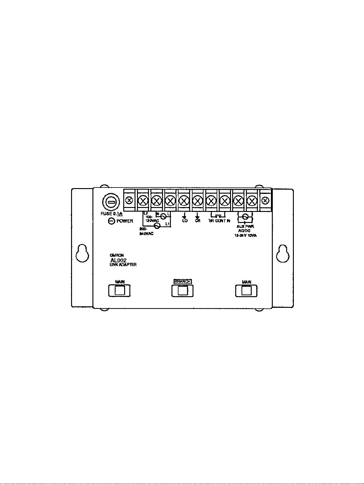
5-2 Link Adapter AL002-(P)E
5-2SectionLink Adapter AL002-(P)E
The
Link Adapter can run on either 100/200 V
input
terminals should be shorted across when not being
usage of the repeater input, refer to
power supplies, see
2-5 Backup Power Supply
2-6 Link Adapter Repeater Input
AC or 12-24 VAC/DC. The repeater
used. For details on the
. For backup
.
25
Page 35

5-3 Link Adapter AL004-(P)E
0 V
External
line
Available
(Yes)
Not
available
(No)
5-3SectionLink Adapter AL004-(P)E
Terminating resistance
selector switch
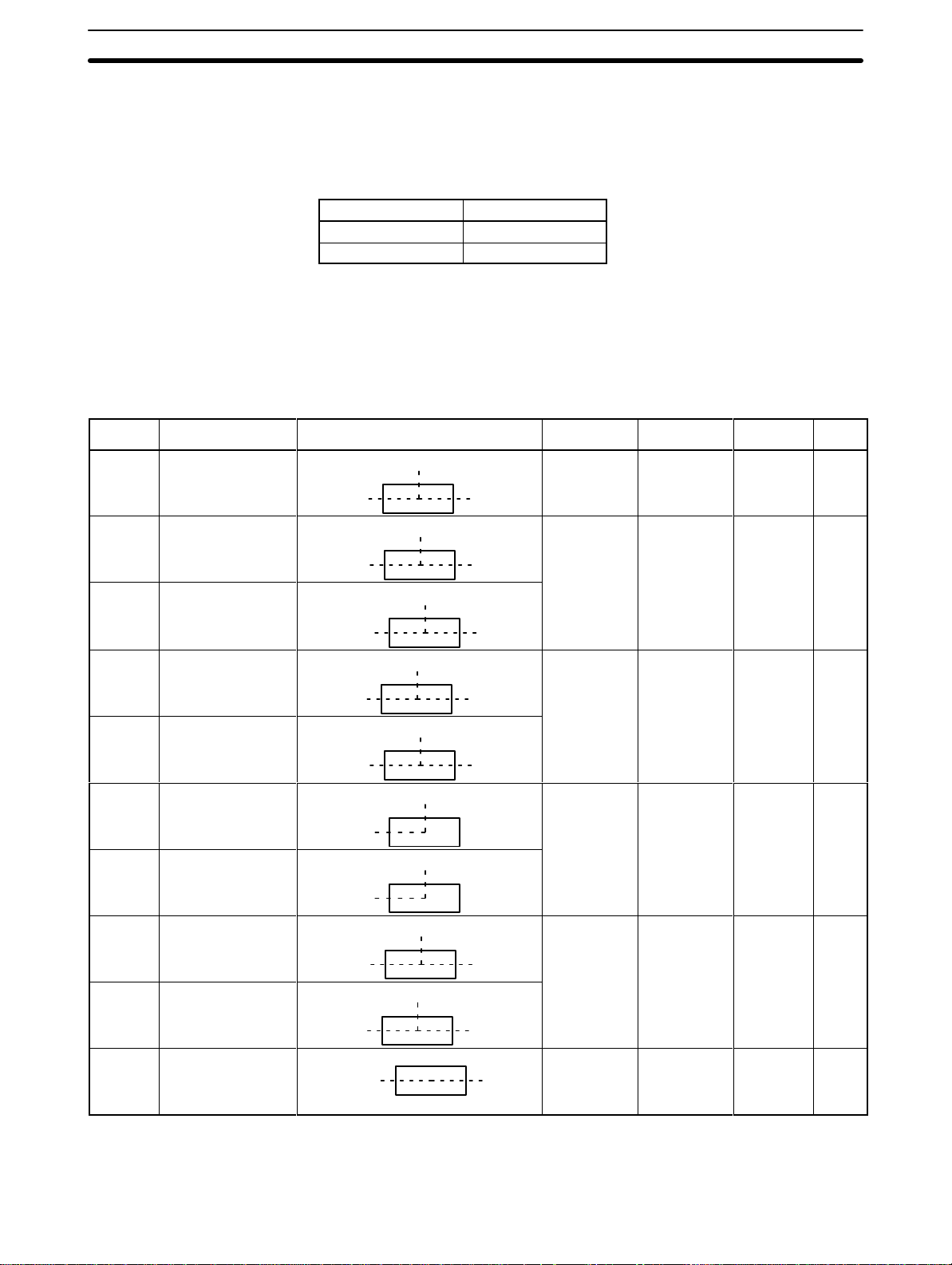
Switch Settings
CTS Selector
Termination Resistance
26
Set
to 0 V to have the clear-to-send (CTS)
signal always ON. Set to external to
receive an external CTS signal.
When
set to ON, connects the built-in termination resistance (220 Ω); when set
to
OFF
, disconnects it. T
urn ON the termination resistance of the last Link Adapt
er at each end of each Subsystem.
-
Page 36

5-4 Link Adapter AL005-(P)E
5-4SectionLink Adapter AL005-(P)E
Use
FC connecters for AGF (crystal optical fiber;) cable. AGF connecters have
fixed
positions for reception and transmission, so be careful to connect them
rectly.
The
Link Adapter can operate on either 100/200 V
tails on auxiliary power supplies, see
2-5 Backup Power Supply
AC or 12-24 V
AC/DC. For de
.
cor
27
-
-
Page 37

5-5 Link Adapter AL006-(P)E
5-5SectionLink Adapter AL006-(P)E
28
Use
FC connecters for AGF cable. AGF connecters have fixed positions for re
ception and transmission, so be careful to connect them correctly.
This Link Adapter can operate on either 100/200 VAC or 12-24 VAC/DC. The
repeater
tails
details on auxiliary power supplies, see
input terminals should be shorted across when not being used. For de
on how to use the repeater input, see
2-6 Link Adapter
2-5 Backup Power Supply
Repeater Input
.
. For
-
-
Page 38

5-6 Link Adapter AL007-P
5-6SectionLink Adapter AL007-P
The AL007-P is used exclusively for Wired Remote I/O Systems. It cannot be
used
in Optical Remote I/O Systems, nor can it be used in combination with an
AL002-(P)E.
29
Page 39

Appendix A
Standard Models
Name Specifications Model Number
Optical (APF/PCF) (3 connectors) 3G2A9-AL002-PE
RS-422 (2 connectors), RS-232C (1 connector) 3G2A9-AL003-E
Optical (APF/PCF), RS-422, RS-232C (1 conn. each) 3G2A9-AL004-PE
Optical (APF/PCF), (AGF) (1 connector each) 3G2A9-AL005-PE
Optical (APF/PCF) (1 connector), (AGF) (2 connectors) 3G2A9-AL006-PE
Link Adapter RS-422 (3 connectors) 3G2A9-AL001
Optical (PCF) (3 connectors) 3G2A9-AL002-E
Optical (PCF), RS-422, RS-232C (1 connector each) 3G2A9-AL004-E
Optical (PCF), (AGF) (1 connector each) 3G2A9-AL005-E
Optical (PCF) (1 connector), (AGF) (2 connectors) 3G2A9-AL006-E
Optical (APF/PCF) (1 connector), (AGF) (2 connectors) B500-AL007-P
0.1 m w/connector 3G5A2-0F011
1 m w/connector 3G5A2-0F101
2 m w/connector 3G5A2-0F201
3 m w/connector 3G5A2-0F301
Optical fiber cable 5 m w/connector Ambient temperature: 3G5A2-0F501
(indoor) (PCF) 10 m w/connector -10°
20 m w/connector 3G5A2-0F211
30 m w/connector 3G5A2-0F311
40 m w/connector 3G5A2-0F411
50 m w/connector 3G5A2-0F511
Optical fiber cable (PCF)
(for indoors or outdoors) (Order in units of 10 m.) -10°
Optical fiber cable (APF) Cable only; for 5 m to 100 m, order in multiples of 5 m; or in
Optical fiber cable set (APF) 1 m cable with connector at each end (connector A) 3G5A2-PF101
Optical connector A 2 optical connectors (brown); for APF cable 10 m max. 3G5A2-CO001
Optical connector B 2 optical connectors (black); for APF cable 8 to 20 m long 3G5A2-CO002
Repeater Unit To use more than 32 Optical Transmitting I/O Units in se-
10 to 500 m
501 to 800 m
(Order in units of 10 m) 0°
multiples of 200 m or 500 m.
ries, 85 to 250 VAC
to 70
°C 3G5A2-0F111
Ambient temperature:
to 70
°C 3G5A2-OF002
Ambient temperature:
to 55
°C (Must not be ex-
posed to direct sunlight)
3G5A2-PF002
3G5A2-RPT01-P
(APC/PCF)
3G5A2-RPT01 (PCF)
Note Optical
fiber cable is not easily connected. Figure
connections and extensions.
Crystal Optical Fiber Cable
Crystal
GI 50/25; connector: FC)
optical fiber cable is not available from OMRON. Order it directly from the manufacturer
in extra length when determining cable lengths for making
. (Applicable fiber:
31
Page 40

Wire Cable
We recommend the following cables for RS-422, RS-232C, and RS-485 connections.
Cable type Recommended Cable
RS-232C CO-DS-IREVV-SX-10P x 0.18 mm2 (Hitachi Cable)
RS-422 CO-HC-ESV-3P x 7/0.2 (Hirakawa Cable)
RS-485 VCTF 0.75 x 2C (JIS)
Appendix AStandard Models
32
Page 41

Index
A
application precautions,
C
cable connectors
optical fiber cable,
soldering,
wire cable,
wiring,
CTS selector,
H
host computers, ,
connecting to, ,
Host Link Systems, , , ,
optical,
wired,
I
P
PC Link Systems, , , ,
power interruption,
backup power supply, ,
bypassing malfunctioning Unit, ,
power supply,
specifications, ,
precautions,
applications,
general,
operating environment,
safety,
R
Remote I/O Master Units, ,
Remote I/O Slave Units, ,
Remote Terminals,
repeater input, , ,
Repeater Units, , , ,
I/O Link Units, ,
installation precautions,
O
operating environment precautions,
optical fiber cable,
applicable Link Adapters,
branching,
cable length, ,
converting to wire cable, , , ,
crystal optical fiber, , ,
calculating transmission distance, ,
connectors, ,
specifications,
handling,
Repeater Units,
types,
Optical Host Link Units,
optical links between Units, ,
Optical Remote I/O Systems, , ,
Optical Slave Racks, ,
Optical Transmitting I/O Units, , ,
S
safety precautions. See precautions
specifications, ,
switch settings,
T
termination resistance,
W
wire cable,
branching,
cable length,
converting to optical fiber cable, , , , ,
RS-422 or RS-232C, ,
RS-485,
specifications,
Wired Remote I/O Systems, , , ,
33
Page 42

Revision History
A manual revision code appears as a suffix to the catalog number on the front cover of the manual.
Cat. No. W123-E1-3
Revision code
The following table outlines the changes made to the manual during each revision. Page numbers refer to
previous version.
Revision code Date Revised content
1 1990 Original production
2 September 1990 First production in Interleaf. Put into current manual format.
Changes: Added 3G2A9-AL003-E to Standard Model list
Minor prose changes for readability
2A September 1995 Page 3: The table row containing AL004-PE corrected.
3 June 1999 Manual format changed.
Page 3: Supply voltage and operating voltage range information changed for
AL004-PE/E.
Page 24:
Page 26: Switch information added to the upper-left diagram.
Grounding information added to the pin number diagram.
Precautions
section added before Section 1.
35
Page 43

Authorized Distributor:
Cat.
No. W123-E1-3
Note: Specifications subject to change without notice.
Printed in Japan
 Loading...