

Page 1
1
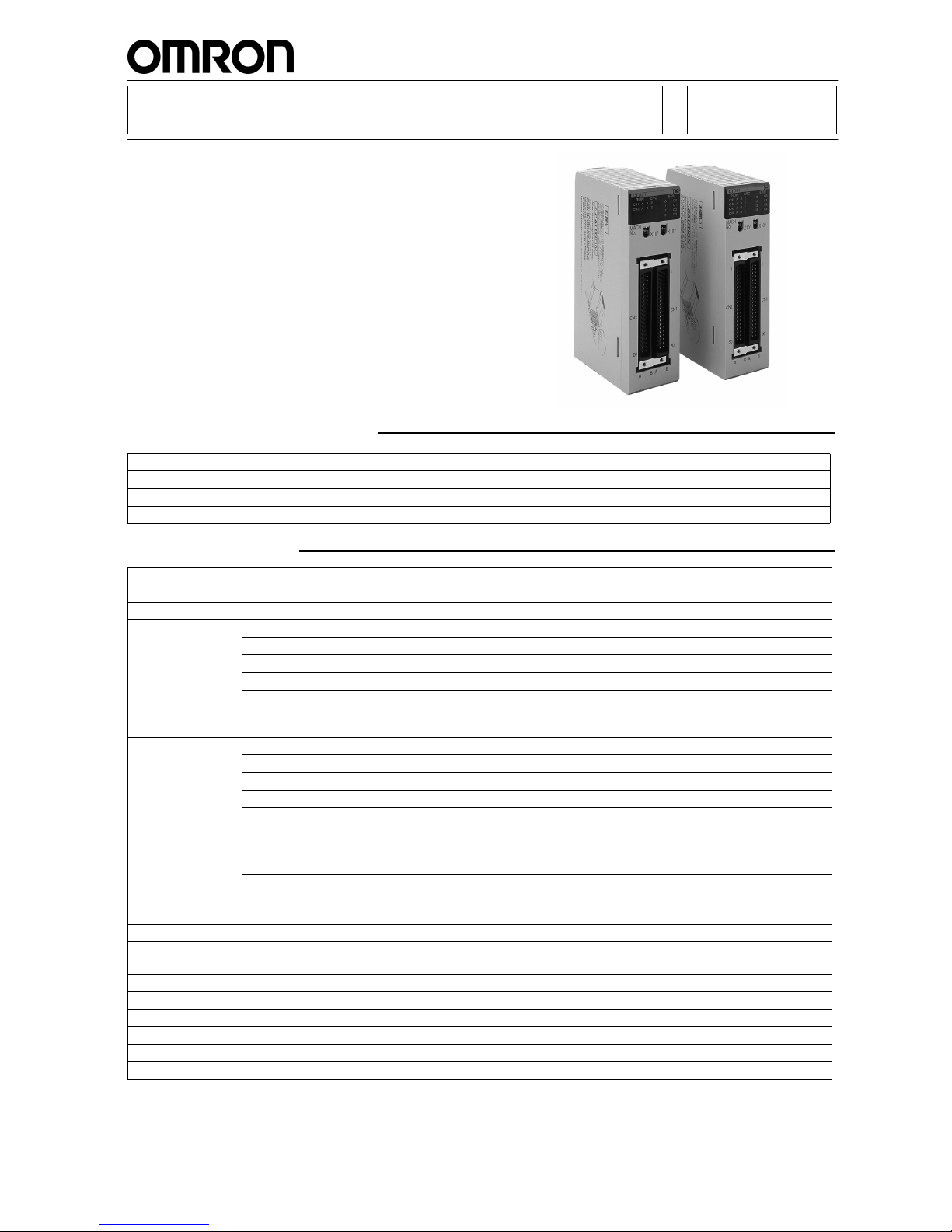
CS1W-CT021/CT041
2/4 channels High Speed Counter Units
2 or 4 Channels High Speed Counter Units for
CS1 PLC.
Frequency up to 500 kHz, closed loop response
time as low as 0.1 ms.
4 Digital In, 4 Digital Out and 28 soft outputs can
be freely allocated to counter channels.
Interrupt functions built in.
Simple mode or Configurable Mode.
Three counter types: simple, linear and circular.
Four counter signal levels: 5 Vdc, 12 Vdc, 24 Vdc
and Line Driver.
On the fly configuration changes.
Ordering Information
Specifications
Product Code Description
CS1W-CT021 2 channels High Speed Counter Unit
CS1W-CT041 4 channels High Speed Counter Unit
W902-E2-1 CS1W-CT021/CT041 High Speed Counter Units Operation Manual
Item CS1W-CT021 CS1W-CT041
Number of counters
24
Operation modes
Simple counter, circular counter, linear counter
Count inputs Input signals
Phase A and B
Signal levels
RS-422 line driver signal, 5, 12 or 24 Vdc selectable
Types of inputs
Phase Differential; Up/Down; Pulse & Direction
Counting rate
500 kHz max.
Others
The multiple function (x1, x2 or x4) can be selected for phase differential input
Counter inputs are insulated from each other and from the Digital inputs, insulated from
the I/O-bus, and also reverse polarity protected
External inputs Input signal
Input Z
Signal levels
RS-422 line driver signal, 5, 12 or 24 Vdc selectable
Input signal
4 Inputs (I0, I1, I2 and I3), that can be freely allocated to any counter
Signal levels
24 Vdc
Others
External inputs are insulated from each other, insulated from the I/O-bus, and also reverse polarity protected.
External outputs Output signal
4 outputs, NPN / PNP selectable
Signal levels
12 - 24 Vdc
Switching capacity
46 mA at 10.2 Vdc to 100 mA at 26.4 Vdc; 400 mA max per common
Others
Digital Outputs are insulated from the I/O-bus
Output pattern include these 4 Digital Outputs and 28 soft outputs
Current consumption (5V via backplane)
360 mA 450 mA
Number of words allocated
40 CIO-words. First word allocated = CIO2000 + (Nx10)
400 DM-words. First word allocated = D20000 + (Nx100)
Storage temperature
-20 to + 75 °C
Ambient temperature
0 to + 55 °C
Ambient humidity
10 to 90 % (non-condensing)
EMC compliance
EN 50081-2, EN 61131-2
Dimensions (mm)
35 x 130 x 100 (W x H x D)
Weight
245 g
EU: www.elinco.eu
RUS: www.elinc.ru
Sales, service
Page 2
2
CS1W-CT021/CT041CS1W-CT021/CT041
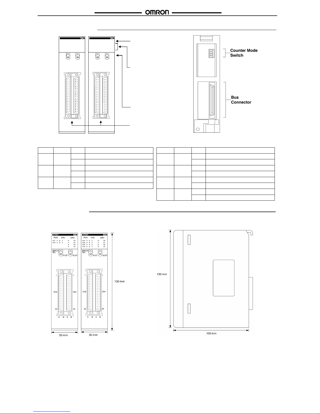
Nomenclature
Dimensions
Note
All units are in millimeters unless otherwise indicated.
Front View Side View
Unit status indicators Counter channel status
Name Colour State Unit status Name Colour State Counter channel status
RUN green on Normal operation CH1, 2
CH3, 4
green on Counter running / Gate open
off Initialisation error off Counter not running / Gate closed
ERC red on Unit error(check CIO n+17, n+18) A, B, Z yellow on Physical input A, B, Z turned on
off Unit has no errors off Physical input A, B, Z turned off
ERH red on CS1-CPU Unit error I0, I1
I2, I3
yellow on Digital Input turned on
off CS1-CPU Unit has no errors off Digital Input turned off
O0, O1
O2, O3
yellow on Digital Output turned on
off Digital Output turned off
Unit Status
indicators
RUN (green)
ERC (red)
ERH (red)
Counter Channel status
indicators (all yellow):
Counter Inputs A, B, Z
Digital Inputs I0, I1, I2, I3
Digital Outputs O0, O1, O2,
O3
Counter Gate CH1, 2, 3, 4
(green)
CT041
No.
X10
1
MACH
X10
0
RUN
CH1
CH2
CH3
CH4
ERC
ERH
A
A
A
A
B
B
B
B
Z
Z
Z
Z
I0
I1
I2
I3
O0
O1
O2
O3
CT021
No.
X10
1
MACH
X10
0
RUN
CH1
CH2
ERC
ERH
AABBZ
ZI0I1
I2
I3
O0
O1
O2
O3
CN1CN2
CN1CN2
A B A B
1
20
1
20
A B A B
1
20
1
20
Machine Number (N)
rotary switches:
Set between 00-92
(93-99 is invalid)
Two 40-pins connectors:
CN1 & CN2
Page 3
3
CS1W-CT021/CT041CS1W-CT021/CT041
InstallationInstallation
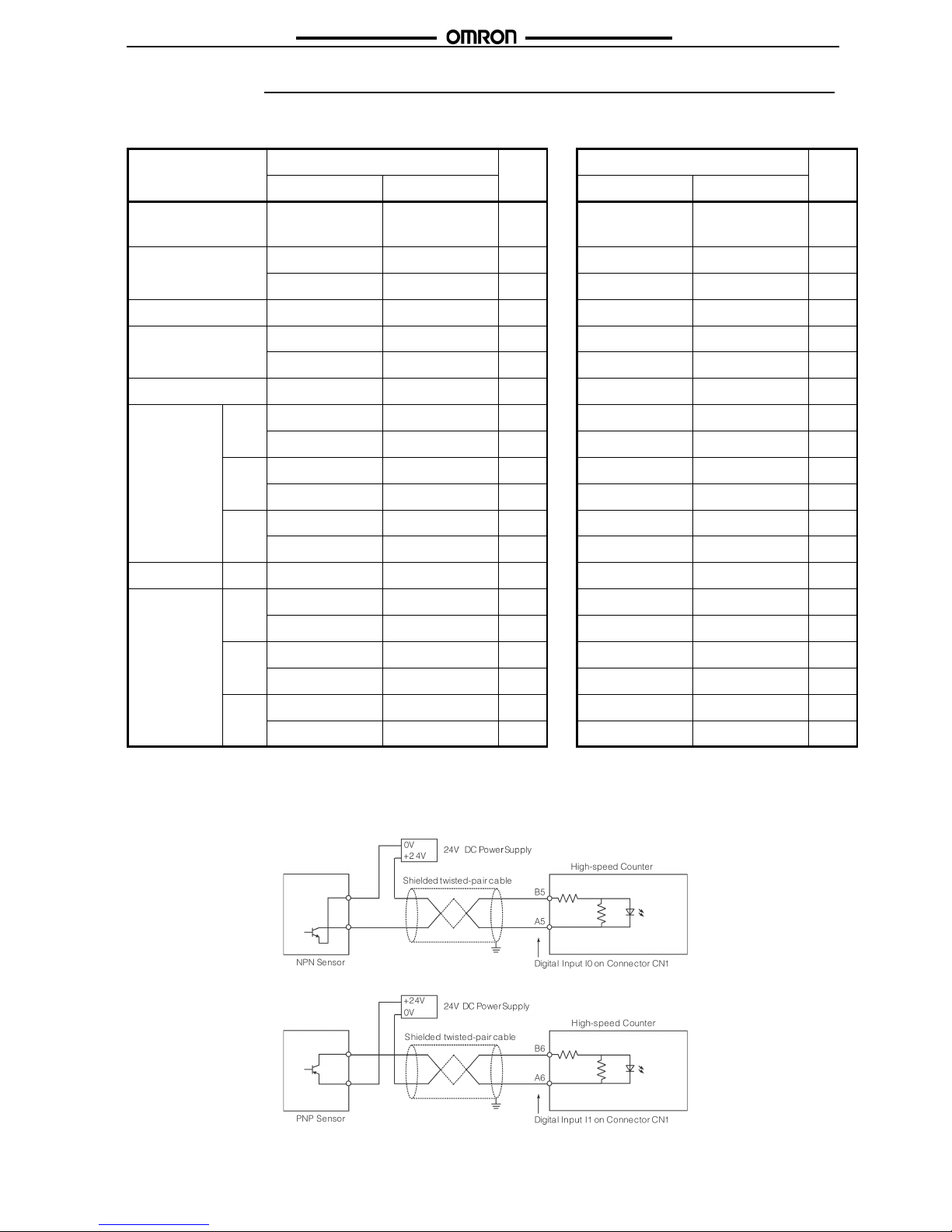
Connector (CN1 and CN2) Pin-layout
Use the following table to make connections directly to the soldering terminals of the connector jack(s):
Note
*CS1W-CT041 High-speed Counter Unit only.
PS = Power Supply Lines, O0-O3 = Digital Outputs, I0-I3 = Digital Inputs, CH1-CH4 = Counter 1 - Counter 4, LD = Line Driver Signals
Digital I/O Circuit Configurations
24 VDC NPN Sensor
24 VDC PNP Sensor
Item Connector 2 (CN2) Pin
No.
Connector 1 (CN1) Pin
No.
Row A Row B Row A Row B
Power Supply (to
feed the outputs)
-PS: 0V +PS: 12 to 24V
1
-PS: 0V +PS:12 to 24V
1
Digital Outputs
[0-3] (NPN/PNP)
O2: NPN O2: PNP
2
O0: NPN O0: PNP
2
O3: NPN O3: PNP
3
O1: NPN O1: PNP
3
Spare 4 4
Digital Inputs
[0-3]
I2: 0V I2: 24V
5
I0: 0V I0: 24V
5
I3: 0V I3: 24V
6
I1: 0V I1: 24V
6
Spare 7 7
Counter 1 &
Counter 2
A
CH2: LD- / 0V CH2: LD+
8
CH1: LD- / 0V CH1: LD+
8
CH2: 12V CH2: 24V
9
CH1: 5V CH1: 24V
9
B
CH2: LD- / 0V CH2: LD+
10
CH1: LD- / 0V CH1: LD+
10
CH2: 12V CH2: 24V
11
CH1: 5V CH1: 24V
11
Z
CH2: LD- / 0V CH2: LD+
12
CH1: LD- / 0V CH1: LD+
12
CH2: 12V CH2: 24V
13
CH1: 5V CH1: 24V
13
Spare 14 14
Counter 3 &
Counter 4*
A
CH4: LD- / 0V CH4: LD+
15
CH3: LD- / 0V CH3: LD+
15
CH4: 12V CH4: 24V
16
CH3: 5V CH3: 24V
16
B
CH4: LD- / 0V CH4: LD+
17
CH3: LD- / 0V CH3: LD+
17
CH4:12V CH4: 24V
18
CH3: 5V CH3: 24V
18
Z
CH4: LD- / 0V CH4: LD+
19
CH3: LD- / 0V CH3: LD+
19
CH4:12V CH4: 24V
20
CH3: 5V CH3: 24V
20
Page 4

4
CS1W-CT021/CT041CS1W-CT021/CT041
Counter Input Configurations
5/12/24 VDC NPN Open Collector
5/12/24 VDC PNP Open Collector
Page 5

5
CS1W-CT021/CT041CS1W-CT021/CT041
Line Driver (RS422)
Operation
Machine Number Switch
Note
* For the CS1W-CT021/041 40 CIO-words and 400 DM-words are allocated.
Counter Type Switch
Note
* Circular and Linear Counter are fully DM-configurable. Refer to Operation Manual (Cat. No. W902-E2-1).
Name Function
MACHINE No. Sets the Machine Number* (00 - 92).
• Machine Numbers 93-99 cannot be set and will generate an error.
• Make sure each Machine Number is used only once per CS1-CPU.
Be sure to turn off the power to the Unit before setting the Machine Number.
Name Function
Counter Type: Sets the Counter Type of every Counter (the switch is located at the back of the Unit):
Pin Position Type
1 on Circular/Linear Counter*
off Simple Counter
2 on Circular/Linear Counter*
off Simple Counter
3 on Circular/Linear Counter*
off Simple Counter
4 on Circular/Linear Counter*
off Simple Counter
No.
X10
1
MACH
X10
0
1234
O
N
Page 6

6
CS1W-CT021/CT041CS1W-CT021/CT041
Operating Simple Counter via CIO
Note
* n = CIO2000 + (Nx10), ** CS1W-CT041 only,
*** ON for one PLC-scan
CX-Programmer Support Software or a Programming Console
can be used to (DM-) configure Circular and Linear Counters.
Refer to Operation Manual (Cat. No. W902-E2-1).
Internal Circuit Configuration
Digital Input Counter Input
Word* (output) Bit Function
General
n
00-03
Manual Output Control
Digital Outputs (On=1, Off=0)
15 Automatic (=0) / Manual (=1)
n+1 00 Read (next) Error (0Æ1)
Counter 1
n+2
00 Open Gate (0Æ1)
01 Close Gate (0Æ1)
02 Preset (0Æ1)
03 Reset (0Æ1)
04 Capture (0Æ1)
n+3, n+4 00-15
Preset Value
(80000000
H
- 7FFFFFFFH)
Counter 2
n+5 See n+2
n+6, n+7 See n+3, n+4
Counter 3**
n+8 See n+2
n+9, n+10 See n+3, n+4
Counter 4**
n+11 See n+2
n+12, n+13 See n+3, n+4
Word* (input) Bit Function
General
n+14, n+15 00-15 Output Status (On=1, Off=0)
n+16 00-03 Input Status (On=1, Off=0)
n+17, n+18 00-15 Error Code
n+19 00 Global Error Indication
02 Data Transfer Busy
03 Data Transfer Completed
Counter 1
n+22, n+23 00-15
Counter Value
(80000000
H
- 7FFFFFFFH)
n+24 00 Counter Overflow (=1)
01 Counter Underflow (=1)
02 Counter running/Gate Open (=1)
03 Counting Direction (up=1/down=0)
04 Preset Activated (=1)***
05 Reset Activated (=1)***
06 Capture Activated (=1)***
07 Z-signal Activated (=1)***
15 Simple Counter selected (=1)
Counter 2
n+27, n+28 See n+22, n+23
n+29 See n+24
Counter 3**
n+32, n+33 See n+22, n+23
n+34 See n+24
Counter 4**
n+37, n+38 See n+22, n+23
n+39 See n+24
Page 7

7
CS1W-CT021/CT041CS1W-CT021/CT041
Digital Output
Accessories
Terminal block types
XW2B-40G4 XW2B-40G5
I/O points
32 32
Screw size
M2.4 M3.5
Compatible cables
XW2Z-050B (0.5 m), XW2Z-100B (1 m), XW2Z-150B (1.5 m),
XW2Z-300B (3 m), XW2Z-200B (2 m), XW2Z-500B (5m)
Page 8

8
CS1W-CT021/CT041CS1W-CT021/CT041
In the interest of product improvement, specifications are subject to change without notice.
ALL DIMENSIONS SHOWN ARE IN MILLIMETERS.
To convert millimeters into inches, multiply by 0.03937. To convert grams into ounces, multiply by 0.03527.
Cat. No. R076-E2-01
OMRON EUROPE B.V.
Wegalaan 67-69
2132 JD Hoofddorp
The Netherlands
Phone: +31 23 568 13 00
Fax: +31 23 568 13 88
Printed in the Netherlands
 Loading...