

Omron CP1E-N40DR-A, CP1E-E20DR-A DATASHEET

New Product
SYSMAC CP-series CP1E CPU Units
CP1E-E@@D@-@
CP1E-N@@D@-@/NA20D@-@
The CP1E Package PLCs: Economical, Easy to use, and Efficient
■ The E-type Basic CPU Units provide cost
performance and easy application with only basic
functionality.
■ The N and NA-types Application CPU Units support
Programmable Terminal connection, position control,
and inverter connection
CP1E-E20DR-A
CP1E-N40DR-A
Features
• Programming, setting, and monitoring with CX-Programmer.
• Easy connection with computers using commercially available USB cables
• With E30/40, N30/40/60 or NA20 CPU Units, Add I/O by Connecting Expansion I/O Units.
• With E30/40, N30/40/60 or NA20 CPU Units, Add Analog I/O or Temperature Inputs by Connecting Expansion Units.
• Quick-response inputs
• Input interrupts
• Complete High-speed Counter Functionality.
• Versatile pulse control for Transistor Output for N14/20/30/40/60 or NA20 CPU Units.
• PWM Outputs for Transistor Output for N14/20/30/40/60 or NA20 CPU Units.
• Built-in RS-232C Port for N/NA-type CPU Units.
• Mounting Serial Option Boards to N30/40/60 or NA20 CPU Units.
• Built-in analog I/O, two inputs and one output, for NA-type CPU Units.
1
CP1E-E@@D@-@ CP1E-N@@D@-@/NA20D@-@
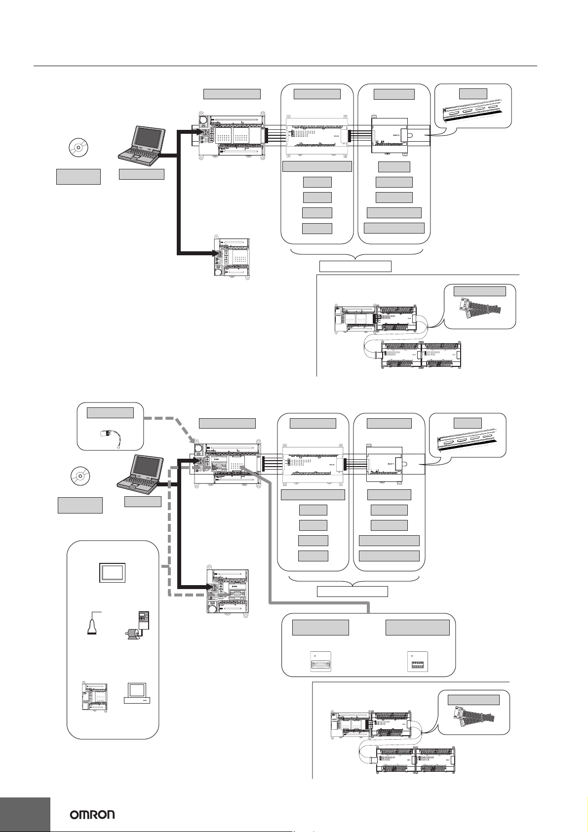
System Configuration
Basic System Configuration Using an E-type CPU Unit
Support Software
CX-Programmer
Personal computer
IBM PC/AT or equivalent
CP1E CPU Unit Expansion I/O Units Expansion Units
CP1E-E30DR-A
CP1E-E40DR-A
CP1E-E10D@-@
CP1E-E14DR-A
CP1E-E20DR-A
20 or 40 I/O Points
8 inputs
8 outputs
16 outputs
32 outputs
Up to 3 Units can be connected
When a two level layout is created by expansion and distance is required
CP1E CPU Unit
Analog I/O
Analog inputs
Analog outputs
Temperature sensors
CompoBus/S I/O Link Unit
Expansion Units and
Expansion I/O Units
DIN Track
I/O Connecting Cable
CP1W-CN811
Basic System Configuration Using an N/NA-type CPU Unit
Battery
Support Software
CX-Programmer
(NT Link/HOST Link)
General component
(No-protocol mode)
CP-series PLC or
CJ1M PLC
(Serial PLC Link)
CP1W-BAT01
Built in RS-232C
Programmable
Terminal (PT)
(Modbus-RTU)
Personal computer
IBM PC/AT or
equivalent
Inverter
Host computer
(Host Link)
CP1E CPU Unit
CP1E-N30D-
CP1E-N40D-
CP1E-N60D-
CP1E-NA20D-
CP1E-N14D-
CP1E-N20D-
Expansion I/O Units Expansion Units
20 or 40 I/O Points
8 inputs
8 outputs
16 outputs
32 outputs
Up to 3 Units can be connected
RS-232C Option Board
CP1W-CIF01
COMM
When a two level layout is created by expansion and distance is required
CP1E CPU Unit
Temperature sensors
CompoBus/S I/O Link Unit
Or
DIN Track
Analog I/O
Analog inputs
Analog outputs
*Neither the CP1W-DAM01 LCD Option Board nor the CP1W-CIF41
Ethernet Option Board can be used.
RS-422A/485 Option Board
CP1W-CIF11
CP1W-CIF12
COMM
Expansion Units and
Expansion I/O Units
I/O Connecting Cable
CP1W-CN811
2
CP1E-E@@D@-@ CP1E-N@@D@-@/NA20D@-@
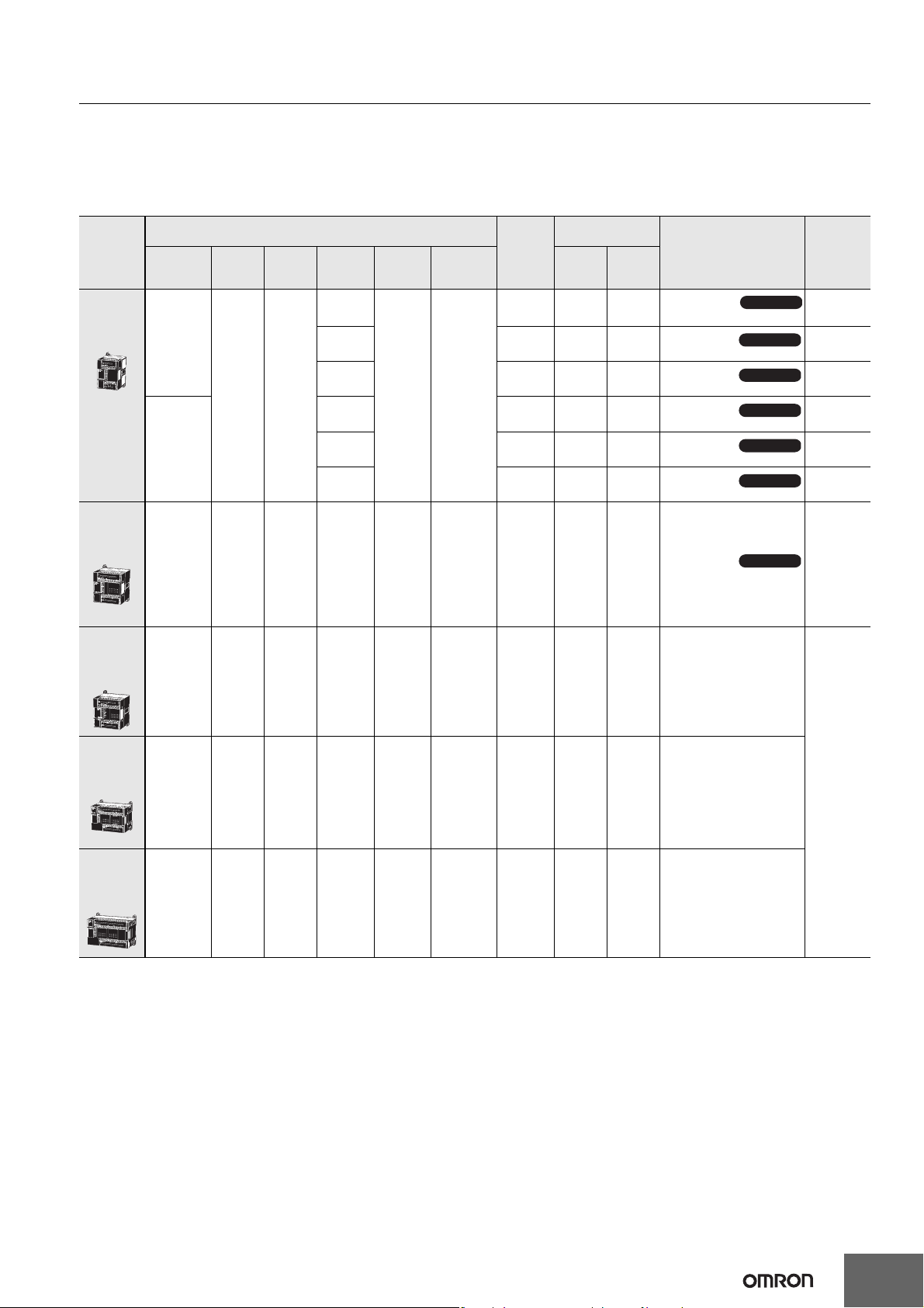
Ordering Information
International Standards
• The standards are abbreviated as follows: U: UL, U1: UL (Class I Division 2 Products for Hazardous Locations), C: CSA, UC: cULus,
UC1: cULus (Class I Division 2 Products for Hazardous Locations), CU: cUL, N: NK, L: Lloyd, and CE: EC Directives.
• Contact your OMRON representative for further details and applicable conditions for these standards.
E-type CP1E CPU Units (Basic Models)
Current
consumption (A)
Model Standards
5 V 24 V
Available soon
CP1E-E10DR-A
Available soon
CP1E-E10DT-A
Available soon
CP1E-E10DT1-A
Available soon
CP1E-E10DR-D
Available soon
CP1E-E10DT-D
Available soon
CP1E-E10DT1-D
Available soon
CP1E-E14DR-A
Product
name
E-type
CPU Units
with 10 I/O
Points
E-type
CPU Units
with 14 I/O
Points
Power
Supply
100 to 240
VAC
24 VDC
100 to 240
VAC
Specifications
Inputs Outputs
64
8 6 Relay 2K steps 2K words -- 0.16 0.07
Output
Relay
Transistor
(sinking)
Transistor
(sourcing)
Relay -- 0.08 0.04
Transistor
(sinking)
Transistor
(sourcing)
type
Program
capacity
2K
steps
Data
memory
capacity
2K
words
External
power
supply
(24 VDC)
(A)
-- 0.08 0.04
-- 0.11 --
-- 0.11 --
-- 0.11 --
-- 0.11 --
--
--
--
--
--
--
--
E-type
CPU Units
with 20 I/O
Points
E-type
CPU Units
with 30 I/O
Points
E-type
CPU Units
with 40 I/O
Points
100 to 240
VAC
100 to 240
VAC
100 to 240
VAC
12 8 Relay 2K steps 2K words -- 0.17 0.08 CP1E-E20DR-A
18 12 Relay 2K steps 2K words 0.30 0.17 0.07 CP1E-E30DR-A
24 16 Relay 2K steps 2K words 0.30 0.17 0.09 CP1E-E40DR-A
Note: There are no accessories included with E-type CP1E CPU Units. A Battery (CP1W-BAT01) cannot be used.
N, L, CE
3
CP1E-E@@D@-@ CP1E-N@@D@-@/NA20D@-@
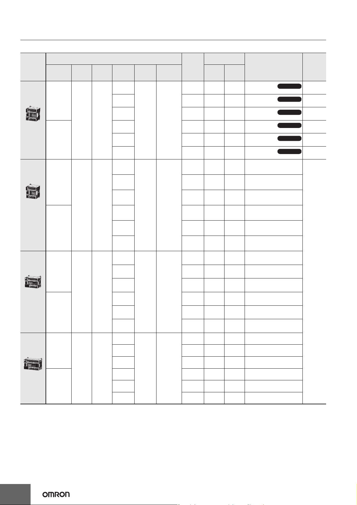
N/NA-type CP1E CPU Units (Application Models)
External
power
supply
(24 VDC)
(A)
-- 0.17 0.07
-- 0.22 0.02
-- 0.22 0.02
-- 0.22 0.02
-- 0.22 0.02
-- 0.18 0.08 CP1E-N20DR-A
-- 0.23 0.02 CP1E-N20DT-A
Product
name
N-type
CPU Units
with 14 I/O
Points
N-type
CPU Units
with 20 I/O
Points
Power
Supply
100 to 240
VAC
24 VDC
100 to 240
VAC
Specifications
Inputs Outputs
86
Output
Relay
Transistor
(sinking)
Transistor
(sourcing)
Relay -- 0.17 0.07
Transistor
(sinking)
Transistor
(sourcing)
Relay
Transistor
(sinking)
type
Program
capacity
8K
steps
Data
memory
capacity
8K
words
Current
consumption (A)
5 V 24 V
Model
CP1E-N14DR-A
CP1E-N14DT-A
CP1E-N14DT1-A
CP1E-N14DR-D
CP1E-N14DT-D
CP1E-N14DT1-D
Available soon
Available soon
Available soon
Available soon
Available soon
Available soon
Standards
--
--
--
--
--
--
N-type
CPU Units
with 30 I/O
Points
N-type
CPU Units
with 40 I/O
Points
24 VDC
100 to 240
VAC
24 VDC
100 to 240
VAC
24 VDC
12 8
18 12
24 16
Transistor
(sourcing)
Relay -- 0.18 0.08 CP1E-N20DR-D
Transistor
(sinking)
Transistor
(sourcing)
Relay
Transistor
(sinking)
Transistor
(sourcing)
Relay -- 0.21 0.07 CP1E-N30DR-D
Transistor
(sinking)
Transistor
(sourcing)
Relay
Transistor
(sinking)
Transistor
(sourcing)
Relay -- 0.21 0.09 CP1E-N40DR-D
Transistor
(sinking)
Transistor
(sourcing)
8K steps 8K words
8K steps 8K words
8K steps 8K words
-- 0.23 0.02 CP1E-N20DT1-A
-- 0.23 0.02 CP1E-N20DT-D
-- 0.23 0.02 CP1E-N20DT1-D
0.30 0.21 0.07 CP1E-N30DR-A
0.30 0.27 0.02 CP1E-N30DT-A
0.30 0.27 0.02 CP1E-N30DT1-A
-- 0.27 0.02 CP1E-N30DT-D
-- 0.27 0.02 CP1E-N30DT1-D
0.30 0.21 0.09 CP1E-N40DR-A
0.30 0.31 0.02 CP1E-N40DT-A
0.30 0.31 0.02 CP1E-N40DT1-A
-- 0.31 0.02 CP1E-N40DT-D
-- 0.31 0.02 CP1E-N40DT1-D
N, L, CE
4
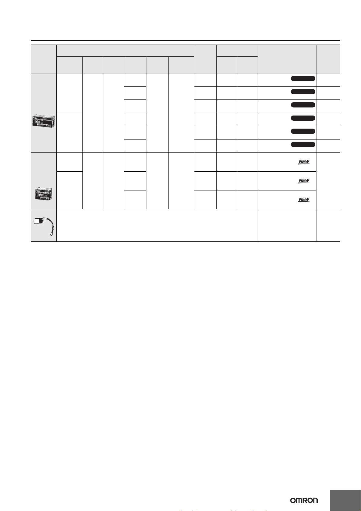
CP1E-E@@D@-@ CP1E-N@@D@-@/NA20D@-@
Product
name
N-type
CPU Units
with 60 I/O
Points
NA-type
CPU Units
with 20 I/O
Points
(Built-in
analog)
Battery Set For N/NA-type CP1E CPU Units
Power
Supply
100 to 240
VAC
24 VDC
100 to 240
VAC
24 VDC
Inputs Outputs
36 24
12
(Built-in
analog
inputs: 2)
Specifications
8
(Built-in
analog
outputs: 1)
External
power
Output
Relay
Transistor
(sinking)
Transistor
(sourcing)
Relay -- 0.21 0.13
Transistor
(sinking)
Transistor
(sourcing)
Relay
Transistor
(sinking)
Transistor
(sourcing)
type
Program
capacity
8K
steps
8K
steps
Data
memory
capacity
8K
words
8K
words
supply
(24 VDC)
(A)
0.30 0.21 0.13
0.30 0.31 0.02
0.30 0.31 0.02
-- 0.31 0.02
-- 0.31 0.02
0.30 0.18 0.11 CP1E-NA20DR-A
-- 0.23 0.09 CP1E-NA20DT-D
-- 0.23 0.09 CP1E-NA20DT1-D
Current
consumption (A)
5 V 24 V
Model
CP1E-N60DR-A
CP1E-N60DT-A
CP1E-N60DT1-A
CP1E-N60DR-D
CP1E-N60DT-D
CP1E-N60DT1-D
Available soon
Available soon
Available soon
Available soon
Available soon
Available soon
Standards
--
--
--
--
--
--
CE
Note: Mount a Battery to an N/NA-type CPU Unit if the data in the following areas must be
backed up for power interruptions.
• DM Area (D) (except backed up words in the DM Area), Holding Area (H), Counter Completion Flags (C),
Counter Present Values (C), Auxiliary Area (A), and Clock Function
(Use batteries within two years of manufacture.)
CP1W-BAT01 CE
Note: There are no accessories included with N/NA-type CP1E CPU Units. RS-232C connectors for the built-in RS-232C port and the Battery
(CP1W-BAT01) are not included.
5

CP1E-E@@D@-@ CP1E-N@@D@-@/NA20D@-@
Options (for CP1E N30/40/60 or NA20 CPU Units)
The Options cannot be used for CP1E N14/20 CPU Units and all E-type CPU Units.
Product name Specifications Model Standards
RS-232C Option Board
RS-422A/485 Option Board
RS-422A/485 Isolated-type
Option Board
Note: It is not possible to use a CP-series Ethernet Option Board (CP1W-CIF41), LCD Option Board (CP1W-DAM01), or Memory Card (CP1W-
ME05M) with a CP1E CPU Unit.
Programming Devices
Product name
FA Integrated Tool Package
CX-One Lite
Ver.4.@
CX-One FA Integrated Tool
Package Ver. 4.@
Note: The E20, E30, E40, N20, N30 and N40 CPU Units are supported by CX-Programmer version 8.2 or higher.
The E10, E14, N14, N60, and NA20 CPU Units are supported by CX-Programmer version 9.03 or higher.
When Micro PLC Edition CX-Programmer is used, you need version 9.03 or higher.
* Site licenses are available for the CX-One (3, 10, 30 or 50 licenses).
One RS-232C Option Board can be
mounted to the Option Board slot.
For CP1E N30/40/60 or NA20 CPU
Units only.
One RS-232C connector is included.
One RS-422A/485 Option Board can be
mounted to the Option Board slot.
For CP1E N30/40/60 or NA20 CPU
Units only.
Specifications
CX-One Lite is a subset of the complete CX-One package that
provides only the Support Software required for micro PLC
applications.
CX-One Lite runs on the following OS.
Windows 2000 (Service Pack 4 or higher), XP, Vista, or 7
(except 64-bit edition)
CX-One Lite Ver. 4.@ includes Micro PLC Edition CXProgrammer Ver.9.@.
CX-One is a package that integrates the Support Software for
OMRON PLCs and components. CX-One runs on the
following OS.
OS: Windows 2000 (Service Pack 4 or higher), XP, Vista, or 7
(except 64-bit edition)
CX-One Ver. 4.@ includes CX-Programmer Ver. 9.@.
CP1W-CIF01
CP1W-CIF11
CP1W-CIF12 N, L, CE
Number of
licenses
1 license CD
CD
1 license *
DVD
Media
UC1, N, L, CE
Model Standards
CXONE-LT01C-V4
CXONE-AL01C-V4
CXONE-AL01D-V4
--
--
The following tables lists the Support Software that can be installed from CX-One
Support Software in CX-One
Micro PLC Edition CX-Programmer Ver.9.@ Yes No CX-Drive Ver.1.@ Yes Yes
CX-Programmer Ver.9.@ No Yes CX-Process Tool Ver.5.@ No Yes
CX-Integrator Ver.2.@ Yes Yes Faceplate Auto-Builder for NS Ver.3.@ No Yes
Switch Box Utility Ver.1.@ Yes Yes CX-Designer Ver.3.@ Yes Yes
CX-Protocol Ver.1.@ No Yes NV-Designer Ver.1.@ Yes Yes
CX-Simulator Ver.1.@ Yes Yes CX-Thermo Ver.4.@ Yes Yes
CX-Position Ver.2.@ No Yes CX-ConfiguratorFDT Ver.1.@ Yes Yes
CX-Motion-NCF Ver.1.@ No Yes CX-FLnet Ver.1.@ No Yes
CX-Motion-MCH Ver.2.@ No Yes Network Configurator Ver.3.@ Yes Yes
CX-Motion Ver.2.@ No Yes CX-Server Ver.4.@ Yes Yes
CX-One Lite
Ver.4.@
CX-One
Ver.4.@
Support Software in CX-One
CX-One Lite
Ver.4.@
CX-One
Ver.4.@
Note: For details, refer to the CX-One Catalog (Cat. No. R134).
6

CP1E-E@@D@-@ CP1E-N@@D@-@/NA20D@-@
Expansion I/O Units and Expansion Units (for CP1E E30/40, N30/40/60, or NA20 CPU Units)
CP1E E10/14/20 or N14/20 CPU Units do not support Expansion I/O Units and Expansion Units.
Current
consumption (A)
5 V 24 V
Model Standards
Unit type Product name
Input Unit
Specifications
Inputs Outputs
8----0.018--CP1W-8ED
Output
type
CP1W
Expansion I/O
Units
CP1W
Expansion
Units
Output Units
I/O Units
Analog Input Unit
Analog Output Unit
Analog I/O Unit
Temperature
Sensor Unit
CompoBus/S
I/O Link Unit
Relay 0.026 0.044 CP1W-8ER
-- 8
-- 16
-- 32
12 8
24 16
4 analog inputs
Input range: 0 to 5 V, 1 to 5 V, 0 to 10 V,
0 to 20 mA, or 4 to 20 mA.
Resolution: 1/6000
4 analog outputs
Output range: 0 to 5 V, 1 to 5 V, 0 to 10 V,
0 to 20 mA, or 4 to 20 mA.
Resolution: 1/6000
2 analog inputs and 1 analog output
I/O range: 0 to 5 V, 1 to 5 V, 0 to 10 V,
0 to 20 mA, or 4 to 20 mA.
Resolution: 1/6000
2 temperature sensor inputs
Sensor type: Thermocouple (J or K)
4 temperature sensor inputs
Sensor type: Thermocouple (J or K)
2 temperature sensor inputs
Sensor type: Platinum resistance thermometer
4 temperature sensor inputs
Sensor type: Platinum resistance thermometer
CompoBus/S slave
8 inputs and 8 outputs
(Pt100 or JPt100)
(Pt100 or JPt100)
Transistor
(sinking)
Transistor
(sourcing)
Relay 0.042 0.090 CP1W-16ER
Transistor
(sinking)
Transistor
(sourcing)
Relay 0.049 0.131 CP1W-32ER
Transistor
(sinking)
Transistor
(sourcing)
Relay 0.103 0.044 CP1W-20EDR1
Transistor
(sinking)
Transistor
(sourcing)
Relay 0.080 0.090 CP1W-40EDR
Transistor
(sinking)
Transistor
(sourcing)
±10 V,
±10 V,
±10 V,
0.075 -- CP1W-8ET
0.075 -- CP1W-8ET1
0.076 -- CP1W-16ET
0.076 -- CP1W-16ET1
0.113 -- CP1W-32ET
0.113 -- CP1W-32ET1
0.130 -- CP1W-20EDT
0.130 -- CP1W-20EDT1
0.160 -- CP1W-40EDT
0.160 -- CP1W-40EDT1
0.100 0.090 CP1W-AD041
0.080 0.124 CP1W-DA041
0.083 0.110 CP1W-MAD11
0.040 0.059 CP1W-TS001
0.040 0.059 CP1W-TS002
0.054 0.073 CP1W-TS101
0.054 0.073 CP1W-TS102
0.029 -- CP1W-SRT21
U, C, N, L, CE
N, L, CE
N, L, CE
U, C, N, L, CE
N, L, CE
UC1, N, L, CE
U, C, N, L, CE
I/O Connecting Cable
Product name Specifications Model Standards
I/O Connecting Cable
Note: An I/O Connecting Cable (approx. 6 cm) for horizontal connection is provided with CP1W Expansion I/O Units and Expansion Units.
80 cm (for CP1W Expansion I/O Units and Expansion Units)
Only one I/O Connecting Cable can be used in each PLC.
CP1W-CN811 UC1, N, L, CE
7

CP1E-E@@D@-@ CP1E-N@@D@-@/NA20D@-@
General Specifications
Type AC power supply models DC power supply models
Model CP1E-@@@D@-A CP1E-@@@D@-D
Enclosure Mounted in a panel
CPU Unit with 10 I/O points (CP1E-E10D@-@): 90mm *1 ×85mm *2 × 66 mm
CPU Unit with 14 or 20 I/O points (CP1E-@14D@-@/@20D@-@): 90mm *1 × 85mm *2 × 86 mm
Dimensions (H × D × W)
Weight
Supply voltage 100 to 240 VAC 50/60 Hz 24 VDC
Operating voltage
range
Power consumption
Electrical
specifications
Application
environment
Terminal block Fixed (not removable)
Terminal screw size M3
Applicable standards Conforms to EC Directive
Grounding method Ground to 100 Ω or less.
Inrush current
External power supply
*3
Insulation resistance
Dielectric strength
Power OFF detection
time
Ambient operating
temperature
Ambient humidity 10% to 90%
Atmosphere No corrosive gas.
Ambient storage
temperature
Altitude 2,000 m max.
Pollution degree 2 or less: Conforms to JIS B3502 and IEC 61131-2.
Noise resistance 2 kV on power supply line (Conforms to IEC61000-4-4.)
Overvoltage category Category II: Conforms to JIS B3502 and IEC 61131-2.
EMC Immunity Level Zone B
Vibration resistance
Shock resistance
* 1 Total of 110 mm with mounting brackets.
* 2 Excluding cables.
* 3 Use the external power supply to power input devices. Do not use it to drive output devices.
* 4 This is the rated value for the maximum system configuration. Use the following formula to calculate power consumption for CPU Units with
DC power.
Formula: DC power consumption = (5V current consumption ✕ 5 V/70% (internal power efficiency) + 24V current consumption) ✕ 1.1(current
fluctuation factor)
The above calculation results show that a DC power supply with a greater capacity is required.
CPU Unit with 30 I/O points (CP1E-@30D@-@): 90mm *1 × 85mm *2 × 130 mm
CPU Unit with 40 I/O points (CP1E-@40D@-@): 90mm *1 × 85mm *2 × 150 mm
CPU Unit with 60 I/O points (CP1E-N60D@-@): 90mm *1 ×85mm *2 × 195 mm
CPU Unit with 20 I/O points and built-in analog (CP1E-NA20D@-@): 90mm *1 ×85mm *2 × 130 mm
CPU Unit with 10 I/O points (CP1E-E10D@-@): 300g max.
CPU Unit with 14 I/O points (CP1E-@14D@-@): 360g max.
CPU Unit with 20 I/O points (CP1E-@20D@-@): 370g max.
CPU Unit with 30 I/O points (CP1E-@30D@-@): 600g max.
CPU Unit with 40 I/O points (CP1E-@40D@-@): 660g max.
CPU Unit with 60 I/O points (CP1E-N60D@-@): 850g max.
CPU Unit with 20 I/O points and built-in analog (CP1E-NA20D@-@): 680g max.
85 to 264 VAC 20.4 to 26.4 VDC
15 VA/100 VAC max.
25 VA/240 VAC max.
(CP1E-E10D@-A/@14D@-A/@20D@-A)
50 VA/100 VAC max.
70 VA/240 VAC max.
(CP1E-NA20D@-A/@30D@-A/@40D@-A/N60D@-A)
120 VAC, 20 A for 8 ms max. for cold start at room
temperature
240 VAC, 40 A for 8 ms max. for cold start at room
temperature
Not provided.
(CP1E-E10D@-A/@14D@-A/@20D@-A)
24 VDC, 300 mA
(CP1E-NA20D@-A/@30D@-A/@40D@-A/N60D@-A)
20 MΩ min. (at 500 VDC) between the external AC
terminals and GR terminals
2,300 VAC 50/60Hz for 1 min between AC external
and GR terminals Leakage current: 5 mA max.
10 ms min. 2 ms min.
0 to 55 °C
-20 to 75 °C (excluding battery)
Conforms to JIS 60068-2-6.
5 to 8.4 Hz with 3.5-mm amplitude, 8.4 to 150 Hz
Acceleration of 9.8 m/s
Conforms to JIS 60068-2-27.
2
, 3 times in X, Y, and Z directions
147 m/s
2
for 100 min in X, Y, and Z directions (10 sweeps of 10 min each = 100 min total)
9 W max. (CP1E-E10D@-D)
13 W max. (CP1E-N14D@-D/N20D@-D)
20 W max.
(CP1E-NA20D@-D/N30D@-D/N40D@-D/N60D@-D) *4
24 VDC, 30 A for 20 ms max. for cold start at room
temperature
Not provided
Except between DC primary current and DC
secondary current
Except between DC primary current and DC
secondary current
8

Performance Specifications
CP1E-E@@D@-@ CP1E-N@@D@-@/NA20D@-@
Item CP1E-@@D@-@
Program capacity
Control method Stored program method
I/O control method Cyclic scan with immediate refreshing
Program language Ladder diagram
Instructions Approximately 200
Processing
speed
Number of CP1W-series Expansion Units
connected
Maximum number of I/O points
Built-in I/O
Built-in input
functions
Built-in output
functions
Built-in analog
Analog adjusters 2 adjusters (Setting range: 0 to 255)
Overhead processing time 0.4 ms
Instruction execution times
High-speed
counter mode/
maximum
frequency
High-speed
counters
Input interrupts
Quick-response Inputs
Normal input
Pulse outputs
(Models with
transistor
outputs only)
Pulse outputs
(Models with
transistor
outputs only)
Counting
mode
Count value 32 bits
Counter reset
modes
Control
method
Input
constants
Pulse output
method and
output
frequency
Output mode
Number of
output pulses
Acceleration/
deceleration
curves
Changing SVs
during
instruction
execution
Origin
searches
Frequency
Duty factor
Output mode Continuous Mode
Analog input
Analog output Setting range: 0 to 6,000 (1 channels only for NA-type)
2 K steps (8 Kbytes) including the symbol table,
comments, and program indices of the CX-Programmer
Basic instructions (LD): 1.19 µs min.
Special instructions (MOV): 7.9 µs min.
CP1E-E10D@-@/@14D@-@/@20D@-@: None
CP1E-@30D@-@/@40D@-@/N60D@-@/NA20D@-@: 3 units
CP1E-E10D@-@ : 10
CP1E-@14D@-@ : 14
CP1E-@20D@-@ : 20
CP1E-@30D@-@ : 150 (30 built in, 40 × 3 expansion)
CP1E-@40D@-@ : 160 (40 built in, 40 × 3 expansion)
CP1E-N60D@-@ : 180 (60 built in, 40 × 3 expansion)
CP1E-NA20D@-@: 140 (20 built in, 40 × 3 expansion)
CP1E-E10D@-@ : 10 (6 inputs, 4 outputs)
CP1E-@14D@-@ : 14 (8 inputs, 6 outputs)
CP1E-@20D@-@ : 20 (12 inputs, 8 outputs)
CP1E-@30D@-@ : 30 (18 inputs, 12 outputs)
CP1E-@40D@-@ : 40 (24 inputs, 16 outputs)
CP1E-N60D@-@ : 60 (36 inputs, 24 outputs)
CP1E-NA20D@-@: 20 (12 inputs, 8 outputs)
Incremental Pulse Inputs
10 kHz: 6 counters
5 counters (only for 10 I/O points)
Up/Down Inputs
10 kHz: 2 counters
Pulse + Direction Inputs
10 kHz: 2 counters
Differential Phase Inputs (4x)
5 kHz: 2 counters
Linear mode
Ring mode
Phase Z and software reset (excluding increment pulse input)
Software reset
Target Matching
Range Comparison
6 inputs (4 inputs only for 10 I/O points)
Interrupt input pulse width: 50 µs min.
6 inputs (4 inputs only for 10 I/O points)
Input pulse width: 50 µs min.
Delays can be set in the PLC Setup (0 to 32 ms, default: 8 ms).
Set values: 0, 1, 2, 4, 8, 16, or 32 ms
Pulse output function not included
PWM output function not included
Analog function not included
CP1E-N@@D@-@
CP1E-NA@@D@-@
8 K steps (32 Kbytes) including the symbol table,
comments, and program indices of the CX-Programmer
Incremental Pulse Inputs
100 kHz: 2 counters,10 kHz: 4 counters
Up/Down Inputs
100 kHz: 1 counters,10 kHz: 1 counters
Pulse + Direction Inputs
100 kHz: 2 counters
Differential Phase Inputs (4x)
50 kHz: 1 counter, 5 kHz: 1 counter
Pulse + Direction Mode
1 Hz to 100 kHz: 2 outputs
Continuous mode (for speed control)
Independent mode (for position control)
Relative coordinates: 0000 0000 to 7FFF FFFF hex
(0 to 2147483647)
Absolute coordinates: 8000 0000 to 7FFF FFFF hex
(-2147483647 to 2147483647)
Trapezoidal acceleration and deceleration
(Cannot perform S-curve acceleration and
deceleration.)
Only target position can be changed.
Included
2.0 to 6,553.5 Hz (in increments of 0.1 Hz) with 1 output
or 2 Hz to 32,000 Hz (in increments of 1 Hz) with 1 output
0.0% to 100.0% (in increments of 0.1%)
Accuracy: +1%/-0% at 2 Hz to 10,000 Hz and
Setting range: 0 to 6,000 (2 channels only for NA-type)
+5%/-0% at 10,000 Hz to 32,000 kHz
9
CP1E-E@@D@-@ CP1E-N@@D@-@/NA20D@-@
Item CP1E-E@@D@-@
B-type Peripheral USB Port Conforming to USB 2.0 B type connector
Built-in RS-232C port
Communications
Serial Option port
Number of tasks
Maximum subroutine number 128
Maximum jump number 128
Scheduled interrupt tasks 1 interrupt task
Clock
Built-in EEPROM
Memory
backup
CIO Area
Work Area (W) 1,600 bits (100 words): W0.00 to W99.15 (W0 to W99)
Holding Area (H)
Auxiliary Area (A)
Temporary Relay Area (TR) (TR Area) 16 bits: TR0 to TR15
Timer Area (T) 256 timer numbers (T0 to T255 (separate from counters))
Counter Area (C) 256 counter numbers (C0 to C255 (separate from timers))
Data Memory Area (D)
Operating modes
Battery backup With
CP1W-BAT01 Battery
(Sold separately)
Input Bits 1,600 bits (100 words): CIO 0.00 to CIO 99.15 (CIO 00 to CIO 99)
Output Bits 1,600 bits (100 words): CIO 100.00 to CIO 199.15 (CIO 100 to CIO 199)
Serial PLC Link Words 1,440 bits (90 words): CIO 200.00 to CIO 289.15 (words CIO 200 to CIO 289)
Transmission
distance
Communications
method
synchronization
Baud rate 1.2, 2.4, 4.8, 9.6, 19.2, 38.4, 57.6, or 115.2 kbps
Transmission
distance
Supported
protocol
Mountable
Option Boards
Communications
method
synchronization
Baud rate 1.2, 2.4, 4.8, 9.6, 19.2, 38.4, 57.6, or 115.2 kbps
Compatible
protocols
5 m max.
Interface: Conforms to EIA RS-232C.
Half duplex
Start-stop
No built-in RS-232C port
Option Board cannot be mounted.
17
• One cyclic execution task
• One scheduled interrupt task (always interrupt task 1)
• Six input interrupt tasks (interrupt tasks 2 to 7)
• Sixteen high-speed counter interrupt tasks (interrupt tasks 1 to 16)
Clock function not included.
The time of error occurrence displays 01-01-01
01:01:01 Sunday
Ladder programs and parameters are automatically saved to built-in EEPROM
A section of the Data Memory Area can be saved to the built-in EEPROM.
Battery cannot be mounted.
800 bits (50 words): H0.00 to H49.15 (H0 to H49)
Bits in this area maintain their ON/OFF status when operating mode is changed.
Read-only: 7,168 bits (448 words) A0 to A447
Read/write: 4,896 bits (306 words) in words A448 to A753
2 Kwords: D0 to D2047
Of these, 1,500 words can be saved to the backup
memory (built-in EEPROM) using settings in the
Auxiliary Area.
PROGRAM mode: Program execution is stopped.
MONITOR mode: Programs are executed.
RUN mode: Programs are executed.
Preparations can be executed prior to program execution in this mode.
Some operations, such as online editing, and changes to present values in I/O memory, are
enabled in this mode.
This is the normal operating mode.
15 m max.
1 port (Option Board can be mounted only to N30/40/
60 and NA20 CPU Units.)
Depends on Option Board.
Depends on Option Board.
Included.
Accuracy (monthly deviation):
-4.5 min to -0.5 min at ambient temperature of 55
-2.0 min to +2.0 min at ambient temperature of 25
-2.5 min to +1.5 min at ambient temperature of 0
CP1W-BAT01 can be used.
Maximum battery service life: 5 years
Backup Time
Guaranteed value (ambient temperature: 55
13,000 hours (approx. 1.5 years)
Effective value (ambient temperature: 25
43,000 hours (approx. 5 years)
8 Kwords: D0 to D8191
Of these, 7,000 words can be saved to the backup
memory (built-in EEP-ROM) using settings in the
Auxiliary Area
CP1E-N@@D@-@
CP1E-NA@@D@-@
• Host Link
• 1:N NT Link
• No-protocol mode
• Serial PLC Links (master, slave)
• Modbus-RTU Easy Master
• One RS-232C port: CP1W-CIF01
•
One RS-422A/485 port (not isolated): CP1W-CIF11
• One RS-422A/485 port (isolated): CP1W-CIF12
• Host Link
• 1:N NT Link
• No-protocol mode
• Serial PLC Links (master, slave)
• Modbus-RTU Easy Master
o
C):
o
C):
o
C,
o
C,
o
C
10

CP1E-E@@D@-@ CP1E-N@@D@-@/NA20D@-@
Function Specifications
Function Function description
Cycle time
management
CPU Unit
built-in
functions
Expansion
I/O Units
and
Expansion
Units
Memory
management
functions
Communic
ations
Interrupt
Minimum cycle time Makes the cycle time consistent.
Monitoring the cycle time Monitors the cycle time.
High-speed
counter
inputs
Interrupt inputs
Inputs
Outputs
Built-in
analog
Functions
supported
by both
Expansion
I/O Unit and
Expansion
Unit
Expansion
I/O Units
Expansion
Units
Holding I/O memory when changing operating modes
Automatic backup to the backup memory
(built-in EEPROM)
Peripheral
USB port
Serial port (N/NA-type only) --
Scheduled interrupts Tasks can be executed at a specified interval (1.0 ms min., Unit: 0.1 ms).
Interrupt inputs Interrupt tasks are processed when the built-in input turns ON or OFF.
High-speed counter interrupts
Quick-response inputs
Normal
inputs
Pulse
outputs
(Models
with
transistor
outputs
only)
PWM outputs
(Models with transistor outputs only)
Normal
outputs
Analog input Convert analog signal into digital value range from 0 to 6,000.
Analog output Convert digital value range from 0 to 6,000 into analog signal.
I/O
refreshing
Load OFF function
Input response times
Unit error detection
Peripheral bus (toolbus) For communications with programming device (CX-Programmer).
Host Link (SYSWAY) communications
No-protocol communications
NT Link communications
Serial PLC Links
Modbus-RTU Easy Master function
High-speed pulse inputs
Input pulse frequency
measurement
Cyclic
I/O
refreshing
Input response times
Pulse control
Origin positioning Origin searches and origin returns
Load OFF function
Cyclic refreshing The Expansion I/O Units and Expansion Units are cyclically refreshed.
Refreshing by IORF I/O refreshing by IORF instruction
refreshing
Immediate
refreshing
High-speed pulses from devices such as a rotary encoder are counted.
The counted values are stored in the Auxiliary Area.
Interrupt tasks can be executed when target is reached or by range comparison.
The frequency of pulses input by the PRV instruction is measured.
Relevant interrupt tasks are executed during the cycle when the CPU Unit built-in inputs
turn ON or turn OFF.
Inputs can be read without being affected by cycle time.
Use the quick-response inputs to read signals shorter than the cycle time.
The CPU Unit’s built-in I/O are cyclically refreshed.
I/O refreshing by immediate refreshing instructions
Input constants can be set for Basic I/O Units.
The response time can be increased to reduce the effects of chattering and noise at input
contacts. The response time can be decreased to enable detecting shorter input pulses.
A pulse signal is output and positioning or speed control is performed with a servo driver
that accepts a pulse input.
Continuous mode for speed control or independent mode for position control can be used.
There are functions for changing to positioning during speed control and for changing the
target value during positioning.
Pulses for which the duty ratio (ratio between ON time and OFF time during one pulse
cycle) can be set are output.
All of the outputs on the CPU Unit’s I/O can be turned OFF when an error occurs in RUN
or MONITOR mode.
All of the outputs on Expansion I/O Units and Expansion Units are turned OFF (0000 hex)
when an error occurs in RUN or MONITOR mode.
The response time can be increased to reduce the effects of chattering and noise at input
contacts. The response time can be decreased to enable detecting shorter input pulses.
Errors in Expansion Units are detected. The CPU Unit is notified that the Expansion Unit
stopped due to an error.
The status of I/O memory can be held when the operating mode is changed.
The forced-set/reset status can be held when the operating mode is changed.
Automatic backup of ladder programs and parameter area to the backup memory
(built-in EEPROM)
Host Link commands can be sent from a PT or a computer to read/write I/O memory, and
perform other operations for PLC.
I/O instructions for communications ports (TXD/RXD instructions) can be used for data
transfer with peripheral devices such as bar code readers.
I/O memory in the PLC can be allocated and directly linked to various PT functions,
including status control areas, status notification areas, touch switches, lamps, memory
tables, and other objects.
Up to ten words per Unit can be shared by up to nine CPU Units, including one Polling Unit
and eight Polled Units.
Note: Programmable Terminal (PT) cannot be connected.
Modbus-RTU commands are sent by the Modbus-RTU Master function. Modbus slaves,
such as inverters, can be easily controlled with serial communications.
This function counts input pulses with the CPU Unit’s built-in high-speed counter and
executes an interrupt task when the count reaches the preset value or falls within a preset
range (target value or zone comparison).
11

CP1E-E@@D@-@ CP1E-N@@D@-@/NA20D@-@
Function
Power supply
management
Debugging
Self-diagnosis
and restoration
Maintenance Automatic online connection via network
Security
functions
Memory protection
Number of power interruptions counter The number of times power has been interrupted is counted.
Online editing The program can be changed during operation in MONITOR mode or PROGRAM mode.
Force-set/reset Specified bits can be set or reset.
Differentiate monitoring ON/OFF changes in specified bits can be monitored.
Storing the stop position at errors The location and task number where execution stopped for a program error is recorded.
Program check
Error Log Details and the time of occurrence of error codes predefined by the CPU Unit are stored.
CPU error detection CPU Unit WDT errors are detected.
User-defined failure diagnosis
Load OFF function
System FAL error detection
(User-defined non-fatal error)
Backup memory error detection
Non-fatal error
detection
Fatal Error
Detection
Read protection using password
Write protection from FINS commands This function prohibits writing by using FINS commands sent over the network.
PLC Setup error detection This function detects setting errors in the PLC Setup.
Option Board errors This function detects when the Option Board is malfunctioning or disconnected.
Battery error detection
(N/NA-type CPU Units only)
Built-in analog error
Memory error detection This function detects errors that occur in memory of the CPU Unit.
I/O bus error detection
Too Many I/O Points Error
Detection
Program error detection
Instruction processing error
detection
Indirect DM addressing BCD
error
Illegal area access error
detection
No END error detection This function detects an error when there is no END instruction at the end of the program.
Task error detection
overflow error detection
Invalid instruction error
detection
User program area overflow
error detection
Cycle time exceeded error
detection
System FALS error detection
(user-defined fatal error)
Function description
Holding Area data, DM Area data, Counter Completion Flags, and counter present values
are held even when power is turned OFF.
This function can be used only with an N/NA-type CPU Unit and only when the Battery Set
(sold separately) is mounted.
The programs can be checked for items such as no END instruction and FALS/FAL errors
at startup.
Errors can be generated for user-specified conditions:
Non-fatal errors (FAL) and fatal errors (FALS).
The built-in outputs, Expansion I/O Unit outputs, and Expansion Unit outputs are turned
OFF.
This function generates a non-fatal (FAL) error when the user-defined conditions are met
in program.
This function detects when data in the backup memory (built-in EEPROM) that stores the
ladder program is corrupted.
This function detects when the battery voltage is low or the battery is disconnected.
Note: This function is valid only when a battery is mounted and the Do not detect battery
error Check Box is cleared in the PLC Setup.
This function detects when a built-in analog I/O error occurs and stops the operation of builtin analog I/O.
This function detects errors that occur during data transfer between the CPU Unit and
another Unit.
This function detects when more than the maximum number of CP1W Expansion I/O Units
and Expansion Units are connected to the PLC.
This function detects when there is an error in the program.
See the following for details.
This function detects an error when the given data value is invalid when executing an
instruction, or execution of instruction between tasks was attempted.
This function detects an error when an indirect DM address in BCD mode is not BCD.
This function detects an error when an attempt is made to access an illegal area with an
instruction operand.
The execution condition for an interrupt task was met but there is no interrupt task with the
specified number.
This function detects an error when too many differentiated instructions are entered or
deleted during online editing (131,072 times or more).
This function detects an error when an attempt is made to execute an instruction that is not
defined in the system.
This function detects an error when instruction data is stored after the last address in user
program area.
This function monitors the cycle time (10 to 1,000 ms) and stops the operation when the set
value is exceeded.
This function generates a fatal (FALS) error when the user-defined conditions are met in
program.
This function enables automatically connecting to the PLC online when the CX-Programmer
is directly connected by a serial connection (peripheral USB port or serial port).
This function protects user memory.
Read protection: Set a password using the CX-Programmer.
Overwrite protection is not provided.
12

CP1E-E@@D@-@ CP1E-N@@D@-@/NA20D@-@
Internal Memory in the CPU Units
CPU Unit Memory Backup Structure
The internal memory in the CPU Unit consists of built-in RAM and built-in EEPROM. The built-in RAM is used as execution memory and the builtin EEPROM is used as backup memory.
CPU Unit
Built-in EEPROM Built-in RAM
Backup memory
User Program Area
(Backup)
PLC Setup PLC Setup
Backup using bit in Auxiliary Area
DM Area DM Area
DM Area data read at startup
Data is retained even if the power
supply is interrupted for longer
than the backup time of the built-in
capacitor.
Automatic backup
Read at startup
Automatic backup
Read at startup
Execution Memory
User Program Area
I/O Memory Areas
If a CP1W-BAT01 Battery (sold
separately) is mounted to an N/NA-type
CPU Unit, which is normally backed up
by a built-in capacitor, data will be
backed up by the battery.
Area where data is backed up
even if the power supply is
interrupted for longer than the
back-up time of the built-in
capacitor.
Area where data is cleared if
the power supply is
interrupted for longer than the
back-up time of the built-in
capacitor.
●Precautions for Correct Use
Create a system and write the ladder programs so that problems will not occur in the system if the data in these area may be unstable.
• Data in areas such as the DM area (D), Holding Area (H), the Counter Present Values (C) and the status of Counter Completion Flags (C), which
is retained by the battery, may be unstable when the power supply is turned off (Except for the DM area that are retained by the built-in EEPROM using the Auxilliary Area bit.)
• The error log, and clock data (N/NA-type CPU Unit only) in the Auxiliary Area will become unstable. Other words and bits in the Auxiliary Area
will be cleared to their default values.
The built-in capacitor’s backup time varies with the ambient temperature as shown in the following graph.
Backup time of built-in capacitor
50 hours
40 hours
25 hours
20 hours
9 hours
7 hours
CP1E E-type CPU Unit
CP1E N/NA-type CPU Unit
25 40 60
Ambient temperature
13

CP1E-E@@D@-@ CP1E-N@@D@-@/NA20D@-@
I/O Memory Areas
Data can be read and written to I/O memory from the ladder programs. I/O memory consists of an area for I/O with external devices, user areas,
and system areas.
System Areas
Input bits (starting from CIO 0)
Work Area (W)
Holding Area (H)
User Areas
DM Area (D)
Timer Area (T)
Counter Area (C)
Auxiliary Area
(A)
Condition Flags
Clock Pulses
Output bits (starting from CIO 100)
I/O Memory Areas
Name No. of bits Word addresses Remarks
Input Bits 1,600 bits (100 words) CIO 0 to CIO 99 For NA-type, CIO90, CIO91 is occupied by analog input 0, 1.
CIO Area
Work Area (W) 1,600 bits (100 words) W0 to W99 --
Holding Area (H) 800 bits (50 words) H0 to H49
Data Memory Area (D)
Timer Area (T)
Counter Area (C)
Auxiliary Area (A)
Output Bits 1,600 bits (100 words) CIO 100 to CIO 199 For NA-type, CIO190 is occupied by analog output 0.
Serial PLC Link Words 1,440 bits (90 words) CIO 200 to CIO 289 --
Data in this area is retained during power interruptions if a
Battery Set (sold separately) is mounted to an N/NA-type CPU
Unit.
Data in specified words of the DM Area can be retained in the
E-type CPU Unit 2K words D0 to D2047
N/NA-type CPU Unit 8K words D0 to D8191
Present values 256
Timer Completion Flags 256 --
Present values 256
Counter Completion Flags 256 --
Read only 7168 bits (448 words) A0 to A447 Data in this area is retained during power interruptions if a
Read-write 4,896 bits (306 words) A448 to A753
T0 to T255
C0 to C255
built-in EEPROM in the backup memory by using a bit in the
Auxiliary Area.
Applicable words: D0 to D1499
Data in specified words of the DM Area can be retained in the
built-in EEPROM in the backup memory by using a bit in the
Auxiliary Area.
Applicable words: D0 to D6999
Data in this area is retained during power interruptions if a
Battery Set (sold separately) is mounted to an N/NA-type CPU
Unit.
Battery Set (sold separately) is mounted to an N/NA-type CPU
Unit.
(One word can be specified at a time.)
(One word can be specified at a time.)
--
14
 Loading...