

Page 1
Thank you for purchasing the OMRON BP-203RPE3 unit.
Read all of the instructions in the manual before you operate the unit
and keep the manual near the unit at all times for future reference.
Non-invasive Vascular Screening Device
BP-203RPE
3
Page 2

Page 3

1
Contents
1. Before Use
1-1. Exemptions .................................................................................................. 3
1-2. Intended Use................................................................................................ 4
1-3. Meaning of Symbols ................................................................................... 5
1-4. Safety Information....................................................................................... 6
Explanation of Symbols........................................................................... 6
1-5. Product and Accessories .........................................................................13
Main Unit ............................................................................................... 13
Standard Accessories............................................................................ 13
Accessories (Sold Separately) .............................................................. 15
Options .................................................................................................. 16
1-6. Name and Function of Each Part .............................................................17
Main Unit ............................................................................................... 17
Stand ..................................................................................................... 18
1-7. Installation/Moving .................................................................................... 19
Inspection Before Starting Work ............................................................ 19
Procedure for Moving ............................................................................ 20
2. Measurement Procedure
2-1. Preparing for Measurement ...................................................................... 22
Measurement Procedure .......................................................................22
Patient Information ................................................................................ 23
Initial Screen (ID Entry Screen) ............................................................. 24
Entering and Editing Patient Information............................................... 25
Displaying the Measurement History..................................................... 40
Attaching the Cuff and Sensor............................................................... 41
2-2. Basic Measurement................................................................................... 47
Viewing the Measurement Screen......................................................... 47
Contents of the Measurement Screen................................................... 48
Starting and Ending Measurement ........................................................ 51
2-3. Measurement Results ............................................................................... 53
Contents of the Measurement Results Screen...................................... 53
Measurement Results Reports .............................................................. 54
2-4. R-R Interval Examination ..........................................................................65
Starting and Ending R-R Interval Examination ...................................... 65
R-R Interval Examination Results.......................................................... 66
2-5. Stress Mode ............................................................................................... 67
Starting and Ending Stress Test............................................................. 67
Checking Numerical Values During Stress Test .................................... 71
Stress Test Results................................................................................ 73
3. Settings and Data Processing
3-1. Main Menu Screen..................................................................................... 74
3-2. User Default Settings ................................................................................76
Items That Can Be Set ..........................................................................76
User Default Settings Procedure ........................................................... 79
3-3. Print Default Settings................................................................................ 80
Items That Can Be Set .......................................................................... 80
Print Default Settings Procedure ........................................................... 85
Page 4

2
3-4. Facility name / Doctor / Technician / Category Settings......................... 86
Selecting the List Entry Method............................................................. 86
List Entry Procedure .............................................................................. 87
Pre-selection Setting Procedure............................................................ 91
3-5. Date & Time Settings................................................................................. 93
3-6. Printing Reports and Editing Patient Information.................................. 94
Reprinting Measurement Data............................................................... 95
Editing Patient Information .................................................................... 97
Deleting Measurement Data.................................................................. 99
3-7. Printing a Trend Report .......................................................................... 101
3-8. Advanced Registration of Patient Information ..................................... 105
Selecting the Registration Method....................................................... 105
Registration Procedure........................................................................ 106
Editing Patient Information .................................................................. 109
Deleting Patient Information ................................................................. 111
3-9. Printing Usage Frequency / Facility Patient Reports ........................... 113
Types of Reports ................................................................................. 113
Procedure for Printing Usage Frequency /
Facility Patient Reports......................................................................... 115
3-10. Data Export / Import (USB Flash Drive)................................................. 116
Data Processing Items ......................................................................... 116
Data Processing Procedure................................................................. 117
3-11. Transferring Report Data (PC)................................................................ 120
4. Options
4-1. Options .....................................................................................................121
TBI package ........................................................................................ 121
HMC package...................................................................................... 122
Bar Code Reader Set ..........................................................................123
5. Maintenance
5-1. Routine Maintenance .............................................................................. 124
Maintenance Procedures......................................................................124
Supplies................................................................................................125
5-2. Replacing Cuffs .......................................................................................126
Replacing an Arm Cuff ........................................................................ 126
Replacing an Ankle Cuff ...................................................................... 126
5-3. Connections............................................................................................. 127
Connectors on the Device ................................................................... 127
Basic Connections................................................................................128
5-4. Changing the Arm Position ..................................................................... 129
5-5. Handling Errors ........................................................................................132
Types of Audible Alarms....................................................................... 132
5-6. Displaying System Information............................................................... 133
5-7. Maintenance Menu ................................................................................... 134
5-8. Specifications ...........................................................................................135
5-9. Guidance and Manufacturer's Declaration ............................................139
5-10. Explanation of Technical Terms.............................................................. 143
5-11. Disposal .................................................................................................... 147
Page 5

3
1. Before Use
1-1. Exemptions
Disclaimer
Principles
Trademark
Our company assumes no responsibility for the following:
1.Failures, damage, or injuries due to maintenance or repair work performed by other than our
company or a company that we specify.
2.Failures or damage to one of our products caused by a product of another manufacturer not
delivered by us.
3.Failures, damage, or injuries due to maintenance or repair work using a repair part other than
a part that we specify.
4.Failures, damage, or injuries caused by failure to observe the safety instructions and
operational procedures given in this manual.
5.Use of the product in conditions that do not conform to the product usage conditions indicated
in this manual, including power, installation, and storage conditions.
6.Failures, damage, or injuries due to modification or inappropriate repair of the product.
7.Failures, damage, or injuries due to natural calamities such as fire, earthquake, flooding, or
lightning.
1.The contents of this manual are subject to change without notice.
2.Considerable care has been taken in the preparation of this manual. In the unlikely event
that an error or other problem is discovered in the manual, please contact us.
3.Unauthorized reproduction of all or part of this manual is prohibited. Use other than individual
(corporate) use without the permission of our company is prohibited by copyright.
Product brand names shown in this manual are likely to be the trademark or registered
trademark of the company concerned.
Page 6

4
1-2. Intended Use
Medical Purpose
This is a non-invasive diagnostic system designed to assist in the
detection of peripheral vascular diseases.
Using Population
Legally certified medical experts, such as doctor, nurse and ME.
Patient Population
It is used on adult patients only.
Environment
The instrument is used in a vascular laboratory, clinic, hospital, doctor's
office, and other medical facilities where the non-invasive peripheral
vascular test is conducted.
Durable Period
5 years, provided that the appropriate maintenance has been done from
production date.
(Self-certification through OMRON HEALTHCARE's own data)
Measurement Parameter
■ Non-invasive Blood Pressure
■ Heart Rate
■ Pulse Wave
■ Heart Sound
Calculating Parameter
■ ABI (Ankle Brachial Index)
■ Pulse Wave Velocity
■ Augmentation Index
■ Systolic Time Interval
■ Upstroke Time
Precautions for use
Warnings and cautions described in the instruction manual should be
observed.
Page 7
5
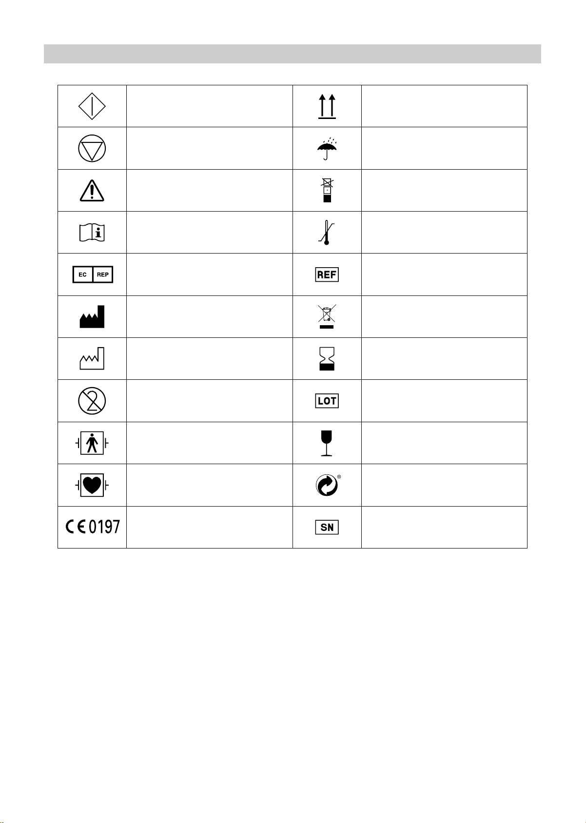
1-3. Meaning of Symbols
Start (of action) This way up
Stop (of action) Keep away from rain
Caution
(Refer to safety information)
Stacking limit by number
Consult instructions for use Temperature limitation
Authorised representative in the
European community
Catalogue number
Manufacturer Disposal instructions
Date of manufacture Use by
Do not reuse Batch code
Defibrillation-proof type BF
applied part
Fragile; Handle with care
Defibrillation-proof type CF
applied part
Gruene Punkt
(Green point in German)
CE mark Serial number
Page 8
6
1-4. Safety Information
The warning signs and symbol examples indicated below are intended to ensure safe use of the
product and prevent damage and injury to you and others. The signs and symbols are explained
below.
Explanation of Symbols
* Physical damage means serious damage to your house and household goods, and serious injury
to pets or other domestic animals.
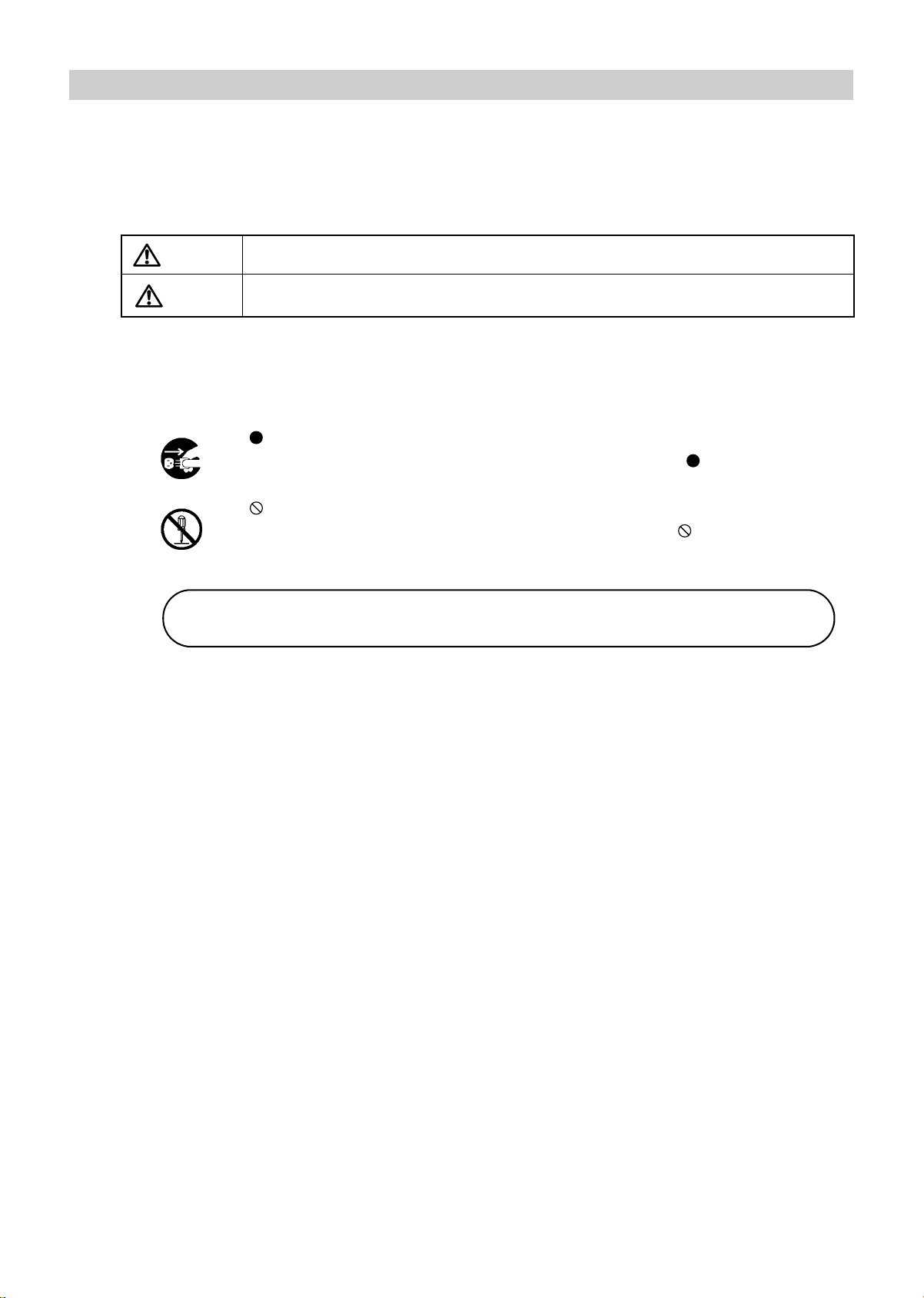
Warning
Indicates a situation where incorrect handling may cause human death or serious injury.
Caution
Indicates a situation where incorrect handling may cause human injury or physical
damage.*
indicates "mandatory" (an action that must be observed).
The actual action that is mandatory is indicated inside or next to .
The icon at left indicates "disconnect the power plug".
indicates "forbidden" (an action that must not be taken).
The actual action that is forbidden is indicated inside or next to
.
The icon at left indicates that "disassembly is forbidden".
Note:
This indicates information that should be known when operating the device.
Page 9
7
1-4. Safety Information
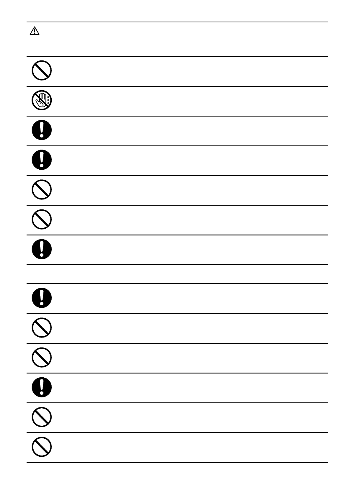
Warning:
Safety rules when using the product
Do not use a frayed or damaged power cord or plug. Otherwise electric shock, short circuiting, or fire
may result.
Do not touch the power plug with wet hands. Otherwise electric shock or injury may result.
Be sure to plug the three-prong power plug into a grounded (three-prong) outlet for medical use
(when a printer is included). Otherwise electric shock or current leakage may result.
Use a dedicated outlet. Otherwise electric shock or current leakage may result.
Do not poke or scratch the buttons or display with a sharp or pointed object. Incorrect diagnosis and
treatment or an accident may result.
Do not connect the power plug to the outlet if the electrical ratings are outside the specified range below:
100 - 240 VAC. This may cause fire.
Do not touch the unit when discharging a defibrillator.
Safety rules when performing measurement
This device is only to be used by qualified medical personnel, or under the guidance of such
personnel. Otherwise incorrect diagnosis and treatment or device failure may result.
The results of measurement should only be interpreted by a doctor. If you are concerned about a
measurement result, consult your doctor. Otherwise incorrect diagnosis and treatment may result.
This device is intended to perform measurement for examination. Do not use the device for patient
monitoring. Otherwise an accident may result.
If pressurization does not stop during measurement or another abnormal condition occurs, remove
the cuff or air tube and disconnect the power. Otherwise peripheral nerve may be damaged.
Use only the specified supplies for the cord, cuff, USB devices, and other parts. Do not install other
than specified options. Otherwise an accident may result.
Do not connect the air tube or cuff to any other device tubes attached to the body. Otherwise air may
enter the blood vessels and an accident may result.
Page 10
8
1-4. Safety Information
Do not attach the arm cuff for patient during medical treatment with intravenous drip or blood
transfusion. This may result incorrect diagnosis and treatment.
Do not use this device on a patient that cannot express pain. If cuff pressurization does not stop in a
specified time, internal hemorrhaging may occur in the upper arm or ankle.
This device cannot be used during MRI imaging. This may cause an accident.
Pay constant attention to patient's condition during measurement. Otherwise an accident may result.
Do not perform measurement without cleaning and sterilizing the device, cuffs and sensors after
measuring for patient with infection.
Pay extra attention to a patient with pacemaker during measurement. Rate meters may continue to
count the pacemaker rate during occurrence of cardiac arrest or some arrhythmias. Do not rely
entirely upon rate meter alarm. Refer to the pacemaker pulse rejection capability in this manual.
Installation
As this device conforms to the IEC60601-1-2 standard, it can be used in combination with another
medical device. While or after an electrosurgical knife or a device which generates noise being used
near this device however, make sure that it is properly functioning. Otherwise incorrect diagnosis
and treatment or device failure may result.
Do not use this device in the presence of a flammable gas such as a highly inflammable anesthetic,
or in a high-pressure oxygen chamber or tent. Fire and explosion may result.
Do not install or store the device in a location where water or chemicals may splash on the device.
Electric shock may result.
Do not connect any electric device, without the approval of IEC60601-1, or not fulfilling IEC60601-1-1.
For the use of a PC or a printer with this device, the connecting device should be approved
according to standards mentioned above. (This unit meets the restricted level of leakage current
required for medical devices and it does not include all the connected devices. Connecting to other
device is not allowed unless the total leakage current of such a combination is within the restricted
level.) Neglecting this caution, it could cause electric shock to the device.
Maintenance
After cleaning the device, dry it completely before turning on the power again.
Otherwise electric shock or current leakage may result.
Page 11
9
1-4. Safety Information
Caution:
Safety rules when using the product
Observe the rules below when handling the power cord. Failure to observe these rules may result in
electric shock or device failure.
•Do not damage the cord
•Do not break the cord
•Do not modify the cord
•Do not bend or pull on the cord with undue force
•Do not twist the cord
•Do not tightly coil the cord when in use
•Do not place heavy objects on the cord
•Do not let the cord become pinched
Insert the power plug all the way into the outlet. Otherwise electric shock, short circuiting, or fire may
result.
Wipe dust off the power plug. Otherwise electric shock, short circuiting, or fire may result.
After using the device, turn the power switch to the "off" position and disconnect the power plug.
Failure to do so may cause deterioration of the insulation and result in electric shock, current
leakage, or fire.
When removing the power plug from the outlet, grasp and pull on the plug, not the cord. Pulling on
the cord may break wires and cause a short circuit, resulting in fire or electric shock.
If a power failure occurs while using the device, turn the power switch to the "off" position and
disconnect the power plug. Failure to do so may result in a product failure or other problem.
If the device becomes wet, wipe it completely dry with a soft cloth before use. Otherwise electric
shock, short circuiting, or fire may result.
Safety rules when performing measurement
If the patient has any of conditions below, do not perform measurement. Otherwise incorrect
diagnosis and treatment may result.
•The patient has an aneurysm
•The patient has insufficient peripheral circulation, noticeably low blood pressure, or low body
temperature.
•The patient frequently has an irregular pulse.
In the following situations, check by auscultation or palpation. Otherwise incorrect diagnosis and
treatment may result.
•When irregular pulse waves are indicated.
External vibration or patient movement during measurement may cause an incorrect indication.
•When an error occurs or when a measured value is questionable.
Page 12
10
1-4. Safety Information
If a power failure occurs during measurement, immediately remove the cuff. If the patient's ankle or
upper arm is pressurized for a long time, internal hemorrhaging may result.
Do not attach the cuff on the measurement site below:
•Arm with intravenous drip
•Upper limb in which a shunt is placed in for hemodialysis
Incorrect diagnosis and treatment or an accident may result.
If there is acute inflammation, a pyogenic ailment, or an external wound where the cuff is to be
attached, follow the instructions of a doctor. Symptoms may become worse.
When there is impossibility of test or doubts about the measurement values, please confirm the
patient's condition first. The patient's condition may have deteriorated to the point where
measurement limits are exceeded. Always verify that the cuff and cuff hose are appropriately used
and are not bent or blocked.
If the display continues to show 0, the monitor's pressure may be 0. But if the cuff hose is blocked or
bent there may be air remaining in the cuff. At this time disconnect the hose from the cuff to ensure
that blood flow is not restricted and no disorders occur to the peripheral nerves.
When using the device in combination with another medical device, read the manual of the other
device well and understand all warnings and cautions. Incorrect diagnosis and treatment may result.
Do not use the device in a location with loud noise. Incorrect diagnosis and treatment may result.
Attach the PCG sensor correctly. Incorrect diagnosis and treatment may result.
Take care that the PCG sensor does not fall on the patient. This may cause injury.
Wrap the cuff on bare skin or on a thin layer of clothing. Otherwise internal hemorrhaging may result.
Make sure that the ECG clips are attached in the correct positions. Otherwise incorrect diagnosis
and treatment may result.
Do not use the device near a cellular phone. Incorrect diagnosis and treatment may result.
Do not use in an MRI, CT, X-ray room, an operating room, or other rooms where radio noise is
generated. Incorrect diagnosis and treatment or an accident may result.
Do not use a worn or expired ECG clip electrode or PCG sensor pad. Otherwise incorrect diagnosis
and treatment may result.
(ECG clip electrode and PCG sensor pad have an expiry date. After the expiry date, the pad
becomes dry and incapable of accurate measurement. Use only a pad or electrode whose indicated
expiry date has not passed. Refer to page 12 for how to confirm the expiry date.)
Page 13
11
1-4. Safety Information
On a bedridden patient, check for lower-limb deep venous thrombus before taking a measurement.
Otherwise an accident may result.
The ECG clip electrode and PCG sensor pad are disposable supplies. Do not reuse them once they
are removed. In case that they are used on moist, injured or infected skin, dispose them right away.
Otherwise an infection may result.
The sensor box removal lever uses a strong spring mechanism. Take care not to injure yourself on
the metal edges. Hold the sensor box firmly and press down hard on the lever from the exterior to
remove the connector. This may cause injury with the metal edges.
Do not use an air hose of an arm cuff or an ankle cuff that is bent or collapsed. Incorrect diagnosis
and treatment may result.
Installation
Do not install in a location where the temperature or humidity is outside the allowed range. This may
cause malfunctioning or device failure.
Do not use in a moving vehicle such as an ambulance. Incorrect measurement may result.
Incorrect diagnosis and treatment or an accident may result.
If you are not using the device stand, exercise sufficient caution when moving the device. The device
is heavy and may slip out of your hands, causing injury.
Do not place objects on the device. This may cause injury.
Maintenance
Do not disassemble, repair or modify the device. This may cause electric shock.
Before cleaning or maintaining the device, disconnect the power plug. Otherwise electric shock or
injury may result.
Page 14

12
1-4. Safety Information
Important:
Before use
• Make sure that all cords and tubes are firmly connected.
• Inspect dials and buttons and verify that the device operates correctly.
• Check printer toner, paper, and other supplies.
• Confirm the expiry date of the ECG clip electrode or the PCG sensor pad.
The expiry date can be calculated from the lot number as follows:
During use
• Do not pressurize when the cuff is not wrapped.
• Do not use a torn cuff.
• The device may be used on the patients below. If used on patients other than those described
below, incorrect measurement may result or measurement may not be possible.
- Height: 120 to 210 cm
- Girth of arm: 20 to 32 cm (using the standard cuff) / 16 to 38 cm (using the optional cuff)
- Girth of ankle: 16 to 33 cm
• Do not disconnect the USB or LAN cable while data is being transmitted. This may corrupt the
data.
• Do not turn off the power during printing, data transmission, or writing.
• Do not pull out the paper before printing is finished.
• Make sure the date and time setting is correct. If the date and time setting is not correct, the date
and time of measurement will not be recorded correctly.
• Do not connect an ECG clip to another conductive part including the ground.
• The electrical energy from a defibrillator may damage the device. During defibrillation, remove the
sensors from the patient and do not touch the device.
• When moving or using the device, do not drop or subject the device to shock. This may cause the
electric components and precision mechanisms to fail.
After use
• Clean the device and accessories and arrange properly for storage.
• Do not wash or moisten the cuff
• Do not use solvents such as thinner, benzene, or concentrated alcohol to clean the device
• Do not use an autoclave, ultraviolet radiation, or gas disinfection (EOG, formaldehyde gas,
concentrated ozone, etc.) to disinfect the device
• If a fuse blows, there may be a problem in the device. Contact a dealer or an Omron Healthcare
technical support representative
• Do not install the unit in the following locations
- A location with prolonged exposure to direct sunlight
- A location with dusty or salt air
- On an inclined surface or a location subject to vibration, shock, or noise
- A location where chemicals are stored or gas is emitted
• If the patient has one of the following conditions, a correct measurement may not be obtained
- The patient has body movements due to convulsions caused by rheumatism or otherwise
- The patient has diabetic arteriosclerosis (blood pressure at leg joints tends to be high)
- The patient has false high blood pressure
- The patient has convulsions or tremors
• When the unit is incapable of ECG measurement, the message "Electrode removed" is displayed.
Lot Number:
Production Date: 2006 July 10th
Expiry Date: 2008 July
6071011
(2 years after the production date)
(Example)
Page 15
13
1-5. Product and Accessories
Before using this product, make sure that no accessories are missing and that neither the unit nor
the accessories are damaged. Contact a dealer or an Omron Healthcare technical support
representative If any accessory is missing or damaged.
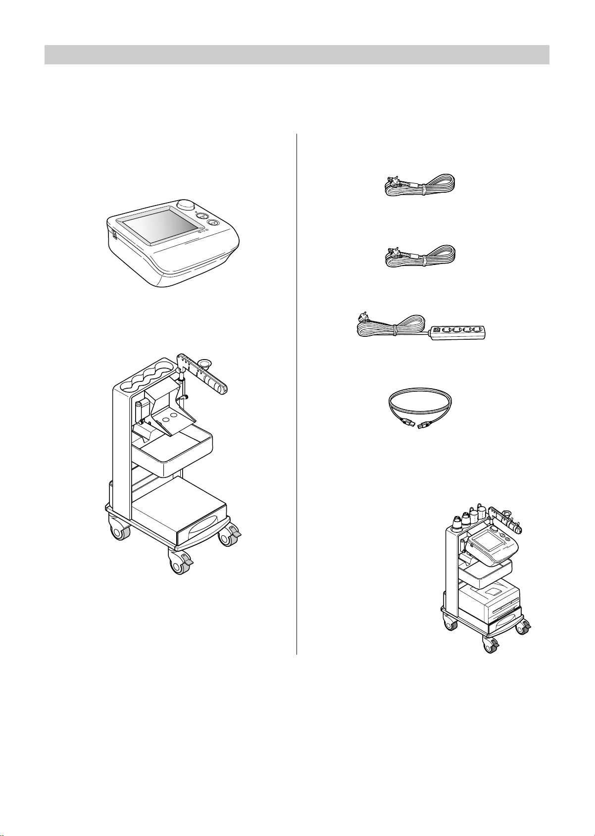
Main Unit
Non-invasive Vascular Screening Device
BP-203RPE3
Standard Accessories
BP-203RPE3 stand
BP-203RPE3 stand cover
BP-203RPE3 hook-and-loop fastener
for the sensor box
Power cord for main unit (0.8 m)
Power cord for printer (1.1 m)
BP-203RPE3 power tap
USB cable (for printer)
Items on this page will be assembled on
delivery as follows:
Page 16
14
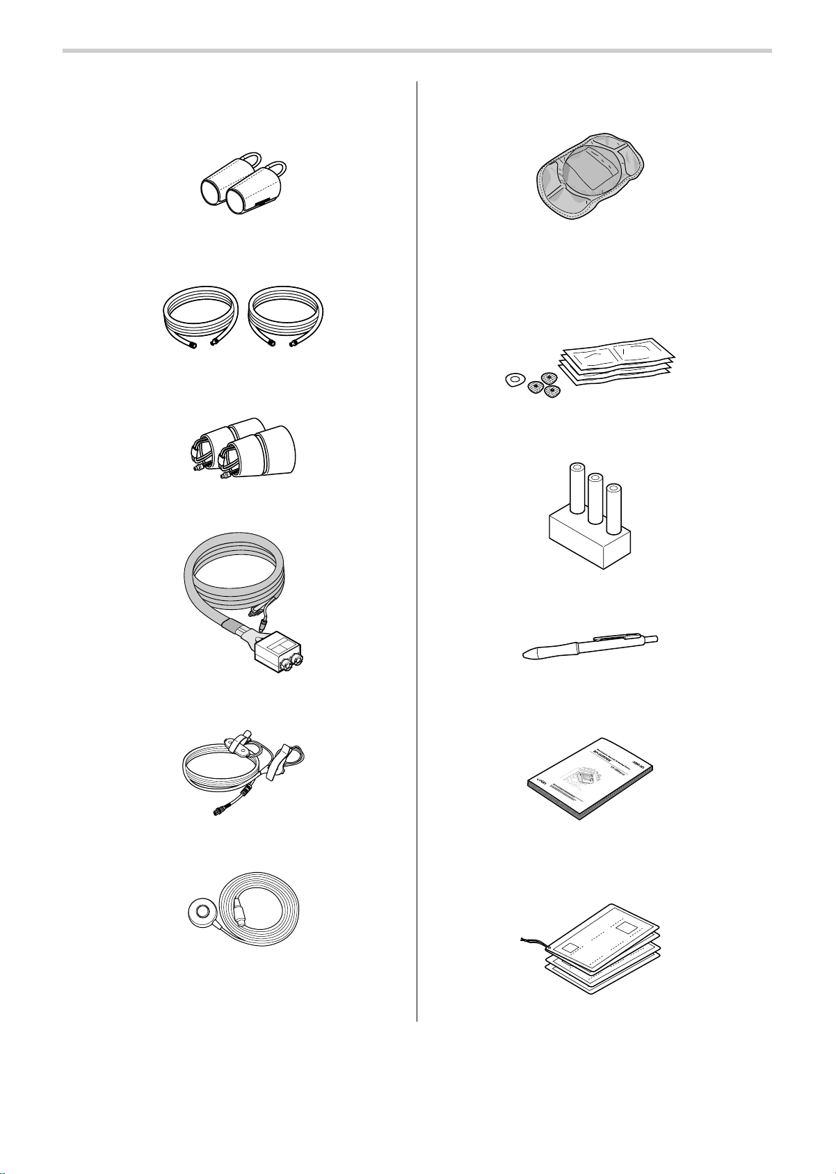
1-5. Product and Accessories
BP-203RPE3 arm cuffs, left and right pair
(M size: For arm girths from 20 to 32 cm)
BP-203RPE3 arm cuff hoses, left and right
pair
BP-203RPE3 ankle cuffs, left and right
pair
Sensor box
ECG clips
Phonocardiogram sensor (PCG sensor)
PCG weight
Sensor gel packet (consumable packet) 5
sets
• PCG sensor pad, 1 piece x 5
• ECG clip electrodes, 3 pieces x 5
Blood vessel model
BP-203RPE3 touch pen
BP-203RPE3 manual
Quick manuals
Page 17

15
1-5. Product and Accessories
Accessories (Sold Separately)
Product description REF Model
Right arm cuff, S size 9999492-9 HEM-CS30-RIGHT
Right arm cuff, M size 9999490-2 HEM-CR30-RIGHT
Right arm cuff, L size 9999496-1 HEM-CL30-RIGHT
Left arm cuff, S size 9999494-5 HEM-CS30-LEFT
Left arm cuff, M size 9999491-0 HEM-CR30-LEFT
Left arm cuff, L size 9999498-8 HEM-CL30-LEFT
Arm cuff air tube (right) 9999505-4 HEM-CR30R-TUBE
Arm cuff air tube (left) 9999504-6 HEM-CR30L-TUBE
Ankle cuff (right) 9999500-3 HEM-CR31-RIGHT
Ankle cuff (left) 9999501-1 HEM-CR31-LEFT
ECG clips 9999503-8 HFA-RPE3-ECG
PCG sensor 9999507-0 HFA-RPE3-PCG
PCG weight 9999506-2 HFA-RPE3-W700
Sensor gel packet (20 sets) 9967933-0 HBP-FORM-101S
Blood vessel model 9999510-0 HFA-FORM-ARTVS
Touch pen 9996749-2 HBP-PEN
LAN cable (for hub use) 9997621-1 HFA-RPE3-LANS
LAN cable 9997622-0 HFA-RPE3-LANX
Toe standard disposable cuff 9957110-6 HBP-DCUFF-TBI31
Toe small disposable cuff 9957111-4 HBP-DCUFF-TBI32
Toe cuff tube (right) 9957112-2 HBP-FORM-TBICR
Toe cuff tube (left) 9957113-0 HBP-FORM-TBICL
Table-tap 9515310-5 HBP-RPE3-TAKO
Stand cover 9511950-0 HFA-RPE3-CVR
Hook-and-loop fastener for the sensor box 9511951-9 HFA-RPE3-SBF
Page 18
16
1-5. Product and Accessories
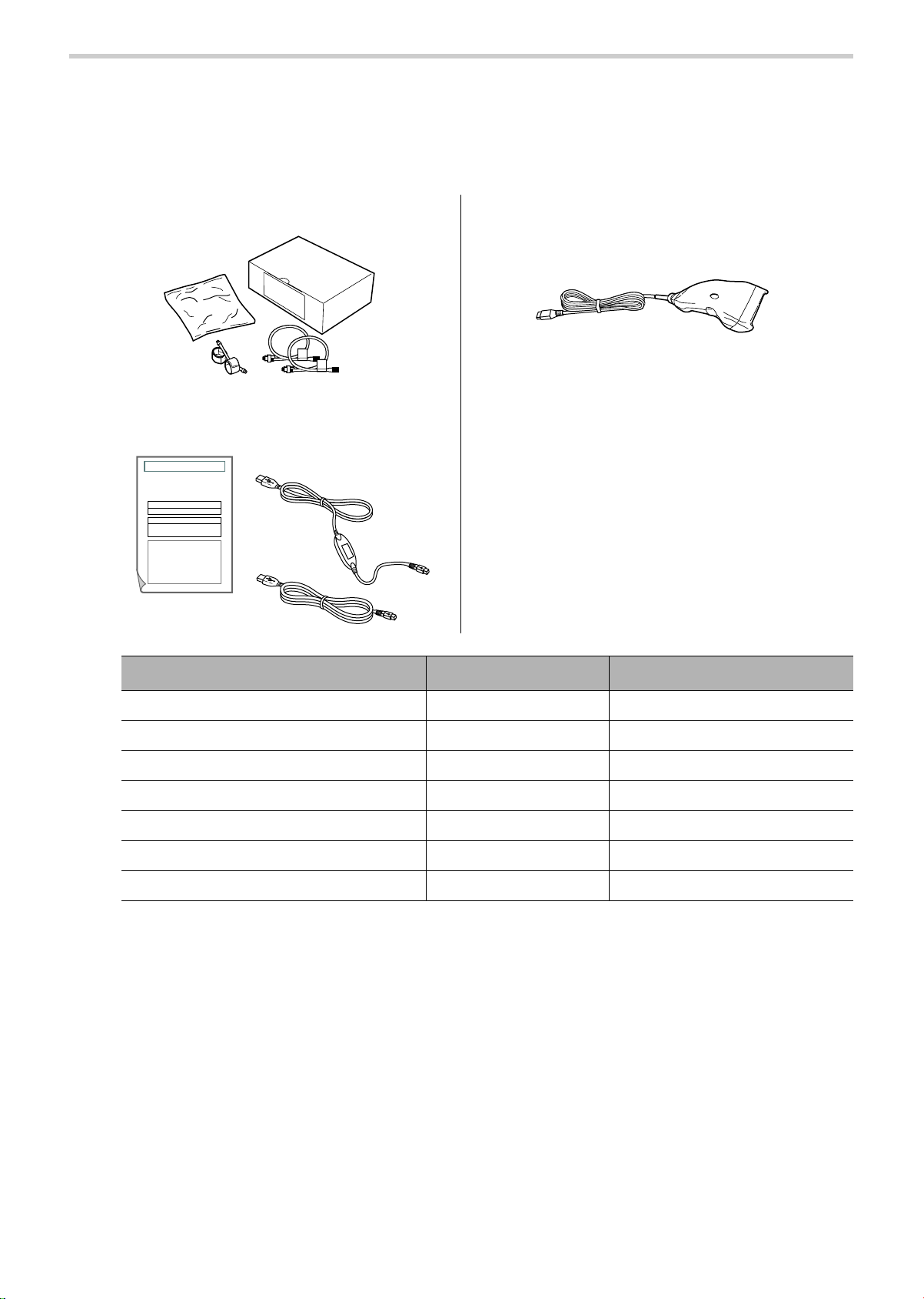
Options
Software and unit options can be purchased to expand the functionality of the product. For
details on the uses and functions of the options, see Chapter 4.Refer to "4-1. Options"
(page 121)
TBI package
HMC package
BP-203RPE3 bar code reader set
• Bar code reader
• Attachment fittings
Product description REF Model
TBI package 9512233-1 HFA-TBI-ENG
HMC package 9512232-3 HFA-RPE3-HMCPE
USB cable for HMC package 9903144-6 HBP-RPE3-USB
Serial cable for HMC package 9903143-8 HBP-RPE3-SER
Bar Code Reader Set 9996743-3 HBP-RPE3-BAR
TBI package manual 9512236-6 HFA-RPE3-TBIME
HMC package manual 9512235-8 HFA-RPE3-HMCME
Affix S/N label
BP-203RPE3 Unit Serial Number
Product Package Classification
HMC Package
OMRON HEALTHCARE CO., LTD.
Non-invasive Vascular Screening Device BP-203RPE 3
Product Package License Certificate
This certificate is a registration certificate for the product package that
you purchased, and certifies that you, the customer, have lawfully
received a license from OMRON HEALTHCARE Co., Ltd.
OMRON HEALTHCARE Co., Ltd. permits the customer to install and
use this product package on the BP-203RPE 3 unit indicated in this
license certificate.
Page 19
17
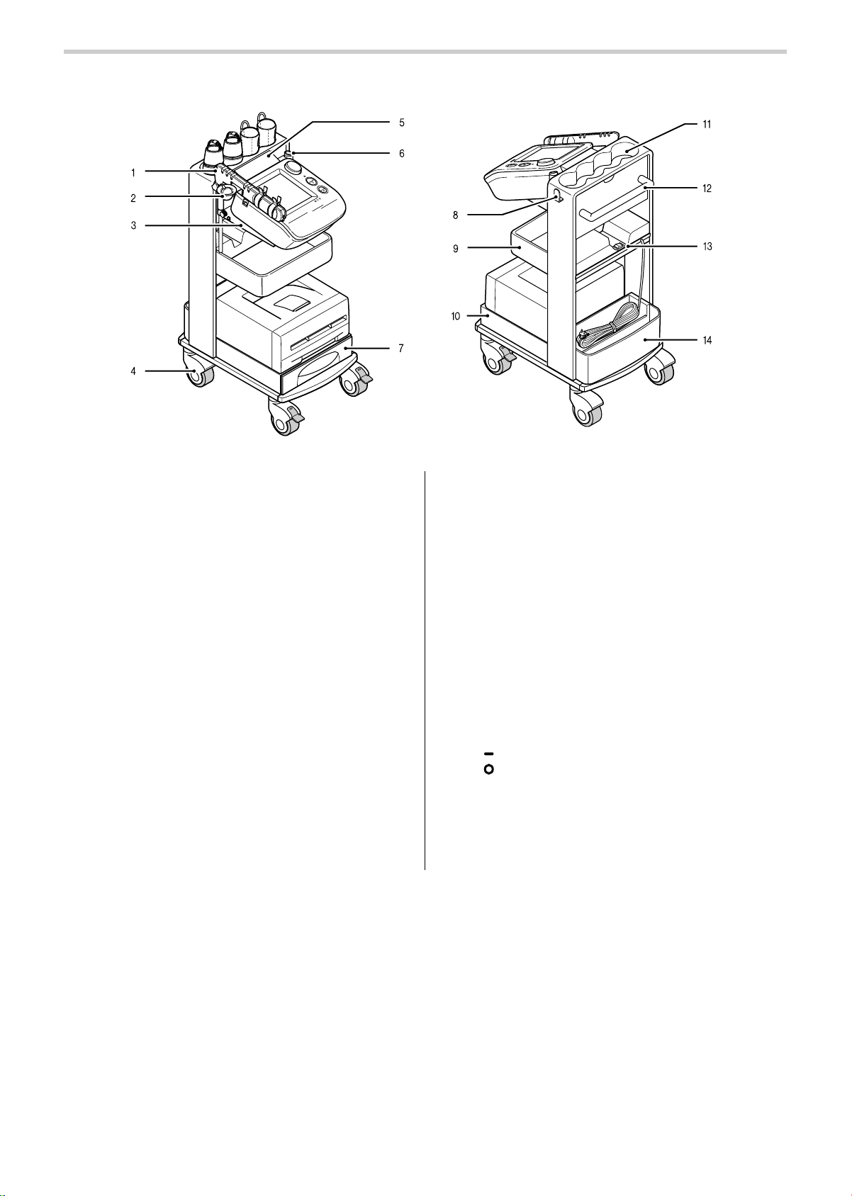
1-6. Name and Function of Each Part
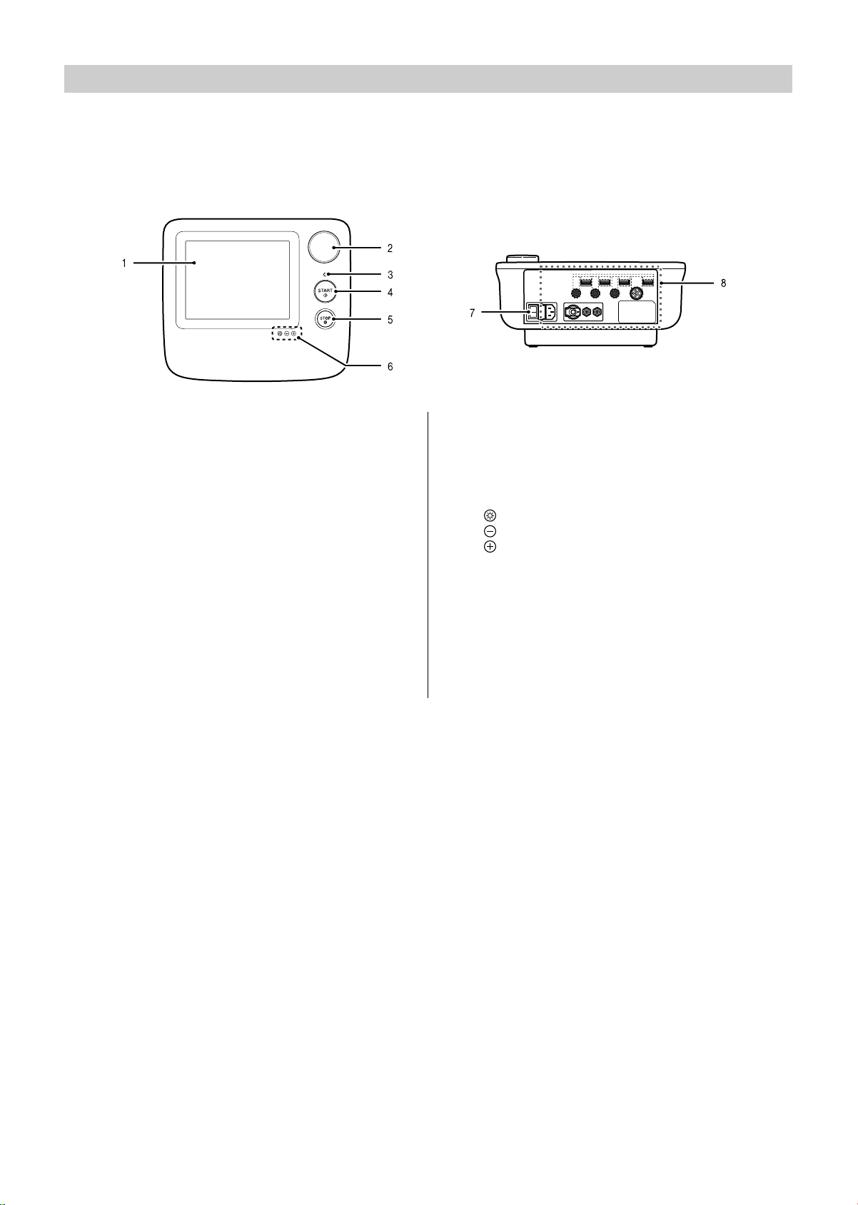
Main Unit
Enter patient information, configure settings, and perform measurement.
Top Back
1. LCD display (touch panel)
When configuring settings: Setting buttons appear.
Touch the setting buttons with the touch pen to enter
settings.
During measurement: Measured values, measured
waveforms, and operation buttons appear.
2. Jog dial
Settings can be entered using the jog dial.
Turn the jog dial right or left to select an item and
press to enter.
3. Display lamps
Off: Power is off
Green (on): Power is on (normal mode)
Orange (on): Power is on (sleep mode)
4. [START] button
Press to begin measurement.
5. [STOP] button
Press to interrupt and stop measurement.
On the screen with the [BACK] button, the [STOP]
button can be also used to return to the previous
screen.
6. Brightness button
: This enables the "-" and "+" brightness buttons.
: This darkens the screen.
: This makes the screen brighter.
7. Power on/off switch
Turns the power on and off. The power is normally
turned on and off with the power switch on the stand,
so keep the main unit power switched on.
8. Connectors
For details on the connectors, see Chapter 5.
Refer to "5-3. Connections" (page 127)
Page 20
18
1-6. Name and Function of Each Part
Stand
1. Arm
The sensors are placed on this arm.
2. PCG sensor pocket
Stores the PCG sensor.
3. Main unit holder
The main unit is placed on this holder.
4. Casters
During examination, lock the casters to keep the
stand from moving. Unlock before moving the stand.
5. Cable cover
This prevents dust from collecting on the connectors
on the back of the main unit.
6. Arm stand / touch pen stand
Attach the arm either on the left or the right. Insert
the touch pen stand on the side that is empty.
Refer to "5-4. Changing the Arm Position"
(page 129).
7. Drawer
Store printing paper and other supplies in the drawer.
8. Cable hook
Hang the sensor box cable on this hook.
9. Tray
Stores supplies on the tray.
10.Laser printer holder
11.Cuff storage pocket
Store arm and ankle cuffs.
12.Handle
Hold this when moving the main unit.
13.Power on/off switch
Turns the power of the main unit, printer, and options
on/off at the same time.
( ) position is to turn on the power.
( ) position is to turn off the power.
14.Back pocket
Stores manuals and the power cord (when moving
the stand).
Page 21

19
1-7. Installation/Moving
Inspection Before Starting Work
For safe and proper use, inspect the device at the start of each day. When installing the device, be
sure to follow the instructions on pages 7 to 12.
Before turning the power on
Main Unit
• Is the sensor that directly touches the patient clean?
• Are the cords arranged properly?
• Is the device kept dry?
• Is there no damage on the device?
• Are the casters not broken or caught by any foreign object?
Power Cord
• Is the power cord placed safe from people stepping on?
• Are the power cords not damaged? Is power-line not exposed? Is the power cords not frayed?
Supplies
• Are ECG clip electrodes and PCG sensor pads ready?
• Does the printer have enough toner and paper?
• Is paper loaded in the printer?
After turning the power on
Main Unit
• No smoke or abnormal smell?
• No abnormal noises?
Check the date and time setting
• Are the date and time correct?
If not, see page 93 to set the correct date and time.
Warning
Do not install or store the device in a location where water or chemicals may splash on
the device. Electric shock may result.
Caution
Do not install in a location where the temperature or humidity is outside the allowed
range. This may cause malfunctioning or device failure.
Page 22

20
1-7. Installation/Moving
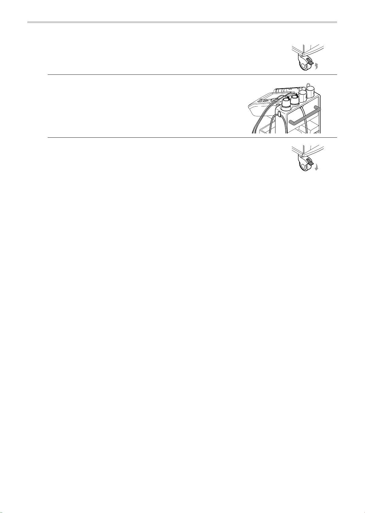
Procedure for Moving
When you need to move the device, follow the procedure below.
1. Turn the power switch to the off ( ) position.
2. Remove the power plug from the outlet and coil the
cord.
Please do not pull the power cord.
3. Store the sensors on the arm.
4. Store the cuffs in the cuff storage pocket.
5. Hang the sensor box cable on the cable hook.
Page 23
21
1-7. Installation/Moving
6. Unlock the casters.
7. Grasp the handle and move the device.
Do not push or pull any other parts rather than the
handle.
8. After moving the device, lock the casters to secure
the stand.
Page 24
22
2. Measurement Procedure
2-1. Preparing for Measurement
Measurement Procedure
Turn the power on
Enter or check patient information
Attach the cuffs and sensors to the patient
Make sure that "ECG: OK" and
"PCG: OK" appear on the display
Press the [START] button
Measurement starts
To stop measurement,
press the [STOP] button
Measurement ends.
Measurement results will be displayed and/or
measurement report will be printed.
Have the patient in a supine position on
the bed and remain quite
Page 25

23
2-1. Preparing for Measurement
Patient Information
Patient information is required to properly maintain a measurement history. Input items marked
"Required" must be entered.
*Entry is only required if it will be used with the initial screen set to order
number entry. Patient information must be stored in advance.
There are two methods for entering patient information.
A Enter the patient's information on the touch panel at the time of measurement.
B Enter the patient's information in advance from "Advanced Registration of Patient Information".
This is convenient for group examinations.
Refer to "3-8. Advanced Registration of Patient Information" (page 105).
Item name Input Page
ID
Required
26
Sex
29
Birth Date
30
Height
31
Name
Optional
28
Weight
31
Waist
32
Disease
32
Order Number*
33
Measurement
Sensors
34
Measurement
Sites
35
Upper limit of
pressurizing
36
Synchro
measurement
38
Doctor
38
Technician
39
Category
39
Page 26
24
2-1. Preparing for Measurement
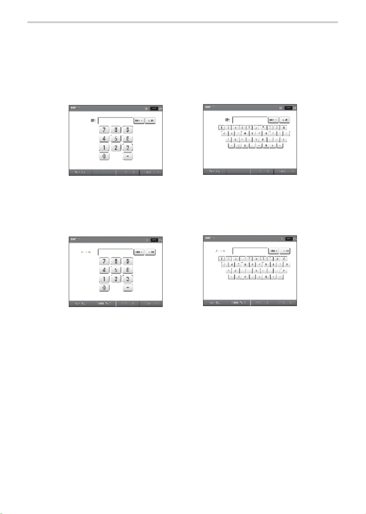
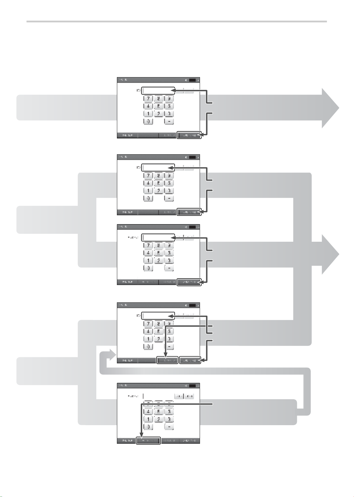
Initial Screen (ID Entry Screen)
Following a brief interval after the power is turned on, the ID entry screen appears. This screen is
called the "initial screen" in this manual. The ID is entered in this screen.
You can select whether the ID input type is all numbers, or both numbers and alphabetical
characters. It is recommended that you decide which type of ID will be used in advance.
The first time the power is turned on, the left-hand screen below appears. This screen is for
number entry. If you wish to use combined number and character IDs, change the "ID Input type" in
advance.
Refer to "3-2. User Default Settings" "ID Input Type" (page 76).
If you manage data by "Order Number" associated with the electronic chart, you can change the
initial screen from the ID entry screen to the order number entry screen. To use order numbers,
patient information must be stored in advance.
Refer to "3-2. User Default Settings" "Search Key" (page 76).
[MAIN MENU] button: Touch this to change to the main menu screen. The main menu screen is
used to configure basic settings (refer to page 74).
[SWITCH TO ID] button:If you are measuring a patient that does not have an order number, you
can change back to ID number entry.
Initial screen (ID input type: numbers)
Initial screen (ID input type: numbers and characters)
Initial screen: order number entry screen
(Input type: numbers)
Initial screen: order number entry screen
(Input type: numbers and characters)
Page 27

25
2-1. Preparing for Measurement
Entering and Editing Patient Information
Enter the patient information and edit previously stored patient information.
Notes:
• Do not assign multiple IDs to a single patient. Even if all other information such as the
name is the same, the system will treat different IDs as different patients. In this case, you
will not be able to make full use of the device's functions for long-term storage of
measurement histories and diagnosis support.
• The number of digits must be the same or the ID will treated as two separate IDs.
Example: "300" and "0300".
The above will be treated as two separate IDs.
• The [ID], [SEX], [BIRTH DATE], and [HEIGHT] must be entered.
If not entered, measurement cannot be performed.
• Once ID number or order number is entered in the initial screen, the "ID" or "Order
Number" cannot be changed.
• Take care to avoid mistakes when entering information and numerical values,
as the examination results will be printed based on this information.
• If you return to the initial screen without saving patient information,
the information will be cleared.
Page 28
26
2-1. Preparing for Measurement
Entering the ID Number
Follow the steps below to enter an ID number for the first time or check existing ID numbers. Up to
13 characters (including hyphens "-") can be entered. ID number must be entered.
For entering an Order number, up to 16 digits of number (including hyphens"-") can be entered.
*The initial screen for "ID input type: numbers" is shown as an example. The key arrangement is different for "ID input
type: numbers and characters".
First-time patient
Patient information
not registered
1 Enter a new ID number
1 Enter the ID number
2 Press the [SEARCH / NEXT] button
1 Enter the order number
2 Press the [SEARCH / NEXT] button
2 Press the [SEARCH / NEXT] button
3 Press the [SEARCH / NEXT] button
Patient for whom
patient information is
already registered
Patient information
already registered
Patient for whom
re-measurement is
necessary due to
inadequate
measurement results
Previously measured
(patient information
already registered)
1 Press the [PREVIOUS ID] button
1 Press the [SWITCH TO ID]
button
2 Check the ID number
* Press the [SWITCH TO ID] button
to change to the ID entry screen
Page 29
27
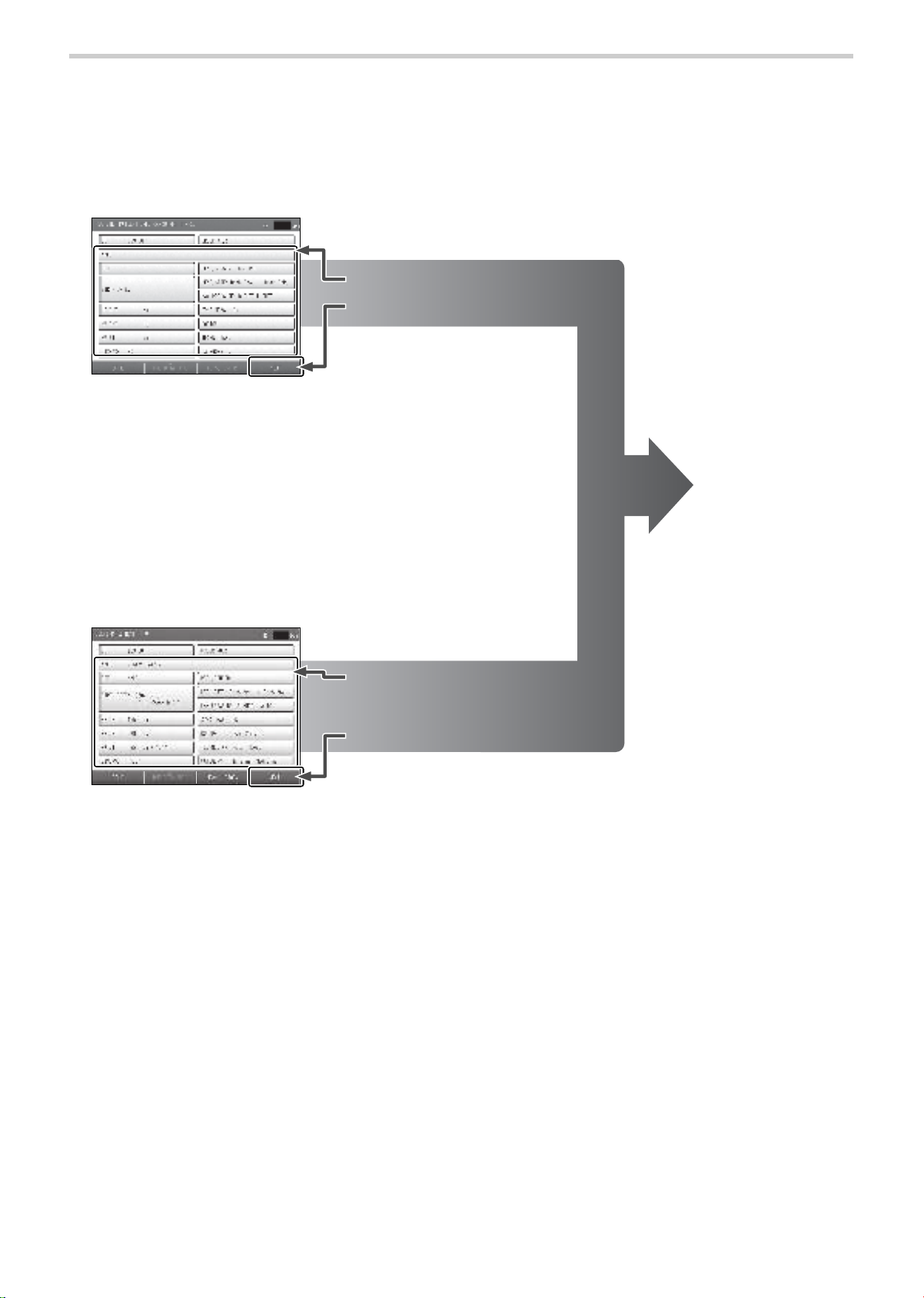
2-1. Preparing for Measurement
Register patient information screen
For the items to be entered,
see pages 28 to 39.
For the items to be entered,
see pages 28 to 39.
[BACK] button: Return to the initial screen.
[HMC DATA PROC] button:
Can be used when the optional HMC Package is connected.
[NEXT] button: Proceed to the measurement screen.
[MEAS. HISTORY] button: Show the patient's measurement history.
[BACK] button: Return to the initial screen.
[HMC DATA PROC] button:
Can be used when the optional HMC Package is connected.
[NEXT] button: Proceed to the measurement screen.
1 Enter patient information
2 Press the [NEXT] button
2 Press the [NEXT] button
1 Check the patient information.
Enter any items that have not
been entered as needed.
The measurement
screen will appear.
Attach the cuffs and
sensors to the patient
and start measuring.
Refer to page 41.
Confirm patient information screen
Page 30
28
2-1. Preparing for Measurement
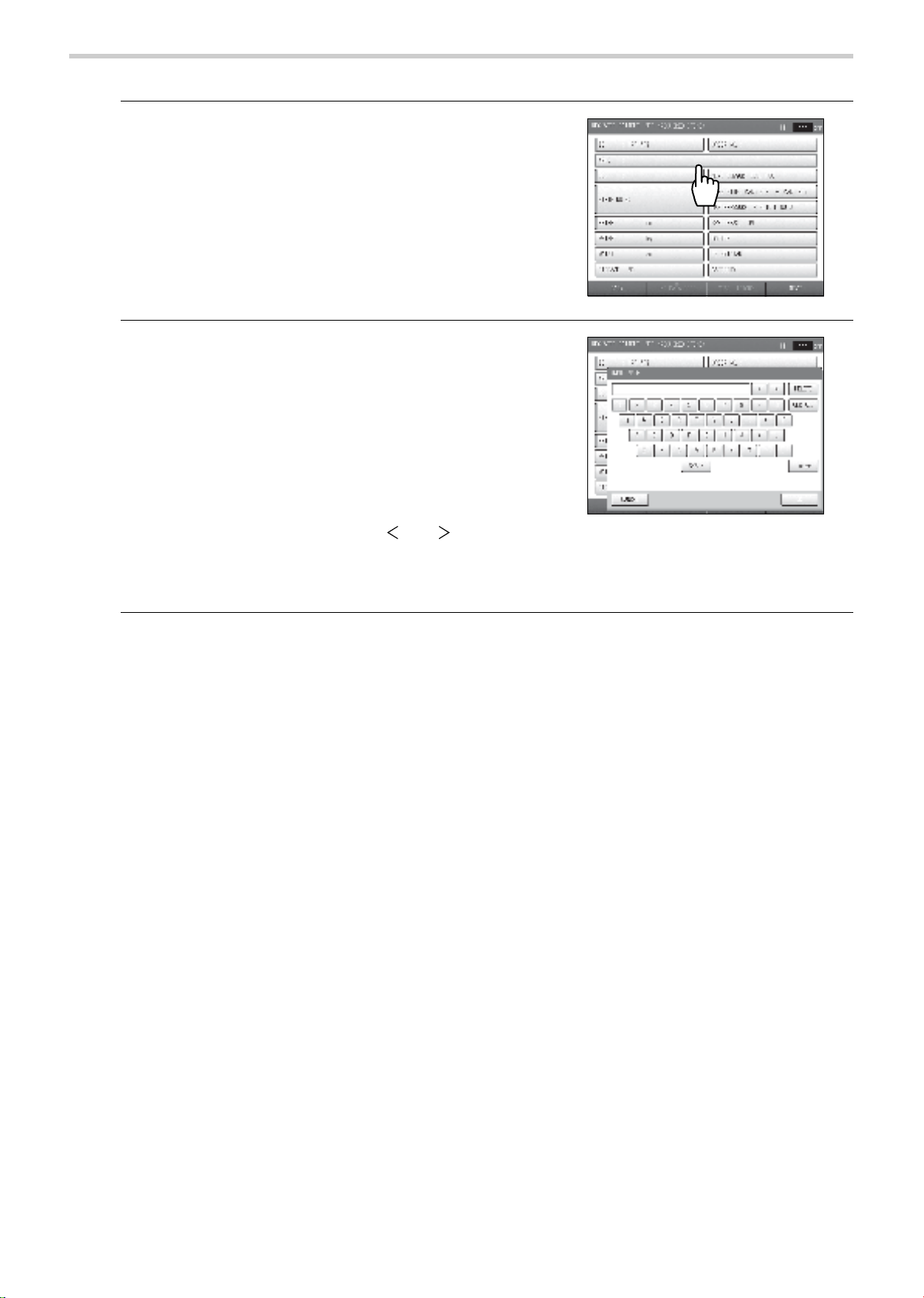
Entering the Name
1. Press the [NAME] button.
2. Enter the name.
• Up to 40 characters can be entered.
• A space counts as one character.
• To enter a space, press the [SPACE] button.
• To switch between upper case and lower case letters,
use the [UPPER] button / [lower] button.
When upper case entry is selected, the [lower] button
appears. When lower case entry is selected, the
[UPPER] button appears. Each time the button is
pressed, it changes between [UPPER] and [lower].
• To change a character, press the [ ] or [ ] button to
move the cursor to that character, press the [DELETE]
button, and enter the new character.
• To delete all characters that have been entered, press the [CLR ALL] button.
3. Press the [OK] button.
To cancel entry, press the [CANCEL] button.
Page 31

29
2-1. Preparing for Measurement
Entering the Sex
This must be entered. If not entered, measurement cannot be performed.
1. Press the [SEX] button.
2. Press the [SEX] button to select the sex.
The selection switches between "Male" and "Female"
each time you press the [SEX] button.
Page 32

30
2-1. Preparing for Measurement
Entering the Date of Birth
This must be entered. If not entered, measurement cannot be performed.
A date of birth less than one year prior to the day the information is being entered cannot be
entered. The device cannot be used for an infant less than one year old.
1. Press the [BIRTH DATE] button.
2. Enter the day, month, and year of birth.
Enter the date in the format "yyyy/mm/dd".
3. Press the [OK] button.
To cancel entry, press the [CANCEL] button.
Page 33

31
2-1. Preparing for Measurement
Entering the Height
This must be entered. If not entered, measurement cannot be performed.
The height is required for calculation of the PWV (Pulse Wave Velocity).
1. Press the [HEIGHT] button.
2. Enter the height and press the [OK] button.
• The input range is 120 cm to 210 cm.
• To cancel entry, press the [CANCEL] button.
Entering the Weight
The weight is required for calculation of the BMI (Body Mass Index).
1. Press the [WEIGHT] button.
2. Enter the weight and press the [OK] button.
• The input range is 25.0 kg to 300.0 kg.
• To cancel entry, press the [CANCEL] button.
Page 34

32
2-1. Preparing for Measurement
Entering the Waist
1. Press the [WAIST] button.
2. Enter the waist and press the [OK] button.
• The input range is 30 cm to 250 cm.
• To cancel entry, press the [CANCEL] button.
Selecting the Disease
1. Press the [DISEASE] button.
2. Select the disease and press the [OK] button.
• Press the button of the applicable disease so that a
checkmark appears.
• Multiple items can be selected.
• If none is applied, select [NO].
• To cancel entry, press the [CANCEL] button.
Page 35

33
2-1. Preparing for Measurement
Entering the Order Number
The order number used for the electronic chart can be entered.
1. Press the [ORDER NO.] button.
2. Enter the order number.
Up to 16 digits, including hyphens (-), can be entered.
3. Press the [OK] button.
To cancel entry, press the [CANCEL] button.
Note:
Once a patient information screen has been opened by entering the ID number or order number
in the initial screen, entering and changing is not possible.
Page 36

34
2-1. Preparing for Measurement
Setting the Measurement Sensors
1. Press the [MEAS. SENSOR] button.
2. Set the measurement sensors.
• Specify settings for the ECG, PCG.
Sensor attached: [ON]
Sensor not attached: [OFF]
3. Press the [OK] button.
To cancel entry, press the [CANCEL] button.
Note:
Even when ECG is "OFF", if the HR Synchronized tone setting is "ON" and the ECG clip is
attached, the beep sound will be heard.
Page 37

35
2-1. Preparing for Measurement
Setting the Measurement Sites
The cuffs are normally attached to both brachia and both ankles.
If a shunt is placed on an arm for hemodialysis, do not attach a cuff to or perform measurement on
that arm.
1. Press the [MEAS. SITE] button.
2. Set the measurement sites.
• Specify settings for the right brachium and left
brachium.
Cuff attached: [ON]
Cuff not attached: [OFF]
• Specify settings for the right ankle and left ankle.
Ankle cuff attached: [ANKLE]
Toe cuff attached: [TOE]
Cuff not used: [OFF]
• [TOE] only appears when the TBI package is installed.
3. Press the [OK] button.
To cancel entry, press the [CANCEL] button.
Notes:
• When a TBI package is installed, read the accompanying manual.
• The right brachium and left brachium cannot both be set to "OFF".
• Measurement cannot be performed with both an ankle cuff and a toe cuff attached.
Page 38

36
2-1. Preparing for Measurement
Setting the Upper Limit of Pressurizing
Specify the upper limit of pressurizing settings for the right ankle and left ankle.
Normally "Auto" is selected. When "Auto" is set, the system pressurizes the cuff and measures the
patient's blood pressure automatically. If the patient complains of discomfort due to cuff
pressurizing, change the setting to "Manual" and set an upper limit of pressurizing.
1. Press the [MAX PRESSURE] button.
2. Select "Auto" or "Manual" for the right leg.
If you selected [Auto], go to step 4.
3. Set the upper limit of pressurizing.
The input range is 100 mmHg to 280 mmHg.
4. Repeat steps 2 and 3 for the left leg.
Page 39

37
2-1. Preparing for Measurement
5. Press the [OK] button.
To cancel entry, press the [CANCEL] button.
Notes:
• The optimum value for the pressurizing limit is generally "maximum blood pressure + 60 mmHg".
• If the pressurizing upper limit setting is not suitable, the measured values of the blood pressure
may be low as shown below.
Set the pressurizing upper limit while checking measurement accuracy on a pulsation variation
graph.
Good accuracy Poor accuracy when
pressurizing is not
sufficient
Page 40

38
2-1. Preparing for Measurement
Synchro Measurement Setting
In synchro measurement, blood pressure is measured twice. In the second measurement, the
measurement timing is automatically adjusted based on the blood pressure value of the first
measurement and all four limbs are measured simultaneously.
1. Press the [SYNC MEAS.] button.
"ON" or "OFF" is already selected. If the setting does
not need to be changed, go to the next item.
2. Press the [SYNC MEAS.] button to select "ON" or
"OFF".
The selection switches between "ON" and "OFF" each
time you press the [SYNC MEAS.] button.
Selecting the Doctor
Select the doctor from the list. The list must be stored in advance.
Refer to "3-4. Facility name / Doctor / Technician / Category Settings" (page 86).
1. Press the [DOCTOR] button.
2. Select the doctor and press the [OK] button.
• If a doctor name is not necessary, press
<UNSELECT>.
• To cancel entry, press the [CANCEL] button.
Page 41

39
2-1. Preparing for Measurement
Selecting the Technician
Select the technician from the list. The list must be stored in advance.
Refer to "3-4. Facility name / Doctor / Technician / Category Settings" (page 86).
1. Press the [TECHNICIAN] button.
2. Select the technician and press the [OK] button.
• If an technician name is not necessary, press
<UNSELECT>.
• To cancel entry, press the [CANCEL] button.
Selecting the Category
The medical department category of the patient can be entered. Select from the list. The list must
be stored in advance.
Refer to "3-4. Facility name / Doctor / Technician / Category Settings" (page 86).
1. Press the [CATEGORY] button.
2. Select the category and press the [OK] button.
• If a category name is not necessary, press
<UNSELECT>.
• To cancel entry, press the [CANCEL] button.
Page 42

40
2-1. Preparing for Measurement
Displaying the Measurement History
A history of the patient's past measurement data can be displayed.
The measurement history can only be viewed from the confirm patient Information screen.
1. Press the [MEAS. HISTORY] button.
2. View the measurement history in the measurement
history screen.
3. Press the [OK] button.
You will return to the patient information screen.
The value shown in baPWV is the higher of
the left and right values, and the value
shown in ABI is the lower of the left and
right values.
Notes:
• An ABI (Ankle Brachial Index) value marked by * is a measured TBI (Toe Brachial Index) value.
• The TBI package is required for TBI measurement. If the TBI package is installed, read the
accompanying manual.
Page 43

41
2-1. Preparing for Measurement
Attaching the Cuff and Sensor
For the conditions required for measurement, precautions during measurement, and conditions where
examination is not possible, see "Safety rules when performing measurement" (pages 7, 9, and 12).
Attaching an Arm Cuff
If necessary, wipe the application site with diluted antiseptic alcohol or similar product.
1. Select a cuff appropriate for the patient
• Size M: Standard Accessory
Girth of upper arm: 20 to 32 cm
• Size L: Option
Girth of upper arm: 30 to 38 cm
• Size S: Option
Girth of upper arm: 16 to 25 cm
2. Make sure that the right arm cuff and the left one
will be attached properly.
• Right arm: orange
• Left arm: dark blue
Caution
•Ensure there is no kink or closing of cuff and/or hose. When there is kink or closing in the
cuff and/or hose, air is not let out from the cuff. This may result in bad blood circulation in
the arm, causing peripheral functional disorder.
•Choose the appropriate cuff to avoid any error caused by gap between cuff and arm in
the measurements. If the cuff used is too large, the blood pressure measurement may
be lower than the actual value. If the cuff used is too small, the blood pressure
measurement may be higher than the actual value. Check that there is no looseness in
the connection area. If there is an air leakage, correct measurements can not be taken.
Notes:
• If you are measuring on a single arm, make sure the cuff setting for the other arm is "OFF"
when you enter patient information. (Refer to page 35)
• Keep the arm with the cuff attached at the level of the heart.
• The cuffs for the right and left arms are different. Do not attach the wrong cuff.
• Use a cuff size that is appropriate for the patient.
For left arm For right arm
Page 44

42
2-1. Preparing for Measurement
3. Have the patient in a supine position. Expose the
patient's upper arm so that it is bare or has only one
layer of thin clothing.
If the cuff is being placed over thin clothing, pull the
clothing straight so that it does not bunch up at the
artery. If the cuff is wrapped around the arm with
clothing bunched up, the blood pressure will measure
higher than the actual value.
4. Position the arrows on the creases.
5. Tighten the cuff so that two fingers can be just
barely inserted under the cuff.
Page 45

43
2-1. Preparing for Measurement
Attaching an Ankle Cuff
When necessary, wipe the application site with diluted antiseptic alcohol or a similar product.
1. Align the tag on the ankle cuff with the top edge of
the inside ankle bone.
2. Position the mark on the tag at the center of the
inside ankle bone.
3. First, wrap the ankle side (1) tightly.
4. Then, wrap the calf side (2).
5. Tighten the cuff so that one finger can be just
barely inserted under the cuff.
Notes:
• If you are measuring on a single ankle, make sure the cuff setting for the other ankle is "OFF"
when you enter patient information. (Refer to page 35).
• Keep the foot with the cuff attached at the level of the heart.
• The cuffs for the right and left ankles are different. Do not attach the wrong cuff.
Page 46

44
2-1. Preparing for Measurement
Attaching the ECG clips
When necessary, wipe the application site with diluted antiseptic alcohol or a similar product.
1. Prepare three ECG clip electrodes (supplies).
2. Press the side buttons (1) on both sides of the ECG
clip for the left wrist, and insert two ECG clip
electrodes (2) into the holes in the clip.
3. Insert one ECG clip electrode in the ECG clip for the right wrist in the same way.
4. Remove all protective sheets (3) from the ECG clip
electrodes.
5. Attach the ECG clip for the right wrist.
Attach the clip so that the electrode is on the inner side
of the wrist.
Caution
•The ECG clip electrodes are disposable supplies. Do not reuse them once they are
removed. In case that they are used on moist, injured or infected skin, dispose them right
away. Otherwise an infection may result.
•Do not use a worn or expired ECG clip electrode. Otherwise incorrect diagnosis and
treatment may result.
(ECG clip electrode have an expiry date. After the expiry date, the electrode becomes
dry and incapable of accurate measurement. Use only an electrode whose indicated
expiry date has not passed. Refer to page 12 for how to confirm the expiry date.)
Notes:
• There are different clips for the right and left arms. Do not use the wrong clip.
• As a basic rule, the ECG clips are to be attached to both wrists of the patient. If the ECG signal
is weak and measurement is difficult on the patient's wrists, attach the clip for the left wrist to
the instep of the left foot (secondary induction).
• If the patient uses a pacemaker, the R wave may not be correctly detected and measurement
will not be possible.
• If the patient has an irregular pulse and a regular pulse wave cannot be obtained, accurate
measurement will not be possible.
L
L
Page 47

45
2-1. Preparing for Measurement
6. Attach the ECG clip for the left wrist.
• Attach the clip so that the electrode is on the inner side
of the wrist.
• Make sure that both electrodes are in full contact with
the wrist.
Attaching the PCG sensor
When necessary, wipe the application site with diluted antiseptic alcohol or a similar product.
1. Prepare one PCG sensor pad (supplies).
2. Remove the light blue sheet from the attachment
side (1) of the PCG sensor pad, and attach the pad
to the PCG sensor (2).
3. Remove the transparent protective sheet from the
PCG sensor pad (3).
Caution
•The PCG sensor pad is disposable supply. Do not reuse them once they are removed. In
case that they are used on moist, injured or infected skin, dispose them right away.
Otherwise an infection may result.
•Take care that the PCG sensor does not fall on the patient. This may cause injury.
•Do not use a worn or expired PCG sensor pad. Otherwise incorrect diagnosis and
treatment may result.
(PCG sensor pad have an expiry date. After the expiry date, the pad becomes dry and
incapable of accurate measurement. Use only a pad whose indicated expiry date has
not passed. Refer to page 12 for how to confirm the expiry date.)
Notes:
• If a patient has heart murmur or abnormal sounds, the second heart sound cannot be properly
detected and measurement is not possible.
• If a patient generates noise while breathing, the second heart sound cannot be properly
detected and measurement is not possible.
Page 48

46
2-1. Preparing for Measurement
4. Attach the PCG sensor.
• Normally the PCG sensor is placed at the left edge of
the sternum in the fourth intercostal space (4). If the
second heart sound is not clear, measurement can
also be performed with the sensor in the middle of the
third intercostal space (5), or near the right edge of the
sternum in the second intercostal space (6).
• While viewing the display, find the position where the
PCG sensor can accurately measure the 2nd sound
("PCG: OK" is displayed).
■ Using the PCG Sensor Weight
Please use the PCG sensor weight when "PCG:OK" is not on the display even after the sensor is
placed on the appropriate position.
• Thick fat or muscle that attenuates heart sounds.
• Excessive body hair does not allow the PCG sensor to fully contact the skin.
• Due to contour, the perceptive part of the sensor possibly does not contact appropriately with
body surface.
• Because a patient does not keep in a horizontal position, the sensor may be declined, which
makes the perceptive part fail to adhere to body surface.
These problems can be resolved by using the PCG sensor weight.
1. Place the PCG sensor weight (1) on top of the PCG
sensor (2).
The PCG sensor weight can be placed over clothing.
2. Make sure that the display shows "PCG: OK".
Notes:
• Do not use a weight that has a hole or is torn.
• If the filling leaks out of the weight, clean it up promptly.
• Be careful not to damage the surface of the weight with a ballpoint pen or other sharp pointed
object.
• If sweat or water gets on the weight, wipe it off immediately.
• Do not wash with water.
Page 49

47
2-2. Basic Measurement
Viewing the Measurement Screen
After the patient information has been entered and the cuffs and sensors have been attached to
the patient, measurement can be started.
Press the [NEXT] button in the new patient information registration screen or the patient
information review screen to proceed to the measurement screen.
Notes:
• If "ECG" was set to "OFF" in the "SELECT MEASUREMENT SENSOR" settings when the
patient's information was entered (refer to page 34), ECG messages and the ECG wave will
not appear.
• If "PCG" was set to "OFF" in the "SELECT MEASUREMENT SENSOR" settings when the
patient's information was entered (refer to page 34), PCG messages, the PCG level, and the
PCG wave will not appear.
Page 50

48
2-2. Basic Measurement
Contents of the Measurement Screen
1 ECG Message Displays the ECG status (refer to page 49).
2 PCG Message Displays the PCG status (refer to page 50).
3 PCG level
Shows the detected PCG level using a four-level meter. For optimum
measurement, the meter should be lit to at least the third level before
measurement starts. Measurement can be performed even if the meter is
only lit to the second or first level, but accuracy may be reduced. If the
meter is only lit to the second or first level, adjust the position of the PCG
sensor or use the PCG sensor weight (refer to page 46).
4
[PACEMAKER]
button
If the patient uses a pacemaker, select "ON". The pacemaker setting
reverts to "OFF" at the end of measurement. Select "ON" each time you
perform a measurement.
5 Heart Rate Displays the patient's heart rate.
6ECG wave
Displays the ECG wave. The ECG display gain is normally set by autogain. However, when the pacemaker setting is turned "ON", the gain is
fixed at 10 mm/mV.
7 PCG wave Displays the PCG wave.
8
[PRINT R-R
INTERVALS]
button
This prints the R-R interval exam report.
9
[R-R INTERVALS
TEST] button
Use this to measure fluctuations in the interval between heartbeats in
order to check the functioning of the automatic nerve system for the
cardiovascular system (refer to page 65).
Page 51

49
2-2. Basic Measurement
ECG Messages
ECG messages are explained below. When "OK" is not displayed, measurement accuracy may be
reduced. Take corrective action according to the content of the message.
Messages Status Corrective Action
OK ECG is stable. Measurement can begin.
Initializing Initializing ECG. Have the patient remain quiet and wait briefly.
Unstable R-R
The electrodes are dry or dirty. Replace with new electrodes (refer to page 44).
The patient is tensing the arm, causing
myoelectric signal.
Have the patient relax the arm and rest quietly.
Noise from radio interference is
affecting the ECG waveform.
If a cell phone or other device is in use nearby,
move it farther away.
Only a weak signal can be obtained
from the wrist.
Try moving the ECG clip from the left wrist to the
instep of the left foot (secondary induction).
Check
Electrodes
An ECG electrode is not inserted in an
ECG clip.
Make sure that three electrodes are properly
inserted (refer to page 44).
The protective sheet is still affixed to
the ECG electrode.
Remove the protective sheet from the ECG
electrode (refer to page 44).
An ECG cable is not connected.
Make sure that all ECG cables are securely
connected (refer to page 128).
Note:
If "ECG" was set to "OFF" in the "SELECT MEASUREMENT SENSOR" settings when the
patient's information was entered (refer to page 34), ECG messages and the ECG wave will not
appear.
Page 52

50
2-2. Basic Measurement
PCG Messages
The PCG messages are explained below. When "OK" is not displayed, measurement accuracy
may be reduced. Take corrective action according to the content of the message.
Messages Status Corrective Action
OK PCG is stable. Measurement can begin.
Initializing PCG initializing. Have the patient remain quiet and wait briefly.
Out of
Range
The sensor has been touched, causing
noise.
Have the patient rest quietly and wait briefly.
Weak Signal
The PCG sensor has come off or the
patient's shirt or other clothing has
come under it.
Make sure the PCG sensor is in full contact with
the skin. If it is difficult to keep the sensor in full
contact, use the PCG sensor weight (refer to
page 46).
The PCG sensor pad is dry or dirty.
Replace with a new PCG sensor pad (refer to
page 45).
The wrong side of the PCG sensor is
attached.
Attach the PCG sensor correctly (refer to page 45).
A position where the first three or more levels of the meter are lit is optimum. Measurement
can be performed if the meter is only lit to the second or first level, but accuracy may be
reduced.
Re-Position
The position of the sensor is not
suitable.
Re-attach the PCG sensor in a different position
(refer to page 45).
For patients with cardiac murmur or respiratory noise, it may be difficult to clearly distinguish
the first and second heart sounds. While this may cause reduced accuracy, measurement is
still possible.
Note:
If "PCG" was set to "OFF" in the "SELECT MEASUREMENT SENSOR" settings when the
patient's information was entered (refer to page 34), PCG messages and the PCG level
indicator will not appear.
Page 53

51
2-2. Basic Measurement
Starting and Ending Measurement
The ECG signal and the PCG signal must be stable before measurement can begin.
1. Make sure that "ECG: OK" and "PCG: OK" are
displayed.
• R-R interval examination can be performed before
measurement is started.
Refer to "2-4. R-R Interval Examination" (page 65).
2. Press the [START] button on the device.
Measurement begins.
If a second measurement is required, the delay time
count is displayed. Measurement begins when the count
ends.
Note:
In some cases one measurement is required and in some cases two measurements are
required to complete measurement. Two measurements are required in the following cases:
• "Synchro measurement" setting is set to "ON" (refer to page 38).
• "Synchro measurement" setting is set to "OFF"; however, blood pressure was not correctly
measured.
• "ABI Remeasurement" setting is set to "ON" and the measured ABI is lower than the set value
(refer to page 78).
Page 54

52
2-2. Basic Measurement
3. Make sure that measurement has ended.
• When measurement ends, the measurement results
screen appears.
Refer to "Contents of the Measurement Screen"
(page 48).
• If the number of printed pages is set in "Print Default
Settings" (page 80), a measurement results report is
printed.
Refer to "Measurement Results Reports" (page 54)
• To print a measurement results report again, press the
[PRINT REPORT] button, press a number of printed
pages selection (1), and then press [PRINT] (2).
• To repeat a measurement, press the
[REMEASUREMENT] button, and then select the
repeat measurement condition (1) and prepare for
measurement.
4. To perform stress test, go to page 67 without
performing the next steps.
5. Press the [END] button.
6. Remove the cuffs and sensors from the patient.
Measurement results screen
Page 55

53
2-3. Measurement Results
Contents of the Measurement Results Screen
The measurement results screen that appears when measurement ends is explained below.
*Select this to perform TBI measurement. The TBI package is required for TBI measurement.
If the TBI package is installed, read the accompanying manual.
1
Blood pressure
value
Displays the blood pressure values at each site where measurement was
performed. Sites where measurement was not performed are not displayed.
2 Graph This graph shows the relationship between baPWV and ABI.
3
[STRESS MODE]
button
Press this to perform stress test.
4
[REMEASUREMENT]
button
Press to repeat measurement. Select "Repeat measurement using same
condition", "TBI measurement"*, or "ABI measurement" for the repeat
measurement condition.
5 Heart Rate Displays the heart rate from the R-R interval obtained from ECG.
6
Heart Rate/
Pulse Rate
Displays the heart rate from the R-R interval obtained from ECG. If "ECG" was
set to "OFF" in the "SELECT MEASUREMENT SENSOR" settings when the
patient's information was entered, displays the pulse rate. (refer to page 34 )
7baPWV
This displays the PWV value calculated from the interval from the start of the
brachial pulse wave to the start of the ankle pulse wave.
8 ABI
Displays the right and left ABI. When blood pressure is measured at both
brachia, the ABI is calculated from the highest brachial pressure value.
9
Synchronization
line
This line indicates synchro measurement. If the time phases do not match due
to re-measurement or other reasons, this line is not displayed.
10 [END] button Press to end measurement and return to the initial screen.
11
[PRINT REPORT]
button
Press to print a measurement results report.
Page 56

54
2-3. Measurement Results
Measurement Results Reports
The measurement results reports that are printed when measurement ends are explained below.
The types of reports are as follows.
Type Description Page
Standard
Measurement results report that is retained by the medical
organization that conducted the examination.
55
Patient Measurement results report to be given to the patient.
60
Trend
This indicates measurement data trends based on
comparison with past data.
64
Notes:
• Do not turn off the power while printing is in progress. This may damage the internal memory.
• You can also set reports not to print after measurement. The initial setting is "1 sheet".
Refer to "3-3. Print Default Settings" (page 80).
• To print additional reports after measurement, press the "PRINT REPORT" button in the
measurement results screen. You can also print a report without performing measurement.
Refer to "Reprinting Measurement Data" (page 95).
• The special LAN cable that is sold separately can be used to connect the device to a computer
to send a report to the computer.
Refer to "3-11. Transferring Report Data (PC)" (page 120).
Page 57

55
2-3. Measurement Results
Standard Report
go to next page
Page 58

56
2-3. Measurement Results
1 Patient information The patient information that was entered before measurement.
2
Heart Rate/
Pulse Rate
Shows the measured heart rate. If "ECG" was set to "OFF" in the "SELECT
MEASUREMENT SENSOR" settings when the patient's information was
entered, shows the pulse rate. (refer to page 34)
3 Electrocardiogram
The ECG waveform. If "ECG" was set to "OFF" in the "SELECT
MEASUREMENT SENSOR" settings when the patient's information was
entered, this will not appear (refer to page 34).
4 Phonocardiogram
The PCG waveform. If "PCG" was set to "OFF" in the "SELECT
MEASUREMENT SENSOR" settings when the patient's information was
entered, this will not appear (refer to page 34).
5%MAP
This value is one of the pulse waveform indices that are calculated from the
blood pressure values.
Refer to "5-10. Explanation of Technical Terms" (page 143)
6AI
This indicates the percentage of the pressure wave effected in the carotid artery
wave that is reflected to form the reflected wave.
Refer to "5-10. Explanation of Technical Terms" (page 143); When "PCG" is
"OFF", AI is not displayed.
7UT
Time from the start of the pulse wave to its peak. However, for measurement in
the carotid artery, the time from the start of the pulse wave to the peak of the
effected wave or the start point of the reflected wave.
Refer to "5-10. Explanation of Technical Terms" (page 143)
8
Blood pressure
value
The blood pressure values for the left and right brachium and left and right ankle.
"- - -" is printed if measurement was not possible.
9
Blood pressure leftright difference
When the difference in the blood pressure values for the right and left brachia is
greater than 16 mmHg, the maximum blood pressure of the brachium with the
lower blood pressure is shaded.
10
Measured value
reliability
If a measured value appears in parentheses, the accuracy of that value was low
for some reason and it is indicated only for reference.
11 PWV
baPWV: The PWV value calculated from the interval from the start of the
brachial pulse wave to the start of the ankle pulse wave.
Refer to "5-10. Explanation of Technical Terms" (page 143)
12 ABI
Shows the right and left ABI values.
Refer to "5-10. Explanation of Technical Terms" (page 143)
13 Graph 1 The indices are shown on a graph. Details are explained from page 58.
14 Facility name This is shown if a facility name was entered (refer to page 86).
15 PVR waveform
The obtained pulse wave. Because the printed amplitude is calibrated from the
measured blood pressure values, the printed amplitude may be different than
the amplitude shown on the screen.
16
Pulsatile variation
graph
This graph shows the pulsatile variation
obtained from each cuff.
a) Synchronization line: Not printed if synchro
measurement was not possible.
b) Inflation upper limit: When the inflation upper
limit is set to other than "AUTO," the setting is
printed.
c) Measurement accuracy: When "Estimate" or
"First Measurement" is displayed, accuracy may be poor.
d) : Shows the maximum blood pressure value. Not printed if measurement
was not possible.
e) Level meter: Shows the size of the pulse wave.
f) Frame: When constriction of the brachium or ankle is suspected, the frame is
printed in bold.
17 Dr. Support
A Dr. Support is displayed based on the examination results. The content varies
depending on the level setting of "Dr. Support" in the "Print Default Settings" (page 83).
L-Ank.
Limit
Page 59

57
2-3. Measurement Results
18 Over all grade
When "Show result" is selected in "Over all grade" in "Print Default Settings", an
over all grade of the examination results is shown using three levels (A, B, C)
(refer to page 84).
19 Vascular age
When "Vascular age" or "Vascular age (N)" is selected in "Stiffness" in the "Print
Default Settings", this shows arterial stiffness as a vascular age
(refer to page 84).
20
Risk of
Pathogenesis
When "Risk of Pathogenesis" is set to "ON" in the "Print Default Settings", the
risk of cardiovascular disease occurring within the next 10 years is calculated
based on age, sex and baPWV, and displayed (refer to page 84).
21
Comments /
Revising point for
measurement
This shows errors detected during measurement and points to be checked to
prevent errors.
22 Graph 2 The indices are shown on a graph. Details are explained from page 58.
23
Simple Evaluation
of Heart Function
STI (Systolic Time Interval) is printed. If PCG is set to "OFF" for MEAS.
SENSOR when entering patient information, this area will be blank. Refer to
page 34 for more detail on PCG, and the detail on STI is in Quick Manual.
Page 60

58
2-3. Measurement Results
■ Graph 1 (Graph 2)
The graphs that appear in Graph 1 and Graph 2 are set in "Standard report layout" in "Print Default
Settings" in advance (page 83).
Type Description Displayed graph
1. Age-baPWV
This shows baPWV vs. age on the
horizontal axis. Graph shading is based
on baPWV.
2. Age-baPWV/SD
This shows baPWV vs. age on the
horizontal axis. Graph shading is based
on the SD line.
3. Age-baPWV/SD+Nomo
This shows baPWV vs. age on the
horizontal axis. Graph shading is based
on the SD line.
(Shows mean age ± SD line and mean
line of applicable blood pressure group.)
4. Age-baPWV/Nomo1
This shows baPWV vs. age on the
horizontal axis. Graph shading is based
on baPWV.
(Shows mean age ± SD line and mean
line of applicable blood pressure group.)
5. Age-baPWV/Nomo
This shows baPWV vs. age on the
horizontal axis.
(Shows mean line of each blood
pressure group.)
6. ABI-baPWV
This shows baPWV vs. ABI on the
horizontal axis.
Page 61

59
2-3. Measurement Results
Type Description Displayed graph
7. SYS-baPWV
This shows baPWV vs. maximum blood
pressure value on the horizontal axis.
8. DIA-baPWV
This shows baPWV vs. minimum blood
pressure value on the horizontal axis.
9. baPWV Trend
This shows baPWV vs. date on the
horizontal axis.
10. ABI Trend
This shows ABI vs. date on the horizontal
axis.
11. Vascular Comment
This shows comments on vascular
sclerosis. This is the same content as in
the patient report (refer to page 60).
Page 62

60
2-3. Measurement Results
Patient Report
This is the measurement results report that is given to the patient. Select from three types
depending on the patient and the diagnosis policy. The report layout can be selected for No. 1 and
No. 2. The report type is set in advance in "Report type" in "Print Default Settings" (page 81) and
the layout is set in "Patient Report Layout" (page 84).
■ Patient Report No. 1
The measured values, graphs, and images are arranged uniformly. Select from two types of
layouts based on the "Risk of Pathogenesis" selection (page 84).
Page 63

61
2-3. Measurement Results
1 Over all grade
This is printed when "Show frame" or "Show result" is selected in the "Over all
grade" setting in "Patient report layout". An over all grade of the test results is
given in "Show result" (refer to page 84).
A: Not particular
B: Follow-up is required
C: Re-examination is required
2 Trend graph This shows a graph of trends over the treatment time.
3 Patient information
The patient information that was entered before measurement. The standard
weight is shown if a weight was entered.
4
Body Mass Index
(BMI)
This is shown if a weight was entered.
5
Blood pressure
value
Displays the blood pressure value of the right brachium. If the right brachium
was not measured due to constriction, the blood pressure value of the left
brachium is shown.
6
Arterial stiffness
(baPWV)
This is evaluated based on an age standard. The "Compare with age" layout or
"Vascular age" layout can be selected in the "Stiffness" setting of "Patient
report layout". "Vascular age (N)" is not supported (refer to page 84).
7
Arterial stenosis
(ABI)
The degree of stenosis in lower-extremity arteries is shown by a graph and
image of an artery.
8
Risk of
pathogenesis
When "Risk of pathogenesis" is set to "ON" in layout selection in "Patient
report", the risk of cardiovascular disease is shown as a graph and a numerical
value (refer to page 84).
9 Next check-up
This is printed when "Next check-up" is set in "Patient report layout"
(refer to page 84).
Page 64

62
2-3. Measurement Results
■ Patient Report No. 2
This mainly consists of graph display of clogging and flexibility of arteries. Select from three types
of layouts based on the "Stiffness (Vascular sclerosis indication)"
selection (page 84).
1
Arterial stiffness
(baPWV)
This is evaluated based on an age standard. The "Compare with age" layout,
"Vascular age" layout, or "Vascular age (N)" layout can be selected in the
"Stiffness" setting of "Patient report layout" (refer to page 84).
2 Next check-up
This is printed when "Next check-up" is set in "Patient report layout"
(refer to page 84).
Notes:
• The horizontal axis representing time on the artery flexibility trend graph is automatically set
within a range of 1 to 5 years depending on the patient's past data.
• The next scheduled examination can be set in increments of one month from the day of the
most recent examination.
Page 65

63
2-3. Measurement Results
■ Patient Report No. 3
This indicates the risk of cardiovascular disease using illustrations that are easy for the patient to
understand.
1
Arterial stiffness
(baPWV)
This is evaluated based on an age standard. The "Compare with age" layout or
"Vascular age" layout can be selected in the "Stiffness" setting of "Patient
report layout". "Vascular age (N)" is not supported. (Refer to page 84)
2 Standard weight This is shown if a weight was entered.
Page 66

64
2-3. Measurement Results
Trend Report
This chart indicates measurement data trends based on comparison with past data. This is
normally only printed if there is a patient history; however, it can be set to print regardless of
whether or not there is a patient history.
Refer to "Print Default Settings" "Trend Print Condition" (page 82).
*Chart when measurement is performed with the TBI package installed.
Note:
The horizontal axis representing time on the trend graph is automatically set within a range of
one to five years based on the patient's past data.
Standard measurement
Page 67

65
2-4. R-R Interval Examination
Use this to measure fluctuations in the interval between heartbeats in order to check the
functioning of the automatic nerve system for the cardiovascular system. The one hundred
heartbeats that are required for analysis are acquired and the resulting histogram and trend are
printed.
Starting and Ending R-R Interval Examination
1. Prepare for measurement.
If you are performing R-R interval examination before basic measurement, go to step 2.
1. Turn the power on.
2. Enter the patient information.
Refer to "Entering and Editing Patient Information" (page 25).
3.
Attach the ECG clips to the patient.
Refer to "Attaching the ECG clips" (page 44).
2. Make sure that "ECG: OK" is displayed on the measurement screen.
It is not necessary to attach the PCG sensor.
3. Press the [R-R INTERVALS TEST] button
Heartbeat acquisition begins. When the effective
heartbeats count reaches 100, measurement ends and
an R-R interval exam report is printed. an R-R interval
exam report is printed.
Refer to "R-R Interval Examination Results" (page 66).
If you performed an R-R interval examination before
basic measurement, return to page 51 step 1.
4. Remove ECG sensors from the patient.
Notes:
• R-R interval examination is only possible when ECG clips are attached.
• An R-R interval examination and basic measurement cannot be performed simultaneously.
Page 68

66
2-4. R-R Interval Examination
R-R Interval Examination Results
The results of R-R interval examination are described below.
R-R Interval Examination Report
1
R-R interval
standard deviation
This shows the standard deviation of the R-R interval.
2
R-R interval mean
value
This shows the mean value of the R-R interval.
3 HR mean value This shows the mean value of the heart rate.
4 CVRR This shows the coefficient of variance of the R-R interval.
5 Histogram This shows the histogram of the R-R interval.
6 Trend chart This shows the trend graph of the R-R interval.
Page 69

67
2-5. Stress Mode
This mode is used to measure blood pressure immediately after the heart is subjected to a set
exercise load on a treadmill or similar device. After exercise is finished, the ECG and blood
pressure gradually return to the rest state. By measuring this process (recovery), abnormalities
can be discovered that would not be apparent when the patient is at rest.
Starting and Ending Stress Test
1. Perform basic measurement with the patient in the rest state.
Refer to "Starting and Ending Measurement" (page 51)
steps 1 to 3.
2. Remove the ankle cuffs, ECG clips, and PCG
sensor from the patient.
Disconnect the arm cuff from the cuff hose and leave
the cuff on the patient.
3. Press the [STRESS MODE] button.
4. To change the measurement sites, press the
[MODIFY] button.
If you do not need to change the measurement sites, go
to step 6.
Notes:
• The amount of exercise that the patient performs must be determined in consultation with a
doctor. While the patient exercises, always pay close attention to the patient's condition.
• When applying an exercise load to a patient with heart disease, a doctor must be present and
sufficient emergency measures must be prepared.
• Perform stress test immediately after application of the exercise load. Measurement is not
possible after 60 minutes have elapsed.
• Measurement is normally performed at the same parts as basic measurement.
Page 70

68
2-5. Stress Mode
5. Select the measurement sites and press the [OK]
button.
6. Press the [OK] button.
7. Press the [OK] button.
8. Set the exercise stress conditions.
• DISTANCE: 0 to 1000 m
(Walking distance)
• DEGREE: 0 to 30%
(Angle of treadmill)
• SPEED: 0 to 100 m/min
(Treadmill speed)
• INTERVALS: 2, 3, 4, 5 minutes
(Time until measurement begins after exercise)
9. Start applying the exercise stress to the patient.
Apply the exercise stress to the patient based on the exercise stress conditions set in step 8.
10.Attach cuffs and sensors to the patient.
Immediately after applying the exercise stress, attach
the ankle cuff, ECG clips, and PCG sensor. Connect the
arm cuff to the cuff hose.
Page 71

69
2-5. Stress Mode
11. Make sure that "ECG: OK" and "PCG: OK" are
displayed.
12.Press the [START] button on the device.
Measurement begins.
• During measurement the waveform appears. To view
numerical values during measurement, press the
[SWITCH VIEW] button and select the desired screen
from the three screen types.
Refer to "Checking Numerical Values During Stress
Test" (page 71).
Page 72

70
2-5. Stress Mode
• To cancel measurement, press the [MEASUREMENT
END] button.
13.When the ABI returns to the state before exercise
stress, end the stress test. Press [END STRESS
TEST] and then [OK] to end.
To cancel, press the [CANCEL] button.
Measurement ends, the stress test report will be printed.
14.Press the [END] button.
15.Remove the cuffs and sensors from the patient.
Page 73

71
2-5. Stress Mode
Checking Numerical Values During Stress Test
The [SWITCH VIEW] button can be pressed in the waveform display screen during or after stress
test to switch the screen to "Previous measurement result", "List of results", "ABI - Elapsed time",
or "Waveform screen". Changes in the numerical values being measured can be viewed in these
screens. Select an appropriate screen for the patient and the circumstances.
Previous measurement result screen
Displays graphs of the most recently measured values and pulsatile variation.
1 Interval Counts the standby time until the next measurement.
2 [END STRESS TEST] button Press to stop stress test.
Page 74

72
2-5. Stress Mode
List of results screen
Shows measured values over time.
ABI - Elapsed time
This shows the trend of the ABI value over time.
1 SYS Shows the maximum blood pressure value.
2 ABI Shows the ABI value.
3RR
This shows the recovery ratio, which is the ratio of measured ABI to ABI at rest. This
approaches 1 as time elapses.
Page 75

73
2-5. Stress Mode
Stress Test Results
When stress test ends, the stress test report is printed.
1 Patient information The patient information that was entered before measurement.
2 Trend chart This shows the trend of the ABI value over time.
3List data
Shows a list of the measurement results together with the elapsed time.
4 : "R" indicates a measurement taken in the rest state.
5 : "P" indicates a stress test.
6 :
Parentheses indicate that the accuracy of the value was low for some
reason and the value is indicated only for reference.
7 Exercise Conditions Shows the exercise conditions.
()
Page 76

74
3. Settings and Data Processing
3-1. Main Menu Screen
To display the main menu screen, press [MAIN MENU] in the initial screen that appears after the
power is turned ON. The main menu screen is used to configure basic settings related to the
device and settings for printing measurement results, and to process past measurement data.
The items in the menu are described below.
Type Name Description Page
SYSTEM
SETTINGS
USER DEFAULT
SETTINGS
Conditions related to patient information such
as search keys and ID input type, and
settings related to measurement such as
measurement sensors and measurement
sites.
76
PRINT DEFAULT
SETTINGS
You can configure print settings such as
paper size, copies, and print layout.
80
FACIL / Dr. /
TECHNICIAN /
CATEGORY
Facility name, doctor, technician, and
category settings can be stored, edited, and
deleted.
86
DATE & TIME SETTINGS
Use this to set the date and time in the
device.
93
SYSTEM INFORMATION
The device serial number, program version,
system configuration, and other information
can be displayed.
133
MAINTENANCE MENU
This is used to test for air leakage and other
inflation/deflation speed and pressure
accuracy problems in the measurement
functions (inspection and maintenance).
134
Page 77

75
3-1. Main Menu Screen
DATA
PROCESSING
PRINT REPORT /
EDIT PATIENT INFO
The information of previously examined
patients can be edited, deleted, and
reprinted.
94
TREND REPORT
PRINTING
You can search for the information of a
previously examined patient using the patient
ID or date of examination, and reprint the
trend report.
101
REGISTER /
MANAGE PATIENT INFO
Patient information can be registered in
advance, edited, and deleted.
105
USAGE FREQ. RPT:
FACIL / PATIENT
A usage frequency report and a facility
patient report can be printed.
113
DATA EXPORT / IMPORT
Measurement data can be exported to USB
flash drive and imported from USB flash drive
for registration.
116
HMC DATA IMPORT /
REPORT PRINT
The optional HMC package can be used to import data
from a household measuring device and print a report.
For details, see the manual that accompanies the HMC
package.
Type Name Description Page
Page 78

76
3-2. User Default Settings
The user default settings are used to configure conditions related to patient information such as
search keys and ID character type, and default settings related to measurement such as heartbeat
beep, measurement sensors, and measurement sites.
Items That Can Be Set
For the settings, see page 79. in the table indicates the factory default setting.
Search Key
Enter patient information and select a search key.
ID Input Type
Select the type of characters that can be entered for the ID number and order number in the new
patient information registration screen.
Default Age
Set the default age that appears in the new patient information registration screen when the
patient's age is entered.
• Setting the average patient age as the default age makes it easier to enter a patient's age by jog
dial.
• This can be adjusted within the range of 0 to 100. The default setting is "60".
Selections Description
PATIENT ID Select this to enter and search for patient information by patient ID.
EXAM ORDER NUMBER
Select this to enter and search for patient information by exam order
number.
Selections Description
NUMBERS Numeric characters and hyphens (-) can be entered.
NUMBERS AND CHR Alphanumeric characters and hyphens (-) can be entered.
Page 79

77
3-2. User Default Settings
HR Synchronized Tone
A beep sound can be made at each R wave of ECG during measurement. Select whether or not
this beep sound is made.
Measurement Sensors
Set default settings for attachment of sensors on the patient. Specify settings for ECG, PCG.
Measurement Sites
Set default settings for attachment of cuffs on the patient.
• Cuffs are normally attached on both brachia and both ankles.
• If a shunt is placed in an upper arm for hemodialysis, do not attach an arm cuff to or perform
measurement on that brachium.
• Measurement cannot be performed with both ankle cuffs and toe cuffs attached.
Synchro Measurement
Set the default setting for "synchro measurement".
Selections Description
ON Make a beep sound
OFF Do not make a beep sound
Selections Description
ON Attached.
OFF Not attached.
Selections Description
RIGHT BRACHIUM /
LEFT BRACHIUM
ON Arm cuff attached.
OFF Arm cuff not attached.
RIGHT LEG /
LEFT LEG
ANKLE Ankle cuff attached.
OFF Ankle cuff not attached.
Selections Description
ON Perform synchro measurement.
OFF Do not perform synchro measurement.
Page 80

78
3-2. User Default Settings
ABI Remeasurement
This sets the base ABI value that determines whether or not a second measurement will be
performed.
Measurement Delay
Set the delay time from the end of the first measurement to the start of the second measurement
for "synchro measurement" and "ABI remeasurement".
Select from the [10 sec] to [120 sec] buttons. The default setting is [10 sec].
Selections Description
OFF
Do not judge whether or not to perform a second measurement using the
base ABI value.
ON
When the measured ABI is lower than the set value, automatically perform
a second measurement.
Set the base ABI value within the range of 0.30 to 1.40.
Page 81

79
3-2. User Default Settings
User Default Settings Procedure
Press the [MAIN MENU] button in the initial screen. Configure "User Default Settings" from the
main menu screen.
1. Press the [USER DEFAULT SETTINGS] button.
2. Select the item you wish to configure.
3. Select or enter a setting.
A.To select a setting from multiple selections, repeatedly
press the item button until the desired setting
appears.
B.If a value must be entered, use the keyboard that
appears.
• To clear a mistake, press the [CLEAR] button.
• When the setting is completed, press the [OK] button.
• To cancel, press the [CANCEL] button.
4. Repeat steps 2 and 3 to configure other items.
5. Press the [SAVE AND RETURN] button.
Page 82

80
3-3. Print Default Settings
You can configure print default settings such as paper size, copies, and print layout.
Items That Can Be Set
For the setting procedure, see page 85. in the table indicates the factory default setting.
Printer
Set the connected printer.
* To use a printer other than the printer that accompanies the device, contact a dealer or an Omron Healthcare technical
support representative.
Paper size
Set the size of paper that is loaded in the printer.
Selections Description
STANDARD Select this to use the printer that accompanies the device.
SERVER (COLOR) *
Select this to use a color printer other than the printer that accompanies the
device.
SERVER (BLACK & WHITE) *
Select this to use a black & white printer other than the printer that
accompanies the device.
OFF Select this when a printer will not be used.
Selections Description
A4 Select this when A4 size paper is loaded.
B5 Select this when B5 size paper is loaded.
Note:
Always load paper that is the same size as the paper size setting in the printer.
Page 83

81
3-3. Print Default Settings
Report Type
The report type can be set for the patient report and trend report. Refer to the examples starting on
page 54. Configure the settings in accordance with your examination policies, including the print
conditions and report layout.
■ Standard Report
This report is for the doctor. There is one type.
■ Patient Report
There are four types. For No.1, No.2, and No.4 (No.4 is for the optional HMC package), one of two
layouts can be selected.
Refer to "Patient Report" (page 60).
* No. 4 is only enabled when the optional HMC package is used. For details, see the manual for the HMC package.
■ Trend Reports
Refer to "Trend Report" (page 64).
* This is only enabled when the optional HMC package is used. For details, see the manual for the HMC package.
Selections Description
NO.1
This type shows measured values, graphs, and images in a uniform
arrangement.
NO.2 This type focuses on arterial stiffness and arterial stenosis in graph format.
NO.3
This type shows the risk of cardiovascular disease using easy-tounderstand illustrations.
NO.4* This type is for the optional HMC package.
Selections Description
STANDARD
This type shows measurement data trends based on comparison with past
data.
HMC* This type is for the optional HMC package.
Page 84

82
3-3. Print Default Settings
Copies
Set the number of copies for the standard report, patient report, and trend chart.
Trend Print Condition
Set the condition for printing a trend report.
Selections Description
OFF Do not print.
1 PAGE - 10 PAGES The set number of copies is printed. The default setting is [1 page].
Selections Description
AFTER 2ND TIME Only print when there is a patient history.
ALWAYS Print regardless of whether or not there is a patient history.
Note:
If you will not be using a printer, set all settings for the standard report, patient report, and trend
chart to "OFF".
Page 85

83
3-3. Print Default Settings
Standard Report Layout
■ Graph 1
Select the type of graph to be printed on the lower left of the standard report.
(Example: page 55)
■ Graph 2
Select the type of graph to be printed on the lower center of the standard report. Selectable graph
types are the same as for graph 1 above. The initial setting is [3. Age-baPWV/SD+Nomo].
■ Dr. support
Set the Dr. support level to be printed on the standard report.
Selections Description
1. Age-baPWV
This shows baPWV vs. age on the horizontal axis.
Graph shading is based on baPWV.
2. Age-baPWV/SD
This shows baPWV vs. age on the horizontal axis.
Graph shading is based on the SD line.
3. Age-baPWV/SD+Nomo
This shows baPWV vs. age on the horizontal axis.
Graph shading is based on the SD line.
(Shows mean age ± SD line and mean line of applicable blood pressure
group.)
4. Age-baPWV/Nomo (1)
This shows baPWV vs. age on the horizontal axis.
Graph shading is based on baPWV.
(Shows mean age ± SD line and mean line of applicable blood pressure
group.)
5. Age-baPWV/Nomo
This shows baPWV vs. age on the horizontal axis.
(Shows mean line of each blood pressure group.)
6. ABI-baPWV This shows baPWV vs. ABI on the horizontal axis.
7. SYS-baPWV
This shows baPWV vs. maximum blood pressure value on the horizontal
axis.
8. DIA-baPWV
This shows baPWV vs. minimum blood pressure value on the horizontal
axis.
9. baPWV Trend This shows baPWV vs. date on the horizontal axis.
10. ABI Trend This shows ABI vs. date on the horizontal axis.
11. Vascular Comment
This shows comments on vascular sclerosis and foot vascular clogging.
This is the same content as in the patient report.
Selections Description
LEVEL 2 (DIAGNOSE)
Print the probable disease ("Possibility of constriction", etc.) that can be
inferred from the measurement results.
LEVEL 1 (NOTICE) Print facts such as "Measured baPWV is higher than mean value".
LEVEL 0 (NO COMMENT)
Print information on reliability such as "Reliability of measurement results
low due to noise".
Page 86

84
3-3. Print Default Settings
Patient Report Layout
■ Over All Grade
An over all grade of the results of the examination is made using three levels: A, B, C. Print
settings for the over all grade field are explained below.
■ Stiffness (Arterial stiffness indication)
Select the vascular sclerosis indication printed in patient report No.1 and No. 2.
■ Next check-up
Specify whether or not "Date of next check-up" and "Target value of next check-up" are printed in
patient report No. 1 and 2.
■ Risk of Pathogenesis
This indicates the risk of cardiovascular disease occurring within the next 10 years.
Selections Description
OFF Do not print.
SHOW FRAME
In the blood pressure value field of patient report No. 1, print the
"Evaluation:" "Overall diagnosis:" "Doctor:" field.
SHOW RESULT
In the blood pressure value field of patient report No. 1, print the
"Evaluation:" "Overall diagnosis:" "Doctor:" field, and also print the
evaluation result. Print the evaluation result in the opinion field of the
standard print-out as well.
Selections Description
COMPARE WITH AGE
The result of baPWV measurement is compared with the mean value of a
group of healthy people of the same age.
VASCULAR AGE
The result of baPWV measurement is calculated/estimated and displayed
as a vascular age.
VASCULAR AGE (N)
Vascular age calculated/estimated from a blood pressure nomogram.
(Patient Report No. 2 only.)
Selections Description
OFF Do not print.
1 MONTH - 12 MONTHS
Set in increments of one month from the examination date. The initial
setting is "3 months".
Selections Description
ON Print the risk of pathogenesis on Patient Report No. 1.
OFF Do not print.
Page 87

85
3-3. Print Default Settings
Print Default Settings Procedure
Press the [MAIN MENU] button in the initial screen. Configure "Print Default Settings" from the
main menu screen.
1. Press the [PRINT DEFAULT SETTINGS] button.
2. Select the item you wish to configure.
3. Select or enter a setting.
A.To select a setting from multiple selections, repeatedly
press the item button until the desired setting
appears.
B.If a value must be entered, use the keyboard that
appears.
• When the setting is completed, press the [OK] button.
• To cancel, press the [CANCEL] button.
4. Repeat steps 2 and 3 to configure other items.
5. Press the [SAVE AND RETURN] button.
Page 88

86
3-4. Facility name / Doctor / Technician / Category Settings
Facility names, doctors, technicians, and categories can be entered as lists, edited, deleted, and
selected in advance.
Selecting the List Entry Method
There are two methods for entering facility name, doctor, technician, and category lists.
A Import a text file
B Input from the touch panel
In method A, facility name, doctor, technician, or category data is prepared in advance on a
computer and the data is imported into the device. Data that has been imported into and stored in
the device can be individually edited or deleted at the touch panel. Method B allows easy and
immediate entry, editing, and deletion of data.
Note:
Use the scroll bar that appears on the right side of the screen when a doctor, technician or other
list appears as explained below.
Press to return to the previous page.
This shows the approximate position within the list.
Press to move to the next page.
Page 89

87
3-4. Facility name / Doctor / Technician / Category Settings
List Entry Procedure
Press the [MAIN MENU] button in the initial screen. "Facility name / doctor / technician / category"
are configured from the main menu screen.
A. Importing a text file
1. You will need a USB flash drive.
2. Create the data on a computer.
The format and number of characters are as follows:
• Data format: text file
• File name: CLINIC.TXT
• Types of characters that can be entered
-Alphabetic characters
-Numeric characters
• Section name:
Enter the content of each list following.
[FACILITY], [DOCTOR], [TECHNICIAN], [CATEGORY]
• Facility name: 40 characters maximum
• Doctor / technician / category: 40 characters maximum
3. Save the created data to USB flash drive and connect it to the USB port on the device.
4. Press the [FACIL / Dr. / TECHNICIAN / CATEGORY]
button.
5. Press the [IMPORT FILE] button
[FACILITY]
Omron Colin Clinic
[DOCTOR]
John Smith
David White
Janet Williams
[TECHNICIAN]
Peter Moore
Tom Brown
Jane Wilson
[CATEGORY]
Internal Medicine
Cardiovascular
Surgery
Orthopedics
Page 90

88
3-4. Facility name / Doctor / Technician / Category Settings
6. Press the [OK] button.
To cancel the import, press the [CANCEL] button.
Page 91

89
3-4. Facility name / Doctor / Technician / Category Settings
B. Input from the touch panel
■ Entering/editing the facility name
1. Press the [FACIL / Dr. / TECHNICIAN / CATEGORY]
button.
2. Press the [FACILITY NAME] button.
3. Enter or edit the facility name.
• Up to 40 characters can be entered.
• A space counts as one character.
• To enter a space, press the [SPACE] button.
• To switch between upper case and lower case letters,
use the [UPPER] button / [lower] button.
When upper case entry is selected, the [lower] button
appears. When lower case entry is selected, the
[UPPER] button appears. Each time the button is
pressed, it changes between [UPPER] and [lower].
• To change a character, press the [ ] or [ ] button to
move the cursor to that character, press the [DELETE]
button, and enter the new character.
• To delete all characters that have been entered, press the [CLR ALL] button.
4. Press the [OK] button.
To cancel, press the [CANCEL] button.
Note:
The facility name entered above will appear at the top of various reports.
Refer to page 55.
Page 92

90
3-4. Facility name / Doctor / Technician / Category Settings
■ Entering/editing/deleting a doctor, technician, or category
1. Select [DOCTOR], [TECHNICIAN], or
[CATEGORY] as appropriate for the item that you
wish to add, edit, or delete.
2. To add a new item, press the [ADD] button. To edit
or delete an item, select the name.
If you selected [ADD], go to step 4.
3. Press the [EDIT] or [DELETE] button.
If you selected [DELETE], go to step 5.
4. Enter or edit the item.
• Up to 40 characters can be entered.
• A space counts as one character.
• To enter a space, press the [SPACE] button.
• To switch between upper case and lower case letters,
use the [UPPER] button / [lower] button.
When upper case entry is selected, the [lower] button
appears. When lower case entry is selected, the
[UPPER] button appears. Each time the button is
pressed, it changes between [UPPER] and [lower].
• To change a character, press the [ ] or [ ] button to
move the cursor to that character, press the [DELETE]
button, and enter the new character.
• To delete all characters that have been entered, press the [CLR ALL] button.
5. Press the [OK] button.
To cancel, press the [CANCEL] button.
6. Repeat steps 1 and 5 to configure other items.
7. Press the [SAVE AND RETURN] button.
Page 93

91
3-4. Facility name / Doctor / Technician / Category Settings
Pre-selection Setting Procedure
Configure pre-selection settings for the "Doctor", "Technician", and "Category". When patient
information is entered, the names set in the pre-selection settings will initially appear in "Doctor",
"Technician", and "Category" on the screen.
1. Press the [FACIL / Dr. / TECHNICIAN / CATEGORY]
button.
2. Select the item you wish to pre-select.
3. Select the name that will be pre-selected.
4. Press the [SAVE AS] button.
5. Press the [OK] button.
To cancel, press the [CANCEL] button.
Page 94

92
3-4. Facility name / Doctor / Technician / Category Settings
6. Repeat steps 2 to 5 to configure other items.
7. Press the [SAVE AND RETURN] button.
Note:
If there is no need to print the "Doctor", "Technician", and "Category" on measurement result
reports, press the [CLEAR] button.
Page 95

93
3-5. Date & Time Settings
Set the date and time. The date and time is set at the factory. If you need to adjust the date and
time, follow the steps below.
Press the [MAIN MENU] button in the initial screen. Configure "Date & Time Settings" from the
main menu screen.
1. Press the [DATE & TIME SETTINGS] button.
2. Set the date and time.
• Change the year, month, and time with the [ ] [ ]
buttons.
- [ ] button: Change to the next higher value.
- [ ] button: Change to the next lower value.
• Directly select the day on the calendar.
3. Press the [OK] button.
To cancel, press the [CANCEL] button.
Page 96

94
3-6. Printing Reports and Editing Patient Information
Previous examination reports can be reprinted, patient information can be edited, and
measurement data can be deleted.
Notes:
• Data marked by "*" at the right of the date and time of measurement is TBI (Toe Brachial Index)
data. TBI can be measured when the TBI package is installed. If the TBI package is installed, read
the accompanying manual.
• The scroll bar that appears on the right side of the screen when the patient list appears is used as
explained below.
Press to move back five pages.
Press to return to the previous page.
This shows the approximate position within the list.
Press to move to the next page.
Press to move forward five pages.
Page 97

95
3-6. Printing Reports and Editing Patient Information
Reprinting Measurement Data
Follow the steps below to only reprint measurement data. A specified range of measurement data
of multiple patients can be printed in one operation.
Press the [MAIN MENU] button in the initial screen. Perform reprinting from "Print report / Edit
Patient Info" in the main menu screen.
1. Press the [PRINT REPORT / EDIT PATIENT INFO]
button.
2. Select the first measurement data that you wish to
reprint.
3. Press the [PRINT REPORT] button.
4. Check / change the number of copies to be printed.
1) Select the report for which you wish to change the
number of copies. If no change is needed, go to step 5.
2) Select the number of copies to be printed.
3) Press the [OK] button.
To cancel, press the [CANCEL] button.
4) Repeat steps 1) to 3) as needed to change the
number of copies of other reports.
Page 98

96
3-6. Printing Reports and Editing Patient Information
5. Press the [Print Range Setup] button.
6. Enter the number of the last measurement data
that you wish to reprint.
7. Press the [OK] button.
To cancel, press the [CANCEL] button.
8. Press the [PRINT] button.
9. Press the [OK] button.
To cancel printing, press the [CANCEL] button.
Note:
To cancel printing after it has begun, press the [CANCEL] button or the [STOP] button on the
device.
Page 99

97
3-6. Printing Reports and Editing Patient Information
Editing Patient Information
Press the [MAIN MENU] button in the initial screen. Edit patient information from "Print report / Edit
Patient Info" in the main menu screen.
1. Press the [PRINT REPORT / EDIT PATIENT INFO]
button.
2. Select the patient information that you wish to edit.
3. Press the [EDIT/DELETE] button.
4. Press [EDIT PATIENT INFO].
Page 100

98
3-6. Printing Reports and Editing Patient Information
5. Select the item that you wish to edit, and edit the
item.
For details on each item and editing procedures, see
"Entering and Editing Patient Information" (refer to
page 25).
6. Press the [OK] button.
To cancel editing, press the [CANCEL] button.
7. Press the [BACK] button.
 Loading...