

Page 1
ASSEMBLY INSTRUCTIONS
Cobra s600/s800
Due to the loss of mating relationships during the conversions of IGS and STEP formats
from native Solidworks files, this document will go through the assembly of the Cobra
s600 and s800 simplified models.
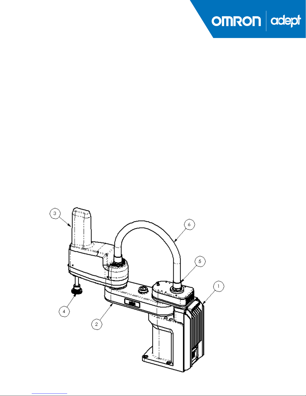
After downloading the appropriate file, and opening it, note the following part names:
1. BASE ASSY
2. INNER LINK ASSY
3. OUTER LINK ASSY
4. QUILL ASSY
5. CABLE CONNECTOR (2X)
6. FLYOVER CABLE (Note: The FLYOVER CABLE will only stay assembled in
the Solidworks native assembly, and is built in context for this purpose.
Page 2
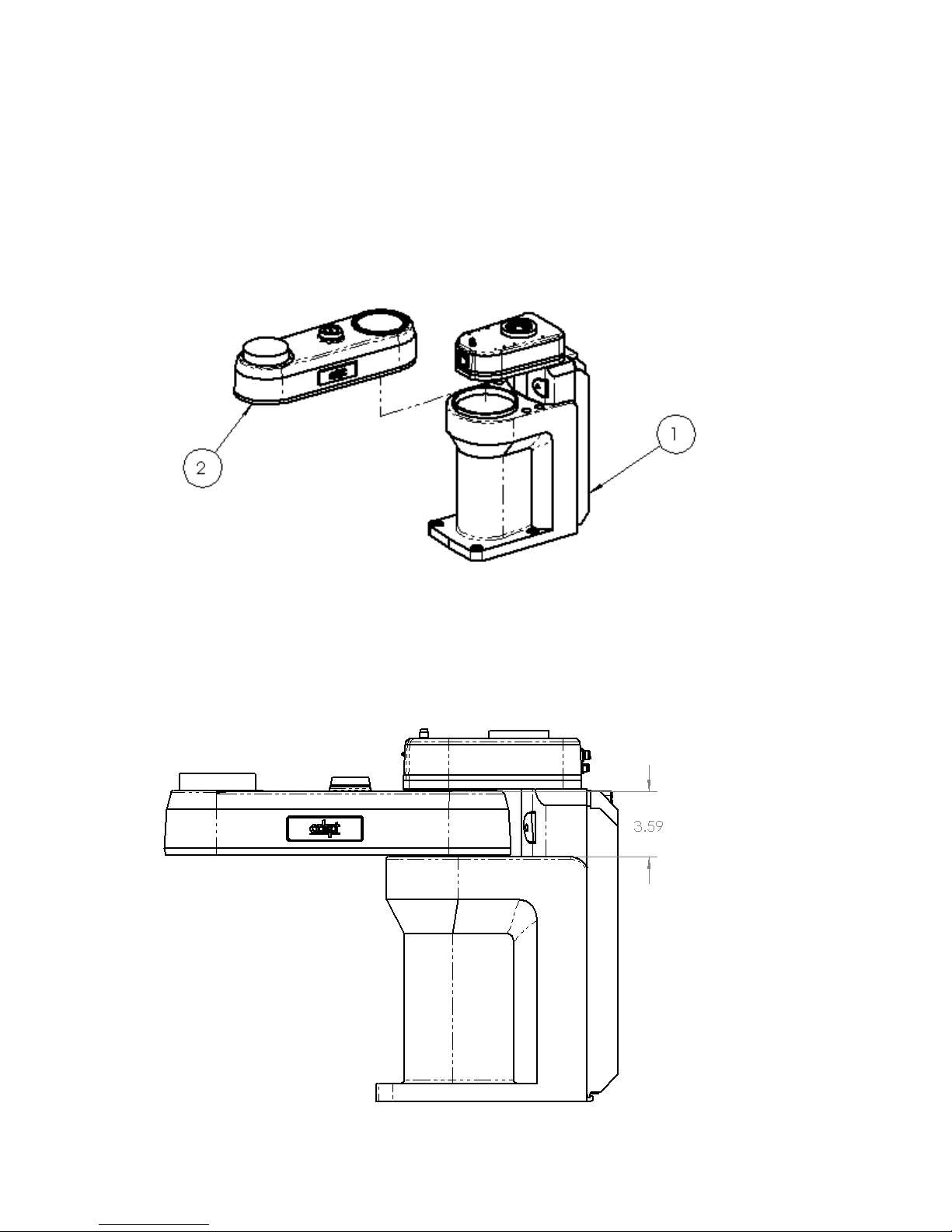
- Start by “Fixing” the BASE ASSY.
- Mate the LOWER LINK ASSY to the BASE ASSY by:
1. Concentric relationship of the BASE ASSY ring to the LOWER LINK ASSY ring
2. Distance relationship of 3.59” (91.19mm) of the upper surface of the LOWER
LINK ASSY to the upper surface of the BASE ASSY.
2
Page 3
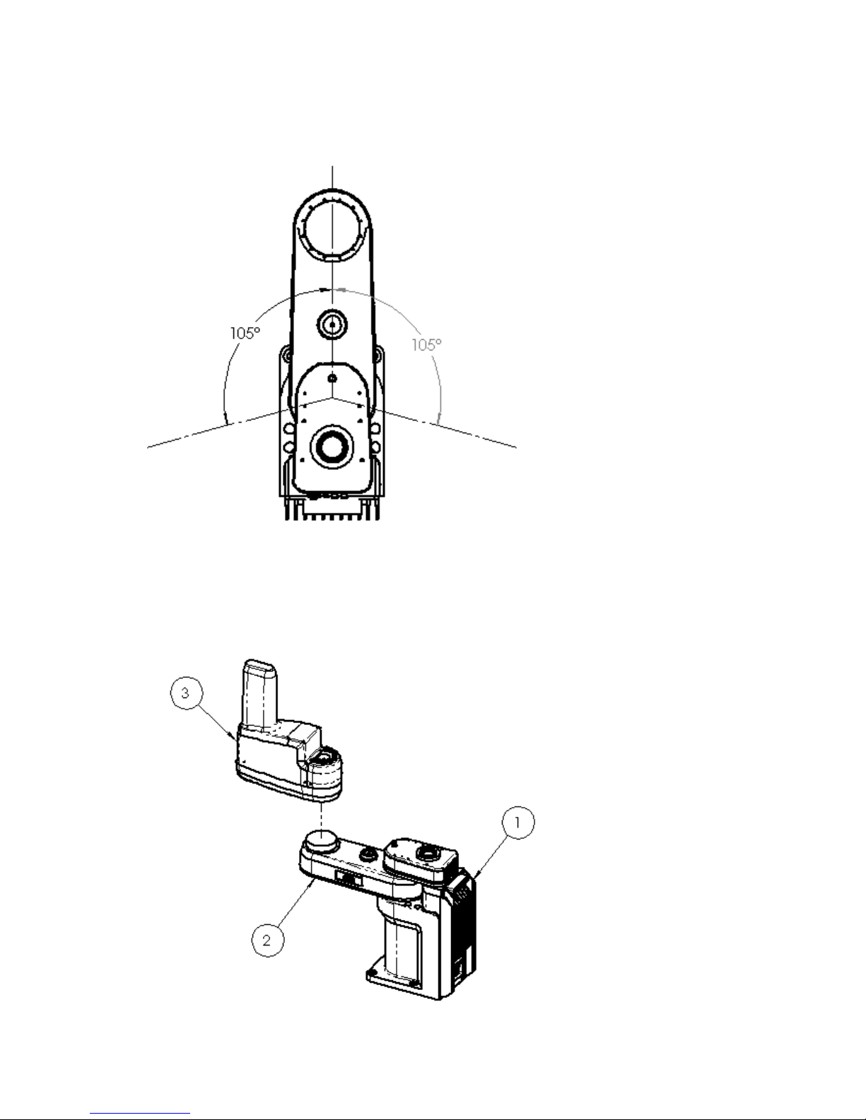
3. Angular relationship of +/- 105 degrees of the center plane of the LOWER LINK
ASSY to the center plane of the BASE ASSY.
- Mate the OUTER LINK ASSY to the LOWER LINK ASSY.
1. Concentric relationship of the LOWER LINK ASSY “boss” to the UPPER LINK
ASSY “hole.”
3
Page 4

2. Distance relationship of .272” (6.90mm) of the bottom of the OUTER LINK
ASSY to the upper surface of the LOWER LINK ASSY where the mounting
holes are located.
3. Angular relationship of +/- 150 deg. (+/- 157 deg. on the s800) of the center plane
of the OUTER LINK ASSY to the center plane of the LOWER LINK ASSY.
4
Page 5

- Mate the QUILL ASSY to the OUTER LINK ASSY.
1. Concentric relationship of the QUILL ASSY to the OUTER LINK ASSY “front
hole.”
2. Distance relationship of 6.97” – 15.24” (177mm - 387mm) of the bottom of the
QUILL ASSY to the bottom surface of the BASE ASSY, on the s800 the
Distance relationship is 7.40” – 15.67” (188mm – 398mm).
3. There is no set rotation angle due to the QUILL ASSY being able to rotate 360
deg.
5
Page 6

- Mate the CABLE CONNECTORS and the FLYOVER CABLE. Note, this part of
the assembly is only needed to check the layout for the clearance height for the
FLYOVER CABLE.
1. Concentric relationship of the CABLE CONNECTOR to the OUTER LINK and
BASE ASSY.
2. Coincident relationship of the CABLE CONNECTOR to the OUTER LINK and
BASE ASSY.
3. Concentric relationship of the long end of the FLYOVER CABLE to the CABLE
CONNECTOR attached to the BASE ASSY.
4. Coincident relationship of the long end of the FLYOVER CABLE to the inner
step on the CABLE CONNECTOR attached to the BASE ASSY.
6
Page 7

5. Coincident relationship of the center plane of the FLYOVER CABLE to the
center plane of the INNER LINK ASSY, this will allow the FLYOVER CABLE
to rotate, but not “flex” unless the original SW assembly is used.
Omron Adept Technologies, Inc.
Tel: 925-245-3400 Email: info@adept.com
omron247.com
Specifications subject to change without notice.
2016 Omron. ALL RIGHTS RESERVED. Pub Number R58I-E-01
 Loading...