

Page 1
Cobra 350 ePLC Robot
Quick Setup Guide
I592-E-01
Page 2

Copyright Notice
The information contained herein is the property of Omron Adept Technologies, Inc., and shall
not be reproduced in whole or in part without prior written approval of Omron Adept Technologies, Inc. The information herein is subject to change without notice and should not be construed as a commitment by Omron Adept Technologies, Inc. This manual is periodically
reviewed and revised.
Omron Adept Technologies, Inc., assumes no responsibility for any errors or omissions in this
document. Critical evaluation of this manual by the user is welcomed. Your comments assist
us in preparation of future documentation. Please email your comments to: techpubs@adept.com.
Copyright© 2013, 2016 by Omron Adept Technologies, Inc. All rights reserved.
Any trademarks from other companies used in this publication
are the property of those respective companies.
Printed in the United States of America
Cobra ePLC350 Quick Setup Guide, 13590-000 Rev D
Page 2 of 14
Page 3

Chapter 1: Cobra ePLC350 Robot Quick Setup
1.1 Introduction
Process Overview
This Quick Setup Guide steps you through the installation and start-up of your Cobra ePLC350
robot. The major steps are:
l
Preparation, including workcell layout and safety
l
Hardware Installation, including mounting the robot and system cable connections
l
System Start-Up, including system configuration and turning on the robot
NOTE:This guide does not apply to robot systems that include a SmartController
motion controller. Refer to the Cobra s350 Robot User's Guide for those systems.
During this process, refer also to your PLC user’s guide. The Cobra 350 Robot User's Guide is
available on the support disk.
Resources on the Support Disk
l
This guide
Resources on Omron Web Sites
On the Omron Industrial Automation web site:
On the Omron Adept web site:
1.2 Safety
l
The Cobra 350 Robot User's Guide
ia.omron.com
l
The ePLCConnect 3 Software User's Guide
l
EtherNet/IP Connection Guide (P649-E1-01)
This covers ePLC for the Omron NJ controller with Omron Adept Robots.
l
EtherNet/IP Connection Guide (P650-E1-01)
This covers ePLCIO for the Omron NJ controller with Omron Adept robots.
adept.com
l
Legacy systems communication structure pdfs
l
Legacy systems code examples
WARNING:We strictly prohibit installation or operation of
our robots without adequate safeguards according to applicable local and national standards. See Typical Workcell Layout on page 4 for a simple workcell layout.
Cobra ePLC350 Quick Setup Guide, 13590-000 Rev D
Page 3 of 14
Page 4
You must read the Robot Installation and Operation chapters in the Cobra 350 Robot User's
DC
IN
24V
GND
AC
200 240V
Ø
1
XBELTIO
XIO
Servo
ENETENET
XSYSTEM
Front Panel
T20 Pendant -
Optional
PC running
PLC Programming
Software
Safety Barrier
Restricted Area
Inside Safety
Barrier
200-240 VAC
Cobra
ePLC350 Robot
24 VDC
XUSR
eMB-40R Amplifier
Programmable
Logic
Controller (PLC)
User-Supplied
Components
STOP
R
Guide for information on safe operation of your robot system, and the Robot Safety Guide.
Refer to Installing User-Supplied Safety Equipment in the System Installation chapter of the
Cobra 350 Robot User's Guide, which provides details on connecting a user-designed E-Stop system to the XUSR connector on the robot.
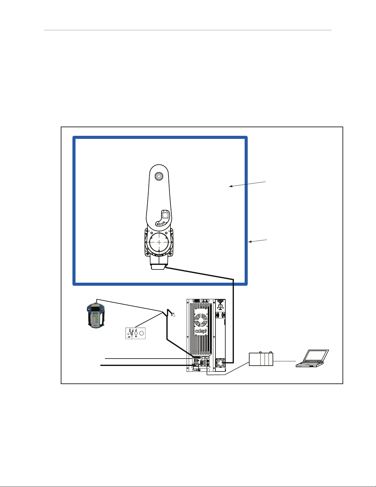
1.3 Workcell Layout
The following figure shows a simple workcell layout with a user-supplied safety barrier and
E-Stops provided by the Front Panel and optional T20 pendant.
1.3 Workcell Layout
Figure 1-1. Typical Workcell Layout
Cobra ePLC350 Quick Setup Guide, 13590-000 Rev D
Page 4 of 14
Page 5
Chapter 1: Cobra ePLC350 Robot Quick Setup
Bolts
Pallet
Bolts
Turn until it comes
into contact with
the mechanical end.
Worker B
Worker A
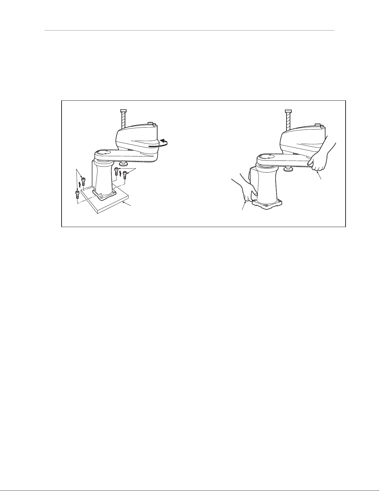
1.4 Installing the Robot
Rotate the robot outer arm before removing the shipping bolts from the pallet. This will help
prevent the robot from tipping over. Use two people to lift the robot. See the following figure.
Figure 1-2. Rotate Outer Arm, Remove Bolts, then Lift the Robot
Mounting the Robot
Mount the robot to a rigid surface that will prevent vibration and flexing during operation. We
recommend a 25 mm (1 in.) thick steel plate, mounted to a rigid steel tube frame. See the following figure for the mounting hole dimensions.
Cobra ePLC350 Quick Setup Guide, 13590-000 Rev D
Page 5 of 14
Page 6

1.4 Installing the Robot
120
120
7
17
R 1500
R 1500
144
(291 for Cabling)
4x Ø 12 Thru
2x Ø 6 H7
+0.012
0
134 ± 0.005
Units are mm
2nd axis (J2)
1st axis (J1)
3rd axis (J3)
4th axis (J4)
(-)
(+)
(+)
(+)
(+)
(-)
(-)
(-)
Figure 1-3. Mounting Hole Dimensions
Figure 1-4. Robot Movements
Cobra ePLC350 Quick Setup Guide, 13590-000 Rev D
Page 6 of 14
Page 7

Chapter 1: Cobra ePLC350 Robot Quick Setup
1.5 System Cable Connections
Open the Accessory box and locate the eAIB XSYSTEM cable. Connect the cables and peripherals as shown in the following figure. Parts and steps are covered in the following two
tables. Refer to the System Installation chapter in the Cobra 350 User’s Guide for AC specifications and wiring instructions.
Part Cable and Parts List Part # Part of: Notes
A eAIB XSYSTEM Cable Assembly 13323-000 standard, eMB-40R
B User E-Stop, Safety Gate n/a n/a user-supplied
C XUSR Jumper Plug 04736-000 13323-000 standard, eMB-40R
D Front Panel 90356-10358 standard
E Front Panel Cable 10356-10500 90356-
10358
F Front Panel Jumper Plug 10053-000 13323-000 standard, eMB-40R
G XMCP Jumper Plug 04737-000 13323-000 standard, eMB-40R
H T20 Bypass Plug 10048-000 10055-000 standard, T20
J T20 Adapter Cable 10051-003 10055-000 standard, T20
K T20 Pendant (option) 10055-000 option
L AC Power Cable (option) 04118-000 90565-010 user-supplied
M 24 VDC Power Cable (option) 04120-000 90565-010 user-supplied
N 24 VDC, 6 A Power Supply
(option)
P Ethernet Cable - PC -> PLC
(Only while programming PLC)
Q Ethernet Cable - PLC -> switch n/a n/a user-supplied
R Ethernet Cable - switch ->
SmartVisionMX
S Ethernet switch, cable n/a n/a user-supplied
04536-000 90565-010 user-supplied
n/a n/a user-supplied
n/a n/a user-supplied
standard
T Camera and cable n/a n/a option
Power Requirements
The power requirements for the SmartVision MX and the Cobra robot are covered in their
respective user guides. For 24 VDC, both can be powered by the same power supply.
NOTE:The resistance of all ground conductors must be ≤ 10 Ω.
Cobra ePLC350 Quick Setup Guide, 13590-000 Rev D
Page 7 of 14
Page 8

1.5 System Cable Connections
Step Connection Part
1 Connect eAIB XSYSTEM cable to XSYSTEM on eMB-40R. A
2 Connect a user E-Stop or Muted Safety Gate to the eAIB XSYSTEM cable XUSR
B
connector or
2a verify XUSR jumper plug is installed in eAIB XSYSTEM cable XUSR connector. C
3 Connect Front Panel cable to Front Panel and eAIB XSYSTEM cable XFP con-
D, E
nector or
3a if no Front Panel, install FP jumper on eAIB XSYSTEM cable XFP connector.
F
See NOTE after table.
4 Connect T20 adapter cable to eAIB XSYSTEM cable XMCP connector or J, K
4a if no T20, install XMCP jumper or T20 Adapter Cable with T20 bypass plug. G or
H
5 Connect user-supplied ground to robot. See robot user's guide for location. n/a
5a Connect user-supplied ground to SmartVision MX, if used. See SmartVision
n/a
MX user's guide for location.
6 Connect 200-240 VAC to AC input on eMB-40R Interface Panel; secure with
L
clamp.
7 Connect 24 VDC to DC input on Interface Panel. N,
M
7a Connect 24 VDC to SmartVision MX, if used. N,
M
8 Connect Ethernet cable from PC to PLC. P
9 Connect Ethernet cable from PLC to switch. S
9a Connect Ethernet cable from switch to eMB-40R. Q, S
9b Connect Ethernet cable from SmartVision MX, if used, to switch. R, S
10 Connect optional camera and cable to SmartVision MX, if used. T
NOTE:A front panel ships with each Cobra ePLC system, but you can choose not
to use it if you replace its functionality with equivalent circuits. That is beyond the
scope of this guide.
Cobra ePLC350 Quick Setup Guide, 13590-000 Rev D
Page 8 of 14
Page 9

Chapter 1: Cobra ePLC350 Robot Quick Setup
DC
IN
24 V
GND
AC
200 -
240 V
Ø
1
XBELTIO
XIO
Servo
ENETENET
XSYSTEM
eMB-40R for
Cobra ePLC350
Robot
24 VDC, 6 A
Power Supply
200-240 VAC
10 A
single-phase
AC Power
Cable
DC Power
Cable
Front Panel
Cable
Front Panel
User-Supplied PC
running PLC
Programming Software
T20 Adapter
Cable
XMCP Jumper Plug
XMCP
XFP
XUSR
XUSR Jumper Plug
eAIB
XSYSTEM
Cable
Robot Interface
Panel
XUSR for:
- User E-Stop/Safety Gate
- Muted Safety Gate
The Jumper Plug is required if
neither of these is used
Ethernet from
PC to PLC
T20 Bypass Plug
User-Supplied
Ground Wire
T20 Pendant (option)
Either T20 Pendant,T20 Bypass Plug, or
XMCP Jumper Plug must be used
2
3
4a
A
B
G
H
J
4a
4
4
1
5
6
7
9
8
L
M
Q
P
E
K
D
N
3
85 - 264 VAC
Universal
Input
Ethernet from
PLC to eMB-40R
FP Jumper Plug
F
Either Front Panel or
FP plug must be used
3a
2a
C
Ethernet from eMB-40R
to SmartVision MX
R
9b
9a
User-supplied
Switch
SmartVision MX (option)
Camera
(option)
User-Supplied
Ground Wire
5a
7a
M
T
10
DC Power
Cable
S
PLC
DC
IN
24V
GND
AC
200 240V
Ø
1
XBELTIO
XIO
Servo
ENETENET
XSYSTEM
1.6 Configuration
The user-supplied PLC and the Cobra ePLC350 robot are connected either through a shared
network or via a user-supplied Ethernet cable.
When the Cobra ePLC350 robot is powered on and waiting for a PLC connection, the eMB-40R
status panel will display its IP address, two digits at a time.
The format will be:
IP xxx-xxx-xxx-xxx OK
Figure 1-5. Configuration with Vision
Cobra ePLC350 Quick Setup Guide, 13590-000 Rev D
Page 9 of 14
Page 10

1.6 Configuration
NOTE:If you can use the eMB-40R’s default IP address, then you can skip the ACE
software installation completely.
Installing ACE Software
ACE is used to change the IP address of the robot and for troubleshooting. You install the ACE
software onto your PC from the ACE disk.
NOTE:You will have to restart the PC after installing ACE software.
Setting the Robot IP Address
Configure the IP address of the Cobra ePLC350 robot using ACE software.
1.
Connect the PC and the eMB-40R, either through a shared network or with an Ethernet
cable between them.
2.
Start the ACE software.
3.
Click the Detect and Configure button, circled in the following figure.
Figure 1-6. Detect and Configure Button
The IP address detection and configuration window will open. The ACE software will show
the IP address of any controllers it detects. See the following figure.
Cobra ePLC350 Quick Setup Guide, 13590-000 Rev D
Page 10 of 14
Page 11

Chapter 1: Cobra ePLC350 Robot Quick Setup
Figure 1-7. IP Addresses Detected
4.
You can change the IP address and subnet mask in the Desired Address and Desired
Subnet fields, if needed.
5.
Click OK. The ACE software will ask you to wait for the controller to reboot.
Configuring the Omron PLC
Refer to the EtherNet/IP Connection Guide (P649-E1-01) for configuring the Omron PLC to
work with Omron Adept robots. Refer to Resources on Omron Web Sites on page 3.
Using your PLC software, set the IP address for the PLC to connect to on the robot.
Enabling High Power
The details of enabling high power to the robot are covered in the EtherNet/IP Connection
Guide (P649-E1-01).
Once high power is enabled, the Robot Status Panel displays ON, and the Robot Status LED is
green, with a fast blink.
1.7 Finding Additional Information
Installing Optional Equipment
For details on installing optional equipment, see the following topics in the Optional Equipment Installation chapter of the Cobra 350 Robot User’s Guide:
l
Installing end-effectors
l
Connecting user air and electrical lines to user connection panel
l
Mounting external equipment on the robot
l
Mounting the robot solenoid option kit
Cobra ePLC350 Quick Setup Guide, 13590-000 Rev D
Page 11 of 14
Page 12

1.7 Finding Additional Information
NOTE:For dimensions and specifications, see Technical Specifications in the Cobra
350 Robot User’s Guide.
System Operation
For details on system operation, see the following topics in the System Operation chapter of the
Cobra 350 Robot User’s Guide:
l
Robot Status LED Indicator
l
Status panel fault codes
l
Brake Release button (located above the diagnostic panel). To move Joint 3 manually,
press the Brake Release button.
l
Connecting digital I/O on the XIO connector at the robot interface panel
l
Connecting a user-designed E-Stop System
Cobra ePLC350 Quick Setup Guide, 13590-000 Rev D
Page 12 of 14
Page 13

Page 14

OMRON Corporation Industrial Automation Company
Kyoto, JAPAN
Regional Headquarters
OMRON EUROPE B.V.
Wegalaan 67-69, 2132 JD Hoofddorp
The Netherlands
Tel: (31)2356-81-300/Fax: (31)2356-81-388
OMRON ASIA PACIFIC PTE. LTD.
No. 438A Alexandra Road # 05-05/08 (Lobby 2),
Alexandra Technopark,
Singapore 119967
Tel: (65) 6835-3011/Fax: (65) 6835-2711
Contact: www.ia.omron.com
OMRON ELECTRONICS LLC
2895 Greenspoint Parkway, Suite 200 Hoffman Estates,
IL 60169 U.S.A.
Tel: (1) 847-843-7900/Fax: (1) 847-843-7787
OMRON ADEPT TECHNOLOGIES, INC.
4550 Norris Canyon Road, Suite 150, San Ramon, CA 94583 U.S.A.
Tel: (1) 925-245-3400/Fax: (1) 925-960-0590
OMRON (CHINA) CO., LTD.
Room 2211, Bank of China Tower, 200 Yin Cheng Zhong Road,
PuDong New Area, Shanghai, 200120, China
Tel: (86) 21-5037-2222/Fax: (86) 21-5037-2200
Authorized Distributor:
© OMRON Corporation 2016 All Rights Reserved.
In the interest of product improvement,
specifications are subject to change without notice.
Cat. No. I592-E-01
Printed in USA
0416
 Loading...