

Page 1

Programmable Multi-Axis Controller
Startup Guide
for DirectPWM Interface
CK3W-AX1313
CK3W-AX2323
O047-E1-01
Page 2

NOTE
• All rights reserved. No part of this publication may be reproduced, stored in a retrieval system, or transmitted, in
any form, or by any means, mechanical, electronic, photocopying, recording, or otherwise, without the prior
written permission of OMRON.
• No patent liability is assumed with respect to the use of the information contained herein.
Moreover, because OMRON is constantly striving to improve its high-quality products, the information contained
in this manual is subject to change without notice.
• Every precaution has been taken in the preparation of this manual. Nevertheless, OMRON assumes no responsibility for errors or omissions.
Neither is any liability assumed for damages resulting from the use of the information contained in this publication.
Trademarks
• Microsoft, Windows, Windows Vista, Excel, and Visual Basic are either registered trademarks or trademarks of
Microsoft Corporation in the United States and other countries.
• EtherCAT® is registered trademark and patented technology, licensed by Beckhoff Automation GmbH, Germany.
Other company names and product names in this document are the trademarks or registered trademarks of their
respective companies.
Copyrights
• Microsoft product screen shots reprinted with permission from Microsoft Corporation.
• This product incorporates certain third party software. The license and copyright information associated with this
software is available at http://www.fa.omron.co.jp/nj_info_e/.
Page 3

Sections in this Manual
1
2
3
Summary of Materials
Target Equipment and Device Configuration
DirectPWM Interface Connection Procedure
1
2
3
Sections in this Manual
CK3M-series Startup Guide DirectPWM Interface (O047)
3
Page 4

CONTENTS
CONTENTS
Sections in this Manual ........................................................................................... 3
Related Manuals....................................................................................................... 5
Revision History
....................................................................................................... 6
Terms and Definitions.............................................................................................. 7
Precautions .............................................................................................................. 8
Section 1 Summary of Materials
1-1 Summary of Materials............................................................................................................1-2
1-1-1 Intended Audience
......................................................................................................................1-2
Section 2 Target Equipment and Device Configuration
2-1 Device Configuration.............................................................................................................2-2
Section 3 DirectPWM Interface Connection Procedure
3-1 Work Flow...............................................................................................................................3-2
3-2 Controller Setting Preparations
3-2-1 Creation of a New Project ...........................................................................................................3-3
3-2-2 Controller Initial Setting ...............................................................................................................3-4
3-3 Various Equipment Connection............................................................................................3-6
3-4 Various Controller Settings...................................................................................................3-8
3-4-1 Notes List ..................................................................................................................................3-13
3-5 Confirmation of Settings ..................................................................................................... 3-17
3-6 Motor Tuning ........................................................................................................................3-19
3-6-1 Open Loop Test.........................................................................................................................3-19
3-6-2 Current Loop Gain Setting ........................................................................................................3-20
3-6-3 Bandwidth Automatic Setting ....................................................................................................3-21
3-6-4 Manual Setting of Bandwidth ....................................................................................................3-23
3-6-5 Feed-Forward Value Setting......................................................................................................3-25
3-6-6 Checking of Operation and Creation of Tuning Parameter Project...........................................3-27
............................................................................................3-3
4
CK3M-series Startup Guide DirectPWM Interface (O047)
Page 5

Related Manuals
To safely utilize the system, obtain a manual or user's guide for each device and piece of equipment,
confirm their content, including “Safety Precautions”, “Precautions for Safe Use”, and other precautions related to safety, and then proceed with use.
The manuals for OMRON Corporation (hereafter, “OMRON”) and Delta Tau Data Systems Inc. (hereafter “DT”) are as shown below.
Related Manuals
Manufac-
turer
OMRON O036
DT O014 --- Power PMAC User's Manual
DT O015 --- Power PMAC Software Reference Manual
DT O016 --- Power PMAC IDE User's Manual
Cat. No. Model Manual Name
CK3M-£
-
CK3W
£
Programmable Multi-Axis Controller Hardware User's Manual
CK3M-series Startup Guide DirectPWM Interface (O047)
5
Page 6

O047-E1-01
Revision code
Revision History
Revision History
A manual revision code appears as a suffix to the catalog number on the front and back covers.
Revision
code
01 July 2019 Original production
Revision date Revised content
6
CK3M-series Startup Guide DirectPWM Interface (O047)
Page 7

Terms and Definitions
Terms Descriptions and Definitions
PMAC This is the acronym for Programmable Multi-Axis Controller.
Power PMAC IDE This is computer software that is used to configure the Motion Controller, create
user programs, and perform monitoring.
DirectPWM This is a proprietary interface method developed by Delta Tau Data Systems, Inc.
for connecting Servo Drives.
Digital Quadrature Encod-erThis is a type of encoder that outputs pulse signals.
Terms and Definitions
CK3M-series Startup Guide DirectPWM Interface (O047)
7
Page 8

Precautions
Precautions
• For actual system construction, check the specifications for each device and piece of equipment that
makes up the system, use a method with sufficient margin for ratings and performance, and adopt
safety circuits and other safety measures to minimize risks even if a breakdown occurs.
• To safely utilize the system, obtain a manual or user's guide for each device and piece of equipment
that makes up the system, confirm and understand their content, including “Safety Precautions”,
“Precautions for Safe Use”, and other precautions related to safety, and then proceed with use.
• The customer must check all regulations, laws, and rules that are applicable to the system themselves.
• Copying, duplication, or redistribution of part or all of these materials without the permission of OMRON Corporation is prohibited.
• The content listed in these materials is valid as of July 2019.
The content listed in these materials may be changed without notice for purposes of improvement.
The marks used in these materials are defined as follows.
Precautions for Correct Use
Precautions on what to do and what not to do to ensure correct operation and performance.
Additional Information
Additional information to read as required.
This information is provided to increase understanding and make operation easier.
8
CK3M-series Startup Guide DirectPWM Interface (O047)
Page 9

Summary of Materials
This section lists a summary of these materials.
1
1
1-1 Summary of Materials
1-1-1 Intended Audience.......................................................................................... 1-2
.................................................................................... 1-2
CK3M-series Startup Guide DirectPWM Interface (O047)
1-1
Page 10

1 Summary of Materials
1-1
1-1-1
Summary of Materials
This document summarizes the procedures and confirmation methods for connecting a Servo Drive
that is compatible with the DirectPWM interface method to the OMRON Programmable Multi-Axis Controller CK3M-££££ (hereinafter called “Controller”).
By understanding the setting content and setting procedure points described in Section 3 DirectPWM
Interface Connection Procedure on page 3-1, you can configure the Controller to send commands
to the DirectPWM interface-capable Servo Drive and control Servomotors.
The connection procedure in this document describes an example when a digital quadrature encoder
is used to perform position and velocity feedback for CK3W-AX1313£.
*1.
If CK3W-AX2323£ is used, the same DirectPWM interface as CK3W-AX1313£
setting needs to be changed because a different type of encoder needs to be connected. Refer to the following documents for encoder settings.
• Startup Guide Sinusoidal Encoder
• Startup Guide for SSI/Mitutoyo/EnDat 2.1/2.2 Serial Encoder
Intended Audience
This guide is intended for the following personnel, who must also have knowledge of electrical systems (electrical or the equivalent).
• Personnel in charge of introducing F
• Personnel in charge of designing FA systems.
• Personnel in charge of installing and maintaining FA systems.
• Personnel in charge of managing FA systems and facilities.
A systems.
*1
is available but the encoder
Also, this guide is intended for personnel who understand the contents described in the DT manual.
1-2
CK3M-series Startup Guide DirectPWM Interface (O047)
Page 11

2
Target Equipment and Device
Configuration
This section lists the target equipment and system configurations for connections in
these materials.
2-1 Device Configuration
..................................................................................... 2-2
2
CK3M-series Startup Guide DirectPWM Interface (O047)
2-1
Page 12
Programmable Multi-Axis Controller
CK3M-CPU1£1
CK3W-AX1313£
CK3W-PD048
CK3W-TER11
CK3W-CAED03A
CK3W-CAAD0££A
R88ACAKA0££S
Servo Drive
Servomotor
Coupling
Digital
Quadrature
Encoder
S8VK-£
Ethernet
cable
Windows PC
Power PMAC IDE
2 Target Equipment and Device Configuration
2-1
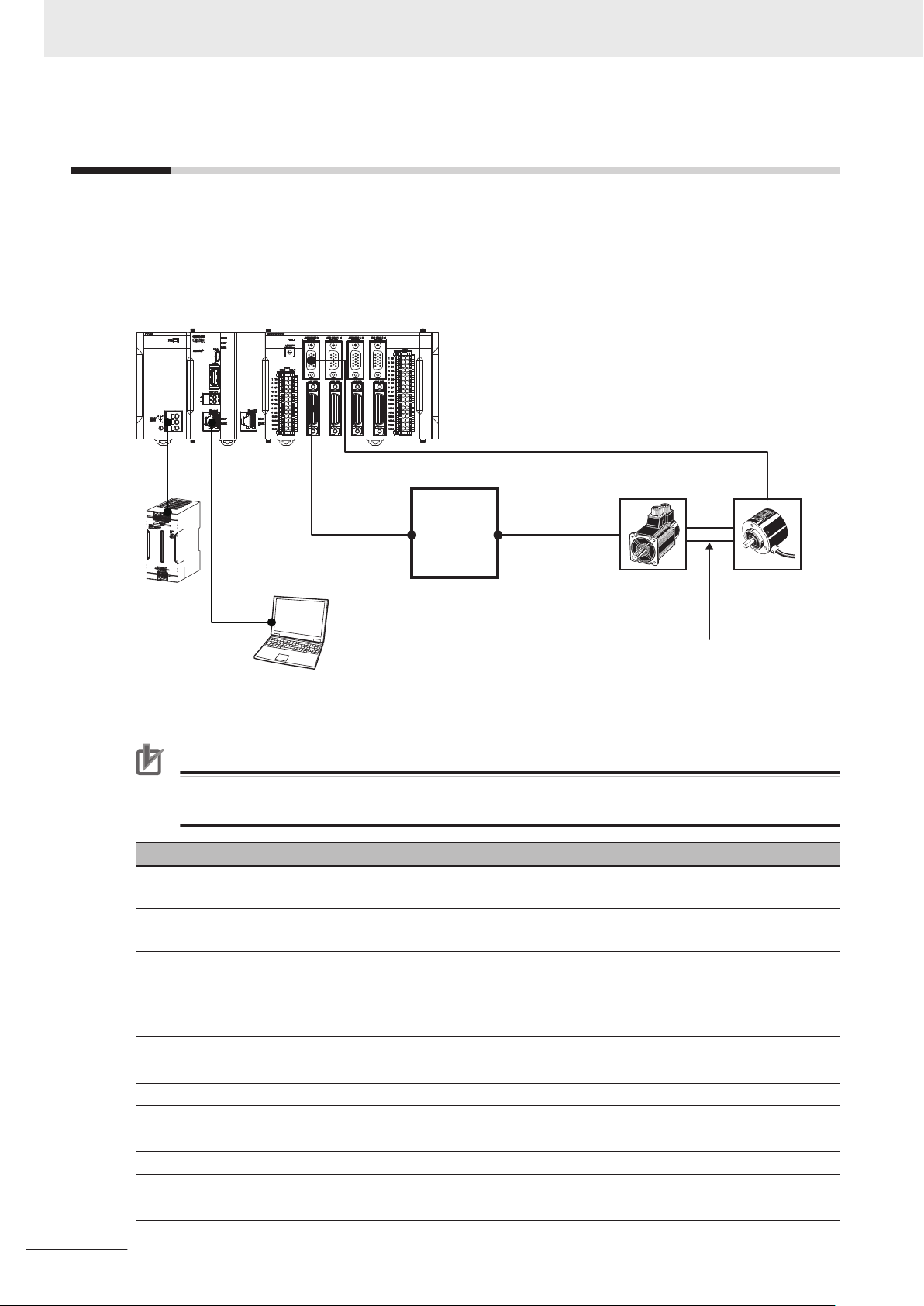
Device Configuration
The configuration devices for reproducing the connection procedures in this document are shown below.
This example shows a DirectPWM interface setting using the configuration where the digital quadrature encoder is connected to the output axis of a motor. This configuration is used only to show a setting example and is not a standard configuration.
Precautions for Correct Use
Always secure a Servomotor and encoder. Starting the motor that is not secured leads to a failure.
Manufacturer Name Model Version
OMRON Programmable Multi-Axis Controller
CPU Unit
OMRON Programmable Multi-Axis Controller
Axis Interface Unit
OMRON Programmable Multi-Axis Controller
Power Supply Unit
OMRON Programmable Multi-Axis Controller
End Cover
OMRON DirectPWM Cable
OMRON Motor Cable
OMRON Encoder Cable CK3W-CAES03A --Servotronix Servo Drive CDHD-0032APB0 --OMRON Servomotor R88M-K05030T --OMRON Digital Quadrature Encoder E6B2-CWZ1X --OMRON Coupling E69-C68B
OMRON Switching Power Supply
CK3M-CPU1£1
CK3W-AX1313£
CK3W-PD048 ---
CK3W-TER11 ---
CK3W-CAAD0££A
R88A-CAKA0££S
S8VK-£
Version 2.5.2 or
later
---
---
---
---
2-2
CK3M-series Startup Guide DirectPWM Interface (O047)
Page 13

2 Target Equipment and Device Configuration
Manufacturer Name Model Version
--- Windows PC --- --DT Power PMAC Setting Tool Power PMAC IDE Version 4.3 or
later
2-1 Device Configuration
2
CK3M-series Startup Guide DirectPWM Interface (O047)
2-3
Page 14

2 Target Equipment and Device Configuration
2-4
CK3M-series Startup Guide DirectPWM Interface (O047)
Page 15

3
DirectPWM Interface Connection
Procedure
3
This section describes the procedures for connecting the Controller and Servo Drive,
and operating the motion control equipment with the DirectPWM interface. The de-
scription assumes that the Controller is set to factory default.
3-1 W
3-2 Controller Setting Preparations.................................................................... 3-3
3-3 Various Equipment Connection.................................................................... 3-6
3-4 Various Controller Settings........................................................................... 3-8
3-5 Confirmation of Settings .............................................................................3-17
3-6 Motor Tuning................................................................................................. 3-19
ork Flow ....................................................................................................... 3-2
3-2-1 Creation of a New Project............................................................................... 3-3
3-2-2 Controller Initial Setting................................................................................... 3-4
3-4-1 Notes List...................................................................................................... 3-13
3-6-1 Open Loop Test ............................................................................................ 3-19
3-6-2 Current Loop Gain Setting ............................................................................ 3-20
3-6-3 Bandwidth Automatic Setting........................................................................ 3-21
3-6-4 Manual Setting of Bandwidth ........................................................................ 3-23
3-6-5 Feed-Forward Value Setting ......................................................................... 3-25
3-6-6 Checking of Operation and Creation of Tuning Parameter Project............... 3-27
CK3M-series Startup Guide DirectPWM Interface (O047)
3-1
Page 16

3 DirectPWM Interface Connection Procedure
3-1
Work Flow
The procedures for connecting the Controller and Servo Drive, and operating the motion control equipment with the DirectPWM interface, are shown below.
3-2 Controller Setting Preparations on page
3-3
▼
Creation of a New Project on page 3-3
3-2-1
▼
3-2-2 Controller Initial Setting on page 3-
▽
4
3-3 Various Equipment Connection on page
3-6
▽
3-4 Various Controller Settings on page 3-8
▽
3-5 Confirmation of Settings on page 3-17
▽
▼
▼
▼
▼
▼
on page
▼
3-19
3-20
3-25
3-6 Motor T
3-6-1 Open Loop Test on page 3-19
3-6-2 Current Loop Gain Setting on page
3-6-3 Bandwidth Automatic Setting on page 3-21
3-6-4 Manual Setting of Bandwidth on page 3-23
3-6-5 Feed-Forward V
3-6-6 Checking of Operation and Creation of Tuning Parameter
Project on page 3-27
uning on page
alue Setting
Perform the Controller setting preparations.
Perform connection and wiring for each device.
Perform the Controller settings.
Check that the settings up to here are correct.
Use Power PMAC IDE tuning tools to tune
the motor.
3-2
CK3M-series Startup Guide DirectPWM Interface (O047)
Page 17
3 DirectPWM Interface Connection Procedure
3-2
3-2-1
Controller Setting Preparations
Perform the Controller setting preparations.
Install the Power PMAC IDE on the PC beforehand.
Creation of a New Project
Follow the procedure below to create a new project.
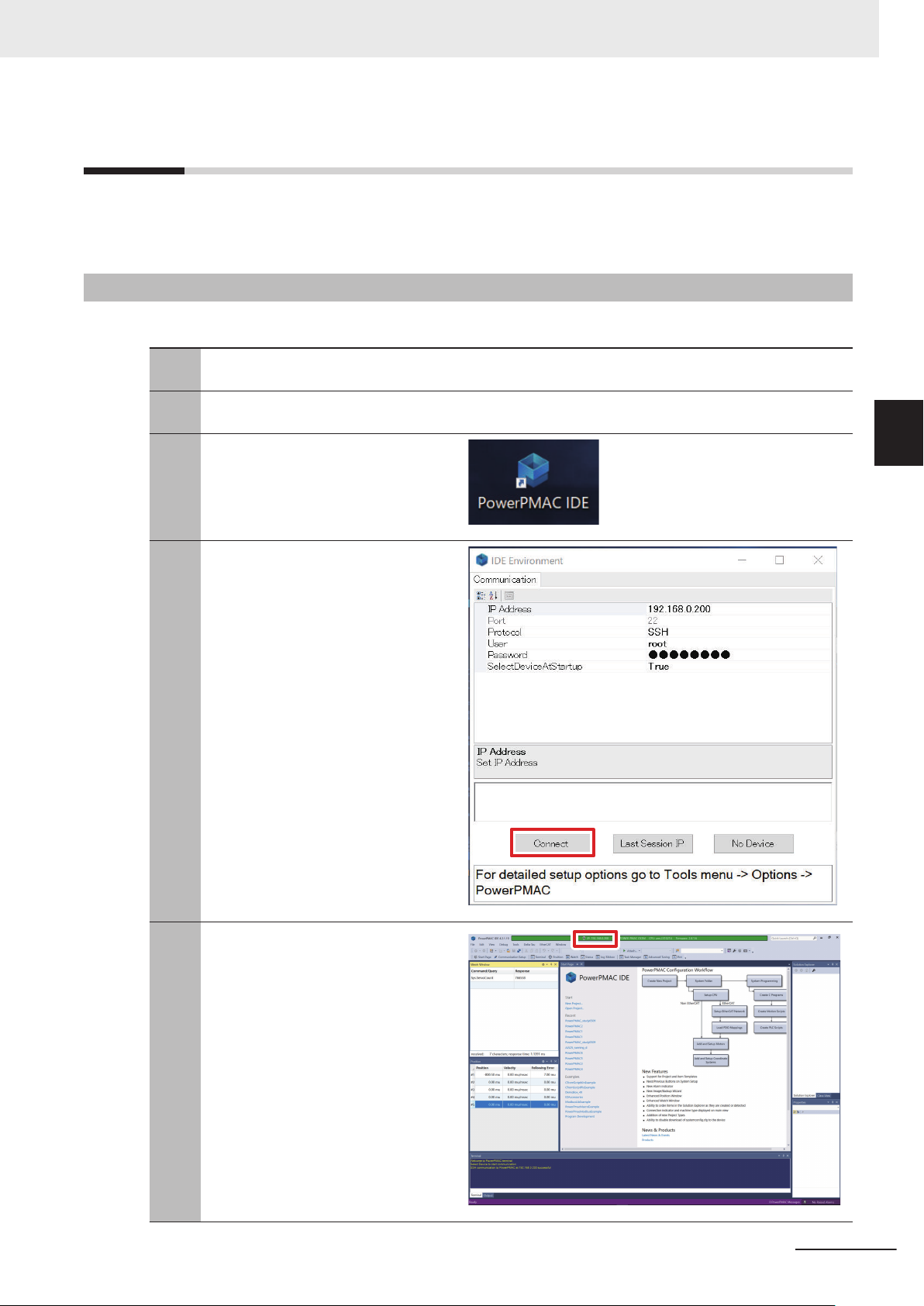
Connect the Controller and computer
1
with an Ethernet cable.
Turn ON the power supply to the Con-
2
troller
.
Start up Power PMAC IDE.
3
• If a dialog for checking access rights
is displayed at the time of startup, select the option for starting up.
The Communication screen is dis-
4
played, so specify the IP address of the
Controller to be connected to, and click
the Connect button.
• The default IP address for the Con-
troller is "192.168.0.200".
• If necessary
address to "192.168.0.X".
, change the Windows IP
3-2 Controller Setting Preparations
3
3-2-1 Creation of a New Project
Power PMAC IDE starts up, and the
5
Controller will come online.
CK3M-series Startup Guide DirectPWM Interface (O047)
3-3
Page 18

3 DirectPWM Interface Connection Procedure
From the File menu, select New ‒
6
Project.
3-2-2
Input a project name and save destina-
7
tion, and select the OK button.
Controller Initial Setting
Follow the procedure below to perform the initial settings for the Controller.
Precautions for Correct Use
Since all memory is cleared by the initial settings, be sure to save any data remaining in the
Controller that you may need.
3-4
Type the $$$*** command from the T
1
minal, and set the Controller to the factory default state.
er-
CK3M-series Startup Guide DirectPWM Interface (O047)
Page 19

Type the save command in the Power
2
PMAC IDE T
• When the save is completed,
Completed" is displayed in the Terminal.
Type the $$$ command in the Power
3
PMAC IDE Terminal.
• When the reset is completed,
"PowerPMAC Reset complete
played in the Terminal.
erminal.
"Save
" is dis-
3 DirectPWM Interface Connection Procedure
3-2 Controller Setting Preparations
3
3-2-2 Controller Initial Setting
CK3M-series Startup Guide DirectPWM Interface (O047)
3-5
Page 20
CK3W-AX1313£
CK3W-CAED03A
CK3W-CAAD0££A
R88ACAKA0££S
Servo Drive
CDHD-0032APB0
Servomotor
Coupling
Digital
Quadrature
Encoder
d
a
b
c
3 DirectPWM Interface Connection Procedure
3-3
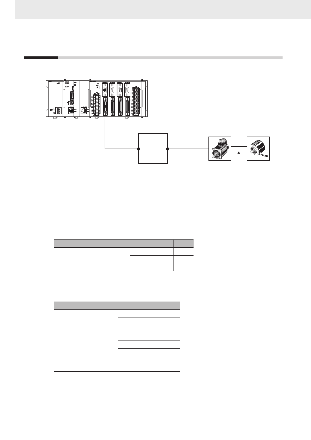
Various Equipment Connection
The following diagram shows the connection between the axis interface unit and various equipment.
Follow the instructions below to connect a, b, c, and d shown in the diagram above.
3-6
a. Connection between the Controller and Servo Drive
Use the following dedicated cables to connect the CK3W-AX1313£
amplifier connector to the Ser-
vo Drive C2 connector.
Manufacturer Name Model Length
OMRON DirectPWM Cable CK3W-CAAD009A 0.9 m
CK3W-CAAD018A 1.8 m
CK3W-CAAD036A 3.6 m
b. Connection between the Servo Drive and Servomotor
Use the following dedicated cables to connect the Servo Drive P2 connector to the Servomotor
connector.
Manufacturer Name Model Length
OMRON Motor Cable R88A-CAKA003S 3 m
R88A-CAKA005S 5 m
R88A-CAKA010S 10 m
R88A-CAKA015S 15 m
R88A-CAKA020S 20 m
R88A-CAKA030S 30 m
R88A-CAKA040S 40 m
R88A-CAKA050S 50 m
c. Connection between the Servomotor and Encoder
Use the following coupling to connect the rotary axes of the Servomotor and digital quadrature encoder
Coupling: E69-C68B
.
CK3M-series Startup Guide DirectPWM Interface (O047)
Page 21
CK3W-CAES03A
Encoder Cable
E6B2-CWZ1X
Pulse Encoder
Black
Red
Black
Red
Black
Red
Black
Red
Brown
Blue
Black
Black/red stripes
White
White/red stripes
Orange
Orange/red stripes
Power supply (+Vcc)
0 V (common)
Output phase A
Output phase AOutput phase B
Output phase BOutput phase Z
Output phase Z-
11
13
1
6
2
7
3
8
Blue
Blue
Pink
Pink
Green
Green
Orange
Orange
Encoder Power Supply (+5VDC)
Encoder Power Supply (GND)
Encoder A+
Encoder AEncoder B+
Encoder BEncoder C+
Encoder C-
Signal SignalColor
Pin
No.
Cable
color
Mark
3 DirectPWM Interface Connection Procedure
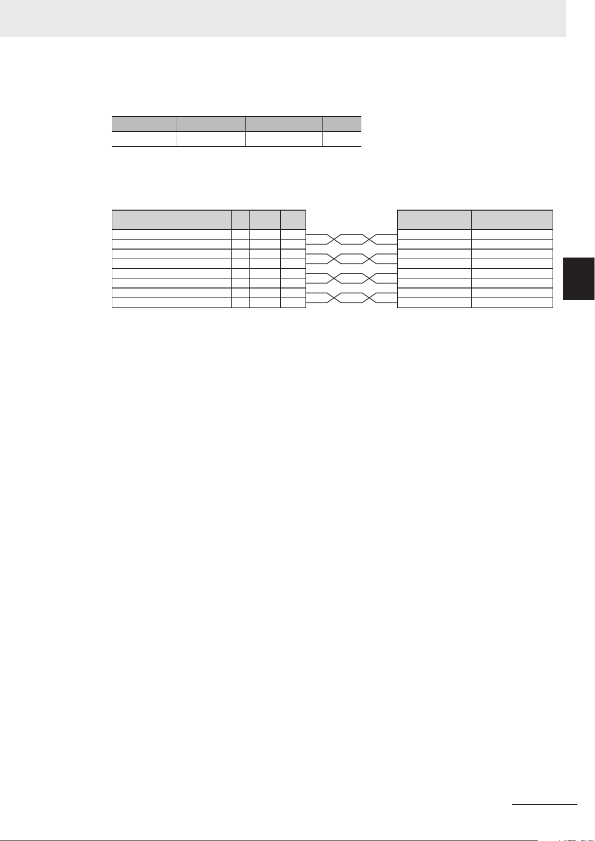
d. Wiring between the Controller and Encoder
Use the following dedicated cable to connect CK3W-AX1313£
Manufacturer Name Model Length
OMRON Encoder Cable CK3W-CAES03A 3 m
Follow the wiring diagram below to connect the dedicated cable (CK3W-CAES03A) to the digital
quadrature encoder.
to the digital quadrature encoder.
3-3 Various Equipment Connection
3
CK3M-series Startup Guide DirectPWM Interface (O047)
3-7
Page 22

3 DirectPWM Interface Connection Procedure
3-4
Various Controller Settings
Follow the procedure below to perform the settings for the Controller when a Servomotor is controlled
by the DirectPWM interface and digital quadrature encoder.
Precautions for Correct Use
• For items to be written in the global definitions.pmh in step 2 in the following procedure, set
appropriate values depending on the motor and Servo Drive used. If the set value is not appropriate, an excessive current flows, which may cause the equipment to fail.
Refer to Notes *24 through *26 in 3-4-1 Notes List on page 3-13 for the settings.
• If Motor[1].IaBias and Motor[1].IbBias are set to other than 0 in the following step 9 and 11,
the motor may rotate. Make sure that no problem occurs and the equipment is safe if the motor rotates before the setting.
Open the global definitions.pmh under
1
PMAC Script Language ‒ Global
Includes in the Solution Explorer
.
3-8
CK3M-series Startup Guide DirectPWM Interface (O047)
Page 23

3 DirectPWM Interface Connection Procedure
Write the text on the right to the global
2
definitions.pmh.
• Refer to 3-4-1 Notes List on page
3-13 for details on setting items with
Notes *1 through *30 shown in the
text on the right.
Sys.WpKey = $AAAAAAAA
//global setting
Gate3[0].PhaseServoDir = 0;
Gate3[0].PhaseFreq = 10000; //10kHz
Gate3[0].ServoClockDiv = 9; //1kHz
Sys.PhaseOverServoPeriod = 0.1;
Sys.ServoPeriod = 1;
//Encoder Setting
EncTable[1].Type = 1; //*1
EncTable[1].pEnc = Gate3[0].Chan[0].ServoCapt
.a; //*2
EncTable[1].ScaleFactor = 1/exp2(8); //*3
Gate3[0].EncClockDiv = 5; //3.125MHz
Gate3[0].Chan[0].EncCtrl = 7; //*4
//DirectPWM AD Convertor setting
Gate3[0].AdcAmpStrobe = $fffffc; //*5
Gate3[0].AdcAmpHeaderBits = 2; //*6
Gate3[0].AdcAmpClockDiv = 5; //3.125MHz
//DirectPWM PWM output setting
Gate3[0].Chan[0].PwmFreqMult = 2; //*7
Gate3[0].Chan[0].PwmDeadTime = 15; //*8
Gate3[0].Chan[0].PackInData = 2; //*9
Gate3[0].Chan[0].PackOutData = 1; //*10
3-4 Various Controller Settings
3
3-4-1 Notes List
CK3M-series Startup Guide DirectPWM Interface (O047)
3-9
Page 24

3 DirectPWM Interface Connection Procedure
Sys.WpKey=$0
//Motor setting
Motor[1].ServoCtrl = 1; //Enable the Motor[1]
.
Motor[1].PhaseCtrl = 1; //Enable the commutat
ion task.
Motor[1].pPhaseEnc = Gate3[0].Chan[0].PhaseCa
pt.a; //*11
Motor[1].PhasePosSf = 2048/(256*2000*4/5); //
*12
Motor[1].PwmSf = 13458; //*13
Motor[1].PhaseOffset = 683; //*14
Motor[1].AmpFaultLevel = 1; //*15
Motor[1].pLimits = 0; //Disable the Overtrave
l limit.
Motor[1].WarnFeLimit = 4000; //*16
Motor[1].FatalFeLimit = 8000; //*17
Motor[1].pAmpEnable = Gate3[0].Chan[0].OutCtr
l.a;
Motor[1].pAmpFault = Gate3[0].Chan[0].Status.
a;
Motor[1].pCaptFlag = Gate3[0].Chan[0].Status.
a;
Motor[1].pCaptPos = Gate3[0].Chan[0].HomeCapt
.a;
Motor[1].pEncCtrl = Gate3[0].Chan[0].OutCtrl.
a;
Motor[1].pEncStatus = Gate3[0].Chan[0].Status
.a;
Motor[1].pMasterEnc = EncTable[1].a;
Motor[1].CurrentNullPeriod = 1; //*18
Motor[1].pEnc = EncTable[1].a //*19
Motor[1].pEnc2 = EncTable[1].a //*20
Motor[1].pDac = Gate3[0].Chan[0].Pwm[0].a; //
*21
Motor[1].pAdc = Gate3[0].Chan[0].AdcAmp[0].a;
//*22
Motor[1].AdcMask = $FFFC0000; //*23
Motor[1].MaxDac = 28377 * 3.33 / 11.25; //*24
Motor[1].I2tSet = 28377 * 1.1 / 11.25; //*25
Motor[1].I2tTrip = (Motor[1].MaxDac * Motor[1
].MaxDac -Motor[1].I2tSet * Motor[1].I2tSet)
* 3; //*26
Motor[1].AbsPhasePosOffset = 400; //*27
Motor[1].PhaseFindingDac = 4000; //*28
Motor[1].PhaseFindingTime = 1000; //*29
Motor[1].PowerOnMode = 1; //*30
Motor[1].InPosBand = 100;
3-10
// Setting Coordinate System
&1
#1->x
&1%100;
CK3M-series Startup Guide DirectPWM Interface (O047)
Page 25

Right click on the Solution Explorer
$$$
3
project name at the upper right of the
Power PMAC IDE screen, select Build
and Download All Programs, and execute Build and Download.
3 DirectPWM Interface Connection Procedure
3-4 Various Controller Settings
3
Make sure that there are no errors in
4
the Output Window.
• If the transfer failed, check the con-
tent of the error in the Output Window
. If there is a program error, fix
the program.
Type the save command in the Power
5
PMAC IDE T
• When the save is completed,
Completed" is displayed in the Terminal.
Type the $$$ command in the T
6
erminal.
3-4-1 Notes List
"Save
erminal.
To determine a sign for
7
Motor[1].PhaseOffset, paste
Motor[1].PhasePos, Motor[1].IaBias,
and Motor[1].IbBias in the Watch window
.
CK3M-series Startup Guide DirectPWM Interface (O047)
3-11
Page 26

3 DirectPWM Interface Connection Procedure
8
9
10
Type the #1out0 command in the T
minal.
Set Motor[1].IaBias=200 and
Motor[1].IbBias=0 in the Terminal.
Check the Motor[1].PhasePos value in
the W
atch window
.
er-
11
12
Set Motor[1].IbBias=200 in the Terminal.
• Motor[1].IaBias
Check the Motor[1].PhasePos value in
the W
atch window
remains 200.
.
3-12
CK3M-series Startup Guide DirectPWM Interface (O047)
Page 27

3 DirectPWM Interface Connection Procedure
13
14
15
Type Motor[1].IaBias=0
Motor[1].IbBias=0
return the phase A and B bias currents
to 0.
If the Motor[1].PhasePos value decreases when values in step 10 and 12
are compared, set the sign of
Motor[1].PhaseOffset to + (addition); if
the value increases, set the sign to −
(subtraction).
and
in the Terminal to
• Since the value decreases in this ex-
ample, set
Motor[1].PhaseOffset=683 in the
global definitions.pmh.
If a sign of Motor[1].PhaseOffset
needs to be changed, change the
sign in the global definitions.pmh and
perform download again following the
procedure in step 3 through 6.
Manually rotate the coupling that connects the motor to encoder and check
that the desired scale is applied to the
current position in the Position window
• The
EncTable[1].ScaleFactor value
is set to 8000 counts per rotation in
this example, so 8000 mu is added to
the current position per rotation.
3-4 Various Controller Settings
3
3-4-1 Notes List
.
Precautions for Correct Use
If the save command is not successfully completed, the transferred project is not saved in the
Controller. If the power to the Controller is switched OFF without the project being saved, the
transferred project is destroyed.
Additional Information
To change the counting direction of the digital quadrature encoder (clockwise/counterclockwise), change the sign of the following set values to write in the global definitions.pmh in step 2
to − (subtraction).
• EncT
able[1].ScaleFactor
• Motor[1].PhasePosSf
3-4-1
Notes List
The following table shows details on notes (description of set items) in step 2.
CK3M-series Startup Guide DirectPWM Interface (O047)
3-13
Page 28

Set value :
1
2
(32 bits -24 bits )
f
PWM
=
Gate3[0].Chan[0].PwmFreqMult+1
2
× f
IntPhase
f
IntPhase
: Internal phase clock frequency
Sf =
2048 × Number of motor pole pairs
256 × Encoder resolution × Encoder multiplication setting
3 DirectPWM Interface Connection Procedure
No. Set item Set value Description
*1 EncTable[1].Type 1 Enable EncTable[1] as single-word (32 bits) read.
*2 EncTable[1].pEnc Gate3[0].Chan[0].S
ervoCapt.a
*3 EncTable[1].Scale-
1/exp2(8) Calculate a scale factor set value in accordance with the following for-
Factor
Assign the digital quadrature encoder data to EncTable[1].
mula because EncT
able[1] is 32 bits and Gate3[0].Chan[0].ServoCapt
(digital quadrature encoder data) is 24 bits.
*4 Gate3[0].Chan[0].E
ncCtrl
*5 Gate3[0].Ad-
cAmpStrobe
*6
Gate3[0].AdcAmpHeaderBits
*7 Gate3[0].Chan[0].P
wmFreqMult
*8 Gate3[0].Chan[0].P
wmDeadTime
*9 Gate3[0].Chan[0].P
ackInData
*10 Gate3[0].Chan[0].P
ackOutData
*11 Motor[1].pPha-
seEnc
*12 Motor[1].Phase-
PosSf
7 Set the digital quadrature encoder conversion method to four multipli-
cation, counterclockwise.
$fffffc Specify AMP Strobe Word. If $fffffc is set, the Controller is compatible
with all AD converters.
2 Set the header length of analog to digital conversion data to 2 bits.
Set it depending on the Servo Drive specifications.
2 Set the PWM frequency to 15 kHz. Calculate the PWM frequency in
accordance with the formula below.
Make sure that the value is 40 kHz or less and the same as the Servo
Drive maximum input frequency or less.
15 Set the PWM signal dead time to 800 ns. Calculate the dead time in
accordance with the formula below.
Dead time = 0.0533 μs × Gate3[0].Chan[0].PwmDeadTime
Set it depending on the Servo Drive specifications.
2 AdcAmp compression: Enabled
If the digital current loop is implemented, enable data compression that
improves algorithm efficiency
.
1 Enable PWM/DAC compression. If the commutation and digital current
loop are calculated, enable data compression that improves algorithm
.
Gate3[0].Chan[0].P
efficiency
Use the digital quadrature encoder for commutation position feedback.
haseCapt.a
2048/
(256*2000*4/5)
Set a scale factor (Sf) of the commutation position (angle). Use the following formula to calculate the scale factor if 24 bits digital quadrature
encoder (Gate3[0].Chan[0].ServoCapt) is assigned to 32 bits EncTable[1] as this example.
3-14
Set it depending on the specifications of equipment used.
The following shows parameters for equipment used in this example.
(32 bits - 24 bits)
256: 2
= 256
Encoder resolution: 2000 pulses per rotation
Encoder multiplication: 4 multiplication
Number of motor pole pairs: 5 pairs (10 poles)
CK3M-series Startup Guide DirectPWM Interface (O047)
Page 29

MaxDac =
Cos (30°) × 32767 × Maximum instantaneous current
Servo driver ADC full-range current
3 DirectPWM Interface Connection Procedure
No. Set item Set value Description
*13 Motor[1].PwmSf 13458 Set a scale factor for PWM output. The full range is 16384.
The scale factor is normally set to less than 95% of the full range so
that PWM waveform cannot reach the duty cycle of 0% or 100%. It is
set to approximately 82% in this example.
Set it depending on the Servo Drive specifications.
*14 Motor[1].PhaseOff-
set
*15 Motor[1].AmpFault-
Level
*16 Motor[1].WarnFeLi-
mit
*17 Motor[1].FatalFeLi-
mit
*18 Motor[1].Current-
NullPeriod
*19 Motor[1].pEnc EncTable[1].a Specify the digital quadrature encoder as an address used for loop
*20
*21 Motor[1].pDac Gate3[0].Chan[0].P
*22 Motor[1].pAdc Gate3[0].Chan[0].A
*23 Motor[1].AdcMask $FFFC0000 Specify which bit of 32 bits current feedback word is used as the actual
*24 Motor[1].MaxDac 28377*3.33/11.25 Set an instantaneous current limit value (root mean square: RMS).
Motor[1].pEnc2 EncTable[1].a Specify the digital quadrature encoder as the address used for loop
683 For a three-phase motor, set to 683 or −683.
1 Specify a logic of AMP Fault detection. Set it depending on the Servo
Drive specifications.
0: Negative logic is used to detect AMP Fault.
1: Positive logic is used to detect AMP Fault.
4000 The status bit Motor[1].AmpWarn is set when the positional deviation
exceeds this value.
The value for a half-rotation of the motor is set in this example. Set it
depending on applications used.
8000 The motor is killed and the status bit Motor[1].FeFatal is set when the
positional deviation exceeds this value.
The value for a half-rotation of the motor is set in this example. Set it
depending on applications used.
1 Motor[1].IaBias and Motor[1].IbBias are set in
Motor[1].PhaseFindingStep=1 during phase search.
feedback to control the motor position.
able[1] in Notes *2
able[1] in Notes *2
, and use a smaller
wm[0].a
dcAmp[0].a
The digital quadrature encoder is assigned to EncT
in this example.
feedback to control the motor velocity.
The digital quadrature encoder is assigned to EncT
in this example.
Assign DirectPWM to the motor command output register.
Specify the DirectPWM interface AD converter as an AD converter
used for digital current feedback.
current value.
The 14 bits AD converter is set in this example. Set it depending on the
Servo Drive specifications.
Compare those of the Servo Drive and the motor
value. The motor has a smaller value in this example.
Use the following formula for calculation.
3-4 Various Controller Settings
3
3-4-1 Notes List
CK3M-series Startup Guide DirectPWM Interface (O047)
Determine parameters depending on the equipment used.
The following shows parameters for equipment used in this example.
Maximum instantaneous current for R88M-K05030T: 4.7 A (p-p)/
3.33 A (RMS)
ADC full range current for CDHD-0032APB0: 11.25 A (RMS)
√2 =
3-15
Page 30

I2tSet =
Cos (30°) × 32767 × Rated current
Servo driver ADC full-range current
3 DirectPWM Interface Connection Procedure
No. Set item Set value Description
*25 Motor[1].I2tSet 28377*1.1/11.25 Set a rated current limit value (RMS). Compare those of the Servo
Drive and the motor, and use a smaller value. The motor has a smaller
value in this example.
Use the following formula for calculation.
Determine parameters depending on the equipment used.
The following shows parameters for equipment used in this example.
Rated current for R88M-K05030T: 1.1 A (RMS)
1.25 A (RMS)
*26 Motor[1].I2tTrip (Motor[1].Max-
Dac*Motor[1].MaxDac − Motor[1].I2tSet*Motor[1].I2tSet)*3
*27 Motor[1].AbsPha-
sePosOf
*28 Motor[1].PhaseFin-
dingDac
*29 Motor[1].PhaseFin-
dingTime
Motor[1].PowerOn-
*30
Mode
fset
400 Specify the minimum operation that is considered to be an ef
4000 Set the size of phase-sequence current that is output to each motor
1000 Set duration of each step during phase search. Adjust it depending on
1 1: Enables the motor after phase search.
ADC full range current for CDHD-0032APB0: 1
Set a motor integrated current limit. Use the following formula for cal-
culation.
I2tTrip = (MaxDAC2 + IdCmd2 − I2tSet2) × allowable time (second)
Allowable time for R88M-K05030T
phase search. Although the commutation cycle (2048) 1/4 = 512 (90°)
is ideal, it is set to approximately 80% in this example considering that
problems such as friction can prevent the operation.
If Motor[1].PhaseFindingStep=1 displacement is smaller than this
value during phase search, the phase search is considered to be failed
by Power PMAC.
phase in phase search. Adjust it depending on the equipment used.
the equipment used.
The following duration is used in this example.
Duration = Servo cycle × Motor[1].PhaseFindingTime = 1 ms × 1000 =
1000 ms
0: Kills the motor after phase search.
: 3 seconds
ficient
3-16
CK3M-series Startup Guide DirectPWM Interface (O047)
Page 31

3 DirectPWM Interface Connection Procedure
3-5
Confirmation of Settings
Follow the procedure below to check that the settings up to here are correct.
Type the
1
Motor[1].PhaseFindingStep=1 com-
mand from the T
phase search.
• The Motor[1].PhaseFindingStep
value changes to 1, 6, 7, and 0.
When the phase search succeeds,
the Motor[1].ClosedLoop and
Motor[1].PhaseFound
change from 0 to 1.
In addition, the Motor[1].New[0].Pos
value becomes larger than the
Motor[1].AbsPhasePosOffset set
value. The AMP ENAB 0 LED is
turned on at that time.
erminal to perform a
values
*1
3-5 Confirmation of Settings
3
Type the #1 out1 command from the
2
T
erminal.
Make sure that the motor is rotating. In
3
addition, check that the Position window Position value is increasing in the
positive direction.
• If the motor does not rotate even af-
ter typing the #1 out1 command, increase the value gradually as #1
out2, #1 out3.
Type the kill command from the Termi-
4
nal to stop the motor.
*1. If Motor[1].PhaseFound does not indicate 1, the phase search has failed. Check if the set value is appro-
priate.
The following shows some examples of set value adjustment when a phase search fails.
CK3M-series Startup Guide DirectPWM Interface (O047)
3-17
Page 32

3 DirectPWM Interface Connection Procedure
• If the Motor[1].New[0].Pos value is smaller than the Motor[1].AbsPhasePosOffset set value after
phase search, increase the Motor[1].PhaseFindingDac value. In addition, check that the
Motor[1].PhasePosSf set value is appropriate.
• If an error occurs in I2tFault status during phase search, decrease the value of
Motor[1].PhaseFindingDac or
• If the Motor[1].New[0].Pos value indicates − (subtraction) after phase search, change signs of
Motor[1].PhasePosSf and EncTable[1].ScaleFactor.
Motor[1].PhaseFindingTime.
3-18
CK3M-series Startup Guide DirectPWM Interface (O047)
Page 33

3 DirectPWM Interface Connection Procedure
3-6
3-6-1
Motor Tuning
Follow the procedure below to use Power PMAC IDE tuning tools for tuning the motor.
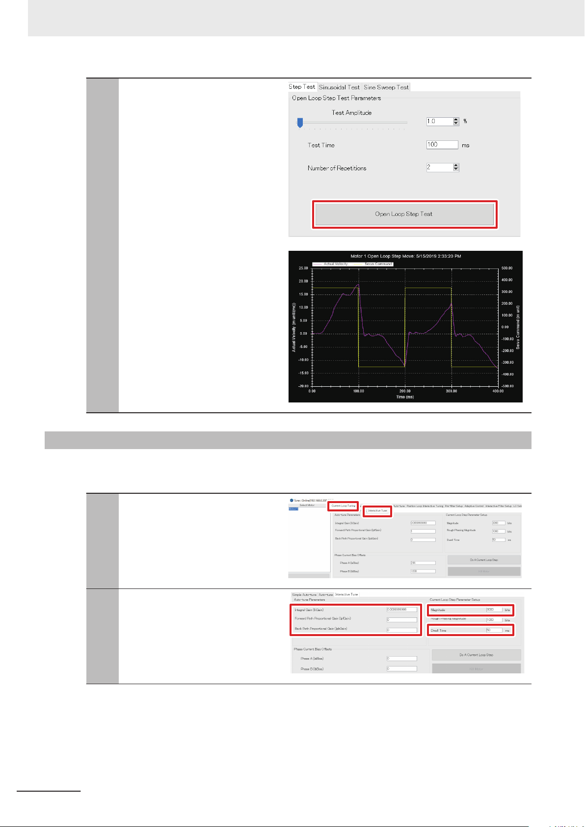
Open Loop Test
Follow the procedure below to operate the motor in an open loop, and check that each setting is correct.
From the T
1
lect
Tune screen, and then select Open
LoopTest ‒ Step Test.
ools menu in Delta Tau, se-
Advanced Tuning to open the
3-6 Motor Tuning
3
3-6-1 Open Loop Test
Set the following tuning parameters.
2
T
est Amplitude: 1.0%
est Time: 100 ms
T
Number of Repetitions: 2
*1. If the motor does not rotate, set a
large value.
*1
CK3M-series Startup Guide DirectPWM Interface (O047)
3-19
Page 34
3 DirectPWM Interface Connection Procedure
Click the Open Loop Step T
3
• The motor is performing reciprocating
operation and the test result on the
right is displayed.
• If the motor does not rotate, change
the T
est Amplitude
large value.
• The test result is when the Test
Amplitude parameter is set to 8.0%.
parameter to a
est
button.
3-6-2
Current Loop Gain Setting
Follow the procedure below to perform current loop gain settings and adjust them to achieve desired
response characteristics.
In the Tune screen, select Current
1
Loop Tuning ‒
Set the following parameters.
2
IliGain: 0.0099999998 (Default)
IpfGain: 0
IpbGain: 0
Magnitude: 3000 bits
Dwell T
ime: 50 ms
Interactive Tune.
3-20
CK3M-series Startup Guide DirectPWM Interface (O047)
Page 35

Click the Do A Current Loop Step but-
3
ton.
3 DirectPWM Interface Connection Procedure
• The current step response is dis-
played.
Adjust the IliGain, IpfGain, and
4
IpbGain parameters to achieve the de-
sired response characteristics.
3-6 Motor Tuning
3
3-6-3 Bandwidth Automatic Setting
3-6-3
• If the startup response is slow, in-
crease the IliGain parameter
• If the overshooting or vibration is
large, increase the IpfGain or
IpbGain parameter.
• Increase each gain parameter gradu-
ally starting from a small value.
.
Bandwidth Automatic Setting
Follow the procedure below to use the auto-tuning function for setting the servo loop bandwidth automatically.
CK3M-series Startup Guide DirectPWM Interface (O047)
3-21
Page 36

3 DirectPWM Interface Connection Procedure
In the Tune screen, select Position
1
Loop Auto-tune ‒ Advance Autotune.
Set the following parameters.
2
Amplifier Type: Direct PWM
Auto Select Bandwidth: Select the
check box.
Encoder Resolution: 8000 cts/rev
Excitation Magnitude: 8.0%
Iteration No.: 2
*1.
Select the value rotated in the open
loop in step 3 in 3-6-1 Open Loop
T
on page 3-19.
est
*1
• For Encoder Resolution, set the
pulse counts per one motor rotation.
In this example, 2000 pulses per rotation of the digital quadrature encoder is set to be multiplied by four, so
Encoder Resolution indicates 8000.
Click the Auto-tune Motor button.
3
If the message on the right appears,
4
click the Y
button.
es
3-22
CK3M-series Startup Guide DirectPWM Interface (O047)
Page 37

If the screen on the right appears, click
5
the Implement button.
Check that the Recommended Gains
6
values are applied to Current Gains,
and then click the OK button.
3 DirectPWM Interface Connection Procedure
3-6 Motor Tuning
3
3-6-4 Manual Setting of Bandwidth
3-6-4
Manual Setting of Bandwidth
Follow the procedure below to set a more appropriate bandwidth, while monitoring the step response
characteristic.
Select Position Loop Interactive
1
T
Set the following parameters.
2
Step Size: 2500 mu
‒ Step in the Tune screen.
uning
CK3M-series Startup Guide DirectPWM Interface (O047)
3-23
Page 38

3 DirectPWM Interface Connection Procedure
Click the Step Move button.
3
Check the step response characteristic.
4
If the target position has not been
5
reached, return to the Advance Autotune screen, and set an even larger
value for
Click the Recalculate button.
6
If the screen on the right appears, click
7
the Implement button.
Bandwidth.
3-24
CK3M-series Startup Guide DirectPWM Interface (O047)
Page 39

Check that the Recommended Gains
8
values are applied to Current Gains,
and then click the OK button.
Return to step 1 and repeat the proce-
9
dure until the desired responsiveness is
obtained.
3 DirectPWM Interface Connection Procedure
3-6 Motor Tuning
3
3-6-5 Feed-Forward Value Setting
3-6-5
Feed-Forward Value Setting
Follow the procedure below to set a more appropriate bandwidth, while monitoring the step response
characteristic.
In the Tune screen, select Position
1
Loop Auto-tune ‒ Advance Autotune, and insert checks into Velocity
FF and Acceleration FF
Click the Recalculate button.
2
.
CK3M-series Startup Guide DirectPWM Interface (O047)
3-25
Page 40

3 DirectPWM Interface Connection Procedure
If the screen on the right appears, click
3
the Implement button.
Check that the Recommended Gains
4
values are applied to Current Gains,
and then click the OK button.
Select Position Loop
5
InteractiveT
and set the following parameters.
Move Size: 2500 mu
Move Time: 500 ms
Left Axis: Velocity
Right Axis: Following Error
Click the Parabolic V
6
ton.
Check the parabolic response charac-
7
teristic of velocity
uning ‒
Parabolic Vel.
elocity Move
.
but-
3-26
CK3M-series Startup Guide DirectPWM Interface (O047)
Page 41

If Following Error has a positive corre-
8
lation to the velocity
If it has a reverse correlation, make
Kvff smaller.
, make
3 DirectPWM Interface Connection Procedure
Kvff larger.
3-6 Motor Tuning
9
10
Click the Parabolic Velocity Move
ton again.
• Repeat this until the correlation of
Following Error to the velocity disappears.
In the same way, if Following Error
has a correlation to Acceleration,
Position, etc., increase or decrease the
Kaff and Kfff values.
but-
3
3-6-6 Checking of Operation and Creation of Tuning Parameter Project
3-6-6
CK3M-series Startup Guide DirectPWM Interface (O047)
Checking of Operation and Creation of Tuning Parameter Project
Follow the procedure below to check operations and create a tuned parameter project.
3-27
Page 42

3 DirectPWM Interface Connection Procedure
Type the
1
Motor[1].PhaseFindingStep=1 com-
mand from the T
phase search.
• The Motor[1].PhaseFindingStep
value changes to 1, 6, 7, and 0.
• When the phase search succeeds,
the Motor[1].ClosedLoop and
Motor[1].PhaseFound values
change from 0 to 1. In addition, the
Motor[1].New[0].Pos value becomes larger than the
Motor[1].AbsPhasePosOffset set
value. The AMP ENAB 0 LED is
turned on at that time.
erminal to perform a
Type the #1 j+ command from the Ter-
2
minal.
Make sure that the motor is rotating. In
3
addition, confirm that the #1 V
value is around 32 in the Position win-
.
dow
• Velocity depends on
Motor[1].JogSpeed (32 by default).
Type the kill command from the T
4
nal to stop the motor
.
elocity
ermi-
3-28
CK3M-series Startup Guide DirectPWM Interface (O047)
Page 43

Open the global definitions.pmh under
5
PMAC Script Language ‒ Global
Includes in the Solution Explorer
3 DirectPWM Interface Connection Procedure
.
3-6 Motor Tuning
3
3-6-6 Checking of Operation and Creation of Tuning Parameter Project
Add the gain values obtained from tun-
6
ing to the global definitions.pmh.
Open the pp_startup.txt under
7
Configuration in the Solution Explorer.
Motor[1].IiGain = ***
Motor[1].IpfGain = ***
Motor[1].IpbGain = ***
Motor[1].Servo.Kp = ***
Motor[1].Servo.Kvfb = ***
Motor[1].Servo.Kaff = ***
Motor[1].Servo.Kvff = ***
Write the phase search implementation
8
command shown on the right.
CK3M-series Startup Guide DirectPWM Interface (O047)
Motor[1].PhaseFindingStep = 1
3-29
Page 44

3 DirectPWM Interface Connection Procedure
Select the project and execute Build
9
and Download.
• Refer to step 3 through 6 in 3-4 V
ous Controller Settings on page
for the Build and Download method.
• As shown in step 5 and 6, gains can
be downloaded on PMAC as a program if you write gains in the global
definitions.pmh.
• As shown in step 7 and 8, the phase
search is automatically performed after the power is turned ON or reset to
enable Motor[1] if you write the
phase search implementation command in the pp_startup.txt.
ari-
3-8
3-30
CK3M-series Startup Guide DirectPWM Interface (O047)
Page 45

Page 46

OMRON Corporation Industrial Automation Company
Kyoto, JAPAN
Contact: www.ia.omron.com
Regional Headquarters
OMRON EUROPE B.V.
Wegalaan 67-69, 2132 JD Hoofddorp
The Netherlands
Tel: (31)2356-81-300/Fax: (31)2356-81-388
OMRON ASIA PACIFIC PTE. LTD.
No. 438A Alexandra Road # 05-05/08 (Lobby 2),
Alexandra Technopark,
Singapore 119967
Tel: (65) 6835-3011/Fax: (65) 6835-2711
OMRON ELECTRONICS LLC
2895 Greenspoint Parkway, Suite 200
Hoffman Estates, IL 60169 U.S.A.
Tel: (1) 847-843-7900/Fax: (1) 847-843-7787
OMRON (CHINA) CO., LTD.
Room 2211, Bank of China Tower,
200 Yin Cheng Zhong Road,
PuDong New Area, Shanghai, 200120, China
Tel: (86) 21-5037-2222/Fax: (86) 21-5037-2200
Authorized Distributor:
© OMRON Corporation 2019 All Rights Reserved.
In the interest of product improvement,
specifications are subject to change without notice.
Cat. No. O047-E1-01
0719
 Loading...