

Page 1

OPERATION MANUAL
Cat. No. W396-E1-03
SYSMAC CJ Series
CJ1W-TC@@@
Temperature Control Units
Page 2

CJ1W-TC@@@
Temperature Control Units
Operation Manual
Revised December 2005
Page 3

iv
Page 4

v
Notice:
OMRON products are manufactured for use according to proper procedures by a qualified operator
and only for the purposes described in this manual.
The following conventions are used to indicate and classify precautions in this manual. Always heed
the information provided with them. Failure to heed precautions can result in injury to people or damage to property.
!DANGER Indicates an imminently hazardous situation which, if not avoided, will result in death or
serious injury. Additionally, there may be severe property damage.
!WARNING Indicates a potentially hazardous situation which, if not avoided, could result in death or
serious injury. Additionally, there may be severe property damage.
!Caution Indicates a potentially hazardous situation which, if not avoided, may result in minor or
moderate injury, or property damage.
OMRON Product References
All OMRON products are capitalized in this manual. The word “Unit” is also capitalized when it refers to
an OMRON product, regardless of whether or not it appears in the proper name of the product.
The abbreviation “Ch,” which appears in some displays and on some OMRON products, often means
“word” and is abbreviated “Wd” in documentation in this sense.
The abbreviation “PLC” means Programmable Controller. “PC” is used, however, in some Programming Device displays to mean Programmable Controller.
Visual Aids
The following headings appear in the left column of the manual to help you locate different types of
information.
Note Indicates information of particular interest for efficient and convenient opera-
tion of the product.
1,2,3... 1. Indicates lists of one sort or another, such as procedures, checklists, etc.
OMRON, 2001
All rights reserved. No part of this publication may be reproduced, stored in a retrieval system, or transmitted, in any form, o
r
by any means, mechanical, electronic, photocopying, recording, or otherwise, without the prior written permission o
f
OMRON.
No patent liability is assumed with respect to the use of the information contained herein. Moreover, because OMRON is constantly striving to improve its high-quality products, the information contained in this manual is subject to change without
notice. Every precaution has been taken in the preparation of this manual. Nevertheless, OMRON assumes no responsibility
for errors or omissions. Neither is any liability assumed for damages resulting from the use of the information contained in
this publication.
Page 5

vi
Page 6

vii
TABLE OF CONTENTS
PRECAUTIONS . . . . . . . . . . . . . . . . . . . . . . . . . . . . . . . . . . . xv
1 Intended Audience . . . . . . . . . . . . . . . . . . . . . . . . . . . . . . . . . . . . . . . . . . . . . . . . . . . . . . . . xvi
2 General Precautions . . . . . . . . . . . . . . . . . . . . . . . . . . . . . . . . . . . . . . . . . . . . . . . . . . . . . . . xvi
3 Safety Precautions. . . . . . . . . . . . . . . . . . . . . . . . . . . . . . . . . . . . . . . . . . . . . . . . . . . . . . . . . xvi
4 Operating Environment Precautions . . . . . . . . . . . . . . . . . . . . . . . . . . . . . . . . . . . . . . . . . . . xvii
5 Application Precautions . . . . . . . . . . . . . . . . . . . . . . . . . . . . . . . . . . . . . . . . . . . . . . . . . . . .xviii
6 Conformance to EC Directives . . . . . . . . . . . . . . . . . . . . . . . . . . . . . . . . . . . . . . . . . . . . . . . xxi
SECTION 1
Features and System Configuration . . . . . . . . . . . . . . . . . . . 1
1-1 Introduction and Features . . . . . . . . . . . . . . . . . . . . . . . . . . . . . . . . . . . . . . . . . . . . . . . . . . . 2
1-2 System Configuration . . . . . . . . . . . . . . . . . . . . . . . . . . . . . . . . . . . . . . . . . . . . . . . . . . . . . . 6
1-3 Comparison to C200H Temperature Control Units . . . . . . . . . . . . . . . . . . . . . . . . . . . . . . . 10
SECTION 2
Specifications and Functions . . . . . . . . . . . . . . . . . . . . . . . . . 11
2-1 Specifications . . . . . . . . . . . . . . . . . . . . . . . . . . . . . . . . . . . . . . . . . . . . . . . . . . . . . . . . . . . . 12
2-2 Application Procedure. . . . . . . . . . . . . . . . . . . . . . . . . . . . . . . . . . . . . . . . . . . . . . . . . . . . . . 18
2-3 Part Names and Functions. . . . . . . . . . . . . . . . . . . . . . . . . . . . . . . . . . . . . . . . . . . . . . . . . . .21
2-4 Wiring . . . . . . . . . . . . . . . . . . . . . . . . . . . . . . . . . . . . . . . . . . . . . . . . . . . . . . . . . . . . . . . . . . 25
2-5 Data Exchange with the CPU Unit . . . . . . . . . . . . . . . . . . . . . . . . . . . . . . . . . . . . . . . . . . . . 29
2-6 Data Ranges . . . . . . . . . . . . . . . . . . . . . . . . . . . . . . . . . . . . . . . . . . . . . . . . . . . . . . . . . . . . . 49
SECTION 3
Settings Required for Temperature Control . . . . . . . . . . . . 51
3-1 Setting the Input Type . . . . . . . . . . . . . . . . . . . . . . . . . . . . . . . . . . . . . . . . . . . . . . . . . . . . . . 52
3-2 Selecting the Temperature Units . . . . . . . . . . . . . . . . . . . . . . . . . . . . . . . . . . . . . . . . . . . . . . 53
3-3 Setting the Data Format . . . . . . . . . . . . . . . . . . . . . . . . . . . . . . . . . . . . . . . . . . . . . . . . . . . . 53
3-4 Selecting the Control Operation (Forward/Reverse). . . . . . . . . . . . . . . . . . . . . . . . . . . . . . . 54
3-5 Selecting PID Control or ON/OFF Control . . . . . . . . . . . . . . . . . . . . . . . . . . . . . . . . . . . . . 55
3-6 Setting the Control Period. . . . . . . . . . . . . . . . . . . . . . . . . . . . . . . . . . . . . . . . . . . . . . . . . . . 55
3-7 Setting the Set Point . . . . . . . . . . . . . . . . . . . . . . . . . . . . . . . . . . . . . . . . . . . . . . . . . . . . . . . 56
3-8 Using ON/OFF Control. . . . . . . . . . . . . . . . . . . . . . . . . . . . . . . . . . . . . . . . . . . . . . . . . . . . .56
3-9 Setting the PID Constants . . . . . . . . . . . . . . . . . . . . . . . . . . . . . . . . . . . . . . . . . . . . . . . . . . .57
3-10 Using the Alarm Output Function. . . . . . . . . . . . . . . . . . . . . . . . . . . . . . . . . . . . . . . . . . . . . 60
3-11 Using the Heater Burnout Alarm . . . . . . . . . . . . . . . . . . . . . . . . . . . . . . . . . . . . . . . . . . . . . 63
3-12 Starting and Stopping Temperature Control . . . . . . . . . . . . . . . . . . . . . . . . . . . . . . . . . . . . . 66
3-13 Precautions for Operation . . . . . . . . . . . . . . . . . . . . . . . . . . . . . . . . . . . . . . . . . . . . . . . . . . . 66
Page 7

viii
TABLE OF CONTENTS
SECTION 4
Optional Settings . . . . . . . . . . . . . . . . . . . . . . . . . . . . . . . . . . . 67
4-1 Shifting the Input Value (Input Compensation). . . . . . . . . . . . . . . . . . . . . . . . . . . . . . . . . . . 68
4-2 Recovering from Sensor Not Connected Errors . . . . . . . . . . . . . . . . . . . . . . . . . . . . . . . . . . 69
4-3 Application without a Cycle Refresh with the CPU Unit . . . . . . . . . . . . . . . . . . . . . . . . . . . 69
SECTION 5
Error and Alarm Processing . . . . . . . . . . . . . . . . . . . . . . . . . 71
5-1 Error and Alarm Processing. . . . . . . . . . . . . . . . . . . . . . . . . . . . . . . . . . . . . . . . . . . . . . . . . .72
5-2 Troubleshooting. . . . . . . . . . . . . . . . . . . . . . . . . . . . . . . . . . . . . . . . . . . . . . . . . . . . . . . . . . . 76
Appendices
A Dimensions . . . . . . . . . . . . . . . . . . . . . . . . . . . . . . . . . . . . . . . . . . . . . . . . . . . . . . . . . . . . . . 83
B Sample Programs . . . . . . . . . . . . . . . . . . . . . . . . . . . . . . . . . . . . . . . . . . . . . . . . . . . . . . . . . 85
Index. . . . . . . . . . . . . . . . . . . . . . . . . . . . . . . . . . . . . . . . . . . . . 89
Revision History . . . . . . . . . . . . . . . . . . . . . . . . . . . . . . . . . . . 91
Page 8

ix
About this Manual:
This manual describes the installation and operation of the CJ1W-TC@@@ Temperature Control Units
and includes the sections described on the following page.
Please read this manual and all related manuals listed in the following table carefully and be sure you
understand the information provided before attempting to install or operate the MC Unit. Be sure to
read the precautions provided in the following section.
Name Cat. No. Contents
SYSMAC CJ Series
CJ1W-TC@@@
Temperature Control Units
Operation Manual
W396 Describes the application methods for the CJ-
series Temperature Control Units.
(This manual)
SYSMAC CJ Series
CJ1G/H-CPU@@H, CJ1M-CPU@@, CJ1G-CPU@@
Programmable Controllers
Operation Manual
W393 Provides an outlines of and describes the
design, installation, maintenance, and other
basic operations for the CJ-series PLCs.
SYSMAC CS/CJ Series
CJ1G/H-CPU@@H, CJ1M-CPU@@,
CS1G/H-CPU@@-EV1, CJ1G-CPU@@
Programmable Controllers
Programming Manual
W394 This manual describes programming and other
methods to use the functions of the CS/CJseries PLCs.
SYSMAC CS/CJ-series
CQM1H-PRO01-E, C200H-PRO27-E,
CQM1-PRO01-E
Programming Consoles
Operation Manual
W341 Provides information on how to program and
operate CS/CJ-series PLCs using a Programming Console.
SYSMAC CS/CJ-series
CS1G/H-CPU@@H, CS1G/H-CPU@@-EV1,
CS1D-CPU@@H, CS1D-CPU@@S, CJ1M-CPU@@,
CS1W-SCB21-V1/41-V1/SCU21-V1,
CJ1G/H-CPU@@H, CJ1G-CPU@@,
CJ1W-SCU21/SCU41
Communications Commands
Reference Manual
W342 Describes the C-series (Host Link) and FINS
communications commands used with CS/CJseries PLCs.
SYSMAC CX-Programmer Ver.5.0
WS02-CXPC1-E-V5
Operation Manual
W437 Provide information on how to use the CX-Pro-
grammer, a programming device that supports
the CS/CJ-series PLCs, and the CX-Net contained within CX-Programmer.
SYSMAC CS/CJ-series
CS1W-SCB21-V1/41-V1, CS1W-SCU21-V1,
CJ1W-SCU21/41
Serial Communications Boards and Serial
Communications Units
Operation Manual
W336 Describes the use of Serial Communications
Unit and Boards to perform serial communications with external devices, including the usage
of standard system protocols for OMRON products.
SYSMAC WS02-PSTC1-E
CX-Protocol
Operation Manual
W344 Describes the use of the CX-Protocol to create
protocol macros as communications sequences
to communicate with external devices.
!WARNING Failure to read and understand the information provided in this manual may result in per-
sonal injury or death, damage to the product, or product failure. Please read each section
in its entirety and be sure you understand the information provided in the section and
related sections before attempting any of the procedures or operations given.
Page 9

x
About this Manual, Continued
Precautions provides general precautions for using the Temperature Control Unit, Programmable
Controller, and related devices.
Section 1 describes the features of the Temperature Control Unit and its basic system configuration.
Section 2 describes the functions and specifications of the Temperature Control Unit, including techni-
cal specifications, Unit parts, wiring, and data allocations.
Section 3 explains the various settings required for temperature control.
Section 4 explains how to use the input compensation value.
Section 5 provides information on troubleshooting and error processing.
The Appendices provide Unit dimensions and sample programming.
Page 10

xi
Read and Understand this Manual
Please read and understand this manual before using the product. Please consult your OMRON
representative if you have any questions or comments.
Warranty and Limitations of Liability
WARRANTY
OMRON's exclusive warranty is that the products are free from defects in materials and workmanship for a
period of one year (or other period if specified) from date of sale by OMRON.
OMRON MAKES NO WARRANTY OR REPRESENTATION, EXPRESS OR IMPLIED, REGARDING NONINFRINGEMENT, MERCHANTABILITY, OR FITNESS FOR PARTICULAR PURPOSE OF THE
PRODUCTS. ANY BUYER OR USER ACKNOWLEDGES THAT THE BUYER OR USER ALONE HAS
DETERMINED THAT THE PRODUCTS WILL SUITABLY MEET THE REQUIREMENTS OF THEIR
INTENDED USE. OMRON DISCLAIMS ALL OTHER WARRANTIES, EXPRESS OR IMPLIED.
LIMITATIONS OF LIABILITY
OMRON SHALL NOT BE RESPONSIBLE FOR SPECIAL, INDIRECT, OR CONSEQUENTIAL DAMAGES,
LOSS OF PROFITS OR COMMERCIAL LOSS IN ANY WAY CONNECTED WITH THE PRODUCTS,
WHETHER SUCH CLAIM IS BASED ON CONTRACT, WARRANTY, NEGLIGENCE, OR STRICT
LIABILITY.
In no event shall the responsibility of OMRON for any act exceed the individual price of the product on which
liability is asserted.
IN NO EVENT SHALL OMRON BE RESPONSIBLE FOR WARRANTY, REPAIR, OR OTHER CLAIMS
REGARDING THE PRODUCTS UNLESS OMRON'S ANALYSIS CONFIRMS THAT THE PRODUCTS
WERE PROPERLY HANDLED, STORED, INSTALLED, AND MAINTAINED AND NOT SUBJECT TO
CONTAMINATION, ABUSE, MISUSE, OR INAPPROPRIATE MODIFICATION OR REPAIR.
Page 11

xii
Application Considerations
SUITABILITY FOR USE
OMRON shall not be responsible for conformity with any standards, codes, or regulations that apply to the
combination of products in the customer's application or use of the products.
At the customer's request, OMRON will provide applicable third party certification documents identifying
ratings and limitations of use that apply to the products. This information by itself is not sufficient for a
complete determination of the suitability of the products in combination with the end product, machine,
system, or other application or use.
The following are some examples of applications for which particular attention must be given. This is not
intended to be an exhaustive list of all possible uses of the products, nor is it intended to imply that the uses
listed may be suitable for the products:
• Outdoor use, uses involving potential chemical contamination or electrical interference, or conditions or
uses not described in this manual.
• Nuclear energy control systems, combustion systems, railroad systems, aviation systems, medical
equipment, amusement machines, vehicles, safety equipment, and installations subject to separate
industry or government regulations.
• Systems, machines, and equipment that could present a risk to life or property.
Please know and observe all prohibitions of use applicable to the products.
NEVER USE THE PRODUCTS FOR AN APPLICATION INVOLVING SERIOUS RISK TO LIFE OR
PROPERTY WITHOUT ENSURING THAT THE SYSTEM AS A WHOLE HAS BEEN DESIGNED TO
ADDRESS THE RISKS, AND THAT THE OMRON PRODUCTS ARE PROPERLY RATED AND
INSTALLED FOR THE INTENDED USE WITHIN THE OVERALL EQUIPMENT OR SYSTEM.
PROGRAMMABLE PRODUCTS
OMRON shall not be responsible for the user's programming of a programmable product, or any
consequence thereof.
Page 12

xiii
Disclaimers
CHANGE IN SPECIFICATIONS
Product specifications and accessories may be changed at any time based on improvements and other
reasons.
It is our practice to change model numbers when published ratings or features are changed, or when
significant construction changes are made. However, some specifications of the products may be changed
without any notice. When in doubt, special model numbers may be assigned to fix or establish key
specifications for your application on your request. Please consult with your OMRON representative at any
time to confirm actual specifications of purchased products.
DIMENSIONS AND WEIGHTS
Dimensions and weights are nominal and are not to be used for manufacturing purposes, even when
tolerances are shown.
PERFORMANCE DATA
Performance data given in this manual is provided as a guide for the user in determining suitability and does
not constitute a warranty. It may represent the result of OMRON's test conditions, and the users must
correlate it to actual application requirements. Actual performance is subject to the OMRON Warranty and
Limitations of Liability.
ERRORS AND OMISSIONS
The information in this manual has been carefully checked and is believed to be accurate; however, no
responsibility is assumed for clerical, typographical, or proofreading errors, or omissions.
Page 13

xiv
Page 14

xv
PRECAUTIONS
This section provides general precautions for using the Temperature Control Unit, Programmable Controller, and related
devices.
The information contained in this section is important for the safe and reliable application of the Temperature
Control Unit. You must read this section and understand the information contained before attempting to set up or
operate a Temperature Control Unit and PC system.
1 Intended Audience . . . . . . . . . . . . . . . . . . . . . . . . . . . . . . . . . . . . . . . . . . . . . xvi
2 General Precautions . . . . . . . . . . . . . . . . . . . . . . . . . . . . . . . . . . . . . . . . . . . . xvi
3 Safety Precautions. . . . . . . . . . . . . . . . . . . . . . . . . . . . . . . . . . . . . . . . . . . . . . xvi
4 Operating Environment Precautions . . . . . . . . . . . . . . . . . . . . . . . . . . . . . . . . xvii
5 Application Precautions . . . . . . . . . . . . . . . . . . . . . . . . . . . . . . . . . . . . . . . . . xviii
6 Conformance to EC Directives . . . . . . . . . . . . . . . . . . . . . . . . . . . . . . . . . . . . xxi
Page 15

xvi
Intended Audience 1
1 Intended Audience
This manual is intended for the following personnel, who must also have
knowledge of electrical systems (an electrical engineer or the equivalent).
• Personnel in charge of installing FA systems.
• Personnel in charge of designing FA systems.
• Personnel in charge of managing FA systems and facilities.
2 General Precautions
The user must operate the product according to the performance specifications described in the operation manuals.
Before using the product under conditions which are not described in the
manual or applying the product to nuclear control systems, railroad systems,
aviation systems, vehicles, combustion systems, medical equipment, amusement machines, safety equipment, and other systems, machines, and equipment that may have a serious influence on lives and property if used
improperly, consult your OMRON representative.
Make sure that the ratings and performance characteristics of the product are
sufficient for the systems, machines, and equipment, and be sure to provide
the systems, machines, and equipment with double safety mechanisms.
This manual provides information for installing and operating OMRON Temperature Control Units. Be sure to read this manual before operation and keep
this manual close at hand for reference during operation.
!WARNING It is extremely important that a PLC and all PLC Units be used for the speci-
fied purpose and under the specified conditions, especially in applications that
can directly or indirectly affect human life. You must consult with your OMRON
representative before applying a PLC system to the above mentioned applications.
3 Safety Precautions
!WARNING Do not attempt to take any Unit apart while the power is being supplied. Doing
so may result in electric shock.
!WARNING Do not touch any of the terminals or terminal blocks while the power is being
supplied. Doing so may result in electric shock.
!WARNING Provide safety measures in external circuits (i.e., not in the Programmable
Controller), including the following items, to ensure safety in the system if an
abnormality occurs due to malfunction of the PLC or another external factor
affecting the PLC operation. Not doing so may result in serious accidents.
• Emergency stop circuits, interlock circuits, limit circuits, and similar safety
measures must be provided in external control circuits.
• The PLC will turn OFF all outputs when its self-diagnosis function detects
any error or when a severe failure alarm (FALS) instruction is executed.
As a countermeasure for such errors, external safety measures must be
provided to ensure safety in the system.
• The PLC outputs may remain ON or OFF due to deposition or burning of
the output relays or destruction of the output transistors. As a counter-
Page 16

xvii
Operating Environment Precautions 4
measure for such problems, external safety measures must be provided
to ensure safety in the system.
• When the 24-V DC output (service power supply to the PLC) is overloaded or short-circuited, the voltage may drop and result in the outputs
being turned OFF. As a countermeasure for such problems, external
safety measures must be provided to ensure safety in the system.
!Caution Confirm safety before transferring data files stored in the file memory (Mem-
ory Card or EM file memory) to the I/O area (CIO) of the CPU Unit using a
Programming Device. Otherwise, the devices connected to the output unit
may malfunction regardless of the operation mode of the CPU Unit.
!Caution Execute online edit only after confirming that no adverse effects will be
caused by extending the cycle time. Otherwise, the input signals may not be
readable.
!Caution Do not touch the Power Supply Unit while power is being supplied or immedi-
ately after power is turned OFF. Doing so may result in electric shock.
!Caution Confirm safety at the destination node before transferring a program to
another node or changing contents of the I/O memory area. Doing either of
these without confirming safety may result in injury.
!Caution Tighten the screws on the terminal block of the AC Power Supply Unit to the
torque specified in the operation manual. The loose screws may result in
burning or malfunction.
!Caution To provide for safe operation even in the event that the Temperature Control
Unit malfunctions, provide safety measures to prevent abnormal temperature
rise in a separate system outside the PLC system. If proper safety measures
are not taken, serious accidents could result from Unit failure resulting in loss
of control.
!Caution At least approximately 4 seconds are required for control or heater burnout
outputs to be made from the Temperature Control Unit after power is turned
ON to the PLC. When using the Temperature Control Unit in an external
sequence circuit, allow for this time delay in the system design.
!Caution Do not turn OFF the power supply while data is being written to the EEPROM
in the Temperature Control Unit. Confirm that the Save Completed Flag turns
ON after the data write operation has been completed before turning OFF the
power supply. If power is turned OFF during a write operation, the data saved
in the EEPROM may be destroyed.
4 Operating Environment Precautions
!Caution Do not operate the control system in the following locations:
• Locations subject to direct sunlight.
• Locations subject to temperatures or humidity outside the range specified
in the specifications.
Page 17

xviii
Application Precautions 5
• Locations subject to condensation as the result of severe changes in temperature.
• Locations subject to corrosive or flammable gases.
• Locations subject to dust (especially iron dust) or salts.
• Locations subject to exposure to water, oil, or chemicals.
• Locations subject to shock or vibration.
!Caution Take appropriate and sufficient countermeasures when installing systems in
the following locations:
• Locations subject to static electricity or other forms of noise.
• Locations subject to strong electromagnetic fields.
• Locations subject to possible exposure to radioactivity.
• Locations close to power supplies.
!Caution The operating environment of the PLC System can have a large effect on the
longevity and reliability of the system. Improper operating environments can
lead to malfunction, failure, and other unforeseeable problems with the PLC
System. Be sure that the operating environment is within the specified conditions at installation and remains within the specified conditions during the life
of the system.
5 Application Precautions
!WARNING Always heed these precautions. Failure to abide by the following precautions
could lead to serious or possibly fatal injury.
• Always connect to a ground of 100
Ω or less when installing the Units. Not
connecting to a ground of 100
Ω or less may result in electric shock.
• Always turn OFF the power supply to the PLC before attempting any of
the following. Not turning OFF the power supply may result in malfunction
or electric shock.
• Mounting or dismounting Power Supply Units, I/O Units, CPU Units, or
any other Units.
• Assembling the Units.
• Setting DIP switches or rotary switches.
• Connecting cables or wiring the system.
• Connecting or disconnecting the connectors.
!Caution Failure to abide by the following precautions could lead to faulty operation of
the PLC or the system, or could damage the PLC or PLC Units. Always heed
these precautions.
• Do not attempt to take any Units apart, to repair any Units, or to modify
any Units in any way.
• Do not drop the Temperature Control Unit or subject it to abnormal shock
or vibration.
• Always turn ON power to the PLC before turning ON power to the I/O circuits. If the PLC power supply is turned ON after the I/O power supply,
correct operation may not be possible for a period of time.
Page 18

xix
Application Precautions 5
• Fail-safe measures must be taken by the customer to ensure safety in the
event that outputs from Output Units remain ON as a result of internal circuit failures, which can occur in relays, transistors, and other elements.
• Fail-safe measures must be taken by the customer to ensure safety in the
event of incorrect, missing, or abnormal signals caused by broken signal
lines, momentary power interruptions, or other causes.
• Interlock circuits, limit circuits, and similar safety measures in external circuits (i.e., not in the Programmable Controller) must be provided by the
customer.
• Do not turn OFF the power supply to the PLC when data is being transferred.
• If the I/O Hold Bit is turned ON, the outputs from the PLC will not be
turned OFF and will maintain their previous status when the PLC is
switched from RUN or MONITOR mode to PROGRAM mode. Make sure
that the external loads will not produce dangerous conditions when this
occurs. (When operation stops for a fatal error, including those produced
with the FALS(007) instruction, all outputs from Output Unit will be turned
OFF and only the internal output status will be maintained.)
• Always use the power supply voltages specified in the operation manuals.
An incorrect voltage may result in malfunction or burning.
• Take appropriate measures to ensure that the specified power with the
rated voltage and frequency is supplied. Be particularly careful in places
where the power supply is unstable. An incorrect power supply may result
in malfunction.
• Install external breakers and take other safety measures against short-circuiting in external wiring. Insufficient safety measures against short-circuiting may result in burning.
• Separate the Temperature Control Unit from devices that generate short
harmonics.
• Always be sure that the power supply voltage and loads are within specifications and ratings.
• Disconnect the LG terminal on the Power Supply Unit from the GR terminal when performing withstand voltage tests or insulation resistance tests.
Not disconnecting the functional ground terminal may result in burning.
• Install the Units properly as specified in the operation manuals. Improper
installation of the Units may result in malfunction.
• Be sure that all the terminal screws, and cable connector screws are tightened to the torque specified in the relevant manuals. Incorrect tightening
torque may result in malfunction.
• Leave the label attached to the Unit when wiring. Removing the label may
result in malfunction if foreign matter enters the Unit.
• Remove the label after the completion of wiring to ensure proper heat dissipation. Leaving the label attached may result in malfunction.
• Use crimp terminals for wiring. Do not connect bare stranded wires
directly to terminals. Connection of bare stranded wires may result in
burning.
• Wire all connections correctly as specified in this manual.
• Check the polarity before wiring terminals.
• Double-check all wiring and switch settings before turning ON the power
supply. Incorrect wiring may result in burning.
Page 19

xx
Application Precautions 5
• Mount Units only after checking terminal blocks and connectors completely.
• Be sure that the terminal blocks, Memory Units, expansion cables, and
other items with locking devices are properly locked into place. Improper
locking may result in malfunction.
• Check the user program for proper execution before actually running it on
the Unit. Not checking the program may result in an unexpected operation.
• Confirm that no adverse effect will occur in the system before attempting
any of the following. Not doing so may result in an unexpected operation.
• Changing the operating mode of the PLC (including the Startup Mode)
• Force-setting/force-resetting any bit in memory.
• Changing the present value of any word or any set value in memory.
• Do not pull on the cables or bend the cables beyond their natural limit.
Doing either of these may break the cables.
• Do not place objects on top of the cables or other wiring lines. Doing so
may break the cables.
• When replacing parts, be sure to confirm that the rating of a new part is
correct. Not doing so may result in malfunction or burning.
• Before touching a Unit, be sure to first touch a grounded metallic object in
order to discharge any static build-up. Not doing so may result in malfunction or damage.
• When transporting or storing circuit boards, cover them in antistatic material to protect them from static electricity and maintain the proper storage
temperature.
• When transporting Units, pack them in the packing boxes designed for
them. Do not subject to excessive shock or vibration, or drop them, during
transport.
• Store the Unit between -20 and 75
°C and 10% to 90% humidity (with no
icing or condensation).
• Do not drop the Unit or allow it to fall during installation.
• Always use the specified wiring material when connecting the Unit.
Terminal block on the Temperature Control Unit: AWG22 to AWG18 (0.32
to 8.2 mm
2
).
• When not using temperature input terminals, connect between 100 and
200
Ω between terminals A and B, as well as B and B’ for platinum resis-
tance thermometer and short the input terminals for thermocouples. Do
not connect anything to terminals that are not being used.
• To prevent blocking heat distribution, do not block the exterior of the Temperature Control Unit with other object or block the ventilation holes on the
Unit.
• Be sure that the rated voltage is reached within 2 seconds of turning ON
the power supply.
• Set the parameters of the Temperature Control Unit so that they are
appropriate for the system being controlled. Inappropriate settings can
lead to unexpected operation, which in turn can damage the product or
cause accidents.
• Turn ON the power supply to the load (e.g., heater) at the same time or
before turn ON the power supply to the Temperature Control Unit. Optimum control may not be achieved if power is turned ON in the wrong
order.
Page 20

xxi
Conformance to EC Directives 6
• Warm up the Unit for at least 30 minutes to ensure accurate operation.
The indicated temperature error will be larger if the Unit is not warmed up.
• Do not use the Unit in locations where it will be subject to direct radiant
head from a heater.
• Always use round crimp terminals on the AC power terminals of the
Power Supply Unit. Never connect twisted wires to the terminals.
• Do not install the Unit in locations subject to excessive noise. Noise can
cause malfunctions.
• Wire signal lines in separate ducts from high-voltage or power supply
lines.
• Abide by all applicable laws, ordinances, and regulations when disposing
of the Unit.
• Confirm that ratings are correct before replacing any part.
6 Conformance to EC Directives
6-1 Applicable Directives
•EMC Directives
• Low Voltage Directive
6-2 Concepts
EMC Directives
OMRON devices that comply with EC Directives also conform to the related
EMC standards so that they can be more easily built into other devices or the
overall machine. The actual products have been checked for conformity to
EMC standards (see the following note). Whether the products conform to the
standards in the system used by the customer, however, must be checked by
the customer.
EMC-related performance of the OMRON devices that comply with EC Directives will vary depending on the configuration, wiring, and other conditions of
the equipment or control panel on which the OMRON devices are installed.
The customer must, therefore, perform the final check to confirm that devices
and the overall machine conform to EMC standards.
Note Applicable EMC (Electromagnetic Compatibility) standards for the CS-series
and CJ-series PLCs are as follows:
EMS (Electromagnetic Susceptibility): EN61000-6-2
EMI (Electromagnetic Interference): EN61000-6-4
(Radiated emission: 10-m regulations)
Low Voltage Directive
Always ensure that devices operating at voltages of 50 to 1,000 V AC and 75
to 1,500 V DC meet the required safety standards for the PLC (EN61131-2).
6-3 Conformance to EC Directives
The CS/CJ-series PLCs comply with EC Directives. To ensure that the
machine or device in which the CS/CJ-series PLC is used complies with EC
Directives, the PLC must be installed as follows:
1,2,3... 1. The CS/CJ-series PLC must be installed within a control panel.
Page 21

xxii
Conformance to EC Directives 6
2. You must use reinforced insulation or double insulation for the DC power
supplies used for the communications power supply and I/O power supplies.
3. CS/CJ-series PLCs complying with EC Directives also conform to the
Common Emission Standard (EN61000-6-4). Radiated emission characteristics (10-m regulations) may vary depending on the configuration of the
control panel used, other devices connected to the control panel, wiring,
and other conditions. You must therefore confirm that the overall machine
or equipment complies with EC Directives.
6-4 Relay Output Noise Reduction Methods
The CS/CJ-series PLCs conforms to the Common Emission Standards
(EN61000-6-4) of the EMC Directives. However, noise generated by relay output switching may not satisfy these Standards. In such a case, a surge suppressor must be connected to the load side or other appropriate
countermeasures must be provided external to the PLC.
Countermeasures taken to satisfy the standards vary depending on the
devices on the load side, wiring, configuration of machines, etc. Following are
examples of countermeasures for reducing the generated noise.
Countermeasures
(Refer to EN61000-6-4 for more details.)
Countermeasures are not required if the frequency of load switching for the
whole system with the PLC included is less than 5 times per minute.
Countermeasures are required if the frequency of load switching for the whole
system with the PLC included is 5 times or more per minute.
Page 22
xxiii
Conformance to EC Directives 6
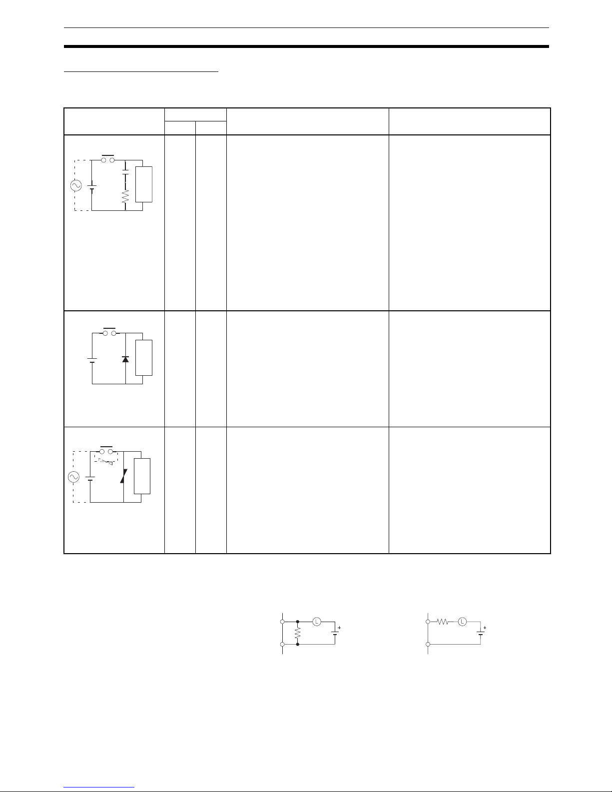
Countermeasure Examples
When switching an inductive load, connect an surge protector, diodes, etc., in
parallel with the load or contact as shown below.
When switching a load with a high inrush current such as an incandescent
lamp, suppress the inrush current as shown below.
Circuit Current Characteristic Required element
AC DC
Yes Yes If the load is a relay or solenoid, there is
a time lag between the moment the circuit is opened and the moment the load
is reset.
If the supply voltage is 24 or 48 V, insert
the surge protector in parallel with the
load. If the supply voltage is 100 to
200 V, insert the surge protector
between the contacts.
The capacitance of the capacitor must
be 1 to 0.5 µF per contact current of
1 A and resistance of the resistor must
be 0.5 to 1 Ω per contact voltage of 1 V.
These values, however, vary with the
load and the characteristics of the
relay. Decide these values from experiments, and take into consideration that
the capacitance suppresses spark discharge when the contacts are separated and the resistance limits the
current that flows into the load when
the circuit is closed again.
The dielectric strength of the capacitor
must be 200 to 300 V. If the circuit is an
AC circuit, use a capacitor with no
polarity.
No Yes The diode connected in parallel with
the load changes energy accumulated
by the coil into a current, which then
flows into the coil so that the current will
be converted into Joule heat by the
resistance of the inductive load.
This time lag, between the moment the
circuit is opened and the moment the
load is reset, caused by this method is
longer than that caused by the CR
method.
The reversed dielectric strength value
of the diode must be at least 10 times
as large as the circuit voltage value.
The forward current of the diode must
be the same as or larger than the load
current.
The reversed dielectric strength value
of the diode may be two to three times
larger than the supply voltage if the
surge protector is applied to electronic
circuits with low circuit voltages.
Yes Yes The varistor method prevents the impo-
sition of high voltage between the contacts by using the constant voltage
characteristic of the varistor. There is
time lag between the moment the circuit is opened and the moment the load
is reset.
If the supply voltage is 24 or 48 V, insert
the varistor in parallel with the load. If
the supply voltage is 100 to 200 V,
insert the varistor between the contacts.
---
CR method
Inductive
load
Power
supply
C
R
Diode method
Powe r
supply
Inductive
load
Varistor method
Power
supply
Inductive
load
OUT
COM
R
OUT
COM
R
Countermeasure 1
Providing a dark current of
approx. one-third of the rated
value through an incandescent
Countermeasure 2
Providing a limiting resistor
lamp
Page 23

Page 24

1
SECTION 1
Features and System Configuration
This section describes the features of the Temperature Control Unit and its basic system configuration.
1-1 Introduction and Features . . . . . . . . . . . . . . . . . . . . . . . . . . . . . . . . . . . . . . . . 2
1-1-1 Introduction. . . . . . . . . . . . . . . . . . . . . . . . . . . . . . . . . . . . . . . . . . . . 2
1-1-2 Features. . . . . . . . . . . . . . . . . . . . . . . . . . . . . . . . . . . . . . . . . . . . . . . 3
1-2 System Configuration . . . . . . . . . . . . . . . . . . . . . . . . . . . . . . . . . . . . . . . . . . . 6
1-2-1 Basic System Configuration . . . . . . . . . . . . . . . . . . . . . . . . . . . . . . . 6
1-2-2 Mounting the Unit. . . . . . . . . . . . . . . . . . . . . . . . . . . . . . . . . . . . . . . 6
1-3 Comparison to C200H Temperature Control Units . . . . . . . . . . . . . . . . . . . . 10
Page 25
2
Introduction and Features Section 1-1
1-1 Introduction and Features
1-1-1 Introduction
The CJ1W-TC@@@ Temperature Control Units are Special I/O Units that
receive inputs directly from thermocouple or platinum resistance thermometers, perform PID control with two degrees of freedom, and output results
through open collector outputs.
There are two main types of Unit: One provides four control loops and the
other provides two control loops with a heater burnout detection function.
Each of these has one model that is compatible with thermocouples (R, S, K,
J, T, B, or L) and another model that is compatible with platinum resistance
thermometers (JPt100 or Pt100). Both NPN outputs and PNP outputs are
available.
Autotuning of the PID control is also possible.
Available Units
Temperature Ranges
I/O type Output type
NPN outputs PNP outputs
Four control loops Thermocouple CJ1W-TC001 CJ1W-TC002
Platinum resistance thermometer CJ1W-TC101 CJ1W-TC102
Two control loops
(with heater burnout detection function)
Thermocouple CJ1W-TC003 CJ1W-TC004
Platinum resistance thermometer CJ1W-TC103 CJ1W-TC104
Item Thermocouple Platinum resistance
thermometer
K(CA) K(CA) J(IC) J(IC) T(CC) L L R S B Pt100 JPt100 ---
Input Type Setting
01234567890 12 to 9
Minimum Units 1°C0.1°C1°C0.1°C0.1°C1°C0.1°C1°C1°C1°C0.1°C0.1°C ---
1300
−200
500.0
0.0
850
−100
0.0
400.0 400.0
−200.0
−100
850
0.0
400.0
0
1700
0
1700
100
1800
−200.0
650.0
−200.0
650.0
K (CA): Chromel-alumel
J (IC): Iron-constantan
T (CC): Copper-constantan
L: Iron-constantan
R: Platinum 13% Rhodium-Platinum
S: Platinum 10% Rhodium-Platinum
B: Platinum 30% Rhodium-Platinum 6% Rhodium
Usable temperature range
(
°
C)
Settings 2 to 9 are not allowed.
1800
1600
1400
1200
1000
800
600
400
200
0
-200
Page 26

3
Introduction and Features Section 1-1
Word Allocation Data is exchanged between the CPU Unit and the Temperature Control Unit
through the PLC’s memory areas. A part of the CIO Area (the Special I/O Unit
Area) and part of the DM Area are reserved for the Special I/O Units.
The Temperature Control Unit requires 20 words in the CIO Area and 100
words in the DM Area. (The unit number set on the front of the Unit determines which words are actually allocated to the Unit.)
1-1-2 Features
Use ON/OFF Control or
PID Control with 2 or 4
Control Loops
The Temperature Control Unit can perform basic ON/OFF control as well as
PID control of two or four control loops. The PID control function has two
degrees of freedom and an autotuning function that can be used to autotune
the PID value.
Connect Temperature
Sensors Directly
Temperature sensors can be connected directly to the Temperature Control
Unit (two or four inputs). There are two models that support thermocouples
(R, S, K, J, T, B, and L thermocouples) and two models that support platinum
resistance thermometers.
500-ms Sampling Cycle PID control is performed with a sampling cycle of 500 ms, regardless of the
CPU Unit’s cycle time.
Unrestricted CPU Unit
Cycle Time
There are no restrictions on the CPU Unit’s cycle time.
RUN/STOP Control from
CPU Unit
Commands can be sent from the CPU Unit to switch the Temperature Control
Unit’s PID control between RUN and STOP.
Independent Operation in
PROGRAM Mode
A switch on the front of the Unit (pin 1 of the DIP switch) selects whether the
Temperature Control Unit will continue operation or stop when the CPU Unit is
in PROGRAM mode.
Termina l Block
Connections
Both inputs and outputs are connected through a terminal block.
Store and Display Data in
BCD or Hexadecimal
A switch on the front of the Unit (pin 3 of the DIP switch) selects whether the
Temperature Control Unit’s data is handled as 4-digit BCD or binary (i.e., 4digit hexadecimal.) This switch setting controls both the display format and the
storage format in the memory areas (CIO and DM Areas) used to exchange
data between the CPU Unit and Temperature Control Unit.
Select ON/OFF Control or
PID Control
A switch on the front of the Unit (pin 6 of the DIP switch) selects whether the
Temperature Control Unit operates with ON/OFF control or PID control with 2
degrees of freedom.
Note The setting on pin 6 sets the control method for all of the Unit’s control loops.
The factory setting is PID control.
Control Methods • ON/OFF Control
With ON/OFF control, the control output will be ON when the PV is below
the SV. The control output will be OFF when the PV is at or above the SV.
(This control method is used when the Unit is set for reverse operation.)
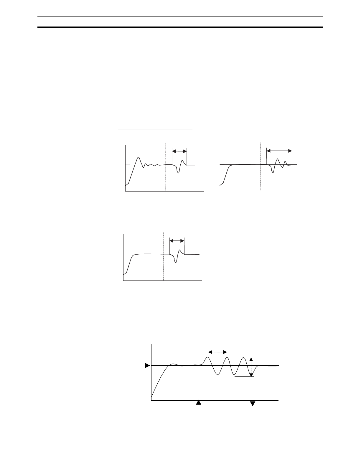
• PID Control with Two Degrees of Freedom
In earlier versions of PID control, the same controller section controlled
both the response to the SV and the response to disturbances. The weak-
Example Data storage/display format
Sensor input Binary (4-digit hexadecimal) 4-digit BCD
K: −200 to 1,300°C FF38 to FFFF to 0514
(−200 to −1 to 1,300)
F200 to 1300
(−200 to 1,300)
Page 27
4
Introduction and Features Section 1-1
ness in this design was that both responses could not be satisfied at the
same time.
1. If the disturbance response were emphasized (i.e., P and I were re-
duced and D was increased), the SV response would oscillate and
overshoot.
2. If the SV response were emphasized (i.e., P and I were increased and
D was reduced), the disturbance response would be delayed.
To overcome these problems, PID control with two degrees of freedom was
used for this Temperature Control Unit to take advantage of the strengths
of PID control and improve both disturbance and target response as shown
in 3, below.
■ Earlier PID Control Method
■ PID Control with Two Degrees of Freedom
■ Autotuning (AT) Function
The Temperature Control Unit is equipped with an autotuning (AT) function
that uses the “limit-cycle method” to calculate the optimum PID constant for
the controlled system. (The SV cannot be written for a loop if the loop is being
autotuned.)
1
2
The disturbance response is good, but
the SV response is delayed.
The SV response is good, but the
disturbance response is not.
3
Both the SV response and disturbance
response are good.
SV
AT starts.
AT stops.
Hunting period
Amplitude
Page 28

5
Introduction and Features Section 1-1
Note The “limit-cycle method” uses ON/OFF operation to cause hunting around the
SV, measures the amplitude and hunting period, and calculates the optimum
PID constants.
Control Operation
(Forward and Reverse)
The Temperature Control Unit’s control can be set to reverse operation or forward operation with pins 4 and 5 of the Unit’s DIP switch. The factory setting is
for reverse operation (heating).
One forward/reverse setting controls the operation of loops 1 and 3, and the
other forward/reverse setting controls the operation of loops 2 and 4.
With forward operation (cooling), the manipulated variable is increased as the
PV increases. With reverse operation (heating), the manipulated variable is
increased as the PV decreases.
For example, when heating control is being performed and the present temperature (PV) is lower than the target temperature (SP), the manipulated variable is increased as the difference between the PV and SP increases.
Consequently, heating control uses “reverse operation” and cooling control
uses “forward operation.”
Input Compensation
Function
This function adjusts the PV by adding an input compensation value to the
temperature measured by the sensor.
If you have an application where you want to control and display the temperature at a point that is offset from the sensor’s measurement point, use this
function to control the temperature at a value near the desired point.
Heater Burnout Detection
(Single-phase Operation
Only)
When a Two-loop Temperature Control Unit is being used, a Current Transformer (CT) can be connected to each loop to detect a heater burnout.
Two Internal Alarms for
Each Loop
There are two internal alarms per loop. Alarms can be output to the allocated
areas in the CPU Unit’s memory areas and any one of the following 9 alarm
modes can be used:
Upper and lower-limit alarm, upper-limit alarm, lower-limit alarm, upper and
lower-limit alarm with standby sequence, upper-limit alarm with standby
sequence, lower-limit alarm with standby sequence, absolute-value upperlimit alarm, and absolute-value lower-limit alarm
Store Settings in EEPROM Various Temperature Control Unit settings, such as the alarm SVs and PID
constants, can be stored in the Unit’s EEPROM using a control bit in the CPU
Unit’s allocated memory area.
Also, it is possible to set the Temperature Control Unit so that the settings
stored in EEPROM are automatically written to the appropriate area in the
CPU Unit when the power is turned ON or the Unit is restarted. This automatic
transfer function is controlled by a switch (pin 8 of the DIP switch) on the front
of the Temperature Control Unit.
0%
100%
Low
temperature
SV
High
temperature
Forward operation
0%
100%
Low
temperature
SV
High
temperature
Reverse operation
Manipulated variable
Manipulated variable
Page 29
6
System Configuration Section 1-2
Once the settings have been stored in the Temperature Control Unit and the
Unit is set for automatic transfer, the Unit will always start with those settings
whether the power has been turned OFF or not. (The settings can be changed
after startup if necessary.)
To simplify Temperature Control Unit operation, pin 8 on the DIP switch can be
turned ON to enable operation by merely turning ON the power supply and
setting Operation Data (the SP). All other settings can be used at their default
values. (Refer to 2-6-1 Settings for the default settings.)
1-2 System Configuration
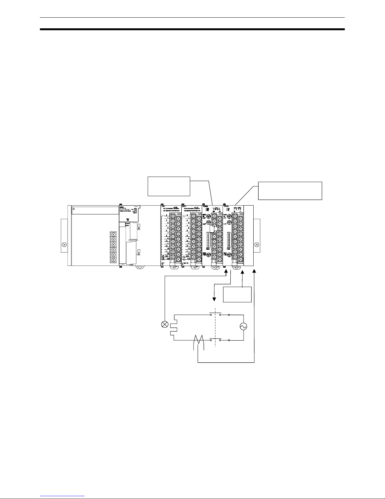
1-2-1 Basic System Configuration
The following diagram shows a basic system with a CJ1W-TC001 Temperature Control Unit (4 control loops, thermocouple inputs, and NPN outputs) and
a CJ1W-TC103 Temperature Control Unit (2 control loops with heater burnout
detection, platinum resistance thermometer inputs, and NPN outputs).
Note 1. An OMRON E54-CT1 or E54-CT3 Current Transformer must be used as
the Current Transformer (CT). Do not use any other Current Transformer.
2. Turn ON the Stop Bit for the loop to stop temperature control. If PID control
is being used and the heater is turned OFF using an operation switch input
to the heater, PID control performance will be adversely affected.
1-2-2 Mounting the Unit
The CJ1W-TC@@@ Temperature Control Units are CJ-series Special I/O
Units, so they can be mounted in a CJ-series CPU Rack or Expansion Rack.
CJ1W-TC001
Four-loop Unit,
Thermocouple,
NPN outputs
CJ1W-TC103
Two-loop Unit, platinum resistance
thermometer, NPN outputs
Power supply
for outputs
(24 VDC)
Heater
Current
Transformer
E54-CT1 or E54-CT3
Temperature Sensor
Thermocouple or platinum
resistance thermometer
Control output
200 VAC
1 kW
Page 30
7
System Configuration Section 1-2
The number of Units that can be mounted in a CPU Rack or Expansion Rack
depends on the capacity of the Rack’s Power Supply Unit and the current consumption of the other Units in the Rack.
The following table shows the maximum number of CJ1W-TC@@@ Temperature Control Units that can be mounted in a Rack if the Temperature Control
Units are the only Units being used in the Rack.
Note I/O words are allocated to the Special I/O Units based on the unique unit num-
ber set on the front of each Unit.
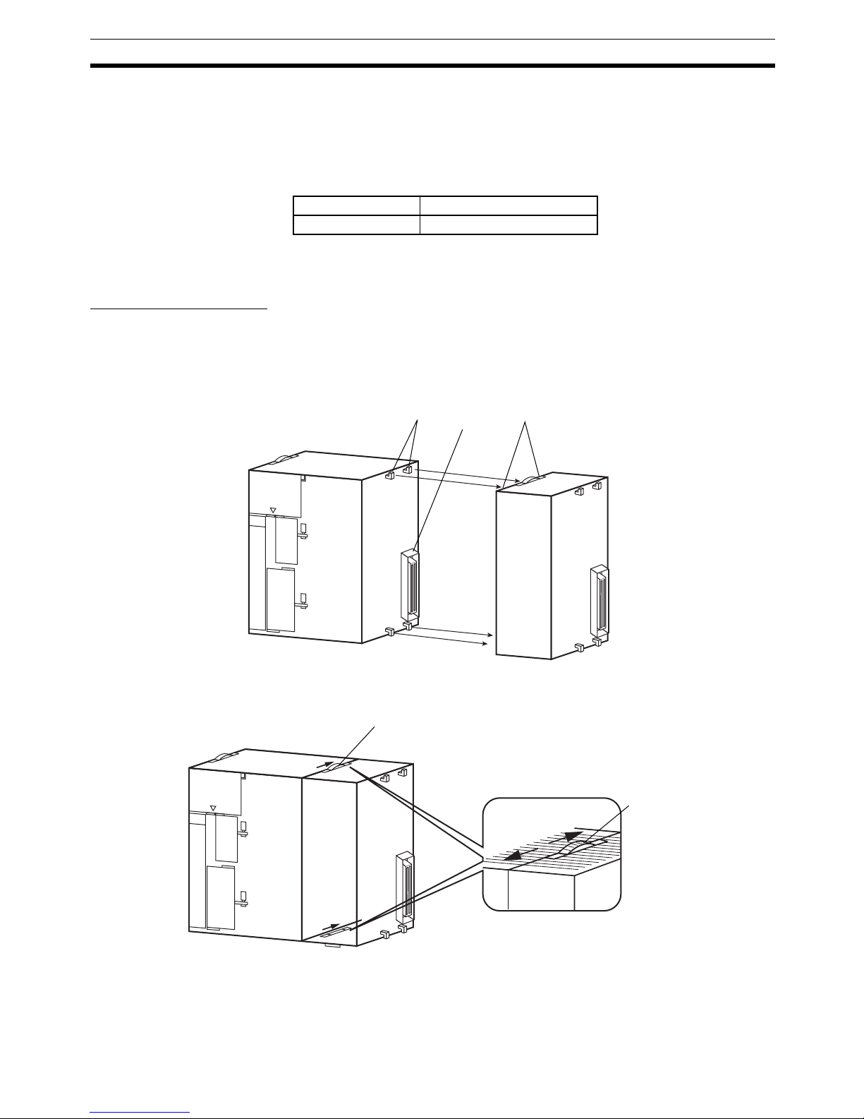
Installation Procedure Use the following procedure to install the Temperature Control Unit. The PLC
must be removed from the DIN Track in order to connect a Temperature Control Unit.
1,2,3... 1. Align the Units and connect them together so that the connectors join
smoothly and completely.
2. Slide the yellow latches on the top and bottom of the Unit until you hear the
latches click and lock the Units together.
3. Install an End Cover on the rightmost Unit.
Precautions The Unit’s functions may not be completely operational if the latches are not
locked securely.
Power Supply Unit CJ1W-TC@@@
CJ1W-PA205R 10 Units
Hooks
Connector
Openings for hooks
Slide latches back until they lock.
(The latches will click when they lock.)
Release
Lock
Sliding
latch
Page 31

8
System Configuration Section 1-2
An End Cover is provided with the CPU Unit. Always install this End Cover on
the rightmost Unit in the PLC. The CJ-series PLC will not operate properly if
the End Cover is not installed.
Handling Precautions • Always turn OFF the PLC’s power supply before connecting or discon-
necting wiring to the Unit.
• To avoid problems with noise, route the I/O wiring in a separate duct or
conduit that does not carry any high-voltage lines or power lines.
• Leave the protective label in place during wiring to prevent stray wire
strands from falling into the Unit during wiring. After wiring is completed,
remove the protective label so that air can flow through the Unit and provide proper cooling.
Precautions on
Removable Terminal
Blocks
The terminal block can be removed by pressing down on the lever at the bottom of the terminal block. Always confirm that this lever is up in the locked
position before starting operation.
TC081
M
A
C
H
N
o
.
x
1
0
1
x
1
0
0
R
U
N
E
R
C
E
R
H
A
D
J
Remove the protective label
after wiring is completed.
Page 32

9
System Configuration Section 1-2
!Caution A cold-junction compensator is attached to the terminal block for Temperature
Control Units with thermocouples. The accuracy ratings are given for the Temperature Control Unit used in a set with the cold-junction compensator. Always
use the Unit and terminal block in a set. There are labels with serial numbers
attached to the terminal blocks and Units to help keep track of the sets. When
returning a thermocouple-type Temperature Control Unit for repair, always
return the Unit and the terminal block (with the cold-junction compensator) as
a set.
B1 A1
TC001
M
A
C
H
N
o
.
×
1
0
1
×
1
0
0
R
U
N
E
R
C
E
R
H
A
D
J
Page 33

10
Comparison to C200H Temperature Control Units Section 1-3
1-3 Comparison to C200H Temperature Control Units
Item CJ-series Temperature Control Units C200H Temperature Control Units
Model number CJ1W-TC00@/10@ C200H-TC00@/10@
Unit type CJ-series Special I/O Unit C200H Special I/O Unit
Compatible PLCs CJ-series PLCs CS-series, C200HX/HG/HE, C200HS,
and C200H PLCs
Number of control loops 2 loops (with heater burnout detection)
or 4 loops
2 loops
Allocated I/O words 20 words (6 output and 14 input) 10 words (3 output and 7 input)
Control inputs Thermocouple (R, S, K, J, T, B, or L) or
platinum resistance thermometers
(JPt100 or Pt100)
Thermocouple (R, S, K, J, T, E, B, N, L,
or U) or platinum resistance thermometers (JPt100 or Pt100)
Control modes PID control or ON/OFF control
(PID control features two degrees of freedom and autotuning.)
Control outputs CJ1W-TC@01/@03:
Open collector NPN outputs (pulse),
external 24-VDC power supply
CJ1W-TC@02/@04:
Open collector PNP outputs (pulse),
external 24-VDC power supply
C200H-TC@01:
Open collector NPN outputs (pulse),
external 24-VDC power supply
C200H-TC@02:
Voltage outputs (pulse), 12-VDC outputs
C200H-TC@03:
Current outputs (linear), 4 to 20 mA DC
Setting accuracy,
indicator accuracy
Thermocouple
input
±0.3% or ±1°C (whichever is larger) ± 1
digit max.
±0.5% or ±2°C (whichever is larger) ± 1
digit max.
Platinum resistance thermometer input
±0.3% or ±0.8°C (whichever is larger)
± 1 digit max.
±0.5% or ±1°C (whichever is larger) ± 1
digit max.
Storage/display data format for data
exchanged with CPU Unit
BCD or binary (selectable) BCD only
RUN/STOP control Supported (Controlled from the CPU Unit through a bit allocated in the Special I/O
Unit area.)
Operation when CPU Unit is in PROGRAM mode
The Temperature Control Unit can be set to continue operating or stop operating
when the CPU Unit is in PROGRAM mode. (Selectable)
Auto/Manual switch for operational
output
Not supported.
Autotuning (AT) of PID constant Can be started and stopped from the
CPU Unit through bits allocated in the
Special I/O Unit area.
Can be started and stopped from the
CPU Unit through bits allocated in the I/
O Unit area or from the Data Setting
Console.
Sampling period 500 ms
Input compensation value −99.9 to 999.9 °C or °F
Data setting banks None 8 banks max.
Output wiring method Terminal block Connector
Data Setting Console Not supported (Cannot be used.) Supported (Can be used.)
Heater Burnout Detection Yes (Two-loop Units only) Yes
CT heater detection current 0.0 to 50.0 A 0.0 to 5.0 A
SV write memory EEPROM (100,000 writes) or RAM
Effect on the CPU Unit’s cycle time 0.4 ms 2.6 ms
CPU Unit’s required cycle time Unrestricted Restricted (8 ms minimum cycle time)
Dimensions 90 × 31 × 65 mm (H × W × D) 130 × 34.5 ×120.5 mm (H × W × D)
Page 34

11
SECTION 2
Specifications and Functions
This section describes the functions and specifications of the Temperature Control Unit, including technical specifications,
Unit parts, wiring, and data allocations.
2-1 Specifications . . . . . . . . . . . . . . . . . . . . . . . . . . . . . . . . . . . . . . . . . . . . . . . . . 12
2-1-1 Specifications . . . . . . . . . . . . . . . . . . . . . . . . . . . . . . . . . . . . . . . . . . 12
2-1-2 Input Function Block Diagrams . . . . . . . . . . . . . . . . . . . . . . . . . . . . 15
2-1-3 Input Specifications . . . . . . . . . . . . . . . . . . . . . . . . . . . . . . . . . . . . . 16
2-2 Application Procedure. . . . . . . . . . . . . . . . . . . . . . . . . . . . . . . . . . . . . . . . . . . 18
2-2-1 Example Operating Procedure . . . . . . . . . . . . . . . . . . . . . . . . . . . . . 19
2-3 Part Names and Functions. . . . . . . . . . . . . . . . . . . . . . . . . . . . . . . . . . . . . . . . 21
2-3-1 Part Names . . . . . . . . . . . . . . . . . . . . . . . . . . . . . . . . . . . . . . . . . . . . 21
2-3-2 Indicators . . . . . . . . . . . . . . . . . . . . . . . . . . . . . . . . . . . . . . . . . . . . . 21
2-3-3 Unit Number Switches . . . . . . . . . . . . . . . . . . . . . . . . . . . . . . . . . . . 22
2-3-4 DIP Switch Setting Functions. . . . . . . . . . . . . . . . . . . . . . . . . . . . . . 23
2-3-5 Setting the Input Type. . . . . . . . . . . . . . . . . . . . . . . . . . . . . . . . . . . . 24
2-4 Wiring . . . . . . . . . . . . . . . . . . . . . . . . . . . . . . . . . . . . . . . . . . . . . . . . . . . . . . . 25
2-4-1 Terminal Wiring Examples. . . . . . . . . . . . . . . . . . . . . . . . . . . . . . . . 25
2-4-2 Output Circuits . . . . . . . . . . . . . . . . . . . . . . . . . . . . . . . . . . . . . . . . . 26
2-4-3 I/O Wiring Examples . . . . . . . . . . . . . . . . . . . . . . . . . . . . . . . . . . . . 27
2-5 Data Exchange with the CPU Unit . . . . . . . . . . . . . . . . . . . . . . . . . . . . . . . . . 29
2-5-1 Overview. . . . . . . . . . . . . . . . . . . . . . . . . . . . . . . . . . . . . . . . . . . . . . 29
2-5-2 Data Exchange Settings . . . . . . . . . . . . . . . . . . . . . . . . . . . . . . . . . . 30
2-5-3 Memory in the Temperature Control Unit . . . . . . . . . . . . . . . . . . . . 31
2-5-4 Operation Data . . . . . . . . . . . . . . . . . . . . . . . . . . . . . . . . . . . . . . . . . 32
2-5-5 Initialization Data . . . . . . . . . . . . . . . . . . . . . . . . . . . . . . . . . . . . . . . 44
2-5-6 Operating Parameters . . . . . . . . . . . . . . . . . . . . . . . . . . . . . . . . . . . . 46
2-6 Data Ranges . . . . . . . . . . . . . . . . . . . . . . . . . . . . . . . . . . . . . . . . . . . . . . . . . . 49
2-6-1 Settings . . . . . . . . . . . . . . . . . . . . . . . . . . . . . . . . . . . . . . . . . . . . . . . 49
2-6-2 Monitored Values . . . . . . . . . . . . . . . . . . . . . . . . . . . . . . . . . . . . . . . 50
Page 35

12
Specifications Section 2-1
2-1 Specifications
2-1-1 Specifications
General
Specifications
Item Specification
Unit classification CJ-series Special I/O Unit
Compatible
Racks
CJ-series CPU Rack or CJ-series Expansion Rack
Max. number of
Units
10 Units/Rack max. (CPU Rack or Expansion Rack)
CPU Unit data
areas for data
storage/
exchange
Special I/O Unit
Area (960 words)
CIO 2000 to
CIO 2959
20 words/Unit for
constant data
exchange (6 output
words and 14 input
words)
CPU Unit to Temperature Control
Unit
• Set point (SP)
• Operating commands
•RUN/STOP control
• Start/Stop AT
• Write commands
• Heater burnout current setting
Temperature Control
Unit to CPU Unit
• Process value (PV)
• Set point (SP)
• Status
• Heater current monitor
DM words allocated
to Special I/O Units
(9,600 words)
D20000 to D29599
10 words/Unit transferred when power
is turned ON or Unit
is restarted
CPU Unit to Temperature Control
Unit
•Alarm mode
• Alarm hysteresis
90 words/Unit for
regular data
exchange
Two-way transfer
between CPU Unit
and Temperature
Control Unit
•Alarm value
• Input compensation value
• Control period
• Sensitivity
• Proportional band
• Integral time
• Derivative time
• Output monitor
Insulation resistance
20 MΩ min. (at 500 VDC) between the following points:
• Output terminals/NC terminals and external AC terminals (Power Supply Unit)
• Input terminals and external AC terminals (Power Supply Unit)
• Input terminals and output terminals
• External DC terminals (inputs, outputs, and NC) and the FG plate
• Between input terminals (sensor and CT inputs)
• Between the I/O terminals and NC terminals
Dielectric
strength
2,000 VAC 50/60 Hz for 1 min., detected current: 1 mA
• Between the output terminals/NC terminals and external AC terminals (Power Supply Unit)
1,000 VAC 50/60 Hz for 1 min., detected current: 1 mA
• Input terminals and external AC terminals (Power Supply Unit)
• Input terminals and output terminals
• External DC terminals (inputs, outputs, and NC) and the FG plate
500 VAC 50/60 Hz for 1 min., detected current: 1 mA
• Between input terminals (sensor and CT inputs)
• Between the I/O terminals and NC terminals
Internal current
consumption
250 mA max., 5 VDC
Other Other general specifications conform to the CJ-series general specifications.
Page 36

13
Specifications Section 2-1
Characteristics
Dimensions 31 × 90 × 65 mm (W × H × D)
Weight 150 g max.
Item Specification
Item Specification
Model number CJ1W-TC00@ CJ1W-TC10@
Temperature sensor Thermocouple: Types R, S, K, J, T, L, and B Platinum resistance thermometer: Types Pt100
and JPt100
Number of loops There are two types of Unit available: Four-loop Units and Two-loop Unit with heater burnout detec-
tion. (See note 1.)
Control output and
heater burnout alarm
output
NPN or PNP outputs, both with short-circuit protection (See note 1.)
Externally supplied power supply voltage: 24 VDC +10%/-15%
Maximum switching capacity: 100 mA (per output)
Leakage current: 0.3 mA max.
Residual voltage: 3 V max.
Temperature control
method
ON/OFF control or PID control with two degrees of freedom (Set with pin 6 on the Unit’s DIP
switch.)
Control operation Forward or reverse operation (Set with pins 4 and 5 on the Unit’s DIP switch.)
RUN/STOP control Supported (Controlled from the CPU Unit through bits allocated in the Special I/O Unit area.)
Operation with CPU
Unit in PROGRAM
mode
The Temperature Control Unit can be set to continue operating or stop operating when the CPU
Unit is in PROGRAM mode. (Set with pin 1 on the Unit’s DIP switch.)
Auto/Manual switch
for operational output
None
Autotuning (AT) of
PID constant
Supported (Controlled from the CPU Unit through bits allocated in the Special I/O Unit area.)
Indication accuracy Centigrade: ±0.3% PV or ±1°C (whichever is
larger) ± 1 digit max.
Farenheit: ±0.3% PV or ±2°F (whichever is
larger) ± 1 digit max.
• The accuracy will be ±2°C ± 1 digit max. when
using an L-type thermocouple or using a K or
T-type thermocouple below −100°C.
• The accuracy will be ±3°C ± 1 digit max. when
using an R or S-type thermocouple below
200°C.
• The B-type thermocouples may not be accurate below 400°C. (See note 2.)
Centigrade: ±0.3% PV or ±0.8°C (whichever is
larger) ± 1 digit max.
Farenheit: ±0.3% PV or ±1.6°F (whichever is
larger) ± 1 digit max.
Sensitivity (when
using ON/OFF control)
0.0 to 999.9 °C or °F (0.1 °C or °F units)
Proportional band 0.1 to 999.9 °C or °F (0.1 °C or °F units)
Integral (reset) time 0 to 9,999 s (one-second units)
Derivative (rate) time 0 to 9,999 s (one-second units)
Control period 1 to 99 s (one-second units)
Sampling period 500 ms (4 loops)
Output refresh
period
500 ms (4 loops)
Display refresh
period
500 ms (4 loops)
Input compensation
value
−99.9 to 999.9 °C or °F (0.1 °C or °F units)
Alarm output setting
range
−999 to 9,999 °C or °F (1 °C or °F units)
The setting range will be −99.9 to 999.9 °C or °F (0.1 °C or °F units) when using a platinum resistance thermometer or using a K or J-type thermocouple in decimal-point mode.
Page 37

14
Specifications Section 2-1
Note 1. The last three digits of the model number indicate the Unit’s features:
2. Indication accuracy of thermocouples
• Accuracy ratings are given for the Temperature Control Unit used in a
set with a cold-junction compensator (on the terminal block). Always
use the Unit and terminal block in a set. There are labels with serial
numbers attached to the terminal blocks and Units to help keep track
of the sets.
• When returning a thermocouple-type Temperature Control Unit for repair, always return the Unit and the terminal block (with the cold-junction compensator) as a set.
Heater Burnout (HB)
Alarm
Note If the control output is ON for less than 200 ms, the heater burnout detection
function will not operate and heater current measurement will not be performed.
Current Transformer
(CT) Ratings
External terminal
connections
Removable terminal block with 18 points (M3 screws)
Effect on the CPU
Unit’s cycle time
0.4 ms
Item Specification
CJ1W-TC @ 0 @
Output type
Always 0.
Input type
0: Thermocouple input
1: Platinum resistance thermometer input
1: NPN outputs, four-loop control outputs
2: PNP outputs, four-loop control outputs
3: NPN outputs, two-loop control outputs and heater
burnout alarm outputs
4: PNP outputs, two-loop control outputs and heater
burnout alarm outputs
Item Specification
Maximum heater current Single-phase AC, 50 A
Indication accuracy of input current
±5% of full scale ± 1 digit max.
Heater burnout alarm setting
range
0.1 to 49.9 A (0.1 A units)
The heater burnout detection function will not
operate if the set value is set to 0.0 A or 50.0 A.
(When the SV is 0.0 A, the heather burnout alarm
will be OFF. When the SV is 50.0 A, the heater
burnout alarm will be ON.)
Min. detectable ON time
(See note.)
200 ms
Item E54-CT1 E54-CT3
Max. continuous heater current 50 A 120 A (See note 1.)
Dielectric strength 1,000 VAC (1 min.)
Vibration resistance
50 Hz, 98 m/s
2
Weight Approx. 11.5 g Approx. 50 g
Accessories None Contacts (2)
Plugs (2)
Page 38

15
Specifications Section 2-1
Note 1. The maximum continuous heater current that can be detected at a CJ1W-
TC@@@ Temperature Control Unit is 50 A.
2. Do not use any Current Transformer (CT) other than the OMRON E54-CT1
or E54-CT3 Current Transformer.
2-1-2 Input Function Block Diagrams
Four-loop Units
Two-loop Units with
Heater Burnout Alarm
CPU Unit
Special I/O
Unit Area
BCD
Binary
°C
°F
Alarm 1
Alarm 2
ON/OFF control
PID control
Forward/
reverse
switching
Controller
Temperature Control Unit
Loop 1
Temperature
input
Control
output
Loop 2
Loop 3
Loop 4
Same as 1.
Same as 1.
Same as 1.
Input 1
Control
output 1
Input 2
Control
output 2
Input 3
Control
output 3
Input 4
Control
output 4
CT input
Loop 2
Same as 1.
Heater
burnout
alarm
CT
input 1
Heater
burnout
alarm
output 1
Input 2
Control
output 1
CT input 2
HB alarm
output 2
CPU Unit
Special I/O
Unit Area
BCD
Binary
°C
°F
Alarm 1
Alarm 2
ON/OFF control
PID control
Forward/
reverse
switching
Controller
Temperature Control Unit
Loop 1
Temperature
input
Control
output
Input 1
Control
output 1
Page 39

16
Specifications Section 2-1
2-1-3 Input Specifications
A switch on the front of the Unit (pin 3 of the DIP switch) selects whether the
Temperature Control Unit’s data is stored and indicated as 4-digit BCD or
binary (i.e., 4-digit hexadecimal). Pin 2 of the DIP switch selects whether the
temperature is indicated in
°C or °F.
The indicated range will be within ±20°C or ±20°F of the setting ranges shown
in the following table. (See note 1.)
Thermocouple Input
Setting Ranges
Platinum Resistance
Thermometer Input
Setting Ranges
Note 1. If the allowed indication range is exceeded, a sensor error will occur, the
corresponding Sensor Error Flag will be turned ON, and the PV will contain
the data “CCCC.” When a sensor error occurs, that control loop’s control
output will be turned OFF. The alarm function will operate because the PV
indicates an abnormally high temperature.
No. Thermocouple type Range in °C Range in °F
Binary (4-digit Hex) 4-digit BCD Binary (4-digit Hex) 4-digit BCD
0K: −200 to 1,300°C
(−300 to 2,300°F)
FF38 to FFFF to 0514
(−200 to −1 to 1,300)
F200 to 1300
(−200 to 1,300)
FED4 to FFFF to 08FC
(−300 to −1 to 2,300)
F300 to 2300
(−300 to 2,300)
1 K: 0.0 to 500°C
(0.0 to 900.0°F)
0000 to 1388
(0.0 to 500.0)
0000 to 5000
(0.0 to 500.0)
0000 to 2328
(0.0 to 900.0)
0000 to 9000
(0.0 to 900.0)
2J: −100 to 850°C
(−100 to 1,500°F)
FF9C to FFFF to 0352
(−100 to −1 to 850)
F100 to 0850
(−100 to 850)
FF9C to FFFF to 05DC
(−100 to −1 to 1,500)
F100 to 1500
(−100 to 1,500)
3 J: 0.0 to 400°C
(0.0 to 750.0°F)
0000 to 0FA0
(0.0 to 400.0)
0000 to 4000
(0.0 to 400.0)
0000 to 1D4C
(0.0 to 750.0)
0000 to 7500
(0.0 to 750.0)
4T: −200.0 to 400.0°C
(−300.0 to 700.0°F)
F830 to FFFF to 0FA0
(−200.0 to −0.1 to 400.0)
F999 to 4000
(−99.9 to 400.0)
See note 3.
F448 to FFFF to 1B58
(−300.0 to −0.1 to 700.0)
F999 to 7000
(−99.9 to 700.0)
See note 3.
5L: −100 to 850°C
(−100 to 1,500°F)
FF9C to FFFF to 0352
(−100 to −1 to 850)
F100 to 0850
(−100 to 850)
FF9C to FFFF to 05DC
(−100 to −1 to 1,500)
F100 to 1500
(−100 to 1,500)
6 L: 0.0 to 40 °C
(0.0 to 750.0°F)
0000 to 0FA0
(0.0 to 400.0)
0000 to 4000
(0.0 to 400.0)
0000 to 1D4C
(0.0 to 750.0)
0000 to 7500
(0.0 to 750.0)
7 R: 0 to 1,700°C
(0 to 3,000 °F)
0000 to 06A4
(0 to 1,700)
0000 to 1700
(0.0 to 1,700)
0000 to 0BB8
(0 to 3,000)
0000 to 3000
(0.0 to 3,000)
8 S: 0 to 1,700°C
(0 to 3,000 °F)
0000 to 06A4
(0 to 1,700)
0000 to 1700
(0.0 to 1,700)
0000 to 0BB8
(0 to 3,000)
0000 to 3000
(0.0 to 3,000)
9 B: 100 to 1,800°C
(300 to 3,200 °F)
See note 2.
0064 to 0708
(100 to 1,800)
0100 to 1800
(100 to 1,800)
012C to 0C80
(300 to 3,200)
0300 to 3200
(300 to 3,200)
No. Thermocouple type Range in °C Range in °F
Binary (4-digit Hex) 4-digit BCD Binary (4-digit Hex) 4-digit BCD
0Pt100:
−200.0 to 650.0°C
(−300.0 to 1,200.0 °F)
F830 to FFFF to 1964
(−200.0 to −0.1 to 650.0)
F999 to 6500
(−99.9 to 650.0)
See note 3.
F448 to FFFF to 2EE0
(−300.0 to −0.1 to
1,200.0)
F999 to 9999
(−99.9 to 999.9)
See note 3.
1 JPt100:
−200.0 to 650.0°C
(−300.0 to 1,200.0 °F)
F830 to FFFF to 1964
(−200.0 to −0.1 to 650.0)
F999 to 6500
(−99.9 to 650.0)
See note 3.
F448 to FFFF to 2EE0
(−300.0 to −0.1 to
1,200.0)
F999 to 9999
(−99.9 to 999.9)
See note 3.
2 to 9--- Settings 2 through 9 are not allowed. Settings 2 through 9 are not allowed.
Page 40

17
Specifications Section 2-1
2. The lower-limit indication for B-type thermocouples is 0°C or 0°F.
3. When the data format is BCD, the indicated temperature will remain fixed
at the lower limit value or upper limit value when the temperature exceeds
the allowed indication range but does not exceed the setting range.
When the display units are 0.1
°C or 0.1°F, the display’s lower limit value is
−99.9 and the upper limit value is 999.9.
4. When the input type setting switch has been changed, the SV and input
compensation values will change as follows:
• If the SV exceeds the setting range, it will be fixed at the lower limit or
upper limit of the setting range.
• The position of the decimal point will change if necessary.
For example, when the temperature range is changed by changing the input type setting switch from 0 (K-type thermocouple with a temperature
range of
−200 to 1,300°C) to 1 (K-type thermocouple with a temperature
range of 0.0 to 500.0
°C), an SV of 200°C would be changed to 20.0°C.
Page 41

18
Application Procedure Section 2-2
2-2 Application Procedure
The procedure for installing and setting up the Temperature Control Unit is
illustrated below.
Set unit number.
Set the input type.
Set the functions of the
Temperature Control Unit.
Wire the Unit.
Turn ON the power
supply to the PLC.
Create I/O tables.
Make initial settings in the words
allocated to the Unit in the Special I/O
Unit Area inside the DM Area.
Cycle the power supply to
the PLC.
Program the operation for the
Unit in the ladder program.
• Set the unit number on the front panel of the Temperature Control Unit.
• Set the Input Type Switch on the front panel of the Temperature Control Unit.
• Set the function switches on the front panel of the Temperature Control Unit.
Forward/reverse operation
Control method: ON/OFF control or PID control
°C or °F selection
Data format: BCD or 16-bit binary
• Switch settings on the front panel are read only when the
power supply is turned ON.
• Set the alarm mode and alarm hysteresis.
• Or turn the Special I/O Unit Restart Bit ON and then back
OFF again.
• The initialization settings in the words allocated in the
DM Area are read only then the power supply is turned
ON or the Unit is reset.
• Use the MOV (021) or XFER(070) instruction to read and
write process values and set points, as well as Operating
Parameters (control cycles or PID constants) or Operation Data (RUN/STOP control or starting/stopping autotuning).
Page 42

19
Application Procedure Section 2-2
2-2-1 Example Operating Procedure
The following settings are used in this example for a Four-loop Temperature
Control Unit.
Input type: Thermocouple
Input: K thermocouple (0.0 to 500.0
°C)
Data format: BCD
The operating procedure through reading the process value for each loop is
given in this section.
Settings
1,2,3... 1. Set the Unit number referring to 2-3-3 Unit Number Switches.
If the unit number is set to 1, CIO 2010 to CIO 2029 and D20100 to D20199
will be allocated to the Unit as a Special I/O Unit.
2. Set the input type referring to 2-3-5 Setting the Input Type. Set the switch
on the front panel of the Unit to 1 for a K thermocouple (0.0 to 500.0
°C).
3. Set the Unit’s functions referring to 2-3-4 DIP Switch Setting Functions. Be
sure that pin 2 is OFF to select centigrade and that pin 3 is OFF to select
BCD.
D00100
D00101
D00102
D00103
Loop 1
Loop 2
Loop 3
Loop 4
K thermocouple
(0.0 to 500.0
°C)
CJ1W-TC001
Unit number: 1
CPU Unit
Ladder program
12345678
MODE
Page 43

20
Application Procedure Section 2-2
4. Mount and wire the Unit, referring to 1-2-2 Mounting the Unit.
5. Turn ON the power supply to the PLC.
Creating I/O Tables There two different methods that can be used to create I/O tables with the CJ-
series PLCs. Refer to the CJ Series Programmable Controllers Operation
Manual (W393) for details.
Automation Creation The PLC can be set to automatically create I/O tables at startup. If this is
done, the user does not need to create the I/O tables.
Use-set I/O Tables After turning ON the PLC, create the I/O tables. The key sequence for creating
I/O tables from a Programming Console is shown below.
Program In this example, the process value (PV) output to the words allocated in the
CIO Area to the Temperature Control Unit as a Special I/O Unit are stored in
memory for four loops. The words n+3, n+4, n+13, and n+14 will contain the
PV and are CIO 2013, CIO 2014, CIO 2023, and CIO 2024 in this example.
Note 1. Determined by the unit number that is set for the Temperature Control Unit
as a Special I/O Unit. (Refer to 2-3-3 Unit Number Switches.)
2. Set as desired in programming.
3. Sensor Error Flags are allocated to bit 14 of n+8, n+9, n+18, and n+19.
(Refer to Four-loop Units on page 33.)
Clear
FUN Shift CH/*DM
CHG
9713
Write
0
or
1
Clear
Input type Loop PV address (n = CIO
2010) (See note 1.)
Storage addresses
(See note 2.)
K thermocouple
(0.0 to 500.0 °C)
1 n+3 = CIO 2013 D00100
2 n+4 = CIO 2014 D00101
3 n+13 = CIO 2023 D00102
4 n+14 = CIO 2024 D00103
Page 44

21
Part Names and Functions Section 2-3
2-3 Part Names and Functions
2-3-1 Part Names
2-3-2 Indicators
Status Indicators The Status Indicators indicate the operating status of the Temperature Control
Unit, as explained in the following table.
MOV(21)
2013
D00100
MOV(21)
2014
D00101
MOV(21)
2023
D00102
MOV(21)
2024
D00103
CIO 201814
Sensor Error Flag for Loop 1
CIO 201914
Sensor Error Flag for Loop 2
CIO 202814
Sensor Error Flag for Loop 3
CIO 202914
Sensor Error Flag for Loop 4
0
0
9
9
8
8
7
7
6
6
5
5
4
4
3
3
2
2
1
1
0
0
9
9
8
8
7
7
6
6
5
5
4
4
3
3
2
2
1
1
0
0
9
9
8
8
7
7
6
6
5
5
4
4
3
3
2
2
1
1
Connector
DIN Track
Mounting Pin
Sliding Latch
Terminal Block
Lock LeverSliding Latch
Input Type
Switch
DIP Switch
Unit Number
Switches
Status
Indicators
Output Indicators
Terminal
Block
Indicator Name Color Status Meaning
RUN RUN Indicator Green Lit Normal operating status
Not lit Temperature control is stopped.
ERC Temperature Control
Unit Error
Red Lit An error occurred in the Temperature Control Unit itself,
such as a Sensor Error or Initialization Error.
Not lit Normal operating status
Page 45

22
Part Names and Functions Section 2-3
Output Indicators The Output Indicators light to indicate when the corresponding Temperature
Control Unit output is ON.
2-3-3 Unit Number Switches
The CPU Unit and the Temperature Control Unit exchange data through the
parts of the CPU Unit’s CIO and DM Areas that are reserved for Special I/O
Units. The Temperature Control Unit’s unit setting determines which words
are allocated.
The Temperature Control Unit occupies 20 words in the Special I/O Unit Area,
so do not set the same unit number or the next unit number on another Special I/O Unit. Since the Temperature Control Unit occupies the words for two
unit numbers, the maximum unit number allowed is 94 (unlike most other Special I/O Units that can be set to unit number 95.)
Note If two or more Special I/O Units are assigned the same unit number, a “UNIT
No. DPL ERR” error (in the Programming Console) will be generated (A40113
will turn ON) and the PLC will not operate.
ERH CPU Unit Error Red Lit An error occurred in the CPU Unit.
Not lit Normal operating status
Indicator Name Color Status Meaning
Switch
setting
Unit
number
Words allocated in Special I/O
Unit Area in CIO Area
Words allocated in Special I/O
Unit Area in DM Area
0 0 CIO 2000 to CIO 2019 D20000 to D20099
1 1 CIO 2010 to CIO 2029 D20100 to D20199
2 2 CIO 2020 to CIO 2039 D20200 to D20299
3 3 CIO 2030 to CIO 2049 D20300 to D20399
4 4 CIO 2040 to CIO 2059 D20400 to D20499
5 5 CIO 2050 to CIO 2069 D20500 to D20599
6 6 CIO 2060 to CIO 2079 D20600 to D20699
7 7 CIO 2070 to CIO 2089 D20700 to D20799
8 8 CIO 2080 to CIO 2099 D20800 to D20899
9 9 CIO 2090 to CIO 2109 D20900 to D20999
: : : :
n n CIO 2000 + (n x 10) to
CIO 2000 + (n x 10) + 19
D20000 + (n x 100) to
D20000 + (n x 100) + 99
: : : :
94 94 CIO 2940 to CIO 2959 D29400 to D29499
Page 46

23
Part Names and Functions Section 2-3
2-3-4 DIP Switch Setting Functions
ON is to the right.
Operation in PROGRAM
mode (Pin 1)
The following table shows how the Temperature Control Unit will operate
when the CPU Unit’s operating mode is changed.
Temperature Units (Pin 2) Select either
°C display (centigrade) or °F display (farenheit). When °F is
selected, the temperature is converted using the following equation:
°F = (°C × 1.8) + 32
Data Format (Pin 3) Pin 3 selects whether the data exchanged between the Temperature Control
Unit and CPU Unit is handled as 4-digit BCD or binary (i.e., 4-digit hexadecimal.) This switch setting controls the data format for the various settings such
as SPs, PVs, alarm settings in both the CIO and DM Areas.
Note If BCD format is selected, it isn’t necessary to convert the data (Binary to BCD
conversion) in the program when displaying the actual temperature so the ladder program load can be reduced. However, parts of some temperature
ranges cannot be displayed in BCD so it will be necessary to use the binary
format in those cases.
Pin Function ON OFF Factory
setting
1 Operation when CPU Unit is in
PROGRAM mode
Continue Stop OFF
2 Temperature units (°C/°F) °F °C
3 Data format 16-bit binary 4-digit BCD
4 Control operation (loops 1 and 3) Forward
(cooling)
Reverse
(heating)
5 Control operation (loops 2 and 4) Forward
(cooling)
Reverse
(heating)
6 Control method ON/OFF control PID control
7 Initialize settings in EEPROM Initialize Do not initialize
8 Transfer settings in EEPROM Transfer Do not transfer ON
12345678
MODE
Temperature Control Unit
settings
Operation of Temperature Control Unit when CPU
Unit’s operating mode is changed
Pin 1 Stop Bit From RUN or MONITOR
to PROGRAM
From PROGRAM
to RUN or MONITOR
OFF (Stop) Run Stop operation Continue operation
Stop Stop operation Stop operation
ON (Continue) Run Continue operation Continue operation
Stop Stop operation Stop operation
Pin 3 setting Data format Example
(SP: −200 to 1,300°C)
ON Binary (4-digit Hexadecimal) FF38 to FFFF to 0514
(−200 to −1 to 1,300)
OFF 4-digit BCD F200 to 1300
(−200 to 1,300)
Page 47

24
Part Names and Functions Section 2-3
Control Operation for
Loops 1 and 3 (Pin 4)
Pin 4 selects forward (cooling) operation (ON) or reverse (heating) operation
(OFF) for control loops 1 and 3.
Control Operation for
Loops 2 and 4 (Pin 5)
Pin 5 selects either forward (cooling) operation (ON) or reverse (heating)
operation (OFF) for control loops 2 and 4.
Control Method (Pin 6) Pin 6 selects either ON/OFF control (ON) or PID control (OFF).
• If ON/OFF control is being used, the width of the hysteresis loop (hysteresis) can be set to adjust the control sensitivity.
• If PID control (PID control with two degrees of freedom) is being used,
the PID constants can be set automatically with the autotuning function.
Initialize EEPROM
Settings (Pin 7)
If pin 7 is ON, the settings in EEPROM will be initialized to their factory
defaults when the Temperature Control Unit is turned ON or restarted. (Initialize EEPROM only when a Hardware Check Error has occurred. Refer to 5-1-3
Alarms Detected by the Temperature Control Unit for details.)
Transfer EEPROM
Settings (Pin 8)
If pin 8 is ON, the settings in the Temperature Control Unit’s EEPROM will be
transferred to the corresponding words in the CPU Unit’s DM Area when the
Temperature Control Unit is turned ON or restarted. Turn ON pin 8 if you want
the Temperature Control Unit to operate with settings stored in EEPROM.
The settings in the Temperature Control Unit’s RAM can be saved to
EEPROM by turning ON the corresponding loop’s Save Bit. Refer to 2-5-3
Memory in the Temperature Control Unit for details on the settings.
2-3-5 Setting the Input Type
Thermocouple
Temperature Control Units
Platinum Resistance
Thermometer
Temperature Control Units
Input type
setting
Typ e Temp erat ure ranges
Centigrade Farenheit
0K−200 to 1,300°C −300 to 2,300°F
1 K 0.0 to 500.0°C 0.0 to 900.0°F
2J−100 to 850°C −100 to 1,500°F
3 J 0.0 to 400.0°C 0.0 to 750.0°F
4T−200.0 to 400.0°C −300.0 to 700.0°F
5L−100 to 850°C −100 to 1,500°F
6 L 0.0 to 400.0 °C 0.0 to 750.0°F
7 R 0 to 1,700°C 0 to 3,000 °F
8 S 0 to 1,700°C 0 to 3,000 °F
9 B 100 to 1,800°C 300 to 3,200 °F
Input type
setting
Typ e Temp erat ure ranges
Centigrade Farenheit
0Pt100−200.0 to 650.0°C −300.0 to 1,200.0°F
1JPt100−200.0 to 650.0°C −300.0 to 1,200.0°F
2 to 9 Do not set 2 through 9.
Page 48

25
Wiring Section 2-4
2-4 Wiring
2-4-1 Terminal Wiring Examples
Thermocouple
Temperature Control
Units
Note Do not connect any wiring to the N.C. terminals.
Platinum Resistance
Thermometer
Temperature Control
Units
Note Do not connect any wiring to the N.C. terminals.
CJ1W-TC001
(4 loops, NPN outputs)
CJ1W-TC002
(4 loops, PNP outputs)
CJ1W-TC003
(2 loops, NPN outputs, HB alarm)
CJ1W-TC004
(2 loops, PNP outputs, HB alarm)
Input 2 −
Input 2 +
Cold-junction comp.
Cold-junction comp.
Input 1 −
Input 1 +
N.C.
N.C.
Input 3
−
Input 3 +
Output 1
Output 3
24 V
B1
B2
B3
B4
B5
B6
B7
B8
B9
Input 4 −
Input 4 +
Output 2
Output 4
0 V COM (
−)
A1
A2
A3
A4
A5
A6
A7
A8
A9
Input 2 −
Input 2 +
Cold-junction comp.
Cold-junction comp.
Input 1 −
Input 1 +
N.C.
N.C.
Input 3
−
Input 3 +
Output 1
Output 3
24 V COM (
+)
B1
B2
B3
B4
B5
B6
B7
B8
B9
Input 4 −
Input 4 +
Output 2
Output 4
0 V
A1
A2
A3
A4
A5
A6
A7
A8
A9
Input 2 −
Input 2 +
Cold-junction comp.
Cold-junction comp.
Input 1 −
Input 1 +
N.C.
N.C.
CT input 1
CT input 1
Output 1
HB output 1
24 V
B1
B2
B3
B4
B5
B6
B7
B8
B9
CT input 2
CT input 2
Output 2
HB output 2
0 V COM (
−)
A1
A2
A3
A4
A5
A6
A7
A8
A9
Input 2 −
Input 2 +
Cold-junction comp.
Cold-junction comp.
Input 1 −
Input 1 +
N.C.
N.C.
CT input 1
CT input 1
Output 1
HB output 1
24 V COM (
+)
B1
B2
B3
B4
B5
B6
B7
B8
B9
CT input 2
CT input 2
Output 2
HB output 2
0 V
A1
A2
A3
A4
A5
A6
A7
A8
A9
CJ1W-TC101
(4 loops, NPN outputs)
CJ1W-TC102
(4 loops, PNP outputs)
CJ1W-TC103
(2 loops, NPN outputs, HB alarm)
CJ1W-TC104
(2 loops, PNP outputs, HB alarm)
Input 2 B’
Input 2 B
Input 2 A
Input 4 B’
Input 4 B
Input 4 A
Output 2
Output 4
0 V COM (
−)
Input 1 B’
Input 1 B
Input 1 A
Input 3 B’
Input 3 B
Input 3 A
Output 1
Output 3
24 V
B1
B2
B3
B4
B5
B6
B7
B8
B9
A1
A2
A3
A4
A5
A6
A7
A8
A9
Input 2 B’
Input 2 B
Input 2 A
Input 4 B’
Input 4 B
Input 4 A
Output 2
Output 4
0 V COM (
−)
Input 1 B’
Input 1 B
Input 1 A
Input 3 B’
Input 3 B
Input 3 A
Output 1
Output 3
24 V COM (
+)
B1
B2
B3
B4
B5
B6
B7
B8
B9
A1
A2
A3
A4
A5
A6
A7
A8
A9
Input 2 B’
Input 2 B
Input 2 A
N.C.
CT input 2
CT input 2
Output 2
HB output 2
0 V COM (
−)
Input 1 B’
Input 1 B
Input 1 A
N.C.
CT input 1
CT input 1
Output 1
HB output 1
24 V
B1
B2
B3
B4
B5
B6
B7
B8
B9
A1
A2
A3
A4
A5
A6
A7
A8
A9
Input 2 B’
Input 2 B
Input 2 A
N.C.
CT input 2
CT input 2
Output 2
HB output 2
0 V
Input 1 B’
Input 1 B
Input 1 A
N.C.
CT input 1
CT input 1
Output 1
HB output 1
24 V COM (
+)
B1
B2
B3
B4
B5
B6
B7
B8
B9
A1
A2
A3
A4
A5
A6
A7
A8
A9
Page 49

26
Wiring Section 2-4
2-4-2 Output Circuits
The following diagrams show the internal output circuits.
Output Circuits
NPN Outputs
(CJ1W-TC@01 and
CJ1W-TC@03)
NPN Outputs
(CJ1W-TC@02 and
CJ1W-TC@04)
24 V
COM
Output Indicator
Internal circuits
COM
0 V
Output Indicator
Internal circuits
Page 50

27
Wiring Section 2-4
2-4-3 I/O Wiring Examples
Thermocouple
Temperature Control Units
• Do not touch or remove the cold-junction compensator.
• Use the type of sensor selected on the Input Type Switch.
• The Temperature Control Unit and Terminal Block are a matched set, so
use the Temperature Control Unit and Terminal Block with matching serial
numbers.
• Do not connect anything to the N.C. terminals. (The N.C. terminals cannot
even be used as junction terminals.)
• Do not connect any Current Transformer to the CT input terminals other
than an OMRON E54-CT1 or E54-CT3.
CJ1W-TC004
CJ1W-TC003
CJ1W-TC002
CJ1W-TC001
CJ1W-TC001
(4 loops, NPN outputs)
CJ1W-TC002
(4 loops, PNP outputs)
CJ1W-TC003
(2 loops, HB alarm, NPN
outputs)
CJ1W-TC004
(2 loops, HB alarm, PNP
outputs)
Loop 4
Coldjunction
Loop 3
Loop 2
Loop 1
Loop 4
Coldjunction
Loop 3
Loop 2
Loop 1
Coldjunction
Loop 2
Loop 1
Coldjunction
Loop 2
Loop 1
Page 51

28
Wiring Section 2-4
Platinum Resistance
Thermometer
Temperature Control Units
Note 1. Use the type of sensor selected on the Input Type Switch.
2. Do not connect anything to the N.C. terminals. (The N.C. terminals cannot
even be used as junction terminals.)
3. Do not connect any Current Transformer to the CT input terminals other
than an OMRON E54-CT1 or E54-CT3.
4. Always attach crimp terminals to the wiring that connects to the terminal
block and tighten the terminal screws securely. The terminal screws are
M3 screws and need to be tightened to a torque of 0.5 N
⋅m.
5. Use wire that is AWG 22 to AWG 18.
6. Observe the following precautions when wiring to minimize noise and optimize the Temperature Control Unit’s operation.
• Use twisted-pair shielded wire for the output wiring.
• Keep the I/O lines away from power lines including AC power supply
lines and high-power lines. Do not run the I/O lines in the same duct or
conduit as power lines.
CJ1W-TC101
CJ1W-TC102
CJ1W-TC103
CJ1W-TC104
Loop 2
CJ1W-TC101
(4 loops, NPN outputs)
CJ1W-TC102
(4 loops, PNP outputs)
CJ1W-TC103
(2 loops, HB alarm, NPN
outputs)
CJ1W-TC104
(2 loops, HB alarm, PNP
outputs)
Loop 4
Loop 1Loop 3
Loop 2Loop 4
Loop 1Loop 3
Loop 2
Loop 1
Loop 2
Loop 1
M3
Fork terminal
Round terminal
6.0 mm max.
6.0 mm max.
Page 52

29
Data Exchange with the CPU Unit Section 2-5
• Noise from the power supply line may be superimposed on I/O signals
if equipment that generates high frequency noise is used nearby or the
Temperature Control Unit’s power line is shared with electrical welding
equipment or discharging equipment. In this case, install a noise filter
at the power supply inputs.
2-5 Data Exchange with the CPU Unit
2-5-1 Overview
The Temperature Control Unit exchanges the following data with the CPU
Unit.
• Operation Data
• Initialization Data
• Operating Parameters
Data exchange between the CPU Unit and the Temperature Control Unit is
performed through the words allocated to the Temperature Control Unit as a
Special I/O Unit in the CIO and DM Areas of the CPU Unit. The Operation
Data is in the Special I/O Unit Area in the CIO Area and the Initialization Data
and Operating Parameters are in the Special I/O Unit Area in the DM Area.
As shown in the above diagram, Special I/O Unit Areas are allocated for the
three types of data in the CIO and DM Areas according to the unit number set
for the Temperature Control Unit as a Special I/O Unit.
Operation Data The basic data used to operate the Temperature Control Unit is exchanged
with the CPU Unit as Operation Data during the CPU Unit’s I/O refresh period.
Operation Data includes the Process Values, Set Points, Stop Bits, Start AT
Bits, Stop AT Bits, and other data.
Initialization Data The data used to initialize the Temperature Control Unit is exchanged with the
CPU Unit as Initialization Data when the PC is turned ON or the Temperature
Control Unit is restarted. Initialization Data includes the Alarm Modes, Alarm
Hysteresis, and other data.
Operating Parameters The parameters that control Temperature Control Unit operation are
exchanged with the CPU Unit as Operating Parameters during the CPU Unit’s
I/O refresh period. Operating Parameters include the Alarm SVs, Control
Cycles, Proportional Bands, Integral Times, and other parameters.
20 words
100
words
10
words
90
words
n = 2000 + unit No. x 10
n + 19 =
2000 + unit No. x 10 + 19
m = D20000 + unit No. x 100
m + 9 =
D20000 + unit No. x 100 +9
m + 10 =
D20000 + unit No. x 100 + 10
m + 99 =
D20000 + unit No. x 100 + 99
CIO Area
Loop 1 PV
Loop 2 PV
DM Area
Alarm Mode
Etc.
Alarm 1 SV
Etc.
I/O refresh
Power ON and
restart
I/O refresh
Temperature Control Unit
Operation Data
Continuously
exchanges basic
data with CPU Unit
Exchanges the alarm
mode, alarm hysteresis,
etc.
Continuously
exchanges operating
parameters.
CJ-series CPU Unit
Etc.
Initialization Data
Operating Parameters
Page 53

30
Data Exchange with the CPU Unit Section 2-5
2-5-2 Data Exchange Settings
Data Format The format used to store data during data exchange between the CPU Unit
and Temperature Control Unit in the words allocated to the Temperature Control Unit in the CIO and DM Areas must be set in advance. The data format is
set using pin 3 on the DIP switch for function settings. It can be set to either 4digit BCD or 16-bit binary (4-digit hexadecimal). The same format is used for
user-set and system-set data and for the Special I/O Areas in both the CIO
and DM Area.
Unit Number The words allocated to the Temperature Control Unit in the CIO and DM
Areas are determined by the unit number set for the Temperature Control Unit
as a Special I/O Unit.
Note 1. If two or more Special I/O Units are assigned the same unit number, an
“UNIT No. DPL ERR” error (in the Programming Console) will be generated (A40113 will turn ON) and the PLC will not operate.
2. Each Temperature Control Unit is allocated the words for two unit numbers.
Do not use assign the unit number after one assigned to a Temperature
Control Unit to any other Unit. For example, if unit number 5 is allocated to
a Temperature Control Unit, the words for both unit number 5 and 6 will be
allocated to it, and unit number 6 must not be assigned to any other Unit.
Pin 3 Data storage format
ON 16-bit binary
OFF (default) 4-digit BCD
Switch
setting
Unit
number
Words allocated in Special I/O
Unit Area in CIO Area
Words allocated in Special I/O
Unit Area in DM Area
0 0 CIO 2000 to CIO 2019 D20000 to D20099
1 1 CIO 2010 to CIO 2029 D20100 to D20199
2 2 CIO 2020 to CIO 2039 D20200 to D20299
3 3 CIO 2030 to CIO 2049 D20300 to D20399
4 4 CIO 2040 to CIO 2059 D20400 to D20499
5 5 CIO 2050 to CIO 2069 D20500 to D20599
6 6 CIO 2060 to CIO 2079 D20600 to D20699
7 7 CIO 2070 to CIO 2089 D20700 to D20799
8 8 CIO 2080 to CIO 2099 D20800 to D20899
9 9 CIO 2090 to CIO 2109 D20900 to D20999
: : : :
n n CIO 2000 + (n x 10) to
CIO 2000 + (n x 10) + 19
D20000 + (n x 100) to
D20000 + (n x 100) + 99
: : : :
94 94 CIO 2940 to CIO 2959 D29400 to D29499
Page 54

31
Data Exchange with the CPU Unit Section 2-5
Special I/O Unit
Restart Bits
To restart the Unit after changing the contents of the DM Area or correcting an
error, turn ON the power to the PLC again or turn the Special I/O Unit Restart
Bit ON and then OFF again.
Note If the error is not corrected by restarting the Unit or turning the Special I/O
Unit Restart Bit ON and then OFF again, refer to SECTION 5 Error and Alarm
Processing.
2-5-3 Memory in the Temperature Control Unit
The Temperature Control Unit has two types of memory: RAM and EEPROM.
As shown in the following table and illustration, data for the Temperature Control Unit is written from the words allocated in the CPU Unit to the RAM in the
Temperature Control Unit. Some of this data can be written from the RAM to
EEPROM by turning ON a Save Bit.
If pin 8 on the DIP switch is ON, the data stored in the EEPROM will automatically be transferred to the DM Area in the CPU Unit when power is turned ON
or the Temperature Control Unit is restarted, enabling operation with the data
stored in the EEPROM.
Note 1. The PID constants resulting from autotuning are automatically written to
RAM at the end of autotuning.
2. The EEPROM has a life of 100,000 writes.
Special I/O Unit
Area word
address
Function
A50200 Unit No. 0 Restart Bit Restarts the Unit when turned
ON and then OFF again.
A50201 Unit No. 1 Restart Bit
::
A50215 Unit No. 15 Restart Bit
A50300 Unit No. 16 Restart Bit
::
A50715 Unit No. 95 Restart Bit
Memory allocations in CPU
Unit
Main settings Transfer from
CPU Unit areas
to RAM in
Temperature
Control Unit
Transfer from RAM
to EEPROM
Transfer from
EEPROM in
Temperature Control
Unit to CPU Unit areas
CIO Area Operation Data Set Point
Heater Burnout
Current
I/O refresh period Not transferred.
DM Area Initialization Data Alarm Mode
Alarm Hysteresis
Power ON or U nit
restart
Not transferred.
Operating Parameters
Alarm SV
Input Compensation
Control Period
Sensitivity
I/O refresh period When Save Bit in
Special I/O Unit
Area is turned ON.
When power is turned
ON or the Unit is
restarted with pin 8 on
the DIP switch turned
ON.
Proportional Band
Integral Time
Derivative Time
I/O refresh period
as long as PID
Constants
Changed Flag is
OFF (See note.)
Page 55

32
Data Exchange with the CPU Unit Section 2-5
2-5-4 Operation Data
Operation Data is exchanged between the words allocated to the Temperature
Control Unit in the Special I/O Unit Area in the CIO Area of the CPU Unit and
the Temperature Control Unit. The Operation Data includes the Process Values, Set Points, Stop Bits, Start AT Bits, Stop AT Bits, and other basic data.
Operation data is exchanged each cycle time during the I/O refresh period.
Input data is transferred from the Temperature Control Unit to the CPU Unit
and output data is transferred from the CPU Unit to the Temperature Control
Unit.
Note 1. For Two-loop Temperature Control Units, the read and write values for the
heater burnout alarm are transferred.
2. The Special I/O Unit Area words that are allocated to the Temperature
Control Unit in the CIO Area are determined by the setting of the unit number switch on the front panel of the Unit. Refer to 2-3-3 Unit Number
Switches for details on the method used to set the unit number switch.
3. If two or more Special I/O Units are assigned the same unit number, an
“UNIT No. DPL ERR” error (in the Programming Console) will be generated (A40113 will turn ON) and the PLC will not operate.
EPROM
R
AM
CPU Unit
I/O refresh
Powe r ON
or restart
I/O refresh
At power ON or restart if
pin 8 of DIP switch is ON.
Temperature Control Unit
Temperature Control
Unit backup area
Operation
Data
Initialization
Data
Operating
Para meters
Save Bit
turned ON
CJ-series CPU Unit
Unit 0
Unit 1
Unit 2
Unit 3
Unit 4
Unit 5
Unit 6
Unit 7
Unit 8
Unit 9
:
Unit n
:
Unit 94
Allocated words
CIO 2000 to CIO 2019
CIO 2010 to CIO 2029
CIO 2020 to CIO 2039
CIO 2030 to CIO 2049
CIO 2040 to CIO 2059
CIO 2050 to CIO 2069
CIO 2060 to CIO 2079
CIO 2070 to CIO 2089
CIO 2080 to CIO 2099
CIO 2090 to CIO 2109
:
CIO 2000 + (n x 10) to
CIO 2000 + (n x 10) + 19
:
CIO 2940 to CIO 2959
Input data is
transferred from the
Temperature Control
Unit to the CPU Unit
and output data is
transferred from the
CPU Unit to the
Temperature Control
Unit each cycle.
Temperature Control Unit
Operation Data
Output data for loops
1 and 2 (output
refresh)
Input data for loops 1
and 2 (input refresh)
Output data for loops 3
and 4 (output refresh)
(See note 1.)
CIO n
to
CIO n + 2
CIO n + 3
to
CIO n + 9
CIO n + 13
to
CIO n + 19
Input data for loops 3
and 4 (input refresh)
(See note 1.)
n = 2000 + (10 x unit number)
Special I/O Unit Area in CIO Area
CIO n + 10
to
CIO n + 12
Page 56

33
Data Exchange with the CPU Unit Section 2-5
Operation Data
Contents
The following tables show the specific applications of the bits and words in the
Operation Data.
Four-loop Units
n = 2000 + (10 x unit number)
I/O Word Bit
15 14 13 12 11 10 09 08 07 06 05 04 03 02 01 00
Output
n Loop 1 Set Point (SP)
n+1 Loop 2 SP
n+2 Loop 1 Loop 2 Loop 1 Loop 2 0 0 0 0 Loop 1 Loop 2 Loop 1 Loop 2
Save Save Change
PID
Constants
Change
PID
Constants
0 Stop 0 Stop Stop AT Start AT Stop AT Start AT
Input n+3 Loop 1 PV
n+4 Loop 2 PV
n+5 Loop 1 SP
n+6 Loop 2 SP
n+7 Loop 1 Decimal Point Loop 2 Decimal Point Loop 1 Setting Error Number Loop 2 Setting Error Number
n+8 Loop 1 Status
Save
Completed
Sensor
Error
0Fatal
Control
Error
Stand-byPID
Constants
Calculated
Setting
Error
Stop 0 0 0 Control
Output
AT 0 A L 1 A L 2
n+9 Loop 2 Status
Save
Completed
Sensor
Error
0Fatal
Control
Error
Stand-byPID
Constants
Calculated
Setting
Error
Stop 0 0 0 Control
Output
AT 0 A L 1 A L 2
Output
n+10 Loop 3 SP
n+11 Loop 4 SP
n+12 Loop 3 Loop 4 Loop 3 Loop 4 0 0 0 0 Loop 3 Loop 4 Loop 3 Loop 4
Save Save Change
PID
Constants
Change
PID
Constants
0 Stop 0 Stop Stop AT Start AT Stop AT Start AT
Input n+13 Loop 3 PV
n+14 Loop 4 PV
n+15 Loop 3 SP
n+16 Loop 4 SP
n+17 Loop 3 Decimal Point Loop 4 Decimal Point Loop 3 Setting Error Number Loop 4 Setting Error Number
n+18 Loop 3 Status
Save
Completed
Sensor
Error
0Fatal
Control
Error
Stand-byPID
Constants
Calculated
Setting
Error
Stop 0 0 0 Control
Output
AT 0 A L 1 A L 2
n+19 Loop 4 Status
Save
Completed
Sensor
Error
0Fatal
Control
Error
Stand-byPID
Constants
Calculated
Setting
Error
Stop 0 0 0 Control
Output
AT 0 A L 1 A L 2
Page 57

34
Data Exchange with the CPU Unit Section 2-5
Two-loop Units
n = 2000 + (10 x unit number)
I/O Word Bit
15 14 13 12 11 10 09 08 07 06 05 04 03 02 01 00
Output
n Loop 1 Set Point (SP)
n+1 Loop 2 SP
n+2 Loop 1 Loop 2 Loop 1 Loop 2 0 0 0 0 Loop 1 Loop 2 Loop 1 Loop 2
Save Save Change
PID
Constants
Change
PID
Constants
0 Stop 0 Stop Stop AT Start AT Stop AT Start AT
Input n+3 Loop 1 PV
n+4 Loop 2 PV
n+5 Loop 1 SP
n+6 Loop 2 SP
n+7 Loop 1 Decimal Point Loop 2 Decimal Point Loop 1 Setting Error Number Loop 2 Setting Error Number
n+8 Loop 1 Status
Save
Completed
Sensor
Error
CT
Overflow
Fata l
Control
Error
Stand-byPID
Constants
Calculated
Setting
Error
Stop 0 0 0 Control
Output
AT HB A L1 A L 2
n+9 Loop 2 Status
Save
Completed
Sensor
Error
CT
Overflow
Fata l
Control
Error
Stand-byPID
Constants
Calculated
Setting
Error
Stop 0 0 0 Control
Output
AT HB A L1 A L 2
Output
n+10 Heater Burnout Set Value for Loop 1
n+11 Heater Burnout Set Value for Loop 2
n+12 Not used.
Input n+13 Heater Current for Loop 1
n+14 Heater Current for Loop 2
n+15 Heater Burnout Set Value for Loop 1
n+16 Heater Burnout Set Value for Loop 2
n+17 Not used.
n+18 Not used.
n+19 Not used.
Page 58

35
Data Exchange with the CPU Unit Section 2-5
Operation Data
Details
Details on the Operation Data are provided in the following table. Refer to 2-6
Data Ranges for the ranges of data that can be used.
Four-loop Units
I/O Address Loop Name Function
Word Bi ts
Outputs
(CPU Unit
to Temperature
Control
Unit)
n 00 to 15 Loop 1 Set Point Set the Set Point for the loop as 4-digit BCD or 16-bit binary.
For negative BCD values, set the most significant digit to F.
The values set here are transferred to RAM.
n+1 00 to 15 Loop 2 Set Point
n+2 15 Loop 1 Save Bit Operating Parameters are written from RAM to EEPROM in the
Temperature Control Unit when a Save Bit is turned ON. Refer
to 2-6 Data Ranges for a list of the specific parameters that are
written.
DO NOT turn OFF the power supply when data is being written
from RAM to EEPROM. Confirm that the Save Completed Flag
has turned ON before turning OFF the power supply.
14 Loop 2 Save Bit
13 Loop 1 Change PID
Constants Bit
When a Change PID Constants Bit is turned ON, the corresponding PID Constants Calculated Flag will turn OFF and the
PID constants stored as Operating PID Constants will be
retransferred to the Temperature Control Unit.
12 Loop 2 Change PID
Constants Bit
08 to 11 --- --- Leave set to all zeros.
7 --- --- Leave set to 0.
6 Loop 1 Stop Bit Turn OFF the Stop Bit to perform temperature control for loop 1
and turn it ON to stop temperature control for loop 1.
The Stop Bit will not function if pin 1 on the DIP switch is OFF
and the CPU Unit is in PROGRAM mode.
5 --- --- Leave set to 0.
4 Loop 2 Stop Bit Turn OFF the Stop Bit to perform temperature control for loop 2
and turn it ON to stop temperature control for loop 2.
The Stop Bit will not function if pin 1 on the DIP switch is OFF
and the CPU Unit is in PROGRAM mode.
3 Loop 1 Stop AT Bit Turn ON the Stop AT Bit to stop autotuning for loop 1. The sta-
tus of the Stop AT Bit is ignored if autotuning is not being performed.
2 Loop 1 Start AT Bit Turn ON the Start AT Bit to start autotuning for loop 1. The sta-
tus of the Stop AT Bit is ignored if the Stop AT Bit for loop 1 is
ON.
1 Loop 2 Stop AT Bit Turn ON the Stop AT Bit to stop autotuning for loop 2. The sta-
tus of the Stop AT Bit is ignored if autotuning is not being performed.
0 Loop 2 Start AT Bit Turn ON the Start AT Bit to start autotuning for loop 2. The sta-
tus of the Stop AT Bit is ignored if the Stop AT Bit for loop 2 is
ON.
Page 59

36
Data Exchange with the CPU Unit Section 2-5
Inputs
(Temperature Control Unit to
CPU Unit)
n+3 00 to 15 Loop 1 Process Value The current process value is stored in 4-digits BCD or 16-bits
binary.
For negative BCD values, the most significant digit will be F.
A sensor error will occur if the specified range is exceeded, the
Sensor Error Flag will turn ON, and the process value will be
CCCC.
n+4 00 to 15 Loop 2 Process Value
n+5 00 to 15 Loop 1 Set Point The current set point is stored in 4-digits BCD or 16-bits binary.
For negative BCD values, the most significant digit will be F.
n+6 00 to 15 Loop 2 Set Point
n+7 12 to 15 Loop 1 Decimal Point The use of a decimal places is specified for the process value
and set point.
08 to 11 Loop 2 Decimal Point
04 to 07 Loop 1 Setting Error
Number
The number of the setting in which a setting error exists is
stored in hexadecimal. Refer to 5-1 Error and Alarm Processing
for details.
00 to 03 Loop 2 Setting Error
Number
n+8 15 Loop 1 Save Com-
pleted Flag
The Save Completed Flag turns ON when writing data from
RAM to EEPROM has been completed. The write is started by
turning ON bit 15 of CIO (n+2), the Save Bit. The Save Completed Flag turns OFF when the Save Bit turns ON. (It is also
OFF immediately after power is turned ON.)
14 Sensor Error
Flag
The Sensor Error Flag turns ON for the following:
A sensor is not connected.
The connection to sensor is broken.
A temperature exceeding the specified temperature range has
been input.
13 --- Leave set to 0.
12 Fatal Control
Error Flag
The Fatal Control Error Flag turns ON for the following:
Cold-junction compensator error, CPU Unit WDT error
11 Standby Flag The Standby Flag turns ON when the Temperature Control Unit
is waiting for I/O refreshing after power is turned ON or the Unit
is restarted.
10 PID Con-
stants Calculated Flag
The PID Constants Calculated Flag turns ON when the PID
constants calculated for autotuning have been updated.
When this flag is ON, the PID constants in the Operating
Parameters Output Area have not been output to the Temperature Control Unit. When this flag is OFF, the PID constants in
the Operating Parameters Output Area have been output to the
Temperature Control Unit.
09 Setting Error
Flag
The Setting Error Flag turns ON when there is a setting error in
the settings in the I/O memory of the CPU Unit.
08 Stop Flag When the Stop Flag is OFF, the Temperature Control Unit is
controlling temperature. When it is ON, the Temperature Control
Unit is not controller temperature.
05 to 07 --- Leave set to all zeros.
04 Control Out-
put Flag
The Control Output Flag is ON when the control output is ON.
03 AT Flag The AT Flag is ON when autotuning is being performed. The AT
Flag is OFF when autotuning is not being performed.
02 --- Leave set to 0.
01 AL1 Flag The AL1/AL2 Flag is ON when the temperature is within the
alarm range set for the input value. The flag is OFF when the
temperature is not within the alarm range set for the input value.
00 AL2 Flag
I/O Address Loop Name Function
Word Bi ts
Page 60

37
Data Exchange with the CPU Unit Section 2-5
Inputs
(Temperature Control Unit to
CPU Unit)
n+9 15 Loop 2 Save Com-
pleted Flag
The Save Completed Flag turns ON when writing data from
RAM to EEPROM has been completed. The write is started by
turning ON bit 14 of CIO (n+2), the Save Bit. The Save Completed Flag turns OFF when the Save Bit turns ON. (It is also
OFF immediately after power is turned ON.)
14 Sensor Error
Flag
The Sensor Error Flag turns ON for the following:
A sensor is not connected.
The connection to sensor is broken.
A temperature exceeding the specified temperature range has
been input.
13 --- Leave set to 0.
12 Fatal Control
Error Flag
The Fatal Control Error Flag turns ON for the following:
Cold-junction compensator error, CPU Unit WDT error
11 Standby Flag The Standby Flag turns ON when the Temperature Control Unit
is waiting for I/O refreshing after power is turned ON or the Unit
is restarted.
10 PID Con-
stants Calculated Flag
The PID Constants Calculated Flag turns ON when the PID
constants calculated for autotuning have been updated.
When this flag is ON, the PID constants in the Operating
Parameters Output Area have not been output to the Temperature Control Unit. When this flag is OFF, the PID constants in
the Operating Parameters Output Area have been output to the
Temperature Control Unit.
09 Setting Error
Flag
The Setting Error Flag turns ON when there is a setting error in
the settings in the I/O memory of the CPU Unit.
08 Stop Flag When the Stop Flag is OFF, the Temperature Control Unit is
controlling temperature. When it is ON, the Temperature Control
Unit is not controller temperature.
05 to 07 --- Leave set to all zeros.
04 Control Out-
put Flag
The Control Output Flag is ON when the control output is ON.
03 AT Flag The AT Flag is ON when autotuning is being performed. The AT
Flag is OFF when autotuning is not being performed.
02 --- Leave set to 0.
01 AL1 Flag The AL1/AL2 Flag is ON when the temperature is within the
alarm range set for the input value. The flag is OFF when the
temperature is not within the alarm range set for the input value.
00 AL2 Flag
I/O Address Loop Name Function
Word Bi ts
Page 61

38
Data Exchange with the CPU Unit Section 2-5
Outputs
(CPU Unit
to Temperature
Control
Unit)
n+10 00 to 15 Loop 3 Set Point Set the Set Point for the loop as 4-digit BCD or 16-bit binary.
For negative BCD values, set the most significant digit to F.
The values set here are transferred to RAM.
n+11 00 to 15 Loop 4 Set Point
n+12 15 Loop 3 Save Bit Operating Parameters are written from RAM to EEPROM in the
Temperature Control Unit when a Save Bit is turned ON. Refer
to 2-6 Data Ranges for a list of the specific parameters that are
written.
DO NOT turn OFF the power supply when data is being written
from RAM to EEPROM. Confirm that the Save Completed Flag
has turned ON before turning OFF the power supply.
14 Loop 4 Save Bit
13 Loop 3 Change PID
Constants Bit
When a Change PID Constants Bit is turned ON, the corresponding PID Constants Calculated Flag will turn OFF and the
PID constants stored as Operating Parameters will be retransferred to the Temperature Control Unit.
12 Loop 4 Change PID
Constants Bit
08 to 11 --- --- Leave set to all zeros.
7 --- --- Leave set to 0.
6 Loop 3 Stop Bit Turn OFF the Stop Bit to perform temperature control for loop 3
and turn it ON to stop temperature control for loop 3.
The Stop Bit will not function if pin 1 on the DIP switch is OFF
and the CPU Unit is in PROGRAM mode.
5 --- --- Leave set to 0.
4 Loop 4 Stop Bit Turn OFF the Stop Bit to perform temperature control for loop 4
and turn it ON to stop temperature control for loop 4.
The Stop Bit will not function if pin 1 on the DIP switch is OFF
and the CPU Unit is in PROGRAM mode.
3 Loop 3 Stop AT Bit Turn ON the Stop AT Bit to stop autotuning for loop 3. The sta-
tus of the Stop AT Bit is ignored if autotuning is not being performed.
2 Loop 3 Start AT Bit Turn ON the Start AT Bit to start autotuning for loop 3. The sta-
tus of the Stop AT Bit is ignored if the Stop AT Bit for loop 3 is
ON.
1 Loop 4 Stop AT Bit Turn ON the Stop AT Bit to stop autotuning for loop 4. The sta-
tus of the Stop AT Bit is ignored if autotuning is not being performed.
0 Loop 4 Start AT Bit Turn ON the Start AT Bit to start autotuning for loop 4. The sta-
tus of the Stop AT Bit is ignored if the Stop AT Bit for loop 4 is
ON.
I/O Address Loop Name Function
Word Bi ts
Page 62

39
Data Exchange with the CPU Unit Section 2-5
Inputs
(Temperature Control Unit to
CPU Unit)
n+13 00 to 15 Loop 3 Process Value The current process value is stored in 4-digits BCD or 16-bits
binary.
For negative BCD values, the most significant digit will be F.
A sensor error will occur if the specified range is exceeded, the
Sensor Error Flag will turn ON, and the process value will be
CCCC.
n+14 00 to 15 Loop 4 Process Value
n+15 00 to 15 Loop 3 Set Point The current set point is stored in 4-digits BCD or 16-bits binary.
For negative BCD values, the most significant digit will be F.
n+16 00 to 15 Loop 4 Set Point
n+17 12 to 15 Loop 3 Decimal Point The use of a decimal places is specified for the process value
and set point.
0: No decimal places
1: One decimal place
08 to 11 Loop 4 Decimal Point
04 to 07 Loop 3 Setting Error
Number
The number of the setting in which a setting error exists is
stored in hexadecimal. Refer to 5-1 Error and Alarm Processing
for details.
00 to 03 Loop 4 Setting Error
Number
n+18 15 Loop 3 Save Com-
pleted Flag
The Save Completed Flag turns ON when writing data from
RAM to EEPROM has been completed. The write is started by
turning ON bit 15 of CIO (n+2), the Save Bit. The Save Completed Flag turns OFF when the Save Bit turns ON. (It is OFF
immediately after power is turned ON.)
14 Sensor Error
Flag
The Sensor Error Flag turns ON for the following:
A sensor is not connected.
The connection to sensor is broken.
A temperature exceeding the specified temperature range has
been input.
13 --- Leave set to 0.
12 Fatal Control
Error Flag
The Fatal Control Error Flag turns ON for the following:
Cold-junction compensator error, CPU Unit WDT error
11 Standby Flag The Standby Flag turns ON when the Temperature Control Unit
is waiting for I/O refreshing after power is turned ON or the Unit
is restarted.
10 PID Con-
stants Calculated Flag
The PID Constants Calculated Flag turns ON when the PID
constants calculated for autotuning have been updated.
When this flag is ON, the PID constants in the Operating
Parameters Output Area have not been output to the Temperature Control Unit. When this flag is OFF, the PID constants in
the Operating Parameters Output Area have been output to the
Temperature Control Unit.
09 Setting Error
Flag
The Setting Error Flag turns ON when there is a setting error in
the settings in the I/O memory of the CPU Unit.
08 Stop Flag When the Stop Flag is OFF, the Temperature Control Unit is
controlling temperature. When it is ON, the Temperature Control
Unit is not controller temperature.
05 to 07 --- Leave set to all zeros.
04 Control Out-
put Flag
The Control Output Flag is ON when the control output is ON.
03 AT Flag The AT Flag is ON when autotuning is being performed. The AT
Flag is OFF when autotuning is not being performed.
02 --- Leave set to 0.
01 AL1 Flag The AL1/AL2 Flag is ON when the temperature is within the
alarm range set for the input value. The flag is OFF when the
temperature is not within the alarm range set for the input value.
00 AL2 Flag
I/O Address Loop Name Function
Word Bi ts
Page 63

40
Data Exchange with the CPU Unit Section 2-5
Inputs
(Temperature Control Unit to
CPU Unit)
n+19 15 Loop 4 Save Com-
pleted Flag
The Save Completed Flag turns ON when writing data from
RAM to EEPROM has been completed. The write is started by
turning ON bit 14 of CIO (n+12), the Save Bit. The Save Completed Flag turns OFF when the Save Bit turns ON. (It is OFF
immediately after power is turned ON.)
14 Sensor Error
Flag
The Sensor Error Flag turns ON for the following:
A sensor is not connected.
The connection to sensor is broken.
A temperature exceeding the specified temperature range has
been input.
13 --- Leave set to 0.
12 Fatal Control
Error Flag
The Fatal Control Error Flag turns ON for the following:
Cold-junction compensator error, CPU Unit WDT error
11 Standby Flag The Standby Flag turns ON when the Temperature Control Unit
is waiting for I/O refreshing after power is turned ON or the Unit
is restarted.
10 PID Con-
stants Calculated Flag
The PID Constants Calculated Flag turns ON when the PID
constants calculated for autotuning have been updated.
When this flag is ON, the PID constants in the Operating
Parameters Output Area have not been output to the Temperature Control Unit. When this flag is OFF, the PID constants in
the Operating Parameters Output Area have been output to the
Temperature Control Unit.
09 Setting Error
Flag
The Setting Error Flag turns ON when there is a setting error in
the settings in the I/O memory of the CPU Unit.
08 Stop Flag When the Stop Flag is OFF, the Temperature Control Unit is
controlling temperature. When it is ON, the Temperature Control
Unit is not controller temperature.
05 to 07 --- Leave set to all zeros.
04 Control Out-
put Flag
The Control Output Flag is ON when the control output is ON.
03 AT Flag The AT Flag is ON when autotuning is being performed. The AT
Flag is OFF when autotuning is not being performed.
02 --- Leave set to 0.
01 AL1 Flag The AL1/AL2 Flag is ON when the temperature is within the
alarm range set for the input value. The flag is OFF when the
temperature is not within the alarm range set for the input value.
00 AL2 Flag
I/O Address Loop Name Function
Word Bi ts
Page 64

41
Data Exchange with the CPU Unit Section 2-5
Two-loop Units
I/O Address Loop Name Function
Word Bits
Outputs
(CPU Unit
to Temperature
Control
Unit)
n 00 to 15 Loop 1 Set Point Set the Set Point for the loop as 4-digit BCD or 16-bit binary.
For negative BCD values, set the most significant digit to F.
The values set here are transferred to RAM.
n+1 00 to 15 Loop 2 Set Point
n+2 15 Loop 1 Save Bit Operating Parameters are written from RAM to EEPROM in the
Temperature Control Unit when a Save Bit is turned ON. Refer to
2-6 Data Ranges for a list of the specific parameters that are written.
DO NOT turn OFF the power supply when data is being written
from RAM to EEPROM. Confirm that the Save Completed Flag
has turned ON before turning OFF the power supply.
14 Loop 2 Save Bit
13 Loop 1 Change PID
Constants Bit
When a Change PID Constants Bit is turned ON, the corresponding PID Constants Calculated Flag will turn OFF and the PID constants stored as Operating Parameters will be retransferred to the
Temperature Control Unit.
12 Loop 2 Change PID
Constants Bit
08 to 11 --- --- Leave set to all zeros.
7 --- --- Leave set to 0.
6 Loop 1 Stop Bit Turn OFF the Stop Bit to perform temperature control for loop 1
and turn it ON to stop temperature control for loop 1.
The Stop Bit will not function if pin 1 on the DIP switch is OFF and
the CPU Unit is in PROGRAM mode.
5 --- --- Leave set to 0.
4 Loop 2 Stop Bit Turn OFF the Stop Bit to perform temperature control for loop 2
and turn it ON to stop temperature control for loop 2.
The Stop Bit will not function if pin 1 on the DIP switch is OFF and
the CPU Unit is in PROGRAM mode.
3 Loop 1 Stop AT Bit Turn ON the Stop AT Bit to stop autotuning for loop 1. The status of
the Stop AT Bit is ignored if autotuning is not being performed.
2 Loop 1 Start AT Bit Turn ON the Start AT Bit to start autotuning for loop 1. The status
of the Stop AT Bit is ignored if the Stop AT Bit for loop 1 is ON.
1 Loop 2 Stop AT Bit Turn ON the Stop AT Bit to stop autotuning for loop 2. The status of
the Stop AT Bit is ignored if autotuning is not being performed.
0 Loop 2 Start AT Bit Turn ON the Start AT Bit to start autotuning for loop 2. The status
of the Stop AT Bit is ignored if the Stop AT Bit for loop 2 is ON.
Page 65

42
Data Exchange with the CPU Unit Section 2-5
Inputs
(Temperature Control Unit to
CPU Unit)
n+3 00 to 15 Loop 1 Process Value The current process value is stored in 4-digits BCD or 16-bits
binary.
For negative BCD values, the most significant digit will be F.
A sensor error will occur if the specified range is exceeded, the
Sensor Error Flag will turn ON, and the process value will be
CCCC.
n+4 00 to 15 Loop 2 Process Value
n+5 00 to 15 Loop 1 Set Point The current set point is stored in 4-digits BCD or 16-bits binary.
For negative BCD values, the most significant digit will be F.
n+6 00 to 15 Loop 2 Set Point
n+7 12 to 15 Loop 1 Decimal Point The use of a decimal places is specified for the process value and
set point.
0: No decimal places
1: One decimal place
08 to 11 Loop 2 Decimal Point
04 to 07 Loop 1 Setting Error
Number
The number of the setting in which a setting error exists is stored
in hexadecimal. Refer to 5-1 Error and Alarm Processing for
details.
00 to 03 Loop 2 Setting Error
Number
n+8 15 Loop 1 Save Com-
pleted Flag
The Save Completed Flag turns ON when writing data from RAM
to EEPROM has been completed. The write is started by turning
ON bit 15 of CIO (n+2), the Save Bit. The Save Completed Flag
turns OFF when the Save Bit turns ON. (It is OFF immediately
after power is turned ON.)
14 Sensor Error
Flag
The Sensor Error Flag turns ON for the following:
A sensor is not connected.
The connection to sensor is broken.
A temperature exceeding the specified temperature range has
been input.
13 CT Overflow
Flag
The CT Overflow Flag turns ON if the heater current detected by
the CT (Current Transformer) exceeds 55.0 A.
12 Fatal Control
Error Flag
The Fatal Control Error Flag turns ON for the following:
Cold-junction compensator error, CPU Unit WDT error
11 Standby Flag The Standby Flag turns ON when the Temperature Control Unit is
waiting for I/O refreshing after power is turned ON or the Unit is
restarted.
10 PID Con-
stants Calculated Flag
The PID Constants Calculated Flag turns ON when the PID constants calculated for autotuning have been updated.
When this flag is ON, the PID constants in the Operating Parameters Output Area have not been output to the Temperature Control
Unit. When this flag is OFF, the PID constants in the Operating
Parameters Output Area have been output to the Temperature
Control Unit.
09 Setting Error
Flag
The Setting Error Flag turns ON when there is a setting error in the
settings in the I/O memory of the CPU Unit.
08 Stop Flag When the Stop Flag is OFF, the Temperature Control Unit is con-
trolling temperature. When it is ON, the Temperature Control Unit
is not controller temperature.
05 to 07 --- Leave set to all zeros.
04 Control Out-
put Flag
The Control Output Flag is ON when the control output is ON.
03 AT Flag The AT Flag is ON when autotuning is being performed. The AT
Flag is OFF when autotuning is not being performed.
02 HB Flag The HB (heater burnout) Flag turns ON if the detected heater cur-
rent reaches or exceeds the value set as the Heater Burnout Current.
I/O Address Loop Name Function
Word Bits
Page 66

43
Data Exchange with the CPU Unit Section 2-5
Inputs
(Temperature Control Unit to
CPU Unit)
n+8 01 Loop 1 AL1 Flag The AL1/AL2 Flag is ON when the temperature is within the alarm
range set for the input value. The flag is OFF when the temperature is not within the alarm range set for the input value.
00 AL2 Flag
n+9 15 Loop 2 Save Com-
pleted Flag
The Save Completed Flag turns ON when writing data from RAM
to EEPROM has been completed. The write is started by turning
ON bit 14 of CIO (n+2), the Save Bit. The Save Completed Flag
turns OFF when the Save Bit turns ON. (It is OFF immediately
after power is turned ON.)
14 Sensor Error
Flag
The Sensor Error Flag turns ON for the following:
A sensor is not connected.
The connection to sensor is broken.
A temperature exceeding the specified temperature range has
been input.
13 CT Overflow
Flag
The CT Overflow Flag turns ON if the heater current detected by
the CT (Current Transformer) exceeds 55.0 A.
12 Fatal Control
Error Flag
The Fatal Control Error Flag turns ON for the following:
Cold-junction compensator error, CPU Unit WDT error
11 Standby Flag The Standby Flag turns ON when the Temperature Control Unit is
waiting for I/O refreshing after power is turned ON or the Unit is
restarted.
10 PID Con-
stants Calculated Flag
The PID Constants Calculated Flag turns ON when the PID constants calculated for autotuning have been updated.
When this flag is ON, the PID constants in the Operating Parameters Output Area have not been output to the Temperature Control
Unit. When this flag is OFF, the PID constants in the Operating
Parameters Output Area have been output to the Temperature
Control Unit.
09 Setting Error
Flag
The Setting Error Flag turns ON when there is a setting error in the
settings in the I/O memory of the CPU Unit.
08 Stop Flag When the Stop Flag is OFF, the Temperature Control Unit is con-
trolling temperature. When it is ON, the Temperature Control Unit
is not controller temperature.
05 to 07 --- Leave set to all zeros.
04 Control Out-
put Flag
The Control Output Flag is ON when the control output is ON.
03 AT Flag The AT Flag is ON when autotuning is being performed. The AT
Flag is OFF when autotuning is not being performed.
02 HB Flag The HB (heater burnout) Flag turns ON if the detected heater cur-
rent reaches or exceeds the value set as the Heater Burnout Current.
01 AL1 Flag The AL1/AL2 Flag is ON when the temperature is within the alarm
range set for the input value. The flag is OFF when the temperature is not within the alarm range set for the input value.
00 AL2 Flag
I/O Address Loop Name Function
Word Bits
Page 67

44
Data Exchange with the CPU Unit Section 2-5
2-5-5 Initialization Data
The Temperature Control Unit is initialized by the transfer of data settings from
the DM Area words that are allocated to the Temperature Control Unit as a
Special I/O Unit. If you are using the temperature alarm function, the alarm
mode setting and alarm hysteresis setting must be written to the appropriate
DM words.
Settings in these DM words are read only when the power is turned ON or the
Temperature Control Unit is restarted. Always turn the power ON or restart the
Temperature Control Unit after changing any of these settings.
Note 1. Loops 3 and 4 are applicable to Temperature Control Units with four control
loops only. If a Temperature Control Unit with two control loops is being
used, the alarm mode and alarm hysteresis settings for loops 3 and 4 will
not be used and will be ineffective even if they are set.
2. The Special I/O Unit Area words that are allocated to the Temperature
Control Unit in the DM Area are determined by the setting of the unit number switch on the front panel of the Unit. Refer to 2-3-3 Unit Number
Switches for details on the method used to set the unit number switch.
Outputs
(CPU Unit
to Temperature
Control
Unit)
n+10 00 to 15 Loop 1 Heater Burn-
out Current
Set the heater burnout current in 4-digits BCD or 16-bits binary.
If the value is set to 0.0, heater burnouts will not be detected.
If the value is set to 50.0, the heater burnout output will always be
ON. (This can be used to test wiring.)
n+11 00 to 15 Loop 2 Heater Burn-
out Current
n+12 00 to 15 --- --- Leave set to all zeros.
n+13 00 to 15 Loop 1 Heater Cur-
rent
The current heater current is stored in 4-digits BCD or 16-bits
binary.
If the measured heater current exceeds 55.0 A, the CT Overflow
Flag will turn ON and the heater current will be stored as CCCC.
n+14 00 to 15 Loop 2 Heater Cur-
rent
n+15 00 to 15 Loop 1 Heater Burn-
out Current
The current heater burnout current is stored in 4-digits BCD or 16bits binary.
n+16 00 to 15 Loop 2 Heater Burn-
out Current
n+17 00 to 15 --- --- Leave set to all zeros.
n+18 00 to 15 --- --- Leave set to all zeros.
n+19 00 to 15 --- --- Leave set to all zeros.
I/O Address Loop Name Function
Word Bits
SYSMAC CJ-series CPU Unit
Unit 0
Allocated DM addresses
D20000 to D20099
Automatically
transferred for each
unit number when the
power is turned ON or
the Unit is restarted.
Temperature Control Unit
Initialization Data
Alarm mode settings
for loops 1 and 2
:
m = 20000 + (100 x unit number)
Unit 1 D20100 to D20199
Unit 2 D20200 to D20299
Unit 3 D20300 to D20399
Unit 4 D20400 to D20499
Unit 5 D20500 to D20599
Unit 6 D20600 to D20699
Unit 7 D20700 to D20799
Unit 8 D20800 to D20899
Unit 9 D20900 to D20999
:
Unit n
D20000 + n
× 100 to
D20000 + n
× 100 + 99
:
Unit 94 D29400 to D29499
Alarm mode settings
for loops 3 and 4
Alarm hysteresis
settings for loops 1
through 4
D (m)
D (m+1)
D (m+2)
D (m+9)
Page 68

45
Data Exchange with the CPU Unit Section 2-5
3. If two or more Special I/O Units are assigned the same unit number, a
“UNIT No. DPL ERR” error (in the Programming Console) will be generated (A40113 will turn ON) and the PLC will not operate.
Initialization Data
Contents
The following table shows the specific applications of the bits and words in the
Initialization Data.
Note 1. Loops 3 and 4 are applicable to Temperature Control Units with four control
loops only. If a Temperature Control Unit with two control loops is being
used, the alarm mode and alarm hysteresis settings for loops 3 and 4 will
not be used and will be ineffective even if they are set.
2. The alarm modes can be set to “FF” to disable the alarms for the corresponding loop. In this case, the loop’s control operation will stop and the
ERC Indicator will not light to indicate alarms.
For example, write “FFFF” to D (m+1) to disable loops 3 and 4.
Starting DM Area Word The starting DM Area word (m) for a Special I/O Unit is:
m = 20000 + (100
× unit number)
Initialization Data
Details
The following table provides details of the Initialization Data settings. For more
details, refer to 2-6 Data Ranges. These words are output from the CPU Unit
to the Temperature Control Unit.
DM word Bit
15 14 13 12 11 10 09 08 07 06 05 04 03 02 01 00
D (m+0) Loop 1 Loop 2
Alarm 1 mode Alarm 2 mode Alarm 1 mode Alarm 2 mode
2
3222120
23222120232221202322212
0
D (m+1) Loop 3 (See note 1.) Loop 4 (See note 1.)
Alarm 1 mode Alarm 2 mode Alarm 1 mode Alarm 2 mode
2
3222120
23222120232221202322212
0
D (m+2) Loop 1: Alarm 1 hysteresis
D (m+3) Loop 1: Alarm 2 hysteresis
D (m+4) Loop 2: Alarm 1 hysteresis
D (m+5) Loop 2: Alarm 2 hysteresis
D (m+6) Loop 3: Alarm 1 hysteresis (See note 1.)
D (m+7) Loop 3: Alarm 2 hysteresis (See note 1.)
D (m+8) Loop 4: Alarm 1 hysteresis (See note 1.)
D (m+9) Loop 4: Alarm 2 hysteresis (See note 1.)
DM address Loop Setting Units
Word Bi ts
D (m+0) 12 to 15 Loop 1 Alarm 1 mode Set each loop’s alarm modes in BCD (0 to 9), as follows:
0: No alarm
1: Upper and lower-limit alarm
2: Upper-limit alarm
3: Lower-limit alarm
4: Upper and lower-limit range alarm
5: Upper and lower-limit alarm with standby sequence
6: Upper-limit alarm with standby sequence
7: Lower-limit alarm with standby sequence
8: Absolute-value upper-limit alarm
9: Absolute-value lower-limit alarm
The values written here are written to RAM.
08 to 11 Alarm 2 mode
04 to 07 Loop 2 Alarm 1 mode
00 to 03 Alarm 2 mode
D (m+1) 12 to 15 Loop 3 Alarm 1 mode
08 to 11 Alarm 2 mode
04 to 07 Loop 4 Alarm 1 mode
00 to 03 Alarm 2 mode
Page 69

46
Data Exchange with the CPU Unit Section 2-5
Starting DM Area Word The starting DM Area word (m) for a Special I/O Unit is:
m = 20000 + (100
× unit number)
2-5-6 Operating Parameters
The Temperature Control Unit’s Operating Parameters are set in the DM
words allocated to the Temperature Control Unit as a Special I/O Unit. Operating Parameters include the Alarm SVs, Control Periods, Proportional Bands,
Integral Times, and other parameters.
Operating Parameters are exchanged each cycle during the I/O refresh
period. Input data is transferred from the Temperature Control Unit to the CPU
Unit and output data is transferred from the CPU Unit to the Temperature Control Unit.
Note 1. Loops 3 and 4 are applicable to Temperature Control Units with four control
loops only. If a Temperature Control Unit with two control loops is being
used, the settings for loops 3 and 4 will not be used and will be ineffective
even if they are set.
2. The Special I/O Unit Area words that are allocated to the Temperature
Control Unit in the DM Area are determined by the setting of the unit number switch on the front panel of the Unit. Refer to 2-3-3 Unit Number
Switches for details on the method used to set the unit number switch.
3. If two or more Special I/O Units are assigned the same unit number, a
“UNIT No. DPL ERR” error (in the Programming Console) will be generated (A40113 will turn ON) and the PLC will not operate.
D (m+2) 00 to 15 Loop 1 Alarm 1 hysteresis Set each alarm’s hysteresis in 4-digit BCD or 16-bit binary, accord-
ing to the Data Format set on the Temperature Control Unit’s DIP
switch.
The values written here are written to RAM.
D (m+3) 00 to 15 Alarm 2 hysteresis
D (m+4) 00 to 15 Loop 2 Alarm 1 hysteresis
D (m+5) 00 to 15 Alarm 2 hysteresis
D (m+6) 00 to 15 Loop 3 Alarm 1 hysteresis
D (m+7) 00 to 15 Alarm 2 hysteresis
D (m+8) 00 to 15 Loop 4 Alarm 1 hysteresis
D (m+9) 00 to 15 Alarm 2 hysteresis
DM address Loop Setting Units
Word Bi ts
Input data is
transferred from the
Temperature Control
Unit to the CPU Unit
and output data is
transferred from the
CPU Unit to the
Temperature Control
Unit each cycle during
SYSMAC CJ-series CPU Unit
Unit 0
Allocated DM addresses
D20000 to D20099
Temperature Control Unit
Operating Parameters
m = 20000 + (100 x unit number)
Unit 1 D20100 to D20199
Unit 2 D20200 to D20299
Unit 3 D20300 to D20399
Unit 4 D20400 to D20499
Unit 5 D20500 to D20599
Unit 6 D20600 to D20699
Unit 7 D20700 to D20799
Unit 8 D20800 to D20899
Unit 9 D20900 to D20999
:
Unit n
D20000 + n
× 100 to
D20000 + n
× 100 + 99
:
Unit 94 D29400 to D29499
Output data for loops 1
and 2 (output refresh)
Input data for loops 1
and 2 (input refresh)
Output data for loops 3
and 4 (output refresh)
(See note 1.)
D (m+10)
to
D (m+29)
D (m+30)
to
D (m+49)
D (m+70)
to
D (m+89)
Input data for loops 3
and 4 (input refresh)
(See note 1.)
D (m+50)
to
D (m+69)
Page 70

47
Data Exchange with the CPU Unit Section 2-5
Operating Parameters
Contents
The following tables show the specific applications of the bits and words in the
Operating Parameters.
Note Loops 3 and 4 are applicable to Temperature Control Units with four control
loops only. If a Temperature Control Unit with two control loops is being used,
the settings for loops 3 and 4 will not be used and will be ineffective even if
they are set.
Starting DM Area Word The starting DM Area word (m) for a Special I/O Unit is:
m = 20000 + (100
× unit number)
I/O DM word Loop Setting I/O DM word Loop Setting
Output
(CPU
to Temperature
Control
Unit)
D (m+10) Loop 1 Alarm 1 SV Output
(CPU
to Temperature
Control
Unit)
D (m+50) Loop 3
(See
note.)
Alarm 1 SV
D (m+11) Alarm 2 SV D (m+51) Alarm 2 SV
D (m+12) Input Compensation Value D (m+52) Input Compensation Value
D (m+13) Control Period D (m+53) Control Period
D (m+14) Control Sensitivity D (m+54) Control Sensitivity
D (m+15) Proportional Band D (m+55) Proportional Band
D (m+16) Integral Time D (m+56) Integral Time
D (m+17) Derivative Time D (m+57) Derivative Time
D (m+18) (Not allocated.) D (m+58) (Not allocated.)
D (m+19) (Not allocated.) D (m+59) (Not allocated.)
D (m+20) Loop 2 Alarm 1 SV D (m+60) Loop 4
(See
note.)
Alarm 1 SV
D (m+21) Alarm 2 SV D (m+61) Alarm 2 SV
D (m+22) Input Compensation Value D (m+62) Input Compensation Value
D (m+23) Control Period D (m+63) Control Period
D (m+24) Control Sensitivity D (m+64) Control Sensitivity
D (m+25) Proportional Band D (m+65) Proportional Band
D (m+26) Integral Time D (m+66) Integral Time
D (m+27) Derivative Time D (m+67) Derivative Time
D (m+28) (Not allocated.) D (m+68) (Not allocated.)
D (m+29) (Not allocated.) D (m+69) (Not allocated.)
Input
(Tem-
perature
Control
Unit to
CPU)
D (m+30) Loop 1 Alarm 1 SV Input
(Temperature
Control
Unit to
CPU)
D (m+70) Loop 3
(See
note.)
Alarm 1 SV
D (m+31) Alarm 2 SV D (m+71) Alarm 2 SV
D (m+32) Input Compensation Value D (m+72) Input Compensation Value
D (m+33) Control Period D (m+73) Control Period
D (m+34) Control Sensitivity D (m+74) Control Sensitivity
D (m+35) Proportional Band D (m+75) Proportional Band
D (m+36) Integral Time D (m+76) Integral Time
D (m+37) Derivative Time D (m+77) Derivative Time
D (m+38) Manipulated variable monitor D (m+78) Manipulated variable monitor
D (m+39) (Not allocated.) D (m+79) (Not allocated.)
D (m+40) Loop 2 Alarm 1 SV D (m+80) Loop 4
(See
note.)
Alarm 1 SV
D (m+41) Alarm 2 SV D (m+81) Alarm 2 SV
D (m+42) Input Compensation Value D (m+82) Input Compensation Value
D (m+43) Control Period D (m+83) Control Period
D (m+44) Control Sensitivity D (m+84) Control Sensitivity
D (m+45) Proportional Band D (m+85) Proportional Band
D (m+46) Integral Time D (m+86) Integral Time
D (m+47) Derivative Time D (m+87) Derivative Time
D (m+48) Manipulated variable monitor D (m+88) Manipulated variable monitor
D (m+49) (Not allocated.) D (m+89) (Not allocated.)
Page 71

48
Data Exchange with the CPU Unit Section 2-5
Operating Parameters
Details
The following table provides details of the Initialization Data settings. For more
details, refer to 2-6 Data Ranges.
I/O DM word Loop Setting Description
Output
(CPU
to Temperature
Control
Unit)
D (m+10) Loop 1 Alarm 1 SV Set in 4-digit BCD or 16-bit binary.
The values written here are written to RAM.
When the BCD data format is being used, the most significant digit indicates the sign. (F represents the “−” sign.)
D (m+11) Alarm 2 SV
D (m+12) Input Compensation Value Set in 4-digit BCD or 16-bit binary.
The values written here are written to RAM.
When the BCD data format is being used, the most significant digit indicates the sign. (F represents the “−” sign.)
D (m+13) Control Period Set in 4-digit BCD or 16-bit binary.
The values written here are written to RAM.
D (m+14) Control Sensitivity Set in 4-digit BCD or 16-bit binary.
The values written here are written to RAM.
This setting is valid with ON/OFF control only.
D (m+15) Proportional Band Set in 4-digit BCD or 16-bit binary.
The values written here are not written to RAM while the PID
Constants Calculated Flag is ON.
The values written here are written to RAM.
These settings are valid with PID control only
D (m+16) Integral Time
D (m+17) Derivative Time
D (m+18) --- Always set to 0000.
D (m+19) --- Always set to 0000.
D (m+20)
to
D (m+29)
Loop 2 Same as the settings for
loop 1.
These settings are the same as the settings for loop 1.
(See the description for D (m+10) through D (m+19).)
D (m+50)
to
D (m+59)
Loop 3 Same as the settings for
loop 1.
These settings are valid in Temperature Control Units with
four control loops and are the same as the settings for loop
1.
(See the description for D (m+10) through D (m+19).)
D (m+60)
to
D (m+69)
Loop 4 Same as the settings for
loop 1.
These settings are valid in Temperature Control Units with
four control loops and are the same as the settings for loop
1.
(See the description for D (m+10) through D (m+19).)
Input
(Tem-
perature
Control
Unit to
CPU)
D (m+30) Loop 1 Alarm 1 SV The Temperature Control Unit returns the values that are
actually being used for temperature control. Use these values to monitor operation.
D (m+31) Alarm 2 SV
D (m+32) Input Compensation Value
D (m+33) Control Period
D (m+34) Control Sensitivity
D (m+35) Proportional Band
D (m+36) Integral Time
D (m+37) Derivative Time
D (m+38) Manipulated variable mon-
itor
Output in 4-digit BCD or 16-bit binary.
When ON/OFF control is being used, this value will be 100%
for ON and 0% for OFF.
D (m+39) --- Always set to 0000.
D (m+40)
to
D (m+49)
Loop 2 Same as the settings for
loop 1.
These values are the same as the ones for loop 1.
(See the description for D (m+30) through D (m+39).)
D (m+70)
to
D (m+79)
Loop 3 Same as the settings for
loop 1.
These values are valid in Temperature Control Units with
four control loops and are the same as the ones for loop 1.
(See the description for D (m+30) through D (m+39).)
D (m+80)
to
D (m+89)
Loop 4 Same as the settings for
loop 1.
These values are valid in Temperature Control Units with
four control loops and are the same as the ones for loop 1.
(See the description for D (m+30) through D (m+39).)
Page 72

49
Data Ranges Section 2-6
Starting DM Area Word The starting DM Area word (m) for a Special I/O Unit is:
m = 20000 + (100
× unit number)
2-6 Data Ranges
• Starting CIO word: n = 2000 + (10 × unit number)
• Starting DM word: m = 20000 + (100
× unit number)
2-6-1 Settings
Allocated word(s) Setting BCD range Binary range Units Default
value
Memory protection
Loop 1: n
Loop 2: n+1
Loop 3: n+10
Loop 4: n+11
SP (set point) Depends on the Input Type setting.
Refer to 2-1-3 Input Specifications
for details.
°C or °F0 or 0.0 RAM
(Protect the contents
of memory in the CPU
Unit.)
Two-loop Temperature
Control Units only:
Loop 1: n+10
Loop 2: n+11
Heater Burnout Current
(See note 4.)
0000 to 0500 0000 to 01F4 A 0.0
Loops 1 and 2: D (m+0)
Loops 3 and 4: D (m+1)
Alarm Mode 0000 to 9999 0000 to 9999 --- 0 RAM
(Protect the contents
of memory in the CPU
Unit.)
0: No alarm
1: Upper and lower-limit alarm
2: Upper-limit alarm
3: Lower-limit alarm
4: Upper and lower-limit range
alarm
5: Upper and lower-limit alarm with
standby sequence
6: Upper-limit alarm with standby
sequence
7: Lower-limit alarm with standby
sequence
8: Absolute-value upper-limit alarm
9: Absolute-value lower-limit alarm
Loop 1: D (m+2), D (m+3)
Loop 2: D (m+4), D (m+5)
Loop 3: D (m+6), D (m+7)
Loop 4: D (m+8), D (m+9)
Alarm hysteresis
0000 to 9999 0000 to 270F °C or °F0.0
Loop 1: D (m+10)
Loop 2: D (m+20)
Loop 3: D (m+50)
Loop 4: D (m+60)
Alarm 1 SV F999 to 9999 C3D8 to 3C28 °C or °F0 or 0.0 The Temperature Con-
trol Unit’s settings are
written to RAM. When
the Save Bit is turned
ON, the settings are
written to EEPROM.
(See notes 2 and 3.)
If DIP switch pin 8 is
ON, the settings are
automatically trans-
ferred from EEPROM
to the CPU Unit when
the power is turned
ON or the Tempera-
ture Control Unit is
restarted.
Loop 1: D (m+11)
Loop 2: D (m+21)
Loop 3: D (m+51)
Loop 4: D (m+61)
Alarm 2 SV F999 to 9999 C3D8 to 3C28 °C or °F0 or 0.0
Loop 1: D (m+12)
Loop 2: D (m+22)
Loop 3: D (m+52)
Loop 4: D (m+62)
Input Compensation
Val ue
F999 to 9999 FC19 to 270F °C or °F0 or 0.0
Page 73

50
Data Ranges Section 2-6
Note 1. If a setting is out-of-range, the Setting Error Flag will be turned ON and the
incorrect setting will be identified by the Setting Error Number. (The incorrect setting will be invalid and the Temperature Control Unit will operate
with the previous setting.)
2. When a loop’s Save Bit is turned ON, that loop’s settings will be saved to
the Temperature Control Unit’s EEPROM.
3. Do not write the settings to EEPROM more than 100,000 times.
4. The Heater Burnout Detection function will be disabled if the Heater Burnout Current is set to 0.0 A or 50.0 A. The HB Alarm Output will be OFF
when the HB Current is set to 0.0 A; it will be ON when the HB Current is
set to 50.0 A.
2-6-2 Monitored Values
Note 1. The Manipulated Variable Monitor indicates the manipulated variable that
is presently being output.
When ON/OFF control is being used, this value will be 100% for ON and
0% for OFF.
2. If the heater current exceeds 55.0 A, the monitor value will indicate CCCC.
Loop 1: D (m+13)
Loop 2: D (m+23)
Loop 3: D (m+53)
Loop 4: D (m+63)
Control
Per iod
0001 to 0099 0001 to 0063 Sec-
onds
20 The Temperature Con-
trol Unit’s settings are
written to RAM. When
the Save Bit is turned
ON, the settings are
written to EEPROM.
(See notes 2 and 3.)
If DIP switch pin 8 is
ON, the settings are
automatically transferred from EEPROM
to the CPU Unit when
the power is turned
ON or the Temperature Control Unit is
restarted.
Loop 1: D (m+14)
Loop 2: D (m+24)
Loop 3: D (m+54)
Loop 4: D (m+64)
Control Sensitivity
0000 to 9999 0000 to 270F °C or °F0.8
Loop 1: D (m+15)
Loop 2: D (m+25)
Loop 3: D (m+55)
Loop 4: D (m+65)
Proportional
Band
0001 to 9999 0001 to 270F °C or °F8.0
Loop 1: D (m+16)
Loop 2: D (m+26)
Loop 3: D (m+56)
Loop 4: D (m+66)
Integral Time 0000 to 9999 0000 to 270F Sec-
onds
233
Loop 1: D (m+17)
Loop 2: D (m+27)
Loop 3: D (m+57)
Loop 4: D (m+67)
Derivative
Time
0000 to 9999 0000 to 270F Sec-
onds
40
Allocated word(s) Setting BCD range Binary range Units Default
value
Memory protection
Allocated word Setting BCD range Binary range Units Initial
value
Memory
protection
Loop 1: n+3
Loop 2: n+4
Loop 3: n+13
Loop 4: n+14
PV (Process Value)
(Indicates the present
temperature.)
Depend on the input type. Refer to
2-1-3 Input Specifications.
°C or °F --- ---
Two-loop Temperature Control Units
only:
Loop 1: n+13
Loop 2: n+14
Heater Current Monitor 0000 to 0550
(See note 2.)
0000 to 0226
(See note 2.)
A --- ---
Loop 1: D (m+18)
Loop 2: D (m+28)
Loop 3: D (m+78)
Loop 4: D (m+88)
Manipulated Variable
Monitor
(See note 1.)
0000 to 1000 0000 to 03E8 % ---
Page 74

51
SECTION 3
Settings Required for Temperature Control
This section explains the various settings required for temperature control.
3-1 Setting the Input Type . . . . . . . . . . . . . . . . . . . . . . . . . . . . . . . . . . . . . . . . . . . 52
3-1-1 Setting the Input Type Switch. . . . . . . . . . . . . . . . . . . . . . . . . . . . . . 52
3-2 Selecting the Temperature Units . . . . . . . . . . . . . . . . . . . . . . . . . . . . . . . . . . . 53
3-2-1 Temperature Unit Setting (Pin 2) . . . . . . . . . . . . . . . . . . . . . . . . . . . 53
3-3 Setting the Data Format . . . . . . . . . . . . . . . . . . . . . . . . . . . . . . . . . . . . . . . . . 53
3-3-1 Setting the Data Format (Pin 3) . . . . . . . . . . . . . . . . . . . . . . . . . . . . 53
3-4 Selecting the Control Operation (Forward/Reverse). . . . . . . . . . . . . . . . . . . . 54
3-4-1 Forward (Cooling)/Reverse (Heating) . . . . . . . . . . . . . . . . . . . . . . . 54
3-4-2 Setting the Control Operation (Pins 4 and 5) . . . . . . . . . . . . . . . . . . 54
3-5 Selecting PID Control or ON/OFF Control . . . . . . . . . . . . . . . . . . . . . . . . . . 55
3-5-1 Setting the Control Method (Pin 6) . . . . . . . . . . . . . . . . . . . . . . . . . 55
3-6 Setting the Control Period. . . . . . . . . . . . . . . . . . . . . . . . . . . . . . . . . . . . . . . . 55
3-6-1 Control Period Settings. . . . . . . . . . . . . . . . . . . . . . . . . . . . . . . . . . . 55
3-7 Setting the Set Point . . . . . . . . . . . . . . . . . . . . . . . . . . . . . . . . . . . . . . . . . . . . 56
3-7-1 Setting the SP . . . . . . . . . . . . . . . . . . . . . . . . . . . . . . . . . . . . . . . . . . 56
3-8 Using ON/OFF Control. . . . . . . . . . . . . . . . . . . . . . . . . . . . . . . . . . . . . . . . . . 56
3-8-1 ON/OFF Control Operation . . . . . . . . . . . . . . . . . . . . . . . . . . . . . . . 56
3-8-2 Required Settings . . . . . . . . . . . . . . . . . . . . . . . . . . . . . . . . . . . . . . . 57
3-9 Setting the PID Constants . . . . . . . . . . . . . . . . . . . . . . . . . . . . . . . . . . . . . . . . 57
3-9-1 Setting PID Constants with Autotuning . . . . . . . . . . . . . . . . . . . . . . 57
3-9-2 Setting PID Constants Manually . . . . . . . . . . . . . . . . . . . . . . . . . . . 58
3-9-3 Example PID Control Application . . . . . . . . . . . . . . . . . . . . . . . . . . 58
3-10 Using the Alarm Output Function. . . . . . . . . . . . . . . . . . . . . . . . . . . . . . . . . . 60
3-10-1 Setting the Alarm Mode . . . . . . . . . . . . . . . . . . . . . . . . . . . . . . . . . . 60
3-10-2 Setting the Alarm Hysteresis . . . . . . . . . . . . . . . . . . . . . . . . . . . . . . 61
3-10-3 Setting the Alarm SVs . . . . . . . . . . . . . . . . . . . . . . . . . . . . . . . . . . . 61
3-10-4 Example Alarm Settings . . . . . . . . . . . . . . . . . . . . . . . . . . . . . . . . . . 62
3-10-5 Summary of Alarm Output Function Settings . . . . . . . . . . . . . . . . . 63
3-11 Using the Heater Burnout Alarm . . . . . . . . . . . . . . . . . . . . . . . . . . . . . . . . . . 63
3-11-1 Heater Burnout Detection . . . . . . . . . . . . . . . . . . . . . . . . . . . . . . . . . 63
3-11-2 Operating Conditions . . . . . . . . . . . . . . . . . . . . . . . . . . . . . . . . . . . . 64
3-11-3 Determining the Heater Burnout Current . . . . . . . . . . . . . . . . . . . . . 65
3-11-4 Example Applications. . . . . . . . . . . . . . . . . . . . . . . . . . . . . . . . . . . . 65
3-12 Starting and Stopping Temperature Control . . . . . . . . . . . . . . . . . . . . . . . . . . 66
3-12-1 Run/Stop Control . . . . . . . . . . . . . . . . . . . . . . . . . . . . . . . . . . . . . . . 66
3-13 Precautions for Operation . . . . . . . . . . . . . . . . . . . . . . . . . . . . . . . . . . . . . . . . 66
Page 75

52
Setting the Input Type Section 3-1
3-1 Setting the Input Type
Set the input type of the temperature sensor being used. There are two types
of Temperature Control Units available: One accepts thermocouple inputs and
the other accepts platinum resistance thermometer inputs. Both types have
an “INPUT TYPE” rotary switch on the front of the Unit to set the input type.
Set the Input Type Switch to the correct setting for sensor and temperature
range being used.
The input type setting applies to all of the Unit’s control loops. It is not possible
to set different input types for the different control loops.
3-1-1 Setting the Input Type Switch
Set the input type with the rotary switch on the front of the Unit. If this setting
is changed, the new setting will not become effective until the power is turned
ON or the Unit is restarted.
The diagram above shows the input type set for a K-type thermocouple with a
temperature range of 0.0 to 500.0
°C.
Input Type Settings
Thermocouple Input
Types
The factory setting is 0.
Platinum Resistance
Thermometer Input Types
Sensor Type Input type
setting
Temperature ranges
Centigrade Farenheit
Thermocouple K 0 −200 to 1,300°C −300 to 2,300°F
1 0.0 to 500.0°C 0.0 to 900.0°F
J2 −100 to 850°C −100 to 1,500°F
3 0.0 to 400.0°C 0.0 to 750.0°F
T4 −200.0 to 400.0°C −300.0 to 700.0°F
L5 −100 to 850°C −100 to 1,500°F
6 0.0 to 400.0 °C 0.0 to 750.0°F
R 7 0 to 1,700°C 0 to 3,000 °F
S 8 0 to 1,700°C 0 to 3,000 °F
B 9 100 to 1,800°C 300 to 3,200 °F
Sensor Type Input type
setting
Temperature ranges
Centigrade Farenheit
Platinum
resistance
thermometer
Pt100 0 −200.0 to 650.0°C −300.0 to 1,200.0°F
JPt100 1 −200.0 to 650.0°C −300.0 to 1,200.0°F
---- 2 to 9 Do not set 2 through 9.
Page 76

53
Selecting the Temperature Units Section 3-2
3-2 Selecting the Temperature Units
The Temperature Control Unit can operate in °C or °F. Select the desired temperature units with pin 2 of the DIP switch on the front of the Unit.
The temperature unit setting applies to all of the Unit’s control loops. It is not
possible to set different temperature unit settings for the control loops.
3-2-1 Temperature Unit Setting (Pin 2)
The factory setting is OFF (°C), as shown by the shading in the diagram above.
If this setting is changed, the new setting will not become effective until the
power is turned ON or the Unit is restarted.
3-3 Setting the Data Format
A switch on the front of the Unit (pin 3 of the DIP switch) selects whether the
Temperature Control Unit’s data is handled as 4-digit BCD or binary (i.e., 4-digit
hexadecimal.) This switch setting controls the data format for both user-set and
system-set data stored in the words allocated in the memory areas (CIO and
DM Areas) used to exchange data between the CPU Unit and Temperature
Control Unit.
3-3-1 Setting the Data Format (Pin 3)
Selecting Binary
Format
The factory setting is OFF (4-digit BCD), as shown by the shading in the diagram above.
If this setting is changed, the new setting will not become effective until the
power is turned ON or the Unit is restarted.
12345678
Pin 2
Temperature unit
°C
°F
Setting
OFF
ON
12345678
Pin 3
Data format
4-digit BCD
Binary
Setting
OFF
ON
Page 77

54
Selecting the Control Operation (Forward/Reverse) Section 3-4
3-4 Selecting the Control Operation (Forward/Reverse)
3-4-1 Forward (Cooling)/Reverse (Heating)
With forward operation (cooling), the manipulated variable is increased as the
PV increases. With reverse operation (heating), the manipulated variable is
increased as the PV decreases.
For example, when heating control is being performed and the present temperature (PV) is lower than the set point (SP), the manipulated variable is
increased proportionally as the difference between the PV and SP increases.
Consequently, heating control uses “reverse operation” and cooling control
uses “forward operation.”
Set reverse operation or forward operation with pins 4 and 5 of the Unit’s DIP
switch. Pin 4 controls the operation of loops 1 and 3; pin 5 controls the operation of loops 2 and 4.
3-4-2 Setting the Control Operation (Pins 4 and 5)
Example Setting If pin 4 is turned OFF and pin 5 is turned ON, loops 1 and 3 will be set for
reverse operation (heating) and loops 2 and 4 will be set for forward operation
(cooling).
The following diagram shows pins 4 and 5 set to their factory settings (OFF),
which sets reverse operation (heating) for all loops.
If this setting is changed during operation, the new setting will not become
effective until the power is turned ON or the Unit is restarted.
100%
0%
100%
0%
Low
temperature
SV
High
temperature
Forward operation
Low
temperature
SV
High
temperature
Reverse operation
Manipulated variable
Manipulated variable
12345678
Pins 4 and 5
Control Operation
Reverse
Forward
Setting
OFF
ON
Page 78

55
Selecting PID Control or ON/OFF Control Section 3-5
3-5 Selecting PID Control or ON/OFF Control
A switch on the front of the Unit (pin 6 of the DIP switch) selects whether the
Temperature Control Unit uses ON/OFF control or PID control with 2 degrees
of freedom.
The control method setting applies to all of the Unit’s control loops. It is not
possible to set different control method settings for the control loops.
If the control method setting is changed during operation, the new setting will
not become effective until the power is turned OFF and ON again.
The factory setting is OFF (PID control), as shown in the diagram above.
3-5-1 Setting the Control Method (Pin 6)
PID Control with Two
Degrees of Freedom
With PID control, it is necessary to set the proportional band (P), integral time
(I), and derivative time (D). These settings can be made automatically with
autotuning or manually. Refer to 3-9 Setting the PID Constants for more
details on the PID constants.
ON/OFF Control With ON/OFF control, the control output will be ON when the PV is below the
SV. The control output will be OFF when the PV is at or above the SV. (This is
the operation when the Unit is set for reverse operation. This operation will
work in the opposite way for forward operation.)
3-6 Setting the Control Period
• This setting determines the output period (control period) for PID control.
System control will improve with a shorter control period, but if you are
using relays for heater control, we recommend setting a control period of
at least 20 s to increase the relay’s lifetime. If necessary, the control
period can be adjusted during trial operation.
• Set the control period in the corresponding word of the Operating Parameters in the DM words allocated to the Unit. (See the following table.) A
standard setting is 2 s, but the default setting is 20 s.
• Each control loop has a separate control period setting.
3-6-1 Control Period Settings
Setting the Loop 1
Control Period to 2 s
To set the control period for loop 1 to 2 s, set word DM (m+13) to 0002. The
control periods are set in seconds and the default setting is 20 s.
12345678
Pin 6
Control method
PID control
ON/OFF control
Setting
OFF
ON
DM word Setting Setting ranges
BCD Binary
D (m+13) Loop 1 control period 0001 to 0099 0001 to 0063
D (m+23) Loop 2 control period 0001 to 0099 0001 to 0063
D (m+53) Loop 3 control period 0001 to 0099 0001 to 0063
D (m+63) Loop 4 control period 0001 to 0099 0001 to 0063
Page 79

56
Setting the Set Point Section 3-7
Starting DM Area Word The starting DM Area word (m) for a Special I/O Unit is:
m = 20000 + (100
× unit number)
3-7 Setting the Set Point
3-7-1 Setting the SP
Set the set point (SP) in the corresponding word of the Operation Data in the
CIO words allocated to the Unit. (See the following table.)
When setting the set point, use the data format set with pin 3 of the DIP switch
on the front of the Unit. The temperature units are set on pin 2 of the DIP
switch and the default setting is 0 s or 0.0 s.
Example To change the loop 1 set point from 0 to 200
°C, write a value of 0200 to CIO
word n if the Unit’s data format is set to BCD or write a value of 00C8 to CIO
word n if the Unit’s data format is set to binary.
Note Changing the set point is not enough to start temperature control, it is also
necessary for the Stop Bit for that loop to be OFF. See 3-12 Starting and Stop-
ping Temperature Control for details.
Starting CIO Area Word The starting CIO Area word (n) for a Special I/O Unit is:
n = 2000 + (10
× unit number)
3-8 Using ON/OFF Control
With ON/OFF control, you set a set point in advance. During reverse operation, the Temperature Controller will turn OFF the control output when the set
point is reached. When the control output goes OFF, the system temperature
will begin to drop and the control output will be turned ON again when the system temperature falls below the set point. This ON/OFF operation is repeated
around the set point.
The control sensitivity setting determines how far the system temperature has
to fall below the set point before the control output is turned ON again. Also,
the control operation setting determines whether the Unit operates with forward operation (cooling) or reverse operation (heating). With forward operation, the manipulated variable increases as the PV increases; with reverse
operation, the manipulated variable decreases as the PV increases.
3-8-1 ON/OFF Control Operation
Pin 6 of the DIP switch on the front of the Unit selects whether the Temperature Control Unit uses ON/OFF control or PID control with 2 degrees of freedom. The Unit will use PID control if pin 6 is OFF; it will use ON/OFF control if
pin 6 is ON. The factory setting is PID control.
Control Sensitivity In ON/OFF control, the ON and OFF switching creates a stable hysteresis
loop. The width of the hysteresis loop is called the control sensitivity.
CIO word Setting Setting ranges
BCD Binary
CIO (n) Loop 1 SP (set point) The setting ranges depend on the input type
set with the Input Type Switch on the front of
the Unit. Refer to 2-3-5 Setting the Input Type.
CIO (n+1) Loop 2 SP (set point)
CIO (n+10) Loop 3 SP (set point)
CIO (n+11) Loop 4 SP (set point)
Page 80

57
Setting the PID Constants Section 3-9
3-8-2 Required Settings
The control method, set point, and control sensitivity must be set to use ON/
OFF control.
Example Settings In this example, ON/OFF control is used for loop 1. The set point is 200°C and
the control sensitivity is 2
°C.
• Turn ON pin 6 of the DIP switch on the front of the Unit. (The new setting
will be read when the power is turned ON.)
• Set the loop 1 SP to 0200 in CIO word n. See 3-7 Setting the Set Point for
details.
• Set the loop 1 control sensitivity to 2
°C in DM word m+14. (Set D (m+14)
to 0020 if the Unit is set for BCD data; set D (m+14) to 0014 if the Unit is
set for binary data.)
The control sensitivity is set in
°C or °F and the default setting is 0.8°.
Starting DM Area Word The starting DM Area word (m) for a Special I/O Unit is:
m = 20000 + (100
× unit number)
3-9 Setting the PID Constants
3-9-1 Setting PID Constants with Autotuning
The autotuning (AT) function can be used to automatically calculate the optimal PID constants for the set point during operation. This Temperature Control Unit uses the limit cycle method, which determines the controlled system’s
characteristics by forcibly changing the manipulated variable.
Using the Autotuning
Function
Starting Autotuning • To start autotuning, turn the Start AT Bit from OFF to ON. The Start AT Bit
is in the Special I/O Unit Area words allocated to the Temperature Control
Unit in the CIO Area.
• When autotuning is completed, you must replace the current PID constants with the calculated PID constants in order for the Unit to operate
with the calculated PID constants. The Unit stores the calculated PID constants in the input area of the Operating Parameters in the DM words allocated to the Unit and turns ON the PID Constants Calculated Flag at the
ON
OFF
PV
Control sensitivity (heating)
Set point
DM word Setting Setting ranges
BCD Binary
D (m+14) Loop 1 control sensitivity 0000 to 9999 0000 to 270F
D (m+24) Loop 2 control sensitivity 0000 to 9999 0000 to 270F
D (m+54) Loop 3 control sensitivity 0000 to 9999 0000 to 270F
D (m+64) Loop 4 control sensitivity 0000 to 9999 0000 to 270F
Page 81

58
Setting the PID Constants Section 3-9
same time. Use this flag as an input condition in the CPU Unit’s ladder
program and transfer the PID constants from the Operating Parameters’
input area to the word in the output area where the PID constants are
stored.
After the PID constants have been transferred, turn the Change PID Constants Bit from OFF to ON. Toggling this control bit causes the Temperature Controller’s PID constants to be refreshed with the new PID constants
in the output area.
Note Autotuning cannot be started if the Unit is stopped or using ON/OFF control
operation.
Stopping Autotuning • To stop autotuning, turn the Stop AT Bit from OFF to ON. The Stop AT Bit
is in the Special I/O Unit Area words allocated to the Temperature Control
Unit in the CIO Area.
• Only the Stop Bit and Stop AT Bit settings can be changed while autotuning is being executed. Settings changed during autotuning will be enabled
when autotuning is completed.
• If the Stop Bit is turned ON while autotuning is being executed, autotuning
will be interrupted and operation will stop. Autotuning will not restart when
operation is restarted with the Stop Bit.
3-9-2 Setting PID Constants Manually
The PID constants can be set manually by setting the desired values for the
proportional band (P), integral time (I), and derivative time (D) in the corresponding words of the Operating Parameters in the DM words allocated to the
Unit.
Note 1. When you already know the system’s control characteristics, set the PID
constants directly to adjust the control characteristics. Set the three PID
constants: The proportional band (P), integral time (I), and derivative time
(D).
2. The Unit will operate with basic proportional operation if the integral time
(I) and derivative time (D) are set to 0. If the default settings are used, the
proportional band will produce a manipulated variable of 0.0% at the set
point.
3-9-3 Example PID Control Application
Procedure In this example, autotuning is executed for loop 1 and loop 1 operates using
PID control with two degrees of freedom.
1,2,3... 1. Start autotuning by turning ON the Loop 1 Start AT Bit (bit 02 of CIO (n+2)).
2. When autotuning is completed, the calculated PID constants are stored in
the input area of the Operating Parameters in the DM words allocated to
the Unit. (The calculated PID constants are transferred from Temperature
Control Unit to CPU Unit.) At the same time, the PID Constants Calculated
Flag (bit 10 of CIO (n+8)) is turned ON.
Use the PID Constants Calculated Flag as an input condition in the ladder
program and copy the calculated PID constants to the output area of the
DM words allocated to the Unit.
3. After the PID constants have been transferred to the output area by the ladder program, turn ON the Change PID Constants Bit (bit 13 of CIO (n+2)).
The PID constants in the output area will be read by the Temperature Control Unit.
Page 82

59
Setting the PID Constants Section 3-9
The PID Constants Calculated Flag will be turned OFF automatically when
you turn ON the Change PID Constants Bit.
Refer to Appendix B Sample Programs for an example ladder program that
performs the steps outlined above.
Timing Chart
Effects of Changes to the
PID Constants
The following tables show the effects on the PV when each PID constant is
changed (increased or decreased.)
• Changing P (The Proportional Band)
• Changing I (The Integral Time)
Start AT Bit
PID Constants
Calculated Flag
(System-controlled.)
Change PID
Constants Bit
(User-controlled.)
PID Constants in the
input words of DM
Area (CJ1W-TC@@@
to CPU Unit transfer.)
PID Constants in output
words of DM Area (CPU
Unit to CJ1W-TC@@@
transfer)
PID constants (user
Output area data read to the
CJ1W-TC@@@ Unit’s RAM by
I/O refreshing.
Nothing is read to the
Unit’s RAM during this
interval.
Output area data read to the
CJ1W-TC@@@ Unit’s RAM by
I/O refreshing.
PID constants automatically calculated by autotuning
Use the PID Constants Calculated Flag as an
input condition to trigger the transfer of the
calculated PID constants from the input words
in DM Area to the output words in DM Area.
Contains the PID
constants calculated by
autotuning.
The PID constants in the output
area of DM are the same (the
calculated PID constants.)
The PID constants in the
output area of DM are the
same.
Set to 1 by the system
after calculations are
completed.
AT in progress
The PID constants haven’t
been refreshed from the
CPU Unit if this bit is ON.
Automatic
calculations
completed.
When this bit goes
ON, the PID Constants Calculated
Flag is unlatched
and goes OFF.
1
0
1
0
1
0
Increasing P It will take longer to reach the
set point (SP), but the process
value (PV) will not overshoot.
Decreasing P The PV will overshoot and there
will be hunting, but the PV will
reach the SP quickly.
Increasing I Increases the time required to
reach the SP, but reduces hunting, overshooting, and undershooting.
Decreasing I Overshooting and undershoot-
ing will occur.
Hunting will occur.
The PV will rise quickly.
SP
SP
SP
SP
Page 83

60
Using the Alarm Output Function Section 3-10
• Changing D (The Derivative Time)
3-10 Using the Alarm Output Function
This section explains the alarm modes, standby sequence, and alarm values.
3-10-1 Setting the Alarm Mode
There are two alarm outputs for each loop and any of the following nine alarm
modes can be selected for each alarm’s operation.
To use the alarm output function, set the corresponding alarm mode setting in
the Initialization Data words allocated in the DM Area to the Temperature Control Unit.
Note If the alarm mode setting is changed, the new setting will not become effective
until the power is turned ON again or the Unit is restarted. Always turn the
power supply OFF and ON again or restart the Unit after changing the alarm
mode.
Alarm Modes In the following diagrams, the “X” indicates the alarm SV. The initial value is
“0.”
Increasing D Overshooting, undershooting,
and the set time are reduced,
but hunting will occur from small
changes in the system itself.
Decreasing D Overshooting and undershoot-
ing are increased. It takes time
to return to the SP.
SP
SP
Setting Alarm mode Alarm output function
Alarm SV (X) is positive Alarm SV (X) is negative
0 No alarm Output OFF
1 Upper and lower-limit alarm Always ON
2 Upper-limit alarm
3 Lower-limit alarm
4 Upper and lower-limit range
alarm
Always OFF
5 Upper and lower-limit alarm
with standby sequence
Always OFF
6 Upper-limit alarm with standby
sequence
ON
OFF
XX
SP
ON
OFF
X
SP
ON
OFF
X
SP
ON
OFF
X
SP
ON
OFF
X
SP
ON
OFF
X
SP
X
ON
OFF
X
SP
X
ON
OFF
X
SP
ON
OFF
X
SP
Page 84

61
Using the Alarm Output Function Section 3-10
3-10-2 Setting the Alarm Hysteresis
The hysteresis setting controls the ON/OFF switching of the alarm output, as
shown in the following diagram. This setting can be changed in the Initialization Data words allocated in the DM Area to the Temperature Control Unit.
The alarm hysteresis can be set independently for each loop’s alarms (alarm
1 and alarm 2) in the Initialization Data Area allocated to the Unit. The standard
setting is 0.2 s.
Note If the alarm hysteresis settings are changed, the new settings will not become
effective until the power is turned ON again or the Unit is restarted. Always
turn the power supply OFF and ON again or restart the Unit after changing
these settings.
3-10-3 Setting the Alarm SVs
The alarm SVs are indicated by “X” in the Alarm Modes table on page 60. Set
the alarm SVs in the corresponding words in the output area of the DM Area
words allocated to the Unit. (See 3-10-5 Summary of Alarm Output Function
Settings for the actual DM addresses of these words.)
■ About the Standby Sequence
The “standby sequence” disables the alarm output during Unit initialization,
i.e., until the PV leaves the alarm range. The alarm output will function the
next time the PV enters the alarm range.
For example with the standard “lower-limit alarm” mode, the PV is usually
lower than the set point when the power is turned ON, so the PV is within the
alarm range and the alarm output goes ON immediately. If Lower-limit Alarm
with Standby Sequence Mode is selected, the alarm will not be output until
after the PV rises above the alarm SP, leaves the alarm range, and then falls
below the alarm SP again.
7 Lower-limit alarm with standby
sequence
8 Absolute-value upper-limit
alarm
9 Absolute-value lower-limit
alarm
Setting Alarm mode Alarm output function
Alarm SV (X) is positive Alarm SV (X) is negative
ON
OFF
X
SP
ON
OFF
X
SP
ON
OFF
X
0
ON
OFF
X
0
ON
OFF
X
0
ON
OFF
X
0
ON
OFF
Alarm SV
Alarm SV
ON
OFF
Upper-limit
alarm
Lower-limit
alarm
Alarm hysteresis
Alarm hysteresis
Page 85

62
Using the Alarm Output Function Section 3-10
■ Restarting the Standby Sequence
The standby sequence will be cleared once the PV leaves the alarm range,
but the standby sequence will restart (reset) in the following situations:
• At the start of operation (when power is turned ON or the Unit is restarted)
• When the alarm SV, input calculated values, or set point is changed
• When the Output OFF Bit turns OFF
■ Summary of Alarm Operation
The following timing chart shows the operation of alarms with a standby
sequence. In this example, the alarm mode is Upper and Lower-limit Alarm
with Standby Sequence.
3-10-4 Example Alarm Settings
Alarm Mode and
Alarm Hysteresis
The alarm mode and alarm hysteresis for loops 1 and 2 are set as shown in
the following table.
1,2,3... 1. DM Area word m contains the loop 1 alarm mode and loop 2 alarm mode.
Set D (m) to 3218.
2. DM Area words m+2 through m+5 contain the alarm hysteresis settings for
loop 1 and loop 2. Set the appropriate values for the hysteresis based on
the data format (BCD or binary) set for the Unit.
3. To enable the new settings, restart the Unit or turn the power OFF and then
ON again.
Loop 2, Alarm 1 SV DM Area word m+20 contains the loop 2 alarm 1 SV. To set this alarm SV to
20
°C, set this word to 0020 if the data format is BCD or 0014 if the data format
is binary.
Alarm mode: Upper and Lower-limit Alarm with Standby Sequence
Alarm SV
(upper)
Alarm goes OFF
by hysteresis
Alarm SV
(lower)
Alarm output
Standby
sequence
cleared
Alarm goes OFF
by hysteresis
Output disabled by
standby sequence
Loop Alarm Alarm mode Hysteresis
Loop 1 Alarm 1 3: Lower-limit alarm 2.0°C
Alarm 2 2: Upper-limit alarm 0.5°C
Loop 2 Alarm 1 1: Upper and lower-limit alarm 1.0°C
Alarm 2 8: Absolute-value lower-limit alarm 2.0°C
Page 86

63
Using the Heater Burnout Alarm Section 3-11
3-10-5 Summary of Alarm Output Function Settings
Starting DM Area Word The starting DM Area word (m) for a Special I/O Unit is calculated as follows:
m = 20000 + (100
× unit number)
3-11 Using the Heater Burnout Alarm
3-11-1 Heater Burnout Detection
• Follow this procedure to detect heater burnout (an open heating wire).
1,2,3... 1. Pass the heater wire through the hole in the Current Transformer (CT). Re-
fer to Current Transformer (CT) Ratings on page 14 and Appendix A Di-
mensions for details on the Current Transformer’s specifications, model
numbers, and dimensions.
2. When current flows through the heater wire, it induces an AC current in the
Current Transformer (CT) that is proportional to the current in the heater
DM address Loop Setting Data format Units Initial
value
Word Bits BCD Binary
D (m+0) 12 to 15 Loop 1 Alarm 1 mode 0 to 9 --- --- 0000
08 to 11 Alarm 2 mode 0 to 9 ---
04 to 07 Loop 2 Alarm 1 mode 0 to 9 ---
00 to 03 Alarm 2 mode 0 to 9 ---
D (m+1) 12 to 15 Loop 3 Alarm 1 mode 0 to 9 --- --- 0000
08 to 11 Alarm 2 mode 0 to 9 ---
04 to 07 Loop 4 Alarm 1 mode 0 to 9 ---
00 to 03 Alarm 2 mode 0 to 9 ---
D (m+2) 00 to 15 Loop 1 Alarm 1 hysteresis 0000 to 9999 0000 to 270F °C or °F0.0
D (m+3) 00 to 15 Alarm 2 hysteresis 0000 to 9999 0000 to 270F
D (m+4) 00 to 15 Loop 2 Alarm 1 hysteresis 0000 to 9999 0000 to 270F
D (m+5) 00 to 15 Alarm 2 hysteresis 0000 to 9999 0000 to 270F
D (m+6) 00 to 15 Loop 3 Alarm 1 hysteresis 0000 to 9999 0000 to 270F
D (m+7) 00 to 15 Alarm 2 hysteresis 0000 to 9999 0000 to 270F
D (m+8) 00 to 15 Loop 4 Alarm 1 hysteresis 0000 to 9999 0000 to 270F
D (m+9) 00 to 15 Alarm 2 hysteresis 0000 to 9999 0000 to 270F
D (m+10) 00 to 15 Loop 1 Alarm 1 SV F999 to 9999 C3D8 to 3C28 °C or °F0 or 0.0
D (m+11) 00 to 15 Alarm 2 SV F999 to 9999 C3D8 to 3C28
D (m+20) 00 to 15 Loop 2 Alarm 1 SV F999 to 9999 C3D8 to 3C28 °C or °F0 or 0.0
D (m+21) 00 to 15 Alarm 2 SV F999 to 9999 C3D8 to 3C28
D (m+50) 00 to 15 Loop 3 Alarm 1 SV F999 to 9999 C3D8 to 3C28 °C or °F0 or 0.0
D (m+51) 00 to 15 Alarm 2 SV F999 to 9999 C3D8 to 3C28
D (m+60) 00 to 15 Loop 4 Alarm 1 SV F999 to 9999 C3D8 to 3C28 °C or °F0 or 0.0
D (m+61) 00 to 15 Alarm 2 SV F999 to 9999 C3D8 to 3C28
Heater wire
To the CT terminals
Page 87

64
Using the Heater Burnout Alarm Section 3-11
wire. The current flowing through the heater can be determined from the
current induced in the CT.
3. The current will drop if there is a heater burnout and the heater burnout
alarm (HB output) will be turned ON if the current falls below the preset
heater burnout current.
4. The HB output is a latched output. To release the latch (i.e., turn OFF the
HB output), either set the heater burnout current to 0.0, turn the power OFF
and ON again, or restart the Temperature Control Unit.
Note 1. Do not use any CT other than the OMRON E54-CT1 or E54-CT3 Current
Transformer.
2. Set the desired heater burnout detection current in the Heater Burnout
Current word. The value in the Heater Current Monitor word can be used
to check the CT’s current.
3. Set the heater burnout current to 0.0 if you are not using the heater burnout
detection function.
4. The heater burnout current is set independently for each loop.
3-11-2 Operating Conditions
• Connect the CT and pass the heater wire through the CT in advance.
• Turn ON the heater’s power supply before the Temperature Control Unit or
turn ON both at the same time. The heater burnout alarm will be output if
the heater’s power supply is turned ON after the Temperature Control
Unit.
• Temperature control will continue even if a heater burnout is detected, so
that the Unit can continue controlling heaters that have not burned out.
• Heater burnout detection will operate when the control output has been
ON continuously for more than 200 ms.
• Sometimes the heater’s rated current does not match the current that
actually flows through the heater. Use the heater current monitor to check
the current during actual use.
• Heater burnout detection will be unstable if there is only a small difference
between the normal current and heater burnout current. For stable operation, set a minimum difference of 1.0 A with heaters drawing less than
10.0 A or a minimum difference of 2.5 A with heaters drawing more than
10.0 A
• The heater burnout detection function cannot be used if the heater is
being controlled with the position control method or cycle control method.
Also, the heater burnout detection function cannot be used with threephase heaters.
Note To detect heater burnout in a three-phase heater, use a K2CU-F@@A-@GS
(with gate input terminals). Refer to the catalog for more details.
Page 88

65
Using the Heater Burnout Alarm Section 3-11
3-11-3 Determining the Heater Burnout Current
• Use the following equation to calculate the average of the normal current
and the current with a heater burnout:
• If more than one heater is connected through the CT, set the heater burnout current to the current induced when the heater with the smallest current consumption is burned out. If the heaters all consume the same
current, set the heater burnout current to the current induced when one of
the heaters is burned out.
• The difference between the normal current and the heater burnout current
must meet the following minimum levels:
Heaters drawing less than 10.0 A:
Normal current
− current with heater burnout ≥ 1.0 A
(Operation will be unstable with a difference less than 1.0 A.)
Heaters drawing 10.0 A or more:
Normal current
− current with heater burnout ≥ 2.5 A
(Operation will be unstable with a difference less than 2.5 A.)
• The setting range for the heater burnout current is 0.1 to 49.9 A. Heater
burnout will not be detected if the heater burnout current is set to 0.0 or
50.0 A. The heater burnout alarm will be OFF if the heater burnout current
is set to 0.0; it will be ON if the heater burnout current is set to 50.0.
• The total heater current during normal operation must not exceed 50.0 A.
3-11-4 Example Applications
SV =
Current in normal operation + current after heater burnout
2
Heater
1 kW
× 3
CT
200 VAC
Control output
Example 1:
In this example, a single 1-kW 200-VAC
heater is controlled through OUT1.
Normal current =
1,000
200
= 5 A (< 10 A)
Current when control output is OFF = 0 A
5 + 0
2
= 2.5 ASV =
Normal current - control-OFF current = 5 - 0 A = 5 A
(Operation will be stable with difference
≥ 1.0 A.)
Heaters
CT
200 VAC
Control output
Example 2:
In this example, three 1-kW 200-VAC
heaters are controlled through OUT2.
Normal current =
1,000
× 3
200
= 15 A (≥ 10 A)
Current with 1 burnout =
15 + 10
2
= 12.5 ASV =
Normal current - control-OFF current = 15 - 10 A = 5 A
(Operation will be stable with difference
≥ 2.5 A.)
1,000
× 2
200
= 10 A
1 kW
Page 89

66
Starting and Stopping Temperature Control Section 3-12
3-12 Starting and Stopping Temperature Control
3-12-1 Run/Stop Control
To start temperature control for a loop that has been stopped, turn OFF the
corresponding Stop Bit in the output area of the CIO Area words allocated to
the Temperature Control Unit. To stop temperature control for the loop, turn
ON the Stop Bit.
• The initial setting of the bits is OFF (running).
• There is a separate Stop Bit for each loop.
Starting Loop 1 and
Stopping Loop 2
To start control in loop 1 and stop control in loop 2, turn OFF the Loop 1 Stop
Bit (bit 06 of CIO word n+2) and turn ON the Loop 2 Stop Bit (bit 04 of CIO
word n+2).
3-13 Precautions for Operation
When the IOM Hold Bit is ON, consider the status of external loads because
the output bits will not be cleared when the PLC is switched to PROGRAM
mode from RUN or MONITOR mode.
!Caution It takes approximately 4 seconds for outputs from the Temperature Control
Unit (control outputs and heater burnout alarm output) to go ON after the PLC
is turned ON. This delay must be taken into account if the Temperature Control Unit is being incorporated in an external sequence circuit.
Bit CIO word
CIO n+2 CIO n+12
15 Loop 1 Save Bit Loop 3 Save Bit
14 Loop 2 Save Bit Loop 4 Save Bit
13 Loop 1 Change PID Constants
Bit
Loop 3 Change PID Constants
Bit
12 Loop 2 Change PID Constants
Bit
Loop 4 Change PID Constants
Bit
11 0 0
10 0 0
09 0 0
08 0 0
07 Loop 1 0 Loop 3 0
06 Stop Bit Stop Bit
05 Loop 2 0 Loop 4 0
04 Stop Bit Stop Bit
03 Loop 1 Stop AT Bit Loop 3 Stop AT Bit
02 Start AT Bit Start AT Bit
01 Loop 2 Stop AT Bit Loop 4 Stop AT Bit
00 Start AT Bit Start AT Bit
Page 90

67
SECTION 4
Optional Settings
This section explains how to use the input compensation value.
4-1 Shifting the Input Value (Input Compensation) . . . . . . . . . . . . . . . . . . . . . . . 68
4-2 Recovering from Sensor Not Connected Errors . . . . . . . . . . . . . . . . . . . . . . . 69
4-3 Application without a Cycle Refresh with the CPU Unit . . . . . . . . . . . . . . . . 69
Page 91

68
Shifting the Input Value (Input Compensation) Section 4-1
4-1 Shifting the Input Value (Input Compensation)
• The input value is shifted by the “input compensation value” for all points
in the sensor’s range. For example, if the input compensation value is set
to 1.2
°C and the original process value is 200°C, the value after compen-
sation will be 201.2
°C.
• The initial setting of the input compensation value is 0.0 for all loops.
Example Application
1,2,3... 1. In the following diagram, the temperature sensor is some distance from the
workpiece that is being controlled and the reading from the temperature
sensor must be adjusted to reflect the actual temperature at the workpiece.
(The reading from thermometer (B) shows the true temperature at the
workpiece (C).)
2. The input compensation value is just the difference between the workpiece’s temperature (B) and the Temperature Control Unit’s reading (A).
Figure 2 shows the process values before and after compensation.
Input Compensation Value = Workpiece’s temp. (B) - Unit’s reading (A)
3. After setting the input compensation value, compare the temperature displayed on the Unit (A) with the temperature indicated by thermometer (B).
The input compensation value is correct if the two readings are approximately equal.
Temperature
Upper
limit
100% FS
After
compensation
0
Input
compensation
value
Before
compensation
Input
(C) Workpiece temp.
(D) Temperature sensor
(A) Temperature
Control Unit
Unit’s temperature
reading (A)
(B)
Thermometer
100
Furnace
Temperature after
compensation (e.g., 120
°C)
Adjusted Temperature Readings
Temperature before
compensation (e.g., 110
°C)
Input compensation value (e.g., 10
°C)
After compensation
Before compensation
Thermometer reading (B)
System Configuration
SP region
(e.g., 120
°C)
Lower limit input
compensation value
(e.g., 10
°C)
Page 92

69
Recovering from Sensor Not Connected Errors Section 4-2
4-2 Recovering from Sensor Not Connected Errors
If a sensor is not connected for any loop, a sensor error will occur and the
ERC indicator on the front panel of the Unit will light. When necessary, the
control and alarm functions for any loop can be disabled. The following status
will result.
• The ERC indicator will not light to indicate sensor errors for the loop.
(Refer to ERC Indicator Lit and RUN Indicator Lit on page 73.)
• Control will not be performed for the loop.
• Alarms will not be given for the loop.
• Temperatures will not be input for the loop.
To disable both the control and alarm functions for one or more loops, set the
alarm modes 1 and 2 both to F Hex for each loop to be disabled in the Initialization Data in the DM Area as shown in the following table.
Example: Set bits 00 to 07 to FF Hex of D (m) to disable loop 2
Note The above settings are designed to be used to prevent the ERC indicator from
lighting as a result of a sensor error caused by not connecting a sensor for a
loop. If it is necessary to disable only the control function for a loop while leaving the alarm function enabled, set the alarm modes for the loop and then turn
ON the Stop Bit for the same loop.
4-3 Application without a Cycle Refresh with the CPU Unit
Cyclic refreshing of the Temperature Control can be disabled in the cyclic
refresh settings for Special I/O Units in the PLC Setup in the CPU Unit for the
following reasons:
• To shorten the CPU Unit cycle time
• To refresh Operation Data or Operating Parameters using interrupt tasks
or other processing from the ladder program in the CPU Unit.
If cyclic refreshing of Special I/O Units is disabled in the PLC Setup, refresh I/
O for the Unit at least once every 11 seconds using the I/O REFRESH instruction (IORF), being sure to take into consideration the increase in the cycle
time when IORF is executed.
If the I/O data for the Temperature Control Unit is not refreshed at least every
11 seconds, a CPU Unit monitor error will occur in the Temperature Control
Unit (the ERH and RUN indicators will be lit). Control from the Temperature
Control Unit will continue even if a CPU Unit monitor error occurs.
DM Area
address
Bits
15 14 13 12 11 10 09 08 07 06 05 04 03 02 01 00
D (m) Loop 1 Loop 2
Alarm mode 1 Alarm mode 2 Alarm mode 1 Alarm mode 2
D (m+1) Loop 3 Loop 4
Alarm mode 1 Alarm mode 2 Alarm mode 1 Alarm mode 2
Page 93

Page 94

71
SECTION 5
Error and Alarm Processing
This section provides information on troubleshooting and error processing.
5-1 Error and Alarm Processing . . . . . . . . . . . . . . . . . . . . . . . . . . . . . . . . . . . . . . 72
5-1-1 Identifying Errors with the LED Indicators . . . . . . . . . . . . . . . . . . . 72
5-1-2 Error Processing Flowchart . . . . . . . . . . . . . . . . . . . . . . . . . . . . . . . 72
5-1-3 Alarms Detected by the Temperature Control Unit . . . . . . . . . . . . . 73
5-1-4 Errors Originating in the CPU Unit . . . . . . . . . . . . . . . . . . . . . . . . . 75
5-1-5 Special I/O Unit Restart Bits . . . . . . . . . . . . . . . . . . . . . . . . . . . . . . 75
5-2 Troubleshooting . . . . . . . . . . . . . . . . . . . . . . . . . . . . . . . . . . . . . . . . . . . . . . . 76
5-2-1 Troubleshooting from Symptoms: Measurement Errors . . . . . . . . . 77
5-2-2 Troubleshooting from Symptoms: Temperature Control Errors. . . . 79
5-2-3 Troubleshooting from Symptoms: Output Errors. . . . . . . . . . . . . . . 81
5-2-4 Troubleshooting from Symptoms: HB Alarm Errors . . . . . . . . . . . . 81
Page 95

72
Error and Alarm Processing Section 5-1
5-1 Error and Alarm Processing
5-1-1 Identifying Errors with the LED Indicators
The ERC Indicator or ERH Indicator will light if an alarm or error occurs in the
Temperature Control Unit.
5-1-2 Error Processing Flowchart
Use the following flowchart to identify the error when an error has occurred in
the Temperature Control Unit.
(Front of Temperature Control Unit)
RUN
ERC
ERH
Indicator Name Color Status Meaning
RUN RUN Indicator Green Lit The Temperature Control Unit is operating normally.
Not lit The Temperature Control Unit is stopped.
ERC Temperature Control
Unit Error
Red Lit An error occurred in the Temperature Control Unit itself.
Not lit There is no error in the Temperature Control Unit.
ERH CPU Unit Error Red Lit An error occurred in the CPU Unit.
Not lit There is no error in the CPU Unit.
Error occurred.
Is the ERC Indicator lit?
Is the RUN Indicator lit?
An alarm occurred while the Unit
was operating.
Refer to 5-1-3 Alarms Detected by
the Temperature Control Unit.
Confirm that the Unit’s Initialization
Data is correct.
Refer to 5-1-3 Alarms Detected by
the Temperature Control Unit.
An error occurred in the CPU Unit.
Ye s
No
Ye s
No
Refer to 5-1-4 Errors Originating in
the CPU Unit.
Confirm that the Unit’s unit number
setting is correct.
Refer to 5-1-4 Errors Originating in
the CPU Unit.
Refer to 5-2 Troubleshooting.
Is the ERH Indicator lit?
Ye s
No
Is the RUN Indicator lit?
Ye s
No
Page 96

73
Error and Alarm Processing Section 5-1
5-1-3 Alarms Detected by the Temperature Control Unit
The ERC Indicator will light when an alarm occurs that is detected by the
Temperature Control Unit itself. The corresponding error flag will be turned
ON in the Unit’s Special I/O Unit Area. A separate CIO word is allocated to
each loop, as shown in the following table.
ERC Indicator Lit and RUN Indicator Lit
These alarms indicate that an incorrect operation was performed while the Unit
was operating normally. These alarms are cleared automatically when the
cause of the alarm is corrected.
If pin 1 of the Temperature Control Unit’s DIP Switch is OFF (stop operation
when CPU Unit is in PROGRAM mode), the RUN Indicator will be OFF when
the CPU Unit is in PROGRAM mode.I
Bit CIO word
n+8 n+9 n+18 n+19
15
Loop 1
status
Save Completed
Loop 2
status
Save Completed
Loop 3
status
Save Completed
Loop 4
status
Save Completed
14 Sensor Error Sensor Error Sensor Error Sensor Error
13 CT Overflow CT Overflow 0 0
12 Fatal Control Error Fatal Control Error Fatal Control Error Fatal Control Error
11 Standby Standby Standby Standby
10 PID Constants
Calculated
PID Constants
Calculated
PID Constants
Calculated
PID Constants
Calculated
09 Setting Error Setting Error Setting Error Setting Error
08 Stop Stop Stop Stop
070000
060000
050000
04 Control Output Control Output Control Output Control Output
0 3 AT AT AT AT
02 HB HB 0 0
01 AL1 AL1 AL1 AL1
00 AL2 AL2 AL2 AL2
Lit
RUN
ERC
ERH
Not lit
Bit Alarm name Cause Control status Processing
Bit 14 Sensor Error An input error has
occurred.
Control operation continues.
(Output OFF.)
Alarm operates as if the temperature is out of range.
Check the corresponding loop for incorrect input wiring, short circuit, and incorrect input type setting.
Bit 13 CT Overflow The heater current
is above 55.0 A.
Control operation continues. The corresponding loop’s heater current
value will be correct when the current is
within range.
Bit 09 Setting Error There is an error in
a setting.
The incorrect setting will be
ignored and operation will
continue with the settings
retained in the Unit.
Check the corresponding loop’s “Setting
Error Number” in CIO (n+7) or
CIO (n+17). Correct the indicated setting.
Bit 02 Heater Burnout A heater circuit has
burned out.
Control operation continues. Check the corresponding loop’s heater
and repair the heater where the burnout
occurred.
Page 97

74
Error and Alarm Processing Section 5-1
Starting CIO Area Word The starting CIO Area word (n) for a Special I/O Unit is:
n = 2000 + (10
× unit number)
■ Setting Error Numbers
When there are errors in two or more settings, the setting error number with
the highest priority will be stored.
ERC Indicator Lit and RUN Indicator Not Lit
These alarms indicate that there is an error in the Unit’s Initialization Data.
When one of these alarms occurs, correct the cause of the alarm and then
clear the alarm by turning the power ON again or turning ON and OFF the Temperature Control Unit’s Restart Bit.
Setting error
number
Setting name Priority
0 No incorrect settings -
1 Alarm mode 1 1
2 Alarm mode 2 2
3 Alarm 1 hysteresis 3
4 Alarm 2 hysteresis 4
5Set point 5
6Alarm 1 SV 6
7Alarm 2 SV 7
8 Input compensation value 8
9 Control period 9
A Control sensitivity 10
B Proportional band 11
C Integral time 12
D Derivative time 13
E Heater burnout current 14
F Not allocated. 15
Lit
RUN
ERC
ERH
Not lit
Error Cause Control status Processing
Hardware Check
Error
An error occurred in the
Unit’s peripheral hardware.
Control operation
will stop.
Turn the power ON again or restart the Unit.
If the error is in EEPROM, turn ON pin 7 of the
Unit’s DIP Switch to initialize the settings.
If these steps do not clear the error, repair or
replace the Unit.
Temperature Control
Stopped Error
An error occurred in the
cold-junction compensator.
Control operation
will stop.
Check the connections at the cold-junction compensator on the terminal block and turn the
power ON again or restart the Unit.
DM Setting Error
(Initialization Data)
There is an error in the Initialization Data settings.
Control operation
will stop.
Check the location of the error in word n+7 or
n+17, correct the initialization data (alarm mode
or alarm hysteresis), and then turn the power ON
again or restart the Unit.
Page 98

75
Error and Alarm Processing Section 5-1
5-1-4 Errors Originating in the CPU Unit
The ERH Indicator will light when the Temperature Control Unit cannot operate normally because I/O refreshing is not being performed properly with Special I/O Units. An error in the CPU Unit or I/O bus can interfere with I/O
refreshing.
ERH Indicator Lit and RUN Indicator Lit
The ERH and RUN Indicators will both be lit when I/O refreshing is not being
performed properly. Refer to the CJ-series Programmable Controllers Opera-
tion Manual (W393) for details.
ERH Indicator Lit and RUN Indicator Not Lit
If a WDT (watchdog timer) error occurred in the CPU Unit because the Temperature Control Unit’s unit number was set incorrectly or there was an error in
the I/O bus, the ERH Indicator will light since I/O refreshing will not be per-
formed properly with the Temperature Control Unit.
5-1-5 Special I/O Unit Restart Bits
After changing the contents of DM settings or eliminating the cause of an
error, the Unit must be restarted by turning the PLC’s power ON again or toggling (OFF
→ON→OFF) the corresponding Special I/O Unit Restart Bit.
Lit
RUN
ERC
ERH
Not lit
Error Cause Control status Processing
CPU Unit Monitor
Error
A response was not
returned from the CPU Unit
within the fixed interval.
Control operation
will continue.
Check the I/O refreshing interval.
Lit
RUN
ERC
ERH
Not lit
Error Cause Control status Processing
Unit Number Duplication Error
The Temperature Control Unit’s unit number is
duplicated on another Special I/O Unit or is not
within the allowed range (00 to 94).
(The Temperature Control Unit occupies 20
words in the Special I/O Unit Area, so it is also
possible that these allocated words overlap.)
Control operation
will stop.
Correct the unit number settings. Turn the power ON
again or restart the Unit.
Special I/O Unit
Setup Error
An installed Special I/O Unit does not match
the Special I/O Unit registered in the I/O table.
I/O Bus Error An error occurred in the transfer of data
between the CPU Unit and another Unit.
Check that the sliding latches
connect all of the Units
securely and the End Cover is
locked. Turn the power ON
again or restart the Unit.
CPU Unit WDT Error An error occurred in the CPU Unit
Page 99

76
Troubleshooting Section 5-2
Special I/O Unit Restart Bits
Note When an error cannot be cleared by turning ON the PLC or toggling the Unit’s
Special I/O Unit Restart Bit, refer to 5-1 Error and Alarm Processing for details
on correcting the cause of the error.
5-2 Troubleshooting
If some problem develops with the Temperature Control Unit, use the following
procedure to isolate and correct the problem.
Bit Function Remarks
A50200 Unit 0 Restart Bit The corresponding Special I/O Unit will
restart when its Restart Bit is turned ON and
OFF.
A50201 Unit 1 Restart Bit
:
:
:
:
A50215 Unit 15 Restart Bit
A50300 Unit 16 Restart Bit
:
:
:
:
A50714 Unit 94 Restart Bit
Check LED Indicators.
Check switch settings
and wiring.
Check the Temperature Controller Unit’s operating status with the
LED Indicators.
Follow the procedures described in 5-1 Error and Alarm Processing
to isolate and correct any problems indicated by the LED Indicators.
Check the switch settings and wiring.
• Power Supply
1. Is the power supply ON?
2. Is the voltage at the terminals within the allowed range?
• Switches
Are the switch settings correct for the system you are using?
• Wiring
1. Is the terminal block wiring correct?
2. Is the polarity correct (not reversed)?
3. Are any power lines disconnected?
4. Are any of the systems wires and cables broken or shorted?
If the system checks did not reveal the source of the problem, try to
isolate the problem from the symptoms using the tables on the
following pages.
Troubleshoot from
symptoms.
Page 100

77
Troubleshooting Section 5-2
5-2-1 Troubleshooting from Symptoms: Measurement Errors
Incorrect Measurement or No Measurement
Step Possible Cause Remedy
Connection The temperature sensor is connected to the wrong
terminals or polarity is reversed.
Wire temperature sensor correctly.
The temperature sensor connected to the Temperature Control Unit is not compatible with the Unit.
Replace the temperature sensor with one that is compatible with the Temperature Control Unit.
The temperature sensor wires are broken, shortcircuited, or damaged.
Replace the temperature sensor with a good one.
No temperature sensor is connected. Connect a temperature sensor.
The compensating conductor being used is not
compatible with the thermocouple.
• Directly connect a thermocouple with long lead wires.
• Use a compensating conductor that is compatible
with the thermocouple.
Some equipment is connected between the thermocouple and Temperature Control Unit that uses
metal different than the metal in the compensating
conductor or thermocouple.
The equipment used for connections must be made
specifically for use with thermocouples.
The terminal screws are loose so there is poor
contact between the wires and terminals.
Tighten the terminal screws.
The thermocouple’s lead wires or the compensating conductors are too long, so the resistance in
the wires is affecting operation.
• Use thicker compensating conductors.
• Change the wiring location to reduce the length of the
wiring.
The conductors between the temperature sensor
and the Temperature Control Unit’s terminals
have three different conductive resistances.
Use conductors with the same resistance for the A, B,
and B’ terminals.
Installation Noise from electric equipment around the Temper-
ature Control Unit is affecting operation.
• Move the Temperature Control Unit away from the
equipment that is generating the noise.
• Install surge protectors or noise filters on the equipment that is generating the noise.
The temperature sensor’s leads run close to
power lines, so noise is being induced from the
power lines.
• Separate the temperature sensor’s leads from the
power lines.
• Run the temperature sensor’s leads in a conduit or
duct separate from the one carrying the power lines.
• Do not run the temperature sensor’s leads parallel to
the power lines.
• Reduce the length of the temperature sensor’s leads.
• Use shielded wire for the temperature sensor’s leads.
The temperature sensor is installed too far from
the point being controlled, so the response to temperature changes is delayed.
Install the temperature sensor in a protective tube
closer to the point being controlled.
The ambient temperature where the Temperature
Control Unit is installed exceeds the Unit’s ratings.
Install the Temperature Control Unit in a location with an
ambient temperature between 0 and 55°C.
Wireless equipment is being used near the Temperature Control Unit.
Shield the Temperature Control Unit.
The temperature around the Temperature Control
Unit is not uniform because of heat-generating
equipment near the Unit.
Move the Temperature Control Unit to a location where
it won’t be affected by heat-generating equipment.
There is a draft (breeze) on the Temperature Control Unit’s terminal block.
Eliminate or block the draft.
Settings The Input Type setting is incorrect. Set the Input Type correctly.
The Temperature Units setting is incorrect. Set the Temperature Units correctly.
The measured temperature appears to be shifted
because of the Input Compensation Value setting.
Set the Input Compensation Value to 0.0.
The Data Format setting is incorrect. Check the Data Format set on pin 2 of the DIP switch
and correct the ladder program if necessary.
The host’s ladder program is incorrect.
 Loading...