


Machine Automation Controller
CJ-series
Serial Communications Units
Operation Manual
for NJ-series CPU Unit
CJ1W-SCU22
CJ1W-SCU32
CJ1W-SCU42
Serial Communications Units
W494-E1-03

OMRON, 2011
All rights reserved. No part of this publication may be reproduced, stored in a retrieval system, or transmitted, in any form, or
by any means, mechanical, electronic, photocopying, recording, or otherwise, without the prior written permission of
OMRON.
No patent liability is assumed with respect to the use of the information contained herein. Moreover, because OMRON is
constantly striving to improve its high-quality products, the information contained in this manual is subject to change without
notice. Every precaution has been taken in the preparation of this manual. Nevertheless, OMRON assumes no responsibility
for errors or omissions. Neither is any liability assumed for damages resulting from the use of the information contained in
this publication.

Introduction
Thank you for purchasing an CJ-series CJ1W-SCU@2 Serial Communications Units.
This manual contains information that is necessary to use with the NJ-series CPU Unit. Please read
this manual and make sure you understand the functionality and performance of the NJ-series CPU
Unit before you attempt to use it in a control system.
Keep this manual in a safe place where it will be available for reference during operation.
Intended Audience
This manual is intended for the following personnel, who must also have knowledge of electrical systems (an electrical engineer or the equivalent).
• Personnel in charge of introducing FA systems.
• Personnel in charge of designing FA systems.
• Personnel in charge of installing and maintaining FA systems.
• Personnel in charge of managing FA systems and f acilities.
For programming, this manual is intended for personnel who understand the programming language
specifications in international standard IEC 61131-3 or Japanese standard JIS B3503.
Introduction
Applicable Products
This manual covers the following products.
CJ-series Serial Communications Units
• CJ1W-SCU22
• CJ1W-SCU32
• CJ1W-SCU42
CJ-series Serial Communications Units Operation Manual for NJ-series CPU Unit(W494)
1

Relevant Man uals
Relevant Manuals
There are three manuals that pr o vide b asic information on the NJ-series CPU Units: the NJ-series CPU
Unit Hardware User's Manual, the NJ-series CPU Unit Software User's Manual, and the NJ-series
Instructions Reference Manual.
Most operations are perf ormed from the Sysmac Studio A ut omation Softw are . Ref er t o the Sysmac Studio Version 1 Operation Manual (Cat. No. W504) for information on the Sysmac Studio.
Other manuals are necessary for specific system configurations and applications.
Read all of the manuals that are relevant to your system configuration and application to make the most
of the NJ-series CPU Unit.
Basic information
NJ-series User’s Manuals
Introduction to NJ-series Controllers
Setting devices and hardware
Using motion control
Using EtherCAT
Using EtherNet/IP
Using CJ-series Units
Software settings
Using motion control
Using EtherCAT
Using EtherNet/IP
Programming
Using motion control
Using EtherCAT
Using CJ-series Units
Programming error processing
Testing operation and debugging
Using motion control
Using EtherCAT
Using EtherNet/IP
Troubleshooting and managing
errors in an NJ-series Controller
NJ-series CPU Unit
Hardware User´s Manual
Use the
relevant
manuals for
references
according to
any error that
occurs.
NJ-series CPU Unit
Software User´s Manual
NJ-series Instructions
Reference Manual
NJ-series CPU Unit Motion
Control User´s Manual
NJ-series CPU Unit Built-in
EtherCAT Port User´s Manual
NJ-series Motion Control
Instructions Reference Manual
NJ-series CPU Unit Built-in
EtherNet/IP Port User´s Manual
NJ-series Troubleshooting Manual
CJ-series Special Unit Operation
Manuals for NJ-series CPU Unit
Maintenance
Using EtherCAT
Using EtherNet/IP
Using CJ-series Units
2
CJ-series Serial Communications Units Operation Manual for NJ-series CPU Unit(W494)

Manual Configuration
NJ-series CPU Unit Hardware User's Manual (Cat. No. W500)
Section Description
Section 1
Introduction
Section 2
System Configuration
Section 3
Configuration Units
Section 4
Installation and Wiring
Section 5
Troubleshooting
Section 6
Inspection and Maintenance
Appendices
This section provides an introduction to the NJ-series Controllers and their features,
and gives the NJ-series Controller specifications.
This section describes the system configuration used for NJ-series Controllers.
This section describes the parts and functions of the configuration devices in the NJseries Controller configuration, including the CPU Unit and Configuration Units.
This section describes where and how to install the CPU Unit and Configuration Units
and how to wire them.
This section describes the event codes, error confirmation methods, and corrections
for errors that can occur.
This section describes the contents of periodic inspections, the service life of the Battery and Power Supply Units, and replacement methods for the Battery and Power
Supply Units.
The appendices provide the specifications of the Basic I/O Units, Unit dimensions,
load short-circuit protection detection, line disconnection detection, and measures for
EMC Directives.
Manual Configuration
NJ-series CPU Unit Software User's Manual (Cat. No. W501)
Section Description
Section 1
Introduction
Section 2
CPU Unit Operation
Section 3
I/O Ports, Slave Configuration, and
Unit Configuration
Section 4
Controller Setup
Section 5
Designing Tasks
Section 6
Programming
Section 7
Checking Operation and Actual
Operation
Section 8
CPU Unit Functions
Section 9
Communications Setup
Section 10
Example of Actual Application Procedures
Section 11
Troubleshooting
Appendices
This section provides an introduction to the NJ-series Controllers and their features,
and gives the NJ-series Controller specifications.
This section provides information that is necessary to use the CPU Unit, including
how the CPU Unit works and the operations that it performs depending on the status
of the CPU Unit.
This section describes how to use I/O ports, how to create the slave configuration
and unit configuration and how to assign functions.
This section describes the initial settings of the function modules.
This section describes the task system and types of tasks.
This section describes programming, including the programming languages and the
variables and instructions that are used in programming.
This section describes the items and procedures for checking the operation of an NJseries Controller, including offline debugging procedures.
This section describes the functionality provided by the CPU Unit.
This section describes how to go online with the CPU Unit and how to connect to
other devices.
This section describes the procedures that are used to actually operate an NJ-series
Controller.
This section describes the event codes, error confirmation methods, and corrections
for errors that can occur.
The appendices provide the CPU Unit specifications, task execution times, specifications of individual system-defined variables, data attribute lists, CJ-series Unit memory information, CJ-series Unit memory allocation methods, and version information.
CJ-series Serial Communications Units Operation Manual for NJ-series CPU Unit(W494)
3

Manual Configuration
Sysmac Studio Version 1 Operation Manual (Cat. No. W504)
Section Description
Section 1
Introduction
Section 2
Installation and Uninstallation
Section 3
System Design
Section 4
Programming
Section 5
Online Connections to a Controller
Section 6
Debugging
Section 7
Other Functions
Section 8
Reusing Programming
Section 9
Support Software Provided with the
Sysmac Studio
Section 10
Troubleshooting
Appendices
This section provides an overview and lists the specifications of the Sysmac Studio
and describes its features and components.
This section describes how to install and uninstall the Sysmac Studio.
This section describes the basic concepts for designing an NJ-series System with the
Sysmac Studio and the basic operating procedures.
This section describes how to create programs with the Sysmac Studio.
This section describes how to go online with a Controller.
This section describes how to debug the programs online on the Controller or debug
it offline with the Simulator.
This section describes other functions that are supported by the Sysmac Studio,
including security functions and troubleshooting functions.
This section describes how to reuse the programs that you create with the Sysmac
Studio.
This section describes the Support Software that is provided with the Sysmac Studio.
This section describes the error messages that are displayed when you check a program on the Sysmac Studio and how to correct those errors.
The appendices describe the following:
Driver Installation for Direct USB Cable Connection
Specifying One of Multiple Ethernet Interface Cards
Online Help
Simulation Instructions
CJ-series Serial Communications Units Operation Manual for NJseries CPU Unit (Cat. No. W494) (this manual)
Section Description
Section 1
Introduction
Section 2
Initial Settings and Allocations of
Device Variables for CJ-series Unit
Section 3
Installation and Wiring
Section 4
Using Protocol Macros
Section 5
Serial Gateway
Section 6
No-protocol Mode
Section 7
Using Modbus-RTU Slave Mode
Section 8
Loopback Test
Section 9
Troubleshooting and Maintenance
Reference
Appendix ---
This section provides an introduction to the Serial Communications Units and their
features. It also describes the operating procedure and the specifications of the
Serial Communications Units.
This section describes the data exchange between the CPU Unit and Serial Communications Unit and the definitions of the device variables for CJ-series Unit.
This section describes where and how to install the Serial Communications Unit, and
how to connect and wire them.
This section describes the protocol macro function provided by the Serial Communications Unit and the procedure for using the function.
This section describes the Serial Gateway function provided by the Serial Communications Unit and the procedure for using the function.
This section describes the No-protocol Mode function provided by the Serial Communications Unit to send/receive data, and the procedure for using the function.
This section describes the Modbus-RTU Slave Mode function provided by the Serial
Communications Unit, the procedure for using the function and the details of the
command responses.
This section describes the loopback test function provided by the Serial Communications Unit and the procedure for using the function.
This section describes the troubleshooting procedure, event logs and maintenance
procedure for the Serial Communications Unit.
This section describes the details on the standard system protocols provided by the
CX-Protocol and the Serial Communications Unit.
4
CJ-series Serial Communications Units Operation Manual for NJ-series CPU Unit(W494)

Manual Configuration
SYSMAC CS/CJ Series Serial Communications Boards Serial
Communications Units OPERATION MANUAL (Cat. No. W336)
Section Description
Section 1
Introduction
Section 2
Initial Settings and I/O Memory
Allocations
Section 3
Installation and Wiring
Section 4
Using Host Link Communications
Section 5
Using Protocol Macros
Section 6
Serial Gateway
Section 7
No-protocol Mode
Section 8
Using 1:N NT Links
Section 9
Using Modbus-RTU Slave Mode
Section 10
Communications Performance
Section 11
Loopback Test
Section 12
Troubleshooting and Maintenance
Appendices ---
This section introduces the features, specifications, and procedures of the Serial
Communications Boards and the Serial Communications Units.
This section describes the data exchange between the CPU Unit and the Serial Communications Boards/Serial Communications Units, and the I/O memory allocation.
This section describes how to mounting the Serial Communications Board and Serial
Communications Units, and how to connect the ports to external devices.
This section describes the procedure and other information required to use Host Link
communications.
This section describes the procedure and other information required to use the protocol macros.
This section describes the procedure and other information required to use the Serial
Gateway.
This section describes the procedure and other information required to use the noprotocol mode.
This section describes the procedure and other information required to use the 1:N
NT Links to Programmable Terminals
This section describes the procedure and other information required to use the
Modbus-RTU slave mode.
This section describes the communications performance of the Serial Communications Boards and the Serial Communications Units.
This section describes the procedure and other information required to conduct loopback test.
This section describes the troubleshooting and maintenance procedures for the
Serial Communications Boards and the Serial Communications Unit.
CX-Protocol Ve r.1.9 OPERATION MANUAL (Cat. No. W344)
Section Description
Section 1
Introduction
Section 2
Installing/Uninstalling/Starting/
Ending
Section 3
Protocol Macro
Section 4
Using the Protocol Macro Function
Section 5
Object Creation
Section 6
Project and Protocol Editing
Section 7
Sequence Setting and Editing
Section 8
Step Setting and Editing
Section 9
Setting and Editing Messages and
Matrix Lists
Section 10
Communications PLC Setup and
Online Connections
This section introduces the Protocol Macro function, the features and specifications
of the CX-Protocol, and outline of the standard system protocol.
This section outlines the functions of the CX-Protocol and describes installation procedure, startup/shutdown, and the user interface for the CX-Protocol.
This section describes details of the protocol macro functions.
This section describes the communications sequence and settings for the protocol
macro function.
This section describes how to create objects, such as projects, protocols, sequences,
steps, messages, and matrices.
This section describes details of the editing of projects and protocols.
This section describes details of the creating, setting and editing of sequences.
This section describes details of the creating, setting and editing of steps.
This section describes details of the creating, setting and editing of messages and
matrix lists.
This section describes details of the communications settings and online connections.
CJ-series Serial Communications Units Operation Manual for NJ-series CPU Unit(W494)
5

Manual Configuration
Section Description
Section 11
Protocol Data Transferring and
Printing
Section 12
Tracing and Monitoring
Section 13
Error and Error Log Display
Section 14
Troubleshooting
Section 15
Help
Appendices ---
CX-Integrator Ver.2. Operation Manual (Cat. No. W464)
Section Description
Section 1
Overview
Section 2
Basic Operations
Section 3
Routing Tables
Section 4
Data Links for Controller Link and
SYSMAC LINK
Section 5
Ethernet
Section 6
DeviceNet
Section 7
CompoNet
Section 8
CompoWay/F
Section 9
NT Links
Section 10
Network Testing
Appendices
This section describes details of the transferring, converting, and printing of protocol
data.
This section describes details of PLC memory area monitoring and the transmission
line tracing.
This section describes details of the displaying of errors and the error log. This function cannot be used in NJ series.
This section lists the error messages and describes their causes and remedies.
This section describes the online help services.
This section provides an overview of the CX-Integrator and describes the CX-Integrator menus and connecitions.
This section describes the basic operations used for the CX-Integrator.
This section describes how to set the routing tables. For NJ-series, routing table is
created by using Sysmac Studio instead of CX-Integrator.
This section describes how to set data links for Controller Link and SYSMAC LINK
networks.
This section describes the operations specific to Ethernet.
This section describes the settings and operations unithe to DeviceNet networks
including registeing slaves in the master, I/O allocations, and devide monitoring.
This section describes the basic usage of CompoNet networks and how to set ConpoNet parameters.
This section describes the settings and operations specific to the CompoWay/F system.
This section describes the settings and operations specific to the NT Link system.
This section describes the operations of the network test tool.
This section describes the CPS files for Ethernet, Controller Link, CompoWay/F and
NT Link Networks, and EDS files for DeviceNet Networks.
6
CJ-series Serial Communications Units Operation Manual for NJ-series CPU Unit(W494)
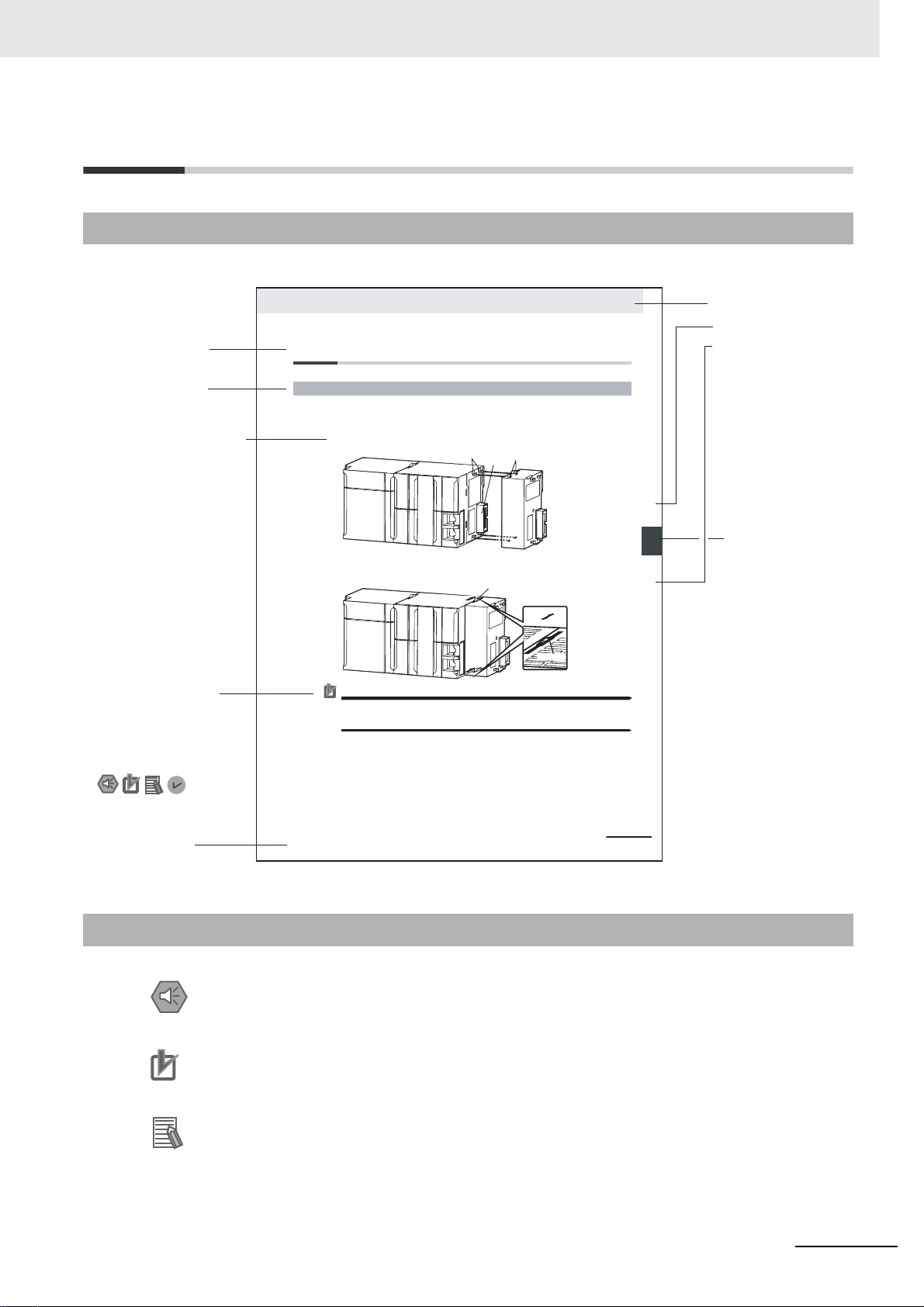
Manual Structure
Page Structure
The following page structure is used in this manual.
Manual Structure
Level 2 heading
Level 3 heading
A step in a procedure
Indicates a procedure.
Special information
Icons indicate
precautions, additional
information, or reference
information.
4 Installation and Wiring
4-3 Mounting Units
4-3-1 Connecting Controller Components
The Units that make up an NJ-series Controller ca n b e c o nn ec te d si m pl y b y p re s s in g th e Un i t s t o g e t h e r
and locking the sliders by moving them toward the bac k of th e Un its . Th e E nd Co ver is connecte d in t h e
same way to the Unit on the far right side of the Controller.
1 Join the Units so that the connectors fit exactly.
2 The yellow sliders at the top and bottom of each Unit lock the Units together. Move the sliders
toward the back of the Units as shown below until they click into place.
Precautions for Correct UsePrecautions for Correct Use
The sliders on the tops and bottoms of the Power Supply Unit, CPU Unit, I/O Units, Special I/O
Units, and CPU Bus Units must be completely locked (until they c l ick into place) after connecting
the adjacent Unit connectors.
Hook
Connector
Move the sliders toward the back
until they lock into place.
Hook holes
Release
Lock
Slider
Level 1 heading
Level 2 heading
Level 3 heading
Gives the current
headings.
stinU gnitnuoM 3-4
4
stnenopmoC rellortnoC gnitcennoC 1-3-4
Page tab
Gives the number
of the main section.
Manual name
NJ-series CPU Unit Hardware User’s Manual (W500)
This illustration is provided only as a sample. It may not literally appear in this manual.
Special Information
Special information in this manual is classified as follows:
Precautions for Safe Use
Precautions on what to do and what not to do to ensure safe usage of the product.
Precautions for Correct Use
Precautions on what to do and what not to do to ensure proper operation and performance.
Additional Information
Additional information to read as required.
This information is provided to increase unde rstanding or make operation easier.
CJ-series Serial Communications Units Operation Manual for NJ-series CPU Unit(W494)
4-9
7

Manual Structure
Version Information
Information on differences in specifications and functionality for CPU Units with different unit versions
and for different versions of the Sysmac Studio is given.
Note References are provided to more detailed or related information.
Precaution on Terminology
In this manual, "download" refers to transferring data from the Sysmac Studio to the physical Controller
and "upload" refers to transferring data from the physical Controller to the Sysmac Studio.
For the Sysmac Studio, synchronization is used to both upload and download data. Here , "synchron iz e"
means to automatically compare t he data for the Sysmac Studio on the comp uter with the data in the
physical Controller and tran sfer the data in the direction that is specified by the user .
8
CJ-series Serial Communications Units Operation Manual for NJ-series CPU Unit(W494)

Sections in this Manual
Sections in this Manual
1R
1R
2A
3I
4
5
6
Introduction
Initial Settings and
Allocations of Device
Variable for CJ-series Unit
Installation and
Wiring
Using Protocol
Macros
Serial Gateway
No-protocol Mode
A Standard
System Protocol
Appendices
Index
2A
3I
4
5
6
7
8
Using Modbus-RTU Slave Mode
7
8
9
CJ-series Serial Communications Units Operation Manual for NJ-series CPU Unit(W494)
Loopback Test
Troubleshooting and Maintenance
9
9

CONTENTS
CONTENTS
Introduction ...............................................................................................................1
Relevant Manuals......................................................................................................2
Manual Configuration ...............................................................................................3
Manual Structure.......................................................................................................7
Sections in this Manual ............................................................................................9
CONTENTS...............................................................................................................10
Read and Understand this Manual ........................................................................15
Safety Precautions..................................................................................................18
Precautions for Safe Use........................................................................................23
Precautions for Correct Use...................................................................................29
Regulations and Standards....................................................................................32
Unit Versions ...........................................................................................................35
Related Manuals......................................................................................................37
Revision History......................................................................................................38
Section 1 Introduction
1-1 Using this Manual....................................................................................................................1-2
1-2 Overview................................................................................................................................... 1-3
1-3 Protocol Overview ................................................................................................................... 1-5
1-3-1 Protocol Macros..........................................................................................................................1-6
1-3-2 Loopback Test.............................................................................................................................1-6
1-3-3 Serial Gateway Mode.................................................................................................................. 1-6
1-3-4 No-protocol Mode........................................................................................................................ 1-7
1-3-5 Modbus-RTU Slave Mode...........................................................................................................1-7
1-4 Features.................................................................................................................................... 1-8
1-4-1 Serial Communications Units......................................................................................................1-8
1-4-2 Protocols.....................................................................................................................................1-8
1-5 System Configurations ......................................................... ... ... ... ... .................................... 1-10
1-5-1 Protocol Macro, Serial Gateway, No-protocol, or Modbus-RTU Slave......................................1-10
1-6 Specifications ........................................................................................................................ 1-14
1-6-1 Serial Communications Unit......................................................................................................1-14
1-6-2 General Specifications.................................. ... .................................... ... ..................................1-15
1-7 Selecting the Serial Communications Mode....................................................................... 1-22
10
1-8 Basic Operating Procedure .................................................. ... ... .......................................... 1-23
1-8-1 Overview...................................................................................................................................1-23
1-8-2 Explanation of Procedure. .... .....................................................................................................1-24
CJ-series Serial Communications Units Operation Manual for NJ-series CPU Unit(W494)

CONTENTS
Section 2 Initial Settings and Allocations of Device V ariable f or CJ-
series Unit
2-1 Component Names and Functions ........................................................................................ 2-2
2-2 Data Exchange with the CPU Unit .......................................................................................... 2-8
2-2-1 Data Flow.................................................................................................................................... 2-8
2-2-2 How to Specify and Create Variables ....................................................................................... 2-12
2-3 Device Variable for CJ-series Unit ....................................................................................... 2-14
2-3-1 Allocations of Device Variable for CJ-series Unit......................................................................2-14
2-3-2 Device Variable for CJ-series Unit for System Settings............................................................2-14
2-3-3 Device Variable for CJ-series Unit for Software Switches......................................................... 2-23
2-3-4 Device Variable for CJ-series Unit for Status............................................................................2-24
2-4 System-defined Variable....................................................................................................... 2-34
Section 3 Installation and Wiring
3-1 Installing Serial Communications Units................................................................................ 3-2
3-1-1 System Configuration Precautions ............................................................................................. 3-2
3-1-2 Serial Communications Unit Installation Procedure.................................................................... 3-2
3-1-3 Unit Handling Precautions.......................................................................................................... 3-3
3-2 Wiring ....................................................................................................................................... 3-4
3-2-1 Wiring Precautions ................... ... ... ... .................................... ... .................................... .............. 3-4
3-2-2 Port Types...................................................................................................................................3-4
3-2-3 Communications Modes and Ports.............................................................................................3-4
3-2-4 Connector Pin Layout................................................................................................................. 3-5
3-2-5 Mounting Height and Connector Cover Dimensions................................................................... 3-6
3-2-6 Reducing Electrical Noise for External Wiring............................................................................ 3-7
3-2-7 2-Wire and 4-Wire Connections..................................................................................................3-7
3-2-8 NT-AL001 Link Adapter Settings.................................................................................................3-8
3-2-9 Connections for Protocol Macro, Serial Gatewa y, No-protocol Mode,
and Modbus-RTU Slave Mode....................................................................................................3-9
3-2-10 Connections in Loopback Test...................................................................................... ... ......... 3-18
3-3 RS-232C and RS-422A/485 Wiring ....................................................................................... 3-19
3-3-1 Recommended RS-232C Wiring Examples ....................... ..................................... ... .............. 3-19
3-3-2 Recommended RS-422A/485 Wiring Examples......................................................... .............. 3-20
3-3-3 Wiring RS-232C Connectors on the CJ1W-SCU22/42............................................................. 3-22
3-3-4 Soldering .................................................................................................................................. 3-23
3-3-5 Assembling Connector Hood....................................................................................................3-24
3-3-6 Wiring RS-422A/485 Terminal-block Connectors on the CJ1W-SCU32/42..............................3-25
3-3-7 Connecting to Unit....................................................................... .. ... ........................................ 3-26
Section 4 Using Protocol Macros
4-1 Overview of the Protocol Macro Function............................................................................. 4-2
4-1-1 Protocol Macros..........................................................................................................................4-2
4-1-2 Using the Protocol Macros............................... .. ... ..................................... .. ............................... 4-2
4-1-3 Protocol Structure....................................................................................................................... 4-4
4-1-4 Data Exchange Method for Link Words.................................................................................... 4-10
4-2 Device Variables for CJ-series Unit and System-defined Variables
(Protocol Macro Mode) ... ... ... ................................................................................................. 4-13
4-2-1 Device Variable for CJ-series Unit for System Settings............................................................4-13
4-2-2 Area Descriptions .....................................................................................................................4-15
4-2-3 System-defined Variable............................................................................................... ... ......... 4-21
4-2-4 Devices Variable for CJ-series Unit for Software Switches.......................................................4-22
4-2-5 Device Variables for CJ-series Unit for Status.......................................................................... 4-24
4-2-6 Protocol Status .........................................................................................................................4-32
CJ-series Serial Communications Units Operation Manual for NJ-series CPU Unit(W494)
11

CONTENTS
4-3 Using Protocol Macros..........................................................................................................4-40
4-3-1 Executing Communications Sequences....................................................................................4-40
4-3-2 User Program Example.............................................................................................................4-42
Section 5 Serial Gateway
5-1 Serial Gateway Overview ........................................................................................................5-2
5-1-1 Overview.....................................................................................................................................5-2
5-1-2 Operating Conditions ................................................................ ..................................... .............5-2
5-1-3 Features......................................................................................................................................5-3
5-1-4 Serial Gateway Specifications.....................................................................................................5-4
5-2 Device Variables for CJ-series Unit and System-defined Variables
(During Serial Gateway Mode)................................................................................................5-5
5-2-1 Device Variables for CJ-series Unit f or System Settings......................... ... .................................5-5
5-2-2 System-defined Variable.............................................................................................................5-8
5-2-3 Device Variable for CJ-series Unit for Software Switches...........................................................5-9
5-2-4 Device Variable for CJ-series Unit f or Status..............................................................................5-9
5-3 Using the Serial Gateway...................................................................................................... 5-12
5-3-1 Setting Device Variable for CJ-series Unit for System Settings and Software Switches...........5-12
5-3-2 Sending Messages Using the SendCmd Instruction.................................................................5-14
5-3-3 Using the Serial Gateway Function When Protocol Macros Are Executed...............................5-15
5-4 Protocol Conversion.............................................................................................................. 5-22
5-4-1 Types of Protocol Conversion....................................................................................................5-22
5-4-2 Converting to CompoWay/F................................................... ... ..................................... .. .........5-23
5-4-3 CompoWay/F Connection Examples ........................................................................................5-25
5-4-4 Converting to Modbus-RTU.. ... .. ..................................... ... .. ..................................... ... ... ...........5-26
5-4-5 Converting to Modbus-ASCII .......................................................... .. ... ... ..................................5-28
5-5 Serial Gateway ....................................................................................................................... 5-29
5-5-1 Serial Gateway Execution Timing for Protocol Macros.............................................................5-29
5-5-2 Serial Gateway Timeout Monitoring..........................................................................................5-31
5-5-3 Other Functions.........................................................................................................................5-32
5-6 Communications Frames...................................................................................................... 5-33
5-6-1 CompoWay/F ............................................................................................................................5-33
5-6-2 Modbus-RTU.............................................................................................................................5-34
5-6-3 Modbus-ASCII...........................................................................................................................5-36
Section 6 No-protocol Mode
6-1 Overview................................................................................................................................... 6-2
6-1-1 Definition.....................................................................................................................................6-2
6-1-2 Specifications..............................................................................................................................6-3
6-1-3 Connections for No-protocol Mode .............................................................................................6-4
6-2 Device Variables for CJ-series Unit and System-defined Variables
(No-protocol Mode)6-5
6-2-1 Device Variables for CJ-Series Unit f or System Settings......................................... ... ... .............6-5
6-2-2 System-defined Variable.............................................................................................................6-8
6-2-3 Device Variable for CJ-series Unit for Software Switches...........................................................6-8
6-2-4 Device Variable for CJ-series Unit f or Status..............................................................................6-8
6-2-5 Device Variable for CJ-series Unit for Status (When Sending/Receiving Data
with SerialSend, SerialRcv, or SerialRcvNoClear Instruction) ..................................................6-11
6-3 Using Serial Port I/O Instructions ........................................................................................ 6-12
6-3-1 System Settings...................................................................................... ... ...............................6-12
6-3-2 Instruction Execution Methods.................................................. ... .................................... ... ......6-12
12
CJ-series Serial Communications Units Operation Manual for NJ-series CPU Unit(W494)

Section 7 Using Modbus-RTU Slave Mode
7-1 Modbus-RTU Slave System................. .... ... ... ......................................................................... 7-2
7-1-1 Modbus-RTU Slave System........................................................................................................7-2
7-1-2 Modbus-RTU Specifications....................................................................................................... 7-2
7-1-3 Communicating with NJ-series CPU Units Using Modbus ......................................................... 7-3
7-2 Device Variables for CJ-series Unit and System-defined Variables
(Modbus-RTU Slave Mode) ..................................................................................................... 7-5
7-2-1 Device Variable for CJ-series Unit for System Settings.............................................................. 7-5
7-2-2 System-defined Variable............................................................................................... ... ...........7-8
7-2-3 Device Variable for CJ-series Unit for Software Switches........................................................... 7-8
7-2-4 Device Variable for CJ-series Unit.............................................................................................. 7-9
7-3 Command and Response Details......................................................................................... 7-13
7-3-1 Supported Modbus-RTU Commands ....................................................................................... 7-13
7-3-2 Command and Response Details............................................................................................. 7-14
Section 8 Loopback Test
CONTENTS
8-1 Executing Loopback Tests .....................................................................................................8-2
8-1-1 Overview.....................................................................................................................................8-2
8-1-2 Connection Method.....................................................................................................................8-2
8-1-3 Procedure...................................................................................................................................8-2
8-1-4 Indicators Used for the Loopback Test......................................... .. ... ..................................... ..... 8-3
8-2 Device Variable for CJ-series Unit (Loopback Test)............................................................. 8-4
8-2-1 Device Variables for CJ-Series Unit for System Settings............................................................8-4
8-2-2 Device Variables for CJ-Series Unit for Status ...........................................................................8-5
Section 9 Troubleshooting and Maintenance
9-1 Indicator Error Displays.......................................................................................................... 9-2
9-2 Communications Status Error Notification........................................................................... 9-3
9-2-1 Status Area Error Information.....................................................................................................9-3
9-3 Troubleshooting....................................................................................................................... 9-4
9-3-1 Serial Gateway (Serial Gateway or Protocol Macro Mode)................................ ... ......................9-4
9-3-2 No-protocol Mode.....................................................................................................................9-10
9-3-3 Protocol Macros........................................................................................................................9-16
9-3-4 Modbus-RTU Slave Mode.........................................................................................................9-22
9-4 Error Logs .............................................................................................................................. 9-25
9-4-1 Error Log Data..........................................................................................................................9-25
9-4-2 Error Contents and Details .......................................................................................................9-26
9-4-3 Error Codes and Troubleshooting.............................................................................................9-28
9-5 Event Logs ............................................................................................................................. 9-30
9-5-1 Overview of the Event Logs......................................................................................................9-30
9-5-2 Error Table ................................................................................................................................ 9-30
9-5-3 Error Descriptions..................................................................................................................... 9-36
9-6 Cleaning and Inspection.......................................................................................................9-53
9-6-1 Cleaning....................................................................................................................................9-53
9-6-2 Inspection .................................................................................................................................9-53
9-7 Replacement Precautions . ... .... ............................................................................................. 9-55
9-7-1 Precautions when Replacing Unit............................................................................................. 9-55
9-7-2 Settings after Replacing Unit.................................................................................................... 9-55
9-7-3 Replacing the Unit....................................................................................................................9-56
CJ-series Serial Communications Units Operation Manual for NJ-series CPU Unit(W494)
13

CONTENTS
A Standard System Protocol
R-1 Reading Reference Documents..............................................................................................R-3
R-1-1 Using Standard System Protocols ............................................................. ... .............................R-3
R-1-2 Standard System Protocols........................................................................................................ R-6
R-2 CompoWay/F Master Protocol................................................................................................R-7
R-2-1 CompoWay/F ............................................................................................................................. R-7
R-2-2 Communications Specifications................................................................................................. R-8
R-2-3 Transmission Procedure.............................................................................................................R-8
R-2-4 Command and Response Formats............................................................................................ R-8
R-2-5 CompoWay/F Master Protocol Sequences.............................................................................. R-12
R-2-6 CompoWay/F Message Frames and PMCR(260) Operands...................................... ... .......... R-12
R-2-7 Send/Receive with ASCII Conversion and with Response......................................................R-13
R-2-8 Structure of the Protocol .............................................................. ... .. ....................................... R-13
R-2-9 Connections.............................................................................................................................R-38
R-3 Mitsubishi Computer Link Master
(A-compatible 1C Frame, Model 1)R-41
R-3-1 Communications Specifications............................................................................................... R-41
R-3-2 Command/Response Formats.................................................................................................R-42
R-3-3 Command Frame Contents......................................................................................................R-43
R-3-4 Mitsubishi Computer Link Master Protocol Sequences............................................................ R-43
R-3-5 Structure of the Protocol .............................................................. ... ......................................... R-43
R-4 V500/V520 Bar Code Reader Protocol .................................................................................R-65
R-4-1 Connections.............................................................................................................................R-65
R-4-2 System Setting.................................................................................. ... .................................... R-66
R-4-3 Protocol Configuration.............................................................................................................. R-67
R-5 3Z4L Laser Micrometer Protocol.......................................... ... ... ... ... .... ... ... ... .... ... ... ... ... .... ...R-78
R-5-1 Connections.............................................................................................................................R-78
R-5-2 List of Operations with Laser Micrometer (5000/6000 Series)................................................. R-81
R-5-3 Protocol Configuration.............................................................................................................. R-83
R-6 Hayes Modem AT Command Protocol ...............................................................................R-117
R-6-1 Protocol Configuration............................................................................................................ R-117
R-6-2 Connections...........................................................................................................................R-119
R-6-3 Compatible Modems.................................................................... .................................... ...... R-119
R-6-4 Modem Settings........................... ............................... ... ........................................................R-120
R-6-5 Communication Errors...........................................................................................................R-125
Appendices
A-1 Differences in Available Functions Depending on the CPU Unit (NJ or CJ Series) ..........A-2
A-1-1 Functional Differences ................................................................................................................A-2
A-1-2 Differences in Methods for Access from a User Program...........................................................A-3
A-2 Version Information...............................................................................................................A-12
Index
14
CJ-series Serial Communications Units Operation Manual for NJ-series CPU Unit(W494)

Read and Understand this Manual
Read and Understand this Manual
Please read and understand this manual before using the products. Please consult your OMRON
representative if you have any questions or comments.
Warranty and Limitations of Liability
WARRANTY
OMRON's exclusive warranty is that the products are free from defects in materials and workmanship for a
period of one year (or other period if specified) from date of sale by OMRON.
OMRON MAKES NO WARRANTY OR REPRESENTATION, EXPRESS OR IMPLIED, REGARDING NONINFRINGEMENT, MERCHANTABILITY, OR FITNESS FOR PARTICULAR PURPOSE OF THE
PRODUCTS. ANY BUYER OR USER ACKNOWLEDGES THAT THE BUYER OR USER ALONE HAS
DETERMINED THAT THE PRODUCTS WILL SUITABLY MEET THE REQUIREMENTS OF THEIR
INTENDED USE. OMRON DISCLAIMS ALL OTHER WARRANTIES, EXPRESS OR IMPLIED.
LIMITATIONS OF LIABILITY
OMRON SHALL NOT BE RESPONSIBLE FOR SPECIAL, INDIRECT, OR CONSEQUENTIAL DAMAGES,
LOSS OF PROFITS OR COMMERCIAL LOSS IN ANY WAY CONNECTED WITH THE PRODUCTS,
WHETHER SUCH CLAIM IS BASED ON CONTRACT, WARRANTY, NEGLIGENCE, OR STRICT
LIABILITY.
In no event shall the re sponsibility of OMRON f or any act e xceed the individual price of the product on which
liability is asserted.
IN NO EVENT SHALL OMRON BE RESPONSIBLE FOR WARRANTY, REPAIR, OR OTHER CLAIMS
REGARDING THE PRODUCTS UNLESS OMRON'S ANALYSIS CONFIRMS THAT THE PRODUCTS
WERE PROPERLY HANDLED, STORED, INSTALLED, AND MAINTAINED AND NOT SUBJECT TO
CONTAMINA TION, ABUSE, MISUSE, OR INAPPROPRIATE MODIFICATION OR REPAIR.
CJ-series Serial Communications Units Operation Manual for NJ-series CPU Unit(W494)
15

Read and Understand this Manual
Application Considerations
SUITABILITY FOR USE
OMRON shall not be responsible for conformity with any standards, codes, or regulations that apply to t he
combination of products in the customer's application or use of the products.
At the customer's request, OMRON will provide applicable third party certification documents identifying
ratings and limitations of use that apply to the products. This info rmation by itself is not sufficient for a
complete determination of the suitability of the products in combination with the end product, machine,
system, or other application or use.
The following are some examples of applications for which particular attention must be given. This is not
intended to be an e xhaustive list of all possible uses of the products, nor is it intended to imp ly th at the uses
listed may be suitable for the products:
• Outdoor use, uses involving potential chemical contamination or electrical interference, or conditions or
uses not described in this manual.
• Nuclear energy control systems, combustion systems, railroad systems, aviation systems, medical
equipment, amusement machines, vehicles, safety equipment, and installations subject to separate
industry or government regulations.
• S ystems, machines, and equipment that could present a risk to life or property.
Please know and observe all prohibitions of use applicable to the produ cts.
NEVER USE THE PRODUCTS FOR AN APPLICATION INVOLVING SERIOUS RISK TO LIFE OR
PROPERTY WITHOUT ENSURING THAT THE SYSTEM AS A WHOLE HAS BEEN DESIGNED TO
ADDRESS THE RISKS, AND THAT THE OMRON PRODUCTS ARE PROPERLY RATED AND
INSTALLED FOR THE INTENDED USE WITHIN THE OVERALL EQUIPMENT OR SYSTEM.
PROGRAMMABLE PRODUCTS
OMRON shall not be responsible for the user's programming of a programmable product, or any
consequence thereof.
16
CJ-series Serial Communications Units Operation Manual for NJ-series CPU Unit(W494)

Read and Understand this Manual
Disclaimers
CHANGE IN SPECIFICATIONS
Product specifications and accessories may be changed at any time based on improvements and other
reasons.
It is our practice to change model numbers when published ratings or features are changed, or when
significant construction changes are made. However, some specificat ions of the products may be changed
without any notice. When in doubt, special model numbers may be assigned t o fix or establish key
specifications for y our application on your request. Ple ase consult with your OMRON representative at any
time to confirm actual specifications of purchased products.
DIMENSIONS AND WEIGHTS
Dimensions and weights are nominal and are not t o be used for manufacturing purposes, even when
tolerances are shown.
PERFORMANCE DATA
Perf ormance data given in this manual is provided as a guide fo r the user in determining suitability and does
not constitute a warranty. It may represent the result of OMRON's test conditions, and the users must
correlate it to actual application requirements. Actual performance is subject to the OMRON Warranty and
Limitations of Liability.
ERRORS AND OMISSIONS
The information in this manual has been carefully checked and is believed to be accurate; however, no
responsibility is assumed for clerical, typographical, or proofreading errors, or omissions.
CJ-series Serial Communications Units Operation Manual for NJ-series CPU Unit(W494)
17
Safety Precautions
Safety Precautions
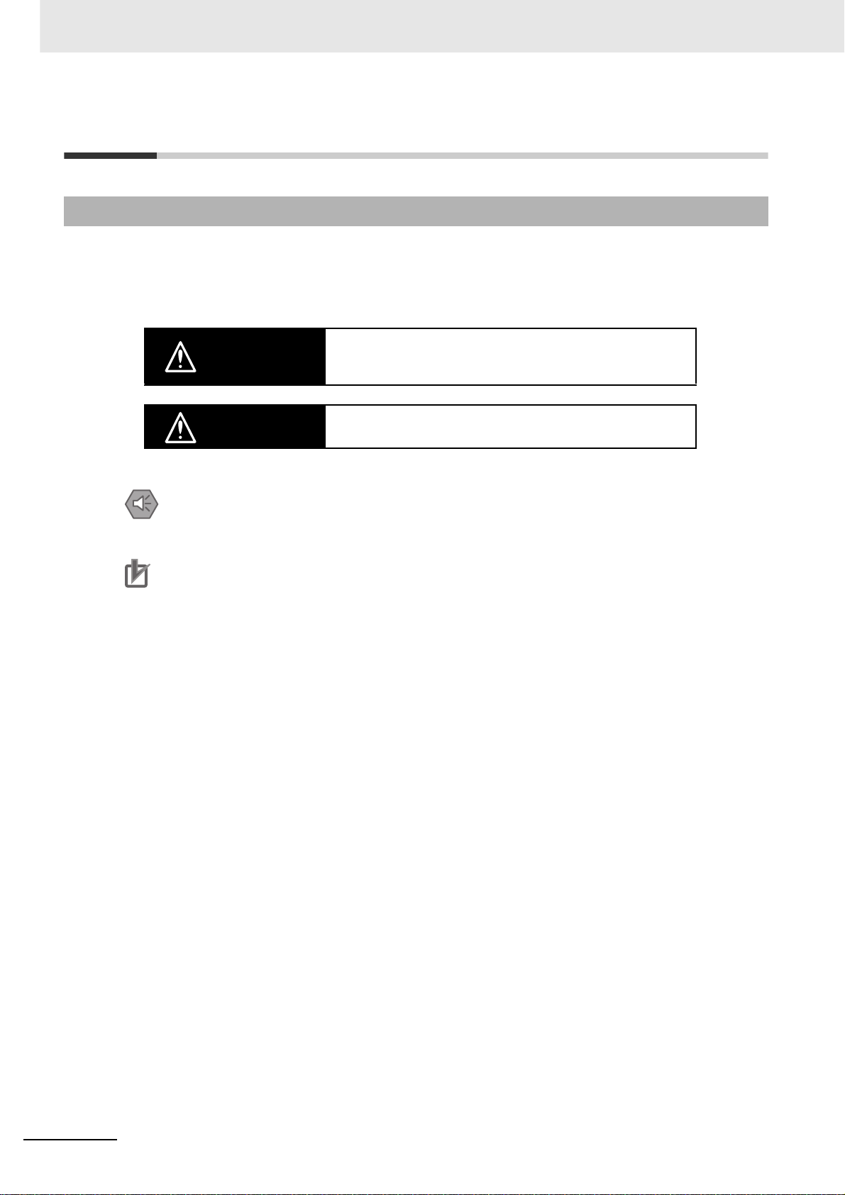
Definition of Precautionary Information
The following notation is used in this manual to provide precautions required to ensure safe usage of a
CJ-series Serial Communications Unit. The safety precautions that are provided are extremely important to safety. Always read and heed the information provided in all safety precautions.
The following notation is used.
Indicates a potentially hazardous situation which, if not avoided,
WARNING
could result in death or serious injury . Additionally, there may be
severe property damage.
Caution
Precautions for Safe Use
Indicates precautions on what to do and what not to do to ensure safe usage of the product.
Precautions for Correct Use
Indicates precautions on what to do and what not to do to ensure proper operation and pe rformance.
Indicates a potentially hazardous situation which, if not avoided,
may result in minor or moderate injury, or property damage.
18
CJ-series Serial Communications Units Operation Manual for NJ-series CPU Unit(W494)
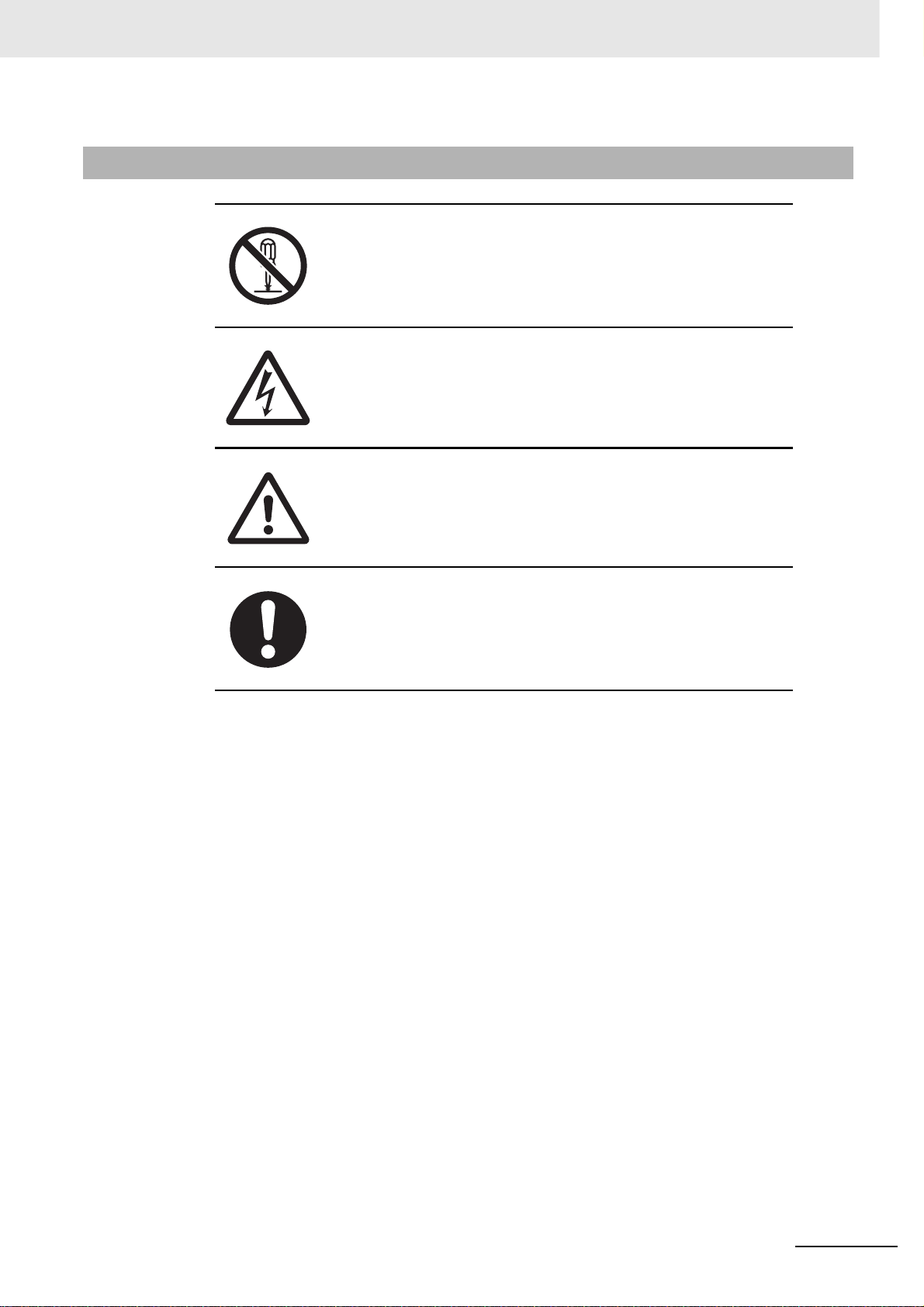
Symbols
Safety Precautions
The circle and slash symbol indicates operations that you must not do.
The specific operation is shown in the circle and explained in text.
This example indicates prohibiting disassembly.
The triangle symbol indicates precautions (including warnin gs).
The specific operation is shown in the triangle and explained in text.
This example indicates a precaution for electric shock.
The triangle symbol indicates precautions (including warnin gs).
The specific operation is shown in the triangle and explained in text.
This example indicates a general precaution.
The filled circle symbol indicates operations that you must do.
The specific operation is shown in the circle and explained in text.
This example shows a general precaution for something that you must do.
CJ-series Serial Communications Units Operation Manual for NJ-series CPU Unit(W494)
19
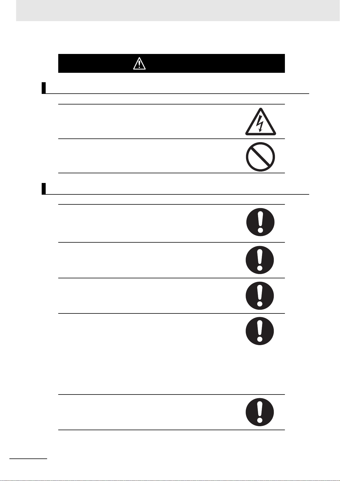
Safety Precautions
During Power Supply
Do not touch any of the terminals or terminal blocks while the power is being
supplied. Doing so may result in electric shock.
Do not attempt to take any Unit apart. In particular, high-voltage parts are
present in the Power Supply Unit while power is supplied or immediately after
power is turned OFF. Touching any of these parts may result in electric
shock. There are sharp parts inside the Unit that may cause injury.
WARNING
Fail-safe Measures
Provide safety measures in external circuits to ensure safety in the system if
an abnormality occurs due to malfunction of the CPU Unit, other Units, or
slaves or due to other external factors affecting operation. Not doing so may
result in serious accidents due to incorrect operation.
Emergency stop circuits, interlock circuits, limit circuits, and similar safety
measures must be provided in external control circuits.
The Controller outputs may remain ON or OFF due to deposition or burning
of the output relays or destruction of the output transistors. As a countermeasure for such problems, external safety measures must be provided to
ensure safe operation of the system.
The CPU Unit will turn OFF all outputs from Basic Output Units in the following cases. The remote I/O slaves will operate according to the settings in the
slaves.
• If an error occurs in the power supply
• If the power supply connection becomes faulty
• If a CPU watchdog timer error or CPU reset occurs
• If a major fault level Controller error occurs
• While the CPU Unit is on standby until RUN mode is entered after the
power is turned ON
External safety measures must be provided to ensure safe operation of the
system in such cases.
20
If external power supplies for slav es or other de vices are o v erloaded or shortcircuited, the voltage will drop, outputs will turn OFF, and the system may be
unable to read inputs. Provide external safety measures in controls with monitoring of external power supply voltage as required so that the system operates safely in such a case.
CJ-series Serial Communications Units Operation Manual for NJ-series CPU Unit(W494)
WARNING
Fail-safe Measures
Unintended outputs may occur when an error occurs in variable memory or
in memory used for CJ-series Units. As a countermeasure for such problems, external safety measures must be provided to ensure safe operation of
the system.
Provide measures in the communications system and user program to
ensure safety in the overall system even if errors or malfunctions occur in
data link communications or remote I/O communications.
Safety Precautions
If there is interference in remote I/O communications or if a major fault level
error occurs, output status will depend on the products that are used.
Confirm the operation that will occur when there is interference in communications or a major fault level error, and implement safety measures.
Correctly set all of the EtherCAT slaves.
The NJ-series Controller continues normal operation for a certain period of
time when a momentary power interruption occurs. This means that the NJseries Controller may receive incorrect signals from external devices that are
also affected by the power interruption. Accordingly, take suitable actions,
such as external fail-safe measures and interlock conditions, to monitor the
power supply voltage of the external device as required.
You must take fail-safe measures to ensure safety in the event of incorrect,
missing, or abnormal signals caused by broken signal lines, momentary
power interruptions, or other causes. Not doing so may result in serious accidents due to incorrect operation.
Voltage and Current Inputs
Make sure that the voltages and currents that are input to the Units and
slaves are within the specified ranges.
Inputting voltages or currents that are outside of the specified ranges may
cause accidents or fire.
Downloading
Always confirm safety at the destination before you transfer a user program,
configuration data, setup data, device variable s, or values in memory used
for CJ-series Units from the Sysmac Studio. The devices or machines may
perform unexpected operation regardless of the operating mode of the CPU
Unit.
CJ-series Serial Communications Units Operation Manual for NJ-series CPU Unit(W494)
21
Safety Precautions
Application
Do not touch any Unit when power is being supplied or immediately after the
power supply is turned OFF. Doing so may result in burn injury.
Wiring
Be sure that all terminal screws and cable connector screws are tightened to
the torque specified in the relevant manuals. The loose screws may result in
fire or malfunction.
Caution
Online Editing
Execute online editing only after confirming that no adverse effects will be
caused by deviations in the timing of I/O. If you perform online editing, the
task execution time may exceed the task period, I/O may not be refreshed
with external devices, input signals may not be read, and output timing may
change.
22
CJ-series Serial Communications Units Operation Manual for NJ-series CPU Unit(W494)

Precautions for Safe Use
Disassembly and Dropping
• Do not attempt to disassemble, repair, or modify any Units. Doing so may result in malfunction or fire.
• Do not drop any Unit or subject it to abno rmal vibration or shoc k. Doing so ma y r esult in Unit malfunction or burning.
Mounting
• The sliders on the tops and bottoms of the Power Supply Unit, CPU Unit, I/O Units, and other Units
must be completely locked (until they clic k into place) after connecting the adjacent Unit connectors.
Installation
Precautions for Safe Use
• Always conn ect to a ground of 100 Ω or less when installing the Units. A g round of 100 Ω or less must
be installed when shorting the GR and LG terminals on the Power Su pply Unit.
Wiring
• Follow the instructions in this manual to correctly perform wiring.
Double-check all wiring and switch settings before turning ON the power supply.
• Use crimp terminals for wiring.
Do not connect bare stranded wires directly to terminals.
• Do not pull on the cables or bend the cables beyond their natural limit.
Do not place heavy objects on top of the cables or other wiring lines. Doing so may break the cables.
• Mount terminal blocks and connectors only after checking the mou nting location carefully.
• Be sure that the terminal blocks, expansion cables, and other items with locking devices are properly
locked into place.
• Always remove any dustproof labels that are on the top of the Units when they are shipped before
you turn ON the power supply. If the labels are not removed, heat will accumulate and malfunctions
may occur.
• Before you connect a computer to the CPU Unit, disconnect the power supply plug of the computer
from the AC outlet. Also, if the computer has an FG terminal, make the connections so that the FG
terminal has the same electrical potential as the GR terminal on the Power Supply Unit. A difference
in electric potential between the computer and Controller may cause failure or malfunction.
• If the external power sup ply to an O utput Un it or sla ve has polarity, connect it with the corr ect pola rity.
If the polarity is reversed, current may flow in the reverse direction and damage the connected
devices regardless of the operation of the Controller.
Power Supply Design
• Do not exceed the rated supply capacity of the Power Supply Units in the NJ-series Controller. The
rated supply capacities are given in the NJ-series CPU Unit Hardware User's Manual
(Cat. No. W500).
If the capacity is exceeded, operation may stop, malfunctions may occur, or data may not be backed
up normally for power interruptions.
Use NJ-series Power Supply Units for both the NJ-series CPU Rack and Expansion Racks.
Operation is not possible if a CJ-series Power Supply Unit is used with an NJ-series CPU Unit or an
NJ-series Power Supply Unit is used with a CJ-series CPU Unit.
CJ-series Serial Communications Units Operation Manual for NJ-series CPU Unit(W494)
23

Precautions for Safe Use
• Do not apply voltages or connect loads to the Output Units or slaves in excess of the maximum ratings.
• Surge current occurs when the power supply is turned ON. When selecting fuses or breakers for
external circuits, consider the above precaution and allow sufficient margin in shut-off performance.
Refer to the relevant manuals for surge current specifications. Refer to the NJ-series CPU Unit Hard-
ware User 's Manual (Cat. No. W500) for surge current specifications.
• If the full dielectric strength voltage is applied or turned OFF using the s witch on the tester, the generated impulse voltage may damage the Power Supply Un it. Use the a djustmen t on the t est er t o gradually increase and decrease the voltage.
• Apply the voltage between the Power Supply Unit's L1 or L2 terminal and the GR terminal when testing insulation and dielectric strength.
• Do not supply AC power from an inverter or other device with a square-wave output. Int ernal temperature rise may result in smoking or burning. Always input a sinusoidal wave with the frequency that is
given in the NJ-series CPU Unit Hardware User's Manual (Cat. No. W500).
• Install external breakers and take other safety measures against short-circuiting in external wiring.
Turning ON the Power Supply
• It takes up to approximately 10 to 20 s to enter RUN mode after the power is turned ON. During that
time, outputs will be OFF or will be the values specified in the Unit or slave settings, and external
communications cannot be perf ormed. Use the R UN output on t he Power Supply Unit, for example , to
implement fail-safe circuits so that external devices do not operate incorrectly.
• Configure the external circuits so that the power supply to the control system turns ON only after the
power supply to the Cont roller h as turned ON. If the power supply to the Controll er is t urned ON after
the control power supply , temporary errors may result in incorrect control system signals because the
output terminals on Ou tput Units may momentarily turn ON when power supply is turned ON to the
Controller.
• If you transfer data from a backup file on an SD Memory Card to the Controller when the power supply is turned ON, proper ly select the da ta groups to transfer. If the data for an unintended data group
is transferred to the Controller, it may cause the equipment to operate unpredictably.
Actual Operation
• Check the user program, data, and parameter settings for proper execution before you use them for
actual operation.
Turning OFF the Power Supply
• Never turn OFF the power supply to the Controller whe n the BUSY indicator is flashing. While the
BUSY indicator is lit, the user program and settings in the CPU Unit are being backed up in the builtin non-volatile memory. This data will not be backed up correctly if the power supply is turned OFF.
Also, a major fault level Controller error will occur the next time you start operation, and operation will
stop.
• Do not turn OFF the power supply or remo ve the SD Memory Card while SD Memory Card access is
in progress (i.e., while the SD BUSY indicator flashes). Data ma y become corrupted, and the Controller will not operate correctly if it uses corrupted data. To remove the SD Memory Card from the CPU
Unit while the power supply is ON, press the SD Memory Card power supply switch and wait for the
SD BUSY indicator to turn OFF before you remove the SD Memory Card.
• Do not disconnect the cable or turn OFF the power supply to the Controller when downloading data
or the user program from Support Software.
• Always turn OFF the power supply to the Controller before you attempt any of the following.
• Mounting or removing I/O Units or the CPU Unit
• Assembling the Units
• Setting DIP switches or rotary switches
24
CJ-series Serial Communications Units Operation Manual for NJ-series CPU Unit(W494)

Precautions for Safe Use
• Connecting cables or wiring the system
• Connecting or disconnecting the connectors
The Power Supply Unit may continue to supply power to the rest of the Controller for a few seconds
after the power supply turns OFF. The PWR indicator is lit during this time. Confirm that the PWR
indicator is not lit before you perform any of the above.
Operation
• Confirm that no adverse effect will occur in the system before you attempt any of the following.
• Changing the operating mode of the CPU Unit (including changing the setting of the Operating
Mode at Startup)
• Changing the user program or settings
• Changing set values or present values
• Forced refreshing
• Always sufficiently check the safety at the connected devices before you change the settings of an
EtherCAT slave or Special Unit.
• If two different function modules are used together, such as when you use CJ-series Basic Output
Units and EtherCAT slave outputs, take suitable measures in the user program and external controls
to ensure that safety is maintained in the controlled system if on e of the fu nctio n mod ules stop s. The
relevant outputs will stop if a partial fault level error occurs in one of the function modules.
• Always confirm safety at the connected equipment before you reset Controller errors with an event
level of partial fault or higher for the EtherCAT Master Function Module.
When the error is reset, all slaves that were in any state other than Operational state due to a Controller error with an event le vel of partial fault or higher (in which outputs are disabled) will go to Operational state and the outputs will be enabled.
Before you reset all errors, confirm that no Controller errors with an event level of partial fault have
occurred for the EtherCAT Master Function Module.
• Always confirm safety at the connected equipment before you reset Controller errors for a CJ-series
Special Unit. When a Controller error is reset, the Unit where the Controller error with an event level
of observation or higher will be restarted.
Before you reset all errors, confirm that no Controller errors with an event level of observation or
higher have occurred for the CJ-series Special Unit. Observation level events do not appear on the
Controller Error Tab Page, so it is possible that you may restart the CJ-series Special Unit without
intending to do so.
You can check the status of the _CJB_UnitErrSta[0,0] to _CJB_UnitErrSta[3,9] error status variables
on a Watch Tab Page to see if an observation level Controller error has occurred.
Battery Backup
• The user program and initial values for the variables are stored in non-volatile memory in the CPU
Unit. The present values of variables with the Retain attribute and the values of the Holding, DM, and
EM Areas in the memory used for CJ-series Units are backed up by a Battery. If the Battery is not
connected or the Batter y is exhausted, the CPU Un it dete cts a Ba ttery-backup Memor y Check Error.
If that error is detected, variables with a Retain attribute are set to their initial values and the Holding,
DM, and EM Areas in memory used for CJ-series Units are cleared to all zeros. Perform thorough
verifications and provide sufficient measures to ensure that the devices perform safe operation for the
initial values of the variables with Retain attributes and the resulting operation.
Debugging
• Forced refreshing ignores the results of user program execution and refreshes I/O with the specified
values. If forced refreshing is used for inputs for which I/O refreshing is not supported, the inputs will
first take the specified values, but they will then be overwritten by the user program. This operation
differs from the force-set/reset functionality of the CJ-series PLCs.
CJ-series Serial Communications Units Operation Manual for NJ-series CPU Unit(W494)
25

Precautions for Safe Use
• You cannot upload or download information for forced refreshing with the Sysmac Studio.
After downloading data that contains forced refreshing, change to RUN mode and then use the Sysmac Studio to perform the operation for forced refreshing.
Depending on the difference in the forced status, the control system may operate unexpectedly.
• Do not specify the same address for the AT specification for more than one variab le.
Doing so would allow the same entity to be accessed with different variable names, which would
make the user program more difficult to understand and possibly cause programming mistakes.
General Communications
• When you use data link communications, check the error information that is given in ErrSta (Controller Error Status) to make sure that no error has occu rred in the source de vice . Write the user progr am
to use the received data only if there is no error. If there is an error in the source device, the data for
the data link may contain incorrect values.
• Unexpected operat ion may result if inappropriate data link tables are set. Even if appro priate data link
tables have been set, confirm that the controlled system will not be adversely affected before you
transfer the data link tables. The data links start automatically after the data link tables are transferred.
• All CPU Bus Units are restarted when routing tables are transferred from Support Software to the
CPU Unit. Confirm that the system will not be adversely affected by restarting before you transfer the
routing tables.
• Tag data links will stop between related nodes while tag data link parameters are transferred during
Controller operation. Confirm that the system will not be adversely affected before you transfer the
tag data link parameters.
EtherNet/IP Communications
• All related EtherNet/IP nodes are reset when you transfer settings for the built-in EtherNet/IP port
(including IP addresses and tag data links settings). Confirm that the system will not be adversely
affected by resetting nodes before you transfer the settings.
• If EtherNet/IP tag data links (cyclic communications) are used with a repeating hub, the communications load on the network will increase. This will increase collisions and may prevent stab le comm unications. Do not use repeating hubs on networks where tag data links are used. Use an Ethernet
switch instead.
EtherCAT Communications
• Make sure that the comm unications distance , n umber of nod es connected, and met hod of connect ion
for EtherCAT are within specifications.
Do not connect EtherCAT communications to EtherNet/IP, a standard in-house LAN, or other networks. An overload may cause the network to fail or malfunction.
• Malfunctions or unexpected operation may occur for some combinations of EtherCAT revisions of the
master and slaves . If y ou disab le the revision check in the network settings, use the Sysmac Studio to
check the slave revision settings in the master and the actual slave revisions, and then make sure
that functionality is compatible in the slave manuals or other references. You can check the actual
slave revisions from the Sysmac Studio or on slave nameplates.
• After you transfer the user program, the CPU Unit is restarted and communications with the EtherCAT slaves are cut off. During that period, the slave outputs behave according to the slave settings.
The time that communications are cut off depends on the EtherCAT network configuration. If the
EtherCAT network configuration contains only OMRON EtherCAT slaves, communications are cut off
for a maximum of 45 seconds.
Before you transfer the user program, confirm that the system will not be adversely affected.
26
CJ-series Serial Communications Units Operation Manual for NJ-series CPU Unit(W494)

Precautions for Safe Use
• If the Fail-soft Operation parameter is set to stop operation, process data communications will stop
for all slav es when an EtherCAT communications error is detected in a slave. For this reason, if Servo
Drives are connected, the Servos for all axes will be turned OFF. Make sure that the Fail-soft Operation parameter setting results in safe operation when a device error occurs.
• EtherCAT communications are not always established immediately after the power supply is turned
ON. Use the system-defined variables in t he user prog ra m to confirm that communication s are established before attempting control operations.
• If frames sent to EtherCAT slaves are lost due to noise or other causes, slave I/O data is not communicated, and the intended operation is sometimes not achieved. If noise countermeasures are
required, use the _EC_InDataInvalid (Input Data Disable) system-defined variable as an interlock
condition in the user program.
Refer to the NJ-series CPU Unit Built-in EtherCAT Port User's Manual (Cat. No. W505) for details.
The slave outputs behave according to the slave settings. Refer to the manuals for the slaves for
details.
• When an EtherCAT slave is disconnected, communications will stop and control of the outputs will be
lost not only for the disconnected slave, but for all slaves connected after it. Confirm that the system
will not be adversely affected before you disconnect a slave.
• If you disconnect the cable from an EtherCAT slave to disconnect it from the network, any current
communications frames may be lost. If frames are lost, slave I/O data is not communicated, and the
intended operation is sometimes not achieved. Perform the following processing for a slave that
needs to be replaced.
Program the _EC_InDataInvalid (Input Data Disable) system-defined variable as an interlock con-
dition.
Set the Impermissible Number of Continuous Timeouts setting in the EtherCAT master to at least
2.
Refer to the NJ-series CPU Unit Built-in EtherCAT Port User's Manual (Cat. No. W505) for details.
Motion Control
• Confirm the axis number carefully before you perform an MC Test Run.
• The motor is stopped if communications are interrupted between the Sysmac Studio and the CPU
Unit during an MC Test Run. Connect the communications cable between the computer and CPU
Unit securely and confirm that the system will not be adversely affected before you perform an MC
Test Run.
• Always execute the Save Cam Table instruction if you change an y of the cam data from the user program in the CPU Unit or from the Sysmac Studio. If the cam data is not saved, the previous condition
will be restored when the power is turned ON again, possibly causing unexpected machine operation.
• The positive drive prohibit input (POT), negative dr ive prohibit input (NOT), and home proximity input
(DEC) of the Servo Drive are used by the MC Function Module as the positive limit input, negative
limit input, and home proximity in put. Mak e sure that the signal widt hs f or all of these input signals are
longer than the control period of the MC Function Module. If the input signal widths are shorter than
the control period, the MC Function Module may not be able to detect the input signals, resulting in
incorrect operation.
Battery Replacement
• The Battery may leak, rupture, heat, or ign ite. Ne v er short-circuit, charge, disassemb le , heat, or incinerate the Battery or subject it to strong shock.
• Dispose of any Battery that has been dropped on the floor or other wise subjected to excessive shock.
Batteries that have been subjected to shock may leak if they are used.
• UL standards require that only an experienced engineer replace the Battery. Make sure that an experienced engineer is in charge of Battery replacement.
• Apply power for at least five minutes before changing the Batter y. Install a new Battery within five
minutes (at 25°C) of turning OFF the power supply. If power is not supplied for at least 5 minutes, the
saved data may be lost.
CJ-series Serial Communications Units Operation Manual for NJ-series CPU Unit(W494)
27

Precautions for Safe Use
Unit Replacement
• We recommend replacing the Battery with the power turned OFF to prevent the CPU Unit's sensitive
internal components from being damaged by static electricity and to prevent malfunctions. The Battery can be replaced without turning OFF the power supply. To do so, always touch a grounded piece
of metal to discharge static electricity from your body before yo u start the procedure.
After you replace the Battery, connect the Sysmac Studio and clear the Low Battery Voltage error.
• Make sure that the required data, including the user program, configurations, settings, variables, and
memory used for CJ-series Units, is transferred to a CPU Unit that was replaced and to externally
connected devices before restarting operation.
Be sure to include the routing tables, network parameters, and other CPU Bus Unit data, which are
stored in the CPU Unit.
Disposal
• Dispose of the product and Batteries according to local ordinances as they apply.
• The following information must be display ed for all products that contain primary lithium batteries with
a perchlorate content of 6 ppb or higher when shipped to or transported through the State of California, USA.
Perchlorate Material - special handling may apply.
See www.dtsc.ca.gov/hazardouswaste/perchlorate.
• The CPU Unit contains a primary lithium battery with a perchlorate content of 6 ppb or higher. Place
the above information on the individual boxes and shipping boxes when shipping finished products
that contain a CPU Unit to the State of California, USA.
Using Serial Communications Unit
• When connecting RS-422A/485, always check the polarity before you make connections. The signal
names SDA/B and RDA/B do not always have the same polarity.
• Do not turn OFF the power supply while writing the protocol macro data.
• Do not connect the 5-V power supply on pin 6 of the RS-232C port on the Unit to any external de vice
other than an NT-AL001 Link Adapter. Otherwise, the e xternal de vice and the Se rial Communication s
Unit may be damaged.
• Use the OMRON Cables specified in this manual or make your own cables. Do not use commercially
available RS-232C cables sold for personal computers. Otherwise, the external device and the Serial
Communications Unit may be damaged .
• When the Serial Gateway is executed during protocol macro execution, the communications
sequence contents and the command reception timing may suspend step transition of the communications. Use the Serial Gateway send start timeout function to monitor at the command source
whether step transition in the com munications sequence was suspended due to execution of Serial
Gateway. If sending of he command of each protocol does not start within the set time, either retry
execution of the command or change the communications sequence.
• When you use 2-wire RS-422A/485 communications in Protocol Macro Mode, set only modem controls for the transmission control parameters, and do not use RS/CS flow controls.
• An instruction error will occur if you execute the SerialSend, SerialRcv, or Ser ialRcvNoClear instr uction for a serial communications port that is in any mode other than No-protocol Mode.
28
CJ-series Serial Communications Units Operation Manual for NJ-series CPU Unit(W494)

Precautions for Correct Use
Storage, Mounting, and Wiring
• Do not operate or store the Controller in the following locations. Operation may stop or malfunctions
may occur.
• Locations subject to direct sunlight
• Locations subject to temperatures or humidity outside the range specified in the specifications
• Locations subject to condensation as the result of severe changes in temperature
• Locations subject to corrosive or flammable gases
• Locations subject to dust (especially iron dust) or salts
• Locations subject to exposure to water, oil, or chemicals
• Locations subject to shock or vibration
• Take appropriate and sufficient countermeasures when installing the Controller in the following locations.
• Locations subject to strong, high-freq uency noise
• Locations subject to static electricity or other forms of noise
• Locations subject to strong electromagnetic fields
• Locations subject to possible exposure to radioactivity
• Locations close to power lines
• Before touching a Unit, be sure to first touch a grounded metallic object in order to discharge any
static build-up.
• Install the Controller away from sources of heat and ensure proper ventilation. Not doing so may
result in malfunction, in operation stopping, or in burning.
• An I/O bus check error will occur and the Controller will stop if an I/O Connecting Cable's connector is
disconnected from the Rack. Be sure that the connectors are secure.
• Do not allow foreign matter to enter the openings in the Unit. Doing so may result in Unit burning,
electric shock, or failure.
• Do not allow wire clippings, shavings, or other foreign material to enter any Unit. Otherwise, Unit
burning, failure, or malfunction may occur. Cover the Units or take other suitable counterme asures,
especially during wiring work.
• For EtherCAT and EtherNet/IP, use the connection methods and cables that are specified in the NJ-
series CPU Unit Built-in EtherCAT Port User's Manual (Cat. No. W505) and the NJ-series CPU Unit
Built-in EtherNet/IP Port User's Manual (Cat. No. W506). Otherwise, communications may be faulty.
• Use the rated power supp ly v oltage f or the Power Supply Units. Take appropriate measures to ensure
that the specified power with the rated voltage and frequency is supplied in places where the power
supply is unstable.
• Make sure that the current capacity of the wire is sufficie nt. Otherwise, excessive hea t may be generated. When cross-wiring terminals, the total current for all the terminals will flow in the wire. When
wiring cross-overs, make sure that the current capacity of each of the wires is not exceeded.
• Do not touch the terminals on the P ow er Supp ly Unit immediat ely after turning OFF the po w er supply.
Residual voltage may cause electrical shock.
• If you use reed switches for the input contacts fo r A C I nput Unit s, use switches with a current capacity
of 1 A or greater.
If the capacity of the reed switches is too low, surge current may fuse the contacts.
Precautions for Correct Use
CJ-series Serial Communications Units Operation Manual for NJ-series CPU Unit(W494)
29

Precautions for Correct Use
Error Processing
• In applications that use the results of instructions th at r ead the er ror st at us, consider the aff ect on the
system when errors are detected and program error processing accordingly. For example, even the
detection of a minor error, such as Battery replacement during operation, can affect the system
depending on how the user program is written.
• If you change the event level of a Controller error, the output status when the error occurs may also
change. Confirm safety before you change an event level.
Restoring and Automatically Transferring Data
• When you edit the restore command file or the automatic transfer command file, do not change anything in the file except for the “yes” and “no” specifications for the selectable data groups. If you
change anything else in the file, the Controller may perform unexpected operation when you restore
or automatically transfer the data.
Unit Replacement
• If you replace a CPU Bus Unit or Special I/O Unit, refer to operation manual for the Unit for information on the data required for individual Units and redo the necessary settings.
• The absolute encoder home offset is backed up with a Battery in the CPU Unit.
When you change the combination of the CPU Unit and Servo motor, e.g., when you add or replace a
Servomotor, define home again.
To restore the information without changing the CPU Unit -Servomotor co mbination, r emov e the absolute encoder home offset from the data to restore.
Task Settings
• If a Task Period Exceeded error occurs, shorten the programs to fit in the task period or increase the
setting of the task period.
Motion Control
• Use the system-defined variable in the user program to confirm that EtherCAT communications are
established before you attempt to execute motion control instructions. Motion control instructions are
not executed normally if EtherCAT communications are not established.
• Use the system-defined variables to monitor for errors in communications with the slaves that are
controlled by the motion control function module. Motio n control instructions are not executed normally if an error occur in slave communications.
• Before you start an MC Test Run, make sure that the operation parameters are set correctly.
• Do not download motion control settings during an MC Test Run.
30
EtherCAT Communications
• Do not disconnect the EtherCAT slave cables during operation. The outputs will become unstable.
• Set the Servo Drives to stop operation if an error occurs in EtherCAT communications between the
Controller and a Servo Drive.
• Make sure that all of the slaves to be re stor ed ar e participating in the net w ork before you reset a Network Configuration Verification Error, Process Data Communications Error, or Link OFF Error in the
EtherCAT Master Function Module. If any slave is not participating when any of these errors is reset,
the EtherCAT Master Function Module may access sla v e with a diff eren t node address t han the specified node address or the error may not be reset correctly.
CJ-series Serial Communications Units Operation Manual for NJ-series CPU Unit(W494)

Precautions for Correct Use
Battery Replacement
• Be sure to install a replacement Battery within two years of the productio n date shown on the Battery
label.
• Turn ON the power after replacing the Battery for a CPU Unit that has been unused for a long time.
Leaving the CPU Unit unused again without turning ON the power even once after the Battery is
replaced may result in a shorter Battery life.
• When you replace the Battery, use the CJ1W-BAT01 Battery Set.
SD Memory Cards
• Insert the SD Memory Card all the way.
• Do not turn OFF the power supply to the Contr oller during SD Memo ry Card access. The files may be
corrupted.
If there is a corrupted file in the SD Memory Card, the file is automatically deleted by the restoration
function when the power supply is turned ON.
CJ-series Serial Communications Units Operation Manual for NJ-series CPU Unit(W494)
31

Regulations and Standards
Regulations and Standards
Conformance to EC Directives
Applicable Directives
• EMC Directives
• Low Voltage Directive
Concepts
z EMC Directive
OMRON devices that comply with EC Directives also conform to the related EMC standards so that
they can be more easily built into other devices or the overall machine. The actual products have
been checked for conformity to EMC standards.*
Whether the products conform to the standards in the system used by the customer, however, must
be checked by the customer. EMC-related perf ormance of the OMRON devices that comply with EC
Directives will vary depending on the configuration, wiring, and other conditions of the equipment or
control panel on which the OMRON de vices are installed. The customer must, ther ef ore , perf orm the
final check to confirm that devices and the overall machine conform to EMC standards.
* Applicable EMC (Electromagnetic Compatibility) standards are as follows:
EMS (Electromagnetic Susceptibility): EN 61131-2 and EN 61000-6-2
EMI (Electromagnetic Interference): EN 61131-2 and EN 61000-6-4 (Radiated emission: 10-m regulations)
z Low Voltage Directive
Always ensure that devices operating at voltages of 50 to 1,000 VAC and 75 to 1,500 VDC meet the
required safety standards. The applicable directive is EN 61131-2.
z Conformance to EC Directives
The NJ-series Controllers comply with EC Directives. To ensure that the machine or device in which
the NJ-series Controller is used complies with EC Directives, the Controller must be installed as follows:
• The NJ-series Controller must be installed within a cont rol panel.
• You must use reinforced insulation or double insulation for the DC power supplies connected to
DC Power Supply Units and I/O Units.
• NJ-series Controllers that comply with EC Directiv es al so conform to the Common Emission Standard (EN 61000-6-4). Radiated emission characteristics (10-m regulations) may vary depending
on the configuration of the control panel used, other devices connected to the control panel, wiring, and other conditions.
You must therefore confirm that the overall machine or equipment complies with EC Directives.
32
CJ-series Serial Communications Units Operation Manual for NJ-series CPU Unit(W494)

Regulations and Standards
EMI Measures for Serial Communications Boards and Units
The CS/CJ-series PLCs conform to the Common Emission Standards (EN 61000-6-4 or EN 61131-2)
of the EMC Directives. However, the noise generated from Serial Communications Board or Unit communications cables may not satisfy these standards. In such a case, commercially available ferrite
cores must be placed on the communications cab le or ot her app ropriate count ermeasures must be pr ovided external to the PLC.
z Recommended Ferrite Cores
The following ferrite core (data line noise filter) is recommended:
0443-164151 by Fair-Rite Products Corp.
Low impedance, 25 MHz: 90 Ω, 100 MHz: 160 Ω
z Recommended Mounting Method
Mount the core on one turn of the communications cable, as shown in the following illustration.
Mount the cores as lost to the end of the communications cable as possible, as shown in the following
illustration.
Serial
Communications
Unit/Board
CJ-series Serial Communications Units Operation Manual for NJ-series CPU Unit(W494)
33

Regulations and Standards
Conformance to Shipbuilding Standards
The NJ-series Controllers comply with the following shipbuilding standards. Applicability to the shipbuilding standards is based on certain usage conditions. It may not be possible to use the product in
some locations. Contact your OMRON representative before attempting to use a Controller on a
ship.
Usage Conditions for NK and LR Shipbuilding Standards
• The NJ-series Controller must be installed within a cont rol panel.
• Gaps in the door to the control panel must be completely filled or covered with gaskets or other
material.
• The following noise filter must be connected to the power supply line.
Noise Filter
Manufacturer Model
Cosel Co., Ltd. TAH-06-683
Trademarks
• Sysmac and SYSMAC are trademarks or registered trademarks of OMRON Corporation in Ja pan
and other countries for OMRON factory automation products.
• Windows, Windows 98, Windows XP, Windows Vista, and Windows 7 are regist ered trademarks of
Microsoft Corporation in the USA and other countries.
•EtherCAT is registered trademark and patented technology, licensed by Beckhoff Automation
GmbH, Germany.
• The SD logo is a trademark of SD-3C, LLC.
Other company names and product names in this document are the trademarks or registered trademarks of their respective companies.
34
CJ-series Serial Communications Units Operation Manual for NJ-series CPU Unit(W494)

Unit Versions
Unit V ersions
A "unit version" has been introduced to manage CPU Units in the NJ Series according to differences in
functionality accompanying Unit upgrades.
Notation of Unit Versions on Products
The unit version is given on the ID infor mation label of the products for which unit versions are managed, as shown below.
Example for NJ-series NJ501-@@@@ CPU Unit:
Unit Versions
ID information label
Unit model Unit version
NJ501 - 1500 V er.1.@@
PORT1 MAC ADDRESS: @@@@@@@@@@@@
PORT2 MAC ADDRESS: @@@@@@@@@@@@
Lot No. DDMYY @ xxxx
Lot number and serial number MAC address
The following information is provided on the ID information label.
Item Description
Unit model Gives the model of the Unit.
Unit version Gives the unit version of the Unit.
Lot number and
serial number
MAC address Gives the MAC address of the built-in port on the Unit.
Gives the lot number and serial number of the Unit.
DDMYY: Lot number, @: For use by OMRON, xxxx: Serial number
"M" gives the month (1 to 9: January to September, X: October, Y: November, Z: December)
Confirming Unit Versions with Sysmac Studio
You can use the Unit Production Information on the Sysmac Studio to check th e unit v ersion of the CPU
Unit, CJ-series Special I/O Units, CJ-series CPU Bus Units, and EtherCAT slaves. The unit versions of
CJ-series Basic I/O Units cannot be checked from the Sysmac Studio.
z CPU Unit and CJ-series Units
1 Double-click CPU/Expansion Racks under Configurations and Setup in the Multiview
Explorer. Or, right-click CPU/Expansion Racks under Configurations and Setup and select
Edit from the menu.
The Unit Editor is displayed for the Controller Configurations and Setup layer.
CJ-series Serial Communications Units Operation Manual for NJ-series CPU Unit(W494)
35

Unit Versions
2 Right-click any open space in the Unit Editor and select Production Information.
The Production Information Dialog Box is displayed.
Simple Display Detailed Display
In this example, "Ver.1.00" is displayed ne xt to the unit model.
The following items are displayed.
CPU Unit CJ-series Units
Unit model
Unit version
Lot number
Unit model
Unit version
Lot number
Rack number, slot number, and unit number
z EtherCAT Slaves
1 Double-click EtherCAT under Configurations and Setup in the Multiview Explorer. Or, right-
click EtherCAT under Configurations and Setup and select Edit from the menu.
The EtherCAT Configuration Tab Page is displayed for the Controller Configurations and Setup
layer.
2 Right-click the master in the EtherCAT Configurations Editing Pane and select Display Produc-
tion Information.
The Production Information Dialog Box is displayed.
36
The following items are displayed.
Node address
Type information*
Serial number
* If th e model number cannot be determined (such as when there is no ESI file), the vendor ID, product
code, and revision number are displayed.
CJ-series Serial Communications Units Operation Manual for NJ-series CPU Unit(W494)

Related Manuals
The following manuals are related to the NJ-series Controllers. Use these manuals for reference.
Manual name Cat. No. Model numbers Application Description
NJ-series CPU Unit
Hardware User's Manual
NJ-series CPU Unit Software User's Manual
Sysmac Studio Version 1
Operation Manual
CJ-series Serial Communications Units Operation Manual for NJ-series
CPU Unit (this manual)
Serial Communications
Boards and Serial Communications Units Operation Manual
CX-Protocol Version 1.9
Operation Manual
CX-Integrator
CS/CJ/CP/NSJ-series
Network Configuration
Tool Operation Manual
W500 NJ501-@@@@
NJ301-@@@@
W501 NJ501-@@@@
NJ301-@@@@
W504 SYSMAC-
SE2@@@
W494 CJ1W-SCU@2 Learning about the func-
W336 CS1W-SCB@1-V1
CS1W-SCU@1-V1
CJ1W-SCU@1-V1
CJ1W-SCU@2
W344 --- Learning about the use of
W464 Learning how to configure
Learning the basic specifications of the NJ-series
CPU Units, including introductory information,
designing, installation, and
maintenance. Mainly hardware information is provided.
Learning how to program
and set up an NJ-series
CPU Unit. Mainly software
information is provided.
Learning about the operating procedures and functions of the Sysmac Studio.
tions to use Serial Communications Unit and Boards
with NJ series configuration (hardware and serial
communications mode).
Learning about the standard system protocol with
OMRON components
Learning about the functions to use Serial Communications Unit and Boards
(hardware and serial communications mode) .
Learning about the standard system protocol with
OMRON components
CX-Protocol, which
enables protocol macro
creation.
Learning about the details
of functions of protocol
macros made by users.
networks (data links, routing tables, Communications Unit settings, etc.).
An introduction to the entire NJ-series system is
provided along with the following information on
the CPU Unit.
• Features and system configuration
• Introduction
• Part names and functions
• General specifications
• Installation and wiring
• Maintenance and inspection
Use this manual together with the NJ-series
CPU Unit Software User's Manual (Cat. No.
W501).
The following information is provided on a Controller built with an NJ501 CPU Unit.
• CPU Unit operation
• CPU Unit features
• Initial settings
• Programming based on IEC 61131-3 language specifications
Use this manual together with the NJ-series
CPU Unit Hardware User's Manual (Cat. No.
W500).
Describes the operating procedures of the Sysmac Studio.
Describes the use of Serial Communications
Unit and Boards with NJ-series configuration
(hardware and serial communications mode),
including the usage of standard system protocols. Refer to the CX-Protocol Operation Manual
(Cat. No. W344) for the details of functions of
protocol macros made by users.
Describes the use of Serial Communications
Unit and Boards with CJ-series configuration
(hardware and serial communications mode),
including the usage of standard system protocols. Refer to the CX-Protocol Operation Manual
(Cat. No. W344) for the details of functions of
protocol macros made by users.
Describes 1) the use of the CX-Protocol, and 2)
details on protocol macros.
Use this manual to create protocol macros for
serial communications, or to customize the standard system protocol.
Describes operating procedures for the CX-Integrator.
Related Manuals
CJ-series Serial Communications Units Operation Manual for NJ-series CPU Unit(W494)
37

Revision History
Revision History
A manual revision code appears as a suffix to the catalog number on the front and back covers of the
manual.
Cat. No.
Revision code Date Revised content
01 July 2011 Original production
02 March 2012 Corrected errors.
03 August 2012 Made changes accompanying the upgrade to unit version 2.1.
W494-E1-03
Revision code
38
CJ-series Serial Communications Units Operation Manual for NJ-series CPU Unit(W494)

Introduction
This section introduces the hardware and software functions of the Serial Communications Boards and the Serial Communications Units, including the communications
modes, system configurations, and specifications.
1-1 Using this Manual . . . . . . . . . . . . . . . . . . . . . . . . . . . . . . . . . . . . . . . . . . . . . 1-2
1-2 Overview . . . . . . . . . . . . . . . . . . . . . . . . . . . . . . . . . . . . . . . . . . . . . . . . . . . . . 1-3
1-3 Protocol Overview . . . . . . . . . . . . . . . . . . . . . . . . . . . . . . . . . . . . . . . . . . . . . 1-5
1-3-1 Protocol Macros . . . . . . . . . . . . . . . . . . . . . . . . . . . . . . . . . . . . . . . . . . . . . . . . 1-6
1-3-2 Loopback Test . . . . . . . . . . . . . . . . . . . . . . . . . . . . . . . . . . . . . . . . . . . . . . . . . 1-6
1-3-3 Serial Gateway Mode . . . . . . . . . . . . . . . . . . . . . . . . . . . . . . . . . . . . . . . . . . . . 1-6
1-3-4 No-protocol Mode . . . . . . . . . . . . . . . . . . . . . . . . . . . . . . . . . . . . . . . . . . . . . . 1-7
1-3-5 Modbus-RTU Slave Mode . . . . . . . . . . . . . . . . . . . . . . . . . . . . . . . . . . . . . . . . 1-7
1-4 Features . . . . . . . . . . . . . . . . . . . . . . . . . . . . . . . . . . . . . . . . . . . . . . . . . . . . . 1-8
1-4-1 Serial Communications Units . . . . . . . . . . . . . . . . . . . . . . . . . . . . . . . . . . . . . . 1-8
1-4-2 Protocols . . . . . . . . . . . . . . . . . . . . . . . . . . . . . . . . . . . . . . . . . . . . . . . . . . . . . 1-8
1-5 System Configurations . . . . . . . . . . . . . . . . . . . . . . . . . . . . . . . . . . . . . . . . 1-10
1-5-1 Protocol Macro, Serial Gateway, No-protocol, or Modbus-RTU Slave . . . . . . 1-10
1-6 Specifications . . . . . . . . . . . . . . . . . . . . . . . . . . . . . . . . . . . . . . . . . . . . . . . . 1-14
1-6-1 Serial Communications Unit . . . . . . . . . . . . . . . . . . . . . . . . . . . . . . . . . . . . . 1-14
1-6-2 General Specifications . . . . . . . . . . . . . . . . . . . . . . . . . . . . . . . . . . . . . . . . . . 1-15
1-7 Selecting the Serial Communications Mode . . . . . . . . . . . . . . . . . . . . . . . 1-22
1-8 Basic Operating Procedure . . . . . . . . . . . . . . . . . . . . . . . . . . . . . . . . . . . . . 1-23
1-8-1 Overview . . . . . . . . . . . . . . . . . . . . . . . . . . . . . . . . . . . . . . . . . . . . . . . . . . . . 1-23
1-8-2 Explanation of Procedure . . . . . . . . . . . . . . . . . . . . . . . . . . . . . . . . . . . . . . . 1-24
1
CJ-series Serial Communications Units Operation Manual for NJ-series CPU Unit(W494)
1-1

1 Introduction
1-1 Using this Manual
This manual provides information in the table below as would be required in actual applications. You
should read Section 1 Introduction first. Then read information in the rest of the manual and related
manuals as required by your specific application.
Information Section Item
Overview and appearance of the Unit 1 Introduction 1-2 Overview
2-1 Component Names and Functions
Overview, features, and specifications of
serial communications modes
Basic procedures and operations 1-8 Basic Operating Procedure
Selecting serial communications modes 1-7 Selecting the Serial Communications
System configurations for serial communications modes
Allocations of device variables fo r CJseries Units to the Unit and related system-defined variables
Installing and wiring the Unit 3 Installation and Wiring --Allocations of device variables fo r CJ-
series Units in each serial communications mode
Ladder diagram programming in protocol
macros
Loopback tests for communications
ports
Troubleshooting and maintenance 9 Troubleshooting and Maintenance --The contents of standard system proto-
cols and connection methods to OMRON
components
Details on the protocol macro function CX-Protocol Ver.1. 9 OPERATION Manual (Cat.No. W344)
2 Initial Settings and Allocations of
Device Va riable for CJ-series Unit
4 Using Protocol Macros
5 Serial Gateway
6 No-protocol Mode
7 Using Modbus-RTU Slave Mode
8 Loopback Test
4 Using Protocol Macros 4-3 Using Protocol Macros
8 Loopback Test
Ref A Standard System Protocol ---
1-3 Protocol Overview
1-4 Features
1-6 Specifications
Mode
1-5 System Configurations
2-2 Data Exchange with the CPU Unit
2-3 Device Variable for CJ-series Unit
2-4 System-defined Variable
4-2 Device Variables for CJ-series Unit
and System-defined Variables (Protocol
Macro Mode)
5-2 Device Variables for CJ-series Unit
and System-defined Variables (During
Serial Gateway Mode)
6-2 Device Variables for CJ-series Unit
and System-defined Variables (No-protocol Mode)
7-2 Device Variables for CJ-series Unit
and System-defined Variables (ModbusRTU Slave Mode)
8-2 Device Variable for CJ-series Unit
(Loopback Test)
1-2
CJ-series Serial Communications Units Operation Manual for NJ-series CPU Unit(W494)

1-2 Overview
This section gives an ov erview of the Serial Comm unicat ions Unit.
The Serial Communications Units are CJ-series CPU Bus Units. You can mount one or more U nits to
an NJ-series CPU Rack or an CJ-series Expansion Rack. You can control a total of up to 16 CPU Bus
Units by one CPU Unit. (Serial Communications Units is abbreviated to Units in some sections of this
manual.)
A Serial Communications Unit has two communications ports to connect with host computers, generalpurpose external devices or support software. The Units allow easy expansion of ports for serial communications.
Serial Communications Unit
1 Introduction
1-2 Overview
1
z Models
CJ1W-SCU22
(Two RS-232C ports)
RS-232C port
RS-232C port
CJ1W-SCU32
(Two RS-422A/485 ports)
RS-422A/485 port
RS-422A/485 port
CJ1W-SCU42
(One RS-232C and One RS422A/485 Port)
RS-422A/485 port
RS-232C port
CJ-series Serial Communications Units Operation Manual for NJ-series CPU Unit(W494)
1-3

1 Introduction
Connectable Devices
The following serial communications modes are supported by the Serial Communications Units:
Protocol Macro, No-protocol, Modbus-RTU Slave, and Loopback Test Modes. You can also connect
the devices shown in the following diagram.
General-purpose
external device
Programming
Device
Host computer
Serial Communications Unit
NJ-series PLC
General-purpose
external device
Programming
Device
Host computer
There is another serial communications mode, Serial Gateway, which enables connection with the
following devices.
Modbus-RTU-compatible
device (e.g., Inverter)
Modbus-ASCII-compatible
device (e.g., Servo)
CompoWay/Fcompatible
OMRON
component
Serial
Communications
Unit
Message
CPU Unit
CompoWay/Fcompatible
OMRON
component
Modbus-RTU-compatible
device (e.g., Inverter)
Modbus-ASCII-compatible
device (e.g., Servo)
Protocol
conversion
Protocol
conversion
message
1-4
CJ-series Serial Communications Units Operation Manual for NJ-series CPU Unit(W494)

1-3 Protocol Overview
A Serial Communications Unit is a CPU Bus Unit that provides RS-232C or RS-422A/485 serial communications por ts. You c an use the following five serial communications modes as required for each
serial communications port.
• Protocol Macro: For communications between PLCs and general-purpose external devices
• Serial Gateway
• No-protocol
• Modbus-RTU Slave
• Loopback Test: For testing the communications ports
The Serial Gateway can also be executed in Protocol Macro Mode.
Modbus-ASCII Slave Mode is not supported.
Product Model
number
Serial Communications
Unit
Device to be connected General-pur-
CJ1WSCU22
CJ1WSCU32
CJ1WSCU42
Serial ports Serial communications mode
Protocol
Macro
RS-232C OK OK OK OK OK OK
RS-232C OK OK OK OK OK OK
RS-422A/485 OK OK OK OK OK OK
RS-422A/485 OK OK OK OK OK OK
RS-422A/485 OK OK OK OK OK OK
RS-232C OK OK OK OK OK OK
pose external device
Loopback
Test
None Depends on the protocol
Serial
Gateway
used at the conversion destination
Serial
Gateway in
Protocol
Macro Mode
1 Introduction
No-protocol
General-purpose external device
1-3 Protocol Overview
1
Modbus-
RTU Slave
Host Link
computer
A connection example for each serial communications mode is shown in the following sections for a
Serial Communications Unit.
CJ-series Serial Communications Units Operation Manual for NJ-series CPU Unit(W494)
1-5

1 Introduction
1-3-1 Protocol Macros
In Protocol Macro Mode. the Serial Communications Unit uses the data transfer procedures (protocols) that are created by CX-Protocol to communicate with general-purpose external devices. The
protocols can be created so as to match the communications specifications (half-duplex or fullduplex, and start-stop synchronization) of external devices.
These protocols are stored in the Serial Communications Unit, and enable data to be exchanged
with general-purpose external devices simply through execution of the ExecPMCR instruction in the
CPU Unit.
Standard system protocols to exchange data with OMRON devices (such as Temperature Controllers, Intelligent Signal Processors, Bar Code Readers, and Modems) are provided as a standard
feature in the CX-Protocol and the Serial Communications Unit. You can also use CX-Protocol to
change the standard system protocols according to user requirements.
Serial Communications Unit
ExecPMCR
Communications sequence
1-3-2 Loopback Test
The loopback test is a testing function for communications circuits. The Serial Communications Unit
compares transmitted data and loopback data. To perform loopback tests, connect a loopback wire connector to the port of the Se rial Communications Unit.
This loopback test is perf ormed inside the specified serial communicat ions port. It is not a loopback test
using the RS-232C or RS-422A/485 communications path.
Loopback test
1-3-3 Serial Gateway Mode
The received message is automatically converted to either CompoWay/F, Modbus-RTU, or ModbusASCII, depending on the type of message.
z CompoWay/F, Modbus-RTU, and Modbus-ASCII
Protocol
General-purpose external device
Loopback test switch
The loopback test results
are stored.
1-6
Serial
Communications
Unit
CompoWay
Serial
Gateway
CompoWay-compatible
OMRON component,
Modbus-RTU-, or Modbus
ASCII-compatible device
Header
CJ-series Serial Communications Units Operation Manual for NJ-series CPU Unit(W494)
SendCmd
CompoWay/F
Modbus-RTU/
Modbus-ASCII
command

1-3-4 No-protocol Mode
No-protocol Mode enables you to receive or send data by using serial port output or input instructions.
Data is sent and received by using the SerialSend, SerialRcv, and SerialRcvNoClear instructions. Use
the No-protocol Mode when the data send and receive protocols are created by the user, or when a
Serial Communications Unit is connected to devices that only receive or send data, such as bar code
readers, or printers.
Serial Communications Unit
SerialSend
Execute data transmission
1 Introduction
1-3 Protocol Overview
1
1-3-4 No-protocol Mode
ST CR+LF
No-protocol
General-purpose external device
Text
Note: Start code and end code can be specified.
1-3-5 Modbus-RTU Slave Mode
Modbus-RTU Slave Mode enables you to send Modbus-RTU commands from the host computer to
read and write PLC memory used for CJ-series Units.
Modbus-RTU
Modbus command
Serial Communications Unit
CJ-series Serial Communications Units Operation Manual for NJ-series CPU Unit(W494)
1-7

1 Introduction
1-4 Features
This section describes the features of the Serial Communications Unit and the protocols.
1-4-1 Serial Communications Units
A total of up to 16 CPU Bus Units can be mounted on the CPU Rack or an Expansion Rack. The
total of 16 must include all Serial Communications Units and all other CPU Bus Units. The PLC can
thus be expanded to provide additional serial ports as required by the system.
There are two types of serial communications ports: RS-232C × 2 ports and RS-232C + RS422A/485 ports. If RS-422A/485 ports are used, general-purpose external devices are accessible
via 1:N connection (protocol macros) without using any Link Adapter.
1-4-2 Protocols
Protocol Macros
The main features of the protocol macro functions are described below. For details, refer to the CX-Protocol Ver.1.9 Operation Manual (W344).
z Wide Range of Communications Protocols
Communications are possible with virtually any general-purpose external device, provided it has an
RS-232C or RS-422A/485 port, supports half-duplex or full-duplex communications, and supports
start-stop synchronization.
z Send Frames and Expected Receive Frames Matching Specifications
Send frames (command + data and oth er send f rames) and expect ed rece ive frames (response and
other frames) can be created and registered according to the communications frame specifications
of the external device.
z Communications-related Functions
Error check code calculations, frame length calculations during sending, and ASCII⇔Hexadecimal
conversion of numeric data are supported.
z Send/Receive Monitoring
Receive wait monitoring, receive completion monitoring, and send completion monitoring are supported. If monitoring times are exceeded, send /rece ive can either be terminated, or retry processing
can be performed.
1-8
z Retry Processing
Send/receive retry processing can be automatically executed when an error occurs, simply by setting the number of retries.
z PLC Read/Write Variables in Send Frames and Expected Receive Frames
You can include variables for reading PLC memory used for CJ-series Units in the actual send
frames. You can use these as destination addresses or data when you read PLC data during sending. You can also include variables for writing to PLC memory used for CJ-series Units in the actual
receive frames. You can use these to write the contents of destination addresses or data to the PLC
during reception.
CJ-series Serial Communications Units Operation Manual for NJ-series CPU Unit(W494)

1 Introduction
z Switch 1:N Communications or the Data Write Destinations Using Repeat
Processing
You can specify repeat processing (repeat counters) for send/receive processing in com m unicat ion s
sequences. This enables the same data to be sent by switching destination addresses during 1:N
communications (N = 32 max. due to restrictions in the physical layer) or to switch the PLC memor y
used for CJ-series Units write destination addresses during data reception.
z Next Pr ocess Switching According to Receive Data
The contents of up to 15 sets of expected r eceiv e data can be compared with the actual receiv e dat a
to determine the next process.
z Step Wait for Sync Signal from the PLC
At any step of the communications sequen ce , the next process can be made to wait until a sync signal from the PLC (CPU Unit) is input. This enables processing, such as data manipulations, to be
performed in the CPU Unit during the communications sequence.
z Half-duplex or Full-duplex Transmissions
The full-duplex transmissions enable all the data received in a sequence to be accessed. Data can
also be received from a remote device while sending.
Full-duplex transmissions can be used with either RS-232C or RS-422A/485 as long as 1:1, 4-wire
connections are used. Full-duple x tr ansmissions cannot be u sed with 1:N co nnections or 2- wire connections.
1-4 Features
1
1-4-2 Protocols
z Clear Reception Buffer at Any Time
With Full-duplex Mode, the reception buffer is cleared only immediately before a communications
sequence is executed. When a reception or other fault occurs, the receive data can be cleared at
any time using the reception buffer clear (Flush) command.
z Control ER Signal at Any Time
With a connection to a modem, the ER signal is used to sho w the comm u nications enabled status of
a Serial Communications Unit (Data Terminal Equipment (DTE)).
Improving this function has enabled the ER signal to be turned ON or OFF at any time during a communications sequence. This enables modem connections and disconnections to be performed by a
protocol macro.
The ER signal can also be kept ON, e ven after a communicatio ns sequence ha s been completed. In
this case, the ER signal remains ON, even after it has been switched to a different serial communications mode.
CJ-series Serial Communications Units Operation Manual for NJ-series CPU Unit(W494)
1-9
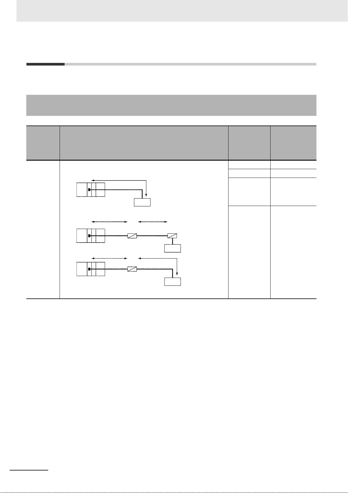
1 Introduction
1-5 System Configurations
This section explains the system configuration supported by each serial communications mode.
1-5-1 Protocol Macro, Serial Gateway, No-protocol, or Modbus-RTU
Slave
PLC:
Generalpurpose
external
device
1:1
Port:
RS-232C
Connection configuration Required
Connection of a Serial Communications Unit to a device with an
RS-232C or RS-422A/485 port.
*1
RS-232C
RS-232C
interface
*2*3
NT-AL001
RS-232C
Resistance ON
*3
RS-232C RS-422A/485
Resistance ON
RS-422A/485
*2
NT-AL001
Resistance
ON
NT-AL001
Resistance ON
5-V power
RS-232C
interface
RS-422A/485
interface
Connected
devices
serial
communica-
tions
port/Remarks
CJ1W-SCU22 P ort 1 or 2
CJ1W-SCU44 Port 2
NT-AL001 Con-
verting Link
Adapter
Converts
between RS232C and
RS-422A/485
5-V power supply
For NT-AL001
Link Adapter
1-10
*1 The maximum cable length for RS-232C is 15 m. The RS-232C specification does not define any use over 19.2
Kbps. Refer to the manual for the device being connected.
*2 The maximum total cable length for RS-422/485 is 500 m when an NT-AL001 Link Adapter is used. The length
includes branch lines. Communications distance may vary by the device being connected. Refer to the manual
for the device.
*3 The maximum length is restricted to 2 m when an NT-AL001 Link Adapter is connected.
CJ-series Serial Communications Units Operation Manual for NJ-series CPU Unit(W494)

1 Introduction
1-5 System Configurations
PLC:
General-
purpose
external
device
1:1
Port: RS -
422A/485
Connection configuration Required
devices
Connected
serial
communica-
tions
port/Remarks
Connection of a Serial Communications Unit to a device with an RS232C or RS-422A/485 port
*1
RS-422A/485 interface
Resistance ON
RS-232C
RS-232C interface
Resistance ON
Resistance ON
RS-422A/485
*1 *2
NT-AL001
RS-422A/
485
Resistance ON
5-V power
CJ1W-SCU32 Port 1 or 2
CJ1W-SCU42 P ort 1
NT-AL001 Con-
verting Link
Adapter
5-V power supply
Convert between
RS-232C and
RS-422A/485
For NT-AL001
Link Adapter
*1 With the CJ1W-SCU[]2, the maximum total cable length for RS-422/485 is 1200 m. The length when an NT-AL001
Link Adapter is used is 500 m. In both cases, the length incl udes branch lines. Communications distance may
vary by the device b ein g connecte d. Refer to the manual for the device.
*2 The maximum length is restricted to 2 m when an NT-AL001 Link Adapter is connected.
1
1-5-1 Protocol Macro, Serial Gateway, No-protocol, or Modbus-RTU Slave
CJ-series Serial Communications Units Operation Manual for NJ-series CPU Unit(W494)
1-11
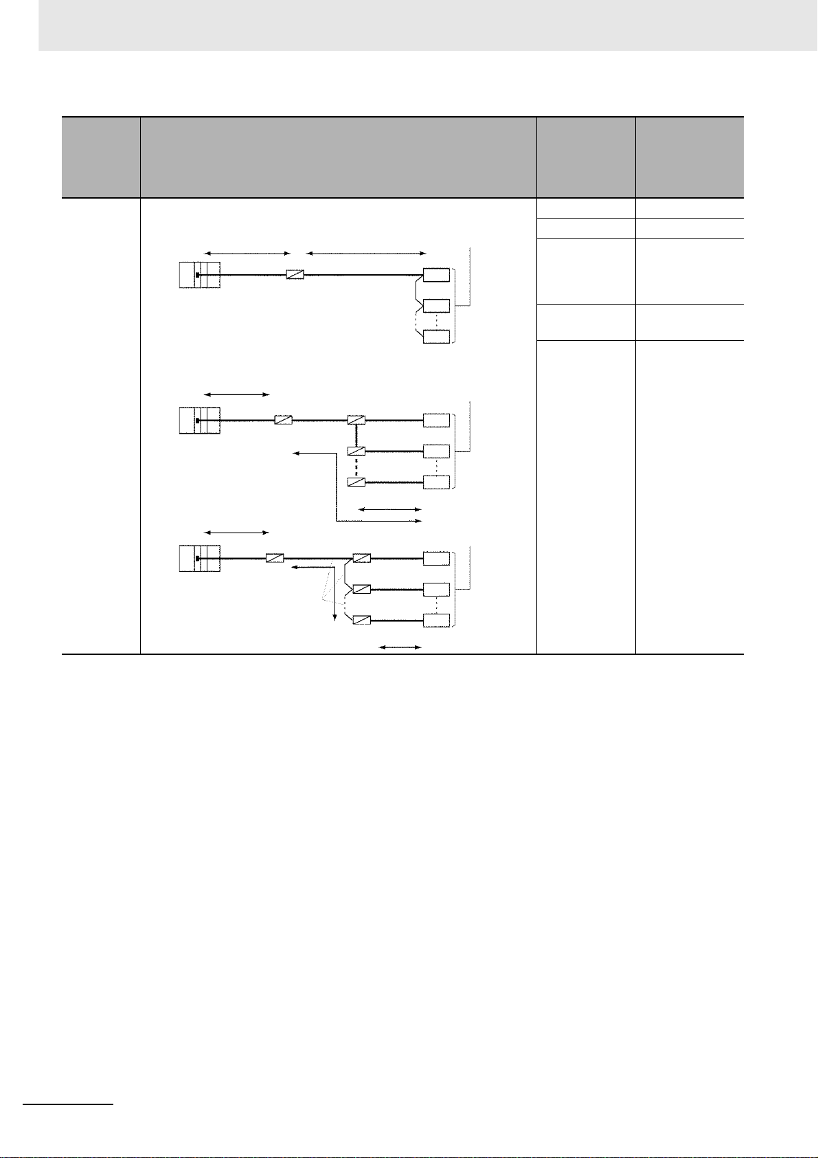
1 Introduction
PLC:
Generalpurpose
external
device
1:N
Port: RS -
232C
Connection configuration Required
Connection of a Serial Communications Unit to devices with
RS-232C or RS-422A/485 ports.
*2 *1
NT-AL001
RS-232C
Resistance ON
*2
NT-AL001
RS-232C
RS-422A/485
Resistance
ON
RS-422A/485
B500-AL001
*1
RS-422A/485 interface
Resistance ON
RS-422A/485 interface
Resistance ON
*3
Connected
devices
serial
communica-
tions
port/Remarks
CJ1W-SCU22 P ort 1 or 2
CJ1W-SCU42 Port 2
NT-AL001 Con-
verting Link
Adapter
Converts
between RS232C and
RS-422A/485
B500-AL001
Link Adapter
5-V power supply
For RS-422A/485
branching
For NT-AL001
Link Adapter
*2
RS-232C
NT-AL001
Resistance
ON
RS-422A/485
NT-AL001
*1
Resistance ON
5-V power
RS-232C
RS-232C
RS-232C
RS-232C interface
*2
*1 The maximum total cable length for RS-422/485 is 500 m when an NT-AL001 Link Adapter is used. The length
includes branch lines. Communications distance may vary by the device being connected. Refer to the manual
for the device.
*2 The maximum length is restricted to 2 m when an NT-AL001 Link Adapter is connected.
*3 The maximum branch line is 10 m.
1-12
CJ-series Serial Communications Units Operation Manual for NJ-series CPU Unit(W494)

1 Introduction
1-5 System Configurations
PLC:
General-
purpose
external
device
1:N
Port: RS -
422A/485
Connection configuration Required
Connection of a Serial Communications Unit to devices with RS-232C
or RS422A/485 ports
RS-422A/485 interface
Resistance ON
Resistance ON
RS-422A/485
*1
RS-422A/485
B500-AL001
*1
Resistance ON
RS-422A/485 interface
Resistance ON
*3
Connected
devices
serial
communica-
tions
port/Remarks
CJ1W-SCU32 Port 1 or 2
CJ1W-SCU42 P ort 1
NT-AL001 Con-
verting Link
Adapter
Converts
between RS232C and
RS-422A/485
B500-AL001
Link Adapter
5-V power supply
For RS-422A/485
branching
For NT-AL001
Link Adapter
1
1-5-1 Protocol Macro, Serial Gateway, No-protocol, or Modbus-RTU Slave
RS-232C interface
RS-232C
RS-232C
RS-232C
*2
Resistors ON
*1
RS-422A/485
Resistance ON
5-V power
NT-AL001
*1 The maximum total cable length for RS-422/485 is 500 m when an NT-AL001 Link Adapter is used. The length
includes branch lines. Communications distance may vary by the device being connected. Refer to the manual
for the device.
*2 The maximum length is restricted to 2 m when an NT-AL001 Link Adapter is connected.
*3 The maximum branch line is 10 m.
CJ-series Serial Communications Units Operation Manual for NJ-series CPU Unit(W494)
1-13

1 Introduction
1-6 Specifications
1-6-1 Serial Communications Unit
PLC Series CJ-series
Device name Serial Communications Unit
Classification CPU Bus Unit
Model number CJ1W-SCU22 CJ1W-SCU32 CJ1W-SCU42
Serial communica-
tions ports
Protocols Port 1 You can select Protocol Macro, Serial Gateway (*1), No-protocol, Modbus-
Number of mountable Units
Data exchange
with the CPU Unit
Supporting CPU Units NJ-series CPU Units
Current consumption (*2) 280 mA + x 400 mA 360 mA + x
Weight 160 g max. 120 g max. 140 g max.
Port 1 RS-232C RS-422A/485 RS-422A/485
Port 2 RS-232C RS-422A/485 RS-232C
Port 2
CPU Rack A total of up to 16 Units, including all other CPU Bus Units.
Expansion Rack
Ordinary
refreshing of software
switches and status
Transfer the System
Setting data from CPU
Unit
RTU Slave, or Loopback Test for each port.
No restrictions on the mounting location.
Data exchange with I/O port (constant data exchange with the CPU Unit)
Data exchange with I/O port
Data is transferred from the CPU Unit at the following times:
• When the Unit restarts or the Controller is reset, including when the
power is turned ON
• When the variable Settings Change
(_CJB_SCU@@P1ChgSta/_CJB_SCU@@P2ChgSta) changes to TRUE.
(@@ indicates Unit numbers.)
*1 The Serial Gateway can also be executed in Protocol Macro Mode.
*2 The current consumption is for one Serial Communications Unit.
When an NT-AL001 Link Adapter is connected to the Serial Communications Unit, power is supplied to the Link
Adapter from the Unit.
Add a current consumption of 150 mA for each Link Adapter that is connected.
The current consumption value varies by unit. Take a note of this when you replace a Unit.
In the above specifications, the mark "x" indicates additional 150 mA per RS-232C port to which an NT-AL001
Link Adapter is connected. A 5-V power is supplied from the port to the Adabor.
1-14
CJ-series Serial Communications Units Operation Manual for NJ-series CPU Unit(W494)

1 Introduction
1-6-2 General Specifications
The general specifications of the Serial Communications Units conform to those of the NJ-series CPU
Unit.
z Protocol Macro Function Specifications
Item Description
Number of protocols 20 max. Can be created and registered with the Protocol Support Tool
Number of sequences 1,000 max.
Per protocol Number of
sequences
Number of mes-
sages
Number of receive
matrixes
Sequence execution condition Using the CPU Unit's ExecPMCR instruction (specifying the sequence
Communications mode Half-duplex or full-duplex
Synchronous mode Start-stop synchronization (asynchronous mode)
Baud rate (*1) RS-232C port and RS-422A/485 ports:
Communications distance (*1) RS-232C port: 15 m max.
Connection configuration RS-232C port: 1:1 (1:N (N = 32 units max.) is possible using a Converting
Maximum number of
data exchange words
between PLC and protocol macro function
Sequence contents (step
common parameters)
Operand setting 250 words Including the word that specifies the number of
Link word setting 500 words O1, O2, I1, and I2: 500 words total
Direct setting 500 words Maximum number of words per data attribute
Number of steps
per sequence
Transmission con-
trol parameters (*2)
Response notifica-
tion method (operand)
Monitoring time
during send/receive
processing
Link word setting Area in which data is exchanged between the CPU Unit and the Serial
(CX-Protocol).
60 max.
300 max.
100 max.
number)
1,200/2,400/4,800/9,600/19,200/38,400/57,600/115,200/230,400 bps
Default setting: 9,600 bps
RS-422A/485 port:
1,200 m max. (total cable length: 1,200 m max., Multidrop connections are
possible. However, maximum cab le length is 500 m if the NT-AL001 is
used for RS-422A-485 connections.)
Link Adapter.)
RS-422A/485 port: 1:N (N = 32 units max.)
words (1 word)
16 max.
X-on/X-off flow, RS/CS flow, delimiter control, contention control or
modem control.
(Writes the receive data in the memory area used for CJ-series Units
specified in DstDat of the ExecPMCR instruction)
Writes the receive data to memory used for CJ-series Units during CPU
Unit I/O refresh.
Receive wait, receive completion, or send completion can be monitored.
Setting range: 0.01 to 0.99 s, 0.1 to 9.9 s, 1 to 99 s, or 1 to 99 minutes
Communications Unit during Communications Unit refreshing. Two areas
can be specified for each device: One for storing received data and the
other for storing sent data.
1-6 Specifications
1
1-6-2 General Specifications
CJ-series Serial Communications Units Operation Manual for NJ-series CPU Unit(W494)
1-15

1 Introduction
Item Description
Step contents Commands Send only (Send), receive only (Recv), send and receive (Send&Recv),
wait (Wait), reception buffer clear (Flush), ER-ON (Open), or ER-OFF
(Close)
Repeat counter 1 to 255 times
Retry count 0 to 9
(Only when the command is Send&Recv)
Send wait time 0.01 to 0.99 s, 0.1 to 9.9 s, 1 to 99 s, or 1 to 99 minutes
(Only when the command is Send or Send&Recv)
With or without
response write
(operand)
Next processing Select a process following to a normal end of a step from End (sequnece
Error processing Select a process following to an error end of a step from End, Next, Goto
Send message Data sent to the
Receive message Data sent from the
Receive matrix When the com-
Selectable either to store the received message when the receive process
completes or not. (This option is used to store received data to the area
specified by the DstDat of the ExecPMCR instruction.)
completed), Next (proceed to the next step No.), Goto (go to the specified
step No.), and Abort (interrupt the step and terminate the sequence.)
and Abort.
Consists of a header, address, length, data, error
specified address
when the command
is Send or
Send&Recv.
specified address
when the command
is Recv or
Send&Recv.
mand is Recv or
Send&Recv, sets
the expected
receive messages
(15 max.), and
switches the next
processing according to the message
received.
check code, and terminator.
For details, see the message unit contents on the
next page.
Specifies the receive messages and the next pro-
cessing for each of cases No. 00 to No. 15. One of
the maximum 16 cases must be set to "Other" in
the receive messages (i.e., other than the set
received messages).
1-16
CJ-series Serial Communications Units Operation Manual for NJ-series CPU Unit(W494)

1 Introduction
Message unit
contents
Item Description
Header and
terminator
data attributes
Data attributes
of addresses
and data in
send/receive
messages
Constant
Constant
Variable
ASCII data, hexadecimal data, or control code
ASCII data, hexadecimal data, or control code (For an address, control code is
not possible)
No conversion, conversion to ASCII data, or conversion to hexadecimal data
(the read/write direction can be specified)
Designation
method
X Word designa-
(X, Y)
X: Effective address (Location to read data from or to write data into)
Y: Data size (1 to 1,000) (*1)
Read word
tion
Wild card * Any data or address can be
Repeat counter N
(memory used
for CJ-series
Units to send
data)
Write word
(receive data to
memory used
for CJ-series
Units)
Specify by the
input variable:
SrcData of the
SendPMR
instruction.
Specify the
area using a
link word.
Directly specify the memory
used for CJseries Unit
Specify by the
in-out variable:
DstData of the
SendPMR
instruction.
Specify the
area by a link
word.
Memory for CJseries Unit
direct designation
received (only in receive messages)
Set leading
address + n
(The linear
expression aN
+ b, including
repeat counter
N, is also possible for n.)
1-6 Specifications
1
1-6-2 General Specifications
CJ-series Serial Communications Units Operation Manual for NJ-series CPU Unit(W494)
1-17

1 Introduction
Item Description
Message unit
contents
Trace function A total of up to 1,700 bytes (characters) of time-series data can be traced in
Data attributes
of addresses
and data in
send/receive
messages
Error check codes LRC, LRC2, CRC-CCITT, CRC-16, SUM, SUM1, and SUM2 can be calculated.
Maximum length of
send/receive messages
Maximum number of
data attributes registered in one message
Maximum number of
write data attributes
registered in one message
Variables
Y Linear expres -
sion including
repeat counter
Wild card * Can be received regardless of
Word designation
1,000 bytes. (A maximum length between 200 and 1,000 bytes can be set in the
Setup Area.)
96 attributes (*4)
30 attributes (*5)
send and receive messages.
Changes to the step No. and control signals such as RS and CS can also be
traced.
aN + b a: 0 to 1000; b: 1 to 1000
N: Repeat counter value
the length (only in receive messages)
Read word
(memory used
for CJ-series
Units to send
data)
Specify by the
input variable:
SrcData of the
SendPMR
instruction.
Specify the
area by a link
word.
Directly specify the memory
used for CJseries Unit
Set leading
address + n
(The linear
expression aN
+ b, including
repeat counter
N, is also possible for n.)
*1 The baud rate and the communications distance sometimes depend on the remote device. Confirm them in the
operation manuals for the connected devices.
*2 When you use 2-wire RS-422A/485 communications in Pr otoc ol Macro Mode, set only modem controls for the
transmission control parameters, and do not use RS/CS flow controls.
*3 The data size is the number of bytes on the transmission path.
*4 The CX-Protocol can be used to register up to 96 attributes per message.
*5 A macro syntax error will occur when th e protocol macro is executed if more than 31 write attributes are regis-
tered in one message.
1-18
CJ-series Serial Communications Units Operation Manual for NJ-series CPU Unit(W494)

1 Introduction
z Serial Gateway Specifications
Item Description
Conversion source Commands (received through network or CPU bus)
Conversion func-
tions
Converted format • CompoWay/F commands
Enabled serial communications mode
Queuing functions Up to five commands can be converted and then queued for processing.
Protocol macro exe-
cution processing
Response timeout
monitoring
Send start timeout
monitoring
Send delay The time can be set from when the message is converted into another protocol using
The received command is sent to the Unit's serial port and is converted to the command
code as follows:
2803 hex: Header removed and converted to CompoWay/F command.
2804 hex: Header removed and converted to Modbus-RTU command.
2805 hex: Header removed and converted to Modbus-ASCII command.
• Modbus-R TU commands
• Modbus-ASCII commands
Serial Gateway Mode or Protocol Macro Mode
When a command is received during protocol macro execution, the Serial Gateway is ex ecuted using an interrupt between steps in the communications sequence. If the next step
is a Receive command, the Serial Gateway will not be executed until the next step. For
other conditions, the interrupt is executed immediately. (*1)
The time is monitored from when the message converted into the specified protocol using
the Serial Gateway is sent until the response is received (in Serial Gateway Mode or Protocol Macro Mode). (*2)
Default: 5 s (setting range: 0.1 to 25.5 s)
The time is monitored from when the command is received until it is converted into the
specified protocol and starts to be sent (in Protocol Macro Mode only). (*3)
Default: 5 s (setting range: 0.1 to 25.5 s)
Serial Gateway conversion until the data is actually sent. (Serial Gateway or Protocol
Macro Mode)
Default: 0 s (setting range: 0.01 to 300.00 s)
1-6 Specifications
1
1-6-2 General Specifications
*1 The reception buffer is cleared during Serial Ga teway execution.
You can prohibit the Serial Gateway in Protocol Macro Mode by changing the Serial Gateway Prohibit Switch
(*_P#_SgwDsblCmd) to TRUE.
*2 When a ti meout occurs, a command end code (0205 hex (Response Timeout)) is retur ned to the command
source.
*3 When a timeout occurs, a command e nd code (0204 hex (Destination Busy)) is returned to the command
source. At this time, the received command is discarded without execution of send processing.
CJ-series Serial Communications Units Operation Manual for NJ-series CPU Unit(W494)
1-19

1 Introduction
z No-protocol Specifications
Communications
mode
Baud rate (*) RS-232C port and RS-422A/485 ports:
Communications
distance (*)
Messages (communications frame
structure)
Sending messages SerialSend instruction
Receiving mes-
sages
Maximum message
length
Data conversion No conversion
Communications
protocol
Message delay time When the SerialSend instruction is executed, after the send delay time, the data is sent
Receive counter The number of data bytes (0 to 256) received at the port can be counted.
Reception buffer
clear timing
Item Description
Full-duplex
1,200/2,400/4,800/9,600/19,200/38,400/57,600/115,200/230,400 bps
Default setting: 9,600 bps
RS-232C port: 15 m max.
RS-422A/485 port:
1,200 m max. (total cable length: 1,200 m max., Multidrop connections are possible. How-
ever, maximum cable length is 500 m if the NT-AL001 is used for RS-422A-485 connections.)
Set either of the following six types in the Sysmac Studio or device variable for CJ-series
Unit.
1. Data only (without start code or end code)
2. Start code + data
3. Data + end code
4. Start code + data + end code
5. Data + CR + LF
6. Start code + data +CR + LF
You can make the following setting with the Sysmac Studio or device variable f or CJ-series
Unit:
Select to have the start code or not,
select to have the end code or not,
select the start code from 00 to FF hex when you set to have one,
select the end code from 00 to FF hex when you set to have one, and
set the number of receive data bytes when you set not to have the end code.
Start code None or 00 to FF hex
End code None, 00 to FF hex, or CR + LF
Number of receive data bytes during recep-
tion
SerialRcv or SerialRcvNoClear instruction
Sending and receiving: Up to 259 bytes including the start code and end code (up to 256
bytes excluding start/end codes)
None
from the port.
0 to 300 s (0 to 300,000 ms)
(Can be set in 10-ms units: Set in System Studio or by using a device variable for CJ-series
Unit.)
SerialRcv instruction: After reading the receive data
SerialRcvNoClear instruction: When the receive data size variable (Size) is set to 0
Set the number of receive data bytes
between 1 and 256 bytes (according to the
settings in Sysmac Studio or device variable
for CJ-series Unit.) when frame structure 1
or 2 above is used.
1-20
* The baud rate and the communications distance sometimes depend on the remote device.
CJ-series Serial Communications Units Operation Manual for NJ-series CPU Unit(W494)

1 Introduction
z Modbus-RTU Specifications
Item Description
Mode Modbus-RTU Slave Mode (*)
Baud rate 1,200/2,400/4,800/9,600/19,200/38,400/57,600/115,200/230,400 bps
Default: 19,200 bps
Data length 8 bits
Parity Odd, even, or none
Default: Even
Stop bits Odd or even parity:1 bit
No parity: 2 bits
Address setting
range
Frame f ormat Slave address: 1 byte
* Modbus-ASCII Slave Mode is not supported.
1 to 247 (broadcasting: 0)
Function code: 1 byte
Data: 0 to 252 bytes
CRC code: 2 bytes
z Supported Commands
Function
code (hexa-
decimal)
01 Reads multiple bits from the CIO, Work, Holding, or Auxiliary Area of
memory used for CJ-series Units.
02 Reads multiple bits from the CIO Area of memory used for CJ-series
Units.
03 Reads multiple words from the DM or EM Area of memory used for
CJ-series Units.
04 Reads multiple words from the CIO, Work, Holding, or Auxiliary Area
of memory used for CJ-series Units.
05 Writes a bit in memory used for CJ-series Units. Write Single Coil
06 Writes a word in the DM or EM Area of memory used for CJ-series
Units.
08 Executes an echoback test. Diagnostic
0F Writes multiple bits in memory used for CJ-series Units. Write Multiple Coils
10 Writes multiple words in the DM or EM Area of memory used for CJ-
series Units.
Function Modbus name
Read Coils
Read Discrete Inputs
Read Holding Registers
Read Input Registers
Write Single Register
Write Multiple Registers
1-6 Specifications
1
1-6-2 General Specifications
CJ-series Serial Communications Units Operation Manual for NJ-series CPU Unit(W494)
1-21

1 Introduction
1-7 Selecting the Serial Communications
Mode
Connect Device
• Host computer
• OMRON
component
• Modbus-compatible device
(including
OMRON
components)
Creating
communications
frame for a host
computer protocol
Standard system
protocol
User-created
protocol
CompoWay/
F-compatible
Modbus-RTUcompatible
Modbus-ASCIIcompatible
Serial Communications Mode
Protocol macro
Modbus-RTU
Slave
Protocol macro
Protocol macro
Execute using ExecPMCR instruction.
Execute using SendCmd instruction.
Through network
Execute using SendCmd instruction.
Through network
Execute using SendCmd instruction.
Through network
Use a standard
system protocol.
Use the CX-Protocol to
change a standard
system protocol.
Modbus-RTU
commands
sent from host
Serial Gateway
Serial Gateway
Serial Gateway
Serial Gateway
Serial Gateway
Reference
• Section 4 Using
Protocol Macros
• CX-Protocol Operation
Manual (W344)
• Section 7 Using
Modbus-RTU Slave
Mode
• Section 5 Serial
Gateway
• Generalpurpose
external device
Protocol (including
no-protocol) used
mainly for stop-start
synchronous data
sending and reception
data in a single
direction from/to a
device such as a bar
code reader or printer
User-created protocol
using user program
Protocol macro
No-protocolSending/receiving
No-protocol
Use the CX-Protocol to
create a new protocol.
• Section 4 Using
Protocol Macros
• CX-Protocol Operation
Manual (W344)
• Section 6 No-protocol
Mode
1-22
CJ-series Serial Communications Units Operation Manual for NJ-series CPU Unit(W494)

1-8 Basic Operating Procedure
1-8-1 Overview
An overview of the basic operating procedures for the Serial Communications Unit is provided here.
There is no restriction regarding the sequence of "Programs and software settings" and "Hardware setting and rack assembly." These tasks may be carried out concurrently or in the reverse order.
1 Introduction
1-8 Basic Operating Procedure
1
Use Sysmac Studio to create and set programs.
For details on operations of Sysmac Studio, refer to the Sysmac S tudio NJ-One Version 1.0 Operation
Manual (Cat. No. W504).
·
Procedure 1
Procedure 2
Programming and software settings
Create POU and global
variables
Create Unit Configuration
Create Initialization Data
of the Unit
Set the unit numberProcedure 3
Install on RackProcedure 4
Create and register global variables and each POU.
· Create algorithm of each POU and register local variables of each POU.
·
Register the Unit in the Unit Configuration on the CPU/Expansion
Racks screen in Configuration and Setup.
·
At this time, set both the device name and the unit number of the
unit to be registered.
·
Allocate device variables for CJ-series Units to I/O ports.
Allocate on the I/O Map View window.
You can use one of the following three methods to allocate.
1. Select and allocate existing variables.
2. Input a new variable name.
3. Automatically create with "Create Device Variable."
·
Create the Unit settings by using the Edit Special Unit Settings.
·
Serial communications mode
·
Baud rate
·
Make the settings for the Transmission Mode for Protocol
Macro Mode (half-duplex or full-duplex), the maximum length of
send/receive data, etc.
(When the program is transferred, items set here will be reflected in the
device variable for CJ-series Unit (for initial setting).)
· Use the rotary switch on the front panel of the Unit to set the
unit number.
· Set the same unit number as in the Unit Configuration settings.
1-8-1 Overview
·
ConnectionProcedure 5
Procedure 6
Hardware setting and Rack assembly
Program transfer and operation
CJ-series Serial Communications Units Operation Manual for NJ-series CPU Unit(W494)
Turn ON the power to
the Controller
Transfer the user programProcedure 7
Reflect Unit settingProcedure 8
Main operationProcedure 9
Connect the Unit and external device(s), and the CPU Unit and
Sysmac Studio.
When an RS-422A/485 port is used, the following setting is required.
·
TERM: Terminating resistance ON/OFF switch
·
WIRE: 2-wire or 4-wire selector switch
· Reflect the settings for the switches on the front panel of the Unit,
in the Unit.
· Transfer user programs, Unit Configuration and Setup, and
variable information to the CPU Unit.
· Reflect the setting when one of the following events occurs.
· Controller reset
· At Unit restart
· Restart of communications port
·
Use the software switches and various flags of the Unit to perform serial
communications. The user program controls the Unit via I/O ports by
using device variables for CJ-series Unit.
1-23

1 Introduction
1-8-2 Explanation of Procedure
Procedure 1. Create POU, Global Variables and Unit Configuration
1
Create and register global variables and each POU.
2
Create algorithm for each POU and register local variables for each POU.
3
Register the Unit in the Unit Configuration on the CPU/Expansion Rac ks screen in Configurati on
and Setup.
Once this Unit is registered in the Unit Configur ation, I/O p orts are created automatically according to this Unit. Also set both the device name and the unit number of the unit to be registered.
4
Allocate device variables for CJ-series Unit to I/O ports.
Allocate on the I/O Map View window.
You can use one of the following three methods to allocate the device variables for CJ-series
Unit.
• Select and allocate existing variables.
• Input a new variable name.
• Automatically create with "Create Device Variable."
Procedure 2. Create Initialization Data of the Unit
Set the Initialization Data of the Unit, such as the Serial Comm unications Mode and communication s
specifications.
Set the initial settings on the Edit Special Unit Settings of Sysmac Studio.
1-24
CJ-series Serial Communications Units Operation Manual for NJ-series CPU Unit(W494)

Setting Example for Protocol Macro Mode
Example) Set the default (sta ndard) communications conditions
Set "Serial Communications Mode" to the Protocol Macro Mode.
1 Introduction
1-8 Basic Operating Procedure
1
1-8-2 Explanation of Procedure
Set "Maximum Number of Bytes in Protocol Macro Send/Receive Data" to 1000 bytes.
CJ-series Serial Communications Units Operation Manual for NJ-series CPU Unit(W494)
@
1-25
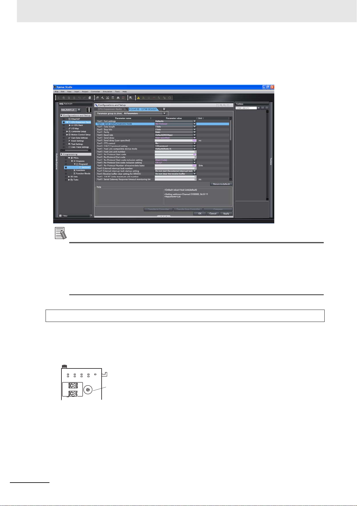
1 Introduction
Setting Example for No-protocol Mode
Example) Set the default (standard) communications conditions
Send delay is set to 100 ms, start code is included (e.g., @), end code is included (CR + LF), and
number of receive bytes is set to 100 bytes.
Additional Information
The Settings specified in the Spec ial Unit Setup Editing screen support all the functions of this
Unit. However, when used with NJ Series, some functions of this Unit become unavailable.
Please do not select functions that cannot be used. Errors will not be detected even if these functions are selected or set.
For functions that you cannot use with NJ series, refer to A-1 Differences in Available Functions
Depending on the CPU Unit (NJ or CJ Series).
Procedure 3. Set the Unit Number
Set the Unit number specific for each CPU Bus Unit mounted in a CPU Rack or Expansion Rack.
The Unit number must be the one registered in Unit Configurations. Set the unit number switch at
the top of the front panel to bet w e en 0 an d F. Turn OFF the Controller before changing the unit number setting.
CJ-series Units
SCU42
TERM
WIRE
OFF
RUN
RDY
2ON4
ERC
ERH
TER1
RD1
SD1
SD2
RD2
UNIT
5
4
6
3
7
8
9
A
NO.
B
Unit number switch
2
1
0
F
E
C
D
1-26
CJ-series Serial Communications Units Operation Manual for NJ-series CPU Unit(W494)

Procedure 4. Install on Rack
1
Align the connectors properly and then press in on the Unit to connect it.
2
Slide the sliders on the top and bottom of the Unit until they lock the Units together.
1 Introduction
1-8 Basic Operating Procedure
Connector
1
1-8-2 Explanation of Procedure
Move the sliders toward the back
until they lock into place.
Slider
Lock
Release
Precautions for Safe Use
If the sliders are not locked properly, the Serial Communications Units may not function correctly.
Procedure 5. Connection
Connect this Unit and the external devices using RS-232C or RS-422A/485 cables. Also, connect
the CPU Unit and Sysmac Studio. For details on the connector pin layout and the connection methods, refer to Section 3 Installation and Wiring, and refer to the relevant manuals for the external
devices to be connected.
z Types of Port for Different Models
The types of port for the different models of Serial Communication Units are shown in the following
table.
Model Port 1 Port 2
CJ1W-SCU22 RS-232C RS-232C
CJ1W-SCU32 RS-422A/485 RS-422A/485
CJ1W-SCU42 RS-422A/485 RS-232C
When an RS-422A/485 port is used in the Serial Communications Unit, the following setting is
required.
CJ-series Serial Communications Units Operation Manual for NJ-series CPU Unit(W494)
1-27

1 Introduction
• TERM:Terminating resistance ON/OFF switch
• WIRE: 2-wire or 4-wire selector switch
OFF: Terminating resistance OFF
ON: Terminating resistance ON
2: 2-wire; 4: 4-wire
OFF
2
Serial Communications Unit
RS-232C
RS-232C
NT-AL001
Terminating resistance
ON, 5-V power
supply required
ON
TERM
4
WIRE
NJ-series
RS-422A
/485
Serial Communications Unit
B500-AL001
RS-422A
/485
NJ-series
Terminating resistance
ON
Also perform other required processing, such as setting switches on the external device(s).
z Connection Example for Protocol Macro, Serial Gateway, No-protocol Mode,
and Modbus-RTU Slave Mode
Serial Communications
Unit
RS-232C
RS-422A/485
Terminating
resistance ON
General-purpose
external device
General-purpose
external device
General-purpose
external device
Terminating
resistance ON
General-purpose
external device
Also perform other required processing, such as setting switches on the external device(s).
1-28
CJ-series Serial Communications Units Operation Manual for NJ-series CPU Unit(W494)

1 Introduction
Procedure 6. Turn ON the Power Supply of Controller
Turn on the power supply of the Controller.
An I/O Setting Check Error occurs when there is a Unit Configuration in the CPU Unit which does
not match the actual Unit Configuration. In this case, restart the Controller in Procedure 8 to cancel
the error.
1-8 Basic Operating Procedure
Procedure 7. Transfer the User Program
Transfer user programs, Un it Configuration and Setup, and variable inf ormation from Sysmac Studio
to the CPU Unit.
At this time, special function setting data is not yet transferred in this Unit.
Procedure 8. Reflect Unit Settings
z Controller Reset
Reset the Controller. The System Settings specified in the Edit Special Unit Setting will be transferred from the CPU Unit to the Unit.
z Restarting
Restart the Unit by turning the restart bit in the system-defined var iable, from FALSE to TRUE. Or
restart the communications port by turning either Port 1 or 2 Setting Changing Flag to TRUE. Then
the System Settings are transferred.
• Restart Bits (** indicates unit numbers.)
System-defined
variable
_CJB_CBU**Restart BOOL RW CPU Bus Unit Restart
Type R/W Name Function
TRUE: CPU Bus Units are restarted.
Bits
FALSE: CPU Bus Units are not restarted.
Default: FALSE
1
1-8-2 Explanation of Procedure
• Port 1/2 Settings Changing Flag (** indicates unit numbers.)
System-defined
variable
_CJB_SCU**P1ChgSta BOOL RW Serial Communica-
_CJB_SCU**P2ChgSta BOOL RW Serial Communica-
Type R/W Name Function
TRUE: Port 1 Serial Communications Port
tions Unit ** Port 1 Settings Changing Flag
tions Unit ** Port 2 Settings Changing Flag
Settings will change or are changing.
FALSE: All other statuses
Default: FALSE
TRUE: Port 2 Serial Communications Port
Settings will change or are changing.
FALSE: All other statuses
Default: FALSE
Procedure 9. Main operation
Execute the communications in Serial Communications Mode as set. The user program controls the
Unit by using the device variables for CJ-series Unit allocated to the I/O ports corresponding to software switches and various flags.
CJ-series Serial Communications Units Operation Manual for NJ-series CPU Unit(W494)
1-29
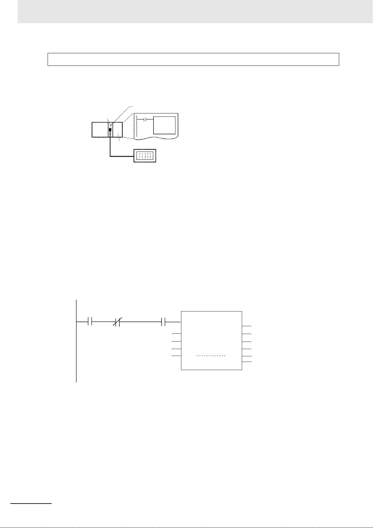
1 Introduction
Protocol Macros
When a standard system protocol (provided in the Serial Communications Unit, and CX-Protocol) is
executed
Using Standard System Protocols
Uses standard system protocol No. 600
Unit
ExecPMCR
CPU Unit
1
Creating the User-defined Variable to Store Send/Receive Data
External device
Example: K3N Series
Digital Panel Meter
Create a word-type array variable to be set as the input parameter in input variable SrcDat, and
in-out variable DstDat, of the ExecPMCR instruction. Reserve the number of array elements
(size) that are required.
2
Setting the Send Data
Refer to Send Data Allocation in R-1-1 Using Standard Syst em Protocols and set the number of
send data words to the starting element of SrcDat and the send data to the second and subsequent elements.
3
Coding ExecPMCR Instruction
Example) The following example shows how to use a Serial Communications Unit to read and
store the present values of E5@N Temperature Cont roller by using the CompoWay/F Master
standard system protocol sequence No. 610: Variable Area Read.
Input
condition
Protocol Macro
Executing Flag
*_P2_PmrExecSta
Network Communications
Instruction Enabled Flag
_Port_isAvailable
InPort Port
UINT#610 SeqNo
SendData[0] SrcDat
RecvData[0]
ExecPMCR_instance
Execute
DstDat DstDat
ExecPMCR
Done
Busy
Error
ErrorID
ErrorIDEx
1-30
If the Input condition is TRUE when the Protocol Macro Executing Flag (*_P2_PmrExecSta) is
FALSE and the Network Communications Instruction Enab le d Flag (_Port_isAvailable) is TRUE,
communications sequence No. 610 of the standard system protocol in the Serial Communications Unit is called, and data is sent and received via port 2 of the Serial Communications Unit.
For the details of the above example, refer to Section 4-3-2 User Program Example.
CJ-series Serial Communications Units Operation Manual for NJ-series CPU Unit(W494)

4
Executing the ExecPMCR Instruction
5
Confirming Operation
Refer to CX-Protocol Ver.1.9 OPERATION MANUAL (Cat. No. W344).
• Transmission Line Tracing
The data in the send/receive messages flowing over the transmission line (RS-232C or RS422A/485) and the control codes are traced.
• I/O Memory Monitoring
Monitors send/receive data and the status of the various flags.
Executing User-defined Protocols
CX-Protocol
Use the CX-Protocol to create
protocols.
Unit
ExecPMCR
1 Introduction
1-8 Basic Operating Procedure
1
1-8-2 Explanation of Procedure
CPU Unit
External device
CJ-series Serial Communications Units Operation Manual for NJ-series CPU Unit(W494)
1-31

1 Introduction
1
Designing Protocols
Refer to Section 4 and Section 5 in the CX-Protocol Ver.1.9 OPERATION MANUAL (Cat. No.
W344) for details.
a. Create a communications sequence status transition chart.
b. From the status transition chart, divide the processing contents into a sequence and steps.
c. Determine the communications sequence message contents .
2
Creating and Transferring the Project (protocol data) on CX-Protocol.
Refer to Section 1-10 of CX-Protocol Ver.1.9 OPERATION MANUAL (Cat. No. W344) for the
outline of the flow.
a. Creating a new project:
Refer to 6-1 Creating a New Project and Protocol in the CX-Protocol Ver.1.9 OPERATION MAN-
UAL (Cat. No. W344).
b. Creating a new communications sequen ce:
Refer to 7-1 Creating a New Sequence and 7-2 Setting a Sequence in the CX-Protocol Ver.1.9
OPERATION MANUAL (Cat. No. W344).
c. Creating steps:
Refer to 8-1 Creating a New Step and 8-2 Setting a Step in the CX-Protocol Ver.1.9 OPERA-
TION MANUAL (Cat. No. W344).
d. Creating messages:
Refer to 9-2 Setting a Message in the CX-Protocol Ver.1.9 OPERATION MANUAL (Cat. No.
W344).
e. Transferring the created project to a Unit:
Refer to 11-1 Transferring and Reading Protocol Data between the Personal Computers and
Serial Communications Board and Unit in the CX-Protocol Ver.1.9 OPERATIO N MANUAL (Cat.
No. W344).
After creating messages, steps can also be created by specifying message names.
3
Creating the User Program.
a. Creating User-defined Variables for Send/Receive Data Area
Create a word-type array variable to be set as the input parameter in input variable SrcDat
(Send Data Area) and in-out va riable DstDat (Receive Data Area) of the ExecPMCR instruction.
Reserve the number of array elements (size) that are required.
b. Setting Send Data
• Specifying Operands
Set the send data to the second and subsequent elements of user-defined variable SendData
of the input parameter set up in input variable of the ExecPMCR instruction, SrcDat. Set the
number of send data words to the starting element of SendData.
• Direct Designations
Set the send data in the memory used for CJ-series Units specified by the read variables in
the send message.
• Specifying Link Words
Set the send data in the O1 or O2 area of the Link Word Area.
c. Coding ExecPMCR Instruction
1-32
CJ-series Serial Communications Units Operation Manual for NJ-series CPU Unit(W494)

1 Introduction
)
1-8 Basic Operating Procedure
Input
condition
Protocol Macro
Executing Flag
*_P2_PmrExecSta
Network Communications
Instruction Enabled Flag
_Port_isAvailable
InPort Port
UINT#100 SeqNo
SendData[0] SrcDat
RecvData[0]
ExecPMCR_instance
ExecPMCR
Execute
DstDat
Done
Busy
Error
ErrorID
DstDat
ErrorIDEx
If the Input condition is TRUE when the Protocol Macro Executing Flag (*_P2_PmrExecSta for
port 2) is FALSE and the Ne twork Communications Instruction Enabled Flag (_Port_isAvailable)
is TRUE, communications sequence No. 100 registered in the Serial Communications Unit is
called, and data is sent and received via port 2 of the Serial Communications Unit.
Send data is sent star ting from the second element of the SendData and its size (number of
words) is specified by the first element of "SendData".
SendData[0]:
SendData[1]:
Number of words
Send data
Size of effective words (including SendData[0]
Number of words
The receive data is stored in consecutive words beginning with input parameter "RecvData[1]",
and the number of words actually stored in the input parameter is stored in "RecvData[0]".
1
1-8-2 Explanation of Procedure
RecvData[0]:
RecvData[1]:
Number of words
Receive data
Size of effective words (including RecvData[0])
Number of words
d. Executing the ExecPMCR I nst ruction
4
Confirming operation. Refer to Section 12 Tracing and I/O Memory Monitoring in the CX-Proto-
col Ver.1.9 OPERATION MANUAL (Cat. No. W344).
• Transmission Line Tracing
The data in the send/receive messages flowing over the transmission line (RS-232C or RS422A/485) and the control codes are traced.
• I/O Memory Monitoring
Monitors send/receive data and the status of the various flags.
z Serial Gateway Mode
• Sending commands from the Controller
Send commands by using the SendCmd instruction. For details, refer to 5-6 Communications
Frames.
• Sending commands from the PT
Execute the PT's SAP (Smart Active Parts).
CJ-series Serial Communications Units Operation Manual for NJ-series CPU Unit(W494)
1-33

1 Introduction
z No-protocol Mode
Creating the User Program
Execute the SerialSend instruction to send the program to the external device from the Controller.
For the SerialSend instruction, include an N.O. of the Network Communications Instruction Enabled
Flag (_Port_isAvailable) and an N.C. of the SerialSend Executing Flag
(*_P1_NopSerialSendExecSta/*_P2_NopSerialSendExecSta) in an AND condition as the input con-
dition.
Execute the SerialRcv or SerialRcvNoClear instr uction to receive data at the Controller from the
external device.
Include an N.O. input for the Reception Completed Flag (*_P1_NopRcvCompleteSta or
*_P2_NopRcvCompleteSta) and an N.O. input of the Network Communications Instruction Enabled
Flag (_Port_isAvailable) in an AND condition as the input condition to the SerialRcv or SerialRcvNo-
Clear instruction.
z Modbus-RTU Slave Mode
Modbus-RTU commands are sent from the host computer to the controller.
Programming to
send commands
and receive
responses.
Host computer
Serial Communications Unit
Command
The host computer must be programmed to send the Modbus-RTU commands and receive
responses.
1-34
CJ-series Serial Communications Units Operation Manual for NJ-series CPU Unit(W494)

Initial Settings and Allocations of
Device Variable for CJ-series Unit
This section describes the components of the Serial Communications Bo ards and the
Serial Communications Units, the settings requ ired for operation, and the memory allocated in the I/O memory of the CPU Unit to control and monitor communications.
2-1 Component Names and Functions . . . . . . . . . . . . . . . . . . . . . . . . . . . . . . . . 2-2
2-2 Data Exchange with the CPU Unit . . . . . . . . . . . . . . . . . . . . . . . . . . . . . . . . 2-8
2-2-1 Data Flow . . . . . . . . . . . . . . . . . . . . . . . . . . . . . . . . . . . . . . . . . . . . . . . . . . . . . 2-8
2-2-2 How to Specify and Create Variables . . . . . . . . . . . . . . . . . . . . . . . . . . . . . . 2-12
2-3 Device Variable for CJ-series Unit . . . . . . . . . . . . . . . . . . . . . . . . . . . . . . . 2-14
2-3-1 Allocations of Device Variable for CJ-series Unit . . . . . . . . . . . . . . . . . . . . . . 2-14
2-3-2 Device Variable for CJ-series Unit for System Settings . . . . . . . . . . . . . . . . . 2-14
2-3-3 Device Variable for CJ-series Unit for Software Switches . . . . . . . . . . . . . . . 2-23
2-3-4 Device Variable for CJ-series Unit for Status . . . . . . . . . . . . . . . . . . . . . . . . . 2-24
2-4 System-defined Variable . . . . . . . . . . . . . . . . . . . . . . . . . . . . . . . . . . . . . . . 2-34
2
CJ-series Serial Communications Units Operation Manual for NJ-series CPU Unit(W494)
2-1

2 Initial Settings and Allocations of Device Variable for CJ-series Unit
2-1 Component Names and Functions
CJ-series Serial Communications Unit
CJ1W-SCU22
SCU22
RUN
ERC
RD1
SD1
SD2
RD2
ERH
RDY
4
3
2
1
0
F
E
D
PORT1
PORT2
CJ1W-SCU32
SCU32
RUN
ERC
RD1
SD1
SD2
RD2
ERH
RDY
TERM
WIRE
OFF
2ON4
RDARDA+
SDASDA+
FG
RDARDA+
SDASDA+
FG
4
3
2
1
0
F
E
D
PORT1
(RS422
/485)
PORT2
(RS422
/485)
TERM
WIRE
5
6
7
B
C
5
6
7
B
C
OFF
UNIT
8
9
A
NO.
TER1
TER2
UNIT
8
9
A
NO.
2ON4
Indicators
Unit number
switch
Port 1:
RS-232C
Port 2:
RS-232C
Indicators
Terminating
resistance
switch (for port 1)
Unit number
switch
2-wire/4-wire
switch
(for port 1)
Port 1:
RS-422A/485
terminal-block
connector
Port 2:
RS-422A/485
terminal-block
connector
CJ1W-SCU42
SCU42
RUN
ERC
RD1
SD1
SD2
RD2
ERH
RDY
TERM
WIRE
OFF
2ON4
RDARDA+
SDASDA+
FG
5
4
3
2
1
0
F
E
D
PORT1
(RS422
/485)
PORT2
Bottom view
TER1
UNIT
6
7
8
9
A
NO.
B
C
Indicators
Terminating
resistance switch
Unit number
switch
2-wire/4-wire
switch
Port 1:
RS-422A/485
terminal-block
connector
Port 2:
RS-232C
Terminating resistance
switch (for port 2)
2-wire/4-wire switch
(for port 2)
2-2
CJ-series Serial Communications Units Operation Manual for NJ-series CPU Unit(W494)

2 Initial Settings and Allocations of Device Variable for CJ-series Unit
z Indicators
Indicator Color Status Meaning
RUN Green Lit Operating normally.
Not lit Unit hardware error.
RDY Green Lit Protocol macro preparations are complete.
Flashing Protocol macros are being prepared. (*1)
Not lit Hardware error in Serial Communications Unit.
ERH Red Lit CPU Unit error or this Unit was not registered in the Unit Configuration.
Routing tables incorrectly registered in the Unit.
Flashing System Setup Error. (*2).
Not lit CPU Unit is operating normally and the system settings are normal.
ERC Red Lit Unit Hardware Error.
Flashing Protocol data syntax error or protocol data error (SUM error).
Not lit Unit is operating normally.
SD1 Yellow Lit Communications port 1 is being used for sending.
Not lit Communications port 1 is not being used for sending.
RD1 Yellow Lit Communications port 1 is being used for receiving.
Not lit Communications port 1 is not being used for receiving.
TER1 (*3) Yellow Lit Terminating resistance is connected internally for communications port 1.
Not lit Terminating resistance is not connected internally for communications
port 1.
SD2 Yellow Lit Communications port 2 is being used for sending.
Not lit Communications port 2 is not being used for sending.
RD2 Yellow Lit Communications port 2 is being used for receiving.
Not lit Communications port 2 is not being used for receiving.
TER2 (*4) Yellow Lit Terminating resistance switch for Port 2 is ON.
Not lit Terminating resistance for Port 2 is OFF.
2-1 Component Names and Functions
2
*1 Depending on the interval of flashing, the meaning is as follows:
Protocol data being initialized: 0.3 s
Protocol data initialized, or being overwritten: 1.0 s
Protocol data error: 1.0 s and CPU Unit ERC indicator is flashing
*2 System settings use the device variables for CJ-series Unit determined by the unit number setting. For details,
refer to 2-3-2 Device Variable for CJ-series Unit for System Settings.
*3 Only the CJ1W-SCU32/SCU42 are equipped with a TER1 indicator.
*4 Only the CJ1W-SCU32 is equipped with a TER2 indicator.
For actions required when an error occurs, refer to Section 9 Troubleshooting and Maintenance.
z Unit No. Switch [UNIT No.]
Set the CPU Bus Unit unit number for the Unit. Set the Unit number specific for each CPU Bus Unit
mounted in a CPU Rack or Expansion Rack. The Unit number must be the one registered in Unit
Configurations. Set the unit number bet w een 0 and F.
The factory setting is for unit number 0. Turn OFF the Controller before changing the unit number setting.
CJ-series Serial Communications Units Operation Manual for NJ-series CPU Unit(W494)
2-3

2 Initial Settings and Allocations of Device Variable for CJ-series Unit
z RS-232C P orts
Protocol Protocol macro
Communications
method
Synchronization Start-stop synchronization (asynchronous)
Baud rate
Connections 1:1 (1:N is possible with Link Adapters)
Transmission
distance
Interface Complies with EIA RS-232C
Full-duplex or half-duplex
1200/2400/4800/9600/19200/38400/57600/
115200/230400 bps
15 m max. (*)
Protocol
Communications
method
Synchronous mode --- --- --Baud rate 1200/2400/4800/9600/19200/38400/57600/115200/230400 bps
Connection
configuration
Communications
distance
Interface Complies with EIA RS-232C
* The maximum cable length for RS-232C is 15 m. The RS-232C standard, however, does not cover baud rates
above 19.2 Kbps. Refer to the manual for the device to be connected to confirm support.
No-proto-
col
Full-duplex --- ---
1:1 (1:N is possible with Link Adapters)
15 m max. (*)
Serial Gateway Modbus-RTU
Connector Pin Layout
Pin No.
1 (*1) FG Shield --2 SD Send data Output
3 RD Receive data Input
4 (*2) RS Requ est to send Output
5 (*2) CS Clea r to send Input
6 (*3) 5V Power supply --7 (*2) DR Data set ready (*4) Input
8 (*2) ER Data terminal ready Output
9 SG Signal ground --Shell (*1) FG Shield ---
Abbrevia-
tion
Signal name I/O
9
6
5
1
2-4
*1 Pin No. 1 and the shell are connected to the ground terminal (GR) of the Power Supply Unit inside of the Serial
Communications Unit. Therefore, ground the GR of the Power Supply Unit to ground the cable shield.
*2 You can monitor the status of the RS, CS, DR, and ER signals by using the device variables for CJ-series Unit.
For details, refer to 2-3-4 Device Variable for CJ-series Unit for Status. You can use the DR signal for any pur-
pose specified by the user since it does not affect the system operations.
*3 Pin 6 (5 V) is required when the NT-AL001 Link Adapter is connected. For details on connection methods, refer
to 3-2 Wiring.
*4 The DR signal is used to monitor the signal cable. You can also use it as a CD (carrier detection) signal.
CJ-series Serial Communications Units Operation Manual for NJ-series CPU Unit(W494)

2 Initial Settings and Allocations of Device Variable for CJ-series Unit
Precautions for Safe Use
Do not connect the Pin 6 (+5-V power supply) of the RS-232C port on the Unit to any external
device other than an NT-AL001 Link Adapter. O therwise , t he e x ternal de vice and the Serial Co mmunications Unit may be damage d.
Use the OMRON Cables specified in this man ual or make your own cab l es. Do not use commercially available RS-232C cables sold for personal computers. Otherwise, the external device and
the Serial Communications Unit may be damaged.
The following cables are provided for connection to NT-AL001 Link Adapters. We recommend that
you use these cables.
NT-AL001 connecting cables:
XW2Z-070T-1 (0.7 m)
XW2Z-200T-1 (2 m)
Applicable Connectors
Plug: XM2A-0901 (manufactured by OMRON) or equivalent
Hood: XM2S-0911-E (manufactured by OMRON) or equivalent
One plug and one hood are provided for each port.
Recommended Cables
UL2464 AWG28 × 5P IFS-RVV-SB
AWG28 × 5P IFVV-SB
2-1 Component Names and Functions
2
UL2464-SB (MA) 5P × 28AWG (7/0.127)
CO-MA-VV-SB 5P × 28AWG (7/0.127)
Cable length: 15 m max.
z RS-422A/485 Port
Protocol
Communications
method
Synchronous mode Start-stop synchronizatio n (asynchronous mode)
Baud rate
Connection
configuration
Communications
distance
Interface Complies with EIA RS-485
Protocol
Communications
method
Synchronous mode --- --- --Baud rate 1200/2400/4800/9600/19200/38400/57600/115200/230400 bps
Connection
configuration
Communications
distance
Interface Complies with EIA RS-485
Full-duplex or half-duplex
1200/2400/4800/9600/
19200/38400/57600/115200/230400 bps
1:N (N: 32 Units max.)
500 m max. (The total combined cable length is 500m
max. T-branch lines must be a maximum of 10m long.)
No-proto-
col
Full-duplex --- ---
1:N (N: 32 Units max.)
500 m max. (The total combined cable length is 500m max. T-branch lines must be a
maximum of 10m long.)
Protocol macro
Serial Gateway Modbus-RTU
CJ-series Serial Communications Units Operation Manual for NJ-series CPU Unit(W494)
2-5

2 Initial Settings and Allocations of Device Variable for CJ-series Unit
Connector Pin Layout
Pin No.
1 (*1) RDA Receive data - Input
2 (*1) RDB Receive data + Input
3 (*1) SDA Send data - Output
4 (*1) SDB Send data + Output
5 (*2) FG Shield ---
*1 For 2-wire connections, use either pins 1 and 2 or pins 3 and 4.
*2 Pin 5 (the shield) is connected to the GR terminal on the Power Supply Unit though the Serial Communications
Unit. The Cable Shield can thus be grounded if you ground the GR terminal of the Power Supply Unit.
Precautions for Safe Use
The signal names SDA/B and RDA/B do not always have the sam e polarity as that sh o wn above.
Check the polarity of the external device before you make connections.
Abbrevia-
tion
Signal name I/O
1
2
3
4
5
Applicable Connectors
Plug:FMC 1.5/5-STF-3.5AU (screwless model by Phoenix Contact) or equivalent
MC1.5/5-STF-3.5AU (model with screw terminals by Phoenix Contact) or equivalent
Recommended Cables
CO-HC-ESV-3P × 7/0.2 (by Hirakawa Hewtech Corp.)
Cable length: 1,200 m max. (multidrop connections)
z Terminating Resistance Switch [TERM]
When an RS-422/485 port is used, set the switch to ON if the Serial Communications Unit is on the
end of the transmission line. Refer to Section 3 Installation and Wiring for the ON/OFF settings.
Label Name Settings Factory setting
TERM Terminating resis-
tance switch
Note You can monitor the status of the ter minatin g resistance setting with the device variables for CJ-series Unit.
For details, ref e r to 2-3-4 Device Variable for CJ-series Unit for Status.
ON: Term inating resistance ON
OFF: Ter m inating resistance OFF
OFF: Terminating resistance OFF
z 2-wire or 4-wire Switch [WIRE]
When an RS-422A/485 port is used, set the switch to "2" when 2-wire connectio ns are used, and set
the switch to "4" when 4-wire connections are used.
For details, refer to Section 3 Installation and Wiring.
2-6
Label Name Settings Factory setting
WIRE 2-wire or 4-wire switch 2: 2-wire
4: 4-wire
CJ-series Serial Communications Units Operation Manual for NJ-series CPU Unit(W494)
2: 2-wire
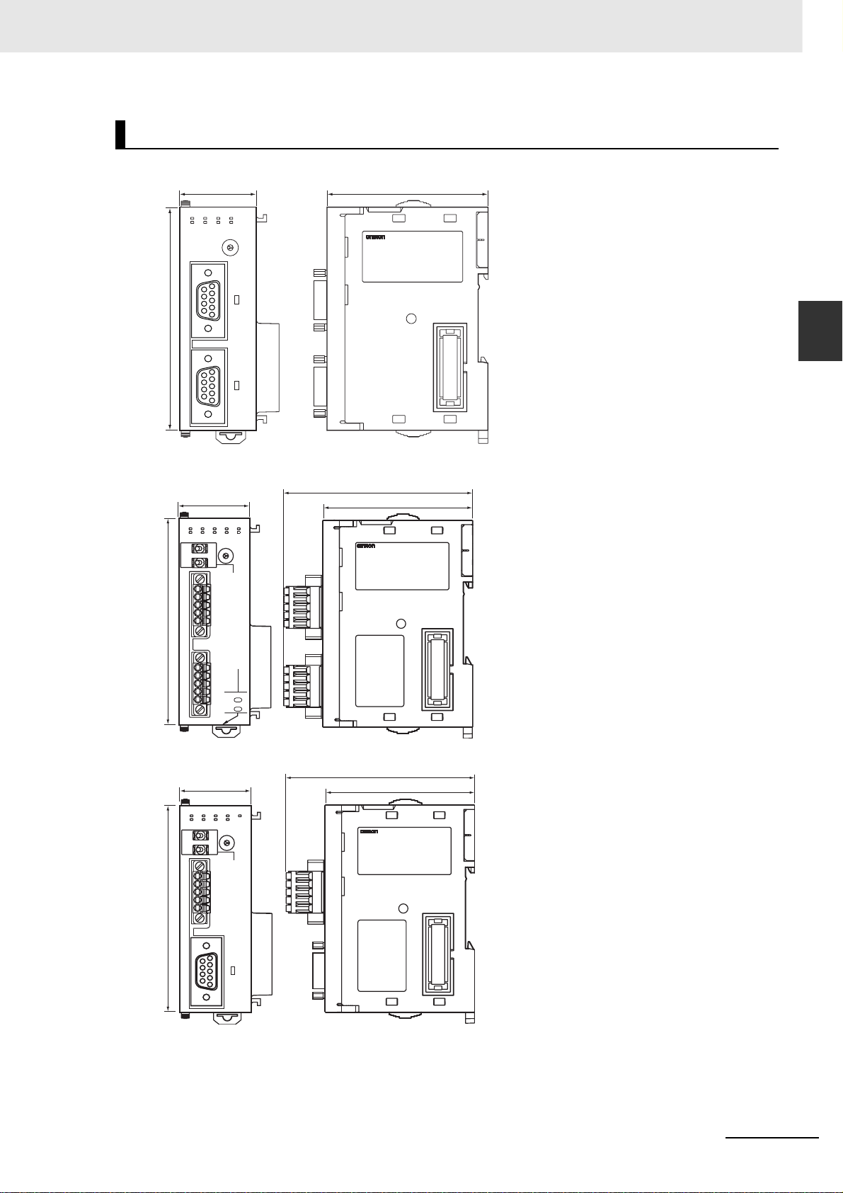
2 Initial Settings and Allocations of Device Variable for CJ-series Unit
Dimensions (Unit: mm)
CJ1W-SCU22
31 65
SCU22
RUN
ERC
RD1
SD1
SD2
RD2
ERH
RDY
UNIT
5
4
6
3
7
2
8
1
9
0
A
NO.
F
B
E
C
D
PORT1
90
PORT2
2-1 Component Names and Functions
2
CJ1W-SCU32
31
SCU32
RUN
ERC
RD1
SD1
SD2
RD2
ERH
RDY
TERM
WIRE
90
OFF
2ON4
RDARDA+
SDASDA+
FG
RDARDA+
SDASDA+
FG
3
2
1
0
F
E
5
4
6
7
8
9
A
B
C
D
PORT1
(RS422
/485)
PORT2
(RS422
/485)
TERM
OFF
WIRE
2ON4
CJ1W-SCU42
31
SCU42
RUN
ERC
RD1
SD1
SD2
RD2
ERH
RDY
TERM
OFF
WIRE
90
2ON4
RDARDB+
SDASDB+
FG
4
3
2
1
0
F
E
D
PORT1
5
6
7
8
9
A
B
C
(RS422
/485)
TER1
TER2
UNIT
NO.
TER1
UNIT
NO.
81.9
65
81.9
65
PORT2
CJ-series Serial Communications Units Operation Manual for NJ-series CPU Unit(W494)
2-7

2 Initial Settings and Allocations of Device Variable for CJ-series Unit
2-2 Data Exchange with the CPU Unit
Data exchange betw een th is Unit and the CPU Unit s uses the I/ O port allocated to the Serial Communications Unit or memory used for CJ-series Unit, if necessary.
For details on I/O ports, refer to 2-3 Device Variable for CJ-series Unit.
2-2-1 Data Flow
The CPU Unit and Serial Communications Unit exchange data as shown in the table and figure below.
Data exchange type
Access methods from
the user program
Device variable for CJseries Unit
User-defined variable Memory used for CJ-
System-defined variable --- During I/O refresh Send/receive data of Serial Port I/O
AT specification
destination
I/O port (for Operation Data)
I/O port (for System
Settings data)
series Unit
Data exchange timing Unit data type
During I/O refresh Software switch
Status
When the power is
turned ON, the serial
communications port
setting is changed, or
the Unit is restarted
During I/O refresh Data in holding registers and other
At I/O refresh immediately after instruction
execution
System Settings data
allocation areas in the ModbusRTU Slave Mode
Send/receive data of Serial Communications instructions, etc.
instructions, etc.
2-8
CJ-series Serial Communications Units Operation Manual for NJ-series CPU Unit(W494)

2 Initial Settings and Allocations of Device Variable for CJ-series Unit
2-2 Data Exchange with the CPU Unit
User program
For input
Device variable for
CJ-series Unit
For output
Device variable for
CJ-series Unit
For System Setting
Device variable for
CJ-series Unit
NJ-series CPU Unit
AT specification
AT specification
AT specification
I/O port
Operation Data
Status (for port 1)
Status (for port 2)
Software switch (for port 1)
Software switch (for port 2)
System Settings data
Setup Area (for port 1)
Setup Area (for port 2)
Memory used for CJ-series Unit
I/O refresh
I/O refresh
Update (*)
Serial Communications Unit
Status and
software
switch data
for each
communications
port
2
2-2-1 Data Flow
System Setup
data for each
communications
port
User-defined
variable
System-defined Variable
Serial Communications Port
Settings Change Bits
CPU Bus Unit
Restart Bits
AT specification
Send/receive data
Instruction
During execution of the instruction
Send data
Receive data
* This is executed when the Controller is reset, the serial communications port setting is changed, or the Uni t is
restarted.
CJ-series Serial Communications Units Operation Manual for NJ-series CPU Unit(W494)
2-9

2 Initial Settings and Allocations of Device Variable for CJ-series Unit
Device variable for CJ-series Unit
Device variables for CJ-series Units are variables for which AT is specified for the I/O port explained
below.
The user program uses device variables for CJ-series Unit to access the Configuration Unit such as
Serial Communications Unit.
For allocation of the device variables for CJ-series Unit to the I/O por t, refer to How to Create User-
defined Variables (P. 2-13).
z I/O port
An "I/O port" is a logical interface for data exchange by a CPU Unit with a Serial Communications
Unit or other Configuration Unit.
An I/O port has a unique pre-defined name for each unit model and function.
An I/O port is automatically created by preparing the Unit Configuration with Sysmac Studio.
For the details of I/O ports defined for the Serial Communications Unit, refer to 2-3 Device Variable
for CJ-series Unit.
There are two types of I/O ports for the Serial Communications Unit: those for Operation Data and
those for System Settings data.
z Operation Data
• Software Switch for Each Communications Port
Software switch data to be output (from CPU Unit to this Unit) exists for each communications
port.
Software switch data is stored at the I/O ports for Operation Data allocated for the Serial Communications Unit.
The user program references data and operates switches via the device variable for CJ-series
Unit.
Data is updated during I/O refreshing.
• Status of Each Communications Port
Status data to be input (from this Unit to CPU Unit) exists for each communications port. Status
data is stored at the I/O ports for Operation Data allocated for the Serial Communications Unit.
The user program references data via the device variable for CJ-series Unit.
Data is updated during I/O refreshing.
z System Settings data
• System Settings Data for Each Communications Port
System Settings data exists for each communications port.
Configure the System Settings data using the Edit Special Unit Settings view of Sysmac Studio.
You can also configure System Settings by using th e device variables for CJ-series Unit (for system setting) that are AT spec ifie d to th e ap plic able I/O ports from the user program.
System Settings data is stored at the I/O ports for System Settings data allocated for the Serial
Communications Unit. System Settings data will be retained by the battery even during power
interruptions.
The data is transferred to the Serial Communications Unit and updated when the Controller is
reset, the serial communications po rt setting is changed, or the Unit is restarted.
2-10
CJ-series Serial Communications Units Operation Manual for NJ-series CPU Unit(W494)

2 Initial Settings and Allocations of Device Variable for CJ-series Unit
User-defined variab le
The user program uses user-defined va riables to access the storage area for the send/receive data, or
holding resisters and other allocation areas in the Modbus-RTU Slave Mode, with a communications
instruction.
For allocation of user-defined variables, refer to How to Create User-defined Variables (P. 2-13).
System-defined variable
These variables are allocated with specific functions pre-defined by the system.
2-2 Data Exchange with the CPU Unit
Some are set automatically by the system and others are set and manipulated with the user program.
The Serial Communications Unit uses them to restart the Unit, change the communications setting, or
restart a serial communications port.
For details, refer to 2-4 System-defined Variable.
2
2-2-1 Data Flow
CJ-series Serial Communications Units Operation Manual for NJ-series CPU Unit(W494)
2-11

2 Initial Settings and Allocations of Device Variable for CJ-series Unit
How to Access from User Program
The CPU Unit and the Serial Communications Unit exchange data via the memory within the CPU Unit
used for the CJ-series Unit.
For details of the memory used for CJ-series Unit, refer to NJ-series CPU Unit Software User's Manual
(W501).
The user program exchanges data using the following.
Data type Access method
Software switch Device variable for CJ-series Unit
Status data
System Settings data
Send/receive data of Serial Port I/O instructions in No-protocol Mode User-defined variable
Send/receive data with Protocol Macro instruction in Protocol Macro
Mode
Data in allocation area in Modbus-RTU Slave Mode
Serial Communications Port Settings Change Bits, Unit Restart Bits, Net-
work Communications Instruction Enabled Flag
System-defined variable
2-2-2 How to Specify and Create Variables
How to Specify Device Variable for CJ-series Unit
Allocate device variables for CJ-series Unit to I/O ports on the I/O Map View of Sysmac Studio.
Specify the variable name to be allocated by one of the following methods:
• Select and allocate an existing variables.
• Input a new variable name.
• Automatically create with "Create Device Variable."
The following is the configuration of variable names created with the last method: Automatic creation.
Name of device variable for CJ-series Unit
*_ P1_SgwDsblCmd
This is an I/O port name. The name indicates unit
functions, statuses and parameters.
This is the device name when this unit is registered
in the Unit Configuration. (By default, a device name
is assigned from "J01" in the order of registration in
the Unit Configuration.)
This identifies the individual unit.
For details of the device variable for CJ-series Unit, refer to 2-3 Device Variable for CJ-series Unit.
In the explanations from here on, the device name automatically created is used as the device variable
name for CJ-series Unit, for example *_P1_SgwDsblCmd.
2-12
CJ-series Serial Communications Units Operation Manual for NJ-series CPU Unit(W494)

2 Initial Settings and Allocations of Device Variable for CJ-series Unit
How to Create User-defined Variables
User-defined variables are required in the following situations.
• To specify the send/receive data of Serial Port I/O instructions in No-protocol Mode
• To specify the send/receive data with a Protocol Macro instruction in Protocol Macro Mode
• To specify the allocation area in Modbus-RTU Slave Mode
In general, user-defined variables create array variables.
An example of allocation to a user-defined variable is explained below.
Example) The Holding Registers allocation area is set in DM within the memory area for the CJ-series
Unit in the Modbus-R TU Slave Mode, an d allo cate d t o the a rr ay variable, RegData, to update
the 10 words, DM1000 to DM1009. Each of these 10 words can be updated separately.
The user can use any desired name for the array variable names.
2-2 Data Exchange with the CPU Unit
2
2-2-2 How to Specify and Create Variables
Set the starting
address to D1000
Word address
+0 RegData [0]
+1
+2
:
+9
15 bits 0 bit
RegData [1]
RegData [2]
:
RegData [9]
For 10 words
Set the array data type to WORD as it is set for each word.
Array elements are required for 10 words. Therefore, the arr ay variable will be WORD RegData [10].
Allocate this array to the area starting from D1000 by using Sysmac Studio.
RegData [0]
RegData [1]
RegData [8]
RegData [9]
AAA status
BBB status
:
:
:
:
YYY status
ZZZ status
D1000
10 words
D1009
How to Specify System-defined Variables
Use the variables that are pre-defined.
For details, refer to 2-4 System-defined Variable.
CJ-series Serial Communications Units Operation Manual for NJ-series CPU Unit(W494)
2-13

2 Initial Settings and Allocations of Device Variable for CJ-series Unit
2-3 Device Variable for CJ-series Unit
The function of each device variable for CJ-series Unit is explained in this section.
The following explanations use variables names automatically created on the I/O Map View of Sysmac
Studio.
2-3-1 Allocations of Device Variable for CJ-series Unit
With the NJ series, the following three types of data in the Operation Data and System Settings data of
the Serial Communications Unit are pre-defined as the I/O ports.
Allocate device variables for CJ-series Unit to I/O ports to use.
• System Settings (to set the modes, communications sp ecifications, and other settings for the Serial
Communications Unit.)
• Software switch (f or the CPU Unit to instruct the Serial Commu nications Unit to execute various functions)
• Status (to indicate the status of the Serial Communications Unit or error information)
The following subsection s explain each type of data for the device v ariables for CJ-series Unit f or Se rial
Comunications Unit.
For the de vice variable names for CJ-series Unit and th e a ddr esses of t he Ope r at ion Data an d t he System Settings data, refer to A-1-2 Differences in Methods for Access from a User Program.
2-3-2 Device Variable for CJ-series Unit for System Settings
These device variables for CJ-series Unit are used for System Settings. They are used to set the
modes, communications specifications, and other settings for the Serial Communications Unit. The
data is transferred from the CPU Unit to the Serial Communications Unit when the Controller is reset,
the serial communications port setting is changed, or the Unit is restarted.
Precautions for Safe Use
Before restarting the Serial Communications Unit after any of the System Settings are changed,
thoroughly confirm the safety of the target device for connection.
2-14
CJ-series Serial Communications Units Operation Manual for NJ-series CPU Unit(W494)

2 Initial Settings and Allocations of Device Variable for CJ-series Unit
System Setting Procedure
You can use the following methods to set the Unit settings.
1
Use CX-Protocol or Special Unit Setup Editing screen of Sysmac Studio.
2
Use a user program.
If it is necessary to change the System Settings while the user program is executed, use the user program to change the System Settings.
Correct the settings, and make the new setting valid.
Restart the Unit, or change the Port 1/2 Settings Change Flag to TRUE, to make the new setting valid.
For the system-defined variable for each flag, refer to 2-4 System-defined Variable.
The usage of the System Settings differs according to the serial communications mode. For details,
refer to the sections that explain the application when used in each serial communication mode.
Protocol Macro Mode: → Section 4
Serial Gateway: → Section 5
No-protocol Mode: → Section 6
Modbus-RTU Mode: → Section 7
Loopback Test: → Section 8
2-3 Device Variable for CJ-series Unit
2
2-3-2 Device Variable for CJ-series Unit for System Settings
Precautions for Correct UsePrecautions for Correct Use
When you make Unit settings using Edit Special Unit Settings view of the Unit Configuration on
System Studio, always enable User settings whenever the default settings for port communications conditions are not used. Otherwise, any changes on the communications setting such as
baud rate will be invalid.
Specify use of User
settings here.
If you do not specify
user settings, all
settings for the serial
communications
mode will be ignored
CJ-series Serial Communications Units Operation Manual for NJ-series CPU Unit(W494)
2-15

2 Initial Settings and Allocations of Device Variable for CJ-series Unit
List of Device Variable for CJ-series Unit for System Settings
*_ in a device variab le name for CJ-series Unit corresponds to the device name of th is Unit.
By default, a device name is assigned from "J01" in the order of registration in the Unit Configuration.
This identifies the individual unit.
z All Serial Communications Modes
Device variable for CJ-series Unit
Port 1 Port 2
*_P1_PortCfg *_P2_PortCfg WORD RW Port Settings Bit 15: User-specified Set-
*_P1_SerSetCfg *_P2_SerSetCfg BOOL RW User-specified
There is no specific
device variable for CJseries Unit to reference
the serial communications mode.
When you set this setting, set to bits 08 to 11
of *_P1_PortCfg.
*_P1_StartBitCfg *_P2_StartBitCfg BOOL RW Start Bits 1 start bit is always used
*_P1_DatBitCfg *_P2_DatBitCfg BOOL RW Data Length F ALSE: 7 bits
*_P1_StopBitCfg *_P2_StopBitCfg BOOL RW Stop Bits FALSE: 2 bits
There is no specific
device variable f o r CJ series Unit to reference
the serial communications mode.
When you set this setting, set to bits 08 to 11
of *_P2_PortCfg.
Type R/W Name Function
ting Inclusion (*1)
Bits 08 to 11: Serial Com-
munications Mode
Bit 04: Start bit s
Bit 03: Data length
Bit 02: Stop bits
Bit 01: Parity (Yes/No)
Bit 00: Parity (Even/Odd)
FALSE: Default
Bit
string
Setting Inclusion
RW Serial Commu-
nications Mode
TRUE: User settings
Default: FALSE
Serial Communications
Mode
3 hex: No-protocol
6 hex: Protocol macro
9 hex: Serial Gateway
A hex: Modbus-RTU slave
F hex: Loopback test
Default: 0
regardless of whether the
setting is FALSE/TRUE.
FALSE: 1 bit
TRUE: 1 bit
Default: FALSE
TRUE: 8 bits
Default: FALSE
TRUE: 1 bit
Default: FALSE
2-16
CJ-series Serial Communications Units Operation Manual for NJ-series CPU Unit(W494)

2 Initial Settings and Allocations of Device Variable for CJ-series Unit
2-3 Device Variable for CJ-series Unit
Device variable for CJ-series Unit
Port 1 Port 2
*_P1_ParityYNCfg *_P2_ParityYNCfg BOOL RW Parity FALSE: Yes
*_P1_ParityBitCfg *_P2_ParityBitCfg BOOL RW Parity
*_P1_BaudrateCfg *_P2_BaudrateCfg USINT RW Baud Rate
*1 When the default settings are used, the Baud Rate, Start Bits, Data Length, Stop Bits, Parity Yes/No, and Parity Even/Odd
settings are disabled. To set these items to values other than the default, apply user settings.
The default settings used for No-protocol Mode, Protocol macro, Serial Gateway Mode and Loopback Test Mode are as
follows: Baud Rate: 9,600 bps, Start Bits: 1 bit, Data Length: 7 bits, Parity: Even, and Stop Bits: 2 bits (when the serial
communications mode is either Host Link, Protocol macro, Serial Gateway, or Loopback Test).
The default settings used for Modbus-R TU Sla v e Mode are as follows: Baud Rate: 19,200 bps, Data Length: 8 bits, P arity:
Even, and Stop Bits: 1 bit.
*2 Do not set undefined setti ngs and baud rates that are not supported by the Serial Communications Mode. A System
Setup error will occur. Settings of 1 and 2 are reserved for the system and should not be used.
Type R/W Name Function
TRUE: No
Default: FALSE
F A LSE: Even
Even/Odd
(unit: bps) (*2)
TRUE: Odd
Default: FALSE
0: 9,600
3: 1,200
4: 2,400
5: 4,800
6: 9,600
7: 19,200
8: 38,400
9: 57,600
10: 115,200
11: 230,400
Default: 0
2
2-3-2 Device Variable for CJ-series Unit for System Settings
CJ-series Serial Communications Units Operation Manual for NJ-series CPU Unit(W494)
2-17

2 Initial Settings and Allocations of Device Variable for CJ-series Unit
z Protocol Macro Mode
Device variable for CJ-series Unit
Port 1 Port 2
*_P1_SendDelayCfg *_P2_SendDelayCfg WORD RW Send Delay
*_P1_SendDelaySetCfg *_P2_SendDelaySetCfg
There is no specific
device variable for
CJ-series Unit to set
the send delay setting
range.
When you reference
this setting, set to bits
00 to 14 of
*_P1_SendDelayCfg.
*_P1_HlkCTSCtlCfg *_P2_HlkCTSCtlCfg BOOL RW CTS Control
*_P1_PmrSgwTimeoutCfg *_P2_PmrSgwTimeoutCfg WORD R W Serial Gateway
*_P1_PmrSgwResp
TimeoutCfg
*_P1_PmrSgwSend
TimeoutCfg
*_P1_PmrTransCfg *_P2_PmrTransCfg WORD RW Protocol macro
*_P1_PmrTransTypCfg *_P2_PmrTransTypCfg BOOL RW Protocol macro
There is no specific
device variable for
CJ-series Unit to set
the send delay setting
range.
When you reference
this setting, set to bits
00 to 14 of
*_P2_SendDelayCfg.
*_P2_PmrSgwResp
TimeoutCfg
*_P2_PmrSgwSend
TimeoutCfg
Type R/W Name Function
Settings
BOOL RW Send Delay
Time
Bit
string
USINT RW Serial Gateway
USINT RW Serial Gateway
RW Send Delay
Time (userspecified)
(*1)
Timeout Monitoring Time
Setting
Response Timeout Monitoring Time
Send Start Timeout Monitoring Time
Transmission
Settings
Transmission
method
Bit 15: Send delay time
Bits 00 to 14: Send delay
time (user-specified)
FALSE: Default (0 ms)
TRUE: User settings
0 to 300 s (0 to 300,000
ms)
(0000 to 7530 hex; 0 to
30,000 decimal) [Unit: 10
ms]
FALSE: No
TRUE: Yes
Default: FALSE
08 to 15: Serial Gateway
response timeout monitoring time
00 to 07: Serial Gateway
send start timeout monitoring time
0: 5 s (default)
Range: 1 to 255
0.1 to 25.5 s [Unit: 100
ms]
0: 5 s (default)
Range: 1 to 255
0.1 to 25.5 s [Unit: 100
ms]
Bit 15: Protocol macro
transmission method
Bit 03: Clearing/holding
the contents of the reception buffer in full-duplex
mode
Bit 02: Link word specification data exchange
method
FALSE: Half-duplex
(default)
TRUE: Full-duplex
2-18
CJ-series Serial Communications Units Operation Manual for NJ-series CPU Unit(W494)

2 Initial Settings and Allocations of Device Variable for CJ-series Unit
2-3 Device Variable for CJ-series Unit
Device variable for CJ-series Unit
Port 1 Port 2
*_P1_PmrRBufClrCfg *_P2_PmrRBufClrCfg BOOL RW Clearing/Hold-
*_P1_PmrLkChAccessCfg *_P2_PmrLkChAccessCfg
*_P1_PmrMaxDatSzCfg *_P2_PmrMaxDatSzCfg USINT RW Maximum
*1 When CTS control is enabled, the request to send signal (RTS) turns ON and th e transmission starts after the clear to
send signal (CTS) turns ON. When CTS control is disabled, the request to send signal (RTS) turns ON and the transmission starts without checking whether the clear to send signal (CTS) is ON.
*2 Set to 200 when value of 200 or below is specified, or 1,000 when value of 1,000 or above is specified.
Type R/W Name Function
F ALSE: Clear (default)
ing the Contents of the
Reception
Buffer in Fullduplex Mode
BOOL RW Link Word
specification
Data Exchange
Method
Number of
Bytes in Protocol Macro
Send/Receive
Data
TRUE: Hold
F ALSE: On-request I/O
refreshing (default)
TRUE: Continuous I/O
refreshing
Range 200 to 1,000 bytes
(*2)
2
2-3-2 Device Variable for CJ-series Unit for System Settings
CJ-series Serial Communications Units Operation Manual for NJ-series CPU Unit(W494)
2-19

2 Initial Settings and Allocations of Device Variable for CJ-series Unit
z Serial Gateway Mode
Device variable for CJ-series Unit
Port 1 Port 2
*_P1_SendDelayCfg *_P2_SendDelayCfg WORD RW Send Delay
*_P1_SendDelaySetCfg *_P2_SendDelaySetCfg
There is no specific
device variable for CJseries Unit to reference
the send delay setting
range.
When you set this setting, set to bits 00 to 14
of
*_P1_SendDelayCfg.
*_P1_HlkCTSCtlCfg *_P2_HlkCTSCtlCfg BOOL RW CTS Control (*) FALSE: No
*_P1_PmrSgwTimeoutCfg *_P2_PmrSgwTimeoutCfg
*_P1_PmrSgwResp
TimeoutCfg
*_P1_PmrSgwSend
TimeoutCfg
There is no specific
device variable f o r CJ series Unit to reference
the send delay setting
range.
When you set this setting, set to bits 00 to 14
of
*_P2_SendDelayCfg.
*_P2_PmrSgwResp
TimeoutCfg
*_P2_PmrSgwSend
TimeoutCfg
Type R/W Name Function
Bits serve the functions
Settings
BOOL RW Send Delay
Time
Bit
string
WORD RW Serial Gateway
USINT RW Serial Gateway
USINT RW Serial Gateway
RW Send Delay
Time (Userspecified)
Timeout Monitoring Time
Setting
Response Timeout Monitoring Time
Send Start Timeout Monitoring Time
described below.
Bit 15: Send delay time
Bits 00 to 14: Send delay
Time (user-specified)
FALSE: Default (0 ms)
TRUE: User settings
0 to 300 s (0 to 300,000
ms)
(0000 to 7530 hex; 0 to
30,000 decimal) [Unit: 10
ms]
TRUE: Yes
Bits serve the functions
described below.
08 to 15: Serial Gateway
response timeout monitoring time
00 to 07: Serial Gateway
send start timeout monitoring time
0: 5 s (default)
Data range: 1 to 255
0.1 to 25.5 s [Unit: 100
ms]
0: 5 s (default)
Range: 1 to 255
0.1 to 25.5 s [Unit: 100
ms]
* When CTS control is enabled, the request to send signal (RTS) turns ON and the transmission starts after the clear to send
signal (CTS) turns ON. When CTS control is disabled, the request to send signal (RTS) turns ON and the transmission
starts without checking whether the clear to send signal (CTS) is ON.
2-20
CJ-series Serial Communications Units Operation Manual for NJ-series CPU Unit(W494)

2 Initial Settings and Allocations of Device Variable for CJ-series Unit
z No-protocol Mode
2-3 Device Variable for CJ-series Unit
Device variable for CJ-series Unit
Port 1 Port 2
*_P1_SendDelayCfg *_P2_SendDelayCfg WORD RW Send Delay
*_P1_SendDelaySetCf
g
There is no specific
device variable for CJseries Unit to reference
the send delay setting
range.
When you set this setting, set to bits 00 to 14
of
*_P1_SendDelayCfg.
*_P1_HlkCTSCtlCfg *_P2_HlkCTSCtlCfg BOOL RW CTS Control (*) FALSE: No
*_P1_NopCfg *_P2_NopCfg WORD RW No-Protocol
*_P1_NopStartCodeY
NCfg
*_P1_NopCRLFCfg *_P2_NopCRLFCfg BOOL RW No-Protocol CR
*_P1_NopEndCodeYN
Cfg
*_P1_NopRcvDatSzCf
g
*_P1_NopStartCodeCfg *_P2_NopStartCodeCfg USINT RW No-protocol
*_P1_NopEndCodeCfg *_P2_NopEndCodeCfg USINT RW No-protocol
*_P2_SendDelaySetCfgBOOL RW Send Delay
There is no specific
device variable for CJseries Unit to ref erence
the send delay setting
range.
When you set this setting, set to bits 00 to 14
of
*_P2_SendDelayCfg.
*_P2_NopStartCodeY
NCfg
*_P2_NopEndCodeYN
Cfg
*_P2_NopRcvDatSzCfgUSINT RW Number of
Type R/W Name Function
Bits serve the functions
Settings
Time
Bit
string
BOOL RW No-Protocol
BOOL RW No-Protocol
RW Send Delay
Time (Userspecified)
Settings
Start Code
Inclusion Setting
+ LF Specification Setting
End Code
Inclusion Setting
Receive Data
Bytes in Noprotocol Mode
Start Code
End Code
described below.
Bit 15: Send delay timer
Bits 00 to 14: Send delay
Time (user-specified)
0: Default (0 ms)
1: User settings
0 to 300 s (0 to 300,000
ms)
(0000 to 7530 hex; 0 to
30,000 decimal) [Unit: 10
ms]
TRUE: Yes
Bit 12: No-protocol start
code inclusion setting
Bit 09: No-protocol CR +
LF specification setting
Bit 08: No-protocol end
code inclusion setting
Bits 00 to 07: Number of
receive data bytes in no-
protocol mode
TRUE: Yes
F ALSE: No (default)
End code
P@_NopCRLFCfg/
P@_NopEndCodeYNCfg:
00: No (specify number of
receive data bytes)
01: Yes
10: CR + LF specified
11: Prohibited
0 (default): 256 bytes
Range: 1 to 255 bytes
Range: 0 to 255
Range: 0 to 255
2
2-3-2 Device Variable for CJ-series Unit for System Settings
* When CTS control is enabled, the request to send signal (RTS) turns ON and the transmission starts after the clear to send
signal (CTS) turns ON. When CTS contro l is disabled, the request to send signal (RTS) turns ON and the transmission
starts without checking whether the clear to send signal (C TS) is ON .
CJ-series Serial Communications Units Operation Manual for NJ-series CPU Unit(W494)
2-21

2 Initial Settings and Allocations of Device Variable for CJ-series Unit
z Modbus-RTU Slave Mode
Device variable for CJ-series Unit
Port 1 Port 2
*_P1_MbsSlavAdrCfg *_P2_MbsSlavAdrCfg USINT RW Modbus-RTU
*_P1_MbsCoilsAreaCfg *_P2_MbsCoilsAreaCfg BYTE RW Coils Alloca-
*_P1_MbsRegAreaCfg *_P2_MbsRegAreaCfg WORD RW Modbus-RTU
*_P1_MbsInRegArea
Cfg
*_P1_MbsHdRegArea
Cfg
*_P2_MbsInRegArea
Cfg
*_P2_MbsHdRegArea
Cfg
Type R/W Name Function
Slave Address
tion Area
Settings
BYTE RW Input Registers
Allocation Area
BYTE RW Holding Regis-
ters Allocation
Area
Range: 1 to 247
Default: 0
16#00: CIO (default)
16#B0: CIO
16#B1: WR
16#B2: HR
16#B3: AR
Bits 08 to 15 Input Regis-
ters Area allocation area
Bits 00 to 07 Holding Reg-
isters Area allocation area
16#00: CIO (default)
16#B0: CIO
16#B1: WR
16#B2: HR
16#B3: AR
16#00: DM (default)
16#82: DM
16#50 to 5C:
EM bank 0 to bank C
16#A0 to AC:
EM bank 0 to bank C
2-22
CJ-series Serial Communications Units Operation Manual for NJ-series CPU Unit(W494)

2 Initial Settings and Allocations of Device Variable for CJ-series Unit
2-3-3 Device Variable for CJ-series Unit for Software Switches
(Output from the CPU Unit to Serial Communications Unit)
The software switches are used for loopback tests, aborts in Protocol Macro Mode, releasing wait sta-
tus, etc. For the details on the software switch functions, refer to Section 5 Serial Gateway and Section
8 Loopback Test.
List of Device Variables for CJ-series Unit for Software Switches
2-3 Device Variable for CJ-series Unit
Device variable for CJ-series Unit
Port 1 Port 2
*_P1_SoftSw *_P2_SoftSw BYTE RW Soft Switches Bit 06: Loopback test
*_P1_LbtTestTrigCmd *_P2_LbtTestTrigCmd BOOL RW Loopback Test
*_P1_SgwDsblCmd *_P2_SgwDsblCmd BOOL RW Serial Gateway
*_P1_PmrAbtCmd *_P2_PmrAbtCmd BOOL RW Abort Switch
*_P1_Pmr1ShotTrace
Cmd
*_P1_PmrContTraceC
md
*_P1_PmrWaitRlsCmd *_P2_PmrWaitRlsCmd BOOL RW Wait Release
*_P2_Pmr1ShotTrace
Cmd
*_P2_PmrContTraceCmdBOOL RW Continuous
Type R/W Name Function
switch
Bit 04: Serial gateway pro-
hibit switch
Bit 03: Abort switch
Bit 02: One-shot trace
switch
Bit 01: Continuous trace
switch
Bit 00: Wait release switch
TRUE: Start
Switch (Loopback Tests)
Prohibit Switch
(Protocol Macros)
(Protocol Macros)
BOOL RW One-shot T race
Switch (*)
(Protocol Macros)
Trace Switch (*)
(Protocol Macros)
Switch (Protocol Macros)
F ALSE: Stop
TRUE→FALSE: Permitted
FALSE→TRUE: Prohib-
ited
TRUE: Abort
F ALSE: Aborted
TRUE: Start
F ALSE: Stop
TRUE: Start
F ALSE: Stop
TRUE: Release wait
F ALSE: Wait released
2
2-3-3 Device Variable for CJ-series Unit for Software Switches
* The One-shot Trace Switch and Continuous Trace Switch are used for the Serial Communications Unit only when you exe-
cute traces from the CX-Protocol in Protocol Macro Mode. Do not manipulate these switches from a user program.
CJ-series Serial Communications Units Operation Manual for NJ-series CPU Unit(W494)
2-23

2 Initial Settings and Allocations of Device Variable for CJ-series Unit
2-3-4 Device Variable for CJ-series Unit for Status
These variables are used for data input from the Serial Communications Unit to the CPU Unit.
With statuses, you can read the setting status, communications status, transmission control signal sta-
tus, and transmission error st atus of ea ch Serial Comm un icatio ns Unit p ort common to each Comm un ications Mode, and you can read the protocol status unique to each Communications Mode .
List of Device Variables for CJ-series Unit for Statuses Common to
All Communications Modes
Device variable for CJ-series Unit
Port 1 Port 2
*_Com_UnitSta WORD R Serial Commu-
*_Com_UnitLogMemErr BOOL R Error Log
*_Com_UnitPmrDatErr BOOL R Protocol Data
*_P1_SysSetSta *_P2_SysSetSta WORD R System
There is no specific
device variable for CJseries Unit to reference
the serial communications mode.
When you reference
this setting status, reference bits 12 to 15 of
*_P1_SysSetSta.
There is no specific
device variable for CJseries Unit to reference
the baud rate.
When you reference
this setting status, reference bits 08 to 11 of
*_P1_SysSetSta.
There is no specific
device variable f o r CJ series Unit to reference
the serial communications mode.
When you reference
this setting status, reference bits 12 to 15 of
*_P2_SysSetSta.
There is no specific
device variable f o r CJ series Unit to reference
the baud rate.
When you reference
this setting status, reference bits 08 to 11 of
*_P2_SysSetSta.
Type R/W Name Function
nication Unit
Status
EEPROM Error
Error
Settings (*1)
Bit
string
Bit
string
R Serial Commu-
nications Mode
R Baud Rate 0: 9,600
Bit 01: Error log EEPROM
error
Bit 00: Protocol data error
TRUE: Error log EEPR OM
error
FALSE: Error log
EEPROM normal
TRUE: Protocol data error
FALSE: Protocol data normal
Bits 12 to 15: Serial Communications Mode
Bits 8 to 11: Baud rate
Bit 04: Start bit s
Bit 03: Data length
Bit 02: Stop bits
Bit 01: Parity (Yes/No)
Bit 00: Parity (Even/Odd)
Serial Communications
Mode
3 hex: No-protocol
6 hex: Protocol macro
9 hex: Serial Gateway
A hex: Modbus-RTU slave
F hex: Loopback test
Default: 0
3: 1,200
4: 2,400
5: 4,800
6: 9,600
7: 19,200
8: 38,400
9: 57,600
10: 115,200
11: 230,400
Default: 0
2-24
CJ-series Serial Communications Units Operation Manual for NJ-series CPU Unit(W494)

2 Initial Settings and Allocations of Device Variable for CJ-series Unit
2-3 Device Variable for CJ-series Unit
Device variable for CJ-series Unit
Port 1 Port 2
*_P1_StartBitSta *_P2_StartBitSta BOOL R Start Bits
*_P1_DatBitSta *_P2_DatBitSta BOOL R Data Length (7
*_P1_StopBitSta *_P2_StopBitSta BOOL R Stop Bits (2
*_P1_ParityYNSta *_P2_ParityYNSta BOOL R Parity (Yes/No) FALSE: Yes
*_P1_ParityBitSta *_P2_ParityBitSta BOOL R Parity
*_P1_HwSetSta *_P2_HwSetSta WORD R Hardware Set-
*_P1_Ser485Sta *_P2_Ser485Sta BOOL R RS-422/485
*_P1_Ser232Sta *_P2_Ser232Sta BOOL R RS-232C set-
*_P1_TermSta *_P2_TermSta BOOL R Terminating
*_P1_SysSetupErr *_P2_SysSetupErr BOOL R System Setup
*_P1_OperatingSta *_P2_OperatingSta BOOL R Port Operating
*_P1_TransCtlSta *_P2_T ransCtlSta WORD R Communica-
*_P1_RmtBusySta *_P2_RmtBusySta BOOL R Remote Unit
Type R/W Name Function
F ALSE: 1 bit
(Always 1 bit)
bits/8 bits)
bits/1 bit)
(Even/Odd)
tings
setting Status
ting Status
Resistance
Setting Status
Error
Status
tions Status
Busy
TRUE: 1 bit
(1 bit for both FALSE and
TRUE)
F ALSE: 7 bits
TRUE: 8 bits
F ALSE: 2 bits
TRUE: 1 bit
TRUE: No
F A LSE: Even
TRUE: Odd
Bit 15: RS-422/485 setting
status
Bit 14: RS-232C setting
status
Bit 13: Term inating resis-
tance setting status
Bit 01: System Setup error
Bit 00: Port operating sta-
tus
Port types of each port
*_P
*_P@_Ser232Sta:
00: No port
01: RS232C
10: RS422A/485
11: This status does not
exist.
TRUE: Terminating resis-
tance ON
F ALSE: Terminating resis-
tance OFF
TRUE: System Setup
error
F ALSE: System Setup
normal
TRUE: Port operating
F ALSE: Port stopped
Bit 10: Remote Unit busy
Bit 08: Local Unit busy
Bit 07: DTR (ER) signal
Bit 06: DSR (DR) signal
Bit 04: CTS (CS) signal
Bit 03: RTS (RS) signal
TRUE: Remote Unit busy
(Flow control)
F ALSE: Remote Unit
ready to receive
@
_Ser485Sta/
2
2-3-4 Device Variable for CJ-series Unit for Status
CJ-series Serial Communications Units Operation Manual for NJ-series CPU Unit(W494)
2-25

2 Initial Settings and Allocations of Device Variable for CJ-series Unit
Device variable for CJ-series Unit
Port 1 Port 2
*_P1_LclBusySta *_P2_LclBusySta BOOL R Local Unit Busy TRUE: Local Unit busy
*_P1_SigERSta *_P2_SigERSta BOOL R ER signal TRUE: High
*_P1_SigDRSta *_P2_SigDRSta BOOL R DR signal TRUE: High
*_P1_SigCSSta *_P2_SigCSSta BOOL R CS signal TRUE: High
*_P1_SigRSSta *_P2_SigRSSta BOOL R RS signal TRUE: High
*_P1_TransErrSta *_P2_TransErrSta WORD R Transmission
*_P1_TransErr *_P2_TransErr BOOL R Transmission
*_P1_TfsErr *_P2_TfsErr BOOL R Tfs (Send Fin-
*_P1_TfrErr *_P2_TfrErr BOOL R Tfr (Receive
*_P1_TrErr *_P2_TrErr BOOL R Tr (Receive
Type R/W Name Function
(Flow control)
FALSE: Local Unit ready
to receive
FALSE: Low
FALSE: Low
FALSE: Low
FALSE: Low
Bit 15: Transmission error
Error Status
error (*2)
ished Monitoring Time)
Exceeded (*3)
Finished Monitoring Time)
Exceeded (*3)
Wait Monitoring Time)
Exceeded (*3)
(*2)
Bit 14: Tfs (send finished
monitoring time) exceeded
(*3)
Bit 13: Tfr (receive finished monitoring time)
exceeded (*3)
Bit 12: Tr (receive wait
monitoring time) exceeded
(*3)
Bits 08 to 11: Number of
retries (*3)
Bit 07: FCS check error
Bit 06: Command error
(*3)
Bit 05: Timeout error
Bit 04: Overrun error
Bit 03: Framing error
Bit 02: Parity error
TRUE: Transmission error
FALSE: No transmission
error
TRUE: Tfr (send finished
monitoring time) exceeded
FALSE: Normal
TRUE: Tfr (receive finished monitoring time)
exceeded
FALSE: Normal
TRUE: Tr (receive wait
monitoring time) exceeded
FALSE: Normal
2-26
CJ-series Serial Communications Units Operation Manual for NJ-series CPU Unit(W494)
 Loading...