

Page 1

Cat. No. W408-E2-02-X
CJ1W-PRT21
PROFIBUS-DP Slave Unit
OPERATION MANUAL
Page 2

CJ1W-PRT21
PROFIBUS-DP Slave Unit
Operation Manual
Produced January 2005
Page 3

ii
Page 4

Notice:
OMRON products are manufactured for use according to proper procedures by a qualified operator
and only for the purposes described in this manual.
The following conventions are used to indicate and classify precautions in this manual. Always heed
the information provided with them. Failure to heed precautions can result in injury to people or damage to property.
!DANGER Indicates an imminently hazardous situation which, if not avoided, will result in death or
serious injury.
!WARNING Indicates a potentially hazardous situation which, if not avoided, could result in death or
serious injury.
!Caution Indicates a potentially hazardous situation which, if not avoided, may result in minor or
moderate injury, or property damage.
OMRON Product References
All OMRON products are capitalized in this manual. The word “Unit” is also capitalized when it refers to
an OMRON product, regardless of whether or not it appears in the proper name of the product.
The abbreviation “Ch”, which appears in some displays and on some OMRON products, often means
“word” and is abbreviated “Wd” in documentation in this sense.
The abbreviation “PC” means Programmable Controller and is not used as an abbreviation for anything else.
Visual Aids
The following headings appear in the left column of the manual to help you locate different types of
information.
OMRON, 2004
All rights reserved. No part of this publication may be reproduced, stored in a retrieval system, or transmitted, in
any form, or by any means, mechanical, electronic, photocopying, recording, or otherwise, without the prior
written permission of OMRON.
No patent liability is assumed with respect to the use of the information contained herein. Moreover, because
OMRON is constantly striving to improve its high-quality products, the information contained in this manual is
subject to change without notice. Every precaution has been taken in the preparation of this manual. Nevertheless, OMRON assumes no responsibility for errors or omissions. Neither is any liability assumed for damages
resulting from the use of the information contained in this publication.
Note Indicates information of particular interest for efficient and convenient opera-
tion of the product.
1,2,3...
Indicates lists of one sort or another, such as procedures, checklists, etc.
iii
Page 5

iv
Page 6

TABLE OF CONTENTS
PRECAUTIONS . . . . . . . . . . . . . . . . . . . . . . . . . . . . . . . . . . . ix
1 Intended Audience . . . . . . . . . . . . . . . . . . . . . . . . . . . . . . . . . . . . . . . . . . . . . . . . . . . . . . . . . x
2 General Precautions . . . . . . . . . . . . . . . . . . . . . . . . . . . . . . . . . . . . . . . . . . . . . . . . . . . . . . . . x
3 Safety Precautions . . . . . . . . . . . . . . . . . . . . . . . . . . . . . . . . . . . . . . . . . . . . . . . . . . . . . . . . . x
4 Operating Environment Precautions . . . . . . . . . . . . . . . . . . . . . . . . . . . . . . . . . . . . . . . . . . . xii
5 Application Precautions . . . . . . . . . . . . . . . . . . . . . . . . . . . . . . . . . . . . . . . . . . . . . . . . . . . . .xiii
6 Conformance to EC Directives . . . . . . . . . . . . . . . . . . . . . . . . . . . . . . . . . . . . . . . . . . . . . . . xv
SECTION 1
PROFIBUS-DP . . . . . . . . . . . . . . . . . . . . . . . . . . . . . . . . . . . . 1
1-1 Introduction . . . . . . . . . . . . . . . . . . . . . . . . . . . . . . . . . . . . . . . . . . . . . . . . . . . . . . . . . . . . . . 2
1-2 Protocol architecture . . . . . . . . . . . . . . . . . . . . . . . . . . . . . . . . . . . . . . . . . . . . . . . . . . . . . . . 2
1-3 Device types. . . . . . . . . . . . . . . . . . . . . . . . . . . . . . . . . . . . . . . . . . . . . . . . . . . . . . . . . . . . . . 4
1-4 PROFIBUS-DP characteristics . . . . . . . . . . . . . . . . . . . . . . . . . . . . . . . . . . . . . . . . . . . . . . . 5
1-5 Device Data Base files . . . . . . . . . . . . . . . . . . . . . . . . . . . . . . . . . . . . . . . . . . . . . . . . . . . . . . 8
1-6 Profiles . . . . . . . . . . . . . . . . . . . . . . . . . . . . . . . . . . . . . . . . . . . . . . . . . . . . . . . . . . . . . . . . . . 8
SECTION 2
Features and System Configuration . . . . . . . . . . . . . . . . . . . 9
2-1 Overall Specification . . . . . . . . . . . . . . . . . . . . . . . . . . . . . . . . . . . . . . . . . . . . . . . . . . . . . . . 10
2-2 Dimensions . . . . . . . . . . . . . . . . . . . . . . . . . . . . . . . . . . . . . . . . . . . . . . . . . . . . . . . . . . . . . . 11
2-3 Performance . . . . . . . . . . . . . . . . . . . . . . . . . . . . . . . . . . . . . . . . . . . . . . . . . . . . . . . . . . . . . . 12
SECTION 3
Installation. . . . . . . . . . . . . . . . . . . . . . . . . . . . . . . . . . . . . . . . 15
3-1 Physical layout of the Unit . . . . . . . . . . . . . . . . . . . . . . . . . . . . . . . . . . . . . . . . . . . . . . . . . . 16
3-2 Connecting PC Components . . . . . . . . . . . . . . . . . . . . . . . . . . . . . . . . . . . . . . . . . . . . . . . . . 18
3-3 Setting up a network . . . . . . . . . . . . . . . . . . . . . . . . . . . . . . . . . . . . . . . . . . . . . . . . . . . . . . . 21
SECTION 4
User Interface . . . . . . . . . . . . . . . . . . . . . . . . . . . . . . . . . . . . . 29
4-1 Input and Output Data . . . . . . . . . . . . . . . . . . . . . . . . . . . . . . . . . . . . . . . . . . . . . . . . . . . . . . 30
4-2 I/O Data Mapping . . . . . . . . . . . . . . . . . . . . . . . . . . . . . . . . . . . . . . . . . . . . . . . . . . . . . . . . . 31
4-3 I/O Data Format . . . . . . . . . . . . . . . . . . . . . . . . . . . . . . . . . . . . . . . . . . . . . . . . . . . . . . . . . . . 32
4-4 Data Mapping . . . . . . . . . . . . . . . . . . . . . . . . . . . . . . . . . . . . . . . . . . . . . . . . . . . . . . . . . . . . 33
4-5 Control and status area. . . . . . . . . . . . . . . . . . . . . . . . . . . . . . . . . . . . . . . . . . . . . . . . . . . . . . 34
4-6 Configuration information . . . . . . . . . . . . . . . . . . . . . . . . . . . . . . . . . . . . . . . . . . . . . . . . . . .39
4-7 PLC status information . . . . . . . . . . . . . . . . . . . . . . . . . . . . . . . . . . . . . . . . . . . . . . . . . . . . . 47
4-8 LEDS . . . . . . . . . . . . . . . . . . . . . . . . . . . . . . . . . . . . . . . . . . . . . . . . . . . . . . . . . . . . . . . . . . . 48
v
Page 7

TABLE OF CONTENTS
SECTION 5
Troubleshooting and Maintenance . . . . . . . . . . . . . . . . . . . . 49
5-1 Error Indicators . . . . . . . . . . . . . . . . . . . . . . . . . . . . . . . . . . . . . . . . . . . . . . . . . . . . . . . . . . . 50
5-2 Troubleshooting. . . . . . . . . . . . . . . . . . . . . . . . . . . . . . . . . . . . . . . . . . . . . . . . . . . . . . . . . . . 50
5-3 Maintenance . . . . . . . . . . . . . . . . . . . . . . . . . . . . . . . . . . . . . . . . . . . . . . . . . . . . . . . . . . . . . . 53
5-4 Addition/Replacement of Units . . . . . . . . . . . . . . . . . . . . . . . . . . . . . . . . . . . . . . . . . . . . . . . 54
Appendices
A GSD file for CJ1W-PRT21 . . . . . . . . . . . . . . . . . . . . . . . . . . . . . . . . . . . . . . . . . . . . . . . . . . 55
B Device specific parameters and diagnostics . . . . . . . . . . . . . . . . . . . . . . . . . . . . . . . . . . . . . 63
C PLC Status information words . . . . . . . . . . . . . . . . . . . . . . . . . . . . . . . . . . . . . . . . . . . . . . . 65
Index. . . . . . . . . . . . . . . . . . . . . . . . . . . . . . . . . . . . . . . . . . . . . 73
Revision History . . . . . . . . . . . . . . . . . . . . . . . . . . . . . . . . . . . 77
vi
Page 8

About this Manual
This manual describes the installation and operation of the CJ1W-PRT21 PROFIBUS-DP Slave Unit
and includes the sections described below.
Please read this manual carefully and be sure you understand the information provided before
attempting to install or operate the PROFIBUS-DP Slave Unit. Be sure to read the precautions pro-
vided in the following section.
Precautions
related devices.
Section 1
Section 2
Section 3
Section 4
Section 5
provides general precautions for using the MC Unit, Programmable Controller (PC), and
gives a brief description of PROFIBUS-DP.
explains the installation of the PROFIBUS-DP.
provides the overall specification and the communication performance of the Unit.
describes interface with the user.
describes the troubleshooting procedures and maintenance operations.
!WARNING
Failure to read and understand the information provided in this manual may result in personal injury or death, damage to the product, or product failure. Please read each section
in its entirety and be sure you understand the information provided in the section and
related sections before attempting any of the procedures or operations given.
vii
Page 9

Page 10

PRECAUTIONS
This section provides general precautions for using the CJ-series Programmable Controllers (PCs) and related devices.
The information contained in this section is important for the safe and reliable application of Programmable
Controllers. You must read this section and understand the information contained before attempting to set up or
operate a PC system.
1 Intended Audience . . . . . . . . . . . . . . . . . . . . . . . . . . . . . . . . . . . . . . . . . . . . . x
2 General Precautions . . . . . . . . . . . . . . . . . . . . . . . . . . . . . . . . . . . . . . . . . . . . x
3 Safety Precautions. . . . . . . . . . . . . . . . . . . . . . . . . . . . . . . . . . . . . . . . . . . . . . x
4 Operating Environment Precautions . . . . . . . . . . . . . . . . . . . . . . . . . . . . . . . . xii
5 Application Precautions . . . . . . . . . . . . . . . . . . . . . . . . . . . . . . . . . . . . . . . . . xiii
6 Conformance to EC Directives . . . . . . . . . . . . . . . . . . . . . . . . . . . . . . . . . . . . xv
6-1 Applicable Directives . . . . . . . . . . . . . . . . . . . . . . . . . . . . . . . . . . . . xv
6-2 Concepts . . . . . . . . . . . . . . . . . . . . . . . . . . . . . . . . . . . . . . . . . . . . . . xv
6-3 Conformance to EC Directives . . . . . . . . . . . . . . . . . . . . . . . . . . . . . xv
6-4 Relay Output Noise Reduction Methods . . . . . . . . . . . . . . . . . . . . . xv
ix
Page 11

Intended Audience 1
1 Intended Audience
This manual is intended for the following personnel, who must also have
knowledge of electrical systems (an electrical engineer or the equivalent).
• Personnel in charge of installing FA systems.
• Personnel in charge of designing FA systems.
• Personnel in charge of managing FA systems and facilities.
2 General Precautions
The user must operate the product according to the performance specifications described in the operation manuals.
Before using the product under conditions which are not described in the
manual or applying the product to nuclear control systems, railroad systems,
aviation systems, vehicles, combustion systems, medical equipment, amusement machines, safety equipment, and other systems, machines, and equipment that may have a serious influence on lives and property if used
improperly, consult your OMRON representative.
Make sure that the ratings and performance characteristics of the product are
sufficient for the systems, machines, and equipment, and be sure to provide
the systems, machines, and equipment with double safety mechanisms.
This manual provides information for programming and operating the Unit. Be
sure to read this manual before attempting to use the Unit and keep this manual close at hand for reference during operation.
!WARNING It is extremely important that a PC and all PC Units be used for the specified
purpose and under the specified conditions, especially in applications that can
directly or indirectly affect human life. You must consult with your OMRON
representative before applying a PC System to the above-mentioned applications.
3 Safety Precautions
!WARNING The CPU Unit refreshes I/O even when the program is stopped (i.e., even in
PROGRAM mode). Confirm safety thoroughly in advance before changing the
status of any part of memory allocated to I/O Units, Special I/O Units, or CPU
Bus Units. Any changes to the data allocated to any Unit may result in unexpected operation of the loads connected to the Unit. Any of the following operation may result in changes to memory status.
• Transferring I/O memory data to the CPU Unit from a Programming
Device.
• Changing present values in memory from a Programming Device.
• Force-setting/-resetting bits from a Programming Device.
• Transferring I/O memory files from a Memory Card or EM file memory to
the CPU Unit.
• Transferring I/O memory from a host computer or from another PC on a
network.
!WARNING Do not attempt to take any Unit apart while the power is being supplied. Doing
so may result in electric shock.
x
Page 12

Safety Precautions 3
!WARNING Do not touch any of the terminals or terminal blocks while the power is being
supplied. Doing so may result in electric shock.
!WARNING Do not attempt to disassemble, repair, or modify any Units. Any attempt to do
so may result in malfunction, fire, or electric shock.
!WARNING Do not touch the Power Supply Unit while power is being supplied or immedi-
ately after power has been turned OFF. Doing so may result in electric shock.
!WARNING Provide safety measures in external circuits (i.e., not in the Programmable
Controller), including the following items, to ensure safety in the system if an
abnormality occurs due to malfunction of the PC or another external factor
affecting the PC operation. Not doing so may result in serious accidents.
• Emergency stop circuits, interlock circuits, limit circuits, and similar safety
measures must be provided in external control circuits.
• The PC will turn OFF all outputs when its self-diagnosis function detects
any error or when a severe failure alarm (FALS) instruction is executed.
As a countermeasure for such errors, external safety measures must be
provided to ensure safety in the system.
• The PC outputs may remain ON or OFF due to deposition or burning of
the output relays or destruction of the output transistors. As a countermeasure for such problems, external safety measures must be provided
to ensure safety in the system.
• When the 24-V DC output (service power supply to the PC) is overloaded
or short-circuited, the voltage may drop and result in the outputs being
turned OFF. As a countermeasure for such problems, external safety
measures must be provided to ensure safety in the system.
!Caution Confirm safety before transferring data files stored in the file memory (Mem-
ory Card or EM file memory) to the I/O area (CIO) of the CPU Unit using a
peripheral tool. Otherwise, the devices connected to the output unit may malfunction regardless of the operation mode of the CPU Unit.
!Caution Execute online edit only after confirming that no adverse effects will be
caused by extending the cycle time. Otherwise, the input signals may not be
readable.
!Caution Confirm safety at the destination node before transferring a program to
another node or changing contents of the I/O memory area. Doing either of
these without confirming safety may result in injury.
!Caution Tighten the screws on the terminal block of the AC Power Supply Unit to the
torque specified in the operation manual. The loose screws may result in
burning or malfunction.
xi
Page 13

Operating Environment Precautions 4
4 Operating Environment Precautions
!Caution Do not operate the control system in the following locations:
• Locations subject to direct sunlight.
• Locations subject to temperatures or humidity outside the range specified
in the specifications.
• Locations subject to condensation as the result of severe changes in temperature.
• Locations subject to corrosive or flammable gases.
• Locations subject to dust (especially iron dust) or salts.
• Locations subject to exposure to water, oil, or chemicals.
• Locations subject to shock or vibration.
!Caution Take appropriate and sufficient countermeasures when installing systems in
the following locations:
• Locations subject to static electricity or other forms of noise.
• Locations subject to strong electromagnetic fields.
• Locations subject to possible exposure to radioactivity.
• Locations close to power supplies.
!Caution The operating environment of the PC System can have a large effect on the
longevity and reliability of the system. Improper operating environments can
lead to malfunction, failure, and other unforeseeable problems with the PC
System. Be sure that the operating environment is within the specified conditions at installation and remains within the specified conditions during the life
of the system.
xii
Page 14

Application Precautions 5
5 Application Precautions
Observe the following precautions when using the PROFIBUS-DP Slave
Units or the PLC.
!WARNING Failure to abide by the following precautions could lead to serious or possibly
fatal injury. Always heed these precautions.
• Always ground the system to 100 Ω or less when installing the system to
protect against electrical shock.
• Always turn off the power supply to the PLC before attempting any of the
following. Performing any of the following with the power supply turned on
may lead to electrical shock:
• Mounting or removing any Units (e.g., I/O Units, CPU Units, etc.) or
memory cassettes.
• Assembling any devices or racks.
• Connecting or disconnecting any connectors, cables or wiring.
• Setting DIP switches or rotary switches.
!Caution Failure to abide by the following precautions could lead to faulty operation of
the PLC or the system, or could damage the PLC or PLC Units. Always heed
these precautions.
• Fail-safe measures must be taken by the customer to ensure safety in the
event of incorrect, missing or abnormal signals caused by broken signal
lines, momentary power interruptions, or other causes.
• Interlock circuits, limit circuits and similar safety measures in external circuits (i.e., not in the Programmable Controller) must be provided by the
customer.
• If the I/O Hold Bit is turned ON, the outputs from the PLC will not be
turned OFF, and will maintain their previous status when the PLC is
switched from RUN or MONITOR mode to PROGRAM mode. Make sure
that the external loads will not procedure dangerous conditions when this
occurs (When operation stops for a fatal error, including those produced
with the FALS instruction, all outputs from Output Unit will be turned OFF,
and only the internal output status will be remained.)
• Use the Units only with the power supplies and voltages specified in the
operation manuals. Other power supplies and voltages may damage the
Units.
• Take appropriate measures to ensure that the specified power with the
rated voltage and frequency is supplied. Be particularly careful in places
where the power supply is unstable. An incorrect power supply may result
in malfunction.
• Install external breakers and take other safety measures against shortcircuiting in external wiring. Insufficient safety measures against shortcircuiting may result in burning.
• Do not apply voltages exceeding the rated input voltages to Input Units.
The Input Units may be destroyed.
• Do not apply voltages exceeding the maximum switching capacity to Output Units. The Output Units may be destroyed.
• Always disconnect the LG terminal when performing withstand voltages
tests.
• Install the Units properly as specified in the operation manuals. Improper
installation of the Units may result in malfunction.
xiii
Page 15

Application Precautions 5
!Caution • Be sure that all mounting screws, terminal screws, and cable connector
screws are tightened to the torque specified in the relevant manuals.
Incorrect tightening may result in malfunction.
• Leave the label attached to the Unit when wiring. Removing the label may
result in malfunction if foreign matter enters the Unit.
• Remove the label after the completion of wiring to ensure proper heat dissipation. Leaving the label attached may result in malfunction.
• Use crimp terminals for wiring. Do not connect bare stranded wires
directly to terminals. Connection of bare stranded wires may result in
burning.
• Wire all connections correctly. Double-check all wiring and switch settings
before turning on the power supply. Incorrect wiring may result in burning.
• Mount Units only after checking terminal blocks and connectors completely.
• Be sure that the terminal blocks, Memory Units, expansion cables, and
other items with locking devices are properly locked into place. Improper
locking may result in malfunction.
• Check switch settings, the contents of the DM Area, and other preparations before starting operation. Starting operation without the proper settings or data may result in an unexpected operation.
• Check the user program for proper execution before actually running it on
the Unit. Not checking the program may result in an unexpected operation.
• Confirm that no adverse effect will occur in the system before attempting
any of the following. Not doing so may result in unexpected operation.
• Changing the operating mode of the PC.
• Force-setting/force-resetting any bit in memory.
• Changing the present value of any word or any set value in memory.
• Resume operation with a new CPU Unit only after transferring the contents of the DM Area, H Area, and other data required for resuming operation to the new Unit. Not doing so may result in an unexpected
operation.
• Do not pull on the cables or bend the cables beyond their natural limit.
Doing either of these may break the cables.
• Do not place object on top of the cables or other wiring lines. Doing so
may break the cables.
• When replacing parts, be sure to confirm that the rating of a new part is
correct. Not doing so may result in malfunction or burning.
• Before touching a Unit, be sure to first touch a grounded metallic object in
order to discharge any static built-up. Not doing so may result in malfunction or damage.
• Do not touch circuit boards or the components mounted to them with your
bare hands. There are sharp leads and other parts on the boards that
may cause injury if handed improperly.
• Provide proper shielding when installing in the following locations:
• Locations subject to static electricity or other sources of noise.
• Locations subject to strong electromagnetic fields.
• Locations subject to exposure to radiation.
• Locations near power supply lines.
• Do not attempt to take any Units apart, to repair any Units, or to modify
any Units in any way.
xiv
Page 16

Conformance to EC Directives 6
6 Conformance to EC Directives
6-1 Applicable Directives
•EMC Directives
• Low Voltage Directive
6-2 Concepts
EMC Directives
OMRON devices that comply with EC Directives also conform to the related
EMC standards so that they can be more easily built into other devices or the
overall machine. The actual products have been checked for conformity to
EMC standards (see the following note). Whether the products conform to the
standards in the system used by the customer, however, must be checked by
the customer.
EMC-related performance of the OMRON devices that comply with EC Directives will vary depending on the configuration, wiring, and other conditions of
the equipment or control panel on which the OMRON devices are installed.
The customer must, therefore, perform the final check to confirm that devices
and the overall machine conform to EMC standards.
Note Applicable EMC (Electromagnetic Compatibility) standards are as follows:
EMS (Electromagnetic Susceptibility): EN61000-6-2
EMI (Electromagnetic Interference): EN50081-2
Low Voltage Directive
Always ensure that devices operating at voltages of 50 to 1,000 V AC and 75
to 1,500 V DC meet the required safety standards for the PC (EN61131-2).
6-3 Conformance to EC Directives
The CJ-series PCs comply with EC Directives. To ensure that the machine or
device in which the CJ-series PC is used complies with EC Directives, the PC
must be installed as follows:
1,2,3...
1. The CJ-series PC must be installed within a control panel.
2. You must use reinforced insulation or double insulation for the DC power
supplies used for the communications power supply and I/O power supplies.
3. CJ-series PCs complying with EC Directives also conform to the Common
Emission Standard (EN50081-2). Radiated emission characteristics (10-m
regulations) may vary depending on the configuration of the control panel
used, other devices connected to the control panel, wiring, and other conditions. You must therefore confirm that the overall machine or equipment
complies with EC Directives.
(Radiated emission: 10-m regulations)
6-4 Relay Output Noise Reduction Methods
The CJ-series PCs conform to the Common Emission Standards (EN50081-
2) of the EMC Directives. However, noise generated by relay output switching
may not satisfy these Standards. In such a case, a noise filter must be connected to the load side or other appropriate countermeasures must be provided external to the PC.
xv
Page 17
Conformance to EC Directives 6
Countermeasures taken to satisfy the standards vary depending on the
devices on the load side, wiring, configuration of machines, etc. Following are
examples of countermeasures for reducing the generated noise.
Countermeasures
(Refer to EN50081-2 for more details.)
Countermeasures are not required if the frequency of load switching for the
whole system with the PC included is less than 5 times per minute.
Countermeasures are required if the frequency of load switching for the whole
system with the PC included is more than 5 times per minute.
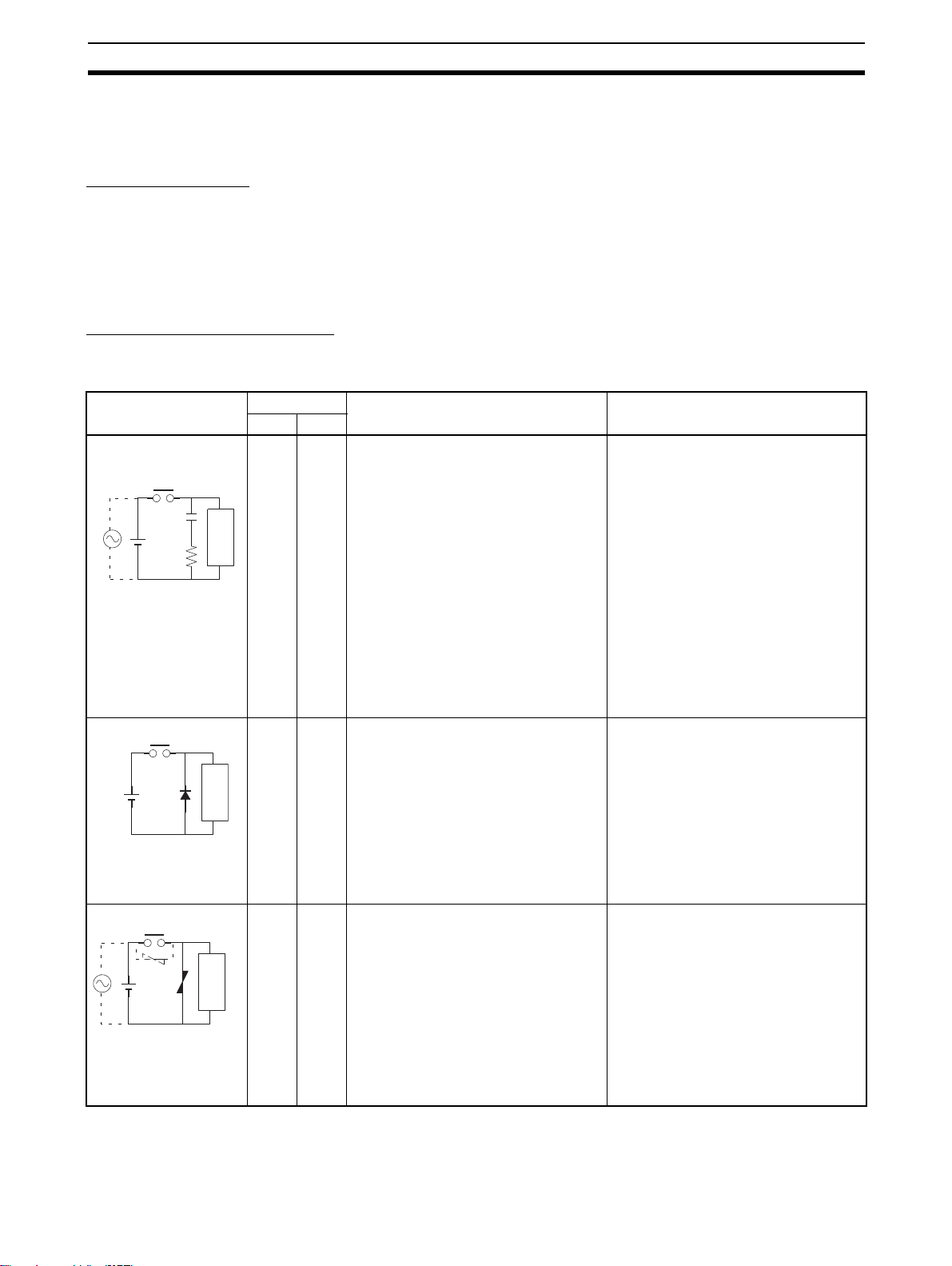
Countermeasure Examples
When switching an inductive load, connect an surge protector, diodes, etc., in
parallel with the load or contact as shown below.
Circuit Current Characteristic Required element
AC DC
The capacitance of the capacitor must
be 1 to 0.5 µF per contact current of
1 A and resistance of the resistor must
be 0.5 to 1 Ω per contact voltage of
1 V. These values, however, vary with
the load and the characteristics of the
relay. Decide these values from experiments, and take into consideration that
the capacitance suppresses spark discharge when the contacts are separated and the resistance limits the
current that flows into the load when
the circuit is closed again.
The dielectric strength of the capacitor
must be 200 to 300 V. If the circuit is an
AC circuit, use a capacitor with no
polarity.
The reversed dielectric strength value
of the diode must be at least 10 times
as large as the circuit voltage value.
The forward current of the diode must
be the same as or larger than the load
current.
The reversed dielectric strength value
of the diode may be two to three times
larger than the supply voltage if the
surge protector is applied to electronic
circuits with low circuit voltages.
---
CR method
C
Power
supply
R
Diode method
Power
supply
Varistor method
Powe r
supply
Yes Yes If the load is a relay or solenoid, there is
a time lag between the moment the circuit is opened and the moment the load
is reset.
If the supply voltage is 24 or 48 V,
insert the surge protector in parallel
Inductive
load
No Yes The diode connected in parallel with
Inductive
load
Yes Yes The varistor method prevents the impo-
Inductive
load
with the load. If the supply voltage is
100 to 200 V, insert the surge protector
between the contacts.
the load changes energy accumulated
by the coil into a current, which then
flows into the coil so that the current will
be converted into Joule heat by the
resistance of the inductive load.
This time lag, between the moment the
circuit is opened and the moment the
load is reset, caused by this method is
longer than that caused by the CR
method.
sition of high voltage between the contacts by using the constant voltage
characteristic of the varistor. There is
time lag between the moment the circuit is opened and the moment the load
is reset.
If the supply voltage is 24 or 48 V,
insert the varistor in parallel with the
load. If the supply voltage is 100 to 200
V, insert the varistor between the contacts.
xvi
Page 18

Conformance to EC Directives 6
When switching a load with a high inrush current such as an incandescent
lamp, suppress the inrush current as shown below.
Countermeasure 1
OUT
R
COM
Providing a dark current of
approx. one-third of the rated
value through an incandescent
lamp
Countermeasure 2
R
OUT
COM
Providing a limiting resistor
xvii
Page 19

Conformance to EC Directives 6
xviii
Page 20

This section provides a brief description of PROFIBUS-DP
1-1 Introduction . . . . . . . . . . . . . . . . . . . . . . . . . . . . . . . . . . . . . . . . . . . . . . . . . . . 2
1-2 Protocol architecture . . . . . . . . . . . . . . . . . . . . . . . . . . . . . . . . . . . . . . . . . . . . 2
1-3 Device types . . . . . . . . . . . . . . . . . . . . . . . . . . . . . . . . . . . . . . . . . . . . . . . . . . 4
1-4 PROFIBUS-DP characteristics . . . . . . . . . . . . . . . . . . . . . . . . . . . . . . . . . . . . 5
1-4-1 Bus Access Protocol . . . . . . . . . . . . . . . . . . . . . . . . . . . . . . . . . . . . . 5
1-4-2 Data throughput . . . . . . . . . . . . . . . . . . . . . . . . . . . . . . . . . . . . . . . . 6
1-4-3 Diagnostic functions . . . . . . . . . . . . . . . . . . . . . . . . . . . . . . . . . . . . . 6
1-4-4 Protection mechanisms . . . . . . . . . . . . . . . . . . . . . . . . . . . . . . . . . . . 7
1-4-5 Network states . . . . . . . . . . . . . . . . . . . . . . . . . . . . . . . . . . . . . . . . . 7
1-5 Device Data Base files . . . . . . . . . . . . . . . . . . . . . . . . . . . . . . . . . . . . . . . . . . 8
1-6 Profiles . . . . . . . . . . . . . . . . . . . . . . . . . . . . . . . . . . . . . . . . . . . . . . . . . . . . . . 8
SECTION 1
PROFIBUS-DP
1
Page 21

Introduction Section 1-1
1-1 Introduction
PROFIBUS is a vendor-independent, open fieldbus standard for a wide range
of applications in manufacturing, process and building automation. Vendor
independence and openness are guaranteed by the PROFIBUS standard
EN 50170. With PROFIBUS, devices of different manufacturers can commu-
Standard EN50170
High speed PROFIBUS-DP
Process Automation PROFIBUS-PA
nicate without special interface adjustments.The PROFIBUS family consists
of three compatible versions:
DP stands for Decentralised Periphery. It is optimised for high speed and lowcost interfacing, especially designed for communication between automation
control systems and distributed I/O at the device level.
PA stands for Process Automation. It permits sensors and actuators to be
connected on one common bus line even in intrinsically-safe areas. It permits
data communication and power supply over the bus using 2-wire technology
according the international standard IEC 1158-2.
Higher level PROFIBUS-FMS
FMS stands for Fieldbus Message Specification. This version is the general-
purpose solution for communication tasks at a higher level. Powerful services
open up a wide range of applications and provide great flexibility. It can also
be used for extensive and complex communications tasks.
Uniform bus access
protocol
!Caution It is not possible to exchange one of these family members by another family
PROFIBUS-DP and PROFIBUS-FMS use the same transmission technology
and a uniform bus access protocol. Thus, both versions can be operated
simultaneously on the same cable. However, FMS field devices cannot be
controlled by DP masters or vice versa.
member. This will cause faulty operation.
The rest of this section only describes PROFIBUS-DP.Protocol architecture
1-2 Protocol architecture
OSI The PROFIBUS protocol architecture is oriented on the OSI (Open System
Interconnection) reference model in accordance with the international standard ISO 7498. Layer 1 (physical layer) of this model defines the physical
transmission characteristics. Layer 2 (data link layer) defines the bus access
protocol. Layer 7 (application layer) defines the application functions
2
Page 22

Protocol architecture Section 1-2
DP-Profiles
DP-Extensions
User Interface Layer DP Basic Functions
(7) Application Layer
(6) Presentation Layer
(5) Session Layer NOT DEFINED
(4) Transport Layer
(3) Network Layer
(2) Data Link Layer Fieldbus Data Link (FDL)
(1) Physical Layer RS-485 / Fibre Optics
Layer 1, 2 and user
interface
PROFIBUS-DP uses layers 1 and 2, and the user interface. Layers 3 to 7 are
not defined. This streamlined architecture ensures fast and efficient data
transmission. The application functions which are available to the user, as
well as the system and device behaviour of the various PROFIBUS-DP device
types, are specified in the user interface.
Transmission medium
RS-485 transmission technology or fibre optics are available for transmission.
RS-485 transmission is the most frequently used transmission technology. Its
application area includes all areas in which high transmission speed and sim-
High-speed, inexpensive
ple inexpensive installation are required. Twisted pair shielded copper cable
with one conductor pair is used.
Easy installation The RS-485 transmission technology is very easy to handle. Installation of the
twisted pair cable does not require expert knowledge. The bus structure permits addition and removal of stations or step-by-step commissioning of the
system without influencing the other stations. Later expansions have no effect
on stations which are already in operation. Transmission speeds between 9.6
kbit/s and 12 Mbit/s can be selected. One unique transmission speed is
selected for all devices on the bus when the system is commissioned.
Cable length The maximum cable length depends on the transmission speed (see
Fieldbus cabling
3-3-1 Fieldbus cabling
). The specified cable lengths are based on type-A cable (see
). The length can be increased by the use of repeaters.
3-3-1
The use of more than 3 repeaters in series is not recommended.
3
Page 23

Device types Section 1-3
1-3 Device types
PROFIBUS distinguishes between master devices and slave devices.
Master devices Master devices determine the data communication on the bus. A master can
send messages without an external request, as long as it holds the bus
access right (the token). Masters are also called active stations in the PROFIBUS standard.
DPM1, DPM2 There are two types of master devices: DP master class 1 (DPM1) and DP
master class 2 (DPM2).
A DPM1 is a central controller which exchanges information with the decen-
tralised stations (i.e. DP slaves) within a specified message cycle.
DPM2 devices are programmers, configuration devices or operator panels.
They are used during commissioning, for configuration of the DP system, or
for operation and monitoring purposes.
Slave devices Slave devices are peripheral devices. Typical slave devices include input/out-
put devices, valves, drives, and measuring transmitters. They do not have bus
access rights and they can only acknowledge received messages or send
messages to the master when requested to do so. Slaves are also called passive stations.
The CJ1W-PRT21 is a PROFIBUS-DP slave device.
4
Page 24
PROFIBUS-DP characteristics Section 1-4
1-4 PROFIBUS-DP characteristics
1-4-1 Bus Access Protocol
Layer 2 The bus access protocol is implemented by layer 2. This protocol also
includes data security and the handling of the transmission protocols and
messages.
Medium Access Control The Medium Access Control (MAC) specifies the procedures which determine
when a station is permitted to transmit data. A token passing procedure is
used to handle the bus access between master devices, and a polling procedure is used to handle the communication between a master device and its
assigned slave device(s).
Token passing The token passing procedure guarantees that the bus access right (the token)
is assigned to each master within a precisely defined time frame. The token
message, a special message for passing access rights from one master to the
next master, must be passed around the logical token ring - once to each
master - within a specified target rotation time. Each master executes this procedure automatically. A user can only change the target rotation time, but is
not recommended.
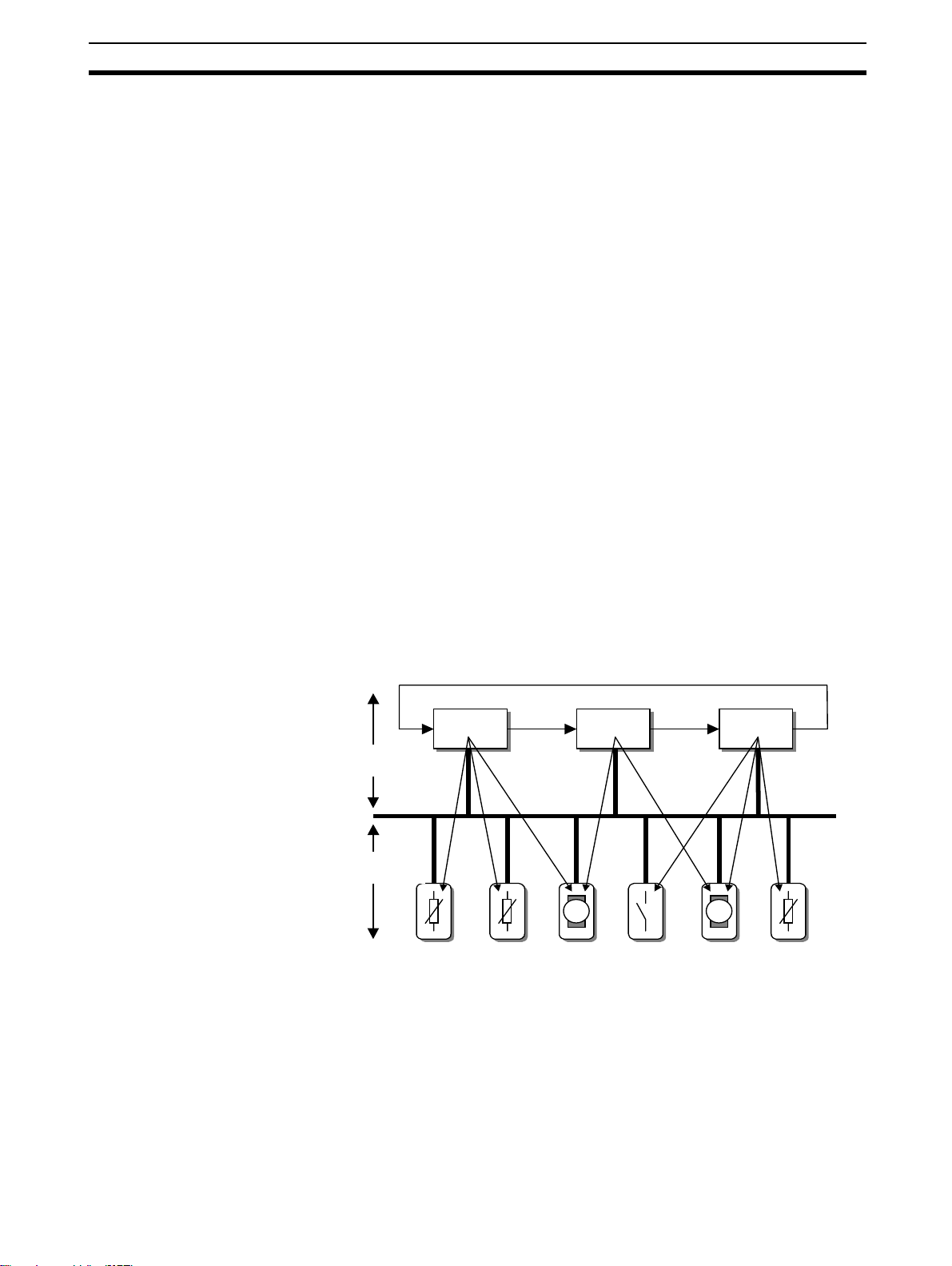
Polling procedure The polling or master-slave procedure permits the master, which currently
owns the token, to access its assigned slaves. The picture below shows a
possible configuration The configuration shows three active stations (masters) and six passive stations (slaves).
.
Token Passing
DPM1 DPM2 DPM1
Active stations
Master devices
Passive stations
Slave devices
The three masters form a logical token ring. When an active station receives
the token message, it can perform its master role for a certain period of time.
During this time it can communicate with all assigned slave stations in a master-slave communication relationship, and a DPM2 master can take the initiative to communicate with DPM1 master stations in a master-master
communication relationship.
Polling
PROFIBUS
5
Page 25
PROFIBUS-DP characteristics Section 1-4
Multi-peer communication In addition to logical peer-to-peer data transmission, PROFIBUS-DP provides
multi-peer communication (broadcast and multicast).
Broadcast communication: an active station sends an unacknowledged
message to all other stations (masters and
slaves).
Multicast communication: an active station sends an unacknowledged
message to a predetermined group of stations
(masters and slaves).
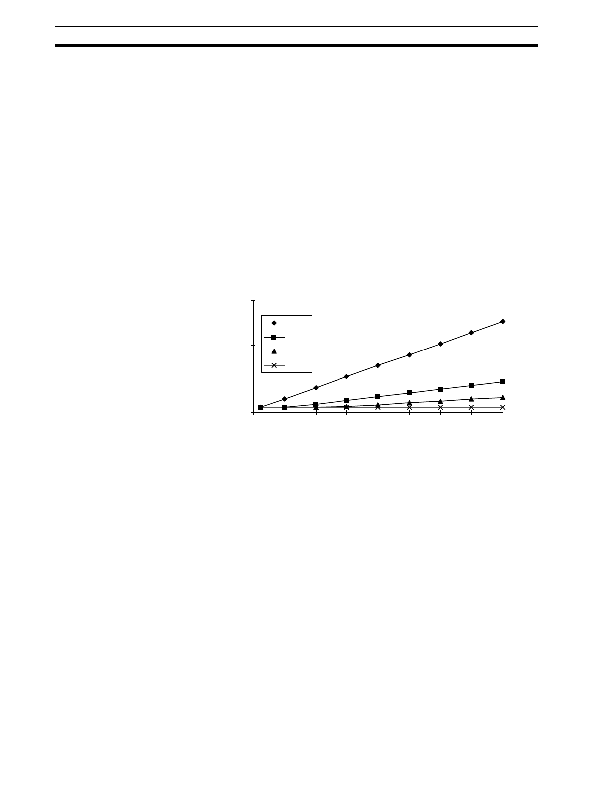
1-4-2 Data throughput
Transmission time At 12 Mbit/s, PROFIBUS-DP requires only about 1 ms for the transmission of
512 bits of input data and 512 bits of output data distributed over 32 stations.
The figure below shows the typical PROFIBUS-DP transmission time depending on the number of stations and the transmission speed. The data throughput will decrease when more than one master is used.
Baud Rate
(kbit/s)
500
1500
3000
12000
0 4 8 12 16 20 24 28 32
Slaves
Bus cycle time [ms]
25.0
20.0
15.0
10.0
5.0
0.0
1-4-3 Diagnostic functions
Extensive diagnostics The extensive diagnostic functions of PROFIBUS-DP enable fast location of
faults. The diagnostic messages are transmitted over the bus and collected at
the master. These messages are divided into three levels:
Device related diagnostics • Device related diagnostics
These messages concern the general operational status of the whole device
(e.g. overtemperature or low voltage).
Module related
diagnostics
• Module related diagnostics
These messages indicate that a fault is present in a specific I/O range (e.g. an
8-bit output module) of a station.
Channel related
diagnostics
6
• Channel related diagnostics
These messages indicate an error at an individual input or output (e.g. short
circuit on output 5).
Page 26

PROFIBUS-DP characteristics Section 1-4
1-4-4 Protection mechanisms
Time monitoring PROFIBUS-DP provides effective protection functions against parameterisa-
tion errors or failure of the transmission equipment. Time monitoring is provided at the DP master and at the DP slaves. The monitoring interval is specified during the configuration.
At the master • Protection mechanism at the master.
The DPM1 master monitors data transmission of its active slaves with the
Data_Control_Timer. A separate control timer is used for each slave. This
timer expires when correct data transmission does not occur within the monitoring interval.
If the master’s Auto_Clear mode is enabled, the DPM1 exits the ’Operate’
state, switches the outputs of all assigned slaves to fail-safe status, and
changes to its ’Clear’ state (see also
At the slave • Protection mechanisms at the slave.
The slave uses the watchdog control to detect failures of the master or the
transmission line. If no data communication with the master occurs within the
watchdog control interval, the slave automatically switches its outputs to the
fail-safe status. This mechanism can be enabled or disabled for each individual slave.
Also, access protection is available for the inputs and outputs of the DP
slaves operating in multi-master systems. This ensures that direct access can
only be performed by the authorised master. For other masters, the slaves
offer an image of their inputs and outputs, which can be read by any master,
even without access rights.
1-4-5 Network states
).
1-4-5 Network states
PROFIBUS-DP distinguishes four different network states.
Off-line • Off-line
Communication between all DP participants is stopped.
Stop • Stop
Communication between DPM1 and DP slaves is stopped. Only communication between DPM1 and DPM2 is possible.
Clear • Clear
DPM1 master attempts to set parameters, check the configuration, and subsequently perform data exchange with its associated DP-slaves. The data
exchange comprises reading the inputs of the DP-slaves and writing zero’s to
the outputs of the DP-slaves.
Operate • Operate
DPM1 master exchanges data with its assigned slaves, inputs are read and
outputs are written. Beside this, the DPM1 cyclically sends its local status to
all assigned DP slaves (with a multicast message) at a configurable time
interval.
Auto_Clear When an error occurs during the data transfer phase of the DPM1, the
‘Auto_Clear’ configuration setting determines the subsequent actions. If this
parameter is set to false, the DPM1 remains in the 'Operate' state. If set to
true, the DPM1 switches the outputs of all assigned DP slaves to the fail-safe
state and the network state changes to the 'Clear' state.
7
Page 27

Device Data Base files Section 1-5
1-5 Device Data Base files
GSD-file To achieve straightforward configuration of a PROFIBUS-DP network, the
characteristic features of a device are specified in a file. This file is called a
GSD-file (Gerätestammdaten file). The language of the GSD file is expressed
with the last letter from the extension, *.GS?:
Default: =GSD
English =GSE
Deutsch =GSG
Italian =GSI
Portuguese =GSP
Spanish =GSS
The GSD files are prepared individually by the vendor for each type of device,
according to a fixed format. Some parameters are mandatory, some have a
default value and some are optional. The device data base file is divided into
three parts:
General section • General specifications
This section contains the vendor name, the device name, hardware- and software release versions, station type and identification number, protocol specification and supported baud rates.
DP-master section • DP master-related specifications
This section contains all parameters which only apply to DP master devices
(e.g. maximum memory size for the master parameter set, maximum number
of entries in the list of active stations, or the maximum number of slaves the
master can handle).
DP-slave section • DP slave-related specifications
This section contains all specification related to slaves (e.g. minimum time
between two slave poll cycles, specification of the inputs and outputs, and
consistency of the I/O data).
Configurator The device data base file of each device is loaded in the configurator and
downloaded to the master device. Refer to the Operation Manual of the
PROFIBUS-DP Master Unit for usage of the GSD file in the master's configuration software.
GSD files are usually supplied with each unit. Alternatively, GSD files can be
downloaded from the Internet, either from the manufacturer's site, or from the
GSD library of the PROFIBUS Nutzerorganisation at http://www.profibus.com.
1-6 Profiles
Exchanging devices To enable the exchange of devices from different vendors, the user data has
to have the same format. The PROFIBUS-DP protocol does not define the
format of user data, it is only responsible for the transmission of this data. The
format of user data may be defined in so called profiles. Profiles can reduce
engineering costs since the meaning of application-related parameters is
specified precisely. Profiles have been defined for specific areas like drive
technology, encoders, and for sensors / actuators.
8
Page 28

SECTION 2
Features and System Configuration
This section describes the overall specification and the communication performance of the PROFIBUS-DP CJ1W-PRT21
Slave Unit
2-1 Overall Specification. . . . . . . . . . . . . . . . . . . . . . . . . . . . . . . . . . . . . . . . . . . . 10
2-2 Dimensions . . . . . . . . . . . . . . . . . . . . . . . . . . . . . . . . . . . . . . . . . . . . . . . . . . . 11
2-3 Performance . . . . . . . . . . . . . . . . . . . . . . . . . . . . . . . . . . . . . . . . . . . . . . . . . . 12
9
Page 29
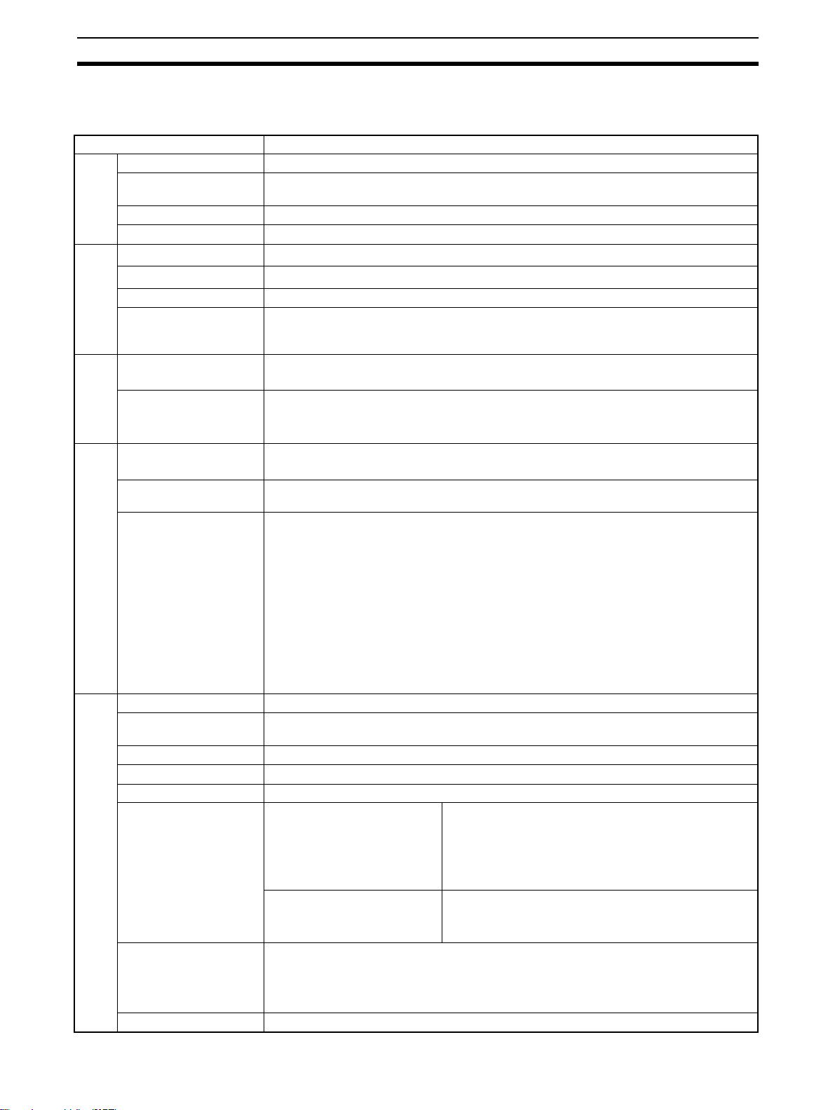
Overall Specification
2-1 Overall Specification
Modal code CJ1W-PRT21
Host PLC System CJ1
Maximum number of
Units per PLC system
Current consumption 400 mA (maximum) at 5V DC from PLC power supply
Weight 90 g (typical)
Installation
Storage temperature
Operating temperature
Operating humidity 10 to 90% (non-condensing)
Conformance to EMCand environmental
standards
Environment
Switch settings Special I/O Machine number (00-95) by 2 rotary switch
LED Indicators Unit status: RUN (green LED), ERC (red LED)
User
Interface
No. of CIO words allocated
No. of DM words allocated
Amount of I/O data per
Unit
PLC Interface
Applicable standard EN50170 Vol. 2
Conformance to
PROFIBUS standard
Bus connector 9-pin female sub-D connector (RS-485 PROFIBUS connector)
Bus address 0 to 99, Remote setting
Baud rate (auto-detect) 9.6k, 19.2k, 45.45k, 93.75k, 187.5k, 500k, 1.5M, 3M, 6M, 12M bit/s
Supported functions
(as responder)
Station type Modular station, max. 32 modules
GSD file OC_0602.GSD, supplied with the unit
Profibus Interface
40
o
C to +70oC
-20
o
0
C to +55oC
EN50081-2
EN61131-2
PROFIBUS-DP node address (00-99) by 2 rotary switches
Network status: COMM (green LED), BF (red LED)
CPU status: ERH (red LED)
PLC -> Unit: 1 word control data
Unit -> PLC: 1 word status data
Unit -> PLC: 8 words of Unit setup information
Fixed:
2 words CIO area (one in, one out) for Unit status + control bits.
2 words status information from the host PLC, containing operation status and error
code (read from location A400). This information will be sent to the PROFIBUS master:
• as extended diagnostics, only at a change of data content.
• optionally, attached to the I/O data, each PROFIBUS cycle.
Variable :
2 user-defined areas for PROFIBUS I/O data, with the following restrictions:
• Up to 100 words input in one PLC area (CIO, H, D, EM).
• Up to 100 words output in one PLC area (CIO, H, D, EM).
• Inputs+outputs must be 180 words or less
Certificate No. Z01033
to DPM1 + DPM2 masters Data_Exchange
to DPM2 master only RD_Inp
Configurable with In-, Out-, and I/O-modules of 1, 2, 4, 8, and 16 words
Total of 0~100 words in + 0~100 words.
Sum of Input and Output size can be up to 180 words
Section 2-1
not supported
Slave_Diag
Set_Prm
Chk_cfg
Global_Control (SYNC/FREEZE/CLEAR)
RD_outp
Get_cfg
10
Page 30
Dimensions
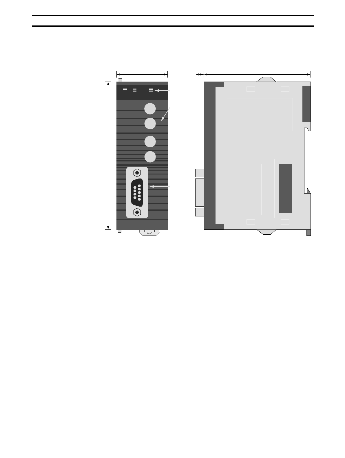
2-2 Dimensions
Section 2-2
The following figure shows the dimensions of the Unit. (All dimensions are in
mm.)
90 mm
PRT21
RUN ERC
31 mm
COMM
ERH BF
Bus
MACH
No.
x10
x10
NODE
No.
x10
x10
1
0
1
0
Indicator
LEDs
Rotar y
switches
D-SUB 9
connector
5 mm
65 mm
11
Page 31

Performance
2-3 Performance
The CJ1W-PRT21’s task is to exchange predetermined amounts of data
between the host PLC system and a PROFIBUS-DP master unit. Its performance in terms of data transfer rate is therefore mainly governed by two factors
external to the Unit: the PROFIBUS-DP cycle time and the host PLC’s cycle
time.
The PLC cycle and the PROFIBUS-DP cycle will generally be:
• independent,
• of unequal length,
• more or less variable,
Asynchronous and therefore fundamentally asynchronous.
In case the PROFIBUS-DP cycle time is longer than the host PLC cycle time,
it may occur that slave input data, sent by the Unit’s host PLC only during a
single PLC cycle, cannot be read in time by the PROFIBUS master.
Section 2-3
Data sent by host PLC
I/O refresh
Data in slave input buffer
Master-Slave polling
PROFIBUS master input data
Data read by host PLC
I/O refresh
Data in slave output buffer
Master-Slave polling
PROFIBUS master output data
1
2 3 4
1 2 3 4
1
3 4
In case the PROFIBUS-DP cycle time is shorter than the host PLC cycle time,
it may occur that slave output data, sent by the PROFIBUS master only during
a single fieldbus cycle, cannot be read in time by the Unit’s host PLC.
ADFC
AB
A
B C D
CDE
E F
F
If it is necessary that each different set of transmitted data is acknowledged
by the receiving side, the user will have to implement a verification mechanism in the PLC programs on both the master and the slave PLC. An example
is to reserve one byte/word in the master’s data block for a transmission counter, which is copied back by the slave in its reply. The master may only transmit the next data if the received counter value equals the sent value,
indicating that the previous data was received by the slave.
Consistency The CJ1W-PRT21 guarantees consistency over the full length of the PROFI-
BUS data message, i.e. all I/O data in one PROFIBUS message is transferred
to the host PLC in one I/O refresh, and vice versa. There are added modules
without consistency which simplify communication with Siemens S7 masters.
12
Page 32

Performance
PROFIBUS-DP cycle time The overall PROFIBUS-DP communication cycle time will depend on the
number and types of PROFIBUS-DP master(s) and other slaves connected to
the network, and the overall bus parameters defined in the configuration of
the master unit(s).
The time required to exchange I/O data between the CJ1W-PRT21 and its
master will depend on the number of input and output words defined in the
master’s configuration, the selected baud rate, and on the performance of the
master unit itself.
The minimum time interval between subsequent I/O data exchanges with the
CJ1W-PRT21 (minimum slave interval) is 0.5 ms as defined in the Unit’s GSD
file.
PLC cycle time The host PLC’s cycle time mainly depends on the size of the PLC program
and the I/O refresh times of all I/O Units on its backplanes. The size of the
PLC program is application specific. Besides optimising the PLC program, the
program execution time can only be decreased by using a faster CPU Unit.
I/O Refresh Time The total I/O refresh time depends on the types of Units that are mounted. Not
all Units refresh the same amount of data. The I/O refresh time of the CJ1WPRT21 depends on the number of I/O data words that have been mapped.
Section 2-3
For the CJ1G CPU45:
I/O Refresh Time = n x 1 µs.
n = number of I/O data words
Maximum words = 184, so maximum I/O refresh time becomes 184 x 1 µs =
0.184 ms
13
Page 33

Page 34

This section describes the installation of the PROFIBUS-DP CJ1W-PRT21 Slave Unit
3-1 Physical layout of the Unit . . . . . . . . . . . . . . . . . . . . . . . . . . . . . . . . . . . . . . . 16
3-1-1 LEDs . . . . . . . . . . . . . . . . . . . . . . . . . . . . . . . . . . . . . . . . . . . . . . . . . 16
3-1-2 Rotary Switches . . . . . . . . . . . . . . . . . . . . . . . . . . . . . . . . . . . . . . . . 16
3-1-3 BUS Connector . . . . . . . . . . . . . . . . . . . . . . . . . . . . . . . . . . . . . . . . . 17
3-2 Connecting PC Components . . . . . . . . . . . . . . . . . . . . . . . . . . . . . . . . . . . . . . 18
3-3 Setting up a network . . . . . . . . . . . . . . . . . . . . . . . . . . . . . . . . . . . . . . . . . . . . 21
3-3-1 Fieldbus cabling . . . . . . . . . . . . . . . . . . . . . . . . . . . . . . . . . . . . . . . . 21
3-3-2 Configuring PROFIBUS-DP systems . . . . . . . . . . . . . . . . . . . . . . . . 23
SECTION 3
Installation
15
Page 35

Physical layout of the Unit Section 3-1
3-1 Physical layout of the Unit
PRT21
RUN ERC
COMM
ERH BF
Bus
MACH
No.
x10
x10
NODE
No.
x10
x10
1
0
1
0
Indicator
LEDs
Rotar y
switches
D-SUB 9
connector
The front view shows the indicator LEDs, the rotary switches, and the 9-pin
female sub-D PROFIBUS-DP connector.
3-1-1 LEDs
The CJ1W-PRT21 has 5 indicator LEDs.
Three LEDs (RUN, ERC
and ERH) give a status
indication of the Unit in
general.
During normal operation, the RUN and COMM LEDs (green) should be ON,
while the ERC, ERH and BF LEDs (red) should be OFF. Refer to
for a detailed description of the LED functions.
3-1-2 Rotary Switches
The CJ1W-PRT21 has 4 rotary switches to:
Note Always turn off the power to the PLC before changing a rotary switch setting.
The Unit only reads the settings during the initialisation after power-on.
Use a small flat-blade screwdriver to turn the rotary switches; be careful not to
damage the switches.
PRT21
RUN ERC
COMM
ERH BF
Two LEDs (COMM and
BF) are related to the
status of the PROFIBUSDP network.
• set its Special I/O Unit number or Machine No. (00-95)
• set the PROFIBUS-DP node address (00-99)
4-8 LEDS
16
Page 36

Physical layout of the Unit Section 3-1
MACH No. The MACH No. rotary switches are used to select the CJ1 Special I/O Unit
number or so called “Machine No.”.
The Special I/O number setting determines which words in the CIO Area and
Data Memory Area are allocated to the CJ1W-PRT21.
Any Machine number in the setting range is allowed as long as it has not been
set on another Special I/O Unit connected to the PLC. If the same number is
used for the CJ1W-PRT21 and another Special I/O Unit, an Unit/Rack Number Duplication error (FALS 80E9) will occur in the PLC, and it will not be possible to start up the PROFIBUS-DP Slave communication see (
Device specific parameters and diagnostics
).
Appendix B
NODE ADDRESS Two switches, marked Node No. x10
1
and x100, are used to set the PROFI-
BUS-DP node address of the Unit. Addresses in the range of 00 through 99
are valid. Be sure the node address on the unit is equal to the station address
in the masters configuration.
3-1-3 BUS Connector
The fieldbus connector is a 9-pin female sub-D connector, as recommended
in the PROFIBUS standard EN50170 Vol.2.
Table 1 Profibus Connector
Pin No. Signal Description
1 Shield Shield / functional ground
2- -
3 B-line Data signal
4 RTS Direction control signal for repeaters (TTL)
5 DGND Data ground
6 VP Supply voltage for terminator resistance (+5V)
7- -
8 A-line Data signal
9- -
Data Signal The PROFIBUS User Group recommends the following colour coding for the
data signal lines:
A-line = Green B-line = Red
These data signal lines must be connected to the corresponding signal terminals or pins at the master unit and other stations (i.e. A to A, B to B). For
detailed PROFIBUS-DP cable requirements, see
3-3-1 Fieldbus cabling
.
RTS The signal RTS (TTL signal relative to DGND) is meant for the direction con-
trol of repeaters in case repeaters without self control capability are used
17
Page 37

Connecting PC Components Section 3-2
VP, DGND The signals VP and DGND are meant to
power an externally mounted bus terminator.
The powering of the 220 Ω termination
resistor ensures a defined idle state
potential on the data lines. To ensure
proper functioning up to the highest
baud rate, each bus segment has to be
terminated at both ends of the cable.
3-2 Connecting PC Components
The Units that make up a CJ-series PC can be connected simply by pressing
the Units together and locking the sliders by moving them toward the back of
the Units. The End Cover is connected in the same way to the Unit on the far
right side of the PLC. Follow the procedure listed below to connect PLC components.
1,2,3...
1. The following diagram shows the connection of two Units that make up a
CJ-series PLC. Join the Units so that the connectors fit exactly.
VP
390Ω
B-line
220Ω
A-line
390Ω
DGND
18
Page 38

Connecting PC Components Section 3-2
2. The yellow sliders at the top and bottom of each Unit lock the Units
together. Move the sliders toward the back of the Units as shown below until they click into place.
Note If the locking tabs are not secured properly, the CJ-series PLC may not func-
tion properly. Be sure to slide the locking tabs until they are securely in place.
3. Attach the End Cover to the Unit on the far right side of the Rack.
CPU Rack
Note Connect the I/O Control Unit directly to the CPU Unit to enable connecting
Expansion Racks.
Expansion Rack
Note Connect the I/O Interface Unit directly to the Power Supply Unit.
There is no Backplane for the CJ-series. The PC is constructed by connecting
Units together using the connectors on the sides.
19
Page 39

Connecting PC Components Section 3-2
!Caution Attach the End Cover to the Unit on the far right side of the Rack. An I/O bus
error will occur and the PC will not operate in either RUN or MONITOR mode
if the End Cover is not connected. If this occurs, the following information will
be set in memory.
Name Address Status
I/O Bus Error Flag A 40114 ON
I/O Bus Error Slot Number A40400 to A40407 0E Hex
I/O Bus Error Rack Number A40408 to A40415 0E Hex
Note 1. Always turn OFF the power supply before connecting Units to each other.
2. Always turn OFF the power supply to the entire system before replacing a
Unit.
A maximum of 10 I/O Units can be connected to a CPU Rack or an Expansion
Rack. If 11 or more I/O Units are connected, and I/O overflow error will occur
and the PC will not operate in either RUN or MONITOR mode. If this occurs,
FALS(80E9) occurs, the Too Many I/O Points error flag (A40111) will turn ON
and A40713 to A40715 (I/O Overflow Details) will turn ON (see
Device specific parameters and diagnostics
).
Appendix B
20
Page 40

Setting up a network Section 3-3
3-3 Setting up a network
3-3-1 Fieldbus cabling
Bus structure All PROFIBUS-DP devices are connected in a line structure. Each RS-485
bus segment may contain up to 32 stations (masters, slaves, repeaters).
When more than 32 stations are required, repeaters must be used to link the
individual bus segments. The bus must be terminated at the beginning and at
the end of each segment.
Cable type The standard EN50170 Vol.2 specifies to use shielded twisted pair cables
with the following parameters (PROFIBUS line type A):
Table 2 PROFIBUS Cable parameters
Parameter Value
Impedance 135 to 165 Ω (3 to20 MHz)
Capacitance per unit length < 30 pF/m
Loop resistance < 110 W/km
Core diameter > 0.64 mm
Core cross section > 0.34 mm (22 AWG)
Maximum length The maximum length of the cable depends on the transmission speed. The
cable lengths specified in the table below are based on the above cable specifications.
Table 3 Maximum cable lengths
Baud rate (kbit/s) Length/segment (m)
9.6, 19.2, 45.45, 93.75 1200
187.5 1000
500 400
1500 200
3000, 6000, 12000 100
Repeaters The maximum communication distance as specified in
increased by the use of repeaters. The repeater must be included in the count
of the number of stations on the segment. Even though repeaters do not have
a node address, they represent an electrical load on the bus segment like any
master or slave station.
If a repeater is located at the end of a bus segment, it should provide bus termination as well.
It is recommended to limit the number of repeaters in series between any two
stations in the system to a maximum of three units, as shown in the following
example (3 repeaters are encountered in communication between segment 6
and segments 1, 2 and 4).
Tab le 3
can be
21
Page 41

Setting up a network Section 3-3
Segment 1
Max. 31 Stations
M/S
REP REP
REP
Segment 4
Segment 5
Max. 31 Stations
Max. 31 Stations
M/S
M/S
Master or slave station
Repeater
REP
Te r m i na t io n
Max. total number of stations = 126
Segment 2
Max. 31 Stations
M/S
Segment 3
Max. 31 Stations
M/S
REP
M/S
REP
Segment 6
Max. 31 Stations
M/S
Stub lines Stub lines (branches from the main line) should be avoided for data transmis-
sion speeds of more than 500 kbit/s. Except at end stations with termination, it
is recommended to always use plug connectors that permit two data cables to
be connected directly to the plug. This method allows the bus connector to be
plugged and unplugged at all times without interrupting data communication
between other stations.
22
Page 42

Setting up a network Section 3-3
Fieldbus connector The connector plug to be used on the CJ1W-PRT21 is a 9-pin male sub-D
connector, preferably with a metal case, and a facility to connect the shield of
the cable to the case. The cable should at least be connected to pin 3 (B-line)
and pin 8 (A-line) of the connector.
At baud rates of 1.5 Mbit/s or higher, always use special PROFIBUS-DP connectors with built-in series inductances, to ensure that cable reflections
caused by the capacitive the load of each unit are minimised.
Connectors with built-in inductors and termination resistors, as shown here
schematically, are available from various manufacturers.
To ensure electromagnetic compatibility (EMC), the shield of the cable should
be connected to the metal case of the connector. If this is impossible, use pin
1.
When the Unit is installed within a control cabinet, the cable shield of the bus
cable should be electrically connected to a grounding rail as close as possible
to the cable lead-through using a shield grounding clamp or similar. The cable
shield should continue within the cabinet to the fieldbus device. Ensure that
the PLC and the control cabinet in which the device is mounted have the
same ground potential by providing a large-area metallic contact to ground
(use e.g. galvanised steel to ensure a good connection). Grounding rails
should not be attached to painted surfaces.
You may find further information about:
• Commissioning of PROFIBUS equipment
• Testing the PROFIBUS cable and bus connectors
• Determining the loop resistance
• Testing for correct bus termination
• Determining the segment length and cable route
• Other test methods
• Example of an equipment report
in the PROFIBUS guideline "Installation Guideline for PROFIBUS-DP/FMS"
(PNO Order No- 2.112), which is available at every regional PROFIBUS user
organisation.
3-3-2 Configuring PROFIBUS-DP systems
After making the physical connections of the network, the PROFIBUS-DP
system needs to be configured. For each master and its assigned slaves, a
configuration has to be defined using a dedicated configuration program.
Configurator The configurator provides the master with information about:
• The slaves that are connected to the master.
• The assignment of slaves to groups for broadcast / multicast messages.
• The mapping of the slaves into the memory of the master.
• The bus parameters (e.g. baud rate, target rotation time etc.).
23
Page 43

Setting up a network Section 3-3
C200HW-PRM21 For more details about the configurator for the C200HW-PRM21 Master Unit,
refer to OMRON Catalog No. W349-E1.
GSD file To configure a master unit to communicate with the CJ1W-PRT21, the Unit’s
device database file OC_0602.GSD is required. Based on the contents of this
file, the configuration program for the master unit will allow the user to specify
the amount of input- and output data to be exchanged. The sizes of the inand the output block can both be set in 1-word increments from 0 to 100
words.
Modular slave The CJ1W-PRT21 is characterised as a modular slave. The following types of
data exchange modules are pre-defined:
IN modules of 1, 2, 4, 8, and 16 words
OUT modules of 1, 2, 4, 8, and 16 words
IN/OUT modules of 1+1, 2+2, 4+4, 8+8, and 16+16 words
By concatenating up to 32 modules, any desired size of input and output block
can be created (multiple selections of any module type are allowed). The
sequence in which the modules are entered is irrelevant. Only the resulting
total lengths of the input and output areas are of significance.
Check configuration Upon startup of the PROFIBUS-DP communication, the master unit will send
a Chk_Cfg message so that the slave can verify that the master’s expected
I/O configuration for the slave is correct.
The CJ1W-PRT21 Slave Unit will accept any in/ out words up to 100 input,
100 output words. The maximum of input + outputs must be 180 words or
less.
Parameter data The Set_Prm telegram will provide the following information at system star-
tup, after a restart and in data exchange mode:
• Start address of the area in the host PLC where to read and to send to the
master.
• Format (Motorola/Intel) of the data to be sent to the master.
• Actions to be taken in case of PLC status change or fatal errors.
• Inclusion of 2 words PLC status information or not.
24
Page 44

Setting up a network Section 3-3
Fail safe support:
Off: After the master sends a global control command ‘CLEAR’, the slave
requires data telegramcontaining 0000 as data, in order to remain in
data exchange mode.
On: After the master sends a global control command ‘CLEAR’, the slave
can accept data telegrams containing no data, while still remaining in
data exchange mode
Watchdog Base:
The slave uses the watchdog control to detect failures of the master or the
transmission line. If no data communication with the master occurs within the
watchdog control interval, the slave automatically switches its outputs to the
fail-safe status. The watchdog control time can be specified in intervals of 1
ms or 10 ms.
Output data on PROFIBUS fail:
The user can select how the slave will behave on the host PLC’s I/O bus in
case the PROFIBUS data exchange communications fails:
• Clear data to Host PLC
• Hold data to Host PLC
Output data format:
The user can select how the data bytes of a PROFIBUS data exchange telegram are mapped to the host PLC data words.
• Motorola
•Intel
4-3 I/O Data Format
See
for details:
Output to slave PLC area:
The user can select the area to which the unit will write PROFIBUS output
data received from its master. See
4-2 I/O Data Mapping
for details.
Output area start address:
Sets the start address in the host PLC to which the PROFIBUS output data,
received from the master, will be written.
Action on slave PLC PROGRAM mode:
Defines how the slave will behave on PROFIBUS in case the host PLC is in
PROGRAM mode (as opposed to RUN or MONITOR mode).
Action on slave PLC I/O bus fail:
Defines how the slave will behave on PROFIBUS in case (the communication
with) the host PLC has a fatal error (CPU ERC LED ON) e.g. I/O refresh timeout.
Input data format:
Defines how Host PLC data words are mapped to a PROFIBUS data
exchange telegram. See
4-3 I/O Data Format
for details.
Input from slave PLC area:
Selects the area from which the unit will read PROFIBUS input data to be sent
to its master.
25
Page 45

Setting up a network Section 3-3
Input area start address:
Sets the start address in the host PLC, from which the PROFIBUS input data,
to be sent to the master, will be read.
Slave PLC status indication:
Selects if the PLC status information should occupy the first two words of
input data to the PROFIBUS master.
Example The example below shows a slave configuration screen. The CJ1W-PRT21 is
configured as a slave with 2 words input for status information and
(16+16+4=) 36 words input data and (16+16+8=) 40 words output data. The
terms input and output are to be interpreted as seen from the PROFIBUS-DP
master unit.
List of available
module types,
defined in GSD file
I/O data limits,
defined in GSD file
Total I/O sizes,
calculated by
Configurator
List of modules,
selected by user
26
Page 46

Setting up a network Section 3-3
Slave PLC status indication configured as
Cyclic by first 2 input words
If the Slave PLC status indication is configured as Cyclic by first 2 input words
then the connections between master and slave are as follows:
Master Slave
st
IN word 1st Slave PLC status word
1
nd
IN word 2nd Slave PLC status word
2
rd
3
IN word
th
IN word
4
CIO 50
CIO 51
...
th
IN word
38
st
1
OUT word
nd
OUT word
2
CIO 85
CIO 350
CIO 351
...
th
OUT word
40
CIO 389
27
Page 47

Page 48

SECTION 4
User Interface
This section describes the Interface between the CJ1-series PLC CPU and the PROFIBUS-DP CJ1W-PRT21 Slave Unit.
4-1 Input and Output Data . . . . . . . . . . . . . . . . . . . . . . . . . . . . . . . . . . . . . . . . . . . 30
4-2 I/O Data Mapping . . . . . . . . . . . . . . . . . . . . . . . . . . . . . . . . . . . . . . . . . . . . . . 31
4-3 I/O Data Format . . . . . . . . . . . . . . . . . . . . . . . . . . . . . . . . . . . . . . . . . . . . . . . 32
4-4 Data Mapping . . . . . . . . . . . . . . . . . . . . . . . . . . . . . . . . . . . . . . . . . . . . . . . . . 33
4-5 Control and status area . . . . . . . . . . . . . . . . . . . . . . . . . . . . . . . . . . . . . . . . . . 34
4-5-2 Control bits . . . . . . . . . . . . . . . . . . . . . . . . . . . . . . . . . . . . . . . . . . . . 34
4-5-1 Allocated CIO words . . . . . . . . . . . . . . . . . . . . . . . . . . . . . . . . . . . . 34
4-5-3 Status Flags . . . . . . . . . . . . . . . . . . . . . . . . . . . . . . . . . . . . . . . . . . . . 35
4-6 Configuration information . . . . . . . . . . . . . . . . . . . . . . . . . . . . . . . . . . . . . . . 39
4-6-1 Allocated DM words. . . . . . . . . . . . . . . . . . . . . . . . . . . . . . . . . . . . . 39
4-6-2 Slave Parameter Data . . . . . . . . . . . . . . . . . . . . . . . . . . . . . . . . . . . . 40
4-6-3 Slave Output Data . . . . . . . . . . . . . . . . . . . . . . . . . . . . . . . . . . . . . . . 42
4-6-4 Slave Input Data . . . . . . . . . . . . . . . . . . . . . . . . . . . . . . . . . . . . . . . . 44
4-7 PLC status information . . . . . . . . . . . . . . . . . . . . . . . . . . . . . . . . . . . . . . . . . . 47
4-8 LEDS . . . . . . . . . . . . . . . . . . . . . . . . . . . . . . . . . . . . . . . . . . . . . . . . . . . . . . . . 48
Page 49

Input and Output Data Section 4-1
4-1 Input and Output Data
The CJ1W-PRT21 forms a link between two bus systems: the host PLC’s I/O
bus on one side, and PROFIBUS-DP on the other. The Unit can be considered as a slave to both systems: the I/O bus communication is controlled by
the CPU Unit of the host PLC, the PROFIBUS-DP communication is controlled by a PROFIBUS-DP master.
Definitions Being a slave of two systems may cause confusion as to which data should
be considered ’input data’ and which is ’output data’. In this manual all I/O
data communication is defined from the point of view of the PROFIBUS-DP
system:
Slave INPUT Data Slave INPUT Data is process data which the CJ1W-PRT21 reads from the
assigned areas on demand of the host PLC. The CJ1W-PRT21 sends this
data to the PROFIBUS-DP master unit.
CJ1W-PRT21Host PLC PROFIBUS
I/O Bus
PROFIBUS
Master
Figure 1 Slave INPUT data direction
Slave OUTPUT Data Slave OUTPUT Data is process data which the CJ1W-PRT21 receives from
the PROFIBUS-DP master unit. The CJ1W-PRT21 writes this data to the
assigned areas on demand of the host PLC.
CJ1W-PRT21Host PLC PROFIBUS
I/O Bus
Figure 2 Slave OUTPUT data direction
PROFIBUS
Master
30
Page 50

I/O Data Mapping Section 4-2
4-2 I/O Data Mapping
Data flow The figure below shows the flow of remote I/O data in the PLC system. It is
possible to map the PROFIBUS-DP I/O data to the CIO, D, EM, H or W areas
of the PLC memory. The input and output areas can be assigned independently.
Host PLC
I/O Area
(Not allocated words
I/O Area
(Not used
2
)
Data Link Area
(Not allocated words
Internal I/O Areas
CIO Area
CPU Bus unit area
(Not allocated words
Special I/O Unit Area
(Not allocated words
DeviceNet Area
(Not allocated words
Work Area
Holding Area
Data Memory Area
Purposed for Special I/O
units (not allocated words
CIO 0000-0079
1
)
CIO 0080-0999
CIO 0080-0999
CIO 2960-3199
CIO 1000-1199
1
)
CIO 1200-1499
CIO 3800-6143
1
CIO 1500-1899
)
1
CIO 2000-2959
)
CIO 3200-3799
1
)
D 00000-19999
D 29600-29999
D 31600-32767
D 20000-29599
1
)
W 000-511
H 000-511
I/O BUS
Input + Output = max 180 words
CJ1W-PRT21
Input buffer
Max. 100 words
(200 bytes)
(360 bytes)
Output buffer
Max. 100 words
(200 bytes)
(360 bytes)
PROFIBUS-DP
Input + Output = max 180 words
Purposed for CPU BUS
units (not allocated words
1
D 30000-31599
)
E0_00000-32767Extended Data Memory Area
EC_00000-32767
1
Words that are not allocated can be used
2
Unused words can be used, but those areas may be used in future for expanding functions.
3
The EM Area is divided into 32,767-word regions called banks. The number of EM banks depends upon the
model of CPU Unit (see CJ1 Operation manual 2-1 Specification)
.
Slave input data is transferred via the I/O bus on the PLC Backplane to the
input buffer of the Unit. Each PROFIBUS-DP cycle this data is transmitted to
the master over PROFIBUS. Slave output data received from PROFIBUS is
first stored in the output buffer of the Unit. During an I/O refresh, this data is
transferred to the memory of the host PLC via the I/O Bus.
31
Page 51

I/O Data Format Section 4-3
I/O refresh By default, I/O refreshes are executed at the end of each PLC program cycle,
but they can also be triggered by the IORF instruction. See the applicable
PLC CPU Operation Manual for more details.
Maximum I/O data For CJ1W-PRT21, the maximum amount of mapped I/O data is 100 words
input + 100 words output with the following restrictions:
Input + outputs must be 180 words or less.
4-3 I/O Data Format
The CJ1W-PRT21 allows the user to select between two methods to map the
word-oriented PLC data to the essentially byte-oriented PROFIBUS-DP messages. The default method is Motorola format (Big-Endian), which allows
easy data exchange with other OMRON PROFIBUS-DP devices. For communication with other manufacturers’ devices, in some cases it may be more
convenient to select Intel format (Little-Endian).
Motorola (Big-Endian) By default, the most significant byte of a PLC data word will be mapped to an
even byte in the PROFIBUS-DP message, the least significant byte is
mapped to an odd byte, e.g.
PLC data area PROFIBUS-DP message
bit # bit #
word 15---8 7---0 7---0 byte
0 8 9
1 C D
A B A B 1
E F E F 3
Intel (Little-Endian) Alternatively, selecting Intel format will result in:
PLC data area PROFIBUS-DP message
bit # bit #
word 15---8 7---0 7---0 byte
0 8 9
1 C D
A B A B 0
E F E F 2
D word m+2 bit 12 indicates how the data bytes of a PROFIBUS data telegram are mapped to Host PLC data words:
• 0: Motorola (high byte first),
• 1: Intel (low byte first).
8 9 0
C D 2
8 9 1
C D 3
32
Page 52

Data Mapping Section 4-4
4-4 Data Mapping
The mapping of PROFIBUS I/O data to the host PLC is controlled by the
Set_Prm (set parameter) and Chk_Cfg (Check configuration) telegrams sent
by the PROFIBUS Master. At startup of the PROFIBUS communication the
following commands are sent.
Master Slave
S
l
a
v
e
d
i
a
g
n
o
s
t
i
c
K
O
t
o
N
S
e
t
_
1
P
)
r
m
C
h
k
2
_
)
C
f
g
S
l
a
v
e
d
i
a
g
n
o
s
t
i
c
K
O
D
a
t
a
a
t
a
D
D
a
t
a
a
t
a
D
1)
At system startup, after a restart and in data exchange mode the Set_Prm
telegram will provide the following information:
• Start address of the area in the host PLC where to read to sent to the
master.
• Format (Motorola/Intel) of the data to be sent to the master.
• Actions to be taken in case of PLC status change or fatal errors.
• Inclusion of 2 words PLC status information or not.
2)
The Chk_Cfg telegram will provide the number of words to be read from the
host PLC and to be sent to the Master plus the number of words to be
received from the Master and to be written to the host PLC.
Note 1. Until the Set_Prm and Chk_Cfg have been accepted by the Unit, only the
control- and status CIO words are exchanged with the host PLC. The status information will indicate that no I/O data is exchanged.
2. After the Set_Prm telegram is received by the Unit, it will check if the spec-
ified data areas in the host PLC exist. If not, this will be indicated as a Parameter Fault to the PROFIBUS master, and in CIO n+1.
3. After the Chk_Cfg telegram is received by the Unit, it will check if the spec-
ified data areas in the host PLC exist. If not, this will be indicated as a Configuration Fault to the PROFIBUS master, and in CIO n+1.
4. In case the parameters specify to include PLC status information in the in-
put data, the amount of input data read from the PLC will be 2 words less
than the PROFIBUS input data length. If the input data length is less than
2 words, this is also indicated as a Configuration Fault.
33
Page 53

Control and status area Section 4-5
4-5 Control and status area
After initialisation of the Unit (RUN LED is ON), the control- and status words
are exchanged between the host PLC and the Unit during each I/O refresh.
4-5-1 Allocated CIO words
The CIO words are in the area assigned to the Special I/O unit, depending on
the Machine no. (00-95).
Start address CIO Area = 2000 + <MACH No.> x 10
Table 4 Unit settings area
MACH No. CIO Area MACH No. CIO Area
00 CIO 2000-CIO 2009 06 CIO 2060-CIO 2069
01 CIO 2010-CIO 2019 07 CIO 2070-CIO 2079
02 CIO 2020-CIO 2029 08 CIO 2080-CIO 2089
03 CIO 2030-CIO 2039 09 CIO 2090-CIO 2099
04 CIO 2040-CIO 2049 10 CIO 2100-CIO 2109
05 CIO 2050-CIO 2059 95 CIO 2940-CIO 2949
4-5-2 Control bits
CIO n
The PROFIBUS-DP communication status of CJ1W-PRT21 can be controlled
through the first CIO word (CIO n) allocated via the Machine No. setting (n =
2000 + 10*Mach.No.). The communication status set by these bits is retained
until the Unit is restarted (Power-on or reset). After a restart, PROFIBUS-DP
communication is enabled by default.
1514131211109876543210
Start communication
Stop communication
CIO n.00 Start Communication
0 → 1: PROFIBUS-DP communication will be enabled. If the
communication is already enabled, no specific action
is taken.
1 → 0: No action.
CIO n.01 Stop Communication
0 → 1: PROFIBUS-DP communication will be disabled (Slave
Off-line). If the communication is already disabled, no
specific action is taken.
1 → 0: No action.
34
In case start communication and stop communication are both set from 0 → 1
at the same moment, communication will be enabled (default value).
Page 54

Control and status area Section 4-5
4-5-3 Status Flags
The CJ1W-PRT21 indicates its status in the second CIO word (CIO n+1) allocated via the Machine No. setting. The lower byte shows the PROFIBUS-DP
related status information, the higher byte indicates configuration errors.
At power-on, or after a reset of the unit, the initial value shall be 0000.
In a 'normal' situation only CIO n+1.00 will be ON.
1514131211109876543210
CIO n+1
Data exchange active
CLEAR
FREEZE
SYNC
Watchdog disabled
Watchdog base 1 ms
Fail-safe enabled
Parameter/Configuration error
Incorrect start address (slave input area)
Incorrect end address (slave input area)
Incorrect start address (slave output area)
Incorrect end address (slave output area)
CIO n+1.00 Data exchange active
0: The slave unit is not in data exchange mode.
1: The slave unit is exchanging I/O data with its master.
When this flag is ON, the assigned slave output area of the
Host PLC contains data sent by the PROFIBUS master.
When the flag is off, the user should not process the data
from this area since its validity cannot be guaranteed.
This does not necessarily mean that slave outputs are
updated cyclically:
• If the communication watchdog timer is disabled by the
master (see CIO n+1.04), the I/O data refresh interval
may be of indefinite length.
• In 'Clear' mode (see CIO n+1.01), only the slave inputs
are read, while all slave outputs are forced to 0.
CIO n+1.01 CLEAR
0: Not in CLEAR mode.
1: The master has sent a global control command CLEAR,
which resets all outputs of all the addressed slaves on the
network.
35
Page 55

Control and status area Section 4-5
CIO n+1.02 FREEZE
0: Not in FREEZE mode.
1: The slave has accepted a global control command
FREEZE from its master. The slave input data from the
PLC is not updated at the PROFIBUS-DP interface until the
next FREEZE command to this slave, or until the slave
receives an UNFREEZE command.
CIO n+1.03 SYNC
0: Not in SYNC mode.
1: The slave has accepted a global control command SYNC
from its master. The slave output data to the PLC is not
updated at the PLC I/O bus interface until the next SYNC
command to this slave, or until the slave receives an
UNSYNC command
CIO n+1.04 Watchdog disabled
0: The slave's watchdog is enabled by the PROFIBUS-DP
master, and the actual watchdog time is indicated in
D m+1.
1: The master has disabled the slave's watchdog. If the Mas-
ter-Slave communication fails, the slave will not exit data
exchange mode, and its outputs will keep their state as
received in the last data exchange telegram.
CIO n+1.05 Watchdog timebase 1 ms
0: The slave's watchdog uses the default timebase of 10 ms.
The product of the two watchdog factors indicated by D
m+1 is multiplied by 10 ms to give the actual watchdog
time.
1: The slave's watchdog uses the optional timebase of 1 ms.
The product of the two watchdog factors indicated by D
m+1 is multiplied by 1 ms to give the actual watchdog time.
36
Page 56

Control and status area Section 4-5
CIO n+1.06 Fail_safe enabled
0: After the master sends a global control command CLEAR,
the slave requires data telegrams containing 0000 as data,
in order to remain in data exchange mode.
1: After the master sends a global control command CLEAR,
the slave can accept data telegrams containing no data,
while still remaining in data exchange mode
CIO n+1.08 Parameter/Configuration error
0: The slave unit has received and accepted Set_Prm and
Chk_Cfg telegrams from its master.
1: The slave has not received, or received incorrect parameter
and/or configuration telegrams from a master unit. I/O data
exchange over PROFIBUS-DP will not take place.
Parameter Error can be caused by:
• Invalid standard parameter settings (valid settings are
described in the PROFIBUS standard [4]).
• Invalid user parameter settings (allowed settings are
described in the GSD file of the Unit).
• Incorrect start addresses for I/O data in the host PLC system. If one of them is invalid, parameter error is indicated,
plus CIO n+1.12 and/or CIO n+1.14 will be set.
Configuration Error can be caused by:
• Input- or output length > 100 words
• Input + output length > 180 words
• Input length < 2 words while PLC status should be
included.
• Input- or output length causing errors indicated by
CIO n+1.13, CIO n+1.15
Note When the Parameter/Configuration flag is ON, the status of
CIO n+1.02 - CIO n+1.06 and CIO n+1.08 are not updated.
37
Page 57

Control and status area Section 4-5
CIO n+1.12 Incorrect start address for slave input area
0: No error
1: There is an error in the slave input area mapping. The start
address of the area as specified in the Set_Prm telegram is
invalid for this PLC CPU type.
The BF LED is BLINKING to indicate a configuration- or
parameterisation error; no I/O data is transferred between
master and slave units.
CIO n+1.13 Incorrect end address for slave input area
0: No error
1: There is an error in the slave input area mapping. The end
address of the area as specified by the start address in the
Set_Prm telegram, plus the data length in the Chk_Cfg telegram, is invalid for this PLC CPU type.
The BF LED is BLINKING to indicate a configuration- or
parameterisation error; no I/O data is transferred between
master and slave units.
CIO n+1.14 Incorrect start address for slave output area
0: No error
1: There is an error in the slave output area mapping. The
start address of the area as specified in the Set_Prm telegram is invalid for this PLC CPU type.
The BF LED is BLINKING to indicate a configuration- or
parameterisation error; no I/O data is transferred between
master and slave units.
CIO n+1.15 Incorrect end address for slave output area
0: No error
1: There is an error in the slave output area mapping. The end
address of the area as specified by the start address in the
Set_Prm telegram, plus the data length in the Chk_Cfg telegram, is invalid for this PLC CPU type.
The BF LED is BLINKING to indicate a configuration- or
parameterisation error; no I/O data is transferred between
master and slave units.
38
Page 58

Configuration information Section 4-6
4-6 Configuration information
The CJ1W-PRT21 provides 8 DM words to indicate configuration- and parameterisation data received from the PROFIBUS-DP master unit. These words
are not part of the cyclic refresh, but the unit writes this information to the Host
PLC when the data in the unit changes. At power-on, or at a reset of the unit,
all data will be set to 0. The DM words are in the area assigned to the Special
I/O unit, depending on the Machine No. The first word in the DM area allocated to the Unit will be indicated by D m, the last word by D m+7
Table 5 Overview of Unit settings
D Word Function
m Group assignment (00-FF) Master address (00-7F, FF)
m+1 WD factor 2 (00-FF) WD factor 1 (00-FF)
m+2 Output Data processing flags Output area code
m+3 Output start address
m+4 Output data length
m+5 Input Data processing flags Input area code
m+6 Input start address
m+7 Input data length
The contents will only change:
• When the unit has accepted a Set_Prm and a Chk_Cfg telegram from a
master.
• When the slave exits 'data_exchange' state (resets all data to 0, except
Master address = FF).
The user should make sure not to overwrite this information by the PLC program.
Note DM indication is not synchronised with the PLC's refresh cycle, this informa-
tion is intended for debugging purposes.
4-6-1 Allocated DM words
The DM words are in the area assigned to the Special I/O unit, depending on
the Machine no. (00-95).
Start address DM Area = 20000 + MACH No. x 100
Table 6 Unit settings area
MACH No. DM Area MACH No. DM Area
00 D 20000-D 20007 06 D 20600-D 20607
01 D 20100-D 20107 07 D 20700-D 20707
02 D 20200-D 20207 08 D 20800-D 20807
03 D 20300-D 20307 09 D 20900-D 20907
04 D 20400-D 20407 10 D 21000-D 21007
05 D 20500-D 20507 95 D 29500-D 29507
39
Page 59

Configuration information Section 4-6
4-6-2 Slave Parameter Data
1514131211109876543210
D m
Master address
Group assignment
Group 1
Group 2
Group 3
Group 4
Group 5
Group 6
Group 7
Group 8
D m
low byte
D m
high byte
Master Address
Hexadecimal value (00~7D) indicating the node address of
the PROFIBUS-DP Master from which the Unit has received
and accepted the Chk_Cfg and Set_Prm telegrams. FFh indicates that the slave has not been configured by a master.
Group Assignment
Indicates to which groups (numbered 1-8) the slave has been
assigned by the PROFIBUS-DP master / configurator. When
receiving a global control command, the slave will decide if
the command is intended for a group of slaves to which it has
been assigned.
The value is provided by the PROFIBUS master's Set_Prm
telegram, and indicated in D m after both the Set_Prm and
Chk_Cfg telegrams have been accepted.
40
Page 60

Configuration information Section 4-6
1514131211109876543210
D m+1
Watchdog factor 1
Watchdog factor 2
D m+1 Watchdog Factors
The master's parameterisation telegram contains the value to
which the slave's communication watchdog timer will be set.
The actual watchdog control time is set to WDfact1 * WDfact2
* WD timebase.
The WD timebase can be either 10 ms (default) or 1 ms
(optional). This selection is made by the PROFIBUS master
and indicated in CIO n+1.05.
The actual watchdog control time can have any value from 2
ms (2*1*1) to 650250 ms (FF*FF*10).
A value of 00h means that the slave has not been parameterised.
The values are provided by the PROFIBUS master's Set_Prm
telegram, and indicated in D m+3 after both the Set_Prm and
Chk_Cfg telegrams have been accepted.
!Caution The Slave will exit data exchange mode if the communication watchdog is
enabled, and the time between two PROFIBUS-DP messages received from
+
the master exceeds Tw d
For example, if the Watchdog timeout (T
0
- WDtimebase
ms.
) has been set to 100 ms and the
WD
Watchdog timebase has been set to 10 ms, two PROFIBUS-DP messages
received from the master should not be more than 90 ms apart.
In this state, the Data exchange active flag (CIO n+1.00) will be off, and all
slave output data to the host PLC will be 0000. The slave needs to receive the
correct Set_Prm and Chk_Cfg messages from the master to re-enter data
exchange mode.
41
Page 61

Configuration information Section 4-6
4-6-3 Slave Output Data
1514131211109876543210
D m+2
Output area code
Action on PROFIBUS fail
Outputs Motorola/Intel mode
D m+2
low byte
Output area code(data from Master to Slave PLC)
Indicates the area to which the unit will write PROFIBUS out-
put data received from its master.
00: No assignment made
01: CIO area (CIOxxxx)
03: DM area (Dxxxxx)
04: Work area (Wxxx)
05: Holding area (Hxxx)
08: EM bank 0 (E0-xxxxx)
09: EM bank 1 (E1-xxxxx)
0A: EM bank 2 (E2-xxxxx)
0B: EM bank 3 (E3-xxxxx)
0C: EM bank 4 (E4-xxxxx)
0D: EM bank 5 (E5-xxxxx)
0E: EM bank 6 (E6-xxxxx)
0F: EM bank 7 (E7-xxxxx)
10: EM bank 8 (E8-xxxxx)
11: EM bank 9 (E9-xxxxx)
12: EM bank A (EA-xxxxx)
13: EM bank B (EB-xxxxx)
14: EM bank C (EC-xxxxx)
42
D m+2
bit 8
D m+2
bit 12
Action on PROFIBUS fail
Indicates how the slave will behave on the Host PLC's I/O bus
in case the PROFIBUS data exchange communication fails
(e.g. comm. watchdog timeout)
0: Clear data to Host PLC
1: Hold data to Host PLC
Outputs Motorola/Intel mode
Indicates how the data bytes of a PROFIBUS data exchange
telegram are mapped to Host PLC data words.
0: Motorola (high byte first)
1: Intel (low byte first)
The values in D m+2 are provided by the PROFIBUS master's
Set_Prm telegram, and indicated in D m+2 after both the
Set_Prm and Chk_Cfg telegrams have been accepted.
Page 62

Configuration information Section 4-6
1514131211109876543210
D m+3
Output start address
D m+3 Output start address (data from Master to Slave PLC)
Indicates the start address in the area indicated in D m+2, to
which the PROFIBUS output data, received from the master,
will be written. The value is provided by the PROFIBUS master's Set_Prm telegram, and indicated in D m+3 after both the
Set_Prm and Chk_Cfg telegrams have been accepted.
The indication is only valid in case the output area code is unequal to 00.
The start address is indicated as a hexadecimal value in the
range 0000-7FFF (i.e. 0-32767 decimal).
1514131211109876543210
D m+4
Output data length
D m+4 Output data length(data from Master to Slave PLC)
The value indicates the size of the area to which the PROFIBUS output data, received from the master, will be written. The
value is provided by the PROFIBUS master's Chk_Cfg telegram, and indicated in D m+4 after both the Set_Prm and
Chk_Cfg telegrams have been accepted.
The indication is only valid in case the output area code is unequal to 00.
The length (in words) is indicated as a hexadecimal value in
the range 0000-0064 (i.e. 0-100 decimal).
Note Before using the Slave output data in the PLC program, the user is to make
sure the Unit Status Flags (in CIO n+1) indicate that:
• PROFIBUS data exchange is active,
• there are no configuration errors,
and that the correct data format is selected. See section
Data
. Otherwise the Slave Output words may contain invalid data.
4-6-3 Slave Output
43
Page 63

Configuration information Section 4-6
4-6-4 Slave Input Data
1514131211109876543210
D m+5
Input area code
Action on PLC PROGRAM mode
Action on PLC fatal error
Inputs Motorola/Intel mode
Include PLC status as input data
D m+5
low byte
Input area code (data from Slave PLC to Master)
Indicates the area to which the unit will write PROFIBUS input
data to be sent to its master.
00: No (correct) assignment made, slave has not been configured
01: CIO area (CIOxxxx)
03: DM area (Dxxxxx)
04: Work area (Wxxx)
05: Holding area (Hxxx)
08: EM bank 0 (E0-xxxxx)
09: EM bank 1 (E1-xxxxx)
0A: EM bank 2 (E2-xxxxx)
0B: EM bank 3 (E3-xxxxx)
0C: EM bank 4 (E4-xxxxx)
0D: EM bank 5 (E5-xxxxx)
0E: EM bank 6 (E6-xxxxx)
0F: EM bank 7 (E7-xxxxx)
10: EM bank 8 (E8-xxxxx)
11: EM bank 9 (E9-xxxxx)
12: EM bank A (EA-xxxxx)
13: EM bank B (EB-xxxxx)
14: EM bank C (EC-xxxxx)
44
Page 64

Configuration information Section 4-6
D m+5
bit 8+9
D m+5
bit 10+11
Action on PLC PROGRAM mode
Indicates how the slave will behave on PROFIBUS in case the
host PLC is in PROGRAM mode (as opposed to RUN or MONITOR mode)
00: Slave has not been configured by a master (n.a.).
01: Continue data exchange, and provide diagnostics to the
master.
10: Exit data exchange, and provide diagnostics to the
master. In this case the Slave will send static diagnostics
messages to the master.
Action on PLC fatal error
Indicates how the slave will behave on PROFIBUS in case (the
communication with) the host PLC has a fatal error (CPU ERH
LED ON) e.g. I/O refresh timeout)
00: Slave has not been configured by a master (n.a.).
01: Continue data exchange, and provide diagnostics to the
master
10: Exit data exchange, and provide diagnostics to the
master. In this case the Slave will send static diagnostics
messages to the master.
D m+5
bit 12
D m+5
bit 15
Inputs Motorola / Intel mode
Indicates how Host PLC data words are mapped to a PROFIBUS data exchange telegram.
0: Motorola (high byte first)
1: Intel (low byte first)
The values in D m+5 are provided by the PROFIBUS master's
Set_Prm telegram, and indicated in D m+2 after both the
Set_Prm and Chk_Cfg telegrams have been accepted.
Include PLC status in input data
Indicates if the PLC status information should occupy the first
two words of input data to the PROFIBUS master.
0: Do not include PLC status words
1: Include PLC status words. See section
mation
ahead of actual input data
4-7 PLC status infor-
45
Page 65

Configuration information Section 4-6
1514131211109876543210
D m+6
Input start address
D m+6 Input start address (data from Slave PLC to Master)
Indicates the start address in the area indicated in D m+5, from
which the PROFIBUS input data will be read.
The value is provided by the PROFIBUS master's Set_Prm
telegram, and indicated in D m+6 after both the Set_Prm and
Chk_Cfg telegrams have been accepted.
The indication is only valid in case the input area code is une-
qual to 00.
The start address is indicated as a hexadecimal value in the
range 0000-7FFF (i.e. 0-32767 decimal).
1514131211109876543210
D m+7
Input data length
D m+7 Input data length (data from Slave PLC to Master)
The value indicates the size of the area from which the
PROFIBUS input data will be read.
The value is provided by the PROFIBUS master's
Chk_Cfg telegram, and indicated in D m+7 after both the
Set_Prm and Chk_Cfg telegrams have been accepted.
The indication is only valid in case the input area code is
unequal to 00.
The length (in words) is indicated as a hexadecimal value in
the range 0000-0064 (i.e. 0-100 decimal).
46
Page 66

PLC status information Section 4-7
4-7 PLC status information
The user may specify that the first two input words to be sent over PROFIBUS
will contain status information about the slave PLC. This information is also
contained in the PROFIBUS-DP diagnostics, but access to cyclic I/O data
may be easier than to diagnostics. In case the status of the slave PLC is
unknown (at startup, or at fatal I/O bus error), both Words 0 and 1 are set to
"0000" (status unknown).
Contents of the 2 PLC status information words:
15 14 13 12 11 10 9 8 7 6 5 4 3 2 1 0
Word 0
PROGRAM Mode
MONITOR Mode
RUN Mode
Output OFF Mode
CPU Waiting
CPU Executing (RUN/MONITOR Mode
CPU Initialization (RUN/MO NITOR Mode)
Non-Fatal PLC Error (FAL)
Fatal PLC Errror (FALS)
15 14 13 12 11 10 9 8 7 6 5 4 3 2 1 0
Word 1
Error code as in PLC
word A400
The content of A400 is read from the Host PLC in each I/O refresh. Error
codes see
Appendix B Device specific parameters and diagnostics
.
Note Shown format for both words is in Motorola mode. If Intel mode is specified for
the PROFIBUS inputs, the high and low bytes will change places.
47
Page 67

LEDS Section 4-8
4-8 LEDS
PRT21
RUN ERC
Table 7 PLC-related status LEDs
LED Color Description
RUN Green OFF The Special Unit is not in operation.
ERC
ror of Controller, i.e.
(ER
Unit error)
ERH
ror of Host, i.e. PLC
(ER
CPU Error)
COMM
ERH BF
Red OFF The Special Unit is normal.
Red OFF The CPU is normal
CJ1W-PRT21 uses 5 LEDs to indicate the status of the Unit.
The RUN, ERC and ERH LEDs indicate the status of the unit in general.
The functions of these LEDs are described in the table below.
ON The Special Unit is in operation.
ON The Special Unit has an operational failure.
BLINK The CPU is in program mode and the Unit has been programmed to
stop (Action PRGmode in Configuration is set to Stop). The unit is configured correctly. The Unit will transmit Static Diagnostics to the PROFIBUS Master.
The CPU has a PLC fatal error and the Unit has been programmed to
stop (Action Fatal Error in Configuration is set to Stop). The unit is configured correctly. The Unit will transmit Static Diagnostics to the PROFIBUS Master.
ON The CPU has an operational failure.
The BF and COMM LEDs indicate the status of the PROFIBUS-DP interface.
The functions of these LEDs are described in the table below.
Table 8 PROFIBUS-DP-related LEDs
LED Color Description
COMM Green OFF No PROFIBUS-DP Data exchange communication
ON I/O data exchange on PROFIBUS-DP is active. (same as CIO n+1.00)
BF
(Bus Fail)
Red OFF No PROFIBUS-DP communication errors, Set_Prm and Chk_Cfg tele-
grams have been accepted.
BLINK The unit communicates with a master, but is not in data exchange mode.
Either the Set_Prm or the Chk_Cfg telegram contained incorrect data.
ON Response monitoring time has elapsed. The master did not address
CJ1W-PRT21 within the configured watchdog time, or no master was
present after power-on (COMM LED will be OFF).
Note 1. Blink frequency: 1 Hz (50% duty cycle)
2. COMM OFF and BF OFF indicate that the unit communicates with the
master, but does NOT exchange I/O data (diag_not_ready, due to e.g.
PROGRAM mode or fatal PLC error).
48
Page 68

SECTION 5
Troubleshooting and Maintenance
This section describes the troubleshooting procedures and maintenance operations needed to keep the PROFIBUS-DP
network operating properly.
5-1 Error Indicators . . . . . . . . . . . . . . . . . . . . . . . . . . . . . . . . . . . . . . . . . . . . . . . . 50
5-2 Troubleshooting . . . . . . . . . . . . . . . . . . . . . . . . . . . . . . . . . . . . . . . . . . . . . . . 50
5-3 Maintenance . . . . . . . . . . . . . . . . . . . . . . . . . . . . . . . . . . . . . . . . . . . . . . . . . . 53
5-3-1 Cleaning . . . . . . . . . . . . . . . . . . . . . . . . . . . . . . . . . . . . . . . . . . . . . . 53
5-3-2 Inspection . . . . . . . . . . . . . . . . . . . . . . . . . . . . . . . . . . . . . . . . . . . . . 53
5-4 Addition/Replacement of Units . . . . . . . . . . . . . . . . . . . . . . . . . . . . . . . . . . . 54
49
Page 69

Error Indicators Section 5-1
5-1 Error Indicators
The Unit provides the following error indicators:
• The status word CIO n+1, which is transferred to the PLC CIO area in
every I/O refresh after initialisation of the Unit.
• The five LEDs at the front of the Unit: RUN, ERC, ERH, COMM and BF.
These indicators are described in Section
Section
4-8 LEDS
4-5 Control and status area
and
5-2 Troubleshooting
Possible problems have been divided in the following categories:
• PLC Errors
• Start-up problems
• I/O data communication problems
Table 9 PLC Errors
Description Possible cause Possible remedy
An I/O verification
error occurred.
An I/O Unit Over
error occurred.
A Special I/O Unit
error occurred.
An I/O Bus error
occurred.
The current PLC configuration is not the
same as it was when the I/O table was
registered.
The MACH No. rotar y switch setting is
incorrect.
Two Units claim the same Machine
number.
The Unit is not connected properly or was
removed while the power was on.
The Unit is not connected properly. Turn the power off, make sure that the Unit is con-
The Unit is defective Replace the CJ1W-PRT21
Check the I/O table with the I/O table verification operation and correct it if necessary. After correcting it, perform the I/O Table Create operation.
Make sure that the setting does not exceed the maximum allowed Machine number. See section
Rotary Switches
Machine number and restart the Unit.
Adjust the MACH No. switch setting and restart the
Unit.
Turn the power off, make sure that the Unit is connected properly and turn the power on again.
nected properly and turn the power on again.
. If it does exceed the limit, adjust the
3-1-2
Table 10 Start-up problems
Description Possible cause Possible remedy
No LEDs are ON or
Flashing
ERH LED is ON A fatal error was detected at startup. The
ERC LED is ON Unit Error.
The PLC’s power is off Turn the PLC’s power supply on
The Unit is defective. Replace the CJ1W-PRT21.
Try to solve the cause and restart the CPU. If this does
cause is reported in word 1 or A400 at the
host PLC. See
information words
SIOU refresh is disabled. Check PLC settings.
The Unit is defective.
Appendix C PLC Status
not help, replace the CPU.
Replace the CJ1W-PRT21
50
Page 70

Troubleshooting Section 5-2
Table 11 I/O data communication problems
Description Possible cause Possible remedy
COMM LED is OFF
and BF LED is ON
COMM LED is OFF
and BF LED is flashing
Control bit CIO n+1.00 of the control bits
is OFF.
The PROFIBUS communication is inhibited.
The PROFIBUS configuration is not correct,
There is NO communication with
master.
The PROFIBUS wiring is not correct. Verify that the correct pins of the BUS connector are
The PROFIBUS network has not been
terminated correctly.
The PROFIBUS master unit is defective Replace the master unit.
The Slave Unit is defective. Replace the CJ1W-PRT21.
The PROFIBUS configuration is not correct. There is communication with master.
No configuration data is selected for
slave
The Slave Unit is defective. Replace the CJ1W-PRT21.
Set the Start communication bit (CIO n.00).
Verify that the correct GSD-file (OC_0602.GSD) is
used in the master.
Verify that the Unit has the same station address as in
the master's configuration.
Verify that no station address is used twice.
connected, that there are no short circuits or line interruptions, the correct cable type is used, and that the
stub lines are not too long (see
Terminate the network at the appropriate places. See
3-3-1 Fieldbus cabling
Check CIO n+1.08 (Parameter/Configuration Error flag)
Verify the configuration and the parameter data of the
slave
After changing a configuration, download the configura-
tion to the applicable master unit.
Verify that the network has been configured to commu-
nicate at a baud rate supported by the Unit.
Check the configuration at the master.
).
3-3-1 Fieldbus cabling
).
51
Page 71

Troubleshooting Section 5-2
Table 12 I/O data communication problems (continued)
Description Possible cause Possible remedy
The COMM LED is
ON, but no I/O data
is exchanged with
the PLC.
No I/O data is
exchanged with the
PROFIBUS master
Another Special I/O Unit makes use of
the same data area(s).
The slave operates in ‘Sync’ or ‘Freeze’ mode.
WatchDog is off Enable Watchdog.
Slave Unit is defective. Replace the CJ1W-PRT21.
Slave is not connected properly. Check the slave's connection to PROFIBUS. Are the
The master unit or the transmission line
have failed, the watchdog of the slave
has switched the outputs of the slave to
the fail-safe state.
SIOU refresh is disabled. Check PLC settings.
Slave Unit is defective. Replace the CJ1W-PRT21.
Check the mapping of the Unit and other Special I/O
Units. If they overlap, then one Unit overwrites the data
area of the other Unit and makes it look like that no
data is being exchanged with the PLC. If an overlap
exists, the Unit’s DM settings should be changed.
In these modes, the I/O data is only updated after
another transmission of the ‘Sync’ or ‘Freeze’ com-
mand. If this is not desired, these modes should be
turned OFF by the master (Unsync / Unfreeze). Check
CIO n at master side.
correct pins connected, is the shield also connected, is
the bus length not exceeded?
Check the transmission line and master unit or disable
the slave’s watchdog (recommended for troubleshoot-
ing only).
52
Page 72

Maintenance Section 5-3
5-3 Maintenance
This section describes the routine cleaning and inspection recommended as
regular maintenance.
5-3-1 Cleaning
Clean the PROFIBUS-DP Slave Units regularly as described below in order to
keep it in optimal operating condition.
• Wipe the Unit with a dry, soft cloth for regular cleaning.
• When a spot cannot be removed with a dry cloth, dampen the cloth with a
neutral cleanser, wring out the cloth, and wipe the Unit.
• A smudge may remain on the Unit from gum, vinyl, or tape that was left
on for a long time. Remove the smudge when cleaning.
!Caution Never use volatile solvents such as paint thinner or benzene or chemical
wipes. These substances could damage the surface of the Unit.
5-3-2 Inspection
Be sure to inspect the system periodically to keep it in its optimal operating
condition. In general, inspect the system once every 6 to 12 months, but
inspect more frequently if the system is used with high temperature or humidity or under dirty / dusty conditions.
Inspection Equipment Prepare the following equipment before inspecting the system.
Required Equipment
Have a standard and Philips-head screwdriver, multimeter, alcohol, and a
clean cloth.
Equipment that could be needed
Depending on the system conditions, a synchroscope, oscilloscope, thermometer, or hygrometer (to measure humidity) might be needed.
Inspection Procedure Check the items in the following table and correct any items that are below
standard.
Item Standard Equipment
Environmental
conditions
Installation
Ambient temperature 0 to 55°C Thermometer
Ambient humidity 10 to 90% Hygrometer
Dust/dirt accumulation None ---
Are the Units installed
securely?
Are the communications connectors fully inserted?
Are the external wiring screws
tight?
Are the connecting cables
undamaged?
No looseness ---
No looseness ---
No looseness ---
No damage ---
53
Page 73

Addition/Replacement of Units Section 5-4
5-4 Addition/Replacement of Units
Download new
configuration
The PROFIBUS-DP network allows to connect and disconnect nodes while in
operation. Only the addition of a new node to an existing configuration will
require a new configuration file to be downloaded in the master unit, which
may temporarily disable all communication by this master unit on PROFIBUS.
Plugging/unplugging of any node in a PROFIBUS-DP network is liable to
result in a temporary increase of the communication cycle time.
Do not plug or unplug the CJ1W-PRT21 on the PLC backplane while the PLC
is powered. Doing so may result in damage to the Unit and/or the PLC system.
54
Page 74

Appendix A
GSD file for CJ1W-PRT21
;*******************************************************************************
;** **
;** Omron Europe B.V. **
;** **
;** European Headquarters **
;** Wegalaan 67-69 **
;** NL-2132 JD Hoofddorp **
;** The Netherlands **
;** **
;** Automation & Drives Development Centre **
;** Zilverenberg 2 **
;** NL-5234 GM 's-Hertogenbosch **
;** The Netherlands **
;** **
;*******************************************************************************
;** **
;** Device DataBase File for CJ1W-PRT21 PLC I/O Slave **
;** **
;** Filename: OC_0602.GSD **
;** Version : 2.2000 **
;** Date : November 16, 2004 **
;** **
;** (C) Copyright OMRON Corporation 2004 **
;** All Rights Reserved **
;** **
;*******************************************************************************
;** **
;** Important notice: **
;** ================== **
;** - Any modification of parameters in this file may lead to undefined **
;** behavior of the Profibus-DP system. **
;** **
; General information *********************************************************/
;
#Profibus_DP ;
GSD_Revision = 2 ; GSD file revision 2.0.
;
Vendor_Name = "OMRON Corporation" ; Vendor name string.
Model_Name = "OMRON CJ1W-PRT21" ; Model type string.
Ident_Number = 0x0602 ; PNO Identification number.
;
;
FMS_supp = 0 ; Profibus-FMS not supported.
55
Page 75

Appendix
Protocol_Ident = 0 ; Profibus-DP supported.
Station_Type = 0 ; Station = DP-Slave.
Slave_Family = 10 ; Slave family = 10 (PLC).
;
Revision = "V2.2" ; Device revision 2.2.
Hardware_Release = "V1.1" ; Hardware revision 1.1.
; (0991860-9A).
Software_Release = "V2.0" ; Software revision 2.0.
;
Bitmap_Device = "OC0602_R" ; Bitmap RUNNING
Bitmap_Diag = "OC0602_D" ; Bitmap DIAGNOSTIC
Bitmap_SF = "OC0602_S" ; Bitmap SPECIAL
;
; Specific implementation information *****************************************/
;
Implementation_type = "SPC3" ; DP protocol.
; handled by SPC3.
Redundancy = 0 ; Redundancy NOT supported.
Repeater_Ctrl_Sig = 2 ; Supported, TTL level
24V_Pins = 0 ; No external 24 Volt input.
;
Set_Slave_Add_supp = 0 ; Station address is set
; through hardware address
; selectors.
; Media access information ****************************************************/
; Automatic baud rate select
Auto_Baud_supp = 1 ; (SPC3 specific feature).
; Supported baud rates:
9.6_supp = 1 ; 9600 Baud
19.2_supp = 1 ; 19.2 kBaud
45.45_supp = 1 ; 45.45 kBaud
93.75_supp = 1 ; 93.75 kBaud
187.5_supp = 1 ; 187.5 kBaud
500_supp = 1 ; 500 kBaud
1.5M_supp = 1 ; 1.5 MBaud
3M_supp = 1 ; 3 MBaud
6M_supp = 1 ; 6 MBaud
12M_supp = 1 ; 12 MBaud
; Max. response times:
MaxTsdr_9.6 = 60 ; 60 Tbit = 6.25 msec.
MaxTsdr_19.2 = 60 ; 60 Tbit = 3.125 msec.
MaxTsdr_45.45 = 60 ; 60 Tbit = 1.32 msec.
MaxTsdr_93.75 = 60 ; 60 Tbit = 640 usec.
MaxTsdr_187.5 = 60 ; 60 Tbit = 320 usec.
MaxTsdr_500 = 100 ; 100 Tbit = 200 usec.
MaxTsdr_1.5M = 150 ; 150 Tbit = 100 usec.
MaxTsdr_3M = 250 ; 250 Tbit = 83 usec.
MaxTsdr_6M = 450 ; 450 Tbit = 75 usec.
MaxTsdr_12M = 800 ; 800 Tbit = 67 usec.
;
Min_Slave_Intervall = 5 ; Minimum slave interval =
56
Page 76

Appendix
; 0.5 msec.
;
; DP-slave information ********************************************************/
;
Freeze_Mode_supp = 1 ; Freeze mode supported.
Sync_Mode_supp = 1 ; Sync mode supported.
Fail_Safe = 1 ; Fail safe supported.
;
Modular_Station = 1 ; Modular station.
Max_Module = 32 ; Maximum # of modules: 32.
;
Max_Input_Len = 200 ; Maximum # of input bytes.
Max_Output_Len = 200 ; Maximum # of output bytes.
Max_Data_Len = 360 ; Maximum # of data bytes.
;
PrmText=1
Text(1)="Continue I/O data exchange"
Text(2)="Stop I/O data exchange"
EndPrmText
;
PrmText=2 ; Compatible with DRM21
Text(1)="CIO area (CIOxxxx)" ;
Text(3)="Data Memory (Dxxxxx)"
Text(4)="Work area (Wxxx)"
Text(5)="Holding area (Hxxx)"
Text(8)="EM bank 0 (E0-xxxxx)"
Text(9)="EM bank 1 (E1-xxxxx)"
Text(10)="EM bank 2 (E2-xxxxx)"
Text(11)="EM bank 3 (E3-xxxxx)"
Text(12)="EM bank 4 (E4-xxxxx)"
Text(13)="EM bank 5 (E5-xxxxx)"
Text(14)="EM bank 6 (E6-xxxxx)"
Text(15)="EM bank 7 (E7-xxxxx)"
Text(16)="EM bank 8 (E8-xxxxx)"
Text(17)="EM bank 9 (E9-xxxxx)"
Text(18)="EM bank A (EA-xxxxx)"
Text(19)="EM bank B (EB-xxxxx)"
Text(20)="EM bank C (EC-xxxxx)"
EndPrmText
PrmText=3
Text(0)="Motorola (default)"
Text(1)="Intel"
EndPrmText
PrmText=4
Text(0)="Reset to 0 (default)"
Text(1)="Hold last value"
EndPrmText
57
Page 77

PrmText=5
Text(0)="OFF"
Text(4)="ON (default)"
EndPrmText
PrmText=6
Text(0)="10 ms (default)"
Text(4)="1 ms"
EndPrmText
PrmText=7
Text(0)="PROFIBUS diagnostics only"
Text(1)="Cyclic by first 2 input words"
EndPrmText
ExtUserPrmData=1 "Action on slave PLC PROGRAM mode"
BitArea(0-1) 1 1-2
Prm_Text_Ref=1
EndExtUserPrmData
Appendix
ExtUserPrmData=2 "Action on slave PLC I/O bus fail"
BitArea(2-3) 2 1-2
Prm_Text_Ref=1
EndExtUserPrmData
ExtUserPrmData=3 "Input from slave PLC area"
Unsigned8 1 1-20
Prm_Text_Ref=2
EndExtUserPrmData
ExtUserPrmData=4 "Input area start address "
Unsigned16 50 0-32767
EndExtUserPrmData
ExtUserPrmData=5 "Input data format"
Bit(4) 0 0-1
Prm_Text_Ref=3
EndExtUserPrmData
ExtUserPrmData=6 "Output to slave PLC area"
Unsigned8 1 1-20
Prm_Text_Ref=2
EndExtUserPrmData
ExtUserPrmData=7 "Output area start address "
Unsigned16 350 0-32767
EndExtUserPrmData
ExtUserPrmData=8 "Output data format"
Bit(4) 0 0-1
Prm_Text_Ref=3
58
Page 78

EndExtUserPrmData
ExtUserPrmData=9 "Output data on PROFIBUS fail"
Bit(0) 0 0-1
Prm_Text_Ref=4
EndExtUserPrmData
ExtUserPrmData=10 "Fail-Safe support"
BitArea(4-7) 4 0,4
Prm_Text_Ref=5
EndExtUserPrmData
ExtUserPrmData=11 "Watchdog Base"
BitArea(0-3) 0 0,4
Prm_Text_Ref=6
EndExtUserPrmData
ExtUserPrmData=12 "Slave PLC status indication"
Bit(7) 0 0,1
Prm_Text_Ref=7
EndExtUserPrmData
Appendix
; User parameter message definition *******************************************/
Max_User_Prm_Data_Len = 11
Ext_User_Prm_Data_Ref(0) = 10
Ext_User_Prm_Data_Ref(0) = 11
Ext_User_Prm_Data_Ref(3) = 9
Ext_User_Prm_Data_Ref(3) = 8
Ext_User_Prm_Data_Ref(4) = 6
Ext_User_Prm_Data_Ref(5) = 7
Ext_User_Prm_Data_Ref(7) = 1
Ext_User_Prm_Data_Ref(7) = 2
Ext_User_Prm_Data_Ref(7) = 5
Ext_User_Prm_Data_Ref(8) = 3
Ext_User_Prm_Data_Ref(9) = 4
Ext_User_Prm_Data_Ref(7) = 12
; Diagnostics *****************************************************************/
;
Max_Diag_Data_Len = 11 ; Maximum diagnostic length.
;
;Host-Diagnostics (CPU-Mode & Diagnostic)
Unit_Diag_Bit(0002) = "PLC Output OFF"
Unit_Diag_Bit(0003) = "PLC CPU waiting"
Unit_Diag_Bit(0006) = "PLC non-fatal error (FAL)"
Unit_Diag_Bit(0007) = "PLC fatal error (FALS)"
59
Page 79

Appendix
Unit_Diag_Bit(0008) = "PLC in Program mode"
Unit_Diag_Bit(0012) = "Invalid start address input area"
Unit_Diag_Bit(0013) = "Invalid end address input area"
Unit_Diag_Bit(0014) = "Invalid start address outp. area"
Unit_Diag_Bit(0015) = "Invalid end address output area"
;
;Error messages in CPU word A400
Unit_Diag_Area = 16-23
Value (2) ="CPU Bus Unit error"
Value (3) ="Special I/O Unit error"
Value (4) ="CPU Bus Unit setup error"
Value (5) ="Special I/O unit setup error"
Value (128) ="Fatal PLC error"
Unit_Diag_Area_End
;
; Module definition list ******************************************************/
; Default configuration
;1 word Out (No Cons.)
;1 word In (No Cons.)
; I/O definitions:
Module = " 1 word In/Out" 0xF0 ; 1 word I/O.
EndModule ;
Module = " 2 words In/Out" 0xF1 ; 2 words I/O.
EndModule ;
Module = " 4 words In/Out" 0xF3 ; 4 words I/O.
EndModule ;
Module = " 8 words In/Out" 0xF7 ; 8 words I/O.
EndModule ;
Module = "16 words In/Out" 0xFF ; 16 words I/O.
EndModule ;
; Output definitions:
Module = " 1 word Out (from master)" 0xE0 ; 1 word Out.
EndModule ;
Module = " 2 words Out (from master)" 0xE1 ; 2 words Out.
EndModule ;
Module = " 4 words Out (from master)" 0xE3 ; 4 words Out.
EndModule ;
Module = " 8 words Out (from master)" 0xE7 ; 8 words Out.
EndModule ;
Module = "16 words Out (from master)" 0xEF ; 16 words Out.
EndModule ;
; Input definitions:
Module = " 1 word In (to master)" 0xD0 ; 1 word In.
EndModule ;
Module = " 2 words In (to master)" 0xD1 ; 2 words In.
EndModule ;
Module = " 4 words In (to master)" 0xD3 ; 4 words In.
EndModule ;
Module = " 8 words In (to master)" 0xD7 ; 8 words In.
EndModule ;
60
Page 80

Module = "16 words In (to master)" 0xDF ; 16 words In.
EndModule ;
;
Module = "=== Non-consistent I/O (S7) ===" 0x00 ; No consistency
Endmodule ; (for S7 Master)
;
; I/O definitions:
Module = " 1 word In/Out (No Cons.)" 0x70 ; 1 word I/O.
EndModule ;
Module = " 2 words In/Out (No Cons.)" 0x71 ; 2 words I/O.
EndModule ;
Module = " 4 words In/Out (No Cons.)" 0x73 ; 4 words I/O.
EndModule ;
Module = " 8 words In/Out (No Cons.)" 0x77 ; 8 words I/O.
EndModule ;
Module = "16 words In/Out (No Cons.)" 0x7F ; 16 words I/O.
EndModule ;
; Output definitions:
Module = " 1 word Out (No Cons.)" 0x60 ; 1 word Out.
EndModule ;
Module = " 2 words Out (No Cons.)" 0x61 ; 2 words Out.
EndModule ;
Module = " 4 words Out (No Cons.)" 0x63 ; 4 words Out.
EndModule ;
Module = " 8 words Out (No Cons.)" 0x67 ; 8 words Out.
EndModule ;
Module = "16 words Out (No Cons.)" 0x6F ; 16 words Out.
EndModule ;
; Input definitions:
Module = " 1 word In (No Cons.)" 0x50 ; 1 word In.
EndModule ;
Module = " 2 words In (No Cons.)" 0x51 ; 2 words In.
EndModule ;
Module = " 4 words In (No Cons.)" 0x53 ; 4 words In.
EndModule ;
Module = " 8 words In (No Cons.)" 0x57 ; 8 words In.
EndModule ;
Module = "16 words In (No Cons.)" 0x5F ; 16 words In.
EndModule ;
Appendix
; End of GSD file *************************************************************/
61
Page 81

Appendix
62
Page 82

Appendix B
Device specific parameters and
diagnostics
B-1 Parameters
The parameterisation of the passive stations by the master is first done in the start-up phase of the
PROFIBUS-DP system and is also possible in the data exchange mode. The first 10 bytes of parameter data
are defined by the PROFIBUS standard the additional 9 bytes are device specific. The format of the parameters is depicted in the following table.
Byte Bit Position Designation
7 6 5 4 3 2 1 0
0 Lock Req Unlock
Req
1 00-FF WD_Fact_1
2 00-FF WD_Fact_2
3 MinTSDR
4 00-FF Ident_Number_High
5 00-FF Ident_Number_Low
6 00-FF Group_Ident
7 0 Fail
Safe
8 0 0 0 0 0 0 0 0 DPV1_Status_2
9 0 0 0 0 0 0 0 0 DPV1_Status_3
10 0 0 0 Motorola/
11 codes to indicate CIO, H, W, D, E0-EC Output Area*
12 00-7F Out start address High*
13 00-FF Out start address Low*
14 Incl. Sta-
tus
15 codes to indicate CIO, H, W, D, E0-EC Input Area*
16 00-7F In start address High*
17 00-FF In start address Low*
0 0 Motorola/
Sync
Req
0 0 0 WD
Freeze
Req
Intel
Intel
WD on Res Res Res Station status
0 0 0 Reset/
Action Fatal Error
(Continue/Stop)
1 ms
0 0 DPV1_Status_1
Output options*
Hold
Action PRGmode
(Continue/Stop)
Input options*
Although the Unit does not support PROFIBUS-DP/V1 functionality, the three DPV1 status bytes are reserved
in the Set_Prm message. Only the 2 indicated bits can be set by the user.
* = for details, see 6.6.1 Configuration Information Details
63
Page 83

Appendix
B-2 Diagnostics
PROFIBUS-DP specifies standard diagnostics and extended diagnostics. The standard diagnostics have a
fixed format defined in the PROFIBUS standard. The extended diagnostics are meant for user diagnostics.
CJ1W-PRT21 provides extended diagnostics to inform the PROFIBUS master unit about the status of the
slave unit and its host PLC.
• PLC PROGRAM mode
• Fatal bus error
• Error message (FAL/FALS code)
• Invalid start address input area
• Invalid end address input area
• Invalid start address output area
• Invalid end address output area
Note Extended diagnostics are sent to the master upon mode changes or when error codes are changed.
Byte Designation
7 6 5 4 3 2 1 0
0 <According to PROFIBUS standard> Station_status_1
1 <According to PROFIBUS standard> Station_status_2
2 <According to PROFIBUS standard> Station_status_3
3 <Address of master unit [hex]> Diag.Master_Add
4 06 Ident_Number_High
5 02 Ident_Number_Low
6000001015 bytes of Device
related diagnostics
7 Fatal
error
(FALS)
8 Invalid
End
address
output
area
9 Error code as in PLC
10 Error code as in PLC
Non-fatal
error
(FAL)
Invalid
Start
address
output
area
Invalid
End
address
input
area
Invalid
Start
address
input
area
CPU
waiting
Output
off
PRO-
GRAM
mode
PLC Status High
PLC status Low
A400 (High byte)
A400 (Low byte)
64
Page 84

PLC Status information words
C-1 Fatal Errors
Appendix C
A fatal error has occurred if the indicators have the following conditions in
RUN or MONITOR mode.
Power Supply
Unit Indicator
POWER RUN ERR/ALM INH PRPHL COMM
ON OFF ON --- --- ---
Connect a Programming Console to display the error message. The cause of
the error can be determined from the error message and related Auxiliary
Area flags and words.
Errors are listed in order of importance. When two or more errors occur at the
same time, the more serious error’s error code will be recorded in A400.
If the IOM Hold Bit has not been turned ON to protect I/O memory, all nonretained areas of I/O memory will be cleared when a fatal error other than
FALS(007) occurs. If the IOM Hold Bit is ON, the contents of I/O memory will
be retained but all outputs will be turned OFF
CPU Unit Indicators
65
Page 85

Appendix
Error Program-
Cycle
Time
Overrun
error
I/O Bus
error
I/O Table
Setting
error
ming
Console
display
CYCLE
TIME ERR
I/O BUS
ERR
I/O SET
ERR
Error
code (in
A400)
809F A40108:
80C0 to
80CE or
80CF
80E0 A40110: I/O
Flag and
word data
Cycle Time
Too Long
Flag
A40114: I/O
Bus Error
Flag
A404: I/O
Bus Error
Slot and
Rack Numbers
Setting
Error Flag
Probable cause Possible remedy
The cycle time has
exceeded the maximum
cycle time (watch cycle time)
set in the PC Setup.
Error has occurred in the
bus line between the CPU
and I/O Units or the End
Cover is not connected to
the CPU Rack or an Expansion Rack.
A40400 to A40407 contain
the error slot number (00 to
09) in binary. 0F Hex indicates that the slot cannot be
determined. 0E Hex indicates the End Cover is not
connected to the CPU Rack
or an Expansion Rack.
A40408 to A40415 contain
the error rack number (00 to
03) in binary. 0F Hex indicates that the rack cannot be
determined. 0E Hex indicates the End Cover is not
connected to the CPU Rack
or an Expansion Rack.
The Units that are connected
do not agree with the registered I/O table or the number
of Units that are connected
does not agree with the
number in the registered I/O
table.
(The CJ1W-OC201 Contact
Output Unit must be set as a
16-point Output Unit in the I/
O tables made on the CXProgrammer because this
Unit is allocated 1 word even
though it has only 8 outputs.
An I/O setting error will occur
if this Unit is set as an 8point Unit.)
Change the program to reduce the cycle
time or change the maximum cycle time
setting.
Check the Maximum Interrupt Task
Processing Time in A440 and see if the
Cycle Time Watch Time can be
changed.
The cycle time can be reduced by dividing unused parts of the program into
tasks, jumping unused instructions in
tasks, and disabling cyclic refreshing of
Special I/O Units that do not require frequent refreshing.
Try turning the power OFF and ON
again.
If the error is not corrected, turn the
power OFF and check cable connections
between the I/O Units and Racks and the
End Covers.
Check for damage to the cable or Units.
Turn ON the power after correcting the
cause of the error.
Any discrepancies in the I/O table will be
detected when the I/O verification operation is performed. If this error occurs
even when the number Units is correct,
there may be a faulty Unit. Automatically
create the I/O tables and check for Units
that are not being detected.
If the number of Units is not correct, turn
OFF the power supply and correctly connect the proper Units.
If the number of Units is correct, confirm
the Unit in discrepancy, turn OFF the
power supply, and then correct the Unit
connections.
If there is a mistake in the I/O tables, recreate or edit them to correct the mistake.
66
Page 86

Appendix
Error Program-
Console
display
Too M a ny
I/O Points
error
TOO
MANY I/O
PNT
ming
Error
code (in
A400)
80E1 A40111:
Flag and
word data
Too Many I/
O Points
Flag
A407: Too
Many I/O
Points,
Details
Probable cause Possible remedy
The probable causes are
listed below. The 3-digit
binary value (000 to 101) in
A40713 to A40715 indicates
the cause of the error. The
value of these 3 bits is also
output to A40700 to A40712.
1) The total number of I/O
points set in the I/O Table
exceeds the maximum
allowed for the CPU Unit
2) The number of Expansion Racks exceeds the
maximum (bits: 101).
3) More than 10 I/O Units
are connected to one Rack
(bits: 111).
A40300 ON:
A checksum error has
occurred in the user program
memory. An illegal instruction was detected.
A40304 ON:
A checksum error has
occurred in the PC Setup.
A40305 ON:
A checksum error has
occurred in the registered I/
O table.
A40307 ON:
A checksum error has
occurred in the routing
tables.
A40308 ON:
A checksum error has
occurred in the CPU Bus
Unit setup.
A40309 ON:
An error occurred during
automatic transfer from the
Memory Card at startup.
Correct the problem and then turn the
power supply OFF and back ON.
Check the program and correct the error.
Clear the entire PC Setup to 0000 and
reenter the settings.
Initialize the registered I/O table and
generate a new I/O table.
Initialize the routing tables and reenter
the tables.
Initialize the CPU Bus Unit setup and
reenter the settings.
Make sure that the Memory Card is
installed properly and that the correct file
is on the Card.
67
Page 87

Appendix
Error Program-
ming
Console
display
Unit/Rack
Number
Duplication error
Program
error
UNIT No.
DPL ERR
RACK No.
DPL ERR
PROGRAM
ERR
Error
code (in
A400)
80E9 A40113:
80EA A409:
80F0 A40109:
Flag and
word data
Duplication
Error Flag
A410: CPU
Bus Unit
Duplicate
Number
Flags
A40113:
Duplication
Error Flag
A411 to
A416: Special I/O Unit
Duplicate
Number
Flags
Expansion
Rack Duplicate Rack
Number
Program
Error Flag
A294 to
A299: Program error
information
Probable cause Possible remedy
The same number has been
allocated to more than one
CPU Bus Unit.
Bits A41000 to A41015 correspond to Machine numbers 0 to F.
The same number has been
allocated to more than one
Special I/O Unit.
Bits A41100 to A41615 correspond to Machine numbers 0 to 95.
The same I/O word has
been allocated to more than
one Basic I/O Unit.
An Expansion Rack’s starting word address exceeds
CIO 0901.
The corresponding bit in
A40900 to A40903 (Racks 0
to 3) will be turned ON.
The program is incorrect.
See the following rows of
this table for details.
The address at which the
program stopped will be output to A298 and A299.
A29511: No END error Be sure that there is an END(001)
A29515: UM overflow error
The last address in UM (user
program memory) has been
exceeded.
Check the Machine numbers, eliminate
the duplications, and turn the Rack’s
power supply OFF and then ON again.
Check the Machine numbers, eliminate
the duplications, and turn the Rack’s
power supply OFF and then ON again.
Check allocations to Units on the rack
number whose bit in ON in A40900 to
A40903. Correct the allocations so that
no words are allocated more than once,
including to Units on other Racks, and
turn the Rack’s power supply OFF and
then ON again.
Check the first word setting for the Rack
indicated in A40900 to A40903 and
change the setting to a valid word
address below CIO 0900 with a Programming Device.
Check A295 to determine the type of
error that occurred and check A298/
A299 to find the program address where
the error occurred.
Correct the program and then clear the
error.
instruction at the end of the task specified in A294 (program stop task number).
The address where the END(001)
instruction would normally be expected
will be provided in A298/A299.
Use a Programming Device to transfer
the program again.
68
Page 88

Appendix
Error Program-
Console
display
Program
error
(cont.)
PROGRAM
ERR
ming
Error
code (in
A400)
80F0 A40109:
Flag and
word data
Program
Error Flag
A294 to
A299: Program error
information
Probable cause Possible remedy
A29513: Differentiation overflow error
Too many differentiated
instructions have been
inserted or deleted during
online editing.
A29512: Task error
A task error has occurred.
The following conditions will
generate a task error.
1) There is not an executable cyclic task.
2) There is not a program
allocated to the task. Check
A294 for the number of the
task missing a program.
3) The task specified in a
TKON(820), TKOF(821), or
MSKS(690) instruction does
not exist.
A29510: Illegal access error
An illegal access error has
occurred and the PC Setup
has been set to stop operation for an instruction error.
The following are illegal
access errors:
1. Reading/writing a parameter area.
2. Writing memory that is not
installed.
3. Writing an EM bank that is
EM file memory.
4. Writing to a read-only
area.
5. Indirect D/EM address
that is not in BCD when BCD
mode is specified.
A29509: Indirect D/EM BCD
error
An indirect D/EM BCD error
has occurred and the PC
Setup has been set to stop
operation for an instruction
error.
A29508: Instruction error
An instruction processing
error has occurred and the
PC Setup has been set to
stop operation for an instruction error.
A29514: Illegal instruction
error
The program contains an
instruction that cannot be
executed.
After writing any changes to the program, switch to PROGRAM mode and
then return to MONITOR mode to continue editing the program.
Check the startup cyclic task attributes.
Check the execution status of each task
as controlled by TKON(820) and
TKOF(821).
Check the relationship between task
numbers and the program.
Make sure that all of the task numbers
specified in TKON(820), TKOF(821), and
MSKS(690) instructions have corresponding tasks.
Use MSKS(690) to mask any I/O or
scheduled interrupt tasks that are not
being used and that do not have programs set for them.
Find the program address where the
error occurred (A298/A299) and correct
the instruction.
Alternatively, set the PC Setup to continue operation for an instruction error.
Find the program address where the
error occurred (A298/A299) and correct
the indirect addressing or change to
binary mode.
Alternatively, set the PC Setup to continue operation for an instruction error.
Find the program address where the
error occurred (A298/A299) and correct
the instruction.
Alternatively, set the PC Setup to continue operation for an instruction error.
Re-transfer the program to the CPU Unit.
69
Page 89

Appendix
Error Program-
ming
Console
display
Memory
error
System
FALS error
MEMORY
ERR
SYS FAIL
FAL S
Error
code (in
A400)
80F1 A40115:
C101 to
C2FF
Flag and
word data
Memory
Error Flag
A403:
Memory
Error Location
A40106:
FALS Error
Flag
C-2 Non-fatal Errors
A non-fatal error has occurred if the indicators have the following conditions in
RUN or MONITOR mode.
Power Supply
Unit Indicator
Probable cause Possible remedy
An error has occurred in
memory. A bit in A403 will
turn ON to show the location
of the error as listed below.
FALS(007) has been executed in the program.
The error code in A400 will
indicate the FAL number.
The leftmost digit of the code
will be C and the rightmost 3
digits of the code will be from
100 to 2FF Hex and will correspond to FAL numbers
001 to 511.
POWER RUN ERR/ALM INH PRPHL COMM
ON ON Flashing --- --- ---
See below.
Correct according to cause indicated by
the FAL number (set by user).
CPU Unit Indicators
Error Program-
Console
display
Interrupt
Task error
Basic I/O
error
INTRPT
ERR
DENSITY
I/O ERR
ming
Connect a Programming Console to display the error message. The cause of
the error can be determined from the error message and related Auxiliary
Area flags and words.
Errors are listed in order of importance. When two or more errors occur at the
same time, the more serious error’s error code will be recorded in A400.
Error
code (in
A400)
008B A40213:
009A A40212:
Flag and
word data
Interrupt
Task Error
Flag
A426: Interrupt Task
Error, Task
Number
Basic I/O
Unit Error
Flag
A408: Basic
I/O Unit
Error, Slot
Number
Probable cause Possible remedy
PC Setup Set to Detect
Interrupt Task Errors:
Attempted to refresh a Special I/O Unit’s I/O from an
interrupt task with
IORF(097) while the Unit’s I/
O was being refreshed by
cyclic I/O refreshing (duplicate refreshing).
An error has occurred in a
Basic I/O Unit.
A408 contains the errant
rack/slot number.
Check the program. Either disable
detection of interrupt task errors in the
PC Setup (address 128, bit 14) or correct the problem in the program.
Check the errant Unit for blown fuse,
etc.
70
Page 90

Appendix
Error Program-
Console
PC Setup
error
Battery
error
CPU Bus
Unit error
Special I/O
Unit error
CPU Bus
Unit Setup
error
PC
SETUP
ERR
BATT
LOW
CPU BU
ERR
SIOU ERR 0300 to
CPU BU
ST ERR
ming
display
Error
code (in
A400)
009B A40210:
00F7 A40204:
0200 to
020F
035F, or
03FF
0400 to
040F
Flag and
word data
PC Setup
Error Flag
A406: PC
Setup Error
Location
Battery
Error Flag
A40207:
CPU Bus
Unit Error
Flag
A417: CPU
Bus Unit
Error,
Machine
number
Flags
A40206:
Special I/O
Unit Error
Flag
A418 to
A423: Special I/O Unit
Error,
Machine
number
Flags
A40203:
CPU Bus
Unit Setting Error
Flag
A427: CPU
Bus Unit
Setting
Error,
Machine
number
Flags
Probable cause Possible remedy
There is a setting error in
the PC Setup. The location
of the error is written to
A406.
This error occurs when the
PC Setup has been set to
detect battery errors and the
CPU Unit’s backup battery
is missing or its voltage has
dropped.
An error occurred in a data
exchange between the CPU
Unit and a CPU Bus Unit.
The corresponding flag in
A417 is turned ON to indicate the problem Unit. Bits
A41700 to A41715 correspond to Machine numbers
0 to F.
An error occurred in a data
exchange between the CPU
Unit and a Special I/O Unit.
The corresponding flag in
A418 to A423 is turned ON
to indicate the problem Unit.
Bits A41800 to A42315 correspond to Machine numbers 0 to 95.
An installed CPU Bus Unit
does not match the CPU
Bus Unit registered in the I/
O table.
The corresponding flag in
A427 will be ON. Bits 00 to
15 correspond to Machine
numbers 0 to F.
Change the indicated setting to a valid
setting.
Check battery and replace if necessary.
Change the PC Setup setting if it is not
necessary to detect battery errors.
Check the Unit indicated in A417. Refer
to the Unit’s operation manual to find
and correct the cause of the error.
Restart the Unit by toggling its Restart
Bit or turn the power OFF and ON again.
Replace the Unit if it will not restart.
Check the Unit indicated in A418 to
A423. Refer to the Unit’s operation manual to find and correct the cause of the
error. Restart the Unit by toggling its
Restart Bit or turn the power OFF and
ON again.
Replace the Unit if it will not restart.
Change the registered I/O table.
71
Page 91

Appendix
Error Program-
Console
display
Special I/O
Unit Setup
error
System
FAL error
SIOU
SETUP
ERR
SYS FAIL
FAL
ming
Error
code (in
A400)
0500 to
055F
4101 to
42FF
Flag and
word data
A40202:
Special I/O
Unit Setting Error
Flag
A428 to
A433: Special I/O Unit
Setting
Error,
Machine
number
Flags
A40215:
FAL Error
Flag
A360 to
A391: Executed FAL
Number
Flags
Probable cause Possible remedy
An installed Special I/O Unit
does not match the Special
I/O Unit registered in the I/O
table.
The corresponding flag in
A428 to A433 will be ON.
Bits A42800 to A43315 correspond to Machine numbers 0 to 95.
FAL(006) has been executed in program.
Executed FAL Number
Flags A36001 to A39115
correspond to FAL numbers 001 to 511.
The error code in A400 will
indicate the FAL number.
The leftmost digit of the
code will be 4 and the rightmost 3 digits of the code will
be from 100 to 2FF Hex and
will correspond to FAL numbers 001 to 511.
Change the registered I/O table.
Correct according to cause indicated by
FAL number (set by user).
72
Page 92

Index
A
Application, Precautions, xiii
Asynchronous
Auto_Clear
, 12
, 7
B
Basic I/O Units
Basic I/O errors
Baud rate
BF (LED)
Broadcast
BUS Connector
BUS Parameters
, 8, 10, 13, 18, 21, 23
, 6, 23
, 70
, 48
, 10, 17, 22–23
, 23
C
Cable, 3, 21
Length
, 3, 21
Type
, 21
, 7
Clear
COMM (LED)
Communication enable
Configuration error
Configurator
Connector
PROFIBUS-
Consistency
Control bits
CPU Unit
Cycle time
PLC
PROFIBUS
, 48
, 51
, 35, 37
, 8, 23, 40
, 10, 17, 23
, 12
, 34
, x, 19, 30, 65
, 13
, 13
D
Data exchange active , 41
Data exchange active (status flag)
Data format
DDB-file
Default mode
Device Data Base
Diagnostics
Extended
Dimensions
, 32
, 8
, 24
, 8, 24
, 6, 45, 47
, 10
, 11
, 35
DM Settings
, 40, 42, 44
E
EC Directives, xv
EMC
, xv, 10, 23
EN50170
Endian (little vs big)
ERC (LED)
ERH (LED)
Error
, 2
, 48
, 48
FAL Error
FALS Error
Indicators
Troubleshooting
, 70
, 65
, 50
, 32
, 63, 65
F
Fail-safe, 7, 35, 52
FAL Error
FALS Error
Files
Freeze
, 70
, 65
Device Data Base, 8
, 10, 35–36
G-I
Global control command, 35–37, 40
Grounding
Group assignment
GSD
Humidity
I/O
Indicators, LEDS
Inductor
Input
Installation
, 23
, 39–40
, 8
, xii, 53
Data format, 32
Data mapping
Maximum
Refresh
See BF, COMM, ERC, ERH, RUN
, 31
, 32
, 13, 32
, 23
Area, 31, 39, 44
Data
, 30
Freeze
, 10, 35–36
EMC, xv, 10, 23
Grounding
Humidity, Temperature
, 23
, xii, 53
73
Page 93

Index
Intel/Motorola format, 32
IORF Instruction
, 32
J-L
LEDS, Indicators
See BF, COMM, ERC, ERH, RUN
Length, See cable
Low Voltage Directive
, xv
M
MACH No. (Switch), 17
Machine number
Maintenance
Mapping
Master address
Minimum slave interval
Motorola/Intel format
Multicast
, 10, 17
, 53
, 31, 33
, 40
, 13
, 32
, 6
Precautions
Application
General
Operating environment
Safety
PROFIBUS
Cable, 3, 21
Cycle time
DP, FMS, PA
Profiles
Standard
, ix
, xiii
, x
, x
, 13
, 2
, 8
, 2, 17
Q-R
Refresh, I/O, 13, 32
Repeater
Rotary switches
RS-485
RTS
RUN (LED)
, 3, 21
, 16–17
, 3, 21
, 17
, 48
S
, xii
N-O
Network states
See also, Auto_Clear, Clear, Off-line, Operate, Stop
, 17
Node
Node Address
PROFIBUS Master
PROFIBUS Slave
Node Address (Switch)
, 7
Off-line
Operate
, 7
Operating environment
Precautions, xii
OSI Reference model
Output
Area, 31, 39, 42
Sync
, 35–36
, 40
, 10, 16–17, 21
, 17
, 2
P
Performance, 12
PLC
Cyce time, 13
MONITOR mode
PROGRAM mode
Polling
, 5
, 20, 25
, 25, 45
, 7
Safety precautions, x
Shielding
Slave parameter data
Specification
Station
Status flag
Stop (PROFIBUS state)
Switches
Sync
, 21
Group assignment, 40
Master address
Watchdog factors
Cable, 21
Active
, 4
Passive
Configuration error
Data exchange
MACH No., 16–17
Node Address
, 40
, 41
, 4
, 35
, 16–17
, 35–36
T-U
Temperature, 53
Temperture
Termination
Time monitoring
, xii
, 18, 21–23
, 7
, 35
, 7
74
Page 94

Token, 4–5
Troubleshooting
Unfreeze
Unit settings
Unsync
, 36
, 39
, 36
V-Z
Watchdog, 7, 25
Disabled (status flag)
Factor
, 41
Index
, 49–50
, 35–36
75
Page 95

Index
76
Page 96

Revision History
A manual revision code appears as a suffix to the catalog number on the front cover of the manual.
Cat. No. W408-E2-02-X
Revision code
The following table outlines the changes made to the manual during each revision. Page numbers refer to the
previous version.
Revision code Date Revised content
1 July 2002 Original production
2 January 2005 Page 11: Added PROFIBUS certificate to table.
Page 41: Added example to Caution message.
Page 46: Added statement on static diagnostics to description of DM+5, bit 8+9
and bit 10+11.
Page 48: Updated PLC error code image.
Page 49: Reformatted table 7.
Page 49: Added Blink option to ERH LED description in table 7.
Page 49: Corrected Note 2 below table 8.
Page 52: Renumbered section 5.1.1 to 5.2.
Appendix A: Changed GSD file to version 2.2.
Appendix B-2: Diagnostics table: Removed Byte 7, Bit 04 and 05.
Appendix B-2: Diagnostics table: Removed Byte 8, Bit 02 and 03.
77
Page 97

 Loading...