

Page 1
Profinet Quick Start Guide
Object of this guide
This quick start guide is to allow a new user to PROFINET to attach PROFINET I/O to an Omron PLC
and configure it to work.
PROFINET products supported in this guide
CJ1W-PNT21 PROFINET I/O Controller for CJx series PLC’s
CS1W-PNT21 PROFINET I/O Controller for CJ1 series PLC’s
GRT1-PNT PROFINET I/O Device – Smart Slice Bus coupler.
Prerequisites
A PC computer with both Serial/USB and Ethernet (via PROFINET) connection to Omron
PLC.
Omron Cx-One V3.x or V4.x installed and up to date using Cx-One Auto Update utility. Cx-
One suite contains the utility application ‘Cx-Configurator FDT’ for configuring and setting
PROFINET devices.
PLC & I/O Controller and IO Devices (at least one) for configuration.
I/O table on PLC should be created using Cx-Programmer.
Network
It is recommended that the PROFINET network is ‘stand alone’. This means not part of a
larger network.
The network speed must be 100MBaud. Using a 10BaseT hub will not allow the network to
operate correctly.
If you wish to use switching hubs as part of the network, we recommend that these are
managed switches and of an industrial nature (e.g. Hirschmann).
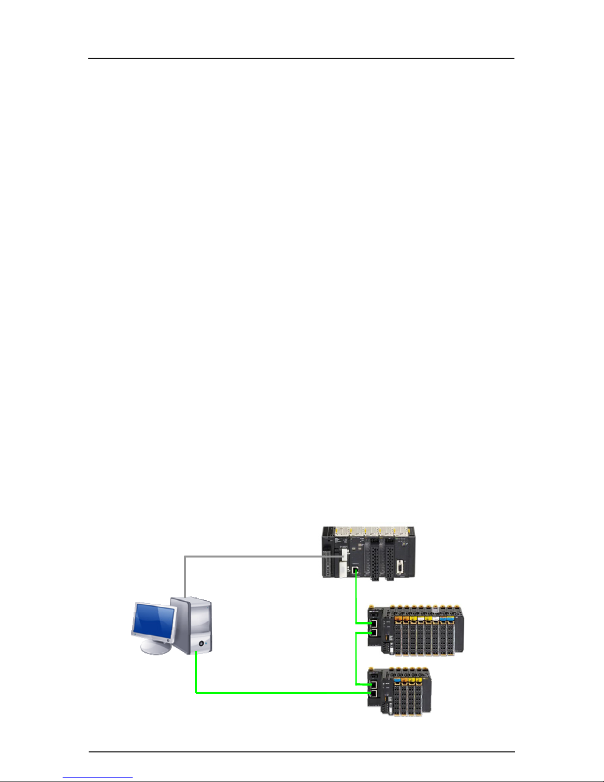
Connection of devices for configuration
To configure the I/O controller – use a serial or USB connection from PLC to PC.
To configure the I/O devices – connect a network cable to the last I/O device (in case of
GRT1-PNT).
Typical Initial Connection diagram
Serial for config
uration of IO Controller
Ethernet for configuration of IO Devices
Rev 1.01 1 of 8
Page 2
Profinet Quick Start Guide
Configuration outline
1. Create IO Table in Cx-Programmer (fo r new Cx1W-PNT21)
2. Create the network topology in Cx-Configurator FDT
3. Set ‘names’ in real IO Devices using Ethernet connection (Search Devices)
4. Set same names of IO Devices to IO Controller in network topolo gy
5. Download Configuration of IO Devices to IO Controller (via Serial connection)
6. Restart system to finish configuration (IO Controller connects to IO Devices)
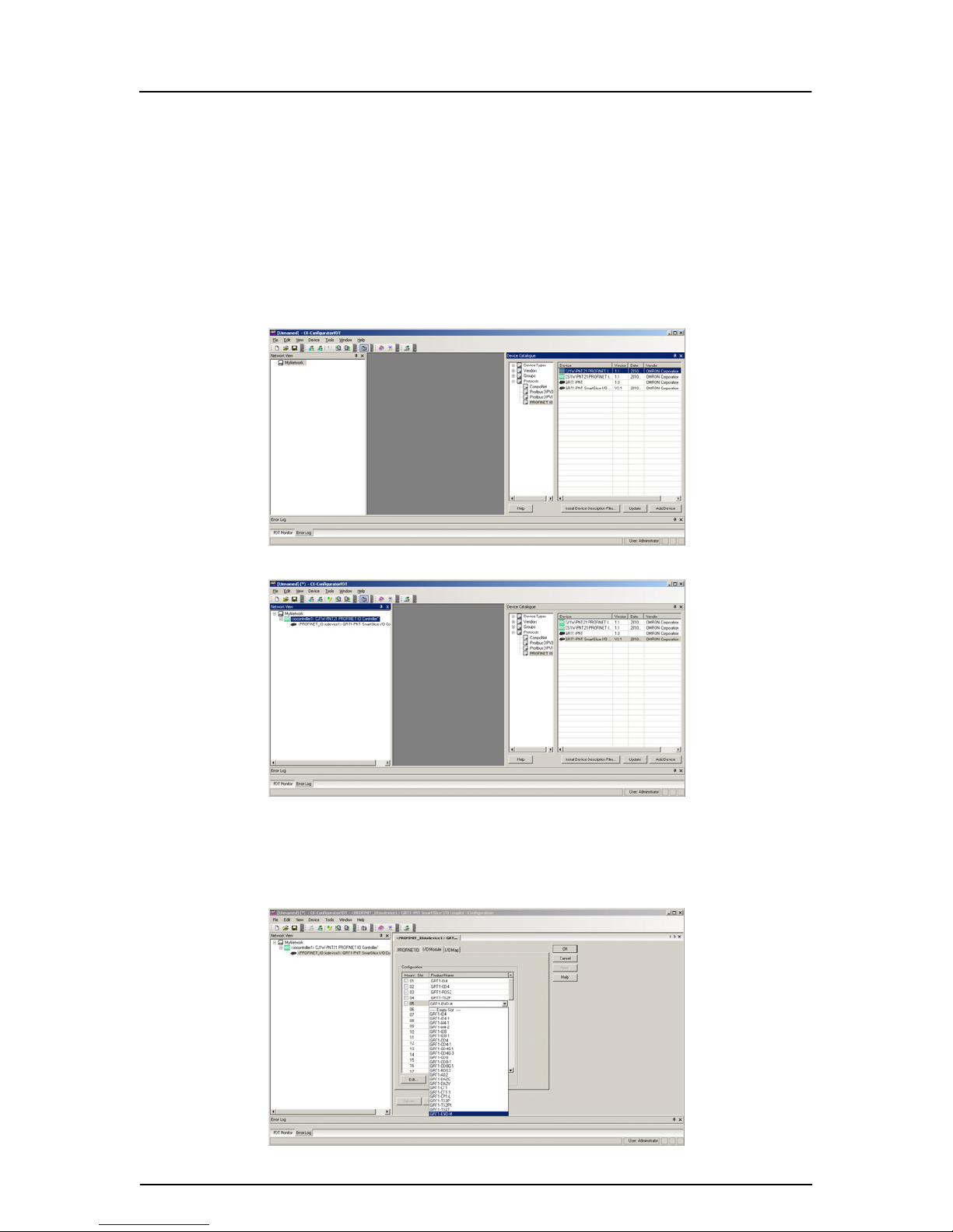
Create a network using Cx-Configurator FDT
Using Cx-Configurator FDT, open the Device Catalogue and show PROFINET IO. Highlight
PROFINET IO Controller (e.g. CJ1W-PNT21) and click ‘Add Device’.
Now add any IO Devices to the Controller (Controller must be highlighted in ‘MyNetwork’ tree).
Device Catalogue can be closed now.
Configure IO Device with correct set of IO Modules (Slices)
Double click on ‘iodevice1’ to configure the correct slices used in real system.
If GRT1-END-M is used, then this must be added as last slice – configuration error will occur if not.
Rev 1.01 2 of 8
Page 3
Profinet Quick Start Guide
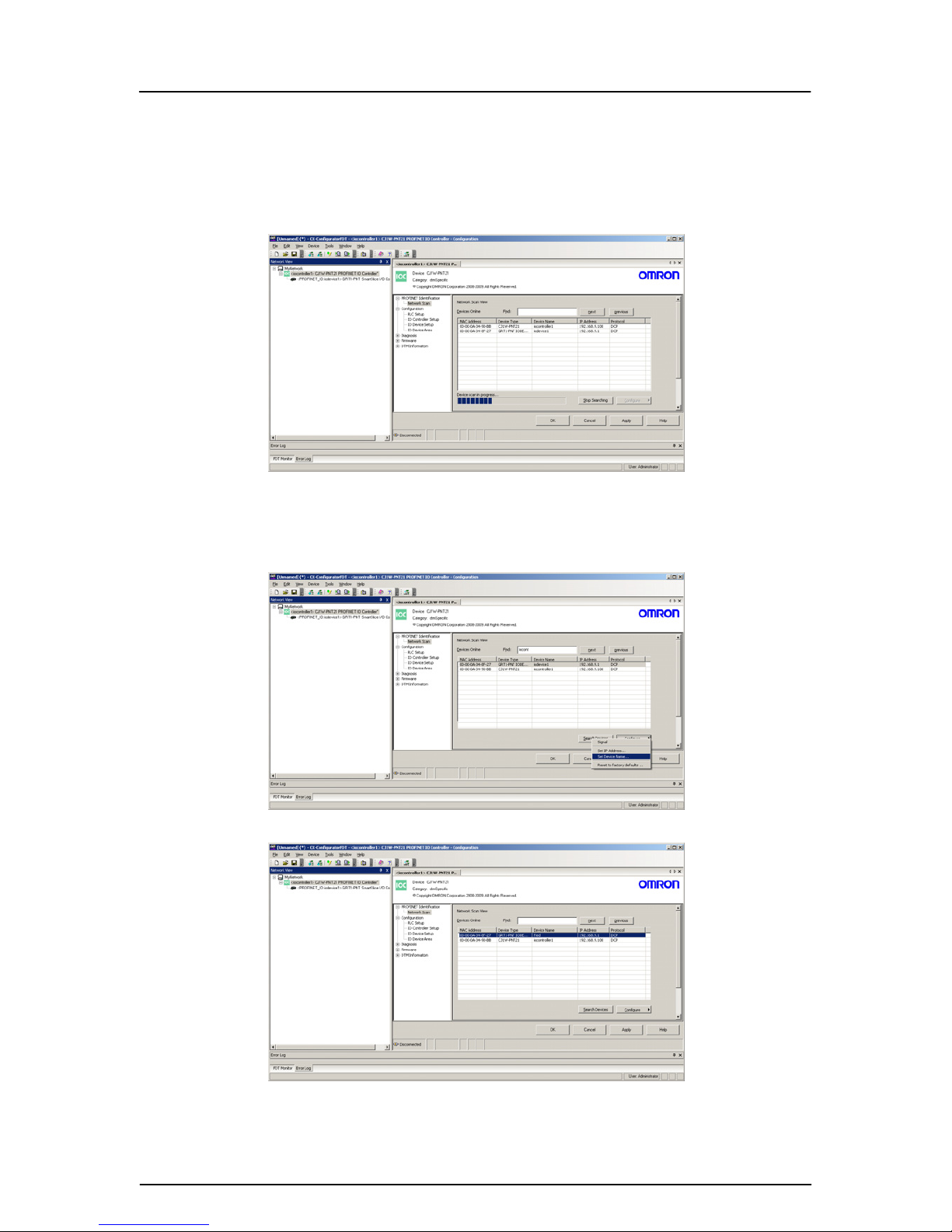
Configure IO Controller and IO Device ‘names’
Open the IO Controller in the ‘tree’ (double click) and initial screen will be ‘PROFINET Identification’.
First operation is to use ‘Network Scan’ to ‘find’ devices on the Ethernet network. This is done by
searching for MAC addresses (so IP does not need to be configured at this point).
Once all devices have been recognised, the IO devices now require unique ‘Device names’ set. Use
the ‘Configure’ button and ‘Set Device Name’ option to give each IO device a name. The name is
used by the IO Controller at boot time to confirm existence and then allow configuration by the IO
Controller (setting IP address, etc.).
For example the IO Device now has the name ‘fred’
Rev 1.01 3 of 8
Page 4

Profinet Quick Start Guide
Set up communication to PLC CPU by way of Serial/USB connection
Enter PLC type and communication settings using ‘Configure’. Enter the PROFINET unit number (set
on front of unit) and press ‘Test’.
The IO Controller will respond with data in ‘Unit Information’
The IO Controller Setup allows user to specify name and IP address for network (leave as defaults if
unsure).
IO Device Setup
The IO Device names must be changed to those set in the ‘Network Scan’. This allows the IO
Controller to make initial communication by ‘name’ (using ARP) and thereafter set the IP Address
(using DCP). Therefore change from….
Rev 1.01 4 of 8
Page 5

Profinet Quick Start Guide
to…
Saving configuration before download to IO Controller
When there is an ‘*’ displayed in Windows title or in network ‘tree’, then the configuration on the
‘screen’ does not match that stored on Disk. Before downloading Configuration changes to the IO
Controller, please make sure the project is saved (‘*’ disappear).
Download Configuration
Now the project (configuration) can be sent to the IO Controller.
Right Click on the IO Controller and select ‘Download Parameters to device’.
Rev 1.01 5 of 8
Page 6

Profinet Quick Start Guide
Once Parameters Downloaded, system requires restart. This is easily achieved by turning power off
and then on. Please make sure the IO Devices are powered on before the IO Controller (or at least at
the same time).
This should result in communication between IO Device(s) and IO Controller and hence cyclic IO
exchange.
Where is my data?
Data is mapped to/from PLC where IO Device configuration was set.
In this example, the input data from the Input devices will start at CIO 3300. Note that the PROFINET
Smart Slice bus coupler (GRT1-PNT) has IO allocated – to allow user to read Slice ‘status’.
Select the ‘Output Allocation’ tab for output IO.
Rev 1.01 6 of 8
Page 7

Profinet Quick Start Guide
Configuring individual Smart Slice parameters
To configure/setup parameters on individual Smart Slices (e.g. changing range on an Analogue input
from 0V-5V to 4mA-20mA), Cx-Configurator FDT must be connected to the Profinet using an Ethernet
connection (same connection to set ‘names’). It is not currently possible to use another
communication option (e.g. via USB on PLC CPU).
Once ‘on-line’, configuration data for Individual Smart Slices can be modified, compared and
uploaded.
Connection diagram for Smart Slice Parameter configuration
Ethernet to configure Smart Slices of IO Devices
The P
C running Cx-Configurator FDT must have a unique IP address set on the same network as the
Profinet. For example, if the PROFINET IO Controller is 192.168.9.100, PROFINET IO Device is
192.168.9.90, then set PC IP address to 192.168.9.20 (say).
Messages sent from Cx-Configurator FDT to the Smart Slice coupler are sent as FINS packets over
PROFINET/Ethernet.
In the project tree ‘open’ the Smart Slice component. Also right click on the same component in the
tree and ‘Work Online’. When connected, the buttons along the component will no longer be greyed
out.
Italic = online
Online = not greyed out
Rev 1.01 7 of 8
Page 8

Profinet Quick Start Guide
Rev 1.01 8 of 8
Use ‘Edit’ button to modify settings.
For example, to change the input range on ‘Smart Slice AD2’ from 0V-5V to 4mA-20mA
Once changes have been made, click ‘OK’ to close the Edit window. Use the ‘Download’ button to
transfer the new settings to the Smart Slice Coupler. The unit will usually require a ‘restart’ for the new
settings to take effect.
Hint – make a backup
Please keep a backup copy of the Cx-Co nfigurato r FDT file ( *.cpr). O nce config uration is downloaded
to the IO Controller, it is not possible to upload configuration ‘layout’ details. It is not possible to
connect with a ‘blank’ Cx-Configurator FDT network and upload devices that are connected to
resurrect Cx-Configurator FDT configuration.
Further Information
For more detailed information about PROFINET IO setup, configuration and operation please refer to
the relevant Omron manuals and support information:-
W12E-EN-xx CJ1W-PNT21 Operation Manual
W16E-EN-xx CS1W-PNT21 Operation Manual
W13E-EN-xx GRT1-PNT Operation Manual
Please use myOMRON.com to search for more PROFINET articles:For example …
http://www.myomron.com/modules/KB/file_d.php?id=109
Technote_Profinet
PROFINET Quick Start Guide
Revision 1.00 November 2010 Original document
Revision 1.01 December 2010 Addition of Smart Slice parameter setup via Ethernet
 Loading...