

Page 1
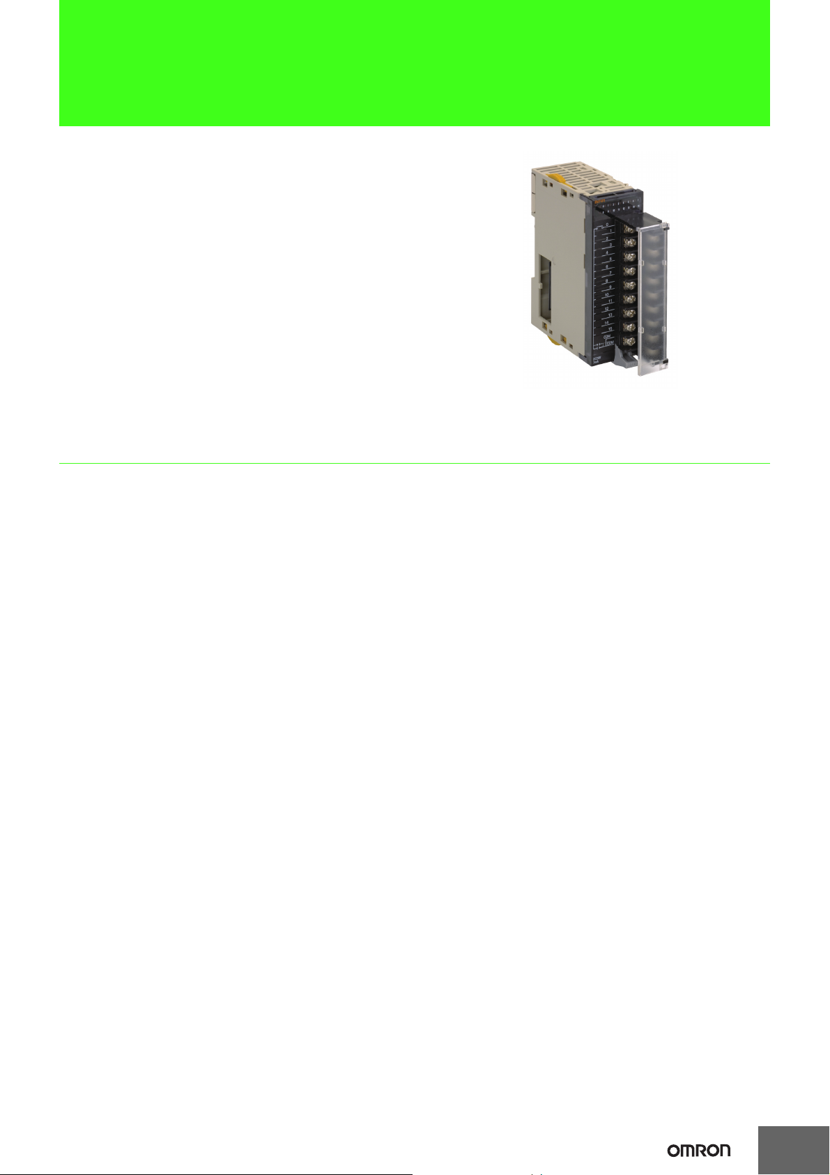
CJ-series Interrupt Input Units
CJ1W-INT01
CJ1W-INT01
High-speed Starting of I/O Interrupt
Tasks. Use Up to Two Units for a
Total of Up to 32 Interrupt Inputs.
• Receive inputs to start I/O interrupt tasks. When the
Interrupt Input Unit receives an input, the CPU Unit will
interrupt execution of the cyclic tasks in the normal
program and execute an I/O interrupt task.
CSM_CJ1W-INT01_DS_E_2_2
Features
• High-speed ON response of 0.05 ms
• Use up to 32 interrupt inputs with up to two Units per CPU Unit.
• Applicable with both NPN and PNP output devices. Polarity selection is not required. *
* The same polarity is used for the same common.
1
Page 2
CJ1W-INT01
Ordering Information
International Standards
• The standards are abbreviated as follows: U: UL, U1: UL (Class I Division 2 Products for Hazardous Locations), C: CSA, UC: cULus, UC1: cULus (Class I Division 2
Products for Hazardous Locations), CU: cUL, N: NK, L: Lloyd, and CE: EC Directives.
• Contact your OMRON representative for further details and applicable conditions for these standards.
Interrupt Input Units
Specifications
Input pulse
width
conditions
ON time:
0.05 ms max.
OFF time:
0.5 ms max.
Max. Units
mountable
per Unit
2
External
connection
Removable
terminal
block
No. of words
allocated
1 word 0.08 − CJ1W-INT01
Unit type
CJ1
Basic
I/O Units
Product
name
Interrupt
Input Unit
I/O
points
16
inputs
Input
voltage
current
24 VDC,
7 mA
Commons
16 points,
1 common
Note: 1. Can be used only on CPU Racks, and not on Expansion Racks.
2. The locations where the Units can be mounted depend on the CPU Rack and the CPU Unit model.
CJ2H-CPU6@-EIP: From the slot next to the CPU Unit until the fourth slot.
CJ1G, CJ1H: From the slot next to the CPU Unit until the fifth slot.
CJ1M: From the slot next to the CPU Unit until the third slot. (Final order entry date for CJ1M :The end of March, 2021)
3. With the SYSMAC NJ-series Controllers,Interrupt Input Units can be used as normal Basic Input Units. They cannot be used to start I/O
interrupt tasks.
Current
consumption
(A)
5 V 24 V
Model Standards
UC1, N, L,
CE
Accessories
There is no accessory for the CJ series Interrupt Input Units.
Mountable Racks
Molde
CJ1W-INT01 2 Units *1*4
*1. The Interrupt Input Unit can be mounted in slots 0 to 4 on the CJ1-CPU Rack. An Incorrect Unit/Expansion Rack Connection error will occur if
an Interrupt Input Unit is mounted to slot 5 or higher.
*2. Connectable slot position changes with the CPU Unit.
•CJ1M-CPU@@: Slot No.0 to 2
• CJ2H-CPU@@-EIP: Slot No.0 to 3
• CPU Unit other than abobe: Slot No.0 to 4
If the Unit is mounted to the slot other than abobe, I/O setting error will occur. (Final order entry date for CJ1M :The end of March, 2021)
*3. An I/O setting error will occur if an Interrupt Input Unit is mounted to an Expansion Rack.
*4. Interrupt Input Units can be used as normal Basic Input Units. They cannot be used to start I/O interrupt tasks.
NJ system CJ system (CJ1, CJ2) CP1H system NSJ system
CPU Rack
Expansion
Rack
Not supported
*3
CJ1-CPU
Rack
Not supported 2 Units *2
CPU Units
other than left
Expansion
Backplane
Not supported
*3
CP1H PLC NSJ Controller
Not supported Not supported
Expansion
Backplane
Not supported
*3
2
Page 3

Specifications
CJ1W-INT01 Interrupt Input Unit (16 Points)
Name 16-point Interrupt Input Unit with Terminal Block
Model CJ1W-INT01
Rated Input Voltage 24 VDC
Rated Input Voltage Range 20.4 to 26.4 VDC
Input Impedance 3.3 kΩ
Input Current 7 mA typical (at 24 VDC)
ON Voltage/ON Current 14.4 VDC min./3 mA min.
OFF Voltage/OFF Current 5 VDC max./1 mA max.
ON Response Time 0.05 ms max.
OFF Response Time 0.5 ms max.
Number of Circuits 16 (16 points/common, 1 circuit)
Number of Simultaneously
ON Points
Insulation Resistance 20 MΩ between external terminals and GR terminal (at 100 VDC)
DielectrQic Strength 1,000 VAC between external terminals and GR terminal for 1 minute at a leakage current of 10 mA max.
Internal Current Consumption
Weight 110 g max.
Accessories None
Circuit Configuration
External connection and
terminal-device variable
diagram
100% (16 points/common) simultaneously ON (24 VDC)
80 mA max.
Signal
name
Jxx_Ch1_In00
to
Jxx_Ch1_In15
COM
COM
Temperature characteristics for
simultaneously ON points
18
16
14
Input voltage: 26.4 VDC
12
10
8
6
4
2
Number of simultaneously ON points
0
0 10 20 30 40 50 60
3.3 kΩ
Ambient Temperature
Signal
name
Jxx_Ch1_In00
Jxx_Ch1_In02
Jxx_Ch1_In04
Jxx_Ch1_In06
Jxx_Ch1_In08
Jxx_Ch1_In10
Jxx_Ch1_In12
Jxx_Ch1_In14
COM
1000 pF
A0
A1
A2
A3
A4
A5
A6
A7
A8
470 Ω
Input indicator
16 points at 45°C
12 points at 55°C
(°C)
Connector pin
*
B0
B1
B2
B3
B4
B5
B6
B7
B8
Signal
name
Jxx_Ch1_In01
Jxx_Ch1_In03
Jxx_Ch1_In05
Jxx_Ch1_In07
Jxx_Ch1_In09
Jxx_Ch1_In11
Jxx_Ch1_In13
Jxx_Ch1_In15
COM
• Up to two Interrupt Input Units can be mounted to the CPU
Rack. They must be connected as one of the five Units
immediately next to the CPU Unit. If an Interrupt Input Unit is
connected in any other position, an Incorrect Unit/Expansion
Rack Connection error will occur.
Internal circuits
• Set the pulse width of signals input to the Interrupt Input Unit so
they satisfy the following conditions.
• The signal names of the terminals are the device variable
names.
The device variable names are the names that use "Jxx" as the
device name.
OFF
0.5 ms min.
ON
0.05 ms min.
24 VDC
CJ1W-INT01
\
• The polarity can be connected in either direction.
• The signal names of the terminals are the device variable names. The device variable names are the names that use "Jxx" as the
device name.
Note: With NJ-series Controllers, Interrupt Input Units can be used as normal Basic Input Units.
They cannot be used to start I/O interrupt tasks.
* Terminal numbers A0 to A8 and B0 to B8 are used in the external connection and terminal-device variable diagrams. They are not printed on the Units.
3
Page 4

External Interface
Model number label
Input indicators
Terminal block for
Input wiring, 18P × 1
ERR
Wiring Terminal Blocks
Electric Wires
The following wire gauges are recommended.
Terminal Block Connector Wire Size
18-terminal AWG 22 to 18 (0.32 to 0.82 mm
Connector
Connect to the connector on the next Unit.
0 1 2 3 4 5 6 7
8 9 10 11 12 13 14 15
CJ1W-INT01
2
)
Crimp terminals
Use crimp terminals (M3) having the dimensions shown below.
6.2 mm max.
6.2 mm max.
4
Page 5

CJ1W-INT01
Dimensions (Unit: mm)
89
2.7
90
2.7
ID211
01234567
8 9
10 11 12 13 14 15
0
1
2
3
4
5
6
7
8
9
10
11
12
13
14
15
COM
COM
DC24V
7mA
31
65
Related Manuals
Name Cat. No. Contents
CJ-series
CJ2H-CPU6@-EIP, CJ2H-CPU6@, CJ2M-CPU@@
CJ2 CPU Unit Hardware User's Manual
CJ Series
CJ1H-CPU@@H-R, CJ1G/H-CPU@@H, CJ1G-CPU@@P,
CJ1G-CPU@@, CJ1M-CPU@@
Programmable Controllers Operation Manual
NJ-series CPU Unit Hardware User's Manual
NJ501-@@@@
W472
W393
W500
Describes the following for CJ2 CPU Units:
• Overview and features
• Basic system configuration
• Part nomenclature and functions
• Mounting and setting procedure
• Remedies for errors
• Also refer to the Software User's Manual (W473).
Provides an outlines of and describes the design, installation, maintenance, and
other basic operations for the CJ-series PLCs.
An introduction to the entire NJ-series system is provided along with the following
information on a Controller built with an NJ501 CPU Unit.
• Features and system configuration
• Introduction
• Part names and functions
• General specifications
• Installation and wiring
• Maintenance and inspection
Use this manual together with the NJ-series CPU Unit Software User's Manual
(Cat. No. W501).
5
Page 6

Terms and Conditions Agreement
Read and understand this catalog.
Please read and understand this catalog before purchasing the products. Please consult your OMRON representative if you
have any questions or comments.
Warranties.
(a) Exclusive Warranty. Omron’s exclusive warranty is that the Products will be free from defects in materials and workmanship
for a period of twelve months from the date of sale by Omron (or such other period expressed in writing by Omron). Omron
disclaims all other warranties, express or implied.
(b) Limitations. OMRON MAKES NO WARRANTY OR REPRESENTATION, EXPRESS OR IMPLIED, ABOUT
NON-INFRINGEMENT, MERCHANTABILITY OR FITNESS FOR A PARTICULAR PURPOSE OF THE PRODUCTS. BUYER
ACKNOWLEDGES THAT IT ALONE HAS DETERMINED THAT THE
PRODUCTS WILL SUITABLY MEET THE REQUIREMENTS OF THEIR INTENDED USE.
Omron further disclaims all warranties and responsibility of any type for claims or expenses based on infringement by the
Products or otherwise of any intellectual property right. (c) Buyer Remedy. Omron’s sole obligation hereunder shall be, at
Omron’s election, to (i) replace (in the form originally shipped with Buyer responsible for labor charges for removal or
replacement thereof) the non-complying Product, (ii) repair the non-complying Product, or (iii) repay or credit Buyer an amount
equal to the purchase price of the non-complying Product; provided that in no event shall Omron be responsible for warranty,
repair, indemnity or any other claims or expenses regarding the Products unless Omron’s analysis confirms that the Products
were properly handled, stored, installed and maintained and not subject to contamination, abuse, misuse or inappropriate
modification. Return of any Products by Buyer must be approved in writing by Omron before shipment. Omron Companies shall
not be liable for the suitability or unsuitability or the results from the use of Products in combination with any electrical or
electronic components, circuits, system assemblies or any other materials or substances or environments. Any advice,
recommendations or information given orally or in writing, are not to be construed as an amendment or addition to the above
warranty.
See http://www.omron.com/global/ or contact your Omron representative for published information.
Limitation on Liability; Etc.
OMRON COMPANIES SHALL NOT BE LIABLE FOR SPECIAL, INDIRECT, INCIDENTAL, OR CONSEQUENTIAL DAMAGES,
LOSS OF PROFITS OR PRODUCTION OR COMMERCIAL LOSS IN ANY WAY CONNECTED WITH THE PRODUCTS,
WHETHER SUCH CLAIM IS BASED IN CONTRACT, WARRANTY, NEGLIGENCE OR STRICT LIABILITY.
Further, in no event shall liability of Omron Companies exceed the individual price of the Product on which liability is asserted.
Suitability of Use.
Omron Companies shall not be responsible for conformity with any standards, codes or regulations which apply to the
combination of the Product in the Buyer’s application or use of the Product. At Buyer’s request, Omron will provide applicable
third party certification documents identifying ratings and limitations of use which apply to the Product. This information by itself
is not sufficient for a complete determination of the suitability of the Product in combination with the end product, machine,
system, or other application or use. Buyer shall be solely responsible for determining appropriateness of the particular Product
with respect to Buyer’s application, product or system. Buyer shall take application responsibility in all cases.
NEVER USE THE PRODUCT FOR AN APPLICATION INVOLVING SERIOUS RISK TO LIFE OR PROPERTY OR IN LARGE
QUANTITIES WITHOUT ENSURING THAT THE SYSTEM AS A WHOLE HAS BEEN DESIGNED TO ADDRESS THE RISKS,
AND THAT THE OMRON PRODUCT(S) IS PROPERLY RATED AND INSTALLED FOR THE INTENDED USE WITHIN THE
OVERALL EQUIPMENT OR SYSTEM.
Programmable Products.
Omron Companies shall not be responsible for the user’s programming of a programmable Product, or any consequence
thereof.
Performance Data.
Data presented in Omron Company websites, catalogs and other materials is provided as a guide for the user in determining
suitability and does not constitute a warranty. It may represent the result of Omron’s test conditions, and the user must correlate
it to actual application requirements. Actual performance is subject to the Omron’s Warranty and Limitations of Liability.
Change in Specifications.
Product specifications and accessories may be changed at any time based on improvements and other reasons. It is our
practice to change part numbers when published ratings or features are changed, or when significant construction changes are
made. However, some specifications of the Product may be changed without any notice. When in doubt, special part numbers
may be assigned to fix or establish key specifications for your application. Please consult with your Omron’s representative at
any time to confirm actual specifications of purchased Product.
Errors and Omissions.
Information presented by Omron Companies has been checked and is believed to be accurate; however, no responsibility is
assumed for clerical, typographical or proofreading errors or omissions.
2021.3
OMRON Corporation
Industrial Automation Company
http://www.ia.omron.com/
In the interest of product improvement, specifications are subject to change without notice.
(c)Copyright OMRON Corporation 2021 All Right Reserved.
 Loading...