

Page 1

Cat. No. W440-E1-03
SYSMAC
CS/CJ Series
CS1W-FLN22 (100Base-TX)
CJ1W-FLN22 (100Base-TX)
FL-net Units
OPERATION MANUAL
Page 2

Page 3

CS1W-FLN22 (100Base-TX)
CJ1W-FLN22 (100Base-TX)
FL-net Units
Operation Manual
Revised October 2010
Page 4

iv
Page 5

Notice:
r
f
OMRON products are manufactured for use according to proper procedures by a qualified operator
and only for the purposes described in this manual.
The following conventions are used to indicate and classify precautions in this manual. Always heed
the information provided with them. Failure to heed precautions can result in injury to people or damage to property.
!DANGER Indicates an imminently hazardous situation which, if not avoided, will result in death or
serious injury. Additionally, there may be severe property damage.
!WARNING Indicates a potentially hazardous situation which, if not avoided, could result in death or
serious injury. Additionally, there may be severe property damage.
!Caution Indicates a potentially hazardous situation which, if not avoided, may result in minor or
moderate injury, or property damage.
OMRON Product References
All OMRON products are capitalized in this manual. The word “Unit” is also capitalized when it refers to
an OMRON product, regardless of whether or not it appears in the proper name of the product.
The abbreviation “Ch,” which appears in some displays and on some OMRON products, often means
“word” and is abbreviated “Wd” in documentation in this sense.
The abbreviation “PLC” means Programmable Controller.
Visual Aids
The following headings appear in the left column of the manual to help you locate different types of
information.
OMRON, 2004
All rights reserved. No part of this publication may be reproduced, stored in a retrieval system, or transmitted, in any form, o
by any means, mechanical, electronic, photocopying, recording, or otherwise, without the prior written permission o
OMRON.
No patent liability is assumed with respect to the use of the information contained herein. Moreover, because OMRON is constantly striving to improve its high-quality products, the information contained in this manual is subject to change without
notice. Every precaution has been taken in the preparation of this manual. Nevertheless, OMRON assumes no responsibility
for errors or omissions. Neither is any liability assumed for damages resulting from the use of the information contained in
this publication.
Note Indicates information of particular interest for efficient and convenient opera-
tion of the product.
1,2,3... 1. Indicates lists of one sort or another, such as procedures, checklists, etc.
v
Page 6

vi
Page 7

TABLE OF CONTENTS
PRECAUTIONS . . . . . . . . . . . . . . . . . . . . . . . . . . . . . . . . . . . xix
1 Intended Audience . . . . . . . . . . . . . . . . . . . . . . . . . . . . . . . . . . . . . . . . . . . . . . . . . . . . . . . . xx
2 General Precautions . . . . . . . . . . . . . . . . . . . . . . . . . . . . . . . . . . . . . . . . . . . . . . . . . . . . . . . xx
3 Safety Precautions. . . . . . . . . . . . . . . . . . . . . . . . . . . . . . . . . . . . . . . . . . . . . . . . . . . . . . . . . xx
4 Operating Environment Precautions . . . . . . . . . . . . . . . . . . . . . . . . . . . . . . . . . . . . . . . . . . . xxi
5 Application Precautions . . . . . . . . . . . . . . . . . . . . . . . . . . . . . . . . . . . . . . . . . . . . . . . . . . . .xxi
6 Conformance to EC Directives . . . . . . . . . . . . . . . . . . . . . . . . . . . . . . . . . . . . . . . . . . . . . . . xxiii
7 Unit Versions of CS/CJ-series FL-net Units . . . . . . . . . . . . . . . . . . . . . . . . . . . . . . . . . . . . . xxiv
SECTION 1
Features and System Configuration . . . . . . . . . . . . . . . . . . . 1
1-1 FL-net Overview . . . . . . . . . . . . . . . . . . . . . . . . . . . . . . . . . . . . . . . . . . . . . . . . . . . . . . . . . . 2
1-2 System Configuration . . . . . . . . . . . . . . . . . . . . . . . . . . . . . . . . . . . . . . . . . . . . . . . . . . . . . . 7
1-3 Related Programming Devices . . . . . . . . . . . . . . . . . . . . . . . . . . . . . . . . . . . . . . . . . . . . . . . 8
1-4 Introducing the CX-FLnet Support Software . . . . . . . . . . . . . . . . . . . . . . . . . . . . . . . . . . . . 8
1-5 Specifications . . . . . . . . . . . . . . . . . . . . . . . . . . . . . . . . . . . . . . . . . . . . . . . . . . . . . . . . . . . . 9
1-6 Precautions . . . . . . . . . . . . . . . . . . . . . . . . . . . . . . . . . . . . . . . . . . . . . . . . . . . . . . . . . . . . . . 13
SECTION 2
Communications Functions . . . . . . . . . . . . . . . . . . . . . . . . . . 15
2-1 FL-net . . . . . . . . . . . . . . . . . . . . . . . . . . . . . . . . . . . . . . . . . . . . . . . . . . . . . . . . . . . . . . . . . . 16
2-2 Cyclic Transmission . . . . . . . . . . . . . . . . . . . . . . . . . . . . . . . . . . . . . . . . . . . . . . . . . . . . . . . 20
2-3 Message Transmission . . . . . . . . . . . . . . . . . . . . . . . . . . . . . . . . . . . . . . . . . . . . . . . . . . . . .21
2-4 FINS Communications Service. . . . . . . . . . . . . . . . . . . . . . . . . . . . . . . . . . . . . . . . . . . . . . . 22
SECTION 3
Startup Procedure . . . . . . . . . . . . . . . . . . . . . . . . . . . . . . . . . 25
3-1 Before Operation. . . . . . . . . . . . . . . . . . . . . . . . . . . . . . . . . . . . . . . . . . . . . . . . . . . . . . . . . . 26
3-2 Initial Setup . . . . . . . . . . . . . . . . . . . . . . . . . . . . . . . . . . . . . . . . . . . . . . . . . . . . . . . . . . . . . . 27
3-3 Nomenclature and Functions . . . . . . . . . . . . . . . . . . . . . . . . . . . . . . . . . . . . . . . . . . . . . . . . 28
3-4 Hardware Setup. . . . . . . . . . . . . . . . . . . . . . . . . . . . . . . . . . . . . . . . . . . . . . . . . . . . . . . . . . . 30
3-5 Mounting to the PLC. . . . . . . . . . . . . . . . . . . . . . . . . . . . . . . . . . . . . . . . . . . . . . . . . . . . . . . 33
3-6 Network Installation . . . . . . . . . . . . . . . . . . . . . . . . . . . . . . . . . . . . . . . . . . . . . . . . . . . . . . . 34
3-7 Connecting to the Network . . . . . . . . . . . . . . . . . . . . . . . . . . . . . . . . . . . . . . . . . . . . . . . . . . 38
3-8 Creating an I/O Table . . . . . . . . . . . . . . . . . . . . . . . . . . . . . . . . . . . . . . . . . . . . . . . . . . . . . . 39
3-9 Creating Routing Tables . . . . . . . . . . . . . . . . . . . . . . . . . . . . . . . . . . . . . . . . . . . . . . . . . . . . 40
3-10 System Setup. . . . . . . . . . . . . . . . . . . . . . . . . . . . . . . . . . . . . . . . . . . . . . . . . . . . . . . . . . . . . 45
3-11 Checking Communications . . . . . . . . . . . . . . . . . . . . . . . . . . . . . . . . . . . . . . . . . . . . . . . . . . 46
vii
Page 8

TABLE OF CONTENTS
SECTION 4
System Setup and Memory Allocations . . . . . . . . . . . . . . . . 47
4-1 Allocated Words . . . . . . . . . . . . . . . . . . . . . . . . . . . . . . . . . . . . . . . . . . . . . . . . . . . . . . . . . . 48
4-2 CPU Bus Unit System Setup. . . . . . . . . . . . . . . . . . . . . . . . . . . . . . . . . . . . . . . . . . . . . . . . . 49
4-3 Allocated Words in the CIO Area . . . . . . . . . . . . . . . . . . . . . . . . . . . . . . . . . . . . . . . . . . . . . 51
4-4 Allocated Words in the DM Area . . . . . . . . . . . . . . . . . . . . . . . . . . . . . . . . . . . . . . . . . . . . . 58
SECTION 5
Data Link. . . . . . . . . . . . . . . . . . . . . . . . . . . . . . . . . . . . . . . . . 63
5-1 Data Link Overview . . . . . . . . . . . . . . . . . . . . . . . . . . . . . . . . . . . . . . . . . . . . . . . . . . . . . . . 64
5-2 Setting Data Link Tables. . . . . . . . . . . . . . . . . . . . . . . . . . . . . . . . . . . . . . . . . . . . . . . . . . . . 68
SECTION 6
Message Transmission . . . . . . . . . . . . . . . . . . . . . . . . . . . . . . 83
6-1 Message Transmission . . . . . . . . . . . . . . . . . . . . . . . . . . . . . . . . . . . . . . . . . . . . . . . . . . . . .84
6-2 Details of Supported Messages . . . . . . . . . . . . . . . . . . . . . . . . . . . . . . . . . . . . . . . . . . . . . . . 86
SECTION 7
FINS Communications. . . . . . . . . . . . . . . . . . . . . . . . . . . . . . 91
7-1 Overview of FINS Communications. . . . . . . . . . . . . . . . . . . . . . . . . . . . . . . . . . . . . . . . . . . 92
7-2 Sending Commands from a PLC . . . . . . . . . . . . . . . . . . . . . . . . . . . . . . . . . . . . . . . . . . . . . 94
7-3 Command Codes and Response Codes. . . . . . . . . . . . . . . . . . . . . . . . . . . . . . . . . . . . . . . . . 105
7-4 CS/CJ-series Memory Areas and Virtual Addresses. . . . . . . . . . . . . . . . . . . . . . . . . . . . . . . 106
7-5 Command/Response Reference . . . . . . . . . . . . . . . . . . . . . . . . . . . . . . . . . . . . . . . . . . . . . . 107
SECTION 8
Communications Timing . . . . . . . . . . . . . . . . . . . . . . . . . . . . 133
8-1 Network Communications System . . . . . . . . . . . . . . . . . . . . . . . . . . . . . . . . . . . . . . . . . . . . 134
8-2 Communications Cycle Time . . . . . . . . . . . . . . . . . . . . . . . . . . . . . . . . . . . . . . . . . . . . . . . . 134
8-3 Influence on Cycle Time. . . . . . . . . . . . . . . . . . . . . . . . . . . . . . . . . . . . . . . . . . . . . . . . . . . .136
8-4 Calculating the Data Link I/O Response Time . . . . . . . . . . . . . . . . . . . . . . . . . . . . . . . . . . . 136
8-5 Message Service Transmission Delays . . . . . . . . . . . . . . . . . . . . . . . . . . . . . . . . . . . . . . . . . 137
SECTION 9
Testing Communications . . . . . . . . . . . . . . . . . . . . . . . . . . . . 139
9-1 Communications Testing Functions . . . . . . . . . . . . . . . . . . . . . . . . . . . . . . . . . . . . . . . . . . . 140
9-2 PING Command . . . . . . . . . . . . . . . . . . . . . . . . . . . . . . . . . . . . . . . . . . . . . . . . . . . . . . . . . . 140
9-3 Internode Test . . . . . . . . . . . . . . . . . . . . . . . . . . . . . . . . . . . . . . . . . . . . . . . . . . . . . . . . . . . . 141
viii
Page 9

TABLE OF CONTENTS
SECTION 10
Troubleshooting . . . . . . . . . . . . . . . . . . . . . . . . . . . . . . . . . . . 145
10-1 Troubleshooting with Indicators . . . . . . . . . . . . . . . . . . . . . . . . . . . . . . . . . . . . . . . . . . . . . . 146
10-2 Error Status . . . . . . . . . . . . . . . . . . . . . . . . . . . . . . . . . . . . . . . . . . . . . . . . . . . . . . . . . . . . . . 148
10-3 Error Log. . . . . . . . . . . . . . . . . . . . . . . . . . . . . . . . . . . . . . . . . . . . . . . . . . . . . . . . . . . . . . . . 149
10-4 Troubleshooting Procedures . . . . . . . . . . . . . . . . . . . . . . . . . . . . . . . . . . . . . . . . . . . . . . . . .152
10-5 Maintenance . . . . . . . . . . . . . . . . . . . . . . . . . . . . . . . . . . . . . . . . . . . . . . . . . . . . . . . . . . . . . 161
10-6 Inspections . . . . . . . . . . . . . . . . . . . . . . . . . . . . . . . . . . . . . . . . . . . . . . . . . . . . . . . . . . . . . . 162
SECTION 11
CX-FLnet Support Software Operations . . . . . . . . . . . . . . . 167
11-1 CX-FLnet . . . . . . . . . . . . . . . . . . . . . . . . . . . . . . . . . . . . . . . . . . . . . . . . . . . . . . . . . . . . . . . 168
11-2 Operating Procedures . . . . . . . . . . . . . . . . . . . . . . . . . . . . . . . . . . . . . . . . . . . . . . . . . . . . . . 170
Appendices
A System Configuration . . . . . . . . . . . . . . . . . . . . . . . . . . . . . . . . . . . . . . . . . . . . . . . . . . . . . .189
B System Configuration Example . . . . . . . . . . . . . . . . . . . . . . . . . . . . . . . . . . . . . . . . . . . . . . 193
C Network System Definitions . . . . . . . . . . . . . . . . . . . . . . . . . . . . . . . . . . . . . . . . . . . . . . . . 199
D FL-net Network Control . . . . . . . . . . . . . . . . . . . . . . . . . . . . . . . . . . . . . . . . . . . . . . . . . . . . 205
E FL-net Profile . . . . . . . . . . . . . . . . . . . . . . . . . . . . . . . . . . . . . . . . . . . . . . . . . . . . . . . . . . . . 211
F FL-net Unit Support Software Ver. 1.6 . . . . . . . . . . . . . . . . . . . . . . . . . . . . . . . . . . . . . . . . 221
G International System of Units . . . . . . . . . . . . . . . . . . . . . . . . . . . . . . . . . . . . . . . . . . . . . . . 245
Revision History . . . . . . . . . . . . . . . . . . . . . . . . . . . . . . . . . . . 251
ix
Page 10

Page 11

About this Manual:
This manual describes the installation and operation of the CS1W-FLN22 (100Base-TX) and CJ1WFLN22 (100Base-TX) FL-net Units.
FL-net Units are used to connect to FL-net networks.
Please read this manual and all related manuals listed in the following table carefully and be sure you
understand the information provided before attempting to install and operate an FL-net Unit.
Name Cat. No. Contents
SYSMAC CS/CJ Series
CS1W-FLN22 (100Base-TX) and CJ1W-FLN22
(100Base-TX) FL-net Units
Operation Manual
(this manual)
SYSMAC CS/CJ Series
CS1W-ETN21, CJ1W-ETN21
100Base-TX Ethernet Units
Operation Manual, Construction of Network
CXONE-AL@@C-E
CX-One FA Integrated Tool Package Setup Manual
WS02-CXPC1-E-V61
SYSMAC CX-Programmer Ver. 6.1
Operation Manual
WS02-CXPC1-E-V61
SYSMAC CX-Programmer Ver. 6.1
Operation Manual Function Blocks
CXONE-AL@@C-E
CX-Integrator Operation Manual
SYSMAC CS Series
CS1G/H-CPU@@-EV1, CS1G/H-CPU@@H
Programmable Controllers Operation Manual
SYSMAC CJ Series
CJ1G-CPU@@, CJ1M-CPU@@, CJ1G-CPU@@P,
CJ1G/H-CPU@@H
Programmable Controllers Operation Manual
SYSMAC CS/CJ Series
CS1G/H-CPU@@-EV1, CS1G/H-CPU@@H,
CS1D-CPU@@H, CS1D-CPU@@S, CJ1GCPU@@, CJ1M-CPU@@, CJ1G-CPU@@P, C J 1G /
H-CPU@@H
Programmable Controllers Programming Manual
W440 Describes the installation and operation of the CS1W-
FLN22 and CJ1W-FLN22 FL-net Units.
Refer to the Communications Commands Reference
Manual (W342) for information on FINS commands that
can be addressed to CS/CJ-series CPU Units.
W420 Provides information on operating and installing
100Base-TX Ethernet Units, including details on basic
settings and FINS communications.
W444 Provides an overview of the CX-One FA Integrated Tool
and installation procedures.
W446 Provides information on installing and operating the CX-
Programmer for all functions except for function blocks.
W447 Provides specifications and operating procedures for
function blocks.
When programming, refer to the CJ Series (W339) or CJ
Series (W393) Programmable Controllers Operation
Manual, CS/CJ Series Programmable Controllers Programming Manual (W394), and CS/CJ Series Programmable Controllers Instructions Reference Manual
(W340).
W445 Describes CX-Integrator operating procedures and pro-
vides information on network configuration (data links,
routing tables, Communications Units setup, etc.
W339 Provides an outline of and describes the features, sys-
tem configuration, installation, wiring, I/O memory allocations, and troubleshooting for the CS-series PLCs.
Use this manual together with the CS/CJ Series Pro-
grammable Controllers Programming Manual (W394).
W393 Provides an outline of and describes the features, sys-
tem configuration, installation, wiring, I/O memory allocations, and troubleshooting for the CJ-series PLCs.
Use this manual together with the CS/CJ Series Pro-
grammable Controllers Programming Manual (W394).
W394 This manual describes programming, tasks, file memory
function, and other functions of the CS/CJ-series PLCs.
Use this manual together with the CJ Series (W339) or
CJ Series (W393) Programmable Controllers Operation
Manual.
xi
Page 12

Name Cat. No. Contents
SYSMAC CS/CJ Series
CS1G/H-CPU@@-EV1, CS1G/H-CPU@@H,
CS1D-CPU@@H, CS1D-CPU@@S, CJ1GCPU@@, CJ1M-CPU@@, CJ1G-CPU@@P, C J 1G /
H-CPU@@H
Programmable Controllers Instructions Reference
Manual
SYSMAC CS/CJ Series
CS1G/H-CPU@@-EV1, CS1G/H-CPU@@H,
CS1D-CPU@@H, CS1D-CPU@@S, CJ1MCPU@@, CJ1G-CPU@@, CJ1G-CPU@@P, C J 1G /
H-CPU@@H, CS1W-SCB21-V1/41-V1, CS1WSCU21-V1, CJ1W-SCU21-V1/41-V1
Communications Commands Reference Manual
W340 Describes the ladder diagram programming instructions
supported by CS/CJ-series PLCs.
Use this manual together with the CJ Series (W339) or
CJ Series (W393) Programmable Controllers Operation
Manual and the CS/CJ Series Programmable Controllers Programming Manual (W394).
W342 Describes the C-series (Host Link) and FINS communi-
cations commands used with CS/CJ-series PLCs.
This manual describes communications commands
addressed to the CPU Unit. The communications path is
not relevant, i.e., communications can be performed via
a serial port on the CPU Unit, Serial Communications
Unit/Board, or a Communications Unit.
xii
Page 13

About this Manual, Continued
This manual contains the following sections.
Section 1 introduces the overall structure of an FL-net (Ver. 2.00) network, outlines the features of the
FL-net (Ver. 2.00) Unit, describes the communications protocols used by an FL-net (Ver. 2.00) network, and provides basic precautions for use of the network.
Section 2 describes the communications functions that can be used with the FL-net (Ver. 2.00) Units.
Section 3 explains the procedure for starting up the FL-net (Ver. 2.00) Unit, including mounting to the
PLC, making the required settings, and checking communications.
Section 4 explains the System Setup and the words allocated in the CIO Area and the DM Area for
FL-net (Ver. 2.00) Units.
Section 5 explains the Data Link function, including an overview and examples of how to make the
required settings.
Section 6 describes the message transmission used by an FL-net (Ver. 2.00) network.
Section 7 provides information on communicating on FL-net Systems and interconnected networks
using FINS commands. The information provided in the section deals only with FINS communications
in reference to FL-net (Ver. 2.00) Units.
Section 8 describes the communications system, communications cycle time, communications cycle
time calculation, data link I/O response time, data link I/O response time calculation, and message service transmission delays.
Section 9 describes functions that allow you to test communications.
Section 10 describes information and procedures that can be used to troubleshoot problems that
sometimes occur with FL-net (Ver. 2.00) Unit and FL-net communications.
Section 11 describes the Support Software used to make settings for the FL-net Units.
!WARNING Failure to read and understand the information provided in this manual may result in per-
sonal injury or death, damage to the product, or product failure. Please read each section
in its entirety and be sure you understand the information provided in the section and
related sections before attempting any of the procedures or operations given.
xiii
Page 14

xiv
Page 15

Read and Understand this Manual
Please read and understand this manual before using the product. Please consult your OMRON
representative if you have any questions or comments.
Warranty and Limitations of Liability
WARRANTY
OMRON's exclusive warranty is that the products are free from defects in materials and workmanship for a
period of one year (or other period if specified) from date of sale by OMRON.
OMRON MAKES NO WARRANTY OR REPRESENTATION, EXPRESS OR IMPLIED, REGARDING NONINFRINGEMENT, MERCHANTABILITY, OR FITNESS FOR PARTICULAR PURPOSE OF THE
PRODUCTS. ANY BUYER OR USER ACKNOWLEDGES THAT THE BUYER OR USER ALONE HAS
DETERMINED THAT THE PRODUCTS WILL SUITABLY MEET THE REQUIREMENTS OF THEIR
INTENDED USE. OMRON DISCLAIMS ALL OTHER WARRANTIES, EXPRESS OR IMPLIED.
LIMITATIONS OF LIABILITY
OMRON SHALL NOT BE RESPONSIBLE FOR SPECIAL, INDIRECT, OR CONSEQUENTIAL DAMAGES,
LOSS OF PROFITS OR COMMERCIAL LOSS IN ANY WAY CONNECTED WITH THE PRODUCTS,
WHETHER SUCH CLAIM IS BASED ON CONTRACT, WARRANTY, NEGLIGENCE, OR STRICT
LIABILITY.
In no event shall the responsibility of OMRON for any act exceed the individual price of the product on which
liability is asserted.
IN NO EVENT SHALL OMRON BE RESPONSIBLE FOR WARRANTY, REPAIR, OR OTHER CLAIMS
REGARDING THE PRODUCTS UNLESS OMRON'S ANALYSIS CONFIRMS THAT THE PRODUCTS
WERE PROPERLY HANDLED, STORED, INSTALLED, AND MAINTAINED AND NOT SUBJECT TO
CONTAMINATION, ABUSE, MISUSE, OR INAPPROPRIATE MODIFICATION OR REPAIR.
xv
Page 16

Application Considerations
SUITABILITY FOR USE
OMRON shall not be responsible for conformity with any standards, codes, or regulations that apply to the
combination of products in the customer's application or use of the products.
At the customer's request, OMRON will provide applicable third party certification documents identifying
ratings and limitations of use that apply to the products. This information by itself is not sufficient for a
complete determination of the suitability of the products in combination with the end product, machine,
system, or other application or use.
The following are some examples of applications for which particular attention must be given. This is not
intended to be an exhaustive list of all possible uses of the products, nor is it intended to imply that the uses
listed may be suitable for the products:
• Outdoor use, uses involving potential chemical contamination or electrical interference, or conditions or
uses not described in this manual.
• Nuclear energy control systems, combustion systems, railroad systems, aviation systems, medical
equipment, amusement machines, vehicles, safety equipment, and installations subject to separate
industry or government regulations.
• Systems, machines, and equipment that could present a risk to life or property.
Please know and observe all prohibitions of use applicable to the products.
NEVER USE THE PRODUCTS FOR AN APPLICATION INVOLVING SERIOUS RISK TO LIFE OR
PROPERTY WITHOUT ENSURING THAT THE SYSTEM AS A WHOLE HAS BEEN DESIGNED TO
ADDRESS THE RISKS, AND THAT THE OMRON PRODUCTS ARE PROPERLY RATED AND
INSTALLED FOR THE INTENDED USE WITHIN THE OVERALL EQUIPMENT OR SYSTEM.
PROGRAMMABLE PRODUCTS
OMRON shall not be responsible for the user's programming of a programmable product, or any
consequence thereof.
xvi
Page 17

Disclaimers
CHANGE IN SPECIFICATIONS
Product specifications and accessories may be changed at any time based on improvements and other
reasons.
It is our practice to change model numbers when published ratings or features are changed, or when
significant construction changes are made. However, some specifications of the products may be changed
without any notice. When in doubt, special model numbers may be assigned to fix or establish key
specifications for your application on your request. Please consult with your OMRON representative at any
time to confirm actual specifications of purchased products.
DIMENSIONS AND WEIGHTS
Dimensions and weights are nominal and are not to be used for manufacturing purposes, even when
tolerances are shown.
PERFORMANCE DATA
Performance data given in this manual is provided as a guide for the user in determining suitability and does
not constitute a warranty. It may represent the result of OMRON's test conditions, and the users must
correlate it to actual application requirements. Actual performance is subject to the OMRON Warranty and
Limitations of Liability.
ERRORS AND OMISSIONS
The information in this manual has been carefully checked and is believed to be accurate; however, no
responsibility is assumed for clerical, typographical, or proofreading errors, or omissions.
xvii
Page 18

xviii
Page 19

PRECAUTIONS
This section provides general precautions for using the CS/CJ-series Programmable Controllers (PLCs) and related devices.
The information contained in this section is important for the safe and reliable application of Programmable
Controllers. You must read this section and understand the information contained before attempting to set up or
operate a PLC system.
1 Intended Audience . . . . . . . . . . . . . . . . . . . . . . . . . . . . . . . . . . . . . . . . . . . . . xx
2 General Precautions . . . . . . . . . . . . . . . . . . . . . . . . . . . . . . . . . . . . . . . . . . . . xx
3 Safety Precautions. . . . . . . . . . . . . . . . . . . . . . . . . . . . . . . . . . . . . . . . . . . . . . xx
4 Operating Environment Precautions . . . . . . . . . . . . . . . . . . . . . . . . . . . . . . . . xxi
5 Application Precautions . . . . . . . . . . . . . . . . . . . . . . . . . . . . . . . . . . . . . . . . . xxi
6 Conformance to EC Directives . . . . . . . . . . . . . . . . . . . . . . . . . . . . . . . . . . . . xxiii
7 Unit Versions of CS/CJ-series FL-net Units . . . . . . . . . . . . . . . . . . . . . . . . . . xxiv
xix
Page 20

Intended Audience 1
1 Intended Audience
This manual is intended for the following personnel, who must also have
knowledge of electrical systems (an electrical engineer or the equivalent).
• Personnel in charge of installing FA systems.
• Personnel in charge of designing FA systems.
• Personnel in charge of managing FA systems and facilities.
2 General Precautions
The user must operate the product according to the performance specifications described in the operation manuals.
Before using the product under conditions which are not described in the
manual or applying the product to nuclear control systems, railroad systems,
aviation systems, vehicles, combustion systems, medical equipment, amusement machines, safety equipment, and other systems, machines, and equipment that may have a serious influence on lives and property if used
improperly, consult your OMRON representative.
Make sure that the ratings and performance characteristics of the product are
sufficient for the systems, machines, and equipment, and be sure to provide
the systems, machines, and equipment with double safety mechanisms.
This manual provides information for programming and operating the Unit. Be
sure to read this manual before attempting to use the Unit and keep this manual close at hand for reference during operation.
!WARNING It is extremely important that a PLC and all PLC Units be used for the speci-
fied purpose and under the specified conditions, especially in applications that
can directly or indirectly affect human life. You must consult with your OMRON
representative before applying a PLC System to the above-mentioned applications.
3 Safety Precautions
!WARNING Do not attempt to take any Unit apart while the power is being supplied. Doing
so may result in electric shock.
!WARNING Do not touch any of the terminals or terminal blocks while the power is being
supplied. Doing so may result in electric shock.
!WARNING Do not attempt to disassemble, repair, or modify any Units. Any attempt to do
so may result in malfunction, fire, or electric shock.
!Caution Execute online editing only after confirming that no adverse effects will be
caused by extending the cycle time. Otherwise, the input signals may not be
readable.
xx
Page 21

Operating Environment Precautions 4
• Emergency stop circuits, interlock circuits, limit circuits, and similar safety
measures must be provided in external control circuits.
!Caution Tighten the screws on the terminal block of the AC Power Supply Unit to the
torque specified in the operation manual. The loose screws may result in
burning or malfunction.
4 Operating Environment Precautions
!Caution Do not operate the control system in the following locations:
• Locations subject to direct sunlight.
• Locations subject to temperatures or humidity outside the range specified
in the specifications.
• Locations subject to condensation as the result of severe changes in temperature.
• Locations subject to corrosive or flammable gases.
• Locations subject to dust (especially iron dust) or salts.
• Locations subject to exposure to water, oil, or chemicals.
• Locations subject to shock or vibration.
!Caution Take appropriate and sufficient countermeasures when installing systems in
the following locations:
• Locations subject to static electricity or other forms of noise.
• Locations subject to strong electromagnetic fields.
• Locations subject to possible exposure to radioactivity.
• Locations close to power supplies.
5 Application Precautions
Observe the following precautions when using the FL-net Unit.
!WARNING Always heed these precautions. Failure to abide by the following precautions
could lead to serious or possibly fatal injury.
• Always connect to a ground of 100 Ω or less when installing the Units. Not
connecting to a ground of 100 Ω or less may result in electric shock.
xxi
Page 22

Application Precautions 5
• Always turn OFF the power supply to the CPU Unit, Slaves, and Communications Units before attempting any of the following. Not turning OFF
the power supply may result in malfunction or electric shock.
• Mounting or dismounting I/O Units, CPU Units, Memory Packs, or
Master Units.
• Assembling the Units.
• Setting DIP switches or rotary switches.
• Connecting cables or wiring the system.
!Caution Failure to abide by the following precautions could lead to faulty operation of
the Ethernet Unit or the system, or could damage the Ethernet Unit. Always
heed these precautions.
• Fail-safe measures must be taken by the customer to ensure safety in the
event of incorrect, missing, or abnormal signals caused by broken signal
lines, momentary power interruptions, or other causes.
• Interlock circuits, limit circuits, and similar safety measures in external circuits (i.e., not in the Programmable Controller) must be provided by the
customer.
• Always use the power supply voltages specified in the operation manuals.
An incorrect voltage may result in malfunction or burning.
• Take appropriate measures to ensure that the specified power with the
rated voltage and frequency is supplied. Be particularly careful in places
where the power supply is unstable. An incorrect power supply may result
in malfunction.
• Install external breakers and take other safety measures against short-circuiting in external wiring. Insufficient safety measures against short-circuiting may result in burning.
• Make sure that all the Backplane mounting screws, terminal block screws,
and cable connector screws are tightened to the torque specified in the
relevant manuals. Incorrect tightening torque may result in malfunction.
• Leave the label attached to the Unit when wiring to prevent wire clippings
from entering the Unit. Removing the label may result in malfunction if foreign matter enters the Unit.
• Remove the label after the completion of wiring to ensure proper heat dissipation. Leaving the label attached may result in malfunction.
• Use crimp terminals for wiring. Do not connect bare stranded wires
directly to terminals. Connection of bare stranded wires may result in
burning.
• Double-check all wiring and switch settings before turning ON the power
supply. Incorrect wiring may result in burning.
• Wire all connections correctly.
• Mount Units only after checking terminal blocks and connectors completely.
• Make sure that the terminal blocks, expansion cables, and other items
with locking devices are locked in place.
• When transporting the Unit, use special packing boxes and protect it from
being exposed to excessive vibration or impacts during transportation.
xxii
Page 23

Conformance to EC Directives 6
• Check the user program and set parameters for proper execution before
actually running it on the Unit. Not checking the program may result in
unexpected operation.
• Observe the following precautions when wiring the communications
cable.
• Separate the communications cables from the power lines or high-tension lines.
• Do not bend the communications cables past their natural bending radius.
• Do not pull on the communications cables.
• Do not place heavy objects on top of the communications cables.
• Always lay communications cable inside ducts.
• Use appropriate communications cables.
• Before touching a Unit, be sure to first touch a grounded metallic object in
order to discharge any static build-up. Not doing so may result in malfunction or damage.
• Confirm that no adverse effect will occur in the system before attempting
any of the following. Not doing so may result in an unexpected operation.
• Changing the operating mode of the PLC (including changing the Startup Mode setting).
• Force-setting/force-resetting any bit in memory.
• Changing the present value of any word or any set value in memory.
• Check that data link tables and parameters are properly set before starting operation. Not doing so may result in unexpected operation. Even if
the tables and parameters are properly set, confirm that no adverse
effects will occur in the system before running or stopping data links.
• Install the FL-net Units separated sufficiently from devices that generate
high-frequency noise.
• Do not drop the FL-net Unit or subject it to excessive shocks or vibrations.
6 Conformance to EC Directives
6-1 Applicable Directives
• EMC Directives
• Low Voltage Directive
6-2 Concepts
EMC Directives
OMRON devices that comply with EC Directives also conform to the related
EMC standards so that they can be more easily built into other devices or the
overall machine. The actual products have been checked for conformity to
EMC standards (see the following note). Whether the products conform to the
standards in the system used by the customer, however, must be checked by
the customer.
EMC-related performance of the OMRON devices that comply with EC Directives will vary depending on the configuration, wiring, and other conditions of
the equipment or control panel on which the OMRON devices are installed.
The customer must, therefore, perform the final check to confirm that devices
and the overall machine conform to EMC standards.
xxiii
Page 24
Unit Versions of CS/CJ-series FL-net Units 7
Note Applicable EMS (Electromagnetic Susceptibility) and EMI (Electromagnetic
Interference) Standards in the EMC (Electromagnetic Compatibility) standards are as follows:
Unit/Board EMS EMI
CS1W-FLN22
EN61000-6-2
EN61000-6-4
CJ1W-FLN22
Common Emission Standard EN61000-6-4, radiated emission standard
(10 m)
Low Voltage Directive
Always ensure that devices operating at voltages of 50 to 1,000 V AC and 75
to 1,500 V DC meet the required safety standards for the PLC (EN61131-2).
7 Unit Versions of CS/CJ-series FL-net Units
Unit Versions
A “unit version” has been introduced to manage CS/CJ-series FL-net Units
according to differences in functionality accompanying upgrades.
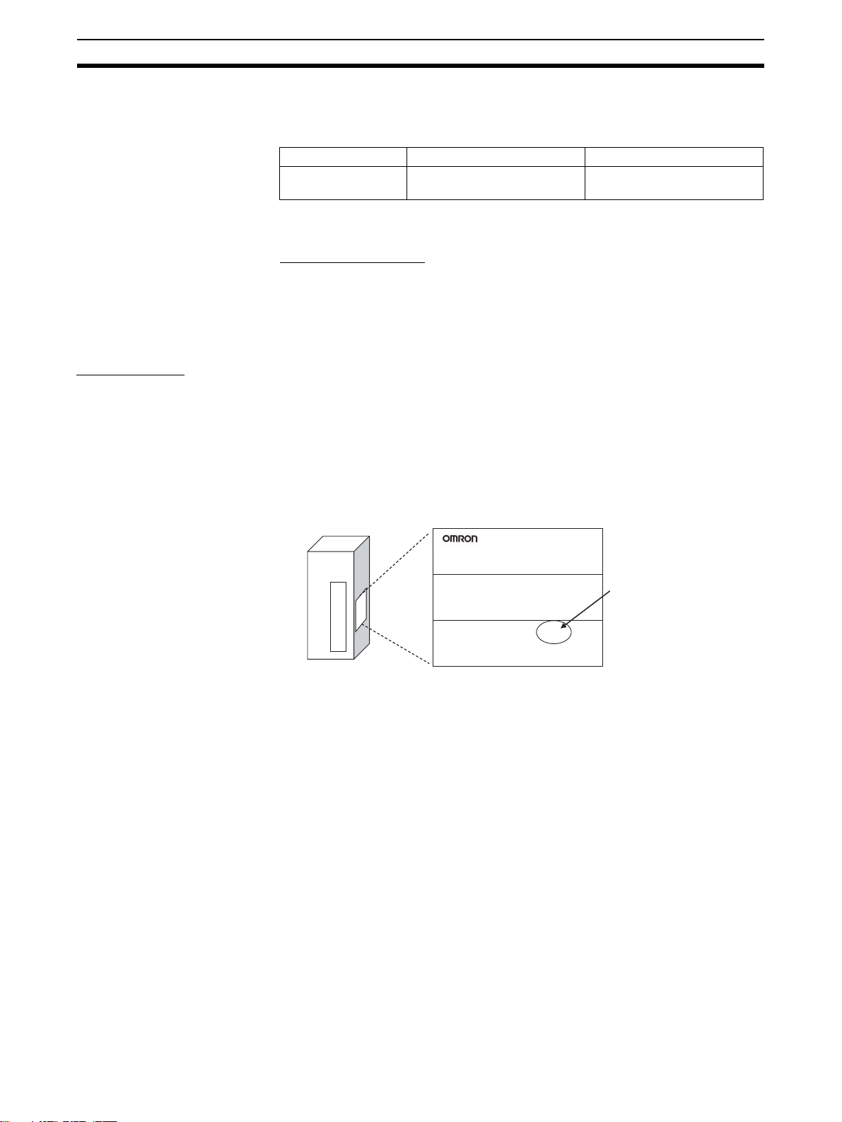
1. Unit Version Notation on Products
The unit version code is provided on the nameplate of the CS-series FL-net
Units for which unit versions are being managed, as shown below. This system applies to FL-net Units with unit version 1.0 or later.
Example: CS1W-FLN22 CS-series
FL-net Unit
Nameplate
CS1W-FLN22
FL-net UNIT
Unit version 1.0
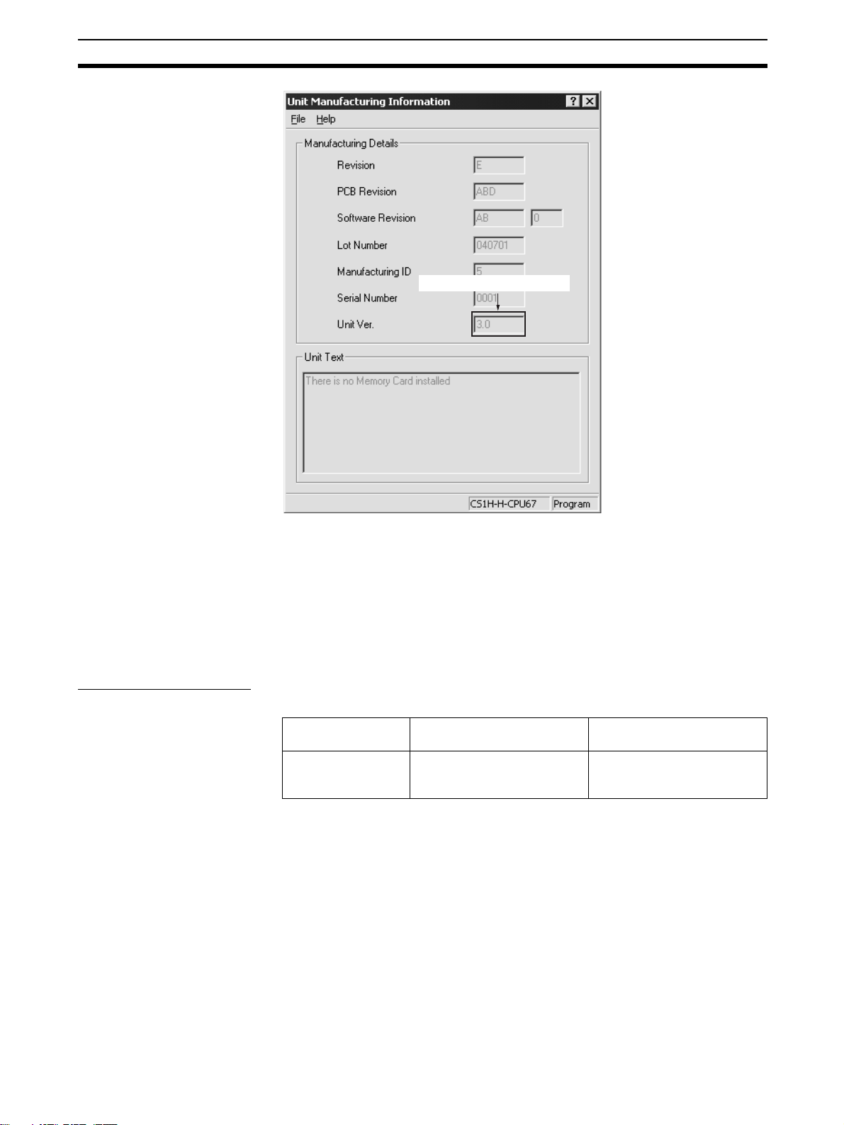
2. Confirming Unit Versions with Support Software
CX-Programmer version 5.0 can be used to confirm the unit version in the
Unit Manufacturing Information.
1. In the I/O Table Window, right-click on the FL-net Unit, and then select Unit
Manufacturing Information.
2. The following Unit Manufacturing Information Dialog Box will be displayed.
Lot No. 040301 0000 Ver.1.0
OMRON Corporation
MADE IN JAPAN
xxiv
Page 25
Unit Versions of CS/CJ-series FL-net Units 7
The unit version is displayed.
Example: In this Unit Manufacturing Information Dialog Box, unit version 1.0 is
displayed. Use this dialog box to confirm the unit version of the FL-net Unit
that is connected online.
3. Using the Unit Version Labels
Unit version labels are provided with the FL-net Unit. These labels can be
attached to the front of FL-net Units to differentiate from previous FL-net
Units.
Unit Version Notation
The unit versions are indicated in this manual as follows:
Notation in product
Ver.1.0 or later after
the lot number
nameplate
Notation in this manual Remarks
CS/CJ-series FL-net Units
with unit version 1.0 or later
Information for which no particular version is specified
applies to all unit versions.
xxv
Page 26

Unit Versions of CS/CJ-series FL-net Units 7
xxvi
Page 27

SECTION 1
Features and System Configuration
This section introduces the overall structure of an FL-net (Ver. 2.00) network, outlines the features of the FL-net (Ver. 2.00)
Unit, describes the communications protocols used by an FL-net (Ver. 2.00) network, and provides basic precautions for
use of the network.
1-1 FL-net Overview . . . . . . . . . . . . . . . . . . . . . . . . . . . . . . . . . . . . . . . . . . . . . . . 2
1-2 System Configuration . . . . . . . . . . . . . . . . . . . . . . . . . . . . . . . . . . . . . . . . . . . 7
1-2-1 Device Configuration . . . . . . . . . . . . . . . . . . . . . . . . . . . . . . . . . . . . 7
1-3 Related Programming Devices . . . . . . . . . . . . . . . . . . . . . . . . . . . . . . . . . . . . 8
1-4 Introducing the CX-FLnet Support Software . . . . . . . . . . . . . . . . . . . . . . . . . 8
1-5 Specifications . . . . . . . . . . . . . . . . . . . . . . . . . . . . . . . . . . . . . . . . . . . . . . . . . 9
1-6 Precautions . . . . . . . . . . . . . . . . . . . . . . . . . . . . . . . . . . . . . . . . . . . . . . . . . . . 13
1-6-1 Installation . . . . . . . . . . . . . . . . . . . . . . . . . . . . . . . . . . . . . . . . . . . . 13
1-6-2 Ethernet and IEEE802.3 Standards. . . . . . . . . . . . . . . . . . . . . . . . . . 13
1
Page 28
FL-net Overview Section 1-1
1-1 FL-net Overview
FL-net is an open FA network that was standardized by the Japan FA Open
Systems Promotion Group (JOP) of the Manufacturing Science and Technology Center (MSTC) under the Ministry of International Trade and Industry
(MITI). It has been established in the Japan Electrical Manufacturers standards (JEM 1479) and is becoming very popular.
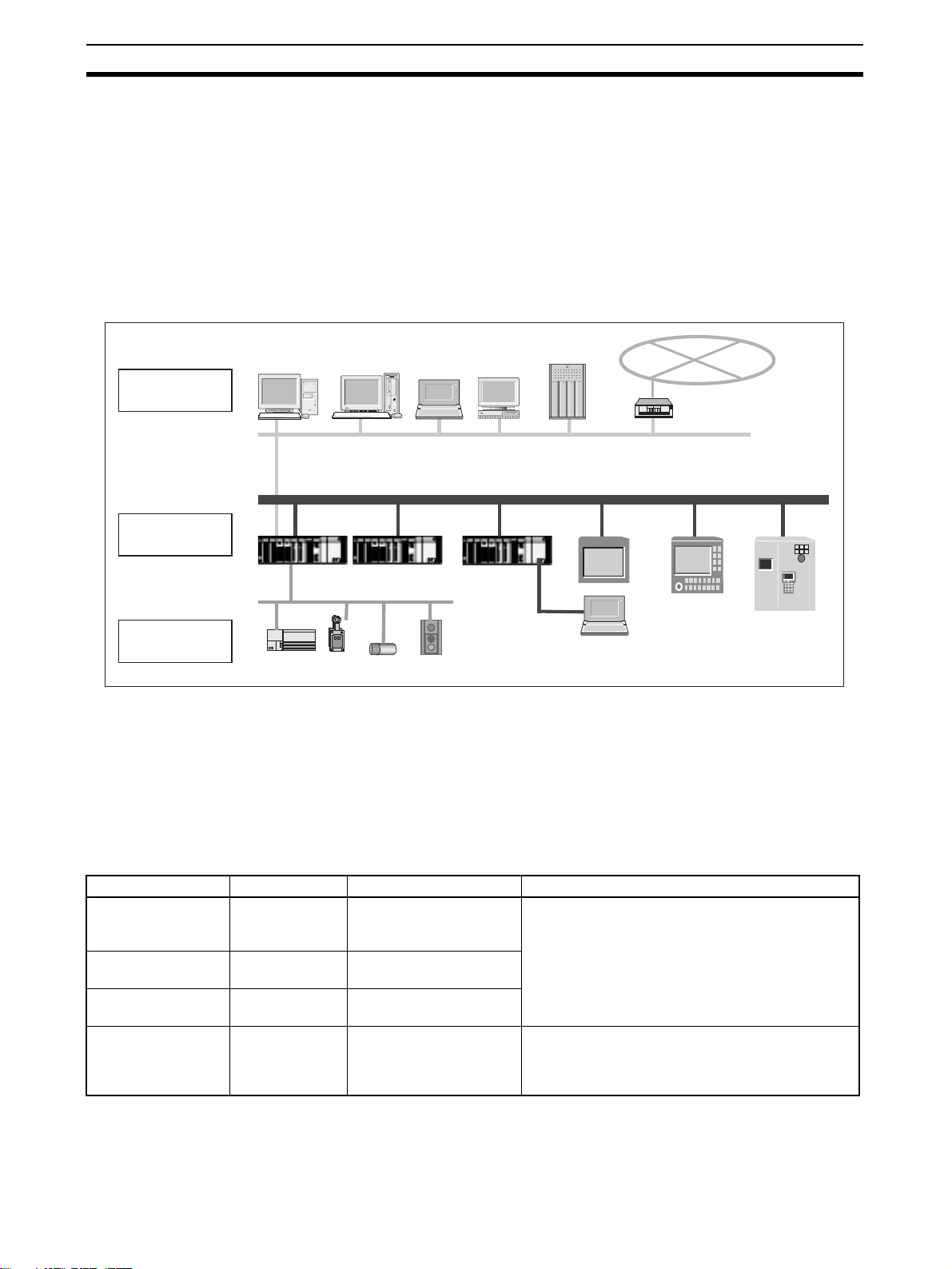
FL-net enables personal computers and FA controllers, such as programmable controllers (PLCs) or computerized numeric controllers (CNCs), by different manufacturers to be interconnected, controlled, and monitored, as shown
in the following diagram.
Personal
computer
EWS
Server
Computers
WAN
Host LAN Ethernet (TCP/IP, UDP)
FL-net Ethernet-based Control Network
Personal
computer
CNC
RC
Controllers
Devices
PLC
Field Network
PLC
PLC
Sensors
Actuators
FL-net Positioning FL-net Unit specifications have been designed to conform to Japan Electrical
Manufacturers standards (JEM 1479: 2001). It cannot be connected to communications devices based on the previous standards (JEM 1479: 2000).
The most recent FL-net specifications can be downloaded from the home
page of the Japan Electrical Manufacturers Association (http://www.jemanet.or.jp/English/).
The following table shows the relationship between these standards and the
FL-net Units manufactured and sold by OMRON.
Unit name Model Applicable standards Manufacture and sales
FL-net Unit,
100Base-TX
FL-net (Ver. 2.00)
Unit, 10Base-5
FL-net (Ver. 2.00)
Unit, 10Base-T
FL-net Unit CS1W-FLN01
CJ1W-FLN22
CJ1W-FLN22
(See note 2.)
CS1W-FLN02
(See note 2.)
CS1W-FLN12
(See note 2.)
(See note 1.)
Note 1. The
JEM1479: 2002 With FL-net Ver. 2.0 specifications (OPCN-2).
JEM 1479: 2001
JEM 1479: 2001
JEM 1479: 2000 Under the guidance of the JEMA, communications
devices conforming to JEM 1479: 2000 specifications cannot be manufactured or sold after April,
2001.
CS1W-FLN01 FL-net Unit cannot be connected to a network based on CS1W-
FLN02, CS1W-FLN12, CS1W-FLN22, or CJ1W-FLN22 FL-net Units.
2. CS1W-FLN02, CS1W-FLN12, CS1W-FLN22, or CJ1W-FLN22 FL-net Units cannot
be connected to a network based on the
CS1W-FLN01 FL-net Unit.
2
Page 29
FL-net Overview Section 1-1
FL-net Features FL-net System Concept
FL-net was designed to provide realtime communications between controllers
in manufacturing systems, such as programmable controllers (PLCs), robot
controllers (RCs), and computerized numeric controllers (CNCs). FL-net is
configured to broadcast tokens using the Ethernet UDP/IP protocols to enable
cyclic and message communications.
FL-net systems have the following features.
1. FL-net is an open system.
2. FL-net enables a multi-vendor network.
3. FL-net enables personal computers and FA controllers, such as programmable controllers (PLCs) or computerized numeric controllers (CNCs), by
different manufacturers to be interconnected, controlled, and monitored.
FL-net
Application layer User application Interface
FA link protocol layer Cyclic transmission Message service
Message
transmission
Token management
protocol
Transport layer UDP
Network layer IP
Data link layer Ethernet
Physical layer
Figure 1 Basic Configuration of FL-net Protocol
(IEEE802.3 standard)
Conforms to Widely Used Standards
Efficient communications can be achieved by this system based on Ethernet,
which has become the standard particularly for OA devices, combined with
standard UDP/IP. The use of Ethernet offers the following benefits.
1. Low cost
Configurations allowing the application of widely used communications de-
vices reduces costs.
2. Compatible with existing network devices
Transceivers, hubs, cables, LAN cards for personal computers, and other
network devices widely used for Ethernet can be used.
3. Higher speeds
Baud rates are expected to improve in the future, increasing to100 Mbps,
and 1 Gbps.
4. Optical communications
By using devices such as optical repeaters, which are widely used with
Ethernet, optic fiber can be used for necessary components to enable
long-distance transmission of over 500 m, improved noise resistance, and
measures against lightning surge on outdoor wiring.
3
Page 30

FL-net Overview Section 1-1
Supports Required Functions between FA Controllers
User-defined specifications allow the following range of features that are
required for FA systems.
1. Large-scale network
Up to 254 devices (nodes) can be connected in the physical layer of the
network.
2. Dual communications functions to suit application
The Common Memory function uses cyclic transmission so that each node
can always share the same data with other nodes on the network. FL-net
also supports message communications for use when handling only essential data is required.
3. Large-capacity Common Memory
The Common Memory is provided with a large capacity of 8 Kbits and 8
Kwords.
4. High-speed response
High-speed response time of 50 ms/32 nodes (for 2 Kbits and 2 Kwords)
is provided.
The absence of a master in the FL-net network enables nodes to be added
or removed readily without affecting any other nodes. This allows any node
to be turned ON or OFF easily and facilitates maintenance.
General Differences between Ethernet and FL-net
1. FL-net is a network designed for FA environments and is not compatible
with all general-purpose Ethernet devices. Some devices are not suitable
due to noise resistance and environment resistance requirements.
2. Only FL-net-compatible controllers and control devices can be connected
to FL-net to meet the demands of control applications requiring responsiveness in realtime communications.
3. FL-net is a cyclic communications method using the broadcasting supported by UDP/IP protocols based on the 10Base-5 and 10Base-T standards.
The following restrictions currently apply.
• Compatible devices mainly use 10 Mbps Ethernet LAN.
• Connection to other general-purpose Ethernet systems is not supported.
• TCP/IP are not supported.
• Switching hubs cannot be used effectively.
• Routers and similar devices may not be compatible.
FL-net FAQ
Question Answer
1 What is Ethernet? Ethernet is a standard defining a type of cable. It is used in a local area network (LAN). An
Ethernet network transmits data between computers at a baud rate of between 10 Mbps and
100 Mbps. Currently, the most commonly used Ethernet in offices and other OA systems is
twisted-pair cable (UTP) that uses 10 Mbps. Ethernet communications are possible using
software protocols provided by many vendors.
2 What is FL-net? The FL-net is a network to which programmable controllers (PLCs), computerized numeric
controllers (CNCs), and other FA controllers are connected, and on which control data is
exchanged between controllers at high speed. FL-net uses the same cables that are used for
Ethernet.
4
Page 31

FL-net Overview Section 1-1
Question Answer
3 What is the differ-
ence between FLnet and Ethernet?
4 How are FL-net
Units used?
5 What does “proto-
col” mean and what
protocols does FLnet support?
6 Can FL-net be con-
nected to a standard personal
computer?
7 What does “topol-
ogy” mean?
8 What type and
length of network
cables are used,
and how many Units
can be connected?
9 Do systems using
FL-net require special Ethernet specifications?
10 How do you connect
to FL-net?
11 What type of cables
should be used
when configuring an
FL-net system?
12 How is the FL-net IP
address set?
13 How compatible and
inter-connectable
are devices that
support FL-net?
With Ethernet, the host computer, personal computers, and controllers are connected to the
network for data exchange and control applications, such as executing production instructions
and compiling results. The FL-net is used to connect controllers together and allow highspeed control data exchange.
Be sure to connect cables properly when installing both Ethernet for communications with the
host and FL-net for communications between controllers for the same controllers.
FL-net Units are installed in FA controllers, such as programmable controllers (PLCs) and
computerized numeric controllers (CNCs). By simply setting link allocations for the local node
address (node number) and Common Memory (also called link registers), FL-net Units transmit data between controllers cyclically in the same way as CPU Link Units in standard PLCs.
This method does not require special communications programs for the PLC and other Units
on the network. Such programs are also not required by the PLC for operations conducted via
the personal computer, including reading or writing data, such as the PLC memory or communications parameters. Separate programs are required for each controller, however, when
transmitting data between controllers using message communications.
Protocol refers to rules for communications. The protocols supported by FL-net are UDP/IP
and FA Link Protocol. (The FA Link Protocol is located in the layer above UDP/IP and is a special protocol for use on FL-net networks.)
The FL-net Unit, which is mounted to FA controllers such as programmable controllers (PLCs)
and computerized numeric controllers (CNCs), is an intelligent unit with a processor on its
board. The Ethernet Card in the personal computer is a non-intelligent format called a “dumb
board,” so its capacity depends on the performance and functions of the personal computer.
Generally, an intelligent FL-net board is recommended.
Networking topology refers to the wiring formation of the network. The three main formations
are star (or tree), bus, and ring. Rather than physical wiring formations, however, it is easier to
understand them as theoretical formations. An FL-net system has star topology when using
10Base-T cables and bus topology when using 10Base-5 cables.
The most commonly used Ethernet cable standards and some of their characteristics and limitations are listed below. The figures in parentheses are applicable when repeaters are used.
• 10Base-T: Twisted-pair cables (UTP), maximum transmission distance is 100 m (500 m)
per segment, maximum number of Units is 254 per segment.
• 10Base-5: Thick coaxial cables (yellow cables), maximum transmission distance is 500 m
(2,500 m) per segment, and maximum number of Units that can be connected is 100
(254) per segment.
• 10Base-FL: Optic fiber cable, maximum transmission distance is 2,000 m per segment,
and maximum number of Units that can be connected is 254 per segment.
No. FL-net systems are configured using Ethernet (conforming to the IEEE802.3 standard).
Special specifications are not required.
Ethernet cables for different types of Ethernet media can be connected to each other using
repeaters, media adapters, and other devices. These products are available from many vendors.
In general, use the following cables.
• Basic wiring: 10Base-5 Thick coaxial cables; yellow cables.
• In the control panel and in offices: 10Base-T twisted-pair cables; UTP category 5.
• High-voltage wiring and noise-prone environments: 10Base-FL optic-fiber cables.
The FL-net IP address is set as follows:
Network address: 192.168.250
Host number (node number): 1 to 254 is standard. Nodes 250 to 254, however, are reserved
for maintenance devices.
FL-net has a certification system whereby compatibility and inter-connectivity tests are per-
formed.
Certification documents are provided for those devices that pass the tests, so devices sup-
porting FL-net can be used safely on the network.
5
Page 32

FL-net Overview Section 1-1
OMRON FL-net Unit (100Base-TX) Features
High-speed
Communications at
100 Mbps
Specify the Order of Data
Link Data
FINS Message
Communications
Controller Link Network
Connection
Abundant
Troubleshooting
Functions
A baud rate of 100 Mbps is supported. The baud rate can be automatically
selected or a fixed baud rate of 10 Mbps can be set.
The order of upper/lower bytes in data link data (word data) can be specified
for each node before sending or receiving the data, according to the specifications of the device connected in the data link.
The FL-net Unit also supports FINS message communications, OMRON’s
standard communications service, so other OMRON PLCs can be accessed
by using SEND(090), RECV(098), and CMND(490) instructions in ladder programs. In addition, the FINS gateway function can be used to allow access to
other PLCs on not only the same FL-net network but also on other networks
such as Ethernet or Controller Link.
Ethernet, the information-system network, can be connected to Controller
Link, the control-system network, using the FINS communications service.
This allows a PLC on the Ethernet or Controller Link network to be monitored
from an OMRON PLC on the FL-net network, and, conversely, for data to be
exchanged between a PLC on the Ethernet or Controller Link network and an
OMRON PLC on the FL-net network.
The Ethernet Unit is provided with a variety of troubleshooting functions for
prompt recovery in case of errors.
• Self-diagnostic function at startup
• PING command for checking other nodes
• Inter-nodal tests for checking other nodes
• Error log for recording error history data
6
Page 33

System Configuration Section 1-2
1-2 System Configuration
1-2-1 Device Configuration
10Base-T
FL-net (Ver. 2.00) (10 Mbps)
Terminator
Between nodes:
Integral multiples of 2.5 m
500 m/segment max.
10Base-5 coaxial cable
(or 10Base-T twisted-pair cable)
Terminator
Transceiver
Transceiver cable
CS/CJ-series
CS1W-FLN22 or
CJ1W-FLN22
FL-net Unit
100Base-TX
Twisted-pair
cable
50 m max.
Other company's
FL-net (Ver. 2.0) node
10Base-T
CS-series
PLC
CS-series
DeviceNet Unit
Hub
Hub Hub
Hub
100 m max.
CS-series
CS1W-FLN12
FL-net (Ver. 2.00) Unit
(10Base-T)
DeviceNet
SensorRemote Terminal Actuator
Ground
Other company's
FL-net (Ver. 2.0) node
10Base-T
CX-Programmer
CS-series
CS1W-FLN22
FL-net Unit
(100Base-TX)
100 m max. 100 m max. 100 m max.
CS-series PLC
CS-series
CJ1W-FLN22
FL-net Unit
(100Base-TX)
CS-series DeviceNet Unit
Remote Terminal Sensor Actuator
CS-series
CS1W-FLN22
FL-net Unit
(100Base-TX)
Note Do not combine nodes using a baud rate of 10 Mbps with nodes using a baud
rate of 100 Mbps in the same configuration, where possible. If nodes with a
baud rate of 10 Mbps are used, use a baud rate of 10 Mbps for all the connected devices in the configuration.
Other company's
FL-net node
100Base-TX
DeviceNet
7
Page 34

Related Programming Devices Section 1-3
1-3 Related Programming Devices
The FL-net Unit functions as a node on the FL-net network. The basic settings
for operation are made in the CPU Bus Unit System Setup in the CS/CJseries CPU Unit. Use the CX-FLnet or FL-net Unit Support Software to make
the settings.
Personal computer running Windows
CX-FLnet or FL-net Unit Support Software
CPU Bus Unit
System Setup
FL-net Unit
CS/CJ-series CPU Unit
The following items are included in the Setup Area.
Screen Item Default Page
Setup Screen FA Link mapping table method PLC built-in method 50
FA Link startup method Automatic participation 50
Message protocol confirmation Yes 50
Broadcast type ***.***.***.255 50
IP address setting method 192.168.250.node number 50
Subnet mask 255.255.255.0 50
Baud rate 10 Mbps 50
Local node setup area Not set. 50
Other node setup area Not set. 50
Data order setting No swapping (sequential order) 79
Screen
When using the default values that are already stored in the CS/CJ-series
CPU Unit, there is no need to make any settings with the CX-FLnet or FL-net
Unit Support Software. Refer to 4-2 CPU Bus Unit System Setup for details on
the above settings.
1-4 Introducing the CX-FLnet Support Software
The FL-net Unit Support Software can be installed from the CX-One FA Integrated Tool Package (version 1.1 or higher) as the CX-FLnet. The following
table compares the FL-net and CX-FLnet. Other aspects are the same.
Item Previous Support Software:
Obtaining the software Downloaded from the OMRON Industrial
Website.
Simultaneously being online with
other Programming Device software that uses the CX-Server,
such as the CX-Programmer
Starting the software From the Windows Start Menu From the Windows Start Menu or from the
Not possible. Possible.
FL-net version 1.6
Provided with CX-One version 1.1 or
higher (CXONE-AL@@C-E)
I/O Table Window of the CX-Programmer
installed from CX-One. (Right-click the
FL-net Unit and use the pop-up menu.)
8
New Support Software:
CX-FLnet
Page 35

Specifications Section 1-5
1-5 Specifications
CS-series FL-net Units
Item Specifications
Model number CS1W-FLN22
Type 100Base-TX (10Base-T is also possible)
Applicable PLCs CS-series PLCs
Unit classification CS-series CPU Bus Unit
Mounting location CPU Rack or Expansion Rack
Number of Units that can be
mounted
Transfer
specifications
Current consumption (Unit) 380 mA max. at 5 VDC
Vibration resistance Conforms to JIS 0040.
Shock resistance Conforms to JIS 0041.
Ambient temperature Operating: 0 to 55°C
Humidity 10% to 90% (with no condensation)
Atmosphere Must be free from corrosive gas.
Weight 200 g max.
Dimensions 35 × 130 ×101 mm (W × H × D)
Media access method CSMA/CD
Modulation Baseband
Transmission paths Star
Baud rate 100 Mbps (100Base-TX) 10 Mbps (10Base-T)
Transmission media Unshielded twisted-pair (UTP) cable
Transmission distance 100 m max. (distance between hub and node)
Number of cascade
connections with
repeater hub
4 max. (including Expansion Racks)
Unshielded twisted-pair (UTP) cable
Categories: 5, 5e
Shielded twisted-pair (STP) cable
Categories: 100 Ω at 5, 5e
24
10 to 57 Hz, 0.075-mm amplitude, 57 to 150 Hz, acceleration: 9.8 m/s
directions for 80 minutes each
(Time coefficient; 8 minutes × coefficient factor 10 = total time 80 minutes)
147 m/s
Storage: –20 to 75°C
2
three times each in X, Y, and Z directions
Categories: 3, 4, 5, 5e
Shielded twisted-pair (STP) cable
Categories: 100 Ω at 3, 4, 5, 5e
2
in X, Y, and Z
9
Page 36

Specifications Section 1-5
CJ-series FL-net Units
Item Specifications
Model number CJ1W-FLN22
Type 100Base-TX (10Base-T is also possible)
Applicable PLCs CJ-series PLCs
Unit classification CJ-series CPU Bus Unit
Mounting location CPU Rack or Expansion Rack
Number of Units that can be
mounted
Transfer
specifications
Current consumption (Unit) 370 mA max. at 5 VDC
Vibration resistance Conforms to JIS 0040.
Shock resistance Conforms to JIS 0041.
Ambient temperature Operating: 0 to 55°C
Humidity 10% to 90% (with no condensation)
Atmosphere Must be free from corrosive gas.
Weight 100 g max.
Dimensions 31 × 90 × 65 mm (W × H × D)
Media access method CSMA/CD
Modulation Baseband
Transmission paths Star
Baud rate 100 Mbps (100Base-TX) 10 Mbps (10Base-T)
Transmission media Unshielded twisted-pair (UTP) cable
Transmission distance 100 m max. (distance between hub and node)
Number of cascade
connections with
repeater hub
4 max. (including Expansion Racks)
Unshielded twisted-pair (UTP) cable
Categories: 5, 5e
Shielded twisted-pair (STP) cable
Categories: 100 Ω at 5, 5e
24
10 to 57 Hz, 0.075-mm amplitude, 57 to 150 Hz, acceleration: 9.8 m/s
directions for 80 minutes each
(Time coefficient; 8 minutes × coefficient factor 10 = total time 80 minutes)
147 m/s
Storage: –20 to 75°C
2
three times each in X, Y, and Z directions
Categories: 3, 4, 5, 5e
Shielded twisted-pair (STP) cable
Categories: 100 Ω at 3, 4, 5, 5e
2
in X, Y, and Z
10
Page 37

Specifications Section 1-5
Dimensions
CS1W-FLN22
FLN22
RUN
HER
TX
RX
NODE
0
NO.
130
100BASE-TX
10BASE-T
CJ1W-FLN22
UNIT
NO.
16
100M
PER
LNK
MSG
TS
0
1
0
1
16
10135
(Unit: mm)
31
65
90 2.72.7
FLN22
RUN HER TX RX
PER LNK MSG TS100M
100BASE-TX
10BASE-T
5
4
UNIT
6
3
7
2
8
1
9
0
A
F
No.
B
E
C
D
5
4
NODE
6
3
7
2
8
1
9
0
A
F
No.
B
E
C
D
1
x16
5
4
6
3
7
2
8
1
9
0
A
F
B
E
C
D
0
x16
(Unit: mm)
11
Page 38

Specifications Section 1-5
Comparison with Previous Models (CS1W-FLN02, CS1W-FLN12)
Model CS1W-FLN22
Type 100Base-TX (10Base-T is also possible) 10Base-5 (CS1W-FLN02)
Switches/indicators
Data link functions
100M indicator provided
This indicator indicates when baud rate of 100
Mbps is being used.
No rotary switch for setting the IP address.
The IP address is set using the CX-FLnet or FLnet Unit Support Software. Either of the following
two methods can be used to set the IP address.
1. 192.168.250 + node number
2. Setup area
Total capacity: 8,704 words
(Area 1: 512 words, Area 2: 8,192 words)
If the total number of words in Area 1 and Area 2
for a single node exceeds 7,677 words, the data
for the corresponding node will be refreshed over
two scans of the CPU Unit. The data will be split
from the 7,678th word counted from the beginning
of the combined Area 1 and Area 2.
The order of the upper and lower byte in the word
data can be swapped for each node when
exchanging data between the data link area in the
PLC and the FL-net.
CJ1W-FLN22
10Base-T (CS1W-FLN12)
No 100M indicator
Rotary switch provided on rear of Unit for setting
the IP address. Either of the following four methods can be used to set the IP address
1. 192.168.250 + node number
2. Rotary switch on rear of Unit.
3. Rotary switch on rear of Unit + node number
4. Setup area
Total capacity: 8,704 words
(Area 1: 512 words, Area 2: 8,192 words)
Data link tables that exceed the following conditions, however, cannot be set.
Number of words in local node setup area (Area 1
and Area 2) ≤ 7,677 words.
Number of words in local node setup area (Area 1
and Area 2) + the number of words in setup area
(Area 1 and Area 2) for node with the largest setup
area size (except local node) ≤ 7,677 words
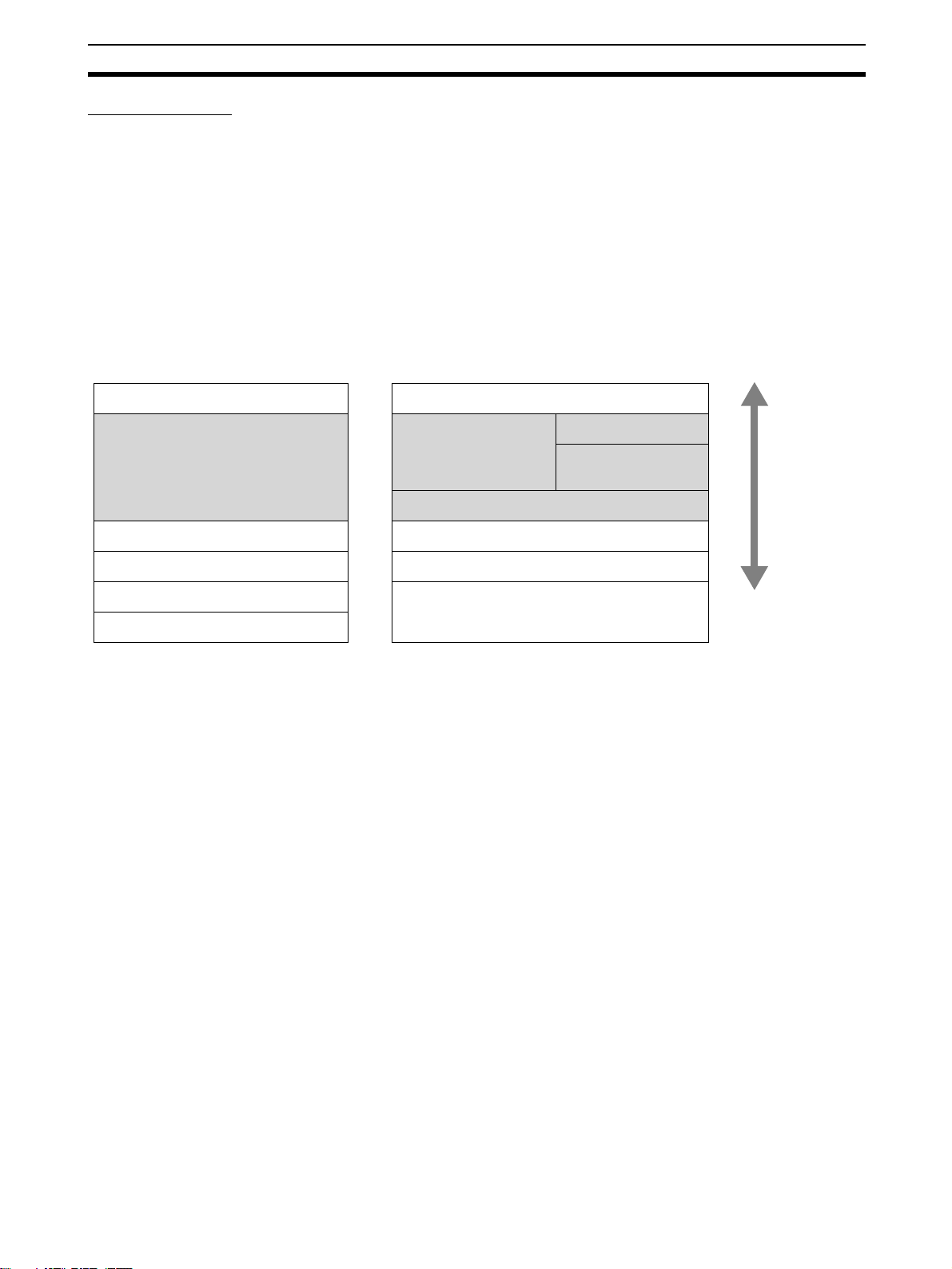
The data order cannot be changed and is fixed as
shown in the following diagram.
Common memory
MSB LSB
CS1W-FLN02/12
Simple backup
function
Support Software
Supported. Not supported.
CX-FLnet or FL-net Unit Support Software version
1.60 or higher (CS1W-FLN22 and CJ1W-FLN22
settings cannot be made using Ver. 1.51 or lower)
Comparison between FL-net Unit Support Software
Version CX-FLnet or
FL-net Unit Support Software Ver. 1.60
New setting
function
Connection with
PLC
Setting file Setting files saved from Japanese version and
Set the baud rate.
Set the data link data order.
Set/monitor other nodes via the FL-net network. Only the local node can be set or monitored.
English version are compatible.
PLC memory area
D15 0
FL-net Unit Support Software Ver. 1.51 or higher
(CS1W-FLN02 and CS1W-FLN12 settings can
also be made using Ver. 1.60 or higher)
Ver. 1.51
None (these settings are not available)
No compatibility between setting files saved in the
English version and Japanese version.
12
Page 39

Precautions Section 1-6
1-6 Precautions
Be sure to observe the following precautions when installing and using an FLnet Unit.
1-6-1 Installation
Observe the following precautions when installing an FL-net Unit.
1,2,3... 1. Use transceiver cable that meets IEEE802.3 standards to ensure high
noise resistance.
2. Use a transceiver with a current consumption of not more than 0.4 A per
port.
3. Always turn OFF the power supply to the PLC before connecting or disconnecting the transceiver cable.
4. Be sure not to exceed the current capacity of the Power Supply Unit on the
Rack to which the FL-net Unit is mounted. The current consumption is 380
mA maximum for the CS-series FL-net Unit and 370 mA for the CJ-series
FL-net Unit. This value added to the current consumption of all other Units
mounted to the same Rack must not exceed the capacity of the Power
Supply Unit.
5. Do not install the transceiver cables or coaxial cables of the network near
power supply lines. If installation near possible sources of noise is unavoidable, install the cables in grounded metal ducts or take other measure to
eliminate noise interference.
1-6-2 Ethernet and IEEE802.3 Standards
The FL-net Unit was designed based on Version-2.0 Ethernet standards and
not on the international IEEE802.3 standards, which were developed based
on Ethernet specifications. Although these two sets of standards are similar,
they are not necessarily the same. Particularly, different frame formats are
used, making direct communications impossible between systems that do not
support the same standards. Standards for equipment used to configure networks are the same, allowing IEEE802.3-standard equipment to be used with
the FL-net Unit. In particular, the transceiver cable for the IEEE802.3 standards provides superior noise resistance and should be used for the FL-net
Unit.
Terminology also differs between Version-2.0 Ethernet and IEEE802.3 standards. These differences are shown in the following table. Version-2.0 Ether-
net terminology is used in this manual.
Ethernet IEEE802.3
Transceiver MAU
Transceiver cable AUI
Ethernet address MAC address
Ethernet 10Base-5/10Base-T
13
Page 40

Precautions Section 1-6
14
Page 41

SECTION 2
Communications Functions
This section describes the communications functions that can be used with the FL-net (Ver. 2.00) Units.
2-1 FL-net . . . . . . . . . . . . . . . . . . . . . . . . . . . . . . . . . . . . . . . . . . . . . . . . . . . . . . . 16
2-2 Cyclic Transmission . . . . . . . . . . . . . . . . . . . . . . . . . . . . . . . . . . . . . . . . . . . . 20
2-3 Message Transmission . . . . . . . . . . . . . . . . . . . . . . . . . . . . . . . . . . . . . . . . . . 21
2-4 FINS Communications Service. . . . . . . . . . . . . . . . . . . . . . . . . . . . . . . . . . . . 22
15
Page 42

FL-net Section 2-1
2-1 FL-net
FL-net Concept FL-net is an Ethernet-based FA control network.
FL-net supports both cyclic transmission and message transmission functions.
The basic concepts of FL-net are as follows:
1,2,3... 1. To use Ethernet as the medium for communications between FA control-
lers.
2. To offer UDP/IP, which are widely used protocols in Ethernet communications, as the basic means for data communications.
3. To manage and control access of each node in the network to the communications media (to avoid collisions) and to ensure transmission within a
fixed time period, while using the above-mentioned basic means for data
communications.
FL-net is an FA control network enabling the exchange of data between control devices in manufacturing systems, such as programmable controllers
(PLCs), robot controllers (RCs), and computerized numeric controllers
(CNCs), and personal computers used for controlling them.
The following diagram shows the location of devices in an FL-net system.
Computers
Controllers
Devices
Personal
computer
Personal
computer
PLC
DeviceNet or other network
Personal
computer
Host LAN Ethernet (TCP/IP, UDP)
FL-net Ethernet-based Control Network
PLC
EWS
Sensors
Actuators
PLC
Server
Personal
computer
OMRON CX-FLnet or
FL-net Unit Support Software
WAN
CNC
RC
16
Page 43

FL-net Section 2-1
FL-net Protocol FL-net consists of six protocol layers, as shown in the following diagram.
Application layer User application Interface
Message service
Cyclic transmission
FA link protocol layer
Token management
Transport layer UDP
Network layer IP
Data link layer Ethernet
(IEEE802.3 standard)
Note The transport and network layers use UDP/IP, whereas Ethernet is used as
the protocol for the data link and physical layers.
Message transmis-
sion
FL-net
Protocol
FL-net Transmission
FL-net's FA link protocol layer is characterized by the following features.
Features
1,2,3... 1. Collisions are avoided by transmission control that uses the token method
that does not use a master.
2. The refresh cycle time can be regulated by fixing the cycle time of the token.
3. The designated token is transmitted together with cyclic data.
4. The token is transmitted first by the node that has the smallest number at
startup.
5. When no token is transmitted in a specified period of time, the next node
in the token rotation order sends a new token.
6. This token method prevents the network from stopping when there is a failure of only some of the nodes.
7. The information management tables provide useful information, such as
operation mode (RUN/STOP) and hardware malfunctions (ALARM), that
can be referenced to monitor the operating status of other nodes.
FL-net IP Addresses Unique class-C IP addresses must be assigned to each node in the FL-net
network.
An IP address is an address identifying each node (station) for transmission
using IP (internet protocol). Therefore, IP addresses must be set and managed so that no two nodes have the same IP address. FL-net uses Class-C IP
addresses. The default IP address for FL-net is 192.168.250.***, with *** representing the remote node number.
FL-net (Ver.
2.00) IP
address
Network address Host number
(node number)
192.168.250 n (n: 1 to 254)
17
Page 44

FL-net Section 2-1
Number of Connectable
Nodes and Node Numbers
Note 1. Not available to users.
Network address
Node number
Up to 254 nodes can be connected to an FL-net network. Each node is
assigned a node number from 1 to 254.
Node number Applications
1 to 249 Used for standard FL-net devices.
250 to 254 Used for FL-net maintenance purposes.
255 Reserved for the internal system use. (See notes 1 and 2.)
0 Reserved for internal system use. (See note 1.)
2. Used for broadcasting.
FL-net
192.
168.
250.
1
192.
168.
250.
2
192.
168.
250.
248
192.
168.
250.
249
192.
168.
250.
250
192.
168.
250.
254
Node number: 1 to 249 (for users)
Node number: 250 to 254
(for maintenance)
Data Communications FL-net supports data communications by cyclic transmission and message
transmission.
Message data
Cyclic transmission
Cyclic data with token
Cyclic transmission + message transmission
Transmission Cycle With cyclic communications, the Common Memory is refreshed on a fixed
cycle time. Message communications are controlled so that the Common
Memory refresh time does not exceed the allowable refresh cycle time.
Each node constantly monitors the message communications frames that
travel through the network from the time it receives one local-node-directed
token until it receives the next local-node-directed token. When no message
communications frame travels through the network in a single cycle, 120% of
the cycle time value becomes the allowable refresh cycle time. In this way the
allowable refresh cycle time is actively determined according to the number of
nodes in the network.
18
Page 45

FL-net Section 2-1
Data Areas and Memory
FL-net
FL-net Communications Unit
Cyclic transmission
Message transmission
Communications
Management Tables
Local Node Management
Table
Node number 1 byte 1 to 249
Common Memory Area 1 first word 2 bytes Word address (0 to 0xff)
Common Memory Area 1 data size 2 bytes Size (0 to 0x200)
Common Memory Area 2 first word 2 bytes Word address (0 to 0x1fff)
Common Memory Area 2 data size 2 bytes Size (0 to 0x2000)
Upper layer status 2 bytes RUN/STOP /ALARM/WARNING/NORMAL
Token monitoring time 1 byte Unit: 1 ms
Minimum allowable frame interval 1 byte Unit: 100 µs
Vendor code 10 bytes Vendor code
Manufacturer model 10 bytes Manufacturer model, device name
Node name (equipment name) 10 bytes User-defined node name
Protocol version 1 byte 0x80 (fixed)
FA link status 1 byte Participating, not participating, etc.
Local node status 1 byte Duplicate node number detection, etc.
CPU Unit
Common Memory Area 1
Common Memory Area 2
Message transmission buffer area
FL-net management table area
FL-net parameter area
Physical memory
Node status is managed using three types of management tables: Local node
management tables, participating node management tables, and network
management
The local node management table manages the local node settings.
Item Bytes Contents (data range)
Note “0x0012ab” refers to hexadecimal 0012AB.
19
Page 46

Cyclic Transmission Section 2-2
Participating Node
Management Table
Node number 1 byte 1 to 254
Upper layer status 2 bytes RUN/STOP /ALARM/WARNING/NOR-
Common Memory Area 1 data first word 2 bytes Word address (0 to 0x1ff)
Common Memory Area 1 data size 2 bytes Size (0 to 0x200)
Common Memory Area 2 data first word 2 bytes Word address (0 to 0x1fff)
Common Memory Area 2 data size 2 bytes Size (0 to 0x2000)
Minimum allowable refresh cycle time 2 bytes Unit: 1 ms
Token monitoring time 1 byte Unit: 1 ms
Minimum allowable frame interval 1 byte Unit: 100 ms
Link status 1 byte Participating, not participating, etc.
Network Management
Table
The participating node management table manages information on the nodes
in the network.
Item Bytes Contents (data range)
MAL
Note “0x0012ab” refers to hexadecimal 0012AB.
The network management table manages information that is shared by all
nodes on the network.
Item Bytes Contents (data range)
Token holding node number 1 byte Node currently holding the token
Minimum allowable frame interval 1 byte Unit: 100 µs
Allowable refresh cycle time 2 bytes Unit: 1 ms
Refresh cycle measurement value
(current)
Refresh cycle measurement value
(maximum)
Refresh cycle measurement value
(minimum)
2 bytes Unit: 1 ms
2 bytes Unit: 1 ms
2 bytes Unit: 1 ms
2-2 Cyclic Transmission
Cyclic transmission is used to transmit cyclic data. The data is shared by each
node through the Common Memory (shared memory) function.
To ke n D at a
Node 1 Node 2 Node 3 Node... Node n
Node 1
Node 2
Node 3
Node 4
Node...
Node n
Node 1
Node 2
Node 3
Node 4
Node...
Node n
Note Cyclic transmission allows PLCs made by OMRON to communicate with
PLCs made by other companies.
FL-net
Node 1
Node 2
Node 3
Node 4
Node...
Node n
Node 1
Node 2
Node 3
Node 4
Node...
Node n
Node 1
Node 2
Node 3
Node 4
Node...
Node n
Common
Memory
20
Page 47

Message Transmission Section 2-3
Volume of Transmission
Data
An area of 0.5 Kwords + 8 Kwords = 8.5 Kwords is provided for the whole network.
The maximum quantity of data that can be transmitted by a single node is
8.5 Kwords. One word is equal to two bytes.
15
2
Area 1
Area 2
2-3 Message Transmission
Message transmission is used to transmit non-cyclic data.
Normally, when a send request is generated, data is transmitted to a specific
node.
0
2
0.5 Kw
0.5 Kwords
8Kwords
Common Memory Area
Message transmission from node 1 to node 3
Message transmission from node 6 to node 4
FL-net
1 2
3 4 5 6
Note 1. Message transmission allows OMRON PLCs to communicate with other
manufacturer’s PLCs.
2. Message transmission is performed between OMRON PLCs by executing
the SEND(090), RECV(098), and CMND(490) instructions.
3. Message transmission is performed between OMRON PLCs and other
manufacturer’s PLCs by executing the CMND(490) instruction.
Message Transmissions The maximum size of one message frame is 1,024 bytes (not including the
header).
Message frame
1,024 bytes
21
Page 48

FINS Communications Service Section 2-4
2-4 FINS Communications Service
FINS commands or data can be sent to or received from other manufacturer’s
PLCs on the same FL-net network by executing SEND(090), RECV(098), or
CMND(490) instructions in the user’s ladder diagram program in the CPU
Unit. This enables control operations such as the reading and writing of I/O
memory between PLCs, mode changes, and file memory operations. (When a
FINS message is sent on an Ethernet network, a UDP/IP header is automatically added to the message.)
The FINS gateway function allows access not only to OMRON PLCs on the
same FL-net network, but also to PLCs on other networks such as SYSMAC
LINK or Controller Link.
User program
FinsGateway API
Ethernet
UDPIP FINS
CS-series
PLC
Ethernet Unit
FL-net Unit
FL-net
UDPIP FL-net FINS UDPIP FL-net FINS
FL-net Unit FL-net Unit
User program
SEND/RECV
instruction or
CMND instruction
The FINS communications service allows PLC Programming Devices like the
CX-Programmer to be used with a remote PLC.
CX-Programmer
Ethernet
UDPIP FINS
CS-series
PLC
Ethernet Unit
FL-net Unit FL-net Unit
FL-net
UDPIP FL- net FI NS
22
Note 1. The FINS communications service can send messages between OMRON
PLCs.
2. It cannot send messages to other manufacturer’s PLCs.
Page 49

FINS Communications Service Section 2-4
Message Data Length The FL-net Unit creates FINS communications messages through FL-net
message transmission. Maximum length for a FINS communications message is 1,024 bytes (including the FINS header and text).
FL-net message frame
1,024 bytes
FINS header
10 bytes
FINS header
10 bytes
Command
code
Command
code
2 bytes
Completion
code
2 bytes
Te xt
1,012 bytes2 bytes
Te xt
1,010 bytes
23
Page 50

Page 51

SECTION 3
Startup Procedure
This section explains the procedure for starting up the FL-net (Ver. 2.00) Unit, including mounting to the PLC, making the
required settings, and checking communications.
3-1 Before Operation. . . . . . . . . . . . . . . . . . . . . . . . . . . . . . . . . . . . . . . . . . . . . . . 26
3-2 Initial Setup . . . . . . . . . . . . . . . . . . . . . . . . . . . . . . . . . . . . . . . . . . . . . . . . . . . 27
3-3 Nomenclature and Functions . . . . . . . . . . . . . . . . . . . . . . . . . . . . . . . . . . . . . 28
3-4 Hardware Setup. . . . . . . . . . . . . . . . . . . . . . . . . . . . . . . . . . . . . . . . . . . . . . . . 30
3-5 Mounting to the PLC. . . . . . . . . . . . . . . . . . . . . . . . . . . . . . . . . . . . . . . . . . . . 33
3-6 Network Installation . . . . . . . . . . . . . . . . . . . . . . . . . . . . . . . . . . . . . . . . . . . . 34
3-6-1 Basic Installation Precautions. . . . . . . . . . . . . . . . . . . . . . . . . . . . . . 34
3-6-2 Recommended Products . . . . . . . . . . . . . . . . . . . . . . . . . . . . . . . . . . 35
3-6-3 Precautions . . . . . . . . . . . . . . . . . . . . . . . . . . . . . . . . . . . . . . . . . . . . 35
3-6-4 Noise Reduction when Using Contact Outputs . . . . . . . . . . . . . . . . 37
3-7 Connecting to the Network . . . . . . . . . . . . . . . . . . . . . . . . . . . . . . . . . . . . . . . 38
3-7-1 Ethernet Connectors . . . . . . . . . . . . . . . . . . . . . . . . . . . . . . . . . . . . . 38
3-7-2 Connecting the Cable . . . . . . . . . . . . . . . . . . . . . . . . . . . . . . . . . . . . 38
3-8 Creating an I/O Table . . . . . . . . . . . . . . . . . . . . . . . . . . . . . . . . . . . . . . . . . . . 39
3-8-1 I/O Table Overview. . . . . . . . . . . . . . . . . . . . . . . . . . . . . . . . . . . . . . 39
3-8-2 Connecting Programming Devices to the PLC. . . . . . . . . . . . . . . . . 39
3-8-3 Procedure for Creating an I/O Table. . . . . . . . . . . . . . . . . . . . . . . . . 40
3-9 Creating Routing Tables . . . . . . . . . . . . . . . . . . . . . . . . . . . . . . . . . . . . . . . . . 40
3-9-1 Routing Table Overview . . . . . . . . . . . . . . . . . . . . . . . . . . . . . . . . . . 41
3-9-2 Connecting and Using a Peripheral Device for the PLC . . . . . . . . . 42
3-10 System Setup. . . . . . . . . . . . . . . . . . . . . . . . . . . . . . . . . . . . . . . . . . . . . . . . . . 45
3-10-1 When Settings are Required . . . . . . . . . . . . . . . . . . . . . . . . . . . . . . . 45
3-10-2 Using the CX-FLnet or FL-net Unit Support Software . . . . . . . . . . 45
3-10-3 CPU Bus Unit System Setup Defaults . . . . . . . . . . . . . . . . . . . . . . . 45
3-11 Checking Communications . . . . . . . . . . . . . . . . . . . . . . . . . . . . . . . . . . . . . . . 46
3-11-1 PING Command and Internode Testing . . . . . . . . . . . . . . . . . . . . . . 46
3-11-2 PING Command . . . . . . . . . . . . . . . . . . . . . . . . . . . . . . . . . . . . . . . . 46
3-11-3 Internode Test . . . . . . . . . . . . . . . . . . . . . . . . . . . . . . . . . . . . . . . . . . 46
25
Page 52

Before Operation Section 3-1
3-1 Before Operation
Precautions Observe the following precautions when installing and using an FL-net Unit.
Installation Precautions Observe the following precautions when installing an FL-net Unit.
• Make sure that all of the nodes in the network are CS1W-FLN22, CJ1WFLN22, CS1W-FLN02, or CS1W-FLN12. CS1W-FLN01 FL-net Units cannot be connected.
FL-net network
version
V2.00 CS1W-FLN22
V.100 CS1W-FLN01
• Use a transceiver cable that complies with the IEEE802.3 standards to
ensure high noise resistance.
• Use a transceiver with a current consumption of not more than 0.4 A per
port.
• Always turn OFF the power supply to the PLC before connecting or disconnecting the transceiver cable.
• The current consumption of the FL-net Unit is 400 mA maximum. Make
sure that the total current consumption of all Units mounted to the PLC is
mounted does not exceed the capacity of the Power Supply Unit.
• Do not lay the coaxial cables and transceiver cables of the network near
power lines. If installation near possible noise sources is unavoidable, be
sure to take adequate measures against noise interference, such as
installing cables in metal ducts.
Supported FL-net Units
CJ1W-FLN22
CS1W-FLN02
CS1W-FLN12
Restrictions on Number of
Data Link Nodes
Restrictions on Data Link
Capacity for Each Node
Restrictions on Data Link
Data Concurrency
Restrictions on Message
Transmissions
The maximum number of data link nodes that can be used with the FL-net
Unit is 96 when links are stored in the CPU Unit, and 128 when links are
stored in the FL-net Unit.
In the Data Link Area for each FL-net Unit node up to 512 words can be allocated in Area 1 and up to 8,192 words can be allocated in Area 2. The total
number of words that can be allocated in Areas 1 and 2 combined is 8,704
words.
Concurrency of data within each node is assured (concurrency of data
between all nodes is not assured).
If the data size of Area 1 and Area 2 for a single node exceeds 7,677 words,
however, the data for the corresponding node will be refreshed over two CPU
Unit cycles. Therefore, concurrency will be lost. The data will be split for
refreshing at 7,677 words counted from the beginning of Area 1. If a communications packet is corrupted for some reason, the data prior to the packet
being sent will be retained. When four consecutive token holding timeouts are
detected, the corresponding node in the Status Area will leave the network
and then rejoin it, but the PLC data will be held in its previous state.
The data for Area 1 and Area 2 from the same node will be refreshed in the
same CPU Unit cycle or Area 2 will be refreshed first. If concurrency is
required between the data in Area 1 and Area 2, use refreshing of the data in
Area 1 as a trigger before accessing data from Area 2.
When sending messages to other manufacturer's FL-net units, set the message procedure confirmation setting to no confirmation.
26
Page 53

Initial Setup Section 3-2
Mounting FL-net
Units
• Up to four FL-net Units can be mounted to a single PLC.
• The current consumption of the FL-net Unit is 380 mA maximum for
CS1W-FLN22 and 370 mA maximum for CJ1W-FLN22. (The power supply to the transceiver is not included; it is supplied by the 24-VDC power
supply connected to the power supply terminals on the Unit.)
Make sure that the total current consumption of all Units mounted to the
CPU Backplane or Expansion Backplane to which the FL-net Unit is
mounted does not exceed the capacity of the Power Supply Unit.
Allocated Size when
Remote Node Allocation
Data is Stored in CPU Unit
Allocated Size when
Remote Node Allocation
Data is Stored in FL-net
(Ver. 2.00) Unit
Size = 32 + 10 × Number of remote nodes set (96 nodes max.)
Maximum size: 992 bytes (per Unit)
Size = 32 (Number of remote nodes set: 128 nodes max.)
Maximum size: 32 bytes (per Unit)
When the allocation data for remote nodes is stored in the FL-net Unit, the
CPU Unit System Setup size is 32 bytes per Unit regardless of the number of
remote nodes set.
3-2 Initial Setup
Item Procedure References
Set the hardware switch. Set a unique number for the Unit so it can operate as a
CPU Bus Unit.
Mount the Unit to the Backplane.
Connect to the network. Connect the Unit to the network using the transceiver
Turn ON the CPU Unit. Turn ON the power supply to the CPU Unit. --Create I/O tables. Register the FL-net (Ver. 2.00) Unit in the CPU Unit using
Create routing tables. Always create routing tables for using message communi-
System Setup Set the operating parameters for the FL-net (Ver. 2.00) Unit
Restart the Unit. Restart the Unit (turn ON the power again) so that the data
Mount the Unit to the Backplane. 3-5 Mounting to the PLC
cable.
the CX-Programmer.
cations when multiple CPU Bus Units are mounted to the
same PLC.
using the CX-FLnet or FL-net Unit Support Software.
in the System Setup can be read.
3-4 Hardware Setup
3-7 Connecting to the Network
3-8 Creating an I/O Table
3-9 Creating Routing Tables
SECTION 11 CX-FLnet
Support Software Operations
---
27
Page 54

Nomenclature and Functions Section 3-3
3-3 Nomenclature and Functions
This section explains FL-net Unit part names, settings, and LED indicators.
Part Names CS1W-FLN22, 100Base-TX
FLN22
NODE
NO.
UNIT
NO.
×16
100M
100M
PER
LNK
MSG
TS
1
×16
RUN
HER
TX
RX
LED Indicators
Display the operating status of the Unit.
Unit Number Switch
Sets the unit number in one digit hexadecimal.
0
Node Number Switches
Set the Unit's FINS node number in two digits hexadecimal.
100BASE-TX
10BASE-T
Ethernet Connector
Connects the Ethernet transceiver cable.
CJ1W-FLN22, 100Base-TX
Slider
Used to mount Units together.
FLN22
RUN HER TX RX
100M PER LNK MSG TS
UNIT
NO.
NODE
NO.
×16
×16
LED Indicators
Display the operating status of the Unit.
Unit Number Switch
Sets the unit number in one digit hexadecimal.
1
0
Node Number Switches
Set the Unit's FINS node number in two digits hexadecimal.
28
100BASE-TX
10BASE-T
Ethernet Connector
Connects the Ethernet transceiver cable.
DIN Track Mounting Pin
Used to mount the Unit to the DIN Track.
Slider
Used to mount Units together.
Page 55

Nomenclature and Functions Section 3-3
S
Individual Ethernet addresses are assigned to all communications devices
connected to an Ethernet system. With the FL-net Unit, the Ethernet address
is shown in 12 digits, hexadecimal, on the right side of the Unit.
CS1W-FLN22
FL-net UNIT
Ethernet address (12 digits)
Note The Ethernet address can also be checked by means of the FINS command
CONTROLLER DATA READ (page 107).
LED Indicators The following table shows the meanings of the LED indicator status.
CS1W-FLN22 (100Base-TX)
CJ1W-FLN22 (100Base-TX)
FLN22
RUN
HER
TX
RX
C
100M
PER
LNK
MSG
TS
FLN22
RUN HER TX RX
PER LNK MSG TS100M
Indicator Name Color Display Operating status
RUN RUN Green Not lit. The Unit has not completed initialization.
Unit hardware error.
Lit. Normal operation.
HER Unit Error Red Not lit. Unit normal.
Lit. Hardware error in Unit, FROM error,
EEPROM error, or node address setting
error (node address is FF).
Flashing. IP address setting error.
Node address setting error (node address is
0).
PER CPU Unit Error Red Not lit. CPU Unit normal.
Lit. CPU Unit error.
CPU Unit interface error.
I/O table error.
Routing table setting error.
System setup data error.
Unit number setting error (unit number dupli-
cation)
Failure to read internal parameters from
Memory Card.
Flashing. Data link area allocation error
TX Sending Data Yellow Not lit. Not sending data. (Ready to send.)
Lit. Sending data.
RX Receiving Data Yellow Not lit. Not receiving data. (Ready to receive.)
Lit. Receiving data.
LNK Servicing FA Link Yellow Not lit. Not connected to FA Link Network.
Lit. Connected to FA Link Network.
29
Page 56

Hardware Setup Section 3-4
Indicator Name Color Display Operating status
MSG Transferring Messages Yellow Not lit. Not transferring messages (including remote
Lit. Transferring messages (including remote
100M 100 Mbps Baud Rate Green Not lit. Communicating at 10 Mbps
Lit. Communicating at 100 Mbps
TS Internode Testing Yellow Not lit. Not running internode test.
Lit. Running internode test.
access from CX-Programmer or other Programming Device).
access from CX-Programmer or other Programming Device).
3-4 Hardware Setup
This section explains how to set the various switches on the FL-net Unit.
Setting the Unit Number The unit number is used to identify individual CPU Bus Units when more than
one CPU Bus Unit is mounted to the same PLC. Use a small screwdriver to
make the setting, taking care not to damage the rotary switch. The unit number is factory-set to 0.
Setting range
0 to F
CS-series CJ-series
Note 1. Turn OFF the power supply before setting the unit number.
2. If the unit number is being set for the first time or changed, then an I/O table
must be created for the PLC.
■ Unit Number and CPU Bus Unit Allocations
With CS/CJ-series PLCs, words are automatically allocated in the CIO Area
and the DM Area according to the unit numbers that are set. The FL-net Unit
uses these words for receiving control data from the CPU Unit and for notifying the CPU Unit of FL-net Unit and communications status. The word
addresses in the allocated areas for the CPU Bus Unit are important in creating the user program for using the FL-net Unit, so be careful to take them into
account when setting the unit number.
The following table shows the areas allocated for the CPU Bus Unit by unit
number. This table only shows the correspondences between unit numbers
and the words allocated for the CPU Bus Unit. For details, refer to SECTION 4
System Setup and Memory Allocations.
30
Page 57

Hardware Setup Section 3-4
Words Allocated in CIO Area
Unit No.
(decimal)
0 (0) CIO 1500 to CIO 1524 8 (8) CIO 1700 to CIO 1724
1 (1) CIO 1525 to CIO 1549 9 (9) CIO 1725 to CIO 1749
2 (2) CIO 1550 to CIO 1574 A (10) CIO 1750 to CIO 1774
3 (3) CIO 1575 to CIO 1599 B (11) CIO 1775 to CIO 1799
4 (4) CIO 1600 to CIO 1624 C (12) CIO 1800 to CIO 1824
5 (5) CIO 1625 to CIO 1649 D (13) CIO 1825 to CIO 1849
6 (6) CIO 1650 to CIO 1674 E (14) CIO 1850 to CIO 1874
7 (7) CIO 1675 to CIO 1699 F (15) CIO 1875 to CIO 1899
Words Allocated in DM Area
Unit No.
(decimal)
0 (0) D30000 to D30099 8 (8) D30800 to D30899
1 (1) D30100 to D30199 9 (9) D30900 to D30999
2 (2) D30200 to D30299 A (10) D31000 to D31099
3 (3) D30300 to D30399 B (11) D31100 to D31199
4 (4) D30400 to D30499 C (12) D31200 to D31299
5 (5) D30500 to D30599 D (13) D31300 to D31399
6 (6) D30600 to D30699 E (15) D31400 to D31499
7 (7) D30700 to D30799 F (16) D31500 to D31599
Allocated words Unit No.
(decimal)
Allocated words Unit No. (decimal) Allocated words
Allocated words
Setting the Node Number Set the node number, which is the least significant digit of the FL-net Unit's IP
address. Use the Node Number Switches to set the node number to a hexadecimal number from 01 and F9 (1 to 249 decimal). Do not set a number that
has already been set for another FL-net Unit on the same network.
Setting range
01 to F9 (1 to 249 decimal)
CS-series CJ-series
The left switch sets the leftmost digit (most significant digit) and the right
switch sets the rightmost digit (least significant digit). The node number is factory-set to 01.
Note Turn OFF the power supply before setting the node number.
■ Relationship between Node Numbers and IP Addresses
OMRON FL-net Units are provided with two methods for setting IP addresses.
The setting method is selected in the CPU Bus Unit System Setup allocated in
the CPU Unit.
For details on setting methods, refer to 4-2 CPU Bus Unit System Setup.
31
Page 58

Hardware Setup Section 3-4
Be sure to read and understand all of the following information for each setting
method before setting the IP addresses. For details on FL-net IP addresses,
refer to FL-net IP Address under Appendix C Network System Definitions.
IP address setting
method
192.168.250 + node
number
Setup area Fourth octet of IP address
Note 1. After changing IP addresses or other settings with any of these setting
methods, restart the FL-net Unit.
2. If the IP address of an earlier FL-net Unit (CS1W-FLN02 and CS1WFLN12) was set using the rotary switch on the rear of the Unit, reset the IP
address using the CX-FLnet or FL-net Unit Support Software with either of
the above two methods.
Node number setting
method
Rotary switches on front of
Unit (Node Number Switches)
(rightmost eight bits of the IP
address)
Details
This is the default FL-net network address. The node number is set using the rotary
switches on the front of the
Unit.
The IP address can be set
when writing the Setup data
using the CX-FLnet or FL-net
Unit Support Software. The
CX-FLnet or FL-net Unit Support Software is required to
change the IP addresses.
Note If a subnet mask is to be set, use the Support Software to set it in the CPU
Bus Unit Setup Area. For details, refer to SECTION 11 CX-FLnet Support
Software Operations.
32
Page 59

Mounting to the PLC Section 3-5
3-5 Mounting to the PLC
CS-series PLCs FL-net Units can be mounted to any slots in either a CS-series CPU Rack or a
CS-series Expansion Rack, but the number of slots to which they can be
mounted depends on the Backplane. Up to four FL-net Units can be mounted
to a single PLC. If an FL-net Unit is mounted in combination with other CPU
Bus Units (e.g., Controller Link Units), the maximum total number of CPU Bus
Units that can be mounted is 16.
Note PLC Backplane mounting screws to a torque of 0.9 N⋅m, and the Unit's
mounting screws to a torque of 0.4 N⋅m.
CS1W-BC023/033/053/083/103 Backplane
CS-series CPU Rack
Can mount to any
position with 2, 3, 5, 8,
or 10 slots.
2, 3, 5, 8, or 10 slots (Expansion Backplane not
possible with 2-slot CPU Backplane.)
CS1W-B1033/053/083/103 Expansion Backplane for CS Series
CS-series Expansion Rack
Can mount to any position
with 3, 5, 8, or 10 slots.
Up to four Units can
be mounted to the
slots shown in the
diagram to the left.
3, 5, 8, or 10 slots
Expansion I/O Backplane for C200H Series
C200H-series I/O
Expansion Rack
Can mount to any slot
position.
CPU: CPU Unit
PS: Power Supply Unit
Note The current consumption of the CS1W-FLN22 FL-net Unit is 380 mA maxi-
mum. Make sure that the total current consumption of all Units mounted to the
CPU Rack or Expansion Rack to which the FL-net Unit is mounted does not
exceed the capacity of the Power Supply Unit.
33
Page 60

Network Installation Section 3-6
CJ-series PLCs CJ-series FL-net Units can be mounted to either a CJ-series CPU Rack or a
CJ-series Expansion Rack. Mount the Units to any of the positions shown in
the following diagram, and secure with the slider on the top and bottom of the
Unit. Up to four FL-net Units can be mounted to a single PLC. If an FL-net Unit
is mounted in combination with other CPU Bus Units (e.g., Controller Link
Units), the maximum total number of CPU Bus Units that can be mounted is
16.
CPU Rack
Expansion Rack
Expansion Rack
Expansion Rack
PSC
P
S
P
S
P
S
P
U
I
I
I
I
I
I
I
C
10 Units max.
10 Units max.
10 Units max.
10 Units max.
End cover
End cover
End cover
End cover
FL-net Units can be
connected in up to
four of the slots
indicated at the left.
Note PS: Power Supply Unit
CPU: CPU Unit
IC: I/O Control Unit
II: I/O Interface Unit
Note The current consumption of the CJ1W-FLN22 FL-net Unit is 370 mA maxi-
mum. Make sure that the total current consumption of all Units mounted to the
CPU Rack or Expansion Rack to which the FL-net Unit is mounted does not
exceed the capacity of the Power Supply Unit.
3-6 Network Installation
3-6-1 Basic Installation Precautions
• Take the greatest care when installing the Ethernet System, being sure to
follow ISO 8802-3 specifications. You must obtain a copy of these specifications and be sure you understand them before attempting to install an
Ethernet System. Unless you are already experienced in installing communications systems, we strongly recommend that you employ a professional to install your system.
• Do not install Ethernet equipment near sources of noise. If noise-prone
environments are unavoidable, be sure to take adequate measures
against noise interference, such as installing network components in
grounded metal cases, using optical links in the system, etc.
34
Page 61

Network Installation Section 3-6
3-6-2 Recommended Products
The following products are recommended for use with the CS1W-ETN21
Ethernet Unit.
Part Maker Model
Hub 10Base-T
Allied
Telesis
Twisted-pair
cable
Connectors
(Modular
plug)
100Base-TX
Fujikura F-LINK-E
Fujikura CTP-LAN5
10Base-T
Fujikura F-LINK-E
Fujikura CTP-LAN5
STP Plug
Panduit
Corp
UTP Plug
Panduit
Corp
number
RH509E 9-port hub Allied Telesis
MR820TLX 9-port hub with 10Base-5
0.5mm x 4P
0.5mm x 4P
0.5mm x 4P
0.5mm x 4P
MPS588 ---
MP588-C ---
Specifications Inquires
(0120) 86-0442
backbone port
STP (shielded twistedpair) cable: Category 5,
5e
Note: Impedance is limited to 100 Ω.
UTP (unshielded twistedpair) cable: Category 5,
5e
STP (shielded twistedpair) cable: Category 3,
4, 5, 5e
Note: Impedance is limited to 100 Ω.
UTP (unshielded twistedpair) cable: Category 3,
4, 5, 5e
(in Japan only)
---
3-6-3 Precautions
Precautions on Laying Twisted-pair Cable
Basic Precautions • Press the cable connector in firmly until it locks into place at both the hub
and the Ethernet Unit.
• After laying the twisted-pair cable, check the connection with a 10Base-T
cable tester.
Environment Precautions • The UTP cable is not shielded, and the hub is designed for use in OA
environments. In environments subject to noise, construct a system with
shielded twisted-pair (STP) cable and hubs suitable for an FA environment.
• Do not lay the twisted-pair cable together with high-voltage lines.
• Do not lay the twisted-pair cable near devices that generate noise.
• Do not lay the twisted-pair cable in locations subject to high temperatures
or high humidity.
• Do not lay the twisted-pair cable in locations subject to excessive dirt and
dust or to oil mist or other contaminants.
35
Page 62

Network Installation Section 3-6
Hub Installation
Environment Precautions
• Do not install the hub near devices that generate noise.
• Do not install the hub in locations subject to high temperatures or high
humidity.
• Do not install the hub in locations subject to excessive dirt and dust or to
oil mist or other contaminants.
Hub Connection Methods If more hub ports are required, they can be added by connecting more than
one hub. There are two possible connection methods for hubs: Cascade and
stacked.
Cascade Connections
• Connect two hubs to each other as follows: Connect an MDI port to an
MDI-X port with a straight cable; connect two MDI ports with a cross
cable; and connect two MDI-X ports with a cross cable.
Note It is very difficult to distinguish cross cables and straight cables by appear-
ance. Incorrect cables will cause communications to fail. We recommend
using cascade connections with straight cables whenever possible.
• With cascade connections, up to 5 segments can be connected using up
to 4 repeaters (i.e., 4 hubs).
MDI-X port
(cross)
MDI ports
Hub
Hub
Straight cable
Cross cable
Hub
Hub
Stack Connections • Connect the hubs using special cables or special racks.
• Normally there is no limit to the number of hubs in a stack, and each stack
is treated as one hub. Some hubs, however, are limited in the number of
hubs per stack.
Hub
Four stackable hubs
Stack cable
Two stackable hubs
Stack cable
36
Page 63

Network Installation Section 3-6
3-6-4 Noise Reduction when Using Contact Outputs
Communications errors can occur when Contact Output Units are mounted to
the same Rack or connected to the same PLC as an FL-net Unit due to noise
generated by the contact outputs. Use one or more of the following measures
when installing Contact Output Units and Ethernet Units on the same Rack.
Mounting Location Mount (or connect) any Contact Output Units as far away from the FL-net Unit
as possible.
Contact Output Unit
Contact outputs
FL-net Unit
Cable Location Separate the transceiver cable or twisted-pair cable connecting the FL-net
Unit as far from the wiring to the Contact Output Units as possible. The coaxial cable must also be placed as far away from the Contact Output Units and
their wiring as possible.
Contact outputs
Contact Output Unit
To transceiver/hub
FL-net Unit
37
Page 64

Connecting to the Network Section 3-7
3-7 Connecting to the Network
3-7-1 Ethernet Connectors
The following standards and specifications apply to the connectors for the
Ethernet twisted-pair cable.
• Electrical specifications: Conforming to IEEE802.3 standards.
• Connector structure: RJ45 8-pin Modular Connector
(conforming to ISO 8877)
Connector pin Signal name Abbr. Signal direction
1 Transmission data + TD+ Output
2 Transmission data – TD– Output
3 Reception data + RD+ Input
4 Not used. --- --5 Not used. --- --6 Reception data – RD– Input
7 Not used. --- --8 Not used. --- --Hood Frame ground FG ---
3-7-2 Connecting the Cable
!Caution Turn OFF the PLC’s power supply before connecting or disconnecting twisted-
pair cable.
!Caution Allow enough space for the bending radius of the twisted-pair cable as shown
in below.
35 mm
38
Page 65

Creating an I/O Table Section 3-8
1,2,3... 1. Lay the twisted-pair cable.
2. Connect the cable to the hub. Be sure to press in the cable until it locks into
place.
Request cable installation from a qualified professional.
3. Connect the cable to the connector on the Ethernet Unit. Be sure to press
in the cable until it locks into place.
Example: CS1W-FLN22
RJ45 Modular Connector
FL-net Unit
3-8 Creating an I/O Table
After the hardware settings and connections have been completed, turn ON
the power supply to the PLC and create an I/O table.
3-8-1 I/O Table Overview
An I/O table is used to identify Units connected to the PLC and to allocate I/O
to them. If any change is made to the Unit configuration of a CS-series PLC,
an I/O table must be created to register the Units to the CPU Unit.
3-8-2 Connecting Programming Devices to the PLC
To create the I/O table, connect a Programming Device (such as a Programming Console or CX-Programmer) to the PLC.
Applicable Programming
Devices
The following Programming Devices can be used with CS-series PLCs.
Programming Console
Model number Key Sheet (required) Recommended cable (required)
C200H-PRO27-E CS1W-KS001-E CS1W-CN224 (cable length: 2.0 m)
CS1W-CN624 (cable length: 6.0 m)
CQM1-PRO01-E CS1W-CN114 (cable length: 0.1 m)
CX-Programmer and CX-Integrator
The operations are explained here using a Programming Console. For details
regarding the CX-Programmer and the CX-Integrator, refer to the CX-Pro-
grammer User’s Manual and the CX-Integrator.
39
Page 66

Creating Routing Tables Section 3-9
Connecting Programming
Devices
To connect a Programming Console, attach a CS-series Key Sheet and then
connect the Console to the CPU Unit’s peripheral port. (It cannot be connected to the RS-232C port.)
3-8-3 Procedure for Creating an I/O Table
The procedure for creating an I/O table is shown here, taking as an example
an I/O table that is generated automatically for a PLC connected online. In this
example, a Programming Console is used for creating the I/O table. For an
explanation of how to create an I/O table using a CX-Programmer, refer to the
CX-Programmer User’s Manual.
Use the following procedure to create the I/O table.
Initial screen
CH
SHIFT
*DM
000000 I/O TBL ?
CHG
000000 I/O TBL
WRIT ????
000000CPU BU ST?
0:CLR 1:KEEP
000000 I/O TBL
WRIT OK
3-9 Creating Routing Tables
When the FINS communications service is used, routing tables must be created in advance. Routing tables are required in the following circumstances.
• When the FINS communications service is used on an FL-net network
(including when communications are only carried out between FA networks via an FL-net network).
• When there are multiple Communications Units mounted to the PLC, and
FA Link protocol messages, such as writing or reading word blocks, etc.,
are executed by the CMND(490) instruction.
If neither of these circumstances apply, then a routing table is not required. In
that case, proceed to 3-10 System Setup.
The routing table is required not only for nodes communicating via the FINS
communications service but for all relay nodes on the network.
Password
or
WRITE
(Save or clear the CPU Bus Unit System Setup.)
40
Page 67

Creating Routing Tables Section 3-9
3-9-1 Routing Table Overview
The routing tables describe the transmission path for FINS messages when
the FINS communications are used. It consists of two tables: A local network
table and a relay network table.
Local Network Table The local network table is a table describing the correspondences among unit
numbers of the Communications Units and Boards mounted to each node
(PLC or FA Computer).
Example
Unit #04
Unit #05
Unit #06
Unit #07
Network #1
Network #2
Network #3
Network #4
Local Network Table
Local network
address
1
2
3
4
Unit number
04
05
06
07
Note 1. The unit number is set (from 0 to F: 1 to 15) by the rotary switch on the front
of the FL-net Unit.
2. The network address is the number of the network (from 1 to 127) to which
the Communications Unit or Board is connected. It is set when the local
network table is created.
Relay Network Table A relay table is a table that shows the nodes to which data should be sent first
in order to send data to a network that is not connected to the local node. It
shows the correspondence between the address of the final destination network, and the network address and node number of the first relay point of the
path to reach there. When internetwork communications are carried out, the
end network can be reached by following the relay points.
41
Page 68

Creating Routing Tables Section 3-9
The following example shows a routing table for sending data from PLC #1
(the local node: network address 1, node number 1) to PLC #4 (the destination node: network address 3, node number 2).
PLC #1 (local node)
Node #1
PLC #1
relay network table
End
Relay
network
network
To go to network #3,
first go to node #3 at
network #1.
Node #2
Unit #0
Node #1
Unit #1
Network #3
PLC #3
relay network table
Local
network
address
(To go to network #3
according to the local
network table, go
through the unit
number of the local
CPU Rack.)
End network
Unit
number
PLC #4 (destination node)
Node #2
(The network is the same,
so go to node #2 at network #3.)
Network #1
Relay
node
PLC #2 (relay node)
Node #2
Network #2
PLC #2
relay network table
End
Relay
network
Relay
node
network
To go to network #3,
first go to node #2 at
network #2.
PLC #3
(relay node)
Node #3
Node #1
Note In the above example, the routing tables required to send a message in one
direction from PLC #1 to PLC #4 are shown. Similar settings would need to be
added to the routing tables to enable sending a message the other direction,
i.e., from PLC #1 to PLC #4.
3-9-2 Connecting and Using a Peripheral Device for the PLC
Routing tables must be created by a CX-Integrator connected to the PLC.
(They cannot be created using a Programming Console.) For details on how
to connect and use a CX-Integrator, refer to the CX-Integrator User’s Manual.
Note 1. When routing tables are transferred from the CX-Integrator to a PLC, the
CPU Bus Unit will be reset so that the set routing tables can be read and
enabled. Make sure that the equipment will not be adversely affected when
the CPU Bus Unit is reset before transferring the routing tables.
2. To transfer routing tables for multiple nodes to a PLC in one batch, connect
the CX-Integrator to a PLC with only one Communications Unit mounted.
Routing tables cannot be transferred to other nodes from a PLC with multiple Communications Units mounted.
3. Routing tables can only be transferred as a batch to multiple nodes within
the same network as the PLC to which the CX-Integrator is connected.
42
Page 69

Creating Routing Tables Section 3-9
Routing Table Setting Examples
Example 1: Local Network Table for a PLC With Multiple Units Mounted
This example shows the local network table settings for a PLC to which multiple CPU Bus Units are mounted.
FL-net network
(Network #A)
Unit #a Unit #b
Local Network Table
Local
network
Controller Link network
(Network #B)
PS: Power Supply Unit
CPU: CPU Unit
FLN: FL-net Unit
CLK: Controller Link Unit
CPU Bus
Unit
Example 2: Three Interconnected Networks
This example shows the relay network table settings for three different interconnected networks.
Relay Network Table
No.
End
network
Relay
network
Node
PLC #1
Node #a
Network #A
Network #B
Network #C
PLC #2
Node #b
Node #c
PLC #3
Node #d
PLC #4
Node #e
Node #f
Node #g
In the table for PLC #3, for example, if network #A is taken as the end network, then network #B becomes the relay network and node #c becomes the
relay node. If network #C is taken as the end network, then network #B still
becomes the relay network and node #e becomes the relay node.
43
Page 70

Creating Routing Tables Section 3-9
0
Example 3: All Nodes
This example uses the following configuration to show the routing tables for all
nodes.
Unit #5
PLC
Node #6
Unit #3
Node #4
PLC
Unit #2
Node #3
Network #20
PLC
Unit #0
Node #1
Unit #1
Node #2
Unit #5
Node #5
PLC #1 Routing Table
(Local network table) (Relay network table)
Local
network
CPU Bus
Unit No.
End
network
PLC #2 Routing Table
(Local network table)
Local
CPU Bus
network
Unit No.
(Relay network table)
End
network
PLC #3 Routing Table
(Local network table)
Local
CPU Bus
network
Unit No.
(Relay network table)
End
network
Network #10
PLC
PLCPLC
Relay
network
Relay
network
Relay
network
Unit #4
Node #5
Unit #7
Node #15
Network #3
PLC
Unit #6
Node #10
Relay
node
Relay
node
Relay
node
PLC #4 Routing Table
(Local network table)
Local
CPU Bus
network
Unit No.
PLC #5 Routing Table
(Local network table)
Local
CPU Bus
network
Unit No.
PLC #6 Routing Table
(Local network table)
Local
CPU Bus
network
Unit No.
PLC #7 Routing Table
(Local network table)
Local
CPU Bus
network
Unit No.
(Relay network table)
End
network
Relay
network
Relay
node
(Relay network table)
End
network
Relay
network
Relay
node
(Relay network table)
End
network
Relay
network
Relay
node
(Relay network table)
End
network
Relay
network
Relay
node
44
Page 71

System Setup Section 3-10
3-10 System Setup
The settings for the FL-net Unit’s basic and special functions are made in the
CPU Bus Unit System Setup. These settings, and the situations in which the
settings must be made, are shown in the following table. For details on how to
make the settings, refer to 4-2 CPU Bus Unit System Setup.
3-10-1 When Settings are Required
Settings When settings are required Page
FA Link mapping table method When the number of nodes assigned to the table exceeds 96. 50
FA Link startup method When using a ladder program to control communications participation
after turning on the power.
Confirm message protocol When executing message communications with an FL-net node by
another manufacturer.
Broadcast type When changing the broadcast address for any reason. 50
IP address set method When making settings, for any reason, outside of the range of the
default IP address setting method.
Sub-net mask When changing the sub-net mask for any reason. 50
Baud rate When changing the baud rate to 100 Mbps. 50
Local node setup When using the Data Link function. 50
Other node setup When using the Data Link function. 50
Minimum allowable frame interval When using a baud rate of 100 Mbps. 181
50
50
50
3-10-2 Using the CX-FLnet or FL-net Unit Support Software
The settings for the CPU Bus Unit System Setup are made using an CXFLnet or FL-net Unit Support Software connected to the PLC. The settings
cannot be made using a Programming Console or a CX-Programmer. The
CX-FLnet and FL-net Unit Support Software can be used only for OMRON
FL-net Units.
3-10-3 CPU Bus Unit System Setup Defaults
The following table shows the items in the CPU Bus Unit System Setup, and
their default settings.
Item Default
FA Link mapping table method PLC built-in method
FA Link startup method Automatic participation method
Confirm message protocol Confirm
Broadcast type ***.***.***.255
IP address set method 192.168.250.node number
Sub-net mask 255.255.255.0
Baud rate 10 Mbps
Local node setup None
Other node setup None
45
Page 72

Checking Communications Section 3-11
3-11 Checking Communications
The FL-net Unit supports the PING command, which is also widely supported
by host computers. It also supports a function for internode testing in the FINS
communications service by simply manipulating bits with a Programming
Device.
After the settings and connections have been completed, use either the PING
command or the internode test function as required to check communications
with the remote nodes.
Networking checks using the PING command and internode testing can be
executed regardless of the PLC’s operating mode, but it may have an effect on
operation by increasing network traffic and adding more internal processing
for the FL-net Unit.
It is recommended that the testing be performed with the tested node in PROGRAM Mode, or in an environment in which message servicing is not executed.
3-11-1 PING Command and Internode Testing
The following table outlines the points of difference between the PING command and internode testing.
Item PING command Internode testing
Main application Testing communications as
an Ethernet node.
Test objects FL-net Units and Ethernet
devices that support PING.
Network classification Within Ethernet networks
Address system used IP addresses Node numbers
Transmission from FL-net
Unit
Reception at FL-net Unit When PING command is
(including between segments).
Cannot be sent from this
Unit.
received, it is automatically returned.
Testing as an FL-net node.
FL-net Units and devices
supporting FL-net.
Within FL-net networks.
From Programming
Devices for PLC, set the
required parameters in
CIO words allocated to
CPU Bus Units and turn
ON the Start Bit.
When internode test message is received, it is automatically returned.
3-11-2 PING Command
The PING command checks communications with another node by sending
an echo back request packet and receiving a response packet. Use the PING
command as required to check communications. Using the PING command
from a personal computer on an Ethernet network makes it possible to check
whether Ethernet internode communications are normal.
3-11-3 Internode Test
The internode test is a function for checking a network by sending data to and
from specified nodes and checking the responses. Use the internode test as
required to check the communications between FL-net nodes. Use it as
required to check message communications.
Note The internode test can be easily carried out by manipulating dedicated control
switches for the FL-net Unit. For details, refer to 9-3 Internode Test.
46
Page 73

SECTION 4
System Setup and Memory Allocations
This section explains the System Setup and the words allocated in the CIO Area and the DM Area for FL-net (Ver. 2.00)
Units.
4-1 Allocated Words . . . . . . . . . . . . . . . . . . . . . . . . . . . . . . . . . . . . . . . . . . . . . . . 48
4-2 CPU Bus Unit System Setup. . . . . . . . . . . . . . . . . . . . . . . . . . . . . . . . . . . . . . 49
4-2-1 System Setting - CPU Bus Unit Setup Area. . . . . . . . . . . . . . . . . . . 50
4-3 Allocated Words in the CIO Area . . . . . . . . . . . . . . . . . . . . . . . . . . . . . . . . . . 51
4-3-1 Unit Control Bits (CPU Unit to FL-net Unit) . . . . . . . . . . . . . . . . . . 52
4-3-2 Internode Test Destination Address (CPU Unit to FL-net Unit) . . . 52
4-3-3 Internode Test Monitoring Time (CPU Unit to FL-net Unit) . . . . . . 52
4-3-4 Internode Test Status (CPU Unit to FL-net Unit). . . . . . . . . . . . . . . 53
4-3-5 No. of Internode Test Runs (FL-net Unit to CPU Unit) . . . . . . . . . . 53
4-3-6 No. of Internode Test Timeout Errors (FL-net Unit to CPU Unit). . 53
4-3-7 No. of Internode Test Response Errors (FL-net Unit to CPU Unit) . 54
4-3-8 No. of Internode Test Transmission Errors (FL-net Unit to CPU Unit) 54
4-3-9 No. of Times Internode Test Data Did Not Match
(FL-net Unit to CPU Unit) . . . . . . . . . . . . . . . . . . . . . . . . . . . . . . . . 54
4-3-10 Unit Status (FL-net Unit to CPU Unit). . . . . . . . . . . . . . . . . . . . . . . 55
4-3-11 Network Status (FL-net Unit to CPU Unit) . . . . . . . . . . . . . . . . . . . 56
4-3-12 Refresh Cycle Time (FL-net Unit to CPU Unit). . . . . . . . . . . . . . . . 57
4-3-13 Node Information (FL-net Unit to CPU Unit) . . . . . . . . . . . . . . . . . 57
4-4 Allocated Words in the DM Area . . . . . . . . . . . . . . . . . . . . . . . . . . . . . . . . . . 58
4-4-1 Node Status (FL-net Unit to CPU Unit) . . . . . . . . . . . . . . . . . . . . . . 59
4-4-2 Number of Cyclic Transmission Receive Errors
(FL-net Unit to CPU Unit) . . . . . . . . . . . . . . . . . . . . . . . . . . . . . . . . 59
4-4-3 Number of Message Resend Overflows (FL-net Unit to CPU Unit) 60
4-4-4 Number of Message Transmission Receive Errors
4-4-5 Number of ACK Errors (FL-net Unit to CPU Unit) . . . . . . . . . . . . . 60
4-4-6 Number of Self Removals (FL-net Unit to CPU Unit). . . . . . . . . . . 60
4-4-7 Number of Removals Due to Skips (FL-net Unit to CPU Unit). . . . 60
4-4-8 Total Number of Send Errors (FL-net Unit to CPU Unit) . . . . . . . . 60
4-4-9 Total Number of Receive Errors (FL-net Unit to CPU Unit) . . . . . . 61
(FL-net Unit to CPU Unit) . . . . . . . . . . . . . . . . . . . . . . . . . . . . . . . . 59
47
Page 74

Allocated Words Section 4-1
4-1 Allocated Words
The FL-net Unit is allocated words in the following four areas for reading settings and status.
• System Setup for CPU Bus Units
Stores initial setup for the FL-net node.
• System Setup in FL-net Unit
Stores Data Link data when the FL-net Unit’s Data Link function is used
with the Unit built-in method.
• Allocated Words in the CIO Area
Stores software switches and status information for functions.
• Allocated Words in the DM Area
Stores software switch and status information for functions.
CPU Unit FL-net Unit
CPU Bus Unit System Setup
(Set using CX-FLnet or
FL-net Unit Support Software.)
Transferred
when power
supply is turned
ON or Unit is
restarted.
to
Allocated Words in CIO Area for
n = CIO 1500 + 25 x unit number
Allocated Words in DM Area for
n = D30000 + 100 x unit number
m + 99
CPU Bus Units
15 0
n
n + 1
to
n + 24
CPU Bus Units
15 15
m
m + 1
to
0
I/O refresh
I/O refresh
to
System Setup in FL-net Unit
(Set using CX-FLnet or
FL-net Unit Support Software.)
to
15
0
to
0
to
48
The words in the CIO Area and DM Area are allocated according to the unit
number as shown in the following tables. The 25 words are allocated per Unit
in the CIO Area and 100 word are allocated per Unit in the DM Area.
Page 75

CPU Bus Unit System Setup Section 4-2
CIO Area Allocations
Unit No.
(decimal)
0 (0) CIO 1500 to CIO 1524 8 (8) CIO 1700 to CIO 1724
1 (1) CIO 1525 to CIO 1549 9 (9) CIO 1725 to CIO 1749
2 (2) CIO 1550 to CIO 1574 A (10) CIO 1750 to CIO 1774
3 (3) CIO 1575 to CIO 1599 B (11) CIO 1775 to CIO 1799
4 (4) CIO 1600 to CIO 1624 C (12) CIO 1800 to CIO 1824
5 (5) CIO 1625 to CIO 1649 D (13) CIO 1825 to CIO 1849
6 (6) CIO 1650 to CIO 1674 E (14) CIO 1850 to CIO 1874
7 (7) CIO 1675 to CIO 1699 F (15) CIO 1875 to CIO 1899
DM Area Allocations
Unit No.
(decimal)
0 (0) D30000 to D30099 8 (8) D30800 to D30899
1 (1) D30100 to D30199 9 (9) D30900 to D30999
2 (2) D30200 to D30299 A (10) D31000 to D31099
3 (3) D30300 to D30399 B (11) D31100 to D31199
4 (4) D30400 to D30499 C (12) D31200 to D31299
5 (5) D30500 to D30599 D (13) D31300 to D31399
6 (6) D30600 to D30699 E (14) D31400 to D31499
7 (7) D30700 to D30799 F (15) D31500 to D31599
Allocated words Unit No.
(decimal)
Allocated words Unit No.
(decimal)
Allocated words
Allocated words
4-2 CPU Bus Unit System Setup
To operate the FL-net Unit as a node on FL-net network, the required parameters must be set in the CPU Bus Unit System Setup, part of the CPU Unit’s
Parameter Areas. If any of the following items apply, then the system parameters must be set.
• The Data Link function is used. The Data Link table is stored in either the
CPU Bus Unit System Setup (PLC built-in method) or the FL-net Unit System Setup (Unit built-in method). (Default: PLC built-in method)
• The startup method is changed. (Default: Automatic participation method)
• Message protocol confirmation is changed. (Default: Confirm)
• The broadcast method is changed. (Default: ***.***.***.255)
• The IP address is set. (Default: 192.168.250 + node number)
• The subnet mask is changed. (Default: 255.255.255.0)
• The baud rate is changed to 100 Mbps. (Default: 10 Mbps)
Newly set parameters go into effect after the FL-net Unit has been restarted
or after the CPU Unit is started again.
The settings are made in the CPU Bus Unit System Setup using the CX-FLnet
or FL-net Unit Support Software.
Note The CPU Bus Unit System Setup is located in the CPU Unit’s Parameter Area,
and not in I/O Memory; parameters cannot be written using instructions or by
editing I/O Memory. The settings can be made only by using the CX-FLnet or
FL-net Unit Support Software.
49
Page 76

CPU Bus Unit System Setup Section 4-2
4-2-1 System Setting - CPU Bus Unit Setup Area
Note Refer to SECTION 11 CX-FLnet Support Software Operations for CX-FLnet
Item Content
FA Link mapping table method
(default: PLC build-in method)
FA Link startup method
(default: Auto-participating)
Confirm message protocol
(default: Confirmed)
Broadcast type
(default: ***.***.***.255)
IP address set method
(default: 192.168.250 + Node No.)
Sub-net mask
(default: 255.255.255.0)
IP address
(default: None)
No. of the other nodes in FA Link
(default: None)
Baud Rate Setting
(default: 10 Mbps (not variable))
procedures.
Selects the method (PLC build-in method or FA Link Unit build-in method) for storing
the FA Link mapping table.
Normally the default should be selected.
Selects the method (auto-participating or manual-participating) for starting the FA
Link.
Normally the default should be selected.
Selects the protocol (confirmed or unconfirmed) for when messages are used.
Select Confirmed for a network with OMRON FL-net Units only.
Select Unconfirmed for a network in which units from other manufacturers are con-
nected.
Selects the broadcast type (***.***.***.255 or C255.255.255.255).
Normally the default should be selected.
Selects the IP address setting method (192.168.250 + Node No., Unit rear rotary SW,
Unit rear rotary SW + Node No., or Setup Area).
Normally the default should be selected.
When using CS1W-FLN22 or CJ1W-FLN22, select either 192.168.250 +Node No or
Setup Area.
Sets the sub-net mask (user setting).
Normally the default should be selected.
Sets the IP address (user setting). The IP address does not need to be set except
when the IP address set method is se to Setup Area.
The number of remote nodes (user setting) in the FA Link configuration is displayed.
This parameter cannot be set.
Sets the baud rate for FL-net communications. To communicate at 100 Mbps, select
Auto.
The baud rate is determined by the auto-negotiation function of the connected hub.
50
Page 77

Allocated Words in the CIO Area Section 4-3
Note 1. To circulate a token among the nodes connected to the network, match the
uppermost three digits of the IP address, the sub-net mask, and the broadcast type to those of the other connected nodes.
2. If either Unit rear rotary SW + node No. or Unit rear rotary SW is set as the
IP address setting method for the CS1W-FLN22 or CJ1W-FLN22, a setting
error will occur (HER indicator will light). Set the IP address setting method
to either 192.168.250 + node No. (default) or Setup Area.
3. The baud rate setting is supported by the CS1W-FLN22 and CJ1W-FLN22
only. The setting cannot be made for the CS1W-FLN02 or CS1W-FLN12,
which always communicate at 10 Mbps.
4. Select Option - Switch Settings - Hex from the Main Menu. The IP address and subnet mask will be displayed in hexadecimal, and hexadecimal
input will be possible.
5. If communications are set to connect via the network and storage in the
PLC is set to use the FA link allocation table storage method, the maximum
number of nodes that can be registered in other node areas is 50.
4-3 Allocated Words in the CIO Area
Data is stored from the beginning word in the area for each Unit, according to
the offset positions shown in the following table.
Beginning word n can be calculated by means of the following equation.
Beginning word n = 1,500 + (25 x unit number):
Offset D15 D8 D7 D0 Data direction
CPU Unit ↔ FL-net Unit
CPU Unit to FL-net Unit
FL-net Unit to CPU Unit
FL-net Unit to CPU Unit
n+1
n+2
n+3
n+4
n+5
n+6
n+7
n+8
n+9
n+10
n+11
n+12
n+13
n+14
n+15
n+16
n+17
n+18
n+19
n+20
n+21
n+22
n
3. Internode test response monitoring time
4. Internode test status 5. Number of internode test runs
6. Number of internode test timeout
8. Number of internode test
errors
transmission errors
13. Node connection information (256 nodes)
1. Unit control bits
2. Internode test destination address
7. Number of internode test
response errors
9. Number of times internode test data
did not match
10. Unit status
11. Network status
12. Refresh cycle time
51
Page 78

Allocated Words in the CIO Area Section 4-3
n+23
n+24
n+25
4-3-1 Unit Control Bits (CPU Unit to FL-net Unit)
FL-net Unit operation is started by turn control bits ON and OFF.
1514131211109876543210
− −− − − − − − −− −− − −
n
FA Link Connection Start Bit
Internode Test Start Bit
Bit Bit name Status Manipulated by Unit operation
0 FA Link Connection
Start Bit
1 Internode Test Start Bit ON User Executes internode
2 to 15 (Not used.) --- --- ---
ON User Connects to network
when turned from OFF
to ON.
OFF User Disconnects from net-
OFF User
Unit
work when turned from
ON to OFF.
test while ON.
Stops internode test.
Test completed (255
times).
4-3-2 Internode Test Destination Address (CPU Unit to FL-net Unit)
1514131211109876543210
n+1
Remote node address
0000 to 00F9 (Hex)
Set the remote node address for the internode test in hexadecimal.
4-3-3 Internode Test Monitoring Time (CPU Unit to FL-net Unit)
1514131211109876543210
n+2
Set the time period, in the ranges shown below (in units of 10 ms, hexadecimal), to wait for a response in the internode test.
0000 (Hex): 2 s
0001 to FFFF: 0.01 to 655.35 s
Response monitoring time
0000 to FFFF (Hex)
52
Page 79

Allocated Words in the CIO Area Section 4-3
4-3-4 Internode Test Status (CPU Unit to FL-net Unit)
1514131211109876543210
n+3
a) Error code
b) Timeout error
c) Response error
d) Send error
e) Data disagreement error
f) Send parameter error
The internode test results are reflected here. (When the internode test is
started, all bits are turned back OFF.
a) Error codes
The applicable error code is stored in bits 13 to 15.
Bit Meaning
15 14 13
000Normal completion.
111Insufficient memory error:
b) Timeout error
Turns ON if no response is returned within the response monitoring
time.
c) Response error
Turns ON if the response frame is abnormal.
d) Send error
Turns ON if there is a timeout at the start of transmission, or if the
transmission is abnormal for any reason.
e) Data disagreement error
Turns ON if the data received is different from the data sent, or if the
data length does not match.
f) Send parameter error
Turns ON if the address setting is incorrect.
4-3-5 No. of Internode Test Runs (FL-net Unit to CPU Unit)
1514131211109876543210
n+3
Number of internode test runs
00 to FF (Hex)
Internode tests are executed repeatedly as long as the Internode Test Start
Bit, one of the Unit Control Bites in the CIO area, remains ON.
In this word, specify in hexadecimal the number of times that the internode
test is actually to be executed
4-3-6 No. of Internode Test Timeout Errors (FL-net Unit to CPU Unit)
1514131211109876543210
n+4
The number of timeout errors that have occurred in the internode test is
stored in this word in hexadecimal.
Number of timeout errors
00 to FF (Hex)
53
Page 80

Allocated Words in the CIO Area Section 4-3
00 to FF (Hex): 0 to 255 times
When the count reaches FF (Hex), it will not go any further. The count value
will be retained until the internode test is restarted.
4-3-7 No. of Internode Test Response Errors (FL-net Unit to CPU Unit)
1514131211109876543210
n+4
Number of response errors
00 to FF (Hex)
The number of response errors that have occurred in the internode test is
stored in this word in hexadecimal.
00 to FF (Hex): 0 to 255 times
When the count reaches FF (Hex), it will not go any further. The count value
will be retained until the internode test is restarted.
4-3-8 No. of Internode Test Transmission Errors (FL-net Unit to CPU
Unit)
1514131211109876543210
n+5
Number of transmission errors
00 to FF (Hex)
The number of transmission errors that have occurred in the internode test is
stored in this word in hexadecimal.
00 to FF (Hex): 0 to 255 times
When the count reaches FF (Hex), it will not go any further. The count value
will be retained until the internode test is restarted.
4-3-9 No. of Times Internode Test Data Did Not Match (FL-net Unit to
CPU Unit)
1514131211109876543210
n+5
The number of data disagreement errors that have occurred in the internode
test is stored in this word in hexadecimal.
00 to FF (Hex): 0 to 255 times
When the count reaches FF (Hex), it will not go any further. The count value
will be retained until the internode test is restarted.
Number of response errors
00 to FF (Hex)
54
Page 81

Allocated Words in the CIO Area Section 4-3
4-3-10 Unit Status (FL-net Unit to CPU Unit)
1514131211109876543210
n+6
Bits Name Status Unit operation
0 FA Link Running ON Running ON when participating in FA link.
OFF Stopped OFF when not participating in the FA link or
1 Readable Transmission
ON Yes ON when transmission of a transparent mes-
Message
OFF No OFF when a transparent message is read and
2 to 7 (Not used.) --- --8 FA Link (Common Mem-
ON Error ON when an error occurs in FA Link (Common
ory) Area Allocation
Error
OFF Normal OFF when FA Link (Common Memory) Area
9 Data Link (PLC) Area
ON Error ON when an error occurs in Data Link (PLC)
Allocation Error
OFF Normal OFF Data Link (PLC) Area allocations are nor-
10 Token Monitoring Time-
ON Error ON when a token monitoring timeout occurs
out Error
OFF Normal OFF when a token monitoring timeout does not
11 LAN Controller Error ON Error ON when communications are not possible due
OFF Normal OFF when communications are normal.
−−− −−−
FA Link Running
Readable Transmission Message
FA Link (Common Memory) Area Allocation Error
Data Link (PLC) Area Allocation Error
Token Monitoring Timeout Error
IP Address Setting Error
Transceiver Error
EEPROM Error
when node numbers have been duplicated.
sage is completed normally.
disappears from the communications buffer.
Memory) Area allocations.
The Common Memory allocations for the local
node setup area are incorrect. Correct the settings from the CX-FLnet or FL-net Unit Support
Software.
allocations are normal.
Area allocations.
The PLC Area allocations for the local node
setup area and other node setup area are
incorrect. Correct the settings from the CXFLnet or FL-net Unit Support Software.
mal.
while the local node is holding the token.
A processing delay has occurred due to high
system load. Correct the system configuration
or extend the token monitoring timeout time
(token watchdog timer) using the CX-FLnet or
FL-net Unit Support Software.
occur while the local node is holding the token.
to an error.
55
Page 82

Allocated Words in the CIO Area Section 4-3
Bits Name Status Unit operation
12 IP Address Setting Error ON Error ON when an error occurs in the IP address set-
ting. The following IP addresses cannot be set.
• Host ID containing all 0s or 1s.
• Net ID containing all 0s or 1s.
• Sub-net ID containing all 1s.
• Address beginning with 127 (7F hex).
OFF Normal ON when the IP address setting is normal.
13 (Not used.) --- --14 Transceiver Error ON Error ON when transmission is not possible due to
external factors.
OFF Normal OFF after recovery from transceiver error.
15 EEPROM Error ON Error ON when an EEPROM error occurs or when
writing to EEPROM is frequently not possible.
OFF Normal OFF when EEPROM is normal.
4-3-11 Network Status (FL-net Unit to CPU Unit)
1514131211109876543210
n+7
−−−−−−−−−
Duplicate Node Number Notification
Frame Standby
FL-net Version Unconformity Notification
(Communications Disabled Detection Flag)
Upper Layer Signal Error (PLC stopped)
Common Memory Data Validity Notification
Common Memory Setting Completed
Duplicate Common Memory Address
Bits Name Status Unit operation
0 to 7 (Not used.) --- --8 Duplicate Node Number
Notification
ON Error ON when duplicated node numbers are
detected.
OFF Normal OFF when duplicated node numbers are not
detected.
9 Frame Standby ON Standby ON when a reception frame cannot be
detected.
Indicates that a frame from a remote node cannot be received.
OFF Off standby OFF when a reception frame can be detected.
10 FL-net Version Uncon-
formity Notification
(Communications Disabled Detection Flag)
ON Error ON when attempting to participate in FL-net
(Ver. 1.00) network.
OFF Normal OFF when participating in FL-net (Ver. 2.00)
network.
11 (Not used.) --- --12 Upper Layer Signal Error
(PLC stopped)
ON Stopped ON when an error occurs between the FL-net
Unit and the PLC.
A fatal or non-fatal error has occurred in the
CPU Unit.
The routing table settings are incorrect.
OFF Not stopped OFF when communications between the FL-net
Unit and the PLC are normal.
56
Page 83

Allocated Words in the CIO Area Section 4-3
Bits Name Status Unit operation
13 Common Memory Data
Validity Notification
14 Common Memory Set-
ting Completed
15 Duplicate Common
Memory Address
ON Valid ON when Common Memory data is valid.
Indicates that data from each node has started
being refreshed in the PLC.
OFF Invalid OFF when Common Memory data is invalid.
ON Completed Common Memory setting completed.
OFF Not com-
pleted
ON Error ON when local node has same Common Mem-
OFF Normal ON when local node does not have same Com-
OFF when error occurs in Common Memory
settings.
Correct the settings from the CX-FLnet or FL-
net Unit Support Software.
ory address as a remote node.
The Common Memory address is the same as
that for a remote node that has already joined
the network. Correct the setting from the CX-
FLnet or FL-net Unit Support Software.
mon Memory address as any remote node.
4-3-12 Refresh Cycle Time (FL-net Unit to CPU Unit)
1514131211109876543210
n+8
Refresh cycle time PV
0000 to FFFF (Hex)
Determines the token frame transmission interval, which is the time measured
from when a token is sent until when it is received, and displays it in hexadecimal in units of 1 ms.
0000 to FFFF (Hex): 0 to 65,535 ms
4-3-13 Node Information (FL-net Unit to CPU Unit)
15 14 13 12 11 10 9 8 7 6 5 4 3 2 1 0
n+9 15 14 13 12 11 10
n+10
n+23
n+24
31 30 29 28 27 26 25 24 23 22 21 20 19 18 17 16
239 238 237 236 235 234 233 232 231 230 229 228 227 226 225 224
255 254 253 252 251 250 249 248 247 246 245 244 243 242 241 240
Note Nodes 250 to 255 are reserved for FL-net (Ver. 2.00) maintenance purposes.
• Indicates the network participation status between the local node and
nodes in the data link table settings that are registered in the other node
setup area (set using the CX-FLnet or FL-net Unit Support Software).
• When nodes registered in the data link table join the network normally
and the data link data from the nodes can be refreshed in the CPU Unit,
the corresponding bit turns ON.
• When communications from a participating node stop for three consecutive communications cycles, the node is detected as not participating in
the network and the corresponding bit turns OFF.
• When the local node leaves the network, the corresponding bit for the
local node turns OFF, at which all bits including those for the local node
will turn OFF.
9 8 7 6 5 4 3 2 1
57
Page 84

Allocated Words in the DM Area Section 4-4
• Bits corresponding to nodes that are not registered in the data link table
are always OFF.
• When a corresponding node is not connected, or an area allocation error
occurs, the corresponding bit is always OFF.
4-4 Allocated Words in the DM Area
The allocated DM Area words contain the status of the network to which the
FL-net Unit is connected and information on connected nodes. All area information is cleared to 0 when the power is turned ON or the FL-net Unit is
restarted.
Data is stored from the beginning word in the area for each Unit, according to
the offset positions shown in the following table.
Beginning word m can be calculated by means of the following equation.
Beginning word m = D30000 + (100 x unit number)
Offset
m
to
m+63
m+64
m+65
m+66
m+67
m+68
m+69
m+70
m+71
m+72
m+73
m+74
m+75
m+76
m+77
m+78
m+79
m+80
Bit
8
15
7
Node status
Number of cyclic transmission receive errors
Number of message transmission resend overflow errors
Number of message transmission receive errors
Number of ACK errors
Number of self removals
Number of removals due to skips
Total number of send errors
Total number of receive errors
0
Data direction
FL-net Unit to CPU Unit
58
to
m+99
(Not used.)
Page 85

Allocated Words in the DM Area Section 4-4
4-4-1 Node Status (FL-net Unit to CPU Unit)
15 14 13 12 11 10 9 8 7 6 5 4 3 2 1 0
m
m+1
Node 3 Node 2
Node 7
Node 6
Node 1
Node 5
(Always 0)
Node 4
m+62
m+63
Node 251
Node 255
Node 250
Node 254
Node 249
Node 253
Node 248
Node 252
Note Nodes 250 to 255 are reserved for maintenance purposes for FL-net Ver. 2.00
specifications.
The network connection status of remote nodes is stored in the following bits.
Bits Meaning
15 11 07 03 1. Operation (upper layer) ON: Operating; OFF: Stopped
14 10 06 02 2. Error (upper layer) ON: Error; OFF: No error
13 09 05 01 3. Participation in network ON: Participating;
12 08 04 00 4. Mapping error ON: Error; OFF: No error
OFF: Not participating
1. Operation (Upper Layer)
The operating status (active/not active) of applications installed at the node
is stored.
2. Error (Upper Layer)
The error status (error/no error) of applications installed at the node is
stored. These bits turn ON when a fatal or non-fatal error occurs in each
PLC, or when the routing tables are incorrect.
3. Participation in Network
Network participation status is stored.
The operating status and error status data when not participating is invalid.
(The upper layer status when changing from participating to not participating is retained.)
4. Mapping Error
Notifies that the settings do not correctly reflect the network data in the
PLC areas.
4-4-2 Number of Cyclic Transmission Receive Errors (FL-net Unit to
CPU Unit)
The number of times ($0 to $FFFFFFFF) inconsistencies occur in parameters
in communications frames (CBN, TBN, and BSIZE) during cyclic transmission
reception is stored.
These errors may occur due to the network configuration. If this error occurs
frequently, either extend the minimum allowable frame interval using the CXFLnet or FL-net Unit Support Software or reduce the number of Units using
cascade connections from the hub.
15 14 13
m+64
m+65
12
11 10 9 8 7 6 5 4 3 2 1 0
Number of cyclic transmission errors H ($0000 to $FFFF)
Number of cyclic transmission errors L ($0000 to $FFFF)
59
Page 86

Allocated Words in the DM Area Section 4-4
4-4-3 Number of Message Resend Overflows (FL-net Unit to CPU Unit)
The number of times ($0 to $FFFFFFFF) a message is resent three times or
more during message transmission is stored. This error may occur due to the
network configuration or line load.
15 14 13 12 11 10 9 8 7 6 5 4 3 2 1 0
m+66
m+67
Number of Message Resend Overflows H ($0000 to $FFFF)
Number of Message Resend Overflows L ($0000 to $FFFF)
4-4-4 Number of Message Transmission Receive Errors (FL-net Unit to
CPU Unit)
The number of occurrences ($0 to $FFFFFFFF) of sequence errors, illegal
source node numbers, illegal transaction codes, and illegal sequence versions during message reception is stored.
15 14 13 12 11 10 9 8 7 6 5 4 3 2 1 0
m+68
m+69
Number of Message Transmission Receive Errors H ($0000 to $FFFF)
Number of Message Transmission Receive Errors L ($0000 to $FFFF)
4-4-5 Number of ACK Errors (FL-net Unit to CPU Unit)
The number of occurrences ($0 to $FFFFFFFF) of ACK errors during message reception is stored. This error may occur due to the network configuration or line load.
15 14 13 12 11 10 9 8 7 6 5 4 3 2 1 0
m+70
m+71
Number of ACK Errors H ($0000 to $FFFF)
Number of ACK Errors L ($0000 to $FFFF)
4-4-6 Number of Self Removals (FL-net Unit to CPU Unit)
The number of times ($0 to $FFFFFFFF) a node removes itself from the network during communications is stored. Self removal occurs when a token
holding timeout occurs at least four times This error may occur due to the network configuration, line load, or line settings.
15 14 13 12 11 10 9 8 7 6 5 4 3 2 1 0
m+72
m+73
Number of self removals H ($0000 to $FFFF)
Number of self removals L ($0000 to $FFFF)
4-4-7 Number of Removals Due to Skips (FL-net Unit to CPU Unit)
The number of times ($0 to $FFFFFFFF) a node is removed due to a local
node skip during communications is stored.
15 14 13 12 11 10 9 8 7 6 5 4 3 2 1 0
m+74
m+75
Number of Removals due to Skips H ($0000 to $FFFF)
Number of Removals due to Skips L ($0000 to $FFFF)
4-4-8 Total Number of Send Errors (FL-net Unit to CPU Unit)
The number of collisions ($0 to $FFFFFFFF) from 16 or more that occurred
during packet transmission is stored. This error may occur during normal
operation due to the network configuration or line load.
15 14 13 12 11 10 9 8 7 6 5 4 3 2 1 0
m+76
m+77
60
Total number of send errors H ($0000 to $FFFF)
Total number of send errors L ($0000 to $FFFF)
Page 87

Allocated Words in the DM Area Section 4-4
4-4-9 Total Number of Receive Errors (FL-net Unit to CPU Unit)
The total number of errors ($0 to $FFFFFFFF), including overflow errors, CRC
errors, alignment errors, and short packet errors, that occur during packet
reception is stored. This error may occur due to the network configuration.
If this error occurs frequently, either extend the minimum allowable frame
interval using the CX-FLnet or FL-net Unit Support Software or reduce the
number of Units using cascade connections from the hub.
15 14 13 12 11 10 9 8 7 6 5 4 3 2 1 0
m+78
m+79
Note When the baud rate is set to 100 Mbps, adjust the minimum allowable frame
interval. The set value depends on the number of nodes, number of data link
words, and hub performance capacity. The following table provides a guide for
set values.
Total data link words Minimum allowable frame
0 to 2,000 words 0.8 ms
2,000 to 4,000 words 1.0 ms
4,000 to 6,000 words 1.2 ms
6,000 to 8,000 words 1.5 ms
Total number of receive errors H ($0000 to $FFFF)
Total number of receive errors L ($0000 to $FFFF)
interval
The minimum allowable frame interval is set in the Unit area settings from the
FL-net Unit Support Software. If the minimum allowable frame interval is too
short, the total number of receive errors will be incremented.
61
Page 88

Allocated Words in the DM Area Section 4-4
62
Page 89

SECTION 5
Data Link
This section explains the Data Link function, including an overview and examples of how to make the required settings.
5-1 Data Link Overview . . . . . . . . . . . . . . . . . . . . . . . . . . . . . . . . . . . . . . . . . . . . 64
5-1-1 FL-net Cyclic Transmission and Common Memory . . . . . . . . . . . . 64
5-1-2 Data Link Specifications. . . . . . . . . . . . . . . . . . . . . . . . . . . . . . . . . . 67
5-2 Setting Data Link Tables. . . . . . . . . . . . . . . . . . . . . . . . . . . . . . . . . . . . . . . . . 68
5-2-1 Setting Data Link . . . . . . . . . . . . . . . . . . . . . . . . . . . . . . . . . . . . . . . 68
5-2-2 Settings Examples. . . . . . . . . . . . . . . . . . . . . . . . . . . . . . . . . . . . . . . 71
5-2-3 Advanced Data Link Settings . . . . . . . . . . . . . . . . . . . . . . . . . . . . . . 79
63
Page 90

Data Link Overview Section 5-1
5-1 Data Link Overview
The data link function uses FL-net cyclic transmission for automatically
exchanging data, from preset areas, between nodes on a single network
(between two PLCs or between a PLC and an FA computer). The CS1WFLN22/CJ1W-FLN22 can also be used for exchanging data between CS/CJseries PLCs or between FL-net nodes by other manufacturers.
5-1-1 FL-net Cyclic Transmission and Common Memory
1. Cyclic Transmission Overview
Cyclic transmission supports the exchange of cyclic data between nodes.
a) Cyclic transmission uses Common Memory as an interface.
b) When a node is holding the token the node transmits cyclic data.
c) Not all nodes participating in the network must support cyclic transmis-
sion.
d) The node holding the token transmits all cyclic data that should be
sent.
Time
Node #1
Node #1
Node #1
Node #1
Node #2 Node #3 Node #N
Token
Node #2
Token
Node #2
Node #2
Node #3
Token
Node #N
Node #NNode #N-1
Node #NNode #N-1
64
Token
Token: There is basically only one token in a network. If more than one token
exists in a network, the token whose destination node has the smallest node
number will be given priority and the other tokens will be discarded.
Token frame: the token frame is a frame that includes the token. It consists of
the token's destination node number and source node number. Each node
becomes the token holding node when its node number matches the token
destination node number in the received token frame.
Token flow: The token rotation order is determined by the node numbers.
Each node circulates the token among the nodes registered in the participat-
Page 91

Data Link Overview Section 5-1
ing node management table in ascending order. The node with the largest
node number in the network passes the token to the node with the smallest
node number in the network.
2. Common Memory
The concept of Common Memory is as follows:
a) Common Memory provides a service that functions as shared memory
between nodes transmitting cyclic data.
b) Two areas (Area 1 and Area 2) are assigned for each node.
c) When the area transmitted by a node exceeds the transmission size
limit for a single frame, which is 1,024 bytes, the data is fragmented
into multiple frames and then transmitted.
d) In the case of item c), when the fragmented data frames are received,
the Common Memory is not refreshed until all frames from the one
node have been received, thereby ensuring the concurrence of the
data at individual nodes.
e) The capacity reserved as Common Memory for communications in a
single node is a fixed size of 8 Kbits + 8 Kwords = 8.5 Kwords.
f) Within Common Memory, the size of the transmission area of Area 1
and Area 2 for each node can be set freely within the maximum area
range.
g) By broadcasting data, each node in the network shares the same data
for a specific period. Each node in the FL-net network is allocated a
specific transmission area that does not overlap with that of the other
nodes, and data is exchanged among them. In Common Memory op-
erations, the transmission area allocated to one node is the receiving
area for the other nodes.
Common Memory of node 01 Node 02 Node 03 Node 04
(Transmitting)
(Receiving)
.
.
(Receiving)
.
.
(Receiving)
(Receiving)
(Transmitting)
.
.
(Receiving)
.
.
(Receiving)
(Receiving)
(Receiving)
.
.
(Receiving)
.
.
(Transmitting)
(Receiving)
(Receiving)
.
.
(Transmitting)
.
.
(Receiving)
65
Page 92

Data Link Overview Section 5-1
A node can also use the whole Common Memory as a receiving area only.
Common Memory of node 01
Node 02
Node 05
(Receiving)
(Receiving)
(Receiving)
(Transmitting)
3. Areas 1 and 2
Common Memory is configured of two data areas: Area 1 and Area 2. The
area is accessed by the word address. Area 1 consists of 0.5 Kword, and
Area 2 consists of 8 Kwords. The transmission area is defined by its first
word and size.
Area 1 Area 2
15
2
0
0
2
0
(Transmitting)
(Receiving)
15
2
0
2
First word
0x1ff
First word
Size
Transmission
area
0x1f f f
4. Data Concurrency
In cyclic transmission, the transmission data is fragmented into multiple
frames depending on the size of the data. The following procedure ensures
concurrency of the Common Memory for each node.
5. Transmission Timing
When there is a data transmission request from the upper layer, the cyclic
data from the local node is copied into the buffer, prepared for transmission, and then transmitted in order. If the size of the data held in the transmitting node is greater than the maximum capacity that can be sent in one
frame (1,024 bytes), the data in the buffer is fragmented into multiple
frames before transmitting.
6. Refresh Timing when Receiving Data
As soon as the receiving node has received all the cyclic data from one
node, the relevant area in Common Memory is refreshed in synchroniza-
Transmission
Size
area
66
Page 93

Data Link Overview Section 5-1
tion with the upper layer. When a node receives cyclic data in multiple
frames, the area is refreshed as soon as all the frames being transmitted
by the one node have been received. If all the frames that were transmitting
the fragmented data from the node are not received, all the data that was
transmitted from the node is discarded.
Common
memory
Transmitting
node
Network
circuit
Cyclic data
Receiving node
Common
memory
5-1-2 Data Link Specifications
The memory used in common by nodes executing cyclic transmission is
called “Common Memory.” The FL-net Unit has 8,704 words of Common
Memory (including Area 1 and Area 2).
Item Specifications
Number of
nodes
Number of data
blocks
Total Data Link
capacity
Areas that can
be allocated
Unit of data
exchange
Data configuration
Transmission
area
Batch copy
Transmission
buffer
Cyclic data
Cyclic data
Receiving
buffer
Receiving
area
128 nodes max.
Two areas max. per node (Area 1 and Area 2)
8,704 words max.
• Area 1 (bit area): 512 words
• Area 2 (word area): 8,192 words
• CIO (I/O bits, etc.): CIO 0 to CIO 6143
• Work Area: W0 to W511
• HR Area: H0 to H511
• DM Area: D0 to D32,767
• EM Area: Bank 0 to 12, E0 to E32,767
Words
The following diagram shows the configuration of one word of data.
MSB LSB
Word D15 D0
Batch copy
Note 1. The data for Area 1 and Area 2 from the same node will be refreshed in the
same CPU Unit cycle or Area 2 will be refreshed first. If concurrency is re-
67
Page 94

Setting Data Link Tables Section 5-2
quired between the data in Area 1 and Area 2, use refreshing of the data
in Area 1 as a trigger before accessing data from Area 2.
2. Make sure that the data link tables are correct and confirm that the equipment will not be adversely affected by the data link table settings before
starting the data links. Incorrect data link tables may result in unexpected
operation.
3. If the total number of words in Area 1 and Area 2 for setting a single node
exceeds 7,677 words, the data for the corresponding node will be refreshed over two scans of the CPU Unit. If the setup area of at least one
node in the network exceeds 7,677 words, the data for that node is split
and refreshed over two cycles. The data for the corresponding node will be
split from the 7,678th word counted from the beginning of Area 1.
Data Refresh when a Single Node's Setup Area Is More than 7,677 Words
Each node has less than 7,677 words
#1
#2
#3
#4
7,677 words max.
Refreshed in first cycle
Refreshed in second cycle
5-2 Setting Data Link Tables
5-2-1 Setting Data Link
The method for setting Data Link is explained by means of the CX-FLnet or
FL-net Unit Support Software.
Note 1. The CX-FLnet or FL-net Unit Support Software, Support Software de-
signed especially for OMRON FL-net Units, is used to set Data Link tables.
2. To enable the Data Link table settings once they have been made from the
CX-FLnet or FL-net Unit Support Software, it is necessary to either turn the
PLC power OFF and back ON again or restart the FL-net Unit.
At least one node has 7,678 words or more.
7,678
words
max.
#1
#2
Split at 7,678th word for refreshing
(refreshed over two CPU cycles)
7,677 words
Refreshed in
first cycle
Refreshed in
second cycle
68
Page 95

Setting Data Link Tables Section 5-2
System Setting (Local
Node Setup Area)
Item Content
Area 1 (Area 2) Memory Area
(default: Area 1 CIO, Area 2 DM)
Area 1 (Area 2) start word
(default: 0)
Area 1 (Area 2) size
(default: 0)
Area 1 (Area 2) Start address of
Common Memory
(default: 0)
The Local Node Setup Area can be set so that data from any PLC area can
be used as the send data from the local node.
Sets the PLC area in which Cyclic Data Areas 1 and 2 for the local node are stored.
The following areas can be set: CIO, WR, HR, DM, and EM0 to EMC.
Sets the beginning word of the PLC area in which Cyclic Data Areas 1 and 2 for the
local node are stored.
Sets the size of the PLC area in which Cyclic Data Areas 1 and 2 for the local node
are stored. This setting also determines the size allocated to this node for Common
Memory.
Sets the beginning address of the Common Memory allocated to Area 1 (or Area 2).
Note Select Option - Switch display - Hex. It will be possible to display and input
words, sizes, and addresses in hexadecimal.
69
Page 96

Setting Data Link Tables Section 5-2
System Setting Other Node Setup
The other node setup area are set so that Common Memory data for remote
nodes can be read to the local PLC areas.
Area
Item Content
Area 1 (Area 2) Memory Area
(default: Area 1 CIO, Area 2 DM)
Area 1 (Area 2) start word
(default: 0)
Mapping area table Sets the offset, size and mapped node numbers of the PLC area in which Cyclic Data
Sets the PLC area in which Cyclic Data Areas 1 and 2 for the remote nodes are
stored.
The following areas can be set: CIO, WR, HR, DM, and EM0 to EMC.
Sets the beginning word of the PLC area in which Cyclic Data Areas 1 and 2 for the
remote nodes are stored.
Areas 1 and 2 for the remote nodes are stored.
When setting Other Node Setup Area, the following functions can be used.
Menu Function
Edit - Clear all Clear all data in the FA link table.
Edit - Copy row Copy a single data row data and add as a new row.
Edit - Delete Delete a single data row.
Note 1. Do not assign the local node to the mapping area table.
2. Enter 0 in the Node No. Field and enter the size of the local node setup
area in the Size Field for the area corresponding to that for the local node.
3. If the settings are made for only Area 1 (or Area 2), set the offset and size
for the other area to 0.
4. Select Option - Switch display - Hex. It will be possible to display and input words, sizes, and addresses in hexadecimal.
5. The “offset” designation tells much data to receive of the data sent from a
given node (i.e., which word to begin receiving from, and how many words
to receive). The number of words from the beginning of the sent data until
the beginning of the received data is called the “offset.” The offset function
can be used to receive only a portion of the data sent from a given node to
enable using the Data Link Memory Areas efficiently.
6. Select Option - Switch Settings - Hex from the Main Menu. It will be pos-
sible to display and input words, sizes, and addresses in hexadecimal.
70
Page 97

Setting Data Link Tables Section 5-2
5-2-2 Settings Examples
This section provides examples of Data Link tables set by the CX-FLnet or FLnet Unit Support Software, and shows the Common Memory Area and Data
Link Area, for each node, that are created.
Data Link Table
In this example, the allocation for all nodes is the same as Common Memory.
Setting Example 1
Common Memory and Data Link Area Configuration
Node 1
Common Memory
Area 1
0
Node 1
10
Node 2
20
Node 3
30
Node 4
49
Area 2
0
Node 1
200
Node 2
300
Node 3
400
Node 4
599
Data Link Area (Shaded boxes indicate local node setup area.)
CIO 0000
CIO 0010
CIO 0020
CIO 0030
CIO 0049
D 00000
D 00200
D 00300
D 00400
D 00599
#1
#2
#3
#4
#1
#2
#3
#4
Node 2
#1
#2
#3
#4
#1
#2
#3
#4
Node 3
#1
#2
#3
#4
#1
#2
#3
#4
Node 4
#1
#2
#3
#4
#1
#2
#3
#4
Local Node Setup Areas Node 1
Area Beginning address of
10 CIO010
20 DM0200
Node 2
Area Beginning address of
1 10 CIO 10 10
2 200 DM 200 100
Node 3
Area Beginning address of
1 20 CIO 20 10
2 300 DM 300 100
Node 4
Area Beginning address of
1 30 CIO 30 20
2 400 DM 400 200
Common Memory allocation
Common Memory allocation
Common Memory allocation
Common Memory allocation
Classificat
ion
Classificat
ion
Classificat
ion
Classificat
ion
Beginning
word
Beginning
word
Beginning
word
Beginning
word
Size
Size
Size
Size
71
Page 98

Setting Data Link Tables Section 5-2
Other Node Setup Area Node 1
Area Classification Beginning
word
1CIO 10
2DM 200
Node
number
20 10 0 100
30 10 0 100
40 20 0 200
Offset Size Offset Size
Area 1 Area 2
Node 2
Area Classification Beginning
word
1CIO 0
2DM 0
Node
number
10 10 0 200
20 10 0 100
0 (See
note.)
40 20 0 200
Offset Size Offset Size
0100100
Area 1 Area 2
Node 3
Area Classification Beginning
word
1CIO 0
2DM 0
Node
number
10 10 0 200
20 10 0 100
0 (See
note.)
40 20 0 200
Offset Size Offset Size
0100100
Area 1 Area 2
Node 4
Area Classification Beginning
word
1CIO 0
2DM 0
Node
number
10 10 0 200
20 10 0 100
30 10 0 100
Offset Size Offset Size
Area 1 Area 2
Note If the local node setup area is in a consecutive area of the other node
setup areas, set the node number to 0.
72
Page 99

Setting Data Link Tables Section 5-2
Data Link Table
In this example, the allocations are different for each node.
Setting Example 2
Common Memory and Data Link Area Configuration
Node 1
Common Memory
Area 1
0
Node 1
10
Node 2
30
Node 3
50
Area 2
0
Node 1
10
Node 2
30
Node 3
50
Local Node Setup Area Node 1
Data Link Area (Shaded boxes indicate local node setup area.)
CIO 0000
CIO 0010
CIO 0030
CIO 0049
D 00000
D 00010
D 00030
D 00049
#1
#2
#3
#1
#2
#3
CIO 0010
CIO 0020
CIO 0039
D 00020
D 00030
D 00049
Area Beginning address of
Common Memory allocation
10 CIO010
20 DM010
Node 2
#1
#2
#1
#2
CIO 1000
CIO 1020
CIO 1039
D 00000
D 00020
D 00039
Node 3
#2
#3
#2
#3
Classificat
ion
CIO 1005
CIO 1015
CIO 1035
CIO 1054
E1_00000
E1_00010
E1_00030
E1_00049
Beginning
Node 4
#1
#3
#2
#1
#3
#2
Size
word
Node 2
Area Beginning address of
Common Memory allocation
1 10 CIO 20 20
210 DM3020
Classificat
ion
Beginning
word
Size
Node 3
Area Beginning address of
Common Memory allocation
1 30 CIO 1020 20
230 DM2020
Classificat
ion
Beginning
word
Size
Node 4
Area Beginning address of
Common Memory allocation
10 CIO00
20 DM00
Classificat
ion
Beginning
word
Size
73
Page 100

Setting Data Link Tables Section 5-2
Other Node Setup Area Node 1
Area Classification Beginning
word
1CIO 10
2DM 10
Node
number
20 20 0 20
30 20 0 20
Offset Size Offset Size
Area 1 Area 2
Node 2
Area Classification Beginning
word
1CIO 10
2DM 20
Node
number
10 10 0 10
Offset Size Offset Size
Area 1 Area 2
Node 3
Area Classification Beginning
word
1 CIO 1000
2DM 0
Node
number
20 20 0 20
Offset Size Offset Size
Area 1 Area 2
Node 4
Area Classification Beginning
1 CIO 1005
2E1 0
Node
number
10 10 0 10
30 20 0 20
20 20 0 20
Offset Size Offset Size
word
Area 1 Area 2
74
 Loading...