

Page 1
Machine Automation Controller
CJ-series
High-speed Counter Units
Operation Manual
for NJ-series CPU Unit
CJ1W-CT021
High-speed Counter Units
W492-E1-03
Page 2

OMRON, 2011
All rights reserved. No part of this publication may be reproduced, stored in a retrieval system, or transmitted, in any form, or
by any means, mechanical, electronic, photocopying, recording, or otherwise, without the prior written permission of
OMRON.
No patent liability is assumed with respect to the use of the information contained herein. Moreover, because OMRON is
constantly striving to improve its high-quality products, the information contained in this manual is subject to change without
notice. Every precaution has been taken in the preparation of this manual. Nevertheless, OMRON assumes no responsibility
for errors or omissions. Neither is any liability assumed for damages resulting from the use of the information contained in
this publication.
Page 3

Introduction
Thank you for purchasing a CJ-series CJ1W-CT021 High-speed Counter Unit.
This manual contains information that is necessary to use the CJ-series CJ1W-CT021 High-speed
Counter Unit for an NJ-series CPU Unit. Please read this manual and make sure you understand the
functionality and performance of the NJ-series CPU Unit before you attempt to use it in a control system.
Keep this manual in a safe place where it will be available for reference during operation.
Intended Audience
This manual is intended for the following personnel, who must also have knowledge of electrical systems (an electrical engineer or the equivalent).
• Personnel in charge of introducing FA systems.
• Personnel in charge of designing FA systems.
• Personnel in charge of installing and maintaining FA systems.
• Personnel in charge of managing FA systems and f acilities.
For programming, this manual is intended for personnel who understand the programming language
specifications in international standard IEC 61131-3 or Japanese standard JIS B3503.
Introduction
Applicable Products
This manual covers the following products.
• CJ-series CJ1W-CT021 High-speed Counter Unit
CJ-series High-speed Counter Units Operation Manual for NJ-series CPU Unit(W492)
1
Page 4
Relevant Man uals
Relevant Manuals
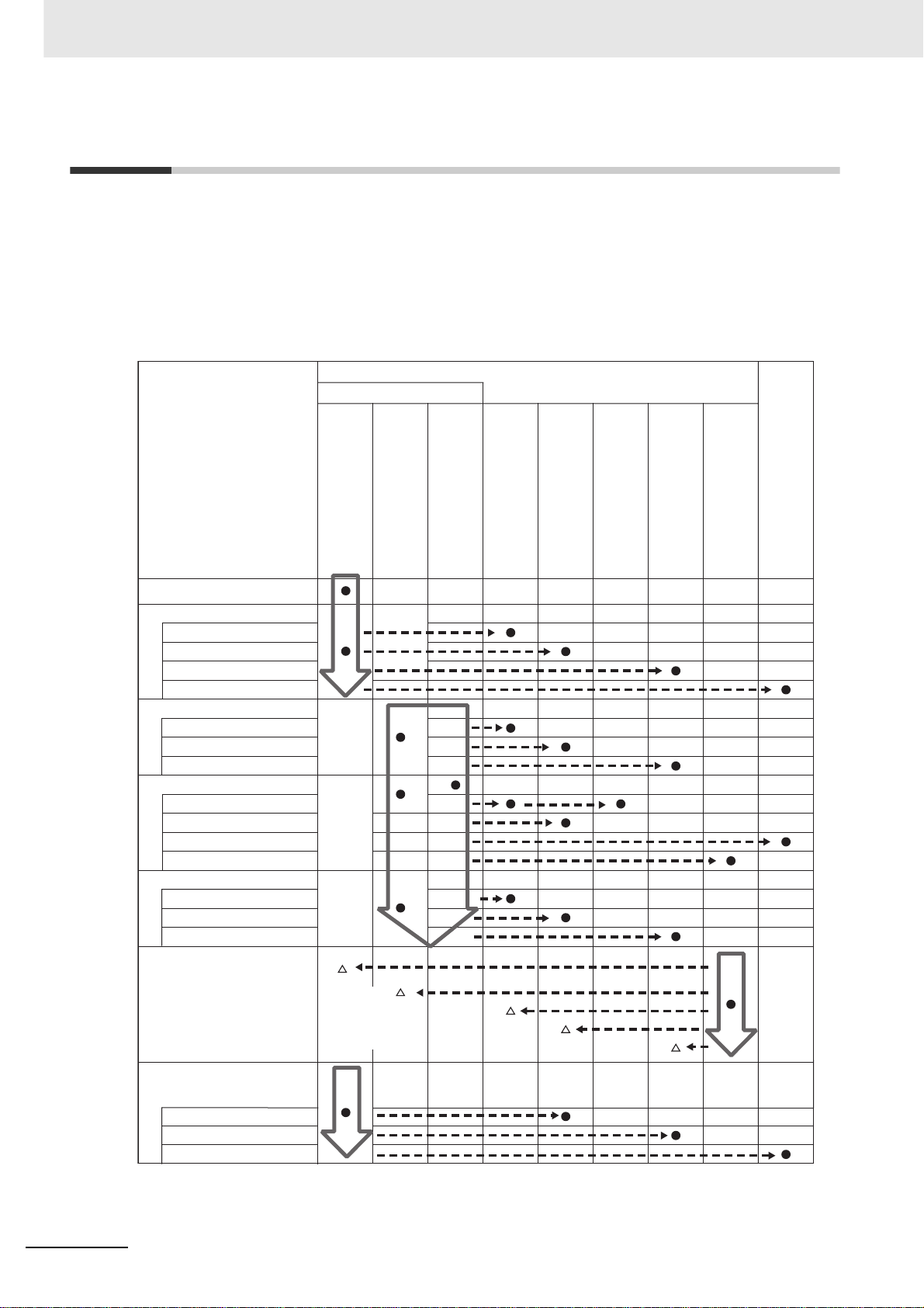
There are three manuals that pr o vide b asic information on the NJ-series CPU Units: the NJ-series CPU
Unit Hardware User’s Manual, the NJ-series CPU Unit Software User’s Manual, and the NJ-series
Instructions Reference Manual.
Most operations are performed from the Sysmac Studio Automation Software. Refer to the Sysmac
Studio Version 1 Operation Manual (Cat. No. W504) for information on the Sysmac Studio.
Other manuals are necessary for specific system configurations and applications.
Read all of the manuals that are relevant to your system configuration and application to make the most
of the NJ-series CPU Unit.
Basic information
NJ-series User’s Manuals
Introduction to NJ-series Controllers
Setting devices and hardware
Using motion control
Using EtherCAT
Using EtherNet/IP
Using CJ-series Units
Software settings
Using motion control
Using EtherCAT
Using EtherNet/IP
Programming
Using motion control
Using EtherCAT
Using CJ-series Units
Programming error processing
Testing operation and debugging
Using motion control
Using EtherCAT
Using EtherNet/IP
Troubleshooting and managing
errors in an NJ-series Controller
NJ-series CPU Unit
Hardware User´s Manual
Use the
relevant
manuals for
references
according to
any error that
occurs.
NJ-series CPU Unit
Software User´s Manual
NJ-series Instructions
Reference Manual
NJ-series CPU Unit Motion
Control User´s Manual
NJ-series CPU Unit Built-in
EtherCAT Port User´s Manual
NJ-series Motion Control
Instructions Reference Manual
NJ-series CPU Unit Built-in
EtherNet/IP Port User´s Manual
NJ-series Troubleshooting Manual
CJ-series Special Unit Operation
Manuals for NJ-series CPU Unit
Maintenance
Using EtherCAT
Using EtherNet/IP
Using CJ-series Units
2
CJ-series High-speed Counter Units Operation Manual for NJ-series CPU Unit(W492)
Page 5
Manual Configuration
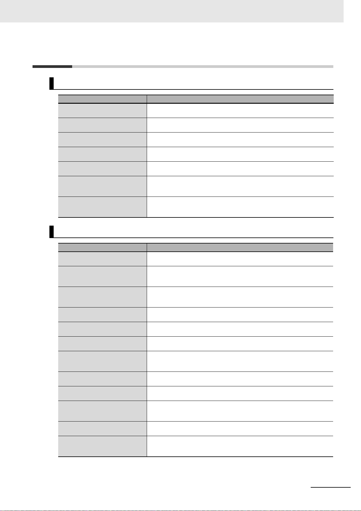
NJ-series CPU Unit Hardware User’s Manual (Cat. No. W500)
Section Description
Section 1
Introduction
Section 2
System Configuration
Section 3
Configuration Units
Section 4
Installation and Wiring
Section 5
Troubleshooting
Section 6
Inspection and Maintenance
Appendices
This section provides an introduction to the NJ-series Controllers and their features,
and gives the NJ-series Controller specifications.
This section describes the system configuration used for NJ-series Controllers.
This section describes the parts and functions of the configuration devices in the NJseries Controller configuration, including the CPU Unit and Configuration Units.
This section describes where and how to install the CPU Unit and Configuration Units
and how to wire them.
This section describes the event codes, error confirmation methods, and corrections
for errors that can occur.
This section describes the contents of periodic inspections, the service life of the Battery and Power Supply Units, and replacement methods for the Battery and Power
Supply Units.
The appendices provide the specifications of the Basic I/O Units, Unit dimensions,
load short-circuit protection detection, line disconnection detection, and measures for
EMC Directives.
Manual Configuration
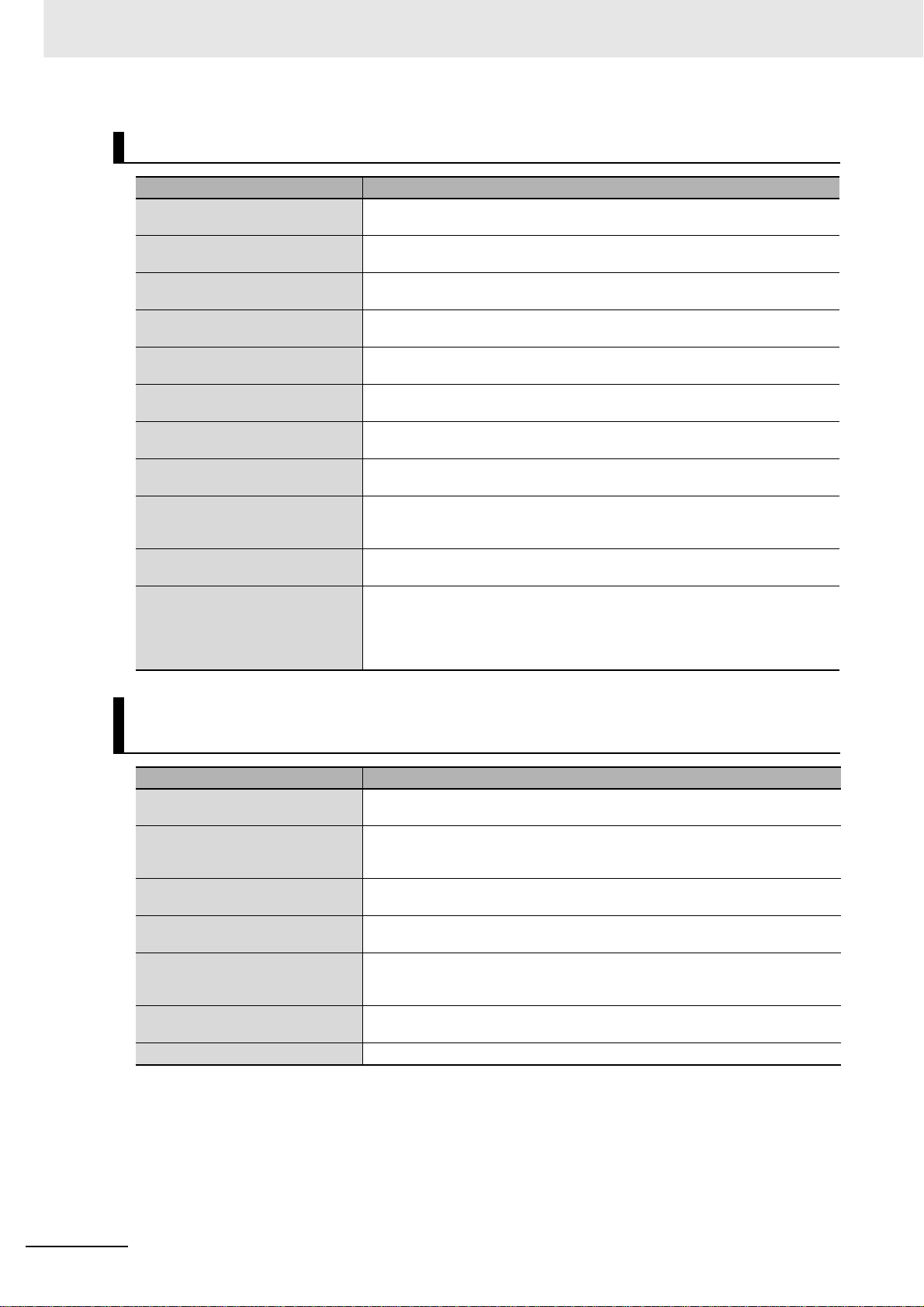
NJ-series CPU Unit Software User’s Manual (Cat. No. W501)
Section Description
Section 1
Introduction
Section 2
CPU Unit Operation
Section 3
I/O Ports, Slave Configuration, and
Unit Configuration
Section 4
Controller Setup
Section 5
Designing Tasks
Section 6
Programming
Section 7
Checking Operation and Actual
Operation
Section 8
CPU Unit Functions
Section 9
Communications Setup
Section 10
Example of Actual Application Procedures
Section 11
Troubleshooting
Appendices
This section provides an introduction to the NJ-series Controllers and their features,
and gives the NJ-series Controller specifications.
This section provides information that is necessary to use the CPU Unit, including
how the CPU Unit works and the operations that it performs depending on the status
of the CPU Unit.
This section describes how to use I/O ports, how to create the slave configuration
and unit configuration and how to assign functions.
This section describes the initial settings of the function modules.
This section describes the task system and types of tasks.
This section describes programming, including the programming languages and the
variables and instructions that are used in programming.
This section describes the items and procedures for checking the operation of an NJseries Controller, including offline debugging procedures.
This section describes the functionality provided by the CPU Unit.
This section describes how to go online with the CPU Unit and how to connect to
other devices.
This section describes the procedures that are used to actually operate an NJ-series
Controller.
This section describes the event codes, error confirmation methods, and corrections
for errors that can occur.
The appendices provide the CPU Unit specifications, task execution times, specifications of individual system-defined variables, data attribute lists, CJ-series Unit memory information, CJ-series Unit memory allocation methods, and version information.
CJ-series High-speed Counter Units Operation Manual for NJ-series CPU Unit(W492)
3
Page 6
Manual Configuration
Sysmac Studio Version 1 Operation Manual (Cat. No. W504)
Section Description
Section 1
Introduction
Section 2
Installation and Uninstallation
Section 3
System Design
Section 4
Programming
Section 5
Online Connections to a Controller
Section 6
Debugging
Section 7
Other Functions
Section 8
Reusing Programming
Section 9
Support Software Provided with the
Sysmac Studio
Section 10
Troubleshooting
Appendices
This section provides an overview and lists the specifications of the Sysmac Studio
and describes its features and components.
This section describes how to install and uninstall the Sysmac Studio.
This section describes the basic concepts for designing an NJ-series System with the
Sysmac Studio and the basic operating procedures.
This section describes how to create programs with the Sysmac Studio.
This section describes how to go online with a Controller.
This section describes how to debug the programs online on the Controller or debug
it offline with the Simulator.
This section describes other functions that are supported by the Sysmac Studio,
including security functions and troubleshooting functions.
This section describes how to reuse the programs that you create with the Sysmac
Studio.
This section describes the Support Software that is provided with the Sysmac Studio.
This section describes the error messages that are displayed when you check a program on the Sysmac Studio and how to correct those errors.
The appendices describe the following:
Driver Installation for Direct USB Cable Connection
Specifying One of Multiple Ethernet Interface Cards
Online Help
Simulation Instructions
CJ-series High-speed Counter Units Operation Manual for NJ-series
CPU Unit (Cat. No. W492) (This Manual)
Section Description
Section 1
Introduction
Section 2
Components, Installation and Wiring
Section 3
Operation and Configuration
Section 4
Exchanging Data with CPU
Section 5
Error Processing, Maintenance and
Inspection
Section 6
Application Examples
Appendices ---
This section describes the functionality and the specifications of the High-speed
Counter Unit, and the operating procedure.
This section describes the details of the components and where and how to install
and wire the High-speed Counter Unit.
This section describes the functionality of the High-speed Counter Unit and how to
configure the Unit.
This section describes the data exchange between the CPU Unit and High-speed
Counter Unit and the definitions of the device variables for CJ-series Unit.
This section describes the troubleshooting procedure, event logs and maintenance
procedure for the High-speed Counter Unit.
This section provides an application example of the High-speed Counter Unit using a
sample program.
4
CJ-series High-speed Counter Units Operation Manual for NJ-series CPU Unit(W492)
Page 7
Manual Configuration
CJ-series High-speed Counter Units Operation Manual (Cat. No.
W401)
Section Description
Section 1
Introduction
Section 2
Components, Installation and Wiring
Section 3
Operation and Configuration
Section 4
Exchanging Data with CPU
Section 5
Error Processing, Maintenance and
Inspection
Section 6
Application Examples
Appendices ---
This section describes the functionality and the specifications of the High-speed
Counter Unit, and the operating procedure.
This section describes the details of the components and where and how to install
and wire the High-speed Counter Unit.
This section describes the functionality of the High-speed Counter Unit and how to
configure the Unit.
This section describes the data exchange between the CPU Unit and High-speed
Counter Unit and data definitions.
This section describes the troubleshooting and maintenance procedures for the Highspeed Counter Unit.
This section provides application examples of the High-speed Counter Unit using program samples.
CJ-series High-speed Counter Units Operation Manual for NJ-series CPU Unit(W492)
5
Page 8
Manual Structure
Manual Structure
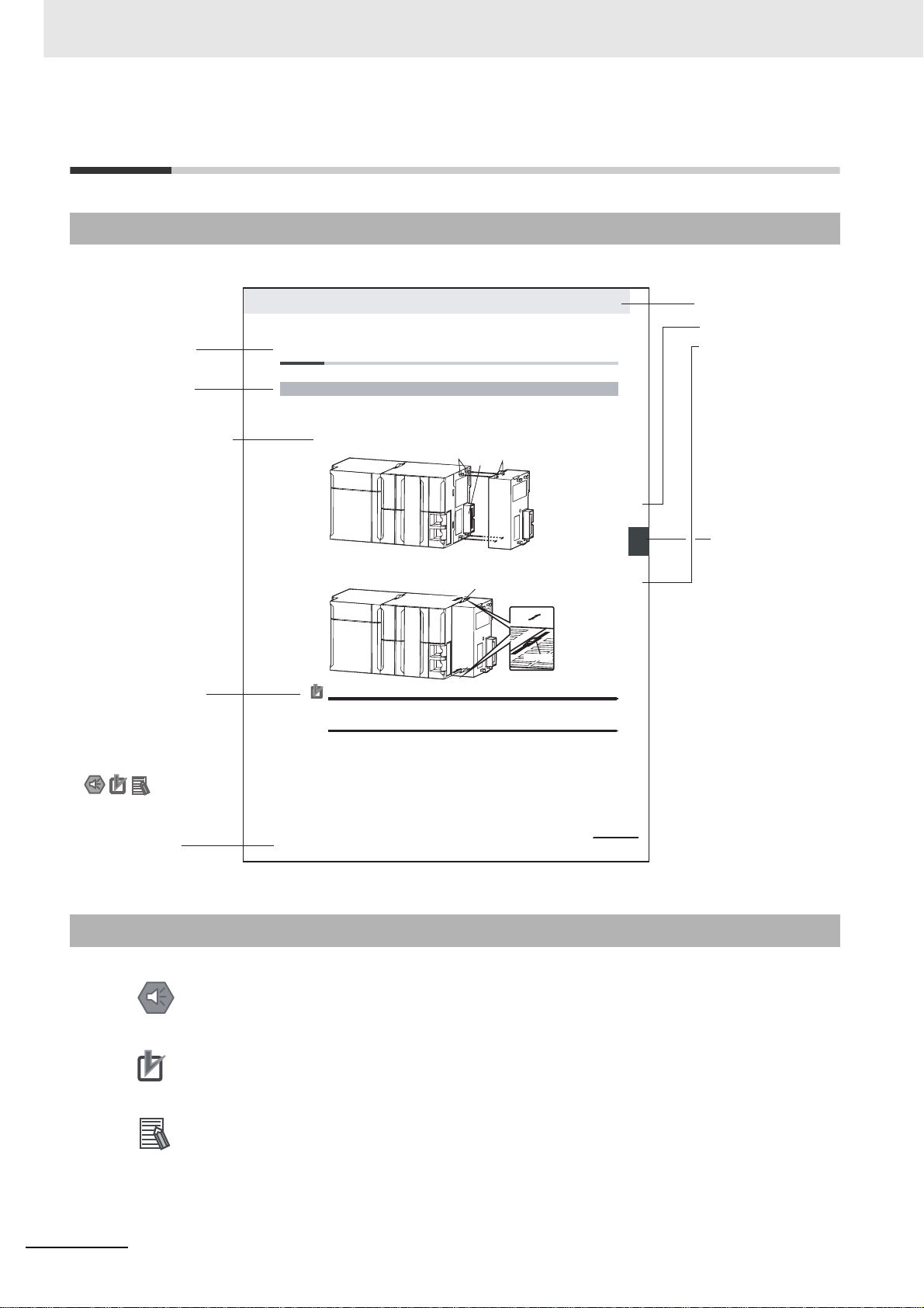
Page Structure
The following page structure is used in this manual.
Level 2 heading
Level 3 heading
A step in a procedure
Indicates a procedure.
Special information
Icons indicate
precautions, additional
information, or reference
information.
4 Installation and Wiring
4-3 Mounting Units
4-3-1 Connecting Controller Components
The Units that make up an NJ-series Controller can b e c on ne ct ed s im p ly by pressing the Uni ts t o g et h e r
and locking the sliders by moving them toward the bac k of th e Un its . Th e E nd Co ver is connected in the
same way to the Unit on the far right side of the Controller.
1 Join the Units so that the connectors fit exactly.
2 The yellow sliders at the top and bottom of each Unit lock the Units together. Move the sliders
toward the back of the Units as shown below until they click into place.
Precautions for Correct UsePrecautions for Correct Use
The sliders on the tops and bottoms of the Powe r Supply Unit, CPU Unit, I/O Units, Special I/O
Units, and CPU Bus Units must be completely locked (until they c l ick into place) after connecting
the adjacent Unit connectors.
Hook
Connector
Move the sliders toward the back
until they lock into place.
Hook holes
Release
Lock
Slider
Level 1 heading
Level 2 heading
Level 3 heading
Gives the current
headings.
stinU gnitnuoM 3-4
4
stnenopmoC rellortnoC gnitcennoC 1-3-4
Page tab
Gives the number
of the main section.
Manual name
Special Information
Special information in this manual is classified as follows:
Precautions for Safe Use
Precautions on what to do and what not to do to ensure safe usage of the product.
Precautions for Correct Use
Precautions on what to do and what not to do to ensure proper operation and performance.
Additional Information
Additional information to read as required.
This information is provided to increase understanding or make operation easier.
Note References are provided to more detailed or related information.
6
NJ-series CPU Unit Hardware User’s Manual (W500)
4-9
This illustration is provided only as a sample. It may not literally appear in this manual.
CJ-series High-speed Counter Units Operation Manual for NJ-series CPU Unit(W492)
Page 9

Precaution on Terminology
In this manual, “download” refers to transferring data from the Sysmac Studio to the physical Controller
and “upload” refers to transferring data from the physical Controller to the Sysmac Studio.
For the Sysmac Studio, synchronization is used to both upload and download data. Here, “synchronize”
means to automatically compare the data for the Sysmac Studio on the computer with the data in the
physical Controller and tra nsfer the data in the direction that is specified by the user.
Manual Structure
CJ-series High-speed Counter Units Operation Manual for NJ-series CPU Unit(W492)
7
Page 10

Manual Structure
8
CJ-series High-speed Counter Units Operation Manual for NJ-series CPU Unit(W492)
Page 11
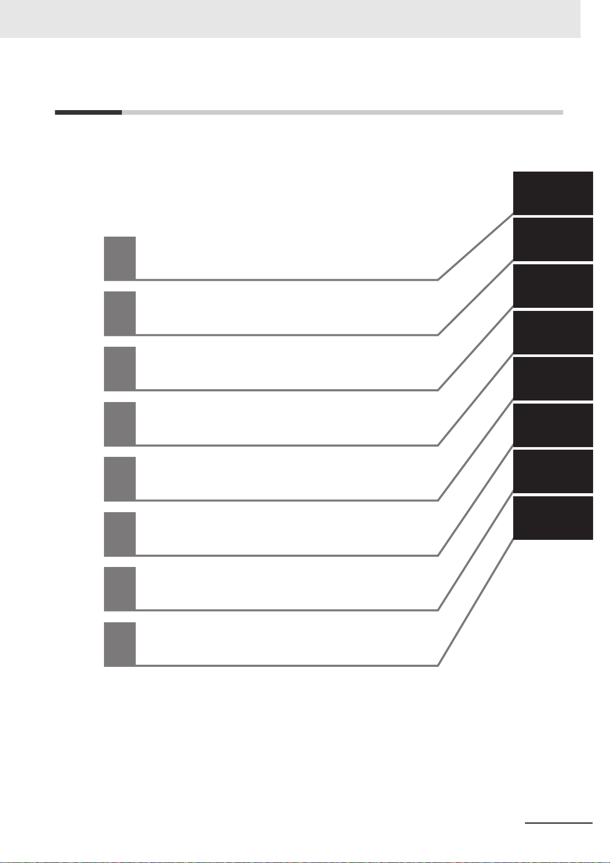
Sections in this Manual
Sections in this Manual
1
2
1
2
3
4
5
6
Introduction
Components, Installation and Wiring
Operation and Configuration
Exchanging Data with CPU
Error Processing, Maintenance and Inspection
Application Examples
3
4
5
6
A
I
A
I
CJ-series High-speed Counter Units Operation Manual for NJ-series CPU Unit(W492)
Appendices
Index
9
Page 12

CONTENTS
CONTENTS
Introduction ...............................................................................................................1
Relevant Manuals......................................................................................................2
Manual Configuration ...............................................................................................3
Manual Structure.......................................................................................................6
Sections in this Manual ............................................................................................9
CONTENTS...............................................................................................................10
Read and Understand this Manual ........................................................................13
Safety Precautions..................................................................................................16
Precautions for Safe Use........................................................................................21
Precautions for Correct Use...................................................................................27
Regulations and Standards....................................................................................30
Unit Versions ...........................................................................................................32
Related Manuals......................................................................................................34
Revision History......................................................................................................35
Section 1 Introduction
1-1 Features and Functions..........................................................................................................1-2
1-2 Basic Configuration ......................................................................................................... .......1-5
1-3 Specifications and Characteristics...................................... ... ... ............................................ 1-7
1-3-1 General Specifications...................................................................... ..........................................1-7
1-3-2 Functional Specifications ............................................................................................................1-8
1-3-3 Input Specifications...................................................................................................................1-10
1-3-4 Output Specifications................................................................................................................1-12
1-4 Quick Start Up Reference Guide .......................................................................................... 1-14
1-4-1 Configuring the High-speed Counter Unit.................................................................................1-17
1-5 Operating Procedure Guidelines.......................................................................................... 1-19
1-6 Application Areas..................................................................................................................1-22
Section 2 Components, Installation and Wiring
2-1 Components and Switch Settings.......................................................................................... 2-2
2-1-1 Components................................................................................................................................2-2
2-1-2 Indicators.....................................................................................................................................2-3
2-1-3 Counter Type Switch...................................................................................................................2-4
2-1-4 Machine Number Switch.............................................................................................................2-5
10
CJ-series High-speed Counter Units Operation Manual for NJ-series CPU Unit(W492)
Page 13

2-2 Installation................................................................................................................................ 2-6
2-2-1 System Configuration Precautions ............................................................................................. 2-6
2-2-2 Installing Units ............................................................................................................................ 2-6
2-3 Wiring ....................................................................................................................................... 2-8
2-3-1 Connector Pin-layout.................................................................................................................. 2-8
2-3-2 Connector Wiring Methods......................................................................................................... 2-9
2-3-3 Important Wiring Considerations ......................................................... ... ..................................2-13
2-3-4 Internal Circuitry .......................................................................................................................2-13
2-3-5 Digital I/O Circuit Configurations...............................................................................................2-15
2-3-6 Counter Input Configurations............................................................... ... .................................. 2-17
Section 3 Operation and Configuration
3-1 Overview................................................................................................................................... 3-2
3-1-1 Summary .................................................................................................................................... 3-2
3-1-2 List of Functions/Allocation Areas by Purpose ...........................................................................3-2
3-2 Counter Types.......................................................................................................................... 3-6
3-2-1 Simple Counter........................................................................................................................... 3-7
3-2-2 Circular Counter........................................................................................................................ 3-10
3-2-3 Linear Counter..........................................................................................................................3-12
3-3 Input Signal Types................................................................................................................. 3-14
3-3-1 Phase Differential .......................................................... .................................... ... ... ................. 3-14
3-3-2 Up & Down Pulse...................................................................................................................... 3-15
3-3-3 Pulse & Direction.................................... .................................................................................. 3-16
3-4 Digital Input Functions.......................................................................................................... 3-17
3-5 Output Control................................... ............................................. ....................................... 3-21
3-5-1 Range Mode............................................................................................................................. 3-23
3-5-2 Comparison Mode ........................................................................................................ ............ 3-29
3-5-3 Manual Output Control............................................................................ ... .. ............................. 3-36
3-5-4 Output Control Configuration......................................... .. ... ..................................... ... .. ............ 3-37
3-6 Reset Counter..................................................................... .......................................... ......... 3-38
3-7 Extra Functions .................................... .... ... ............................................. ............................. 3-40
3-7-1 Programmable Output Pulses................................................................................................... 3-40
3-7-2 Hysteresis................................................................................................................................. 3-42
3-7-3 Noise Filtering........................................................................................................................... 3-43
3-7-4 Initial Counter Value................................................................................... .. ............................. 3-44
CONTENTS
Section 4 Exchanging Data with CPU
4-1 Overview................................................................................................................................... 4-2
4-1-1 Data Flow.................................................................................................................................... 4-2
4-1-2 Unit Restart................................................................................................................................. 4-4
4-1-3 Access from User Program......................................................................................................... 4-5
4-2 Memory Allocation .................................................................................................................. 4-7
4-2-1 Memory Mapping........................................................................................................................ 4-7
4-2-2 Allocating Ranges and Comparison Data................................................................................... 4-7
4-2-3 Details of Device Variables for CJ-series Unit (for input/output)............................................... 4-11
4-2-4 Details of Device Variables for CJ-series Unit (for setting).......................................................4-16
4-2-5 Memory Allocation for Ranges..................................................................................................4-23
4-2-6 Memory Allocation for Comparison data ..................................................................................4-27
CJ-series High-speed Counter Units Operation Manual for NJ-series CPU Unit(W492)
11
Page 14

CONTENTS
Section 5 Error Processing, Maintenance and Inspection
5-1 Error Indicators ....................................................................................................................... 5-2
5-1-1 Errors during initial processing....................................................................................................5-2
5-1-2 Errors during normal operation ...................................................................................................5-3
5-2 Error codes...............................................................................................................................5-4
5-2-1 DM-configuration errors..............................................................................................................5-5
5-2-2 Overflow/Underflow errors...........................................................................................................5-6
5-2-3 Preset Error.............................................................................................................. ...................5-7
5-2-4 System Errors .......................................................... ... ................................................................5-7
5-3 Event Logs ................................................................ ... ............................................. .. .............5-8
5-3-1 Overview of the Event Logs............................. ... .. ... ...................................................................5-8
5-3-2 Error Table...................................................................................................................................5-9
5-3-3 Error Descriptions .....................................................................................................................5-10
5-4 Maintenance and Inspection ................................................................................................5-12
5-4-1 Cleaning....................................................................................................................................5-12
5-4-2 Routine Inspections...................................................................................................................5-12
Section 6 Application Examples
6-1 Flow Control............................................................................................................................. 6-2
Appendices
A-1 Differences of NJ Series from CJ Series...............................................................................A-2
A-1-1 Functional Difference..................................................................................................................A-2
A-1-2 Differences in Access Methods from a User Program ................................................................A-4
A-2 Using Terminal Block Units with Screw-terminals.............................................................A-14
A-3 Description of the Response Time.......................................................................................A-16
A-4 Application Restrictions .......................................................................................................A-17
Index
12
CJ-series High-speed Counter Units Operation Manual for NJ-series CPU Unit(W492)
Page 15

Read and Understand this Manual
Read and Understand this Manual
Please read and understand this manual before using the products. Please consult your OMRON
representative if you have any questions or comments.
Warranty and Limitations of Liability
WARRANTY
OMRON's exclusive warranty is that the products are free from defects in materials and workmanship for a
period of one year (or other period if specified) from date of sale by OMRON.
OMRON MAKES NO WARRANTY OR REPRESENTATION, EXPRESS OR IMPLIED, REGARDING NONINFRINGEMENT, MERCHANTABILITY, OR FITNESS FOR PARTICULAR PURPOSE OF THE
PRODUCTS. ANY BUYER OR USER ACKNOWLEDGES THAT THE BUYER OR USER ALONE HAS
DETERMINED THAT THE PRODUCTS WILL SUITABLY MEET THE REQUIREMENTS OF THEIR
INTENDED USE. OMRON DISCLAIMS ALL OTHER WARRANTIES, EXPRESS OR IMPLIED.
LIMITATIONS OF LIABILITY
OMRON SHALL NOT BE RESPONSIBLE FOR SPECIAL, INDIRECT, OR CONSEQUENTIAL DAMAGES,
LOSS OF PROFITS OR COMMERCIAL LOSS IN ANY WAY CONNECTED WITH THE PRODUCTS,
WHETHER SUCH CLAIM IS BASED ON CONTRACT, WARRANTY, NEGLIGENCE, OR STRICT
LIABILITY.
In no event shall the re sponsibility of OMRON f or any act e xceed the individual price of the product on which
liability is asserted.
IN NO EVENT SHALL OMRON BE RESPONSIBLE FOR WARRANTY, REPAIR, OR OTHER CLAIMS
REGARDING THE PRODUCTS UNLESS OMRON'S ANALYSIS CONFIRMS THAT THE PRODUCTS
WERE PROPERLY HANDLED, STORED, INSTALLED, AND MAINTAINED AND NOT SUBJECT TO
CONTAMINATION, ABUSE, MISUSE, OR INAPPROPRIATE MODIFICATION OR REPAIR.
CJ-series High-speed Counter Units Operation Manual for NJ-series CPU Unit(W492)
13
Page 16

Read and Understand this Manual
Application Considerations
SUITABILITY FOR USE
OMRON shall not be responsible for conformity with any standards, codes, or regulations that apply to the
combination of products in the customer's application or use of the products.
At the customer's request, OMRON will provide applicable third party certification documents identifying
ratings and limitations of use that apply to the products. This info rmation by itself is not sufficient for a
complete determination of the suitability of the products in combination with the end product, machine,
system, or other application or use.
The following are some examples of applications for which particular attention must be given. This is no t
intended to be an e xhaustive list of all possible uses of the products, nor is it in tende d to imp ly th at the uses
listed may be suitable for the products:
• Outdoor use, uses involving potential chemical contamination or electrical interference, or conditions or
uses not described in this manual.
• Nuclear energy control systems, combustion systems, railroad systems, aviation systems, medical
equipment, amusement machines, vehicles, safety equipment, and installations subject to separate
industry or government regulations.
• S ystems, machines, and equipment that could present a risk to life or property.
Please know and observe all prohibitions of use applicable to the produ cts.
NEVER USE THE PRODUCTS FOR AN APPLICATION INVOLVING SERIOUS RISK TO LIFE OR
PROPERTY WITHOUT ENSURING THAT THE SYSTEM AS A WHOLE HAS BEEN DESIGNED TO
ADDRESS THE RISKS, AND THAT THE OMRON PRODUCTS ARE PROPERLY RATED AND
INSTALLED FOR THE INTENDED USE WITHIN THE OVERALL EQUIPMENT OR SYSTEM.
PROGRAMMABLE PRODUCTS
OMRON shall not be responsible for the user's programming of a programmab le product, or any
consequence thereof.
14
CJ-series High-speed Counter Units Operation Manual for NJ-series CPU Unit(W492)
Page 17
Read and Understand this Manual
Disclaimers
CHANGE IN SPECIFICATIONS
Product specifications and accessories may be changed at any time based on improvements and other
reasons.
It is our practice to change model numbers when published ratings or features are changed, or when
significant construction changes are made. However, some specificat ions of the products may be changed
without any notice. When in doubt, special model numbers may be assigned t o fix or establish key
specifications for y our application on your request. Ple ase consult with your OMRON representative at any
time to confirm actual specifications of purchased products.
DIMENSIONS AND WEIGHTS
Dimensions and weights are nominal and are not t o be used for manufacturing purposes, even when
tolerances are shown.
PERFORMANCE DATA
Perf ormance data given in this manual is provided as a guide fo r the user in determining suitability and does
not constitute a warranty. It may represent the result of OMRON's test conditions, and the users must
correlate it to actual application requirements. Actual performance is subject to the OMRON Warranty and
Limitations of Liability.
ERRORS AND OMISSIONS
The information in this manual has been carefully checked and is believed to be accurate; however, no
responsibility is assumed for clerical, typographical, or proofreading errors, or omissions.
CJ-series High-speed Counter Units Operation Manual for NJ-series CPU Unit(W492)
15
Page 18
Safety Precautions
Safety Precautions
Definition of Precautionary Information
The following notation is used in this manual to provide precautions required to ensure safe usage of a
CJ-series High-speed Counter Unit. The safety precautions that are provided are extremely important
to safety. Always read and heed t he information provided in all safety precautions.
The following notation is used.
Indicates a potentially hazardous situation which, if not avoided,
WA RNING
could result in death or serious injury . Additionally, there may be
severe property damage.
Caution
Precautions for Safe Use
Indicates precautions on what to do and what not to do to ensure safe usage of the product.
Precautions for Correct Use
Indicates precautions on what to do and what not to do to ensure proper operation and performance.
Indicates a potentially hazardous situation which, if not avoided,
may result in minor or moderate injury, or property damage.
16
CJ-series High-speed Counter Units Operation Manual for NJ-series CPU Unit(W492)
Page 19
Symbols
Safety Precautions
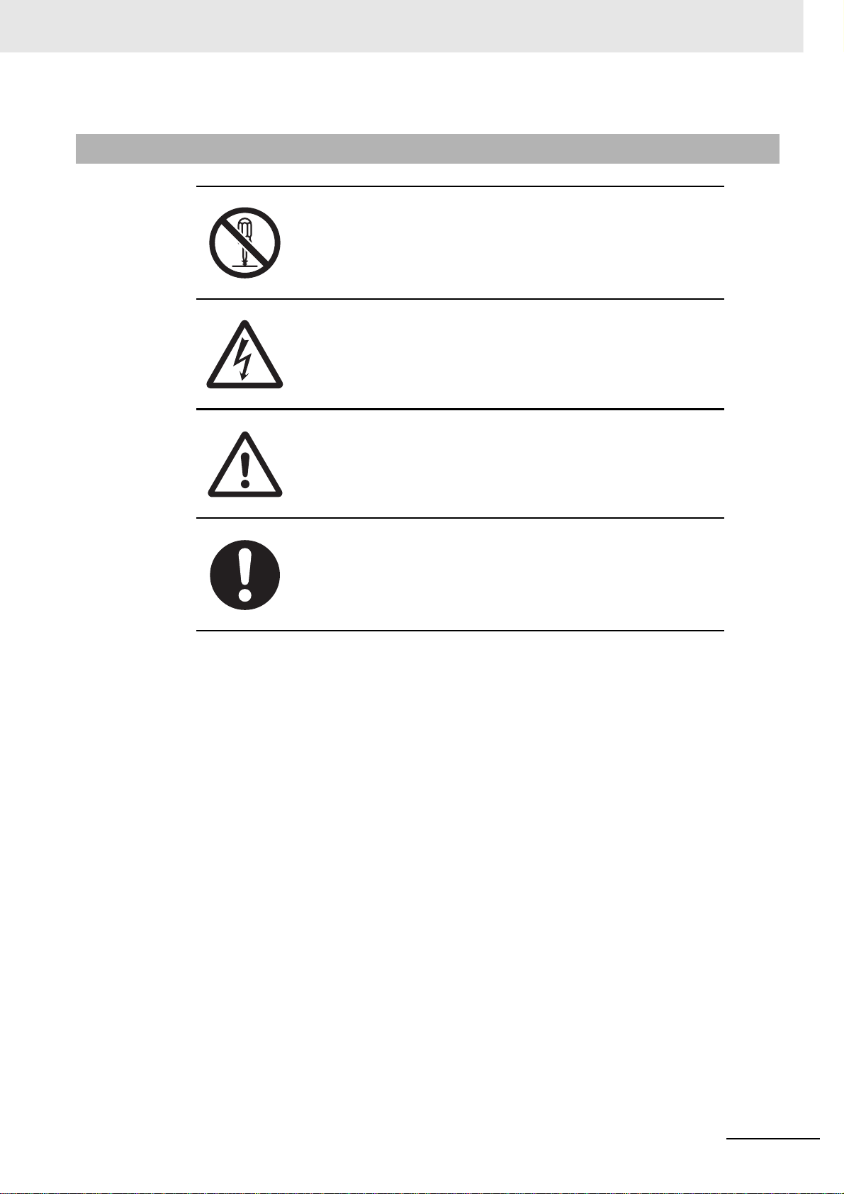
The circle and slash symbol indicates operations that you must not do.
The specific operation is shown in the circle and explained in text.
This example indicates prohibiting disassembly.
The triangle symbol indicates precautions (including warnin gs).
The specific operation is shown in the triangle and explained in text.
This example indicates a precaution for electric shock.
The triangle symbol indicates precautions (including warnin gs).
The specific operation is shown in the triangle and explained in text.
This example indicates a general precaution.
The filled circle symbol indicates operations that you must do.
The specific operation is shown in the circle and explained in text.
This example shows a general precaution for something that you must do.
CJ-series High-speed Counter Units Operation Manual for NJ-series CPU Unit(W492)
17
Page 20
Safety Precautions
During Power Supply
Do not touch any of the terminals or terminal blocks while the power is being
supplied. Doing so may result in electric shock.
Do not attempt to take any Unit apart. In particular, high-voltage parts are
present in the Power Supply Unit while power is supplied or immediately
after power is turned OFF. Touching any of these parts may result in electric
shock. There are sharp parts inside the Unit that may cause injury.
WARNING
Fail-safe Measures
Provide safety measures in external circuits to ensure safety in the system if
an abnormality occurs due to malfunction of the CPU Unit, other Units, or
slaves or due to other external factors affecting operation. Not doing so may
result in serious accidents due to incorrect operation.
Emergency stop circuits, interlock circuits, limit circuits, and similar safety
measures must be provided in external control circuits.
The Controller outputs may remain ON or OFF due to deposition or burning
of the output relays or destruction of the output transistors. As a countermeasure for such problems, external safety measures must be provided to
ensure safe operation of the system.
The CPU Unit will turn OFF all outputs from Basic Output Units in the following cases. The remote I/O slaves will operate according to the settings in the
slaves.
• If an error occurs in the power supply
• If the power supply connection becomes faulty
• If a CPU watchdog timer error or CPU reset occurs
• If a major fault level Controller error occurs
• While the CPU Unit is on standby until RUN mode is entered after the
power is turned ON
External safety measures must be provided to ensure safe operation of the
system in such cases.
18
If external power supplies for slaves or other devices are overloaded or
short-circuited, the voltage will drop, outputs will turn OFF, and the system
may be unable to read inputs. Provide external safety measures in controls
with monitoring of external power supply voltage as required so that the system operates safely in such a case.
CJ-series High-speed Counter Units Operation Manual for NJ-series CPU Unit(W492)
Page 21
WARNING
Fail-safe Measures
Unintended outputs may occur when an error occurs in variable memory or
in memory used for CJ-series Units. As a countermeasure for such problems, external safety measures must be provided to ensure safe operation of
the system.
Provide measures in the communications system and user program to
ensure safety in the overall system even if errors or malfunctions occur in
data link communications or remote I/O communications.
Safety Precautions
If there is interference in remote I/O communications or if a major fault level
error occurs, output status will depend on the products that are used.
Confirm the operation that will occur when there is interference in communications or a major fault level error, and implement safety measures.
Correctly set all of the EtherCAT slaves.
The NJ-series Controller continues normal operation for a certain period of
time when a momentary power interruption occurs. This means that the NJseries Controller may receive incorrect signals from external devices that are
also affected by the power interruption. Accordingly, take suitable actions,
such as external fail-safe measures and interlock conditions, to monitor the
power supply voltage of the external device as required.
You must take fail-safe measures to ensure safety in the event of incorrect,
missing, or abnormal signals caused by broken signal lines, momentary
power interruptions, or other causes. Not doing so may result in serious accidents due to incorrect operation.
Voltage and Current Inputs
Make sure that the voltages and currents that are input to the Units and
slaves are within the specified ranges.
Inputting voltages or currents that are outside of the specified ranges may
cause accidents or fire.
Downloading
Always confirm safety at the destination before you transfer a user program,
configuration data, setup data, device variable s, or values in memory used
for CJ-series Units from the Sysmac Studio. The devices or machines may
perform unexpected operation regardless of the operating mode of the CPU
Unit.
CJ-series High-speed Counter Units Operation Manual for NJ-series CPU Unit(W492)
19
Page 22
Safety Precautions
Application
Do not touch any Unit when power is being supplied or immediately after the
power supply is turned OFF. Doing so may result in burn injury.
Wiring
Be sure that all terminal screws and cable connector screws are tightened to
the torque specified in the relevant manuals. The loose screws may result in
fire or malfunction.
Caution
Online Editing
Execute online editing only after confirming that no adverse effects will be
caused by deviations in the timing of I/O. If you perform online editing, the
task execution time may exceed the task period, I/O may not be refreshed
with external devices, input signals may not be read, and output timing may
change.
20
CJ-series High-speed Counter Units Operation Manual for NJ-series CPU Unit(W492)
Page 23

Precautions for Safe Use
Disassembly and Dropping
• Do not attempt to disassemble, repair, or modify any Units. Doing so may result in malfunction or fire.
• Do not drop any Unit or subject it to abno rmal vibration or shoc k. Doing so ma y r esult in Unit malfunction or burning.
Mounting
• The sliders on the tops and bottoms of the Power Supply Unit, CPU Unit, I/O Units, and other Units
must be completely locked (until they clic k into place) after connecting the adjacent Unit connectors.
Installation
Precautions for Safe Use
• Always connect to a ground of 100 Ω or less when installing the Units. A ground of 100 Ω or less
must be installed when shorting the GR and LG terminals on the Power Supply Unit.
Wiring
• Follow the instructions in this manual to correctly perform wiring.
Double-check all wiring and switch settings before turning ON the power supply.
• Use crimp terminals for wiring.
Do not connect bare stranded wires directly to terminals.
• Do not pull on the cables or bend the cables beyond their natural limit.
Do not place heavy objects on top of the cables or other wiring lines. Doing so may break the cables.
• Mount terminal blocks and connectors only after checking the mou nting location carefully.
• Be sure that the terminal blocks, expansion cables, and other items with locking devices are properly
locked into place.
• Always remove any dustproof labels that are on the top of the Units when they are shipped before
you turn ON the power supply. If the labels are not removed, heat will accumulate and malfunctions
may occur.
• Before you connect a computer to the CPU Unit, disconnect the power supply plug of the computer
from the AC outlet. Also, if the computer has an FG terminal, make the connections so that the FG
terminal has the same electrical potential as the GR terminal on the Power Supply Unit. A difference
in electric potential between the computer and Controller may cause failure or malfunction.
• If the external power supply to an Output Unit or slave has polarity, connect it with the correct polarity. If the polarity is reversed, current may flow in the reverse direction and damage the connected
devices regardless of the operation of the Controller.
Power Supply Design
• Do not exceed the rated supply capacity of the Power Supply Units in the NJ-series Controller. The
rated supply capacities are given in the NJ-series CPU Unit Hardware User’s Manual (Cat. No.
W500).
If the capacity is exceeded, operation may stop, malfunctions may occur, or data may not be backed
up normally for power interruptions.
Use NJ-series Power Supply Units for both the NJ-series CPU Rack and Expansion Racks.
Operation is not possible if a CJ-series Power Supply Unit is used with an NJ-ser ies CPU Unit or an
NJ-series Power Supply Unit is used with a CJ-series CPU Unit.
CJ-series High-speed Counter Units Operation Manual for NJ-series CPU Unit(W492)
21
Page 24

Precautions for Safe Use
• Do not apply voltages or connect loads to the Output Units or slaves in excess of the maximum ratings.
• Surge current occurs when the power supply is tur ned ON. When selecting fuses or breakers for
external circuits, consider the above precaution and allow sufficient margin in shut-off performance.
Refer to the relevant manuals for surge current specifications. Refer to the NJ-series CPU Unit Hard-
ware User’s Manual (Cat. No. W500) for surge current specifications.
• If the full dielectric strength voltage is applied or turned OFF using the s witch on the tester, the generated impulse voltage may damage the Power Supply Unit. Use the adjustment on the tester to gradually increase and decrease the voltage.
• Apply the voltage between the Power Supply Unit's L1 or L2 terminal and the GR terminal when testing insulation and dielectric strength.
• Do not supply AC power from an inverter or other device with a square-wave output. Internal temperature rise may result in smoking or burning. Always input a sinusoidal wave with the frequency that is
given in the NJ-series CPU Unit Hardware User’s Manual (Cat. No. W500).
• Install external breakers and take other safety measures against short-circuiting in external wiring.
Turning ON the Power Supply
• It takes up to approximately 10 to 20 s to enter RUN mode after the power is turned ON. During that
time, outputs will be OFF or will be the values specified in the Unit or slave s ettings, and exter nal
communications cannot be perfor med. Use the RUN output on the Power Supply Unit, for example,
to implement fail-safe circuits so that external devices do not operate incorrectly.
• Configure the external circuits so that the power supply to the control system turns ON only after the
power supply to the Cont roller h as turned ON. If the power supply to the Controller is turned ON after
the control power supply , temporary errors may result in incorrect control system signals because the
output terminals on Ou tput Units may momentarily turn ON when power supply is turned ON to the
Controller.
• If you transfer data from a backup file on an SD Memory Card to the Controller when the power supply is turned ON, proper ly select the da ta groups to transfer. If the data for an unintended data group
is transferred to the Controller, it may cause the equipment to operate unpredictably.
Actual Operation
• Check the user program, data, and parameter settings for proper execution before you use them for
actual operation.
Turning OFF the Power Supply
• Never turn OFF the power supply to the Controller whe n the BUSY indicator is flashing. While the
BUSY indicator is lit, the user program and settings in the CPU Unit are being backed up in the builtin non-volatile memory. This data will not be backed up correctly if the power supply is turned OFF.
Also, a major fault level Controller error will occur the next time you start operation, and operation will
stop.
• Do not turn OFF the power supply or remo ve the SD Memory Card while SD Memory Card access is
in progress (i.e., while the SD BUSY indicator flashes). Data ma y become corrupted, and the Controller will not operate correctly if it uses corrupted data. To remove the SD Memory Card from the CPU
Unit while the power supply is ON, press the SD Memory Card power supply switch and wait for the
SD BUSY indicator to turn OFF before you remove the SD Memory Card.
• Do not disconnect the cable or tur n OFF the power supply to the Controller when downloading data
or the user program from Support Software.
• Always turn OFF the power supply to the Controller before you attempt any of the following.
• Mounting or removing I/O Units or the CPU Unit
• Assembling the Units
• Setting DIP switches or rotary switches
22
CJ-series High-speed Counter Units Operation Manual for NJ-series CPU Unit(W492)
Page 25

Precautions for Safe Use
• Connecting cables or wiring the system
• Connecting or disconnecting the connectors
The Power Supply Unit may continue to supply power to the rest of the Controller for a few seconds
after the power supply turns OFF. The PWR indicator is lit during this time. Confirm that the PWR
indicator is not lit before you perform any of the above.
Operation
• Confirm that no adverse effect will occur in the system before you attempt any of the following.
• Changing the operating mode of the CPU Unit (including changing the setting of the Operating
Mode at Startup)
• Changing the user program or settings
• Changing set values or present values
• Forced refreshing
• Always sufficiently check the safety at the connected devices before you change the settings of an
EtherCAT slave or Special Unit.
• If two different function modules are used together, such as when you use CJ-series Basic Output
Units and EtherCAT slave outputs, take suitable measures in the user program and external controls
to ensure that safety is maintained in the controlled system if on e of the fu nctio n mod ules stop s. The
relevant outputs will stop if a partial fault level error occurs in one of the function modules.
• Always confirm safety at the connected equipment before you reset Controller errors with an event
level of partial fault or higher for the EtherCAT Master Function Module.
When the error is reset, all slaves that were in any state other than Operational state due to a Controller error with an event le vel of partial fault or higher (in which outputs are disabled) will go to Operational state and the outputs will be enabled.
Before you reset all errors, confirm that no Controller errors with an event level of partial fault have
occurred for the EtherCAT Master Function Module.
• Always confirm safety at the connected equipment before you reset Controller errors for a CJ-series
Special Unit. When a Controller error is reset, the Unit where the Controller error with an event level
of observation or higher will be restarted.
Before you reset all errors, confirm that no Controller errors with an event level of observation or
higher have occurred for the CJ-series Special Unit. Observation level events do not appear on the
Controller Error Tab Page, so it is possible that you may restart the CJ-ser ies Special Unit without
intending to do so.
You can check the status of the _CJB_UnitErrSta[0,0] to _CJB_UnitErrSta[3,9] error status variables
on a Watch Tab Page to see if an observation level Controller error has occurred.
Battery Backup
• The user program and initial values for the variables are stored in non-volatile memory in the CPU
Unit. The present values of variables with the Retain attribute and the values of the Holding, DM, and
EM Areas in the memory used for CJ-series Units are backed up by a Battery. If the Battery is not
connected or the Batter y is exhausted, the CPU Un it dete cts a Ba ttery-backup Memory Ch eck Error.
If that error is detected, variables with a Retain attribute are set to their initial values and the Holding,
DM, and EM Areas in memory used for CJ-series Units are cleared to all zeros. Perform thorough
verifications and provide sufficient measures to ensure that the devices perform safe operation for
the initial values of the variables with Retain attributes and the resulting operation.
Debugging
• Forced refreshing ignores the results of user program execution and refreshes I/O with the specified
values. If forced refreshing is used for inputs for which I/O refreshing is not supported, the inputs will
first take the specified values, but they will then be overwritten by the user program. This operation
differs from the force-set/reset functionality of the CJ-series PLCs.
CJ-series High-speed Counter Units Operation Manual for NJ-series CPU Unit(W492)
23
Page 26

Precautions for Safe Use
• You cannot upload or download information for forced refreshing with the Sysmac Studio.
After downloading data that contains forced refreshing, change to RUN mode and then use the Sysmac Studio to perform the operation for forced refreshing.
Depending on the difference in the forced status, the control system may operate unexpectedly.
• Do not specify the same address for the AT specification for more than one variable.
Doing so would allow the same entity to be accessed with different variable names, which would
make the user program more difficult to understand and possibly cause programming mistakes.
General Communications
• When you use data link communications, check the error information that is given in ErrSta (C ontroller Error Status) to make sure that no error has occu rred in the source de vice . Write the user progr am
to use the received data only if there is no error. If there is an error in the source device, the data for
the data link may contain incorrect values.
• Unexpected operat ion may result if inappropriate data link tables are set. Even if appro priate data link
tables have been set, confirm that the controlled system will not be adversely affected before you
transfer the data link tables. The data links star t automatically after the data link tables are transferred.
• All CPU Bus Units are restarted when routing tables are transferred from Support Software to the
CPU Unit. Confirm that the system will not be adversely affected by restarting before you transfer the
routing tables.
• Tag data links will stop between related nodes while tag data link parameters are transferred during
Controller operation. Confirm that the system will not be adversely affected before you transfer the
tag data link parameters.
EtherNet/IP Communications
• All related EtherNet/IP nodes are reset when you transfer settings for the built-in EtherNet/IP port
(including IP addresses and tag data links settings). Confirm that the system will not be adversely
affected by resetting nodes before you transfer the settings.
• If EtherNet/IP tag data links (cyclic communications) are used with a repeating hub, the communications load on the network will increase. This will increase collisions and may prevent stab le comm unications. Do not use repeating hubs on networks where tag data links are used. Use an Ethernet
switch instead.
EtherCAT Communications
• Make sure that the comm unications distance , n umber of nod es connected, and met hod of connect ion
for EtherCAT are within specifications.
Do not connect EtherCAT communications to EtherNet/IP, a standard in-house LAN, or other networks. An overload may cause the network to fail or malfunction.
• Malfunctions or unexpected operation may occur for some combinations of EtherCAT revisions of the
master and slaves. If you disable the revision check in the network settings, use the Sysmac Studio
to check the slave revision settings in the master and the actual slave revisions, and then make sure
that functionality is compatible in the slave manuals or other references. You can check the actual
slave revisions from the Sysmac Studio or on slave nameplates.
• After you transfer the user program, the CPU Unit is restarted and communications with the EtherCAT slaves are cut off. During that period, the slave outputs behave according to the slave settings.
The time that communications are cut off depends on the EtherCAT network configuration. If the
EtherCAT network configuration contains only OMRON EtherCAT slaves, communications are cut off
for a maximum of 45 seconds.
Before you transfer the user program, confirm that the system will not be adversely affected.
24
CJ-series High-speed Counter Units Operation Manual for NJ-series CPU Unit(W492)
Page 27

Precautions for Safe Use
• If the Fail-soft Operation parameter is set to stop operation, process data communications will stop
for all slaves when an EtherCAT communications error is detected in a slave. For this reason, if
Servo Drives are connected, the Servos for all axes will be turned OFF. Make sure that the Fail-soft
Operation parameter setting results in safe operation when a device error occurs.
• EtherCAT communications are not always established immediately after the power supply is tur ned
ON. Use the system-defined variables in t he user prog ra m to confirm that communication s are established before attempting control operations.
• If frames sent to EtherCAT slaves are lost due to noise or other causes, slave I/O data is not communicated, and the intended operation is sometimes not achieved. If noise countermeasures are
required, use the _EC_InDataInvalid (Input Data Disable) system-defined variable as an interlock
condition in the user program.
Refer to the NJ-series CPU Unit Built-in EtherCAT Port User’s Manual (Cat. No. W505) for details.
The slave outputs behave according to the slave settings. Refer to the manuals for the slaves for
details.
• When an EtherCAT slave is disconnected, communications will stop and control of the outputs will be
lost not only for the disconnected slave, but for all slaves connected after it. Confirm that the system
will not be adversely affected before you disconnect a slave.
• If you disconnect the cable from an EtherCAT slave to disconnect it from the network, any current
communications frames may be lost. If frames are lost, slave I/O data is not communicated, and the
intended operation is sometimes not achieved. Perform the following processing for a slave that
needs to be replaced.
Program the _EC_InDataInvalid (Input Data Disable) system-defined variable as an interlock con-
dition.
Set the Impermissible Number of Continuous Timeouts setting in the EtherCAT master to at least
2.
Refer to the NJ-series CPU Unit Built-in EtherCAT Port User’s Manual (Cat. No. W505) for details.
Motion Control
• Confirm the axis number carefully before you perform an MC Test Run.
• The motor is stopped if communications are interrupted between the Sysmac Studio and the CPU
Unit during an MC Test Run. Connect the communications cable between the computer and CPU
Unit securely and confirm that the system will not be adversely affected before you perfor m an MC
Test Run.
• Always execute the Save Cam Table instruction if you change any of the cam data from the user program in the CPU Unit or from the Sysmac Studio. If the cam data is not saved, the previous condition
will be restored when the power is turned ON again, possibly causing unexpected machine operation.
• The positive drive prohibit input (POT), negative drive prohibit input (NOT), and home proximity input
(DEC) of the Servo Drive are used by the MC Function Module as the positive limit input, negative
limit input, and home proximity input. Make sure that the signal widths for all of these input signals
are longer than the control period of the MC Function Module. If the input signal widths are shorter
than the control period, the MC Function Module ma y not be ab le to detect the input sig nals , resulting
in incorrect operation.
Battery Replacement
• The Battery may leak, rupture, heat, or ignite. Never short-circuit, charge, disassemble, heat, or
incinerate the Battery or subject it to strong shock.
• Dispose of any Battery that has been dropped on the floor or otherwise subjected to excessive
shock. Batteries that have been subjected to shock may leak if they are used.
• UL standards require that only an experienced engineer replace the Battery. Make sure that an experienced engineer is in charge of Battery replacement.
CJ-series High-speed Counter Units Operation Manual for NJ-series CPU Unit(W492)
25
Page 28

Precautions for Safe Use
• Apply power for at least five minutes before changing the Battery. Install a new Battery within five
minutes (at 25°C) of turning OFF the power supply. If power is not supplied for at least 5 minutes, the
saved data may be lost.
Unit Replacement
• We recommend replacing the Battery with the power turned OFF to prevent the CPU Unit’s sensitive
internal components from being damaged by static electricity and to prevent malfunctions. The Battery can be replaced without turning OFF the power supply. To do so, always touch a grounded piece
of metal to discharge static electricity from your body before you start the procedure.
After you replace the Battery, connect the Sysmac Studio and clear the Low Battery Voltage error.
• Make sure that the required data, including the user program, configurations, settings, variables, and
memory used for CJ-series Units, is transferred to a CPU Unit that was replaced and to exter nally
connected devices before restarting operation.
Be sure to include the routing tables, networ k parameters, and other CPU Bus Unit data, which are
stored in the CPU Unit.
Disposal
• Dispose of the product and Batteries according to local ordinances as they apply.
• The following information must be displa yed for all products that contain primary lithium batteries with
a perchlorate content of 6 ppb or higher when shipped to or transported through the State of California, USA.
Perchlorate Material - special handling may apply.
See www.dtsc.ca.gov/hazardouswaste/perchlorate.
• The CPU Unit contains a primary lithium battery with a perchlorate content of 6 ppb or higher. Place
the above infor mation on the individual boxes and shipping boxes when shipping finished products
that contain a CPU Unit to the State of California, USA.
26
CJ-series High-speed Counter Units Operation Manual for NJ-series CPU Unit(W492)
Page 29

Precautions for Correct Use
Storage, Mounting, and Wiring
• Do not operate or store the Controller in the following locations. Operation may stop or malfunctions
may occur.
• Locations subject to direct sunlight
• Locations subject to temperatures or humidity outside the range specified in the specifications
• Locations subject to condensation as the result of severe changes in temperature
• Locations subject to corrosive or flammable gases
• Locations subject to dust (especially iron dust) or salts
• Locations subject to exposure to water, oil, or chemicals
• Locations subject to shock or vibration
• Take appropriate and sufficient countermeasures when installing the Controller in the following locations.
• Locations subject to strong, high-freq uency noise
• Locations subject to static electricity or other forms of noise
• Locations subject to strong electromagnetic fields
• Locations subject to possible exposure to radioactivity
• Locations close to power lines
• Before touching a Unit, be sure to first touch a grounded metallic object in order to discharge any
static build-up.
• Install the Controller away from sources of heat and ensure proper ventilation. Not doing so may
result in malfunction, in operation stopping, or in burning.
• An I/O bus check error will occur and the Controller will stop if an I/O Connecting Cable’s connector is
disconnected from the Rack. Be sure that the connectors are secure.
• Do not allow foreign matter to enter the openings in the Unit. Doing so may result in Unit burning,
electric shock, or failure.
• Do not allow wire clippings, shavings, or other foreign material to enter any Unit. Otherwise, Unit
burning, failure, or malfunction may occur. Cover the Units or take other suitable countermeasures,
especially during wiring work.
• For EtherCAT and EtherNet/IP, use the connection methods and cables that are specified in the NJ-
series CPU Unit Built-in EtherCAT Port User’s Manual (Cat. No. W505) and the NJ-series CPU U nit
Built-in EtherNet/IP Port User’s Manual (Cat. No. W506). Otherwise, communications may be faulty.
• Use the rated power supply voltage for the Power Supply Units. Take appropriate measures to
ensure that the specified power with the rated voltage and frequency is supplied in places where the
power supply is unstable.
• Make sure that the current capacity of the wire is sufficie nt. Otherwise, excessive heat may be generated. When cross-wiring terminals, the total current for all the terminals will flow in the wire. When
wiring cross-overs, make sure that the current capacity of each of the wires is not exceeded.
• Do not touch the terminals on the Power Supply Unit immediately after turning OFF the power supply. Residual voltage may cause electrical shock.
• If you use reed switches for the input contacts for AC Input Units, use switches with a current capacity of 1 A or greater.
If the capacity of the reed switches is too low, surge current may fuse the contacts.
Precautions for Correct Use
CJ-series High-speed Counter Units Operation Manual for NJ-series CPU Unit(W492)
27
Page 30

Precautions for Correct Use
Error Processing
• In applications that use the results of instructions th at r ead the er ror st at us, consider the affect on the
system when errors are detected and program error processing accordingly. For example, even the
detection of a minor error, such as Battery replacement during operation, can affect the system
depending on how the user program is written.
• If you change the event level of a Controller error, the output status when the error occurs may also
change. Confirm safety before you change an event le vel.
Restoring and Automatically Transferring Data
• When you edit the restore command file or the automatic transfer command file, do not change anything in the file except for the “yes” and “no” specifications for the selectable data groups. If you
change anything else in the file, the Controller may perform unexpected operation when you restore
or automatically transfer the data.
Unit Replacement
• If you replace a CPU Bus Unit or Special I/O Unit, refer to operation manual for the Unit for information on the data required for individual Units and redo the necessary settings.
• The absolute encoder home offset is backed up with a Battery in the CPU Unit.
When you change the combination of the CPU Unit and Servo motor, e.g., when you add or replace a
Servomotor, define home again.
To restore the information without changing the CPU Unit-Servomotor combination, remove the
absolute encoder home offset from the data to restore.
Task Settings
• If a Task Period Exceeded error occurs, shorten the programs to fit in the task period or increase the
setting of the task period.
Motion Control
• Use the system-defined variable in the user program to confirm that EtherCAT communications are
established before you attempt to execute motion control instructions. Motion control instructions are
not executed normally if EtherCAT communications are not established.
• Use the system-defined variables to monitor for errors in communications with the slaves that are
controlled by the motion control function module. Motio n control instructions are not executed normally if an error occur in slave communications.
• Before you start an MC Test Run, make sure that the operation parameters are set correctly.
• Do not download motion control settings during an MC Test Run.
28
EtherCAT Communications
• Do not disconnect the EtherCAT slave cables during operation. The outputs will become unstable.
• Set the Servo Drives to stop operation if an error occurs in EtherCAT communications between the
Controller and a Servo Drive.
• Make sure that all of the slaves to be restored are participating in the network before you reset a Network Configuration Verification Error, Process Data Communications Error, or Link OFF Error in the
EtherCAT Master Function Module. If any slave is not participating when any of these errors is reset,
the EtherCAT Master Function Module may access sla ve with a different node address than the specified node address or the error may not be reset correctly.
CJ-series High-speed Counter Units Operation Manual for NJ-series CPU Unit(W492)
Page 31

Precautions for Correct Use
Battery Replacement
• Be sure to install a replacement Battery within two years of the productio n date shown on the Battery
label.
• Turn ON the power after replacing the Battery for a CPU Unit that has been unused for a long time.
Leaving the CPU Unit unused again without turning ON the power even once after the Battery is
replaced may result in a shorter Battery life.
• When you replace the Battery, use the CJ1W-BAT01 Battery Set.
SD Memory Cards
• Insert the SD Memory Card all the way.
• Do not turn OFF the power supply to the Contr oller during SD Memo ry Card access. The files may be
corrupted.
If there is a corrupted file in the SD Memory Card, the file is automatically deleted by the restoration
function when the power supply is turned ON.
CJ-series High-speed Counter Units Operation Manual for NJ-series CPU Unit(W492)
29
Page 32

Regulations and Standards
Regulations and Standards
Conformance to EC Directives
Applicable Directives
• EMC Directives
• Low Voltage Directive
Concepts
z EMC Directive
OMRON devices that comply with EC Directives also conform to the related EMC standards so that
they can be more easily built into other devices or the overall machine. The actual products have
been checked for conformity to EMC standards.*
Whether the products conform to the standards in the system used by the customer, however, must
be checked by the customer. EMC-related perf ormance of the OMRON devices that comply with EC
Directives will vary depending on the configuration, wiring, and other conditions of the equipment or
control panel on which the OMRON devices are installed. The customer must, therefore, perform
the final check to confirm that devices and the overall machine conform to EMC standards.
* Applicable EMC (Electromagnetic Compatibility) standards are as follows:
EMS (Electromagnetic Susceptibility): EN 61131-2 and EN 61000-6-2
EMI (Electromagnetic Interference): EN 61131-2 and EN 61000-6-4 (Radiated emission: 10-m regulations)
z Low Voltage Directive
Always ensure that devices operating at voltages of 50 to 1,000 VAC and 75 to 1,500 VDC meet the
required safety standards. The applicable directive is EN 61131-2.
z Conformance to EC Directives
The NJ-series Controllers comply with EC Directives. To ensure that the machine or device in which
the NJ-series Controller is used complies with EC Directives, the Controller must be installed as follows:
• The NJ-series Controller must be installed within a cont rol panel.
• You must use reinforced insulation or double insulation for the DC power supplies connected to
DC Power Supply Units and I/O Units.
• NJ-series Controllers that comply with EC Directiv es al so conform to the Common Emission Standard (EN 61000-6-4). Radiated emission characteristics (10-m regulations) may var y depending
on the configuration of the control panel used, other devices connected to the control panel, wiring, and other conditions.
You must therefore con firm that the o verall machine or equipment complies with EC Directives.
30
CJ-series High-speed Counter Units Operation Manual for NJ-series CPU Unit(W492)
Page 33

Conformance to Shipbuilding Standards
The NJ-series Controllers comply with the following shipbuilding standards. Applicability to the shipbuilding standards is based on certain usage conditions . I t may not be possible to use the product in
some locations. Contact your OMRON representative before attempting to use a Controller on a
ship.
Usage Conditions for NK and LR Shipbuilding Standards
• The NJ-series Controller must be installed within a control panel.
• Gaps in the door to the control panel must be completely filled or covered with gaskets or other
material.
• The following noise filter must be connected to the power supply line.
Noise Filter
Manufacturer Model
Cosel Co., Ltd. TAH-06-683
Regulations and Standards
Trademarks
• Sysmac and SYSMAC are trademarks or registered trademarks of OMRON Corporation in Japan
and other countries for OMRON factory automation products.
• Windows, Windows 98, Windows XP, Windows Vista, and Windows 7 are registered trademarks of
Microsoft Corporation in the USA and other countries.
•EtherCAT is registered trademark and patented technology, licensed by Beckhoff Automation
GmbH, Germany.
• The SD logo is a trademark of SD-3C, LLC.
Other company names and product names in this document are the trademarks or registered trademarks of their respective companies.
CJ-series High-speed Counter Units Operation Manual for NJ-series CPU Unit(W492)
31
Page 34

Unit Versions
Unit Versions
Unit Versions
A “unit version” has been introduced to manage CPU Units in the NJ Series according to differences in
functionality accompanying Unit upgrades.
Notation of Unit Versions on Products
The unit version is given on the ID information label of the products for which unit versions are managed, as shown below.
Example for NJ-series NJ501-@@@@ CPU Unit:
ID information label
Unit model Unit version
NJ501 - 1500 Ver.1.@@
PORT1 MAC ADDRESS: @@@@@@@@@@@@
PORT2 MAC ADDRESS: @@@@@@@@@@@@
Lot No. DDMYY @ xxxx
Lot number and serial number MAC address
The following information is provided on the ID information label.
Item Description
Unit model Gives the model of the Unit.
Unit version Gives the unit version of the Unit.
Lot number and
serial number
MAC address Gives the MAC address of the built-in port on the Unit.
Gives the lot number and serial number of the Unit.
DDMYY: Lot number, @: For use by OMRON, xxxx: Serial number
“M” gives the month (1 to 9: January to September, X: October, Y: November, Z: December)
32
Confirming Unit Versions with Sysmac Studio
You can use the Unit Production Information on the Sysmac Studio to chec k t he unit version of the CPU
Unit, CJ-series Special I/O Units, CJ-series CPU Bus Units, and EtherCAT slaves. The unit versions of
CJ-series Basic I/O Units cannot be checked from the Sysmac Studio.
z CPU Unit and CJ-series Units
1 Double-click CPU/Expansion Racks under Configurations and Setup in the Multiview
Explorer. Or, right-click CPU /Expansion Racks under Configurations and Setup and select
Edit from the menu.
The Unit Editor is displayed for the Controller Configurations and Setup layer.
CJ-series High-speed Counter Units Operation Manual for NJ-series CPU Unit(W492)
Page 35

Unit Versions
2 Right-click any open space in the Unit Editor and select Production Information.
The Production Information Dialog Box is displayed.
Simple Display Detailed Display
In this example, “Ver.1.00” is displayed next to the unit model.
The following items are displayed.
CPU Unit CJ-series Units
Unit model
Unit version
Lot number
Unit model
Unit version
Lot number
Rack number, slot number, and unit number
z EtherCAT Slaves
1 Double-click EtherCAT under Configurations and Setup in the Multiview Explorer. Or, right-
click EtherCAT under Configurations and Setup and select Edit from the menu.
The EtherCAT Configuration Tab Page is displayed for the Controller Configurations and Setup
layer.
2 Right-click the master in the EtherCAT Configurations Editing Pane and select Display Produc-
tion Information.
The Production Information Dialog Box is displayed.
The following items are displayed.
Node address
Type information*
Serial number
* If the model number cannot be determined (such as when there is no ESI file), the vendor ID, product
code, and revision number are displayed.
CJ-series High-speed Counter Units Operation Manual for NJ-series CPU Unit(W492)
33
Page 36

Related Manuals
Related Manuals
The following manuals are related to the NJ-series Controllers. Use these manuals for reference.
Manual name Cat. No. Model numbers Application Description
NJ-series CPU Unit
Hardware User’s Manual
NJ-series CPU Unit Software User’s Manual
Sysmac Studio V ersion 1
Operation Manual
CJ-series High-speed
Counter Units Operation
Manual for NJ-series
CPU Unit (This Manual)
CJ-series High-speed
Counter Units Operation
Manual
W500 NJ501-@@@@
NJ301-@@@@
W501 NJ501-@@@@
NJ301-@@@@
W504 SYSMAC-
SE2@@@
W492 CJ1W-CT021 Learning about the func-
W401 CJ1W-CT021 Learning about the func-
Learning the basic specifications of the NJ-series
CPU Units, including introductory information,
designing, installation, and
maintenance. Mainly hardware information is provided.
Learning how to program
and set up an NJ-series
CPU Unit. Mainly software
information is provided.
Learning about the operating procedures and functions of the Sysmac Studio.
tions and usage of CJseries High-speed Counter
Units for using it in an NJseries configuration.
tions and usage of CJseries High-speed Counter
Units.
An introduction to the entire NJ-series system is
provided along with the following information on
the CPU Unit.
• Features and system configuration
• Introduction
• Part names and functions
• General specifications
• Installation and wiring
• Maintenance and inspection
Use this manual together with the NJ-series
CPU Unit Software User’s Manual (Cat. No.
W501).
The following information is provided on a Controller built with an NJ501 CPU Unit.
• CPU Unit operation
• CPU Unit features
• Initial settings
• Programming based on IEC 61131-3 language specifications
Use this manual together with the NJ-series
CPU Unit Hardware User’s Manual (Cat. No.
W500).
Describes the operating procedures of the Sysmac Studio.
The functions and usage of the CJ-series Highspeed Counter Unit for using it in an NJ-series
configuration are described.
The functions and usage of the CJ-series Highspeed Counter Unit for using it in a CJ-series
configuration are described.
34
CJ-series High-speed Counter Units Operation Manual for NJ-series CPU Unit(W492)
Page 37

Revision History
A manual revision code appears as a suffix to the catalog number on the front and back covers of the
manual.
Revision History
Cat. No.
Revision code Date Revised content
01 July 2011 Original production
02 March 2012 Corrected errors.
03 August 2012 Made changes accompanying release of unit version 1.03 of
W492-E1-03
Revision code
the CPU Unit.
CJ-series High-speed Counter Units Operation Manual for NJ-series CPU Unit(W492)
35
Page 38

Revision History
36
CJ-series High-speed Counter Units Operation Manual for NJ-series CPU Unit(W492)
Page 39

Introduction
This section gives specifications of the CJ1W-CT021 and a brief description of the
functions and features of the Unit and the areas of application.
1-1 Features and Functions . . . . . . . . . . . . . . . . . . . . . . . . . . . . . . . . . . . . . . . . . 1-2
1-2 Basic Configuration . . . . . . . . . . . . . . . . . . . . . . . . . . . . . . . . . . . . . . . . . . . . 1-5
1-3 Specifications and Characteristics . . . . . . . . . . . . . . . . . . . . . . . . . . . . . . . 1-7
1-3-1 General Specifications . . . . . . . . . . . . . . . . . . . . . . . . . . . . . . . . . . . . . . . . . . . 1-7
1-3-2 Functional Specifications . . . . . . . . . . . . . . . . . . . . . . . . . . . . . . . . . . . . . . . . . 1-8
1-3-3 Input Specifications . . . . . . . . . . . . . . . . . . . . . . . . . . . . . . . . . . . . . . . . . . . . 1-10
1-3-4 Output Specifications . . . . . . . . . . . . . . . . . . . . . . . . . . . . . . . . . . . . . . . . . . . 1-12
1-4 Quick Start Up Reference Guide . . . . . . . . . . . . . . . . . . . . . . . . . . . . . . . . . 1-14
1-4-1 Configuring the High-speed Counter Unit . . . . . . . . . . . . . . . . . . . . . . . . . . . 1-17
1-5 Operating Procedure Guidelines . . . . . . . . . . . . . . . . . . . . . . . . . . . . . . . . 1-19
1-6 Application Areas . . . . . . . . . . . . . . . . . . . . . . . . . . . . . . . . . . . . . . . . . . . . . 1-22
1
CJ-series High-speed Counter Units Operation Manual for NJ-series CPU Unit(W492)
1-1
Page 40

1 Introduction
1-1 Features and Functions
CT021
RUN ERC ERH
CH1 A B Z I0 O0
CH2 A B Z I1 O1
20 20
CN1
1 1
B A
3
4
2
1
0
9
8
3
2
1
0
9
8
MODE
5
6
7
4
5
6
7
The CJ1W-CT021 High-speed Counter Unit is equipped with 2 Counters and counts over a maximum
binary range of 32 -bits. Accepting input pulse frequencies of up t o 500 kHz allows precise control of
fast motions. The Unit's bi-directional counting ability enables detecting movement in either direction.
Each Counter of the Unit can be configured independently. The Unit is equipped with 2 Digital Inputs, 2
Digital Outputs and 30 Soft Outputs. A maximum response time of 0.5 ms guarantees high-speed
closed loop control of applications.
z Freely Configurable
You can make a flexible setting on this High-speed Counter Unit to suit the user application.
z Counter Type
Configuring the Unit starts with choosing one out of 3 Counter Types:
• Simple Counter (refer to 3-2-1 Simple Counter)
• Circular Counter (refer to 3-2-2 Circular Counter)
• Linear Counter (refer to 3-2-3 Linear Counter)
By default all Counters are set to Simple Counter for which no configuration settings have to be
made, enabling every Counter to count pulses directly after the Unit has been powered up. For all
Counter Types the full counting range is available. Circular and Linear Counters can be configured
with Special Unit settings according to the application to control.
z Input Signal Type
Depending on the type of input signal that your application requires, for every Counter a choice can
be made out of three input signal types:
• Phase Differential Inputs (multiplication by either 1, 2 or 4)
(refer to 3-3-1 Phase Differential)
• Up/Down Pulse Inputs (refer to 3-3-2 Up & Down Pulse)
• Pulse & Direction Inputs (refer to 3-3-3 Pulse & Direction)
1-2
CJ-series High-speed Counter Units Operation Manual for NJ-series CPU Unit(W492)
Page 41

1 Introduction
z Digital Input Function
This Unit supports two Digital Inputs (I0 and I1) which can be allocated freely for each Counter. A
function can be selected from among eight types of functions and allocated for each Digital Input
according to the user application.
Function allocation makes it possible to use the Dig ital Inputs together with ga tes, presets, resets,
etc. (Refer to 3-4 Digital Input Functions).
1-1 Features and Functions
z Digital Output Control
To control the Outputs, the Unit can be configured in one of the two following Output Control Modes:
• Range Mode (refer to 3-5-1 Range Mode)
• Comparison Mode (refer to 3-5-2 Comparison Mode)
In Range Mode, up to 32 Ranges can be applied to individual Counters. Every Range can control a
maximum of 32 Outputs. An Output is turned ON when the Counter is in the corresponding Range.
In Comparison Mode, up to 32 comparison data can be applied to individual Counters. Depending
on the direction of counting, an Output can be set or reset (configurable) on reaching the Comparison Value. Every Comparison Value can control up to 32 Outputs.
Furthermore, by setting and resetting I/O ports for output data in the CPU Unit, Digital Outpu t can be
controlled manually (refer to 3-5-3 Manual Output Control).
You can set to hold the output in the previous status or to put it into the defined status for when the
CPU Unit Operating Mode is changed from RUN Mode to PROGRAM Mode, when an I/O bus check
error occurs or when an overflow/underflow error occurs (refer to 3-5-4 Output Control Configura-
tion).
z Resetting Counter Value
Resetting of the Counter Value can be freely configured depending on the application needs. The
following sources can trigger a reset:
• Software bit in the PLC
• Z-Input
• Digital Input (that is configured as a Reset Input)
1
To enable resetting a Counter Value, an Digital Input must be configured as Enable Reset Input
and/or the Software Enable Reset bit can be used (refer to 3-6 Reset Counter).
z Programmable Output Pulses
The timing characteristics of the Digital Outputs can be modified, depending on the requirements of
the application as follows (refer to 3-7-1 Programmable Output Pulses):
• Output Turn ON Delay [1 ms to 9999 ms], to delay turning ON an Output
• Output Pulse Duration [1 ms to 9999 ms], to generate an Output pulse of the specified duration
z Hysteresis
For Counters in Range Mode a hysteresis can be configured [1 to 255 counts], to prevent Outputs
from toggling due to unwanted oscillating of encoding equipment (e.g. rotary incremental encoder)
around the upper/lower limits. Refer to 3-7 -2 Hysteresis.
CJ-series High-speed Counter Units Operation Manual for NJ-series CPU Unit(W492)
1-3
Page 42

1 Introduction
z Noise Filtering
For the purpose of suppressing noise on the signa l lines A and B of every Counter and on the Digital
Input lines, noise filters can be used.
The cut-off frequencies for th e signal lines, A and B can be set to:
• 10 kHz
• 50 kHz (default)
• 500 kHz
For the Digital Inputs, noise filters can be configured to 10 kHz and 50 kHz (default). Refer to 3-7-3
Noise Filtering.
z Support Software
The Unit is set by Sysmac Studio.
z Quick Start Up Reference Guide
For a quick overview of all the features and functions that the High-speed Coun ter Unit offers you,
refer to 1-4 Quick Start Up Reference Guide. This section also contains references to the particular
section(s) in the Manual where you can read more detailed information about specific features and
functions of the High-speed Counter Unit.
1-4
CJ-series High-speed Counter Units Operation Manual for NJ-series CPU Unit(W492)
Page 43

1-2 Basic Configuration
1 Introduction
1-2 Basic Configuration
1
Typical applicable Sensors for Digital Inputs:
Photo Electric
Sensor
Push Button
Limit Switch
Proximity Switch
Other Sensors
Typical applicable Pulse Generators for
Counter Inputs:
Incremental
Encoder
Typical applicable Actuators for Digital Outputs:
Relais
Lamp
Motor Interface
ON/OFF
High/Low Speed
Forward/Reverse
Brake ON/OFF
Other Actuators
M
Proximity Sensor
Other Pulse
Generators
z Mounting Restrictions
The CJ1W-CT021 High-speed Counte r Unit is a Special I/O Unit that belongs to the CJ Series.
The CJ1W-CT021 High-speed Counter Unit can be mounted in an NJ-series CPU rack or NJ-ser ies
Expansion Rack.
Note If you want the CJ1W-CT021 High-speed Counter Unit to generate interrupts to activate
external interrupt tasks in a CJ1-H CPU Unit, the Counter Unit must be in one of t he fiv e positions immediately to the right of the CJ1-H CPU Unit on the CPU Rack. If you want the Highspeed Counter Unit to generate interrupts to activate external interrupt tasks in a CJ1M CPU
Unit, the Counter Unit must be in one of the three positions immediately to the right of the
CJ1M CPU Unit on the CPU Rack.
No external interrupt tasks can be activated in CJ1-H or CJ1M CPU Units if the CJ1W-CT021
CJ-series High-speed Counter Units Operation Manual for NJ-series CPU Unit(W492)
1-5
Page 44

1 Introduction
z I/O Connection Methods
To connect the Input and Output signal wires to the Unit, two methods are available:
1
Directly connecting the wires by soldering them to the external connector, or
2
Indirectly connecting the wires by connecting them to screw terminals on a Terminal Block Unit.
Use an Omron Flat Cable (XW2Z-xxxB) to conne ct an Omr on Terminal Block Unit (XW2B-40G4
or XW2B-40G5) to the Counter Unit.
Refer to 2-3-2 Connector Wiring Methods for more details.
The maximum number of CJ1W-CT021 High-speed Counter Units that can be mounted on
all CPU Racks and Expansion Racks is 24.
Further more, the number of Units that can be mounted in one NJ-series CPU Rack or NJseries Expansion Rack is decided by the maximum current that the Power Supply Unit can
supply and the amount of current consumed by other Units.
1-6
CJ-series High-speed Counter Units Operation Manual for NJ-series CPU Unit(W492)
Page 45

1 Introduction
1-3 Specifications and
1-3 Specifications and Characteristics
1-3-1 General Specifications
Item CJ1W-CT021
Unit type CJ-series Special I/O Unit
General Specifications Conform to general specifications for Sysmac NJ-series
Ambient Operating Temperature 0 to 55 °C
Ambient Storage Temperature −20 to 70 °C
Ambient operating Humidity 10% to 90% without condensation
Internal Current Consumption 280 mA (at 5 V)
Dimensions (mm) 31 x 90 x 65 (W x H x D)
Weight 100 g
Mounting Position NJ-series CPU Rack or NJ-series Expansion Rack
Maximum Number of CT021 Units
per Rack
NJ system (CPU rack and expan-
sion rack)
Data Exchange with CPU Unit Data is exchanged through I/O ports, or as necessary with memory for CJ-series Unit.
Equal to the number of slots of the Rack*
24
For details, refer to 4-2 Memory Allocation.
Characteristics
1
1-3-1 General Specifications
* However, the number that can be mounted in one Unit depends on the maximum current that the Power Supply
Unit can supply and the current consumption of other Units.
CJ-series High-speed Counter Units Operation Manual for NJ-series CPU Unit(W492)
1-7
Page 46

1 Introduction
1-3-2 Functional Specifications
Item CJ1W-CT021
Number of Counters 2
Counter Type • Simple Counter (refer to 3-2-1 Simple Counter)
• Circular Counter (refer to 3-2-2 Circular Counter)
• Linear Counter (refer to 3-2-3 Linear Counter)
The Counter Type can be chosen by DIP switch at the front of the Unit. By default the
Counters are set to Simple Counter (refer to 2-1-3 Counter Type Switch).
Maximum Input Frequency 500 kHz, refer to 1-3-3 Input Specifications for details
Maximum Response Time 0.5 ms (refer to A-3 Description of the Response Time)
Signals per Counter Phase A, B and Z
Digital I/O • 2 Digital Inputs (I0 and I1):
Every Digital Input can be assigned to a Counter. In this way one Counter can be controlled by a maximum of 2 Digital Inputs (refer to 3-4 Digital Input Functions)
• 2 Digital Outputs (O0 and O1):
The Unit Output Pattern represents the 2 Digital Outputs and 30 Soft Outputs (refer to
3-5 Output Control).
Input Signal Types • Phase Differential (multiplication x1), (multiplication x2)* and (multiplication x4)*
(refer to 3-3-1 Phase Differential)
• Up/Down* (refer to 3-3-2 Up & Down Pulse)
• Pulse & Direction* (refer to 3-3-3 Pulse & Direction)
Counter Control using I/O ports • Open Gate/Start Counter: Counter is enabled to count pulses
• Close Gate/Stop Counter: Counter is disabled to count pulses
• Preset Counter: Preset Value can be saved.
• Reset Counter to zero
Refer to 3-4 Digital Input Functions.
Digital Input Functionality • Gate*
• Reset*
• Preset*
• Enable Reset*
• Disable Reset*
For ev ery Function the corresponding action can be triggered on a rising- or on a falling
edge (refer to 3-4 Digital Input Functions).
Output Control Mode Automatic ON/OFF output according to the following three modes:
• Range Mode * (refer to 3-5-1 Range Mode)
• Comparison Mode * (refer to 3-5-2 Comparison Mode)
• Manual output control (refer to 3-5-3 Manual Output Control)
Output State Control You can select the method to control the state of 32 outputs for when the CPU Unit
operating mode is changed from RUN to PROGRAM, or when an I/O bus check error or
an overflow/underflow error occurs.
- Continue updating output states automatically.
- Hold the output states.*
- Bring the pre-defined output state. *
Refer to 3-5-4 Output Control Configuration.
Output Driver Configuration The Output Driver of every Digital Output can be configured as:
• NPN
• PNP*
Refer to 3-5-4 Output Control Configuration.
1-8
CJ-series High-speed Counter Units Operation Manual for NJ-series CPU Unit(W492)
Page 47

1 Introduction
Item CJ1W-CT021
Reset Signals Every Counter can be reset to zero by the following sources:
• Software Counter Reset Bit
• Digital Input*
• Z-Input*
Refer to 3-6 Reset Counter.
Extra Functions • Programmable Output Pulse*:
To every Digital Output an ON-delay and/or a Pulse Duration [1 to 9999 ms] can be
applied (refer to 3-7-1 Programmable Output Pulses)
• Hysteresis*: To prevent Outputs from being switched On and Off by very small fluctu-
ations in the Counter Value around Range Limits, for every Counter an Hysteresisvalue [1 to 255] can be defined (the Unit must in Range Mode). Refer to 3-7-2 Hyster-
esis.
Noise Filtering Counter Inputs
and Digital Inputs
Initial Counter Value • The initial Counter Values is transferred to the Counter Unit when the Controller is
Error History Log Function • Stores up to 30 error log records (refer to 5-2 Error codes)
To suppress noise on the signal lines of the Counter Inputs (A and B) and the Digital
Inputs (I0 and I1) a Noise Filter can be configured to:
• 10 kHz*
• 50 kHz (default)
• 500 kHz*
For the Digital Inputs the 500 kHz filter can not be selected. The Z-Input Signals of every
Counter are filtered with a fixed Noise Filter of 1 kHz. Refer to 3-7-3 Noise Filtering.
reset or the Counter Unit is restarted.* Refer to 3-7-4 Initial Counter Value.
1-3 Specifications and
Characteristics
1
1-3-2 Functional Specifications
* This specification item is only supported for Circular and Linear Counters (not for Simple Counters). For a com-
plete overview of the differences between Simple and Circular/Linear Counters refer to 1-4 Quick Start Up Refer-
ence Guide.
CJ-series High-speed Counter Units Operation Manual for NJ-series CPU Unit(W492)
1-9
Page 48

1 Introduction
1-3-3 Input Specifications
Item Counter Inputs A and B
Input Voltage 24 VDC
(19.6 to 26.4 V)
Input Current
(typical)
ON Voltage (min.) 19.6 V 9.8 V 4.5 V 19.6 V
OFF Voltage
(max.)
Item Counter Input Z
Input Voltage 24 VDC
Input Current
(typical)
ON Voltage (min.) 18.6 V 9.8 V 4.5 V
OFF Voltage
(max.)
8 mA 8 mA 7 mA 11 mA
4 V 2.5 V 1.5 V 4 V
(18.6 to 26.4 V)
7.3 mA 6.6 mA 6 mA 11 mA
4 V 2.5 V 1.5 V
12 VDC
(9.8 to 13.2 V)
12 VDC
(9.8 to 13.2 V)
5 VDC
(4.5 to 5.5 V)
5 VDC
(4.5 to 5.5 V)
Line Driver 24 VDC
Connectable to
RS-422 compatible Line Drivers.
Line Driver
Connectable to
RS-422 compatible Line Drivers.
Digital Inputs
(I0 and I1)
(19.6 to 26.4 V)
7.6 mA
Additional Information
• Each Counter Input (A, B, Z) is insulated from the ot hers and fr om the Digital Inputs . Each Dig-
ital Input is also insulated from the others.
• A noise filter can be configured to 10 kHz or 50 kHz (default) for the Digital Inputs. Every ZInput has a defined noise filter of 1 kHz.
• If the 50-kHz noise filter is configured for Digital Inputs, signals of 10 µs or longer can be read.
1-10
CJ-series High-speed Counter Units Operation Manual for NJ-series CPU Unit(W492)
Page 49

1 Introduction
1-3 Specifications and
Counter Inputs A, B, Z and Digital Inputs
5-, 12- or 24- VDC input signals RS-422 Line Driver signals
Counter inputs A and B
Input pulses with a duty factor of 50%
C
BB
On
50%
Off
AA
Relationship between A and B phases with phase
differential inputs
Phase A
On
50%
Off
On
0V
Off
Relationship between A and B phases with phase
On
0V
Off
Counter inputs A and B
Input pulses with a duty factor of 50%
GG
differential inputs
H
Characteristics
F
1
1-3-3 Input Specifications
Phase A
On
0V
Phase B
50%
DD D D
Counter Input Z *
On
Off
Z
E
Off
Phase B
II
On
0V
Off
Z
Counter Input Z *
I
J
I
* Maximum a llowed frequency of Z-pulses is 1 kHz * Maximum allowed frequency of Z-pulses is 1 kHz
Filter
Selection
ABCDEFGHI J
Timing requirement [µs]
10 kHz <3 >50 >100 >23 >10 >100 >50 >100 >23 >10
50 kHz <3 >10 >20 >4.5 >10 >20 >10 >20 >4.5 >10
500 kHz <3 >2 >4 >1 >10 >2 >1 >4 >1 >10
CJ-series High-speed Counter Units Operation Manual for NJ-series CPU Unit(W492)
1-11
Page 50

1 Introduction
Additional Information
As a general guideline, to satisfy the above timing specifications, you must pay attention to the
type of output driver of the encoder being used, the length of the encoder cable and the frequency of the count pulses generated. For example, if you use an Open Collector encoder (e.g.
E6B2-CWZ6C) at 24 V with 10 m cable, you can typically generate count pulses up to 20 kHz.
Therefore, if you want to generate count pulses with higher frequencies, you should use a different type of encoder (e.g. E6B2-CWZ1X with Line Driver output or a fast push-pull 24 V encoder,
e.g. E6C2-CWZ5GH) or reduce the length of the encod er cable.
1-3-4 Output Specifications
Item Specification
Driver Type Open Colle ctor (NPN/PNP selectable)
External Power Supply 12 to 24 VDC (10.2 to 26.4 V), 30 mA max. at 26.4 VDC (for PNP output, without load
current)
Maximum Switching Capacity 46 mA at 10.2 V to 100 mA at 26.4 V (200 mA maximum/common)
(see picture below)
Minimum Switching Current 5 mA
Output ON-delay 100 µs max.
Output OFF-delay 100 µs max.
Leakage Current 0.1 mA max.
Residual Voltage 1.5 V max.
Short Circuit Protection No
Additional Information
• Every Digital Output has 2 Output drivers available: NPN and PNP (available as separate pins
on the front connectors). Every Output can be separately configured for NPN or PNP from
Edit Special Unit Settings in Sysmac Studio. By default the Outputs are set to NPN-output
(refer to 3-5-4 Output Control Configuration).
• Each Digital Outputs is insulated from the I/O-bus but not from the other Digital Outputs. They
are not protected from short circuit.
• The Output current must not exceed 200 mA per common (i.e. per 2 Digital Outputs) Otherwise the unit will be damaged.
• Digital Outputs can be set either to automatic or manual outputs from Edit Special Unit Settings in Sysmac Studio. The manual output control uses the manual output control bit for each
I/O port for the output data. (Refer to 3-5 Output Control)
• You can select the method to control the output states for when the CPU Unit operating mode
is changed from RUN to PROGRAM, or when an I/O bus check error or an overflow/underflow
error occurs (refer to 3-5-4 Output Control Configuration).
1-12
CJ-series High-speed Counter Units Operation Manual for NJ-series CPU Unit(W492)
Page 51

1 Introduction
z Maximum Switching Capacity
The maximum switching current depends upon the power supply voltage, as shown below.
100
1-3 Specifications and
Characteristics
1
Ma ximum S w it ching C apac i t y ( m A)
46
10.2 20.4 26.4
External Supply Voltage (VDC)
1-3-4 Output Specifications
CJ-series High-speed Counter Units Operation Manual for NJ-series CPU Unit(W492)
1-13
Page 52

1 Introduction
1-4 Quick Start Up Reference Guide
z Operation and Configuration
Every Counter of the High-speed Counter Unit can be set to Simple, Circular or Linear Counter
(refer to 1-5 Operating Procedure Guidelines for quick start up information).
One CJ1W-CT021 High-speed Counter Unit occupies dedicated areas for four Units. Therefore, the
maximum number of Units that can be mounted on all CPU Racks and Expansion Racks is 24.
As a Circular or Linear Counter, all functions of the Unit can be used. As a Simple Counter, however, available functions are restricted. The figure below shows all the function blocks that can be
set and used. The tabl es on Pages 1-14 and 1-15 explain the functions that can be used by a Circular or Linear Counter and by a Simple Counter.
Preset
2, 3
Register
Programmable
8
Output Pulse
Counter Inputs
1
(A, B, Z)
I0
Digital Inputs
3
(I0, I1)
11
* Diagram is valid for Counter 1 and 2.
Noise
Filter
I1
Counter
2, 3 2, 3, 7
Start/Stop
Simple
Circular
Linear
Counter*
1, 2
Counter
Reset
Output State
5
Automatic
4
Output Control
4
10
Control
Manual
Output Control
Hysteresis
NPN/PNP
Digital Outputs
6
(O0, O1)
1-14
CJ-series High-speed Counter Units Operation Manual for NJ-series CPU Unit(W492)
Page 53

1 Introduction
1-4 Quick Start Up Reference
Simple Counter Circular/Linear Counter
1 Input Signal Ty pes
• Phase Differential (x1) (=default) • Phase Differential (x1, x2, x4) 3-3-1 Phase
• Up & Down 3-3-2 Up &
• Pulse & Direction 3-3-3 Pulse &
2 Counter Control using Device V a riables for CJ-series Unit
• Open Gate/Start Counter
• Close Gate/Stop Counter
• Preset Counter
• Reset Counter
• Capture Counter Value
3 Digital Input Functions
• No Function (=default) • No Function
4 Output Control
• Manual Output Control • Manual Output Control 3-5-3 Manual
5 Output State Control 3-5-4 Output
• No (=default) • Yes
6 Output Driver Configuration 3-5-4 Output
• NPN (=default) • NPN
• Open Gate/Start Counter
• Close Gate/Stop Counter
• Preset Counter
• Reset Counter
• Capture Counter Value
• Gate Positive
• Gate Negative
• Preset Rising Edge
• Preset Falling Edge
• Reset Rising Edge
• Reset Falling Edge
• Reset Enable
• Reset Disable
• Automatic Output Control in:
Range Mode 3-5-1 Range
Comparison Mode 3-5-2 Compar-
• PNP
Reference
section
3-3 Input Signal Types
Differential
Down Pulse
Direction
3-4 Digital
Input Functions
3-4 Digital
Input Functions
3-4 Digital
Input Functions
3-4 Digital
Input Functions
3-5 Output
Control
Mode
ison Mode
Output Control
Control Configuration
Control Configuration
Guide
1
CJ-series High-speed Counter Units Operation Manual for NJ-series CPU Unit(W492)
1-15
Page 54

1 Introduction
Simple Counter Circular/Linear Counter
7 R eset Signals 3-6 Reset
• Software Reset Bit • Software Reset Bit
• Digital Input
• Z-signal
8 Programmable Output Pulses 3-7-1 Pro-
(=default)
• No
9Hysteresis3-7-2 Hyster-
• No (=default) • Yes
10 Noise Filtering Digital Inputs and Counter Inputs 3-7-3 Noise
• 50 kHz (=default)
11 Initial Counter Value 3-7-4 Initial
• No (=default) • Yes
* The 500 kHz filter can only be configured for the Counter Inputs (not for the Digital Inputs).
• Yes
• 10 kHz
• 50 kHz
• 500 kHz *
Reference
section
Counter
grammable
Output Pulses
esis
Filtering
Counter Value
1-16
CJ-series High-speed Counter Units Operation Manual for NJ-series CPU Unit(W492)
Page 55

1-4-1 Configuring the High-speed Counter Unit
z Configuration
1
Configuring every Counter starts with choosing the Counter Type (Simple, Circular or Linear).
Simple Counter
For Simple Counters you do not have to make any Special Unit settings, since for Simple Counters
all the default settings are used. Choose Simple Counters when only basic counting functionality is
required. (refer to 3-2-1 Simple Counter and to 1-5 Operating Procedure Guidelines)
Circular/Linear Counter
If you want to use the full available functionality for a Counter, you must configure it for Circular or
Linear Counter (ref er t o 3 -2-2 Circu lar Co unte r and 3-2- 3 Li near Cou nter for details and to 1-5 Oper-
ating Procedure Guidelines for a quick start up procedure).
2
The Input Signal Type (Phase Differential, Up/down pulse, or Pulse & Direction) for every
Counter has to be defined.
1 Introduction
1-4 Quick Start Up Reference
Guide
1
1-4-1 Configuring the High-speed Counter Unit
3
Depending on the requirements of the application, one or more (maximum 2) Digital Inputs can
be assigned to a Counter. To configure the Digital Input(s) a choice can be made out of 8 avail-
able modes (e.g. Gate, Enable Reset or Combination Modes, refer to 3-4 Digital Input Func-
tions). During operation of the Counter, the Counter can be Started, Stopped, Reset, or Preset
by using the Digital Input(s) or the corresponding bits for the I/O port in the CPU Unit.
4
Controlling the Outputs is done by choosing the Output Control Mode (Range or Comparison
Mode). Furthermore 4 additional control mechanisms are available to control the Outputs (Pro-
grammable Output Pulse, Output State Control, Manual Control and Hysteresis). Refer to 3-5
Output Control.
5
In case the Counter Input Signals (A, B, Z) and the Digital In put Signals (I0 t o I1) are exposed to
electromagnetic noise, a noise filter can b e configur ed (1 0 kHz, 50 kHz (=default) or 500 kHz) to
suppress this noise. The 500 kHz noise filter is only available for the Counter Input Signals and
not for the Digital Input Signals. Refer to 3-7-3 Noise Filtering.
6
Specifying indirect addresses for Circular/Linear Counters and Allocating them to user-defined
variables
CJ1W-CT021 High-speed Counter Unit are set with the Edit Special Unit Settings of Sysmac
Studio. When the contents of the Special Unit settings are transferred to the CPU Unit, they are
reflected in the device variables for CJ-series Unit (for setting). When the Controller is reset or
the Unit is restarted, the contents of device variables f or CJ-series Unit (for setting) are reflected
in the High-speed Counter Unit.
With a Counter type other than a Simple Counter, the Output Control Mode can be set either to
Range or Comparison Mode. One Counter can be allocated with 32 range data or comparison
data. The data is set to free DM or EM Areas.
To make the setting, specify the memory area f or the Memo ry Area, and indire ct add re ss for the
Memory Address in Edit Special Unit Settings of Sysmac Studio. The indirect addresses point to
the actual memory address where the range or comparison data is actually stored.
After that, this area is allocated to user-defin ed variables.
For details on the data, refer to 3-5-1 Range Mode or 3-5-2 Comparison Mode.
For details on device variables for CJ-series Units, refer to 4-2 Memory Allocation.
CJ-series High-speed Counter Units Operation Manual for NJ-series CPU Unit(W492)
1-17
Page 56

1 Introduction
7
Count operations are started with the gate open/close bit of the device variables for CJ-series
Units or Digital Input, depending on the application.
1-18
CJ-series High-speed Counter Units Operation Manual for NJ-series CPU Unit(W492)
Page 57

1 Introduction
1-5 Operating Procedure Guidelines
The operating procedures for High-speed Counter Units are described here.
There is no restriction regarding the sequence of "Programs and software settings" and "Hardware set-
ting and Rack assembly." These tasks may be carried out concurrently or in the reverse order.
Use Sysmac Studio to create and set programs.
For details on operations of Sysmac Studio, refer to Sysmac Studio Version 1 Operation Manual (Cat.
No. W504).
1-5 Operating Procedure
Guidelines
1
Create POU and global
variables
Create Unit Configuration
Create Initial Settings Data of the Unit
Programs and software settings
Set the Unit number
Set the types of Counters
Create and register global variables and each POU.
Create algorithm of each POU and register local variables of each POU.
Register the Unit in the Unit Configuration on the CPU/Expansion
Racks screen in Configuration and Setup.
At this time, set both the device name and the unit number of the
unit to be registered.
Create device variables for CJ-series Unit on the I/O Map View window.
Allocate on the I/O Map View window.
You can use one of the following three methods to allocate.
1. Select and allocate existing variables.
2. Input a new variable name.
3. Automatically create with "Device variable creation".
Create the Unit settings by using the Edit Special Unit Settings
(when using Circular/Linear Counters).
Types of Counters and inputs
Digital Input function
Comparison data count, addresses,
etc.
Register the structure data type for this Unit on the CPU/
Expansion Racks screen in Configuration and Setup
(when using output control functions).
(When the program is transferred, items set here will be reflected
in the device variables for CJ-series Unit (for setting).)
Set the unit number switches on the front panel of
the High-speed Counter Unit.
Set the same unit number as in the Unit Configuration settings.
Set the Counter type switch on the front panel of
the High-speed Counter Unit.
Set for each Counter.
Mount and wire to the Rack
Hardware setting and Rack assembly
Turn ON the power supply
to the Controller*
Transfer the user programs
Reset the Controller or restart the Unit.
Program transfer and operation
Run
Reflect the settings for the switches on the front panel of
the High-speed Counter Unit, in the Unit.
Transfer user programs, Unit Configuration and
Setup and variable information
Reflect the settings for the Unit, in the High-speed Counter Unit.
(This is reflected when the Controller is reset or the Unit restarted.)
With the user program, Counter starting and stopping, using
Range Mode or Comparison Mode to control external output, etc.
* At this time, an I/O Setting Check Error occurs when there is a Unit Configuration in the CPU Unit which does not
match the actual Unit Configuration. In this case, reset the Controller in Reset the Controller or resta rt the Unit
process to cancel the error.
CJ-series High-speed Counter Units Operation Manual for NJ-series CPU Unit(W492)
1-19
Page 58

1 Introduction
Details of Hardware Setting and Rack Assembly
z Set the Unit number
Set the Machine Number. Refer to 2-1-4 Machine Number Switch for further details.
Set the same unit number as in the Unit Configuration settings.
CT021
RUN ERC ERH
CH1 A B Z I0 O0
CH2 A B Z I1 O1
20 20
CN1
1 1
B
Machine Number Switch:
3
4
2
MACH
5
1
6
0
No.
7
9
8
1
×
10
3
4
2
5
1
6
0
7
9
8
0
×
10
3
MACH
2
4
1
5
0
6
No.
7
9
8
1
× 10
3
2
4
1
5
0
6
7
9
8
0
× 10
Set between 00 - 92
MODE
A
z Set the types of Counters
Set the Counter Type for ever y Counter with the switch at the front of the Unit. Pins 1 and 2 correspond to Counters 1 and 2.
Refer to 2-1-3 Counter Type Switch for further details.
CT021
RUN ERC ERH
CH1 A B Z I0 O0
CH2 A B Z I1 O1
Counter Type Switch:
20 20
3
4
2
5
1
6
0
7
9
CN1
1 1
B
8
3
4
2
5
1
6
0
7
9
8
OFF = Simple Counter
MODE
A
ON = Circular/Linear Counter
2
2
1
1
N
N
O
O
ON OFF
z Mounting and wiring to the Rack
Install and wire the Unit. Refer to 2-2 Installation and 2-3 Wiring for further details.
CT021
RUN ERC ERH
CH1 A B Z I0 O0
CH2 A B Z I1 O1
20 20
2
3
MACH
1
4
0
5
No.
6
7
1
×
10
0
×
10
CN1
MODE
1
1
B A
1-20
CJ-series High-speed Counter Units Operation Manual for NJ-series CPU Unit(W492)
Page 59

Create Initial Settings Data of the Unit
1 Introduction
1-5 Operating Procedure
Create the initial settings data for the Unit on the Edit Special Unit Settings of Sysmac Studio. When
setting in Simple Counters, there is no need to create this data.
When setting in Simple Counters:
No Special Unit settings are necessary. The Unit is ready to count and will use all def a ult settings for
the Special Unit settings. All data related to the Simple Counter can be exchanged between the
CPU Unit and the Counter Unit through device variables for CJ-series Unit and available for usage
in the user Program.
Refer to 3-2-1 Simple Counter for more details about the Simple Counter.
When setting in Circular/Linear Counters:
The Counter Type (Linear or Circular) can be selected from Edit Special Unit Settings of Sysmac
Studio.
Refer to Section 3 Operation and Configuration for detailed information about Unit settings.
When using High-speed Counter Unit output control functions, register the structure data type for
range or comparison data on the CPU/Expansion Racks screen in Configuration and Setup. Refer
to 4-2-2 Allocating Ranges and Comparison Data for more information about comparison data allocation.
Refer to 3-2-2 Circular Counter and 3 -2-3 Line ar Counter for more details about both Counter Types.
Refer to 4-1-2 Unit Restart for more information about restarting the Unit.
Additional Information
Guidelines
1
• For using Simple Counters you do not have to clear the corresponding Special Unit settings to
zero (=0000), since the Unit always uses the default (=0000) settings .
• The Settings specified in the Edit Special Unit Settings screen support all of the functions of
this Unit. However, when they used with the NJ Series, some functions of this Unit become
unavailable. Do not select functions that cannot be used. Errors will not be detected even if
these functions are selected or set.
Refer to A-1 Differences of NJ Series from CJ Series, for functions that cannot be used with
NJ series.
CJ-series High-speed Counter Units Operation Manual for NJ-series CPU Unit(W492)
1-21
Page 60

1 Introduction
1-6 Application Areas
The main application areas of the High-speed Counter Unit is where signals with high frequencies are
counted and high-speed responses have to be triggered at predefined Counter Values. Application
areas include:
• Packaging and Sorting plants
• Dosing or proportioning plants
• Process Industry
Typical applications in which the CJ1W-CT021 can be used:
• (CAM)-Positioning
• Position Monitoring
• Flow Control (refer to 6-1 Flow Control)
Section 6 Application Examples describes typical application examples in which the High-speed
Counter can be used, including sample programs.
1-22
CJ-series High-speed Counter Units Operation Manual for NJ-series CPU Unit(W492)
Page 61

Components, Installation and
Wiring
This section provides details of the components, switch settings and other information
required to install and operate CJ1W-CT021 High-speed Counter Units.
2-1 Components and Switch Settings . . . . . . . . . . . . . . . . . . . . . . . . . . . . . . . . 2-2
2-1-1 Components . . . . . . . . . . . . . . . . . . . . . . . . . . . . . . . . . . . . . . . . . . . . . . . . . . 2-2
2-1-2 Indicators . . . . . . . . . . . . . . . . . . . . . . . . . . . . . . . . . . . . . . . . . . . . . . . . . . . . . 2-3
2-1-3 Counter Type Switch . . . . . . . . . . . . . . . . . . . . . . . . . . . . . . . . . . . . . . . . . . . . 2-4
2-1-4 Machine Number Switch . . . . . . . . . . . . . . . . . . . . . . . . . . . . . . . . . . . . . . . . . 2-5
2-2 Installation . . . . . . . . . . . . . . . . . . . . . . . . . . . . . . . . . . . . . . . . . . . . . . . . . . . 2-6
2-2-1 System Configuration Precautions . . . . . . . . . . . . . . . . . . . . . . . . . . . . . . . . . 2-6
2-2-2 Installing Units . . . . . . . . . . . . . . . . . . . . . . . . . . . . . . . . . . . . . . . . . . . . . . . . . 2-6
2-3 Wiring . . . . . . . . . . . . . . . . . . . . . . . . . . . . . . . . . . . . . . . . . . . . . . . . . . . . . . . 2-8
2-3-1 Connector Pin-layout . . . . . . . . . . . . . . . . . . . . . . . . . . . . . . . . . . . . . . . . . . . . 2-8
2-3-2 Connector Wiring Methods . . . . . . . . . . . . . . . . . . . . . . . . . . . . . . . . . . . . . . . 2-9
2-3-3 Important Wiring Considerations . . . . . . . . . . . . . . . . . . . . . . . . . . . . . . . . . . 2-13
2-3-4 Internal Circuitry . . . . . . . . . . . . . . . . . . . . . . . . . . . . . . . . . . . . . . . . . . . . . . 2-13
2-3-5 Digital I/O Circuit Configurations . . . . . . . . . . . . . . . . . . . . . . . . . . . . . . . . . . 2-15
2-3-6 Counter Input Configurations . . . . . . . . . . . . . . . . . . . . . . . . . . . . . . . . . . . . . 2-17
2
CJ-series High-speed Counter Units Operation Manual for NJ-series CPU Unit(W492)
2-1
Page 62

2 Components, Installation and Wiring
2-1 Components and Switch Settings
2-1-1 Components
z Front and Side View
66.5
2.7
31
CT021
RUN ERC ERH
CH1 A B Z I0 O0
CH2 A B Z I1 O1
Indicators
65
20 20
90
CN1
11
BA
3
2
4
1
0
7
9
8
3
2
4
1
0
7
9
8
O
MODE
5
6
5
6
12
N
Number Switch
Counter Mode
2.7
z Dimensions with Connector
Machine
Switch
(112.5)
66.5
65
2-2
Connecting Cable
CJ-series High-speed Counter Units Operation Manual for NJ-series CPU Unit(W492)
Page 63

2-1-2 Indicators
The indicators on the LED-display show the operating status of the Unit. The following table shows the
meaning of the indicators.
LED Colour State Description
RUN Green ON Unit is in operation (i.e. Unit has initialized normally
ERC Red ON Unit has operational failure due to a detected error.
ERH Red ON CPU Unit has operational failure. (For a list of all
CH1/2 Green ON Channel 1/2 (i.e. Counter 1/2) is ready to count (the
A/B/ Z Yellow ON Input A/B/Z has turned ON.
I0/I1 Yellow ON Digital Input (I0/I1) is turned ON.
O0/O1 Yellow ON Digital Output (O0/O1) is turned ON.
2 Components, Installation and Wiring
CT021
RUN
ERC ERH
CH1
AABBZZI0I1O0
CH2
after the Controller is reset or the Unit is restarted).
OFF Any of the following
• No registration in Unit Configuration
• No power supply from Power Supply Unit
• Unit WDT error
• Unit hardware failure
(For a list of all the errors that can cause an operational failure, see 5-2 Error codes.)
OFF Unit has no operational failure.
the errors that can occur at the CPU Unit see 5-1
Error Indicators)
OFF CPU Unit has no operational failure.
corresponding counting gate is open).
OFF Counter 1/2 is not ready to count (the correspond-
ing counting gate is closed).
(Every Counter is characterised by the signals
A/B/Z.)
OFF Input A/B/Z is turned OFF.
OFF Digital Input (I0/I1) is turned OFF.
OFF Digital Ou tput (O0/O1) is turned OFF.
O1
2-1 Components and Switch Settings
2
2-1-2 Indicators
CJ-series High-speed Counter Units Operation Manual for NJ-series CPU Unit(W492)
2-3
Page 64

2 Components, Installation and Wiring
2-1-3 Counter Type Switch
The Counter Type Switch, at the front of the Unit, is used to set the Counter Type for ever y individual
Counter separately. By default all Counters are set to Simple Counter.
Default state
(all pins set to OFF)
2
2
1
1
N
N
O
O
ON OFF
Note: Pins are set to ON when they are raised at an angle.
Example: Pin 1 set to ON and
2
2
1
1
N
N
O
O
pin 2 set to OFF
N
N
O
O
ON OFF
2
2
1
1
The following table shows how the Counters can be configured:
Pin Counter Position Type
1 #1 ON Circular/Linear Counter
OFF Simple Counter
2 #2 ON Circular/Linear Counter
OFF Simple Counter
After having set the DIP switch of the Counter to ON, select between Circular and Linear Counter from
Edit Special Unit Settings of Sysmac Studio. Counters set to Circular/Linear Counter can make use of
all the features that the High-speed Counter Unit offers. Refer to 3-2-2 Circular Counter and 3-2-3 Lin-
ear Counter.
The Simple Counter is an extra feature of the High-speed Counter Unit, that enables an easy and fast
set-up of the Unit since no Special Unit settings are needed (all default settings are used). Consequently, for Simple Counters, only a reduced subset of all the features that the Unit offers are available.
For further details about the Simple Counter and the features supported, see 3-2-1 Simple Counter.
Precautions for Safe Use
Always turn OFF the controller power before setting any DIP switches.
2-4
CJ-series High-speed Counter Units Operation Manual for NJ-series CPU Unit(W492)
Page 65

2-1-4 Machine Number Switch
Use the unit number switches to set the unit number specific for each Special I/O Unit mounted in a
CPU Rack or Expansion Rack. The unit number must be the one registered in Unit Configurations.
Turn OFF the Controller before changing the Unit number setting.
One High-speed Counter Unit occupies areas for four special I/O Units in a CPU Unit.
Precautions for Safe Use
Always turn OFF the controller power before setting the Unit number.
MACH
No.
1
X10
0
X10
2 Components, Installation and Wiring
2-1 Components and Switch Settings
2
2-1-4 Machine Number Switch
Precautions for Correct UsePrecautions for Correct Use
• When setting a rotary switch, use a flat-blade screwdriver and be careful not to damage the
switch.
• Be sure not to leave the rotary switch midway between numbers.
Additional Information
• If two or more Special I/O Units are set to an identical Unit number or if one Special I/O Unit is
set to areas of plural Unit numbers, the CPU Unit has a major fault level error "Duplicate Unit
Number" and stops operation.
• After correcting the Unit number setting, cycle the power to the Controller.
• One High-speed Counter Unit occupies allocation areas of four Unit numbers. Be sure that no
Unit numbers are duplicated. To avoid duplication, when you set a High-speed Counter Unit to
the Unit number "n", set the next Special I/O Unit to the Unit number "n + 4".
CJ-series High-speed Counter Units Operation Manual for NJ-series CPU Unit(W492)
2-5
Page 66

2 Components, Installation and Wiring
2-2 Installation
2-2-1 System Configuration Precautions
The High-speed Counter Units are connectable with CPU Racks and Expansion Racks. A maximum of
10 Units can be mounted on a Rack, and a total of 24 Units on CPU Racks and Expansion Racks altogether.
2-2-2 Installing Units
Precautions for Safe Use
• Prevent wire clippings, cutting chips or other materials from getting inside the Unit. The y could
cause scorching, failure, and malfunction. Pay particular attention to this during installation
and take measures such as covering with a cover.
• If the Unit was shipped from the f actory with the dust protection labe l on top of the u nit, be sure
to remove that label before switching ON the power. The label prevents heat dissipation and
could cause a malfunction.
• Be sure to turn OFF the power of the controller before installing or removing units or connecting or disconnecting connecting lines.
Use the following procedure to install CJ1W-CT021 High-speed Counter Units. Connect the Units
before mounting them to DIN-rail.
1
Align the connectors and hooks accurately and press the Units together firmly when connecting
them.
Hook Hook holes
Connector
2-6
CJ-series High-speed Counter Units Operation Manual for NJ-series CPU Unit(W492)
Page 67

2 Components, Installation and Wiring
2
Slide the yellow sliders on the top and bottom of the Units until they click into place, firmly locking the Units together.
Slide the sliders toward the back
until they click into place.
Slider
Lock
Release
2-2 Installation
2
2-2-2 Installing Units
3
Attach an End Plate to the Unit on the right end of the Rack.
Precautions for Safe Use
The Units may not function properly if the sliders are not locked into place.
Always connect the End Plate to the rightmost Unit. The NJ-series PLC will not function properly
without the End Plate connected. The End Plate is provided with the CPU Unit.
CJ-series High-speed Counter Units Operation Manual for NJ-series CPU Unit(W492)
2-7
Page 68

2 Components, Installation and Wiring
2-3 Wiring
2-3-1 Connector Pin-layout
The 40-pin connector (CN1) on the front of the Unit is divided in Row A and Row B, each row containing
20-pins as indicated on front of the Unit. The Digital Outputs, Digital Inputs and the Counter Inputs of
the Unit are logically grouped together and allocated to the pins of connect or 1. The following table lists
the allocation of the external signals to the respective pins.
Item
Z
Counter 2
Spare 14
Counter 1
Spare 7
Digital Inputs
[0-1]
Spare 4
Digital Outputs
[0-1] (NPN/PNP)
Power Supply (to feed the outputs)
B
A
Z
B
A
Connector 1 (CN1)
Row B Row A
CH2: 24 V CH2: 12 V 20
CH2: LD+ CH2: LD-/0 V 19
CH2: 24 V CH2: 12 V 18
CH2: LD+ CH2: LD-/0 V 17
CH2: 24 V CH2: 12 V 16
CH2: LD+ CH2: LD-/0 V 15
CH1: 24 V CH1: 5 V 13
CH1: LD+ CH1: LD-/0 V 12
CH1: 24 V CH1: 5 V 11
CH1: LD+ CH1: LD-/0 V 10
CH1: 24 V CH1: 5 V 9
CH1: LD+ CH1: LD-/0 V 8
I1: 24 V I1: 0 V 6
I0: 24 V I0: 0 V 5
O1: PNP O1: NPN 3
O0: PNP O0: NPN 2
+PS:12 to 24 V -PS: 0 V 1
Pin
No.
2-8
z Power Supply
External power has to be applied to the Power Supply pins in order to feed the Digital Outputs.
Depending on what your application requires you can apply an external voltage between 12 to 24
VDC. In case the Digital Outputs are not used in your application, no external power has to be supplied.
CJ-series High-speed Counter Units Operation Manual for NJ-series CPU Unit(W492)
Page 69

2 Components, Installation and Wiring
z Digital Outputs
Every Digital Output (O0 and O1) can be used in a NPN- or PNP-co nfiguration depending on your
application needs. This configuration is done with Edit Special Unit Settings screen of Sysmac Studio. (refer to 3-5-4 Output Control Configuration for more details). After you have configured the Dig-
ital Outputs for NPN or PNP you should make sure to use the corresponding NPN or PNP output pin.
z Digital Inputs
The Digital Inputs should be supplied with 24 VDC signals. Every Digital Input (I0 and I1) is
equipped with a separate Ground Signal (0V) and has its own electronic input circuitry. This gives
you the opportunity to connect sensors either with a NPN- or PNP-output driver. By making the
appropriate Special Unit setup it is possible to assign multiple Digital Inputs to single Counters (ref er
to 3-4 Digital Input Functions for more details).
z Counter Inputs
To the Counter Inputs of the High-speed Counter Unit signals can be applied originating from one of
the following driver types:
• RS-422 Line Driver
• 5, 12 and 24 VDC signals from NPN- or PNP Drivers
The Unit allows you to connect Line Driver signals and 24 VDC signals to any Counter. The following
table gives an overview of which driver signals can be applied to which Counters:
Line Driver 5 VDC 12 VDC 24 VDC
Counter 1
Counter 2
• • •
• • •
2-3 Wiring
2
2-3-2 Connector Wiring Methods
2-3-2 Connector Wiring Methods
Precautions for Safe Use
• Prevent wire clippings, cutting chips or other materials from getting inside the Unit. They could
cause scorching, failure, and malfunction. Pay particular attention to this during installation
and take measures such as covering with a cover.
• If the Unit was shipped from the factory with the dust protection label on top of the unit, be sure
to remove that label before switching ON the power. The label prevents heat dissipation and
could cause a malfunction.
• Be sure that all the connectors are wired co rrectly and proper ly connected to the High-speed
Counter Unit, to prevent the Unit from malfunctioning.
To wire the CJ1W-CT021 in order to connect the external signals (Power Supply, the Digital I/O and the
Counter Inputs) two methods are available:
1
Directly connecting the wires and cables to the external connector, which is standard delivered
with the High-speed Counter Unit
2
Indirectly connecting the wires and cables to the screw terminals of a Term inal Block Unit. The
Terminal Block Unit is connected to the Unit with a standard (flat-) cable. Both parts can be
ordered separately.
CJ-series High-speed Counter Units Operation Manual for NJ-series CPU Unit(W492)
2-9
Page 70

2 Components, Installation and Wiring
z External Connector
The connector has to be assembled from the separate parts that it exists of and that are supplied
together with the Unit. Most important part is the connector jack (FCN-361J040) that contains 40
soldering terminals to which the wires have to be soldered.
z Wiring the soldering terminals
Insulating tube
Wire (cross section: 0.3 m m max.)
Connector (jack) wi th soldering terminals
A B
A B
1
A1
A1
A2
A2
A3
A3
A4
A4
A5
A5
A6
2
A6
A19
A19
A20
A20
1
5
5
0
0
2
2
B1
B1
B2
B2
B3
B3
B4
B4
B5
B5
B6
B6
B19
B19
B20
B20
z Cable separation
z Assembling Connectors
Three, M2 pan-head screws
(8 mm long)
Case
Numbering of the soldering terminals on connector (jack).
For an overview of the connector Pin-layout refer to
2-3-1 "Connector Pin-layout".
Input and/or Output cable
Encoder cable
Two, M2.6 long screws
2-10
One M2.6 pan-head
screw (6 mm long)
Connector jack
Cable clamp
Case
One, M2.6 nut
Three M2 nuts
CJ-series High-speed Counter Units Operation Manual for NJ-series CPU Unit(W492)
Page 71

Precautions for Correct UsePrecautions for Correct Use
• The cross section of the signal wires that can be connect ed to each soldering terminal must be
≤ 0.3 mm
• Do not short circuit any terminals when soldering. Recommended is to cover every soldered
wire with an insulated tube.
• When using multi-conductor cables, separate the input- and output cables.
2
z Terminal Block Unit
2 Components, Installation and Wiring
2-3 Wiring
2
2-3-2 Connector Wiring Methods
Besides direct connection as described above, it is also possible to make all the connections for the
external signals to screw-terminals. This is easier and less time-consuming than soldering the wires
to the external connector. For this purpose you should use a Terminal Block Unit. The following Terminal Block Units are recommended for using togeth er with the CJ1W-CT021 High-speed Counte r
Unit:
• XW2B-40G4, which has 40 screw -terminals (M2.4) available
• XW2B-40G5, which has 40 screw -terminals (M3.5) available
These Terminal Block Units can be mounted to a DIN-rail or can be mounted u sing scre ws . The co nnector on front of the Unit should be connected to a Terminal Block Unit through a standard ( 40 wire)
cable. F or this purpose you can use th e standa rd a vailable cables with product-number XW2Z-xxxB.
The length of the cable is indicated by 'xxx' in centimetres. The following cables are available:
• XW2Z-050B (0.5 m)
• XW2Z-100B (1 m)
• XW2Z-150B (1.5 m)
• XW2Z-200B (2 m)
• XW2Z-300B (3 m)
• XW2Z-500B (5 m)
The next figure shows how to use the T erminal Block Unit in a typical configuration together with the
CJ1W-CT021 High-speed Counter:
CJ-series High-speed Counter Units Operation Manual for NJ-series CPU Unit(W492)
2-11
Page 72

2 Components, Installation and Wiring
Refer to A-2 Using Ter minal Block Units with Screw-terminals for information on the numbering of
the screw-terminals. You need this information in case you want to connect the external s ignals via
Terminal Block Units to the High-speed Counter Unit.
2-12
CJ-series High-speed Counter Units Operation Manual for NJ-series CPU Unit(W492)
Page 73

2-3-3 Important Wiring Considerations
Use the following guidelines when planning the system wiring of the Unit:
• Disconnect the power to the controller before wiring the unit.
• Make sure the PLC-system is properly grounded.
• Use shielded, twisted pair cables and g round the shield when wiring the Counter Inputs (A, B, Z) and
the Digital Inputs. When grounding the shield at the side of the Unit, use the same reference as the
ground terminal of the PLC-Power Supply is connected to.
• Make the wiring for the Co unter Inputs A, B a nd Z as short as possible and do n ot route the wire s parallel to lines that produce a lot of noise, such as high-voltage power lines.
• Try to use a separate stabilised Power Supply for the High-speed Counter Unit and another Power
Supply for other Units.
2-3-4 Internal Circuitry
z Digital Input Circuitry
2 Components, Installation and Wiring
2-3 Wiring
2
2-3-3 Important Wiring Considerations
z Counter Input Circuitry
Phase A
Phase B
Digital Input I0: Digital Input I1:
24 V
B5 (24 V)
0 V
5 V/12 V
LD+
0 V/LD−
5 V/12 V
LD+
0 V/LD−
24 V
24 V
A5 (0 V)
Counter 1:
B9 (24 V)
A9 (5 V)
B8 (LD+)
A8 (0 V/LD−)
Counter 1:
B11 (24 V)
A11 (5 V)
B10 (LD+)
A10 (0 V/LD−)
B6 (24 V)
A6 (0 V)
Counter 2:
B16 (24 V)
A16 (12 V)
B15 (LD+)
A15 (0 V/LD−)
Counter 2:
B18 (24 V)
A18 (12 V)
B17 (LD+)
A17(0 V/LD−)
Phase Z
CJ-series High-speed Counter Units Operation Manual for NJ-series CPU Unit(W492)
24 V
5 V/12 V
LD+
0 V/LD-
Counter 1:
B13 (24 V)
A13 (5 V)
B12 (LD+)
A12 (0 V/LD−)
Counter 2:
B20 (24 V)
A20 (12 V)
B19 (LD+)
A19 (0 V/LD−)
2-13
Page 74

2 Components, Installation and Wiring
z Digital Output Circuitry
High-speed Counter Unit
Fuse
B1 :12-24 VDC Power Supply
for Digital Outputs O0 and O1
B2 : Digital Output O0 (PNP)
B3 :Digital Output O1 (PNP)
Internal Circuitry
NPN
Digital Output O0
PNP
NPN
Digital Output O1
PNP
NPN or PNP can be set for each Digital Output.
(Output control setting: m+6.)
A2 : Digital Output O0 (NPN)
A3 : Digital Output O1(NPN)
Fuse
A1 :0V COM for Digital Outputs O0 and O1
2-14
CJ-series High-speed Counter Units Operation Manual for NJ-series CPU Unit(W492)
Page 75

2-3-5 Digital I/O Circuit Configurations
The following examples make clear how to wire the Digital Inputs and the Digital Outputs.
z 24 VDC NPN Sensor
2 Components, Installation and Wiring
NPN Sensor
z 24 VDC PNP Sensor
PNP Se ns or
0 V
+24 V
Shielded twisted -pa ir cable
+24 V
0 V
Shielded twiste d -pa ir c a ble
24 VDC P ower S upply
24 V DC P ower S upply
High-speed Counter
B5
A5
Digital In p ut I0 on Co nne cto r CN1
High-speed Counter
B6
A6
Dig ita l Input I1 on Conne c to r C N1
2-3 Wiring
2
2-3-5 Digital I/O Circuit Configurations
CJ-series High-speed Counter Units Operation Manual for NJ-series CPU Unit(W492)
2-15
Page 76

2 Components, Installation and Wiring
z Wiring example NPN/PNP Digital Output
Internal Circuitry
Fuse(1A)
B1: PS+
B2 : O0 (PNP)
12 to 24 VDC Power Supply
+ 12 to 24 V
0 V
Load
A3 : O 1 (NPN)
Load
Fuse(1A)
NPN
Digital Output O0 (PNP)
PNP
NPN
Digital Output O1 (NPN)
PNP
Set the software switches for every Digital Output in the appropriate position
A1: PS-
2-16
CJ-series High-speed Counter Units Operation Manual for NJ-series CPU Unit(W492)
Page 77

2-3-6 Counter Input Configurations
The following examples make clear how to wire the Counter Inputs in different configurations according
to the output-driver of the encoder or proximity sw itch that you want to use. The configurations that are
shown here, related to a specific output-driver, can also be referred to in case you want to use other
pulse generating equipment with similar output-drivers.
z 5/12/24 VDC NPN Open Collector
Black : Phase A
Encoder
White: Phase B
Orange: Phase Z
2 Components, Installation and Wiring
High-speed Counter
Ter minals (CN1):
B9 (Phase A 24 V)
A8 (Pha s e A 0 V)
B11 (Phase B 24 V)
A10 (Phase B 0 V)
B13 (Phase Z 24 V)
A12 ( Phase Z 0 V)
2-3 Wiring
2
2-3-6 Counter Input Configurations
Ex. E6C2-CWZ6C
NP N Open-Collector outputs
Powe r Supply
Powe r Supply
Phase A
Ph e A
Phase B
Ph e B
Phase Z
Ph e Z
0 V
+2 V
Shielded twisted- pair cable
hielde twiste - air cab le
I
I
A
A
I
I
B
B
I
I
Z
Z
24 VDC P ower S upply
4
Brown: + Vcc
Blue: 0 V (COM)
0 V
+24 V
24 VDC
P ower S upply
ru
B9
B9
A8
A8
B11
B11
A10
A10
B13
B13
A12
A12
Counter 1
Hi gh-speed Counter
igh-speed Counter
Encoder
Encoder
CJ-series High-speed Counter Units Operation Manual for NJ-series CPU Unit(W492)
Connector CN1
Connector CN1
2-17
Page 78

2 Components, Installation and Wiring
z 5/12/24 VDC PNP Open Collector
Encoder
Black : Phase A
White : Phase B
Orange: Pha se Z
High-speed Counter
Term inals (CN1):
B9 (Phas e A 24 V)
A8 (Phase A 0 V)
B11 (Phase B 24 V)
A10 (Phase B 0 V)
B13 (Phase Z 24 V)
A12 (Phase Z 0 V)
Ex. E6C2-CWZ5B
PNP Open-Co llecto r outputs
Power Supp ly
Phas e A
Phas e B
Phas e Z
Brown: +Vcc
Blue: 0 V (COM)
0 V
+24 V
24 VDC
Power Sup p ly
+24 V
0 V
Shielded twisted -pa ir cable
I
A
I
B
I
Z
24 VDC Power S upply
B9
A8
B11
A10
B13
A12
Counter 1
High-speed Counter
2-18
Encoder
Connector CN1
CJ-series High-speed Counter Units Operation Manual for NJ-series CPU Unit(W492)
Page 79

z Line Driver (RS-422)
Encoder
2 Components, Installation and Wiring
Black: Phase A+
Black/red: Phase A-
White: Phase B+
White/red: Phase B-
Oran ge: Phase Z +
Orange/red: Phase Z-
High-speed Counter
Ter mina ls (CN1):
B15 (Phase A, LD+)
A15 (Phase A, LD−)
B17 (Phase B, LD+)
A17 (Phase B, LD−)
B19 (Phase Z, LD+)
A19 (Phase Z , LD−)
2-3 Wiring
Ex. E6B2-CWZ1X
Line Drive r outp uts
Power Sup ply
A+
A-
B+
B-
Z+
Z-
Brown: 5 VDC
Blue: 0 V (COM)
0 V
+5V
5 VDC
Power Supp ly
Shielde d twisted - pair cab le
Counter 2
2
2-3-6 Counter Input Configurations
High-spee d Counter
B15
A15
B17
A17
B19
A19
Encoder
CJ-series High-speed Counter Units Operation Manual for NJ-series CPU Unit(W492)
Connector CN1
2-19
Page 80

2 Components, Installation and Wiring
2-20
CJ-series High-speed Counter Units Operation Manual for NJ-series CPU Unit(W492)
Page 81

Operation and Configuration
This section describes how to configure the CJ1W-CT021 High-speed Counter Unit
and how to operate the Unit according to the specific requirements of your application.
3-1 Overview . . . . . . . . . . . . . . . . . . . . . . . . . . . . . . . . . . . . . . . . . . . . . . . . . . . . . 3-2
3-1-1 Summary . . . . . . . . . . . . . . . . . . . . . . . . . . . . . . . . . . . . . . . . . . . . . . . . . . . . . 3-2
3-1-2 List of Functions/Allocation Areas by Purpose . . . . . . . . . . . . . . . . . . . . . . . . 3-2
3-2 Counter Types . . . . . . . . . . . . . . . . . . . . . . . . . . . . . . . . . . . . . . . . . . . . . . . . 3-6
3-2-1 Simple Counter . . . . . . . . . . . . . . . . . . . . . . . . . . . . . . . . . . . . . . . . . . . . . . . . 3-7
3-2-2 Circular Counter . . . . . . . . . . . . . . . . . . . . . . . . . . . . . . . . . . . . . . . . . . . . . . . 3-10
3-2-3 Linear Counter . . . . . . . . . . . . . . . . . . . . . . . . . . . . . . . . . . . . . . . . . . . . . . . . 3-12
3-3 Input Signal Types . . . . . . . . . . . . . . . . . . . . . . . . . . . . . . . . . . . . . . . . . . . . 3-14
3-3-1 Phase Differential . . . . . . . . . . . . . . . . . . . . . . . . . . . . . . . . . . . . . . . . . . . . . 3-14
3-3-2 Up & Down Pulse . . . . . . . . . . . . . . . . . . . . . . . . . . . . . . . . . . . . . . . . . . . . . . 3-15
3-3-3 Pulse & Direction . . . . . . . . . . . . . . . . . . . . . . . . . . . . . . . . . . . . . . . . . . . . . . 3-16
3-4 Digital Input Functions . . . . . . . . . . . . . . . . . . . . . . . . . . . . . . . . . . . . . . . . 3-17
3
3-5 Output Control . . . . . . . . . . . . . . . . . . . . . . . . . . . . . . . . . . . . . . . . . . . . . . . 3-21
3-5-1 Range Mode . . . . . . . . . . . . . . . . . . . . . . . . . . . . . . . . . . . . . . . . . . . . . . . . . 3-23
3-5-2 Comparison Mode . . . . . . . . . . . . . . . . . . . . . . . . . . . . . . . . . . . . . . . . . . . . . 3-29
3-5-3 Manual Output Control . . . . . . . . . . . . . . . . . . . . . . . . . . . . . . . . . . . . . . . . . . 3-36
3-5-4 Output Control Configuration . . . . . . . . . . . . . . . . . . . . . . . . . . . . . . . . . . . . . 3-37
3-6 Reset Counter . . . . . . . . . . . . . . . . . . . . . . . . . . . . . . . . . . . . . . . . . . . . . . . . 3-38
3-7 Extra Functions . . . . . . . . . . . . . . . . . . . . . . . . . . . . . . . . . . . . . . . . . . . . . . 3-40
3-7-1 Programmable Output Pulses . . . . . . . . . . . . . . . . . . . . . . . . . . . . . . . . . . . . 3-40
3-7-2 Hysteresis . . . . . . . . . . . . . . . . . . . . . . . . . . . . . . . . . . . . . . . . . . . . . . . . . . . 3-42
3-7-3 Noise Filtering . . . . . . . . . . . . . . . . . . . . . . . . . . . . . . . . . . . . . . . . . . . . . . . . 3-43
3-7-4 Initial Counter Value . . . . . . . . . . . . . . . . . . . . . . . . . . . . . . . . . . . . . . . . . . . . 3-44
CJ-series High-speed Counter Units Operation Manual for NJ-series CPU Unit(W492)
3-1
Page 82

3 Operation and Configuration
3-1 Overview
3-1-1 Summary
You can make the Unit settings after you complete registration of the CJ1W-CT021 High-speed
Counter Unit to the Unit Configuration and registration of device variables for CJ-series Unit.
Unit settings are made with Edit Special Unit Settings of Sysmac Studio. Alternatively, set device variables for CJ-series Unit (for setting) (refer to 4-1 Overview) in the user program .
The setting by device variables for CJ-series Unit (for setting) is available only with Counters set as Circular/Linear Counters (by the DIP switch on the front face of the Unit). Simple Counters use the default
setting and cannot be set by the device variables for CJ-series Unit (for setting).
This section describes how to set the CJ1W-CT021 High-speed Counter Unit to meet the specific
needs of the user application. (Refer to 1-4 Quick Start Up Reference Guide for an overview of the configuration items for every Counter).
Also throughout this section, the device v ariab les for CJ-series Unit that are relevant to operate the Unit
from the CPU Unit user program are mentioned. For details on device var iables for CJ-series Unit (for
input/output), refer to 4-2-3 Details of Device Variables for CJ-series Unit (for input/output). For details
of device variables for CJ -series Unit (for setting), refer to 4-2-4 Details of Device Var iables for CJ-
series Unit (for setting).
3-1-2 List of Functions/Allocation Areas by Purpose
Refer to Explanation of functions used (reference), Name of device variable for CJ-series Unit (for
input/output), and Name of device variable for CJ-series Unit (for setting) shown below according t o the
purpose for which you will use the High-speed Counter Units.
Determining How the Counter Will Be Used
Name of
Purpose
To select a pulse input
method
Explanation of functions used
(reference)
3-3 Input Signal Types
• Phase differential
• Up & down pulse
• Pulse & direction
device variable
for CJ-series Unit
(for input/output)
--- • Counter Types
Name of device variable
for CJ-series Unit (for setting)
• Signal Types
• Z-reset Mode/Overflow/
Underflow error-code generation
• Upper Count Limit Circular/
Linear
• Lower Count Limit Linear
3-2
CJ-series High-speed Counter Units Operation Manual for NJ-series CPU Unit(W492)
Page 83

Purpose
To select functions for
Digital Inputs
To select a Digital Output method
To select a Counter
Reset technique
Explanation of functions used
(reference)
3-4 Digital Input Functions
• Gate function
• Preset function
• Reset function
• Reset enable/disable function
3-5-3 Manual Output Control
3-5-4 Output Control Configuration
3-6 Reset Counter • Reset
device variable
for CJ-series Unit
(for input/output)
• Digital Input Status • Digital Input 0 Selection/
• Manual Output Con-
trol
• Automatic/Manual
• Output Status
• Reset Enable
• Reset Activated
• Z-signal Activated
Name of
3 Operation and Configuration
Name of device variable
for CJ-series Unit (for setting)
Counter Number
• Digital Input 1 Selection/
Counter Number
• Output Driver NPN/PNP/
Output State Control
• Predefined Output Pattern
• Digital Input 0 Selection/
Counter Number
• Digital Input 1 Selection/
Counter Number
• Z-reset Mode/Overflow/
Underflow error-code generation
3-1 Overview
3
3-1-2 List of Functions/Allocation Areas by Purpose
Counter Operations
Purpose
When used for Simple
Counter operation
Name of
Explanation of functions used
(reference)
3-2-1 Simple Counter • Simple Counter Not provided
device variable
for CJ-series Unit
(for input/output)
Name of device variable
for CJ-series Unit (for setting)
CJ-series High-speed Counter Units Operation Manual for NJ-series CPU Unit(W492)
3-3
Page 84

3 Operation and Configuration
Purpose
When used for Linear
Counter operation
When used for Circular
Counter operation
When used for Preset
Counter operation
Explanation of functions used
(reference)
3-2-3 Linear Counter
3-5-1 Range Mode
4-2-2 Allocating Ranges and Com-
parison Data
4-2-5 Memory Allocation for Ranges
3-2-2 Circular Counter
3-5-1 Range Mode
4-2-2 Allocating Ranges and Com-
parison Data
4-2-5 Memory Allocation for Ranges
3-4 Digital Input Functions
3-5-2 Comparison Mode
3-7-1 Programmable Output Pulses
Indirect Address Specification
4-2-6 Memory Allocation for Compar-
ison data
Name of
device variable
for CJ-series Unit
(for input/output)
• Ranges/Compari-
son Values active
• Ranges/Comparison Values active
• Preset
• Preset Value
• Preset Activated
Name of device variable
for CJ-series Unit (for setting)
• Output Control Mode/AND/OR
Counter Output Patterns
• Counter Type
• Upper Count Limit Circular/
Linear
• Lower Count Limit Linear
• Range/Comparison Enable
Data
• Output Set Pattern
• Output Reset Pattern
• Number of Ranges/Comparison
Va lue s (BCD)
• Memory Area
• Memory Address (BCD)
• Output Control Mode/AND/OR
Counter Output Patterns
• Counter Type
• Upper Count Limit Circular/
Linear
• Range/Comparison Enable
Data
• Output Set Pattern
• Output Reset Pattern
• Number of Ranges/Comparison
Va lue s (BCD)
• Memory Area
• Memory Address (BCD)
• Output Control Mode/AND/OR
Counter Output Patterns
• Range/Comparison Enable
Data
• Output Set Pattern
• Output Reset Pattern
• Number of Ranges/Comparison
Va lue s (BCD)
• Memory Area
• Memory Address (BCD)
3-4
CJ-series High-speed Counter Units Operation Manual for NJ-series CPU Unit(W492)
Page 85

Using Convenient Functions
Purpose
To make any desired
external output pattern
To apply hysteresis to
Range conditions
To minimize malfunction due to noise
3 Operation and Configuration
Name of
Explanation of functions used
(reference)
3-7-1 Programmable Output Pulses • Output Status • Output Pulse Turn ON-Delay
3-7-2 Hysteresis --- • Hysteresis
3-7-3 Noise Filtering --- • Input Noise Filter Counters
device variable
for CJ-series Unit
(for input/output)
Name of device variable
for CJ-series Unit (for setting)
Time (BCD) Digital Output 0
• Output Pulse Duration (BCD)
Digital Output 0
• Output Pulse Turn ON-Delay
Time (BCD) Digital Output 1
• Output Pulse Duration (BCD)
Digital Output 1
• Input Noise Filter Digital Inputs
3-1 Overview
3
3-1-2 List of Functions/Allocation Areas by Purpose
CJ-series High-speed Counter Units Operation Manual for NJ-series CPU Unit(W492)
3-5
Page 86

3 Operation and Configuration
3-2 Counter Types
Every single Counter of the High-speed Co unter Unit can be set independently to one of the following
Counter Types (for an over view of the differences between Simple and Circular/Linear Counters refer
to 1-4 Quick Start Up Reference Guide):
• Simple Counter (refer to 3-2-1 Simple Counter)
• Circular Counter (refer to 3-2-2 Circular Counter)
• Linear Counter (refer to 3-2-3 Linear Counter)
The configuration starts by setting each Counter's DIP switch on the front of the Unit.
The factory setting is all DIP switches are set to OFF (for Simple Counters). When you use a Counter
as a Circular Counter or Line ar Counter, set them to ON, and select circular or linear by using the
device variables for CJ-series Unit (for setting) as shown below.
In the description hereafter, each variable name has a prefix "*". This indicates the device name when
this Unit is registered in the Unit Configuration. For details, refer to 4-1-3 Access from User Program.
Name of device variable
for CJ-series Unit
*_Ch1_CtTypCfg UINT Counter Type 0: Circular Counter
*_Ch2_CtTypCfg
A Circular Counter and a Linear Counter can use all functions provided for a High-speed Counter Unit,
and can have various setup. A Simple Cou nter, ho wever, can only use the default functions.
Type Name Function
1: Linear Counter
z Counter Value
For all Counter Types the 32-bit Counter Value is stored in the following device variables for CJseries Unit (for input): The data range depends on the type of Counter.
Name of device variable
for CJ-series Unit
*_Ch1_LinCtVal DINT Counter V alue Used for a Simple Counter or Linear
*_Ch2_LinCtVal
*_Ch1_RingCtVal UDINT Counter Value Used for a Circular Counter.
*_Ch2_RingCtVal
Type Name Function
Counter.
−2,147,483,648 to +2,147,483,647
0 to +4,294,967,295
3-6
CJ-series High-speed Counter Units Operation Manual for NJ-series CPU Unit(W492)
Page 87

3-2-1 Simple Counter
The advantage of using a Counter as a Simple Counter is that you do not have to set any device variables for CJ-s eries Unit. Instead, all default settings are used. In other words, Simple Counters can only
be used in a default configuration. If you intend to use the High-speed Counter Unit only with Simple
Counters the information as described in this section "Simple Counter", covers all the default features
and functions that are important and available to you.
z Simple Counter Function Outline
Function Specifications
Counter operation Linear
Counting range −2,147,483,648 to +2,147,483,647
Count Mode Phase difference, multiplication x1
Counting speed 50 kHz
Gate open/close Device variables for CJ-series Unit are used
External outputs Manual output control only
Output form NPN
Reset Device variables for CJ-series Unit are used
3 Operation and Configuration
3-2 Counter Types
3
3-2-1 Simple Counter
To use all the functions of a High-speed Counter Unit, set the Unit to a Circular Counter or Linear
Counter, instead of a Simple Counter. For details on Circular Counters, refer to 3-2-2 Circular Counter;
for details on Linear Counters, refer to 3-2-3 Linear Counter.
z Simple Counter Configuration
The following features and functions are supported for Simple Counters:
• Simple Counters can count up and down within the 32-bit count range (the same as a Linear
Counter can). Refer to 3-2-3 Linear Counter.
• You can preset or rest the Counter Value of a Simple Counter by using device variables for CJseries Unit (for input/output) and you can open or close the gate to allow counting pulses or not.
• With Simple Counters, only phase differential signals (multiplication x 1) can be connected. You
cannot use the Z signal to trigger a reset, only its status is reported in device var iables for CJseries Unit (for input). (Accordingly, you can trigger a reset indirectly via the user program.)
• The noise filter for Digital Inputs is fixed to 50 kHz. This means that, the maximum frequency of
the input pulses up to 50 kHz is guaranteed.
• For High-speed Counter Unit Digital Output, only manual output control is possible by using the
corresponding device variables for CJ-series Unit (for output).
• The two Digital Outputs use an NPN-output driver.
• You cannot assign the Digital Inputs to individual Counters and you cannot configure the function
of the Digital Inputs. Only the status of the Digital Inputs is repor ted in device variables for CJseries Unit (for input). For the method of allocating Digital Inputs to circular or Linear Counters,
refer to 3-4 Digital Input Functions.
• Errors are normally reported in device variables for CJ-series Unit (for input).
CJ-series High-speed Counter Units Operation Manual for NJ-series CPU Unit(W492)
3-7
Page 88

3 Operation and Configuration
(
)
(
)
g
g
Additional Information
• The CPU exchanges data with the Simple Co unter via the device variables for CJ-series Unit
(for input/output).
• If a Counter is set as a Simple Counter, it is indicated in the device v ariables for CJ-series Unit
(for input).
• The device variables for CJ-series Unit (for setting) that set Counter functions are not used for
a Simple Counter.
z Controlling Simple Counters via Device Variables for CJ-series Unit (for
input/output)
You can control Simple Counters from device variables for CJ-series Unit (for input/output). For
details on device variables for CJ-series Unit (for input/output), refer to 4-2-3 Details of Device Vari-
ables for CJ-series Unit (for input/output).
The following gives a detailed description of all the features and functions for Simple Counte rs that
are available in device variables for CJ-series Unit (for input/output).
z 32 Bits Counting Range
A Simple Counter has the full counting range (=32 bits) available to count up- or downwards over
the positive and negative counting range between the Lower Count Limit (–2,147,483,648) and the
Upper Count Limit (+2,147,483,647).
Lower Count Limit
-2,147,483,648
=80000000H
Up Countin
Counter Value
Underflow Overflow
0
Down Countin
Upper Count Limit
+2,147,483,647
=7FFFFFFFH
z Overflow and Underflow
If a Counter Value exceeds the upper or lower limit, it is reflected to the following device variables
for CJ-series Unit (for input) as an overflow or underflow. The Counter Value is retained as the time
of overflow or underflow, and subsequent pulses are ignored. You can clear overflow and underflow
with a preset or reset.
Name of device variable
for CJ-series Unit
*_Ch1_CtOvf BOOL Counter Overflow 1: Overflow
*_Ch2_CtOvf
*_Ch1_CtUdf BOOL Counter Underflow 1: Underflow
*_Ch2_CtUdf
Type Name Function
0: Other than the above
0: Other than the above
3-8
CJ-series High-speed Counter Units Operation Manual for NJ-series CPU Unit(W492)
Page 89

3 Operation and Configuration
z Gating of a Simple Counter
You can start or sto p the gate of a Simple Counter by using the following device variables for CJseries Unit (for output) (Op en Ga t e , Close Ga te ). A rising edge of the Op en Ga t e or Close Gate t riggers the corresponding action in the next I/O refresh.
Name of device v ariab le
for CJ-series Unit
*_Ch1_Enbl BOOL Open Gate 0 to 1: Count start*
*_Ch2_Enbl
*_Ch1_Dsbl BOOL Close Gate 0 to 1: Count stop
*_Ch2_Dsbl
* The system enters the count start state at the rising edge of the Open Gate regardless of the Close Gate state.
At a simultaneous rising edge of both variables, the state of the gate is unchanged.
Type Name Function
A Simple Counter is stopped when the Unit is restarted or the Controller is re set, in cluding whe n the
power is turned ON. So in order to start a count, it is necessary to first change the open gate (start)
to 1.
z Presetting a Simple Counter
The Unit has device variables for CJ-series Unit (for output) which are used to save preset values
for Simple Counters. To change preset values, set values to these variables. The rising edge of the
preset is the trigger and the Counter Value is overwritten by the preset value at the next I/O refresh.
Name of device v ariab le
for CJ-series Unit
*_Ch1_Prst BOOL Preset 0 to 1: Counter preset
*_Ch2_Prst
*_Ch1_PrstLinCtVal DINT Preset Value Used for a Simple Counter or Linear
*_Ch2_PrstLinCtVal
Type Name Function
Counter.
Set in the range −2,147,483,648 to
2,147,483,647.
3-2 Counter Types
3
3-2-1 Simple Counter
z Resetting a Simple Counter
A Counter can be reset by using a Simple Counter reset. The rising edge of the reset is the trigger
and the Counter is reset at the next I/O refresh.
Name of device v ariab le
for CJ-series Unit
*_Ch1_Rst BOOL Reset 0 to 1: Counter reset
*_Ch2_Rst
Type Name Function
z Digital Inputs Status of Simple Counter
The status of the two Digital Inputs is reflected in the devices variables for CJ-series Unit (for input).
Name of device v ariab le
for CJ-series Unit
*_In0 BOOL Digital Input 0 Status 0: OFF
*_In1 BOOL Digital Input 1 Status 0: OFF
Type Name Function
1: ON
1: ON
CJ-series High-speed Counter Units Operation Manual for NJ-series CPU Unit(W492)
3-9
Page 90

3 Operation and Configuration
z Manual Control of Digital Output
If you select 1 for the following device variable Automan, then you can control two Digital Outputs by
setting them to either 0 (OFF) or 1 (ON).
Name of device variable
for CJ-series Unit
*_AutoMan BOOL Automatic/Manual 0: Automatic ON/OFF output*
*_OutCtl0 BOOL Manual Output Con-
*_OutCtl1 BOOL Manual Output Con-
* A utomatic ON/OFF output can only be used with Circular Counters and Linear Counters in Range Mode or Com-
parison Mode (for details, refer to 3-5 Output Control).
Type Name Function
1: Manual output control
0: OFF
trol (Output 0)
trol (Output 1)
1: ON
0: OFF
1: ON
z Digital Outputs Status of Simple Counter
The status of the two Digital Outputs is reflected in the devices variables for CJ-series Unit (for
input).
Name of device variable
for CJ-series Unit
*_OutSta0 BOOL Digital Output 0 Status 0: OFF
*_OutSta1 BOOL Digital Output 1 Status 0: OFF
Type Name Function
1: ON
1: ON
3-2-2 Circular Counter
Additional Information
A Circular Counter can uses all functions listed in 1-3-2 Functional Specifications.
z Configuring Circular Counters
Circular Counters are set with the following device variables for CJ-series Unit (for setting).
Name of device variable
for CJ-series Unit
*_Ch1_CtTypCfg UINT Counter Type 0: Circular Counter
*_Ch2_CtTypCfg
Type Name Function
1: Linear Counter
3-10
CJ-series High-speed Counter Units Operation Manual for NJ-series CPU Unit(W492)
Page 91

3 Operation and Configuration
A Circular Counter has 32 bits (the full counting range) available to count up- or down over the positive counting range between 0 and the Upper Count Limit.
1 Upper Count Limit 4,294,967,295
≤ ≤
Count Up
Counter Value
Rollover
0
Count Down
z Configuring Upper Count Limit
The Upper Count Limit can be set to a value between 1 and 4,294,967,295. By default, it is set to
the maximum possible count limit of +4,294,967,295.
With Circular Counters, the Counter automatically rolls over to 0 and continues counting, if the
Counter Value exceeds the Upper Count Limit. If the Counter Value goes below 0, the Counter rolls
over to the Upper Count Li mit and continues counting.
3-2 Counter Types
3
3-2-2 Circular Counter
Name of device v ariab le
for CJ-series Unit
*_Ch1_UpCtLmtCfg UDINT Upper Count Limit
*_Ch2_UpCtLmtCfg
Type Name Function
Circular/Linear
Set the upper count limit in the range of 0 to
4,294,967,295.
When 0 is set, this becomes 4,294,967,295.
CJ-series High-speed Counter Units Operation Manual for NJ-series CPU Unit(W492)
3-11
Page 92

3 Operation and Configuration
3-2-3 Linear Counter
Additional Information
A Linear Counter can uses all functions listed in 1-3-2 Functio nal Specifications.
z Configuring Linear Counters
Linear Counters are set with the following device variables for CJ-series Unit (for setting).
Name of device variable
for CJ-series Unit
*_Ch1_CtTypCfg UINT Counter Type 0: Circular Counter
*_Ch2_CtTypCfg
Type Name Function
1: Linear Counter
A Linear Counter has the full counting range (=32 bits) available to count up and down within the
range between the Lower Count Limit and the Upper Count Limit. By default the Lower and Upper
Count Limits are set to the maximum and minimum counting limits (i.e. –2,147,483,648 and
2,147,483,647 respectively).
−2,147,483,648 ≤ Lowercount Limit ≤ −1
Count up
Counter Value
Underflow Overflow
0
Count down
≤
1 Uppercount Limit 2,147,483,647
If a Counter Value exceeds the Upper Count Limit, an overflow is set in the device variable for CJseries Units; if a Counter Value is below the Lower Count Limit, an underflow is set.
You can make settings to issue corresponding error codes when an overflow or underflow occurs. If
a Z-reset Mode/Overflow/Underflow error-code generation (Bits 04 to 07) is set, the overflow/underflow error can be stored in the Unit EEPROM (refer to 5-2-2 Overflow/Underflow errors).
Another feature of overflow/underflow error code is that output states at errors can be predefined.
For this purpose you should use the Output State Control function (refer to 3-5-4 Output Control
Configuration for more information).
≤
3-12
CJ-series High-speed Counter Units Operation Manual for NJ-series CPU Unit(W492)
Page 93

3 Operation and Configuration
z Configuring Upper and Lower Count Limits
The Upper Count Limit must be positive and the Lower Count Limit must be negative. (If either is set
to 0, the upper count limit becomes 2,147,483,647 and the lower count limit becomes −
2,147,483,648.) To set the Upper and Lower Count Limits, refer to the following.
Name of device v ariab le
for CJ-series Unit
*_Ch1_UpCtLmtCfg UDINT Upper Count Limit
*_Ch2_UpCtLmtCfg
*_Ch1_LowCtLmtCfg DINT Lower Count Limit
*_Ch2_LowCtLmtCfg
Type Name Function
Set a value in the range of 0 to
Circular/Linear
Linear
2,147,483,647.
When 0 is set, this becomes 2,147,483,647.
Set a value in the range of
−2,147,483,648 to 0.
When 0 is set, this becomes −2,147,483,648.
z Creating Error Codes
To create an error code with a Linear Counter, set the bits 4 to 7 of the device variable for CJ-series
Unit (for setting) to 1.
Name of device v ariab le
for CJ-series Unit
*_Ch1_ZOvfUdfCfg WORD Z-reset Mode / Over*_Ch2_ZOvfUdfCfg
Type Name Function
Bits 00 to 03: Z phase reset
flow/Underflow errorcode generation
16#0: No function
16#1: Reset
Bits 04 to 07: Overflow/underflow error set-
ting
16#0: Do not generate error codes.
16#1: Generate error codes.
Bits 8 to 15: 00
3-2 Counter Types
3
3-2-3 Linear Counter
z Overflow and Underflow Flags
An Overflow or Underflow of a Linear Counter is reported in the device variables for CJ-series Unit
(for input).
Name of device v ariab le
for CJ-series Unit
*_Ch1_CtOvf BOOL Counter Overflow 1: Overflow
*_Ch2_CtOvf
*_Ch1_CtUdf BOOL Counter Underflow 1: Underflow
*_Ch2_CtUdf
Type Name Function
0: Other than the above
0: Other than the above
CJ-series High-speed Counter Units Operation Manual for NJ-series CPU Unit(W492)
3-13
Page 94

3 Operation and Configuration
(
3-3 Input Signal Types
Select the input type using the following device variables for CJ-series Unit (for setting). For every
Counter, you can select the Signal Type.
Name of device variable
for CJ-series Unit
*_Ch1_SigTypCfg UINT Signal Type This sets the input type.
*_Ch2_SigTypCfg
3-3-1 Phase Differential
Phase Differential Signals are connected to the inputs A, B and Z of every Counter. The count direction
is determined by the phase angle betw een in put A and input B. If signal A leads to B, the Counter increments. If signal B leads to A, the Counter decrements.
Incremental encoder
Type Name Function
0: Phase differential (multiplication 1)
1: Phase differential (multiplication 2)
2: Phase differential (multiplication 4)
4: Up & down pulse
8: Pulse & direction
Counter
A
B
Z
Reset input)
Input A
Input B
Input Z
Count up (CW) Count down (CCW)
Phase A
Phase B
123
Multiplication x1
123456 543210
Multiplication x2
123456789101112 11109876543210
Multiplication x4
210
z Multiplication x1
By default the Counter is configured for Multiplication by 1. If the Counter counts up ( signal A lea ds
to signal B), pulses are taken into account by the Counter on the rising edges of signal A. If the
Counter counts down, pulses are taken into account on the falling edges of input A.
3-14
CJ-series High-speed Counter Units Operation Manual for NJ-series CPU Unit(W492)
Page 95

3 Operation and Configuration
g
g
z Multiplication x2
To increase the resolution of the incremental encoder, the Counter can be configured for Multiplication by 2. If the Counter counts up (signal A leads to signal B), pulses are taken into account by the
Counter on the rising- and falling edges of signal A. If the Counter counts down, pulses are also
taken into account on the rising- and falling edges of signal A.
z Multiplication x4
To further increase the resolution of the incremental encoder, the Multiplication x4 should be
selected. If the Counter counts up (signal A leads to signal B), pulses are taken into account by the
Counter on the rising- and falling edges of signal A and signal B. If the Counter counts down, pulses
are also taken into account on the rising- and falling edges of signal A and B.
Additional Information
For Counter Reset options (Z-input included) refer to 3-6 Reset Counter.
3-3-2 Up & Down Pulse
With this Signal Type the Counter increments on the rising edge of pulses applied to input A, and decrements on the rising edge of pulses applied to input B.
Incremental encoder
Incremental encoder
or other pulse
enerator
or other pulse
enerator
Increment pulse
Decrement pulse
3-3 Input Signal Types
3
3-3-2 Up & Down Pulse
Counter
Input A
Input B
Input Z
Increment pulse
Decrement pulse
Additional Information
For Counter Reset options refer to 3-6 Reset Counter.
123
210
12
CJ-series High-speed Counter Units Operation Manual for NJ-series CPU Unit(W492)
3-15
Page 96

3 Operation and Configuration
3-3-3 Pulse & Direction
In this configuration, count pulse s are applied to in put A. The directio n of counting is controlled by the
level of the signal applied to input B. If input B is high, the Counter increments on the rising edges of
input A. If input B is low, the Counter decrements on the rising edges of input A.
Counter
Incremental encoder
or other pulse
generator
Sensor or
switch
Count pulse
Direction
control
312 2123
Count pulse
Direction control:
High = Increment
Low = Decrement
Additional Information
For Counter Reset options refer to 3-6 Reset Counter.
Input A
Input B
Input Z
3-16
CJ-series High-speed Counter Units Operation Manual for NJ-series CPU Unit(W492)
Page 97

3-4 Digital Input Functions
z Assigning Plural Digital Inputs to a Single Counter
The High-speed Counter Unit is equipped with two Digital Inputs, each of which can control a different Counter of the Unit. If a Counter has to be controlled by plural Digital Inputs, a maximum of two
Digital Inputs can be assigned to the Counter. Be aware if both of the two Digital Inputs are used for
one Counter, no other Digital Input is left for other Co unters.
3 Operation and Configuration
3-4 Digital Input Functions
Digital Input 0 Counter 'c'
Digital Input 1 Counter 'c'
assigned to
assigned to
c = 1 or 2
z Digital Input Functions
Furthermore, the function of every Digital Input can be selected from one out of 8 available functions. Every function perfor ms its unique action on the Counter to which it is assigned. The action
can be performed on the rising or on the falling edge of the Digital Input signal. Depending on the
requirements of your application you must select the corresponding Function. By default no function
is assigned to the Digital Inputs and no action is performed on a rising or falling edge of the Digital
Input signal (Only Digital Input statuses are reflected in device variables for CJ-series Unit (for
input).).
Name of device v ariab le
for CJ-series Unit
*_DigiIn0FunCfg WORD Digital Input 0 Func-
*_DigiIn1FunCfg WORD Digital Input 1 Func-
Type Name Function
Bits 07 to 00: Digital input 0 function selection/Counter Number
tion/Counter Number
tion
16#00: No function
16#01: Positive gate (Function 01)
16#02: Negative gate (Function 02)
16#03: Rising edge preset (Function 03)
16#04: Falling edge preset (Function 04)
16#05: Rising edge reset (Function 05)
16#06: Falling edge reset (Function 06)
16#15: Reset enabled (Function 15)
16#16: Reset disabled (Function 16)
Bits 15 to 08 Counter number
16 No. 01: Counter 1
16 No. 02: Counter 2
3
Additional Information
• Unit settings are made with Edit Special Unit Settings of Sysmac Studio. Do not select items
that use the capture function from the Digital Input # Function drop down list. When used with
the NJ Series, the capture function cannot be used.
• The Settings specified in the Edit Special Unit Settings screen support all of the functions of
this Unit. However, when they used with the NJ Series, some functions of this Unit become
unavailable. Do not select functions that cannot be used. Errors will not be detected even if
these functions are selected or set.
Refer to A-1 Differences of NJ Series from CJ Series, for functions that cannot be used with
NJ series.
CJ-series High-speed Counter Units Operation Manual for NJ-series CPU Unit(W492)
3-17
Page 98

3 Operation and Configuration
g
g
z Gate Function
The Gate Function should be assigned to a Digital Input in case y ou want to use that Digital Input as
a Gate. When the Gate is open, the Counter is able to count pulses. When the Gate is closed, the
Counter will not count pulses. The Positive Gate Function (01) results in an open Gate when the
level of the signal applied to the Digital Input is high and a closed Gate when the level of the signal
applied to the Digital Input is low. For the Negative Gate Function (02) the same functionality is
applied to the Counter for inverted signals.
Function 01:
Gate Positive
Gate ClosedGate OpenGate Closed Gate ClosedGate OpenGate Closed
Function 02:
Gate Negative
The Counter gate can also be opened or closed with Open Gate/Close Gate of the device variables
for CJ-series Unit (for output) as shown below.
Name of device variable
for CJ-series Unit
*_Ch1_Enbl BOOL Open Gate 0 to 1: Count start*
*_Ch2_Enbl
*_Ch1_Dsbl BOOL Close Gate 0 to 1: Count stop
*_Ch2_Dsbl
* The system enters the count start state at the rising edge of the Open Gate regardless of the Close Gate state. If
both variables rise at the same time, the gate state of the time is held (is not changed).
Type Name Function
Additional Information
Initially, at power up or restart of the Unit, for all Counter types (i.e. Simple-, Circular-, and Linear
Counters) the Gate is closed and counting is disabled. In order to enable counting you must
open the Gate first.
z Preset Function
A Digital Input configured to have Preset functionality will preset the Counter with the Preset Value
on a rising edge (Preset Rising Edge, Function 03) or falling edge (Preset Falling Edge, Function
04) of the Digital Input signal. This will cause the Counter Value to be overwritten with the Preset
Value.
Function 03:
Preset Risin
Load Counter with
Preset Value
Edge
Function 04:
Preset Fallin
Edge
Load Counter with
Preset Value
3-18
CJ-series High-speed Counter Units Operation Manual for NJ-series CPU Unit(W492)
Page 99

3 Operation and Configuration
This Unit has device variables for CJ-series Unit (for output) to store preset values for Counters. To
change a preset value, set a preset value in this variable.
Name of device v ariab le
for CJ-series Unit
*_Ch1_Prst BOOL Preset 0 to 1: Counter preset
*_Ch2_Prst
*_Ch1_PrstLinCtVal DINT Preset Value Used for a Simple Counter or Linear
*_Ch2_PrstLinCtVal
*_Ch1_PrstRingCtVal UDINT Preset Value Used for a Circular Counter.
*_Ch2_PrstRingCtVal
Type Name Function
Counter.
Set it in the range −2,147,483,648 to
2,147,483,647.
Set it in the range 0 to 4,294,967,295.
The Counter Value is overwritten by the preset value at the rising edge of the Preset Coun ter bit.
z Reset Function
A Digital Input configured to have Reset functionality will reset the Counter to zero on a r ising edge
(Reset Rising Edge, Function 05) or falling edge (Reset Falling Edge, Function 06) of the Digital
Input signal.
Function 05:
Reset Rising Edge
Function 06:
Reset Falling Edge
3-4 Digital Input Functions
3
Reset Counter
Value to zero
Reset Counter
Value to zero
To reset a Counter by the Function 05 or 06, it is necessary to set the following variable Reset
Enable to 1.
It is also possible to reset a Counter b y using the following device variable f or CJ-se ries Unit (f or output) Reset.
Name of device v ariab le
for CJ-series Unit
*_Ch1_Rst BOOL Reset 0 to 1: Counter reset
*_Ch2_Rst
*_Ch1_RstEnbl BOOL Reset Enable 0: Disable
*_Ch2_RstEnbl
Type Name Function
1: Enabled
Additional Information
• Resets from an Digital Input signal will be executed within 300 µs.
• The Open Gate, Close Gate, Preset or Reset in device variables for CJ-series Unit (for out put)
may not be executed if turned to 1 for only one task period.
Always keep them 1 until the execution status changes in the corresponding flag (Counter
Running/Gate Open, Preset Activated, and Reset Activated).
CJ-series High-speed Counter Units Operation Manual for NJ-series CPU Unit(W492)
3-19
Page 100

3 Operation and Configuration
z Enable, Disable Reset
A Digital Input configured to have Enable Reset Functionality (Function 15) or Disable Reset Functionality (Function 16) can be used to Enable/Disable resetting a Counter by an external reset signal. The external reset signal can originate from another Digital Input t hat is configured to ha v e rese t
functionality (Function 05 or 06) or from the Z-input.
External Reset
Disabled
Function 15:
Enable Reset
External Reset
Enabled
External Reset
Disabled
External Reset
Enabled
Function 16:
Disable Reset
External Reset
Disabled
External Reset
Enabled
To reset a Counter by the function 05 or function 06, it is necessary for external resets to be in the
enabled state and for Reset Enable to be set to 1. For details on Counter resets, refer to 3-6 Reset
Counter.
z Digital Input Status
The status of the two Digital Inputs is reflected in the devices variables for CJ-series Unit (for input)
shown below.
Name of device variable
for CJ-series Unit
*_In0 BOOL Digital Input 0 Status 0: OFF
*_In1 BOOL Digital Input 1 Status 0: OFF
Type Name Function
1: ON
1: ON
An input with extremely short pulse widths (shorter than the CPU Unit task period) is not always
reflected in the above variables.
z Action Status
When a preset or reset is allocated to a Digital Input, the status of Digital Inputs is detected via variables (Preset Activated, Reset Activated) of the device variables for CJ-series Unit (for input). When
a preset or reset is executed, the corresponding variable changes to ON for 1 task period of the
CPU Unit.
Use these variables on the user program when necessary.
z Z-Input Status
For each Counter, the Z-input status is reflected in the device variables for CJ-series Unit (for input).
The bit is ON for exactly one task period of the CPU Unit after the Z-input is activated.
z Counting Direction
For ever y Counter the (up or down) counting direction is indicated and can be used in the user program.
Name of device variable
for CJ-series Unit
*_Ch1_CntDir BOOL Counting Direction 0: Count down
*_Ch2_CntDir
Type Name Function
1: Count up
3-20
CJ-series High-speed Counter Units Operation Manual for NJ-series CPU Unit(W492)
 Loading...