

Page 1

Cat. No. W456-E1-03
CompoNet
CS1W-CRM21/CJ1W-CRM21
CompoNet Master Units
OPER ATION MANUAL
Page 2

CompoNet
CS1W-CRM21/CJ1W-CRM21
CompoNet Master Units
Operation Manual
Revised March 2009
Page 3

iv
Page 4

Notice:
r
f
OMRON products are manufactured for use according to proper procedures by a qualified operator
and only for the purposes described in this manual.
The following conventions are used to indicate and classify precautions in this manual. Always heed
the information provided with them. Failure to heed precautions can result in injury to people or damage to property.
!DANGER Indicates an imminently hazardous situation which, if not avoided, will result in death or
serious injury. Additionally, there may be severe property damage.
!WARNING Indicates a potentially hazardous situation which, if not avoided, could result in death or
serious injury. Additionally, there may be severe property damage.
!Caution Indicates a potentially hazardous situation which, if not avoided, may result in minor or
moderate injury, or property damage.
OMRON Product References
All OMRON products are capitalized in this manual. The word “Unit” is also capitalized when it refers to
an OMRON product, regardless of whether or not it appears in the proper name of the product.
The abbreviation “Ch,” which appears in some displays and on some OMRON products, often means
“word” and is abbreviated “Wd” in documentation in this sense.
The abbreviation “PLC” means Programmable Controller. “PC” is used, however, in some Programming Device displays to mean Programmable Controller.
Visual Aids
The following headings appear in the left column of the manual to help you locate different types of
information.
OMRON, 2006
All rights reserved. No part of this publication may be reproduced, stored in a retrieval system, or transmitted, in any form, o
by any means, mechanical, electronic, photocopying, recording, or otherwise, without the prior written permission o
OMRON.
No patent liability is assumed with respect to the use of the information contained herein. Moreover, because OMRON is constantly striving to improve its high-quality products, the information contained in this manual is subject to change without
notice. Every precaution has been taken in the preparation of this manual. Nevertheless, OMRON assumes no responsibility
for errors or omissions. Neither is any liability assumed for damages resulting from the use of the information contained in
this publication.
Note Indicates information of particular interest for efficient and convenient opera-
tion of the product.
1,2,3... 1. Indicates lists of one sort or another, such as procedures, checklists, etc.
v
Page 5

vi
Page 6

TABLE OF CONTENTS
PRECAUTIONS . . . . . . . . . . . . . . . . . . . . . . . . . . . . . . . . . . . xv
1 Intended Audience. . . . . . . . . . . . . . . . . . . . . . . . . . . . . . . . . . . . . . . . . . . . . . . . . . . . . . . . . xvi
2 General Precautions. . . . . . . . . . . . . . . . . . . . . . . . . . . . . . . . . . . . . . . . . . . . . . . . . . . . . . . . xvi
3 Safety Precautions . . . . . . . . . . . . . . . . . . . . . . . . . . . . . . . . . . . . . . . . . . . . . . . . . . . . . . . . . xvi
4 Operating Environment Precautions . . . . . . . . . . . . . . . . . . . . . . . . . . . . . . . . . . . . . . . . . . . xvii
5 Application Precautions. . . . . . . . . . . . . . . . . . . . . . . . . . . . . . . . . . . . . . . . . . . . . . . . . . . . .xviii
6 Conformance to EC Directives . . . . . . . . . . . . . . . . . . . . . . . . . . . . . . . . . . . . . . . . . . . . . . . xx
7 Conformance to Shipbuilding Standards . . . . . . . . . . . . . . . . . . . . . . . . . . . . . . . . . . . . . . . . xxi
SECTION 1
Overview . . . . . . . . . . . . . . . . . . . . . . . . . . . . . . . . . . . . . . . . . 1
1-1 CompoNet Networks . . . . . . . . . . . . . . . . . . . . . . . . . . . . . . . . . . . . . . . . . . . . . . . . . . . . . . .2
1-2 CompoNet Network Specifications . . . . . . . . . . . . . . . . . . . . . . . . . . . . . . . . . . . . . . . . . . . . 7
1-3 Devices in a CompoNet Network . . . . . . . . . . . . . . . . . . . . . . . . . . . . . . . . . . . . . . . . . . . . . 13
1-4 Overview of Design Flow . . . . . . . . . . . . . . . . . . . . . . . . . . . . . . . . . . . . . . . . . . . . . . . . . . .19
1-5 Overview of Operating Procedure . . . . . . . . . . . . . . . . . . . . . . . . . . . . . . . . . . . . . . . . . . . . . 20
1-6 Design and Operating Procedure Examples . . . . . . . . . . . . . . . . . . . . . . . . . . . . . . . . . . . . . 21
SECTION 2
Master Units . . . . . . . . . . . . . . . . . . . . . . . . . . . . . . . . . . . . . . 33
2-1 Master Unit Specifications . . . . . . . . . . . . . . . . . . . . . . . . . . . . . . . . . . . . . . . . . . . . . . . . . .34
SECTION 3
Wiring Configurations . . . . . . . . . . . . . . . . . . . . . . . . . . . . . . 43
3-1 Wiring Formations. . . . . . . . . . . . . . . . . . . . . . . . . . . . . . . . . . . . . . . . . . . . . . . . . . . . . . . . . 44
3-2 CompoNet Network Wiring. . . . . . . . . . . . . . . . . . . . . . . . . . . . . . . . . . . . . . . . . . . . . . . . . . 45
SECTION 4
Installation and Wiring . . . . . . . . . . . . . . . . . . . . . . . . . . . . . 59
4-1 Installation . . . . . . . . . . . . . . . . . . . . . . . . . . . . . . . . . . . . . . . . . . . . . . . . . . . . . . . . . . . . . . . 60
4-2 Connecting Cables. . . . . . . . . . . . . . . . . . . . . . . . . . . . . . . . . . . . . . . . . . . . . . . . . . . . . . . . . 64
4-3 Preparing and Mounting Flat Connectors . . . . . . . . . . . . . . . . . . . . . . . . . . . . . . . . . . . . . . . 75
4-4 Power Supply Wiring. . . . . . . . . . . . . . . . . . . . . . . . . . . . . . . . . . . . . . . . . . . . . . . . . . . . . . . 87
SECTION 5
Remote I/O Communications . . . . . . . . . . . . . . . . . . . . . . . . 101
5-1 Exchanging Data with the CPU Unit. . . . . . . . . . . . . . . . . . . . . . . . . . . . . . . . . . . . . . . . . . . 102
5-2 Allocations to Slave Units . . . . . . . . . . . . . . . . . . . . . . . . . . . . . . . . . . . . . . . . . . . . . . . . . . . 111
5-3 Remote I/O Communications Performance. . . . . . . . . . . . . . . . . . . . . . . . . . . . . . . . . . . . . . 139
vii
Page 7

TABLE OF CONTENTS
SECTION 6
Message Communications . . . . . . . . . . . . . . . . . . . . . . . . . . . 151
6-1 Message Communications. . . . . . . . . . . . . . . . . . . . . . . . . . . . . . . . . . . . . . . . . . . . . . . . . . . 152
6-2 Overview of FINS Commands and Responses . . . . . . . . . . . . . . . . . . . . . . . . . . . . . . . . . . . 154
6-3 Using FINS Message Communications. . . . . . . . . . . . . . . . . . . . . . . . . . . . . . . . . . . . . . . . . 156
6-4 Sending Explicit Messages . . . . . . . . . . . . . . . . . . . . . . . . . . . . . . . . . . . . . . . . . . . . . . . . . .159
SECTION 7
Other Functions . . . . . . . . . . . . . . . . . . . . . . . . . . . . . . . . . . . 167
7-1 Simple Backup Function . . . . . . . . . . . . . . . . . . . . . . . . . . . . . . . . . . . . . . . . . . . . . . . . . . . .168
SECTION 8
Troubleshooting . . . . . . . . . . . . . . . . . . . . . . . . . . . . . . . . . . . 171
8-1 Handling Errors . . . . . . . . . . . . . . . . . . . . . . . . . . . . . . . . . . . . . . . . . . . . . . . . . . . . . . . . . . . 172
8-2 Error History Function. . . . . . . . . . . . . . . . . . . . . . . . . . . . . . . . . . . . . . . . . . . . . . . . . . . . . . 178
Appendix
A FINS Commands Addressed to CompoNet Master Units and Responses . . . . . . . . . . . . . . 183
Index. . . . . . . . . . . . . . . . . . . . . . . . . . . . . . . . . . . . . . . . . . . . . 195
Revision History . . . . . . . . . . . . . . . . . . . . . . . . . . . . . . . . . . . 199
viii
Page 8

About this Manual:
This manual describes the installation and operation of the CS1W-CRM21 and CJ1W-CRM21 CompoNet Master Units and includes the sections described below.
Please read this manual carefully and be sure you understand the information provided before
attempting to install or operate a CompoNet Master Unit. Be sure to read the precautions provided in
the following section. Also be sure to read the CompoNet Slave Unit Operation Manual (see following
table) together with this manual.
Precautions provides general precautions for using the CompoNet Master Unit, Programmable Controller, and related devices.
Section 1 provides an overview of CompoNet Networks.
Section 2 provides the specifications of the CompoNet Master Units.
Section 3 describes the configurations of CompoNet Networks.
Section 4 describes how to install and wire a CompoNet Network.
Section 5 describes the remote I/O communications that are possible with CompoNet Networks.
Section 6 describes the message communications that are possible with CompoNet Networks.
Section 7 provides information on dealing with problems that might occur with CompoNet Master
Units.
Related Manuals:
Cat. No. Models Name Description
W456
(this manual)
W457 CRT1 Series CompoNet Slave Units
W464 CXONE-AL@@C-V@
CS1W-CRM21 and CJ1WCRM21
CXONE-AL@@D-V@
CS/CJ-series CompoNet
Master Units Operation
Manual
and Repeater Unit Operation Manual
CX-Integrator Operation
Manual
Provides an overview of CompoNet Networks,
communications specifications, wring methods, and CompoNet Master Unit functions.
Provides the specifications of CompoNet
Slave Units and Repeater Unit.
Describes CX-Integrator operating methods,
e.g., for setting up and monitoring networks.
!WARNING Failure to read and understand the information provided in this manual may result in per-
sonal injury or death, damage to the product, or product failure. Please read each section
in its entirety and be sure you understand the information provided in the section and
related sections before attempting any of the procedures or operations given.
ix
Page 9

x
Page 10

Read and Understand this Manual
Please read and understand this manual before using the product. Please consult your OMRON
representative if you have any questions or comments.
Warranty and Limitations of Liability
WARRANTY
OMRON's exclusive warranty is that the products are free from defects in materials and workmanship for a
period of one year (or other period if specified) from date of sale by OMRON.
OMRON MAKES NO WARRANTY OR REPRESENTATION, EXPRESS OR IMPLIED, REGARDING NONINFRINGEMENT, MERCHANTABILITY, OR FITNESS FOR PARTICULAR PURPOSE OF THE
PRODUCTS. ANY BUYER OR USER ACKNOWLEDGES THAT THE BUYER OR USER ALONE HAS
DETERMINED THAT THE PRODUCTS WILL SUITABLY MEET THE REQUIREMENTS OF THEIR
INTENDED USE. OMRON DISCLAIMS ALL OTHER WARRANTIES, EXPRESS OR IMPLIED.
LIMITATIONS OF LIABILITY
OMRON SHALL NOT BE RESPONSIBLE FOR SPECIAL, INDIRECT, OR CONSEQUENTIAL DAMAGES,
LOSS OF PROFITS OR COMMERCIAL LOSS IN ANY WAY CONNECTED WITH THE PRODUCTS,
WHETHER SUCH CLAIM IS BASED ON CONTRACT, WARRANTY, NEGLIGENCE, OR STRICT
LIABILITY.
In no event shall the responsibility of OMRON for any act exceed the individual price of the product on which
liability is asserted.
IN NO EVENT SHALL OMRON BE RESPONSIBLE FOR WARRANTY, REPAIR, OR OTHER CLAIMS
REGARDING THE PRODUCTS UNLESS OMRON'S ANALYSIS CONFIRMS THAT THE PRODUCTS
WERE PROPERLY HANDLED, STORED, INSTALLED, AND MAINTAINED AND NOT SUBJECT TO
CONTAMINATION, ABUSE, MISUSE, OR INAPPROPRIATE MODIFICATION OR REPAIR.
xi
Page 11

Application Considerations
SUITABILITY FOR USE
OMRON shall not be responsible for conformity with any standards, codes, or regulations that apply to the
combination of products in the customer's application or use of the products.
At the customer's request, OMRON will provide applicable third party certification documents identifying
ratings and limitations of use that apply to the products. This information by itself is not sufficient for a
complete determination of the suitability of the products in combination with the end product, machine,
system, or other application or use.
The following are some examples of applications for which particular attention must be given. This is not
intended to be an exhaustive list of all possible uses of the products, nor is it intended to imply that the uses
listed may be suitable for the products:
• Outdoor use, uses involving potential chemical contamination or electrical interference, or conditions or
uses not described in this manual.
• Nuclear energy control systems, combustion systems, railroad systems, aviation systems, medical
equipment, amusement machines, vehicles, safety equipment, and installations subject to separate
industry or government regulations.
• Systems, machines, and equipment that could present a risk to life or property.
Please know and observe all prohibitions of use applicable to the products.
NEVER USE THE PRODUCTS FOR AN APPLICATION INVOLVING SERIOUS RISK TO LIFE OR
PROPERTY WITHOUT ENSURING THAT THE SYSTEM AS A WHOLE HAS BEEN DESIGNED TO
ADDRESS THE RISKS, AND THAT THE OMRON PRODUCTS ARE PROPERLY RATED AND INSTALLED
FOR THE INTENDED USE WITHIN THE OVERALL EQUIPMENT OR SYSTEM.
PROGRAMMABLE PRODUCTS
OMRON shall not be responsible for the user's programming of a programmable product, or any
consequence thereof.
xii
Page 12

Disclaimers
CHANGE IN SPECIFICATIONS
Product specifications and accessories may be changed at any time based on improvements and other
reasons.
It is our practice to change model numbers when published ratings or features are changed, or when
significant construction changes are made. However, some specifications of the products may be changed
without any notice. When in doubt, special model numbers may be assigned to fix or establish key
specifications for your application on your request. Please consult with your OMRON representative at any
time to confirm actual specifications of purchased products.
DIMENSIONS AND WEIGHTS
Dimensions and weights are nominal and are not to be used for manufacturing purposes, even when
tolerances are shown.
PERFORMANCE DATA
Performance data given in this manual is provided as a guide for the user in determining suitability and does
not constitute a warranty. It may represent the result of OMRON's test conditions, and the users must
correlate it to actual application requirements. Actual performance is subject to the OMRON Warranty and
Limitations of Liability.
ERRORS AND OMISSIONS
The information in this manual has been carefully checked and is believed to be accurate; however, no
responsibility is assumed for clerical, typographical, or proofreading errors, or omissions.
xiii
Page 13

xiv
Page 14

PRECAUTIONS
This section provides general precautions for using the CS1W-CRM21 and CJ12-CRM21 CompoNet Master Units.
The information contained in this section is important for the safe and reliable application of the CompoNet Master
Units. You must read this section and understand the information contained before attempting to set up or operate
a CompoNet Network using CompoNet Master Units.
1 Intended Audience . . . . . . . . . . . . . . . . . . . . . . . . . . . . . . . . . . . . . . . . . . . . . xvi
2 General Precautions . . . . . . . . . . . . . . . . . . . . . . . . . . . . . . . . . . . . . . . . . . . . xvi
3 Safety Precautions. . . . . . . . . . . . . . . . . . . . . . . . . . . . . . . . . . . . . . . . . . . . . . xvi
4 Operating Environment Precautions . . . . . . . . . . . . . . . . . . . . . . . . . . . . . . . . xvii
5 Application Precautions . . . . . . . . . . . . . . . . . . . . . . . . . . . . . . . . . . . . . . . . . xviii
6 Conformance to EC Directives . . . . . . . . . . . . . . . . . . . . . . . . . . . . . . . . . . . . xx
6-1 Applicable Directives . . . . . . . . . . . . . . . . . . . . . . . . . . . . . . . . . . . . xx
6-2 Concepts . . . . . . . . . . . . . . . . . . . . . . . . . . . . . . . . . . . . . . . . . . . . . . xx
6-3 Conformance to EC Directives. . . . . . . . . . . . . . . . . . . . . . . . . . . . . xxi
7 Conformance to Shipbuilding Standards . . . . . . . . . . . . . . . . . . . . . . . . . . . . xxi
7-1 Applicable Shipping Standards. . . . . . . . . . . . . . . . . . . . . . . . . . . . . xxi
7-2 Installation Location . . . . . . . . . . . . . . . . . . . . . . . . . . . . . . . . . . . . . xxi
7-3 Conditions for Use Under Shipping Standards. . . . . . . . . . . . . . . . . xxi
xv
Page 15

Intended Audience 1
1 Intended Audience
This manual is intended for the following personnel, who must also have
knowledge of electrical systems (an electrical engineer or the equivalent).
• Personnel in charge of installing FA systems.
• Personnel in charge of designing FA systems.
• Personnel in charge of managing FA systems and facilities.
2 General Precautions
The user must operate the product according to the performance specifications described in the operation manuals.
Before using the product under conditions which are not described in the
manual or applying the product to nuclear control systems, railroad systems,
aviation systems, vehicles, combustion systems, medical equipment, amusement machines, safety equipment, and other systems, machines, and equipment that may have a serious influence on lives and property if used
improperly, consult your OMRON representative.
Make sure that the ratings and performance characteristics of the product are
sufficient for the systems, machines, and equipment, and be sure to provide
the systems, machines, and equipment with double safety mechanisms.
This manual provides information for programming and operating the Unit. Be
sure to read this manual before attempting to use the Unit and keep this manual close at hand for reference during operation.
!WARNING It is extremely important that a PLC and all PLC Units be used for the speci-
fied purpose and under the specified conditions, especially in applications that
can directly or indirectly affect human life. You must consult with your OMRON
representative before applying a PLC System to the above-mentioned applications.
3 Safety Precautions
!WARNING Do not attempt to take any Unit apart while the power is being supplied. Doing
so may result in electric shock.
!WARNING Do not touch any of the terminals or terminal blocks while the power is being
supplied. Doing so may result in electric shock.
!WARNING Fail-safe measures must be taken by the customer to ensure safety in the
event of incorrect, missing, or abnormal signals caused by broken signal lines,
momentary power interruptions, or other causes. Serious accidents may
result from abnormal operation if proper measures are not provided.
xvi
Page 16

Operating Environment Precautions 4
!WARNING Provide safety measures in external circuits (i.e., not in the Programmable
Controller), including the following items, to ensure safety in the system if an
abnormality occurs due to malfunction of the PLC or another external factor
affecting the PLC operation. (“PLC” includes CPU Units, other Units mounted
in the PLC, and Remote I/O Terminals) Not doing so may result in serious
accidents.
• Emergency stop circuits, interlock circuits, limit circuits, and similar safety
measures must be provided in external control circuits.
• The PLC will turn OFF all outputs when its self-diagnosis function detects
any error or when a severe failure alarm (FALS) instruction is executed.
As a countermeasure for such errors, external safety measures must be
provided to ensure safety in the system.
• The PLC outputs may remain ON or OFF due to deposits on or burning of
the output relays, or destruction of the output transistors. As a countermeasure for such problems, external safety measures must be provided
to ensure safety in the system.
• When the 24-V DC output (service power supply) is overloaded or shortcircuited, the voltage may drop and result in the outputs being turned
OFF. As a countermeasure for such problems, external safety measures
must be provided to ensure safety in the system.
!Caution Execute online editing only after confirming that no adverse effects will be
caused by extending the cycle time. Otherwise, the input signals may not be
readable.
!Caution Confirm safety at the destination node before changing or transferring to
another node the contents of a program, the PLC Setup, I/O tables, or I/O
memory. Changing or transferring any of these without confirming safety may
result in unexpected equipment operation.
4 Operating Environment Precautions
!Caution Do not operate the control system in the following locations:
• Locations subject to direct sunlight.
• Locations subject to temperatures or humidity outside the range specified
in the specifications.
• Locations subject to condensation as the result of severe changes in temperature.
• Locations subject to corrosive or flammable gases.
• Locations subject to dust (especially iron dust) or salts.
• Locations subject to exposure to water, oil, of chemicals (including acids).
• Locations subject to shock or vibration.
!Caution The operating environment of the PLC System can have a large effect on the
longevity and reliability of the system. Improper operating environments can
lead to malfunction, failure, and other unforeseeable problems with the PLC
System. Make sure that the operating environment is within the specified conditions at installation and remains within the specified conditions during the
life of the system.
xvii
Page 17

Application Precautions 5
5 Application Precautions
Observe the following precautions when using a CompoNet Network.
• When more than one CompoNet system use Flat Cables, always separate the Flat Cables from each other by at least 5 mm regardless of
whether Flat Cable I or II cables are used. Do not bundle the Flat Cables.
This is to prevent unstable operation of the system due to interference.
• Fail-safe measures must be taken by the customer to ensure safety in the
event of incorrect, missing, or abnormal signals caused by broken signal
lines, momentary power interruptions, or other causes.
• Interlock circuits, limit circuits, emergency stop circuits, and similar safety
measures in external circuits (i.e., not in the Programmable Controller)
must be provided by the customer.
• Always configure control circuits so that they turn ON power to the I/O
Slave Units before turning ON power to the PLC. If the PLC power supply
is turned ON first, normal operation will not be possible temporarily.
• Do not attempt to disassemble, repair, or modify any Units. Any attempt to
do so may result in malfunction, fire, or electric shock.
• When installing the Unit, ground to 100
• Make sure that all the Backplane mounting screws, Slave Unit mounting
screws, terminal block screws, and cable connector screws are tightened
to the torque specified in the relevant manuals. Incorrect tightening torque
may result in malfunction.
• Wire all connections correctly according to instructions in this manual.
• Confirm the orientation and polarity before connecting terminal blocks or
connectors.
• Confirm voltage specifications before wiring communications lines, power
supplies, and I/O circuits. Incorrect specification may result in malfunctions.
• Install external breakers and take other safety measures against short-circuiting in external wiring. Insufficient safety measures against short-circuiting may result in burning.
• Leave the label attached to the Unit when wiring. Removing the label may
result in malfunction if foreign matter enters the Unit.
• Remove the label after the completion of wiring to ensure proper heat dissipation. Leaving the label attached may result in malfunction.
• Use crimp terminals for wiring. Do not connect bare stranded wires
directly to terminals. Connection of bare stranded wires may result in
burning.
• Double-check all wiring and switch settings before turning ON the power
supply. Incorrect wiring may result in burning.
• Make sure that the terminal blocks, connectors, expansion cables, communications cables, and other items with locking devices are properly
locked into place. Improper locking may result in malfunction.
• Disconnect the functional ground terminal when performing withstand
voltage tests. Not disconnecting the functional ground terminal may result
in burning.
• Always use the power supply voltages specified in the operation manual.
An incorrect voltage may result in malfunction or burning.
Ω min.
xviii
Page 18

Application Precautions 5
• Take appropriate measures to ensure that the specified power with the
rated voltage and frequency is supplied. Be particularly careful in places
where the power supply is unstable. An incorrect power supply may result
in malfunction.
• Do not apply voltages to the Input Units in excess of the rated input voltage. Excess voltages may result in burning.
• Do not apply voltages or connect loads to the Output Units in excess of
the maximum switching capacity. Excess voltage or loads may result in
burning.
• Check the user program for proper execution before actually running it on
the Unit. Not checking the program may result in unexpected operation.
• Always turn OFF the power supply to the PLC before attempting any of
the following. Not turning OFF the power supply may result in malfunction
or electric shock.
• Mounting or dismounting Power Supply Units, I/O Units, CPU Units,
Memory Cassettes, Master Units, or any other Units.
• Removing or attaching terminal blocks to Remote I/O Terminals.
•Assembling Racks.
• Setting DIP switches or rotary switches.
• Connecting cables or wiring the system.
• Connecting or disconnecting the connectors.
• Before touching a Unit, be sure to first touch a grounded metallic object in
order to discharge any static build-up. Not doing so may result in malfunction or damage.
• Confirm that no adverse effect will occur in the system before attempting
any of the following. Not doing so may result in unexpected operation.
• Changing the operating mode of the PLC.
• Force-setting/force-resetting any bit in memory.
• Changing the present value of any word or any set value in memory.
• When replacing parts, be sure to confirm that the rating of a new part is
correct. Not doing so may result in malfunction or burning.
• After replacing Units, resume operation only after transferring to the new
CPU Unit and/or Special I/O Units the contents of the DM Area, HR Area,
and other data required for resuming operation. Not doing so may result in
unexpected operation.
• When transporting the Unit, use special packing boxes and protect it from
being exposed to excessive vibration or impact during transportation.
xix
Page 19

Conformance to EC Directives 6
• Use only the specified communications cables.
• Do not extend connection distances beyond the ranges given in the specifications.
• Observe the following precautions when wiring the communications
cable.
• Separate the communications cables from the power lines or high-tension lines.
• Do not bend the communications cables past their natural bending radius.
• Do not pull on the communications cables.
• Do not place heavy objects on top of the communications cables.
• Always lay communications cable inside ducts.
Take appropriate and sufficient countermeasures when installing systems in
the following locations:
• Locations subject to static electricity or other forms of noise.
• Locations subject to strong electromagnetic fields.
• Locations subject to possible exposure to radioactivity.
• Locations close to power supplies.
6 Conformance to EC Directives
6-1 Applicable Directives
•EMC Directives
• Low Voltage Directive
6-2 Concepts
EMC Directives
OMRON devices are designed so that they comply with the related EMC
Directives so that they can be more easily built into other devices or the overall machine. The actual products have been checked for conformity to EMC
Directives (see the following note). Whether the products conform to the standards in the system used by the customer, however, must be checked by the
customer.
EMC-related performance of the OMRON devices that comply with EC Directives will vary depending on the configuration, wiring, and other conditions of
the equipment or control panel on which the OMRON devices are installed.
The customer must, therefore, perform the final check to confirm that devices
and the overall machine conform to EMC standards.
Note Applicable EMC (Electromagnetic Compatibility) standards are as follows:
EMS (Electromagnetic Susceptibility): EN 61000-6-2
EMI (Electromagnetic Interference): EN 61000-6-4
Low Voltage Directive
Always ensure that devices operating at voltages of 50 to 1,000 V AC and 75
to 1,500 V DC meet the required safety standards for EN 61131-2.
(Radiated emission: 10-m regulations)
xx
Page 20

Conformance to Shipbuilding Standards 7
6-3 Conformance to EC Directives
The CompoNet Master Units comply with EC Directives. To ensure that the
machine or device in which a CompoNet Master Unit is used complies with
EC Directives, the CompoNet Master Unit must be installed as follows:
1,2,3... 1. The CompoNet Master Unit must be installed within a control panel.
2. You must use reinforced insulation or double insulation for the DC power
supplies used for the communications power supply and I/O power supplies.
3. CompoNet Master Units complying with EC Directives also comply with the
Common Emission Standard (EN 61000-6-4). Radiated emission characteristics (10-m regulations) may vary depending on the configuration of the
control panel used, other devices connected to the control panel, wiring,
and other conditions. You must therefore confirm that the overall machine
or equipment complies with EC Directives.
7 Conformance to Shipbuilding Standards
The CS1W-CRM21 and CJ1W-CRM21 Master Units conform to shipbuilding
standards. Applicability of the shipbuilding standards is based on certain
usage conditions. It may not be possible to use a Master Unit in some locations. Contact your OMRON representative before attempting to use a Master
Unit on a ship.
7-1 Applicable Shipping Standards
The Master Units conform to the following standards: LR and DNV.
7-2 Installation Location
• The Master Unit cannot be installed on the bridge or on a deck.
• Install the Master Unit where there is not excessive vibration. Do not
install it in the engine room or any other location with excessive vibration.
7-3 Conditions for Use Under Shipping Standards
• The Master Unit must be installed in a control panel.
• The following DC Power Supply must be used to supply power for communications.
DC Power Supply
Manufacturer OMRON
Model S82J Series
The DC Power Supply must provide the following specifications.
Item Specification
Output voltage 24 VDC
Output current The capacity of the Power Supply must be equal to or greater
than the total of the current consumptions of the following
Units:
All Slaves, Repeater Units, and SmartSlice Units
xxi
Page 21

Conformance to Shipbuilding Standards 7
xxii
Page 22

This section provides an overview of CompoNet networks.
1-1 CompoNet Networks. . . . . . . . . . . . . . . . . . . . . . . . . . . . . . . . . . . . . . . . . . . . 2
1-1-1 Overview. . . . . . . . . . . . . . . . . . . . . . . . . . . . . . . . . . . . . . . . . . . . . . 2
1-1-2 Overall System Configuration and Elements . . . . . . . . . . . . . . . . . . 2
1-1-3 System Configuration Patterns . . . . . . . . . . . . . . . . . . . . . . . . . . . . . 4
1-1-4 Features of CompoNet Networks . . . . . . . . . . . . . . . . . . . . . . . . . . . 5
1-2 CompoNet Network Specifications. . . . . . . . . . . . . . . . . . . . . . . . . . . . . . . . . 7
1-2-1 Cable Types, Maximum Distances, and Number of Slave Units . . . 9
1-2-2 Branch Line Support for Cable Types and Baud Rates . . . . . . . . . . 11
1-2-3 Allocating Slave Units in the CPU Unit Memory Area by
Communications Mode Number. . . . . . . . . . . . . . . . . . . . . . . . . . . . 12
1-3 Devices in a CompoNet Network . . . . . . . . . . . . . . . . . . . . . . . . . . . . . . . . . . 13
1-3-1 Master Units . . . . . . . . . . . . . . . . . . . . . . . . . . . . . . . . . . . . . . . . . . . 13
1-3-2 Peripheral Devices . . . . . . . . . . . . . . . . . . . . . . . . . . . . . . . . . . . . . . 14
1-3-3 Selecting Peripheral Devices Used According to Connection
Configuration . . . . . . . . . . . . . . . . . . . . . . . . . . . . . . . . . . . . . . . . . . 18
1-4 Overview of Design Flow . . . . . . . . . . . . . . . . . . . . . . . . . . . . . . . . . . . . . . . . 19
1-5 Overview of Operating Procedure. . . . . . . . . . . . . . . . . . . . . . . . . . . . . . . . . . 20
1-6 Design and Operating Procedure Examples . . . . . . . . . . . . . . . . . . . . . . . . . . 21
1-6-1 Design. . . . . . . . . . . . . . . . . . . . . . . . . . . . . . . . . . . . . . . . . . . . . . . . 21
1-6-2 Operating Procedure . . . . . . . . . . . . . . . . . . . . . . . . . . . . . . . . . . . . . 27
SECTION 1
Overview
1
Page 23
CompoNet Networks Section 1-1
1-1 CompoNet Networks
1-1-1 Overview
CompoNet Networks feature easy operation and installation in a componentlevel network connecting PLCs and on-site I/O.
The PLC and CompoNet Slave Units cyclically exchange I/O information
through a CompoNet Master Unit, refreshing I/O in sync with the PLC scan.
Message communications can also be used from host computers or the CPU
Unit of the PLC to read and write CompoNet Slave Unit data.
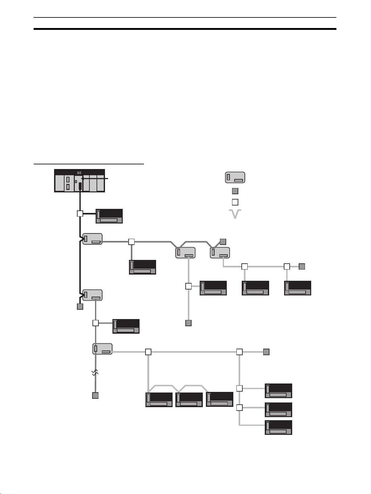
1-1-2 Overall System Configuration and Elements
A CompoNet Network is a remote I/O system that consists of the following
elements.
System Configuration Example
Trunk line
Terminating
Resistor
Sub-trunk
line
CompoNet Master Unit
Branch
line
Repeater Unit
Repeater
Unit
Branch
line
Repeater
Unit
Slave Unit
Sub-trunk line
Branch line
Slave Unit
: Repeater Unit
: Terminating Resistor
: T-branch
: Multidrop
Terminating
Resistor
Repeater Unit
Repeater
Unit
Sub-trunk
line
Terminating
Resistor
Sub-trunk line
Branch line Branch line
Sub-trunk line
Branch line Branch line
Terminating
Resistor
Terminating
Resistor
Sub-branch
lines
Terminating
Resistor
Multidrop connection on branch line
2
Page 24

CompoNet Networks Section 1-1
Communications Cables CompoNet Networks use Round Cable I, Round Cable II, Flat Cable I (DCA4-
4F10 Standard Flat Cable), and Flat Cable II (DCA5-4F10 Sheathed Flat
Cable) for Communications Cables.
Master Unit The Master Unit manages the CompoNet Network and transfers I/O data
between the PLC and the Slave Units.
There is only one Master Unit per network. The Master Unit must be connected to the end of the trunk line.
Slave Units Some Slave Units receive output data from the Master Unit across the Com-
poNet Network and output it. Other Slave Units send data that has been input
across the network to the Master Unit. There are two types of Slave Unit
according to the I/O capacity of the Slave Unit.
• Word Slave Units: A Word Slave Unit is allocated 16 bits (i.e., 16 I/O
points) in the I/O memory of the CPU Unit.
• Bit Slave Units: A Bit Slave Unit is allocated 2 bits (i.e., 2 I/O points) in the
I/O memory of the CPU Unit.
Repeater Unit Using Repeater Units enables expanding network connections as follows:
• Extending the Communications Cable
• Increasing the number of nodes (Units)
• Creating long-distance T-branches from the trunk line and sub-trunk lines
(See note.)
• Converting between different types of cable (round cable I, round cable II,
Flat Cable I, and Flat Cable II)
A sub-trunk line downstream from a Repeater Unit can be connected with the
same communications specifications (i.e., distances and number of Slave
Units) as the trunk line.
Up to 64 Repeater Units can be connected per network (i.e., per Master Unit).
When Repeater Units are connected in series from the Master Unit, up to two
layers can be created.
Note The physical layer is not connected across a Repeater Unit. The
connection is thus different from a branch connection, which
branches the same physical layer.
Terminating Resistors With a CompoNet Network, the Master Unit is located at one end of the trunk
line and a Terminating Resistor is connected to the other end of the trunk line.
If Repeater Units are used, each Repeater Unit is treated like a Master Unit,
i.e., Terminating Resistor is connected to the most remote end of the subtrunk line downstream from the Repeater Unit.
Note A Terminating Resistor reduces signal bouncing to stabilize com-
munications and must always be connected to the most remote end
of the network lines below the Master Unit and each Repeater Unit.
Always connect a Terminating Resistor to ensure the quality of the
transmission path.
Trunk Lines and Branch
Lines
The trunk lines and branch lines in a CompoNet Network are defined as follows:
• Trunk line: The transmission path between the Master Unit and the Terminating Resistor.
• Sub-trunk line: The transmission path between the Repeater Unit and the
Terminating Resistor (when a Repeater Unit is used)
• Branch line: The transmission path created using a T-branch from the
trunk line or sub-trunk line.
3
Page 25
CompoNet Networks Section 1-1
• Sub-branch line: The transmission path created using a T-branch from a
branch line. (T-branching is not possible from sub-branch lines.)
Note Due to differences in functionality, the same type of cable must be
used between the trunk line and a branch line, a sub-trunk line and
a branch line, and a branch line and a sub-branch line. Different
types of cable can be used between the trunk line and a sub-trunk
line.
Branches There are two ways to create branch lines.
1) T-branch Connections
• T-branch connections using Flat Connectors (when Flat Cable I or Flat
Cable II is used)
• T-branch connections using commercially available relay terminals (when
round cable I or round cable II is used)
2) Multidrop Connections
• Multidrop connections using Flat Connectors and Multidrop Connectors
(when Flat Cable I or Flat Cable II is used)
• Multidrop connections using Open Type Connectors (when round cable I
or round cable II is used)
Note Flat Connectors can also be used to extend the Communications
Cable.
Communications Power
Supply
This is the power supply for communications and internal operations for each
Unit.
A commercially available 24-VDC power supply is used for communications
and internal operations in each Unit.
One communications power supply can be connected for a trunk line or a subtrunk line. Communications power is supplied to the trunk line from the Master
Unit and to a sub-trunk line from the Repeater Unit.
One power supply cannot be used to supply communications power to more
than one line (i.e., to the trunk line and sub-trunk line or to two sub-trunk
lines).
I/O Power Supply A commercially available 24-VDC power supply is used to power the I/O oper-
ations of the external I/O device connected to a Unit. It is connected to the I/O
power supply terminal of the Unit.
1-1-3 System Configuration Patterns
Repeater Units connected
with multidrop connections
Master
Unit
Repeater
Unit
Sub-trunk
line
Slave Units connected
with multidrop
connections
Sub-trunk
line
Slave Units
Tr unk line
Repeater
Unit
Branch line
Slave Units
Slave Units
connected with Tbranch
connections
Repeater Units connected
with T-branch connections
Branch line Branch line Branch line
Repeater
Unit
Sub-trunk
line
Sub-trunk
line
Slave Units
Slave Units
connected with
multidrop
connections
Slave Units connected
with T-branch and then
multidrop connections
Repeater
Unit
Branch line
Slave Units
Slave Units
Slave Units connected
with T-branch
connections
Slave Units connected
with T-branch and
then T-branch
connections
Slave Units
Slave
Unit
Sub-trunk
line
Branch line
Sub-branch line
Repeater Unit
connected to
create second
segment layer
Slave Units
connected with
multidrop
connections
Ter minating
Resistor
Repeater Unit
Branch line
Branch line
Sub-trunk
line
Repeater Unit
Slave Units
: Slave Unit
: T-branch
: Multidrop
: Terminating Resistor
4
Page 26

CompoNet Networks Section 1-1
1-1-4 Features of CompoNet Networks
Programless
Communications
High-speed Multi-point
Processing
Repeater Units for Greater
Flexibility
With the use of only Round Cable I, Round Cable II, Flat Cable I and Flat
Cable II cables, cyclic data exchange or remote I/O communications can be
achieved between a Master Unit mounted in a PLC and multiple Slave Units.
Remote I/O communications for up to 2,560 I/O points can be achieved at
approximately 1,000 points per millisecond (at 4 Mbps, see note). This
enables configuring CompoNet Network systems to replace systems previously configured with Basic I/O Units.
Note Branch lines cannot be used at 4 Mbps. Slave Units with Cables
(i.e., Bit Slave Units) can thus not be used.
Easy Introduction
Remote I/O communications can be started merely by connecting the Master
Unit and Slave Units with communications cables, setting the switches on the
Master Unit, and turning ON the power to the Slave Units and PLC.
Repeater Units can be used in a network to enable the following network
expansions.
• Extending the cable length
• Increasing the number of nodes
• Branching from the trunk line
• Changing the type of cable
Repeater Units can be used to extend up to two segment layers (called subtrunk lines) from the trunk line. Up to 64 Repeater Units can be connected per
Master Unit and up to 32 Repeater Units can be connected to the trunk line.
Note Communications power is supplied to a sub-trunk line from the Re-
peater Unit.
Bit-level Distribution Slave Units with industry-standard e-CON connectors or clamping terminal
blocks can be used to distribute I/O at the bit level. This enables distributed
control in distributed devices, such as sensors and other devices located over
a wide area on conveyors or in warehouses.
Bit Slave Units are available in two types: IP20 and IP54.
Five Communications
Modes According to
Number of Nodes, I/O
Points, and Allocated
Memory
Data Exchange with
Message Communications
Easy Maintenance with
Complete System
Monitoring Functions
There are five communications modes that can be used according to number
of Slave Units, the number of I/O points, and the location of allocated memory.
Memory can be allocated to Slave Units in the Special I/O Unit portion of the
CIO Area or, if the CX-Integrator software settings are used, in any part of the
CIO, DM, Work, and Holding Areas.
This enables efficient application of memory according to the size of the system.
Message communications can be used from the CX-Integrator running on a
host computer or from the CPU Unit of the PLC to access Slave Units and
Repeater Units on the CompoNet Network. This enables easily improving network and system maintenance.
The CompoNet Network is constantly monitored to enable confirming system
safety by quickly isolating errors and checking communications status.
■ CX-Integrator
The CX-Integrator provides the following network functionality.
• Uploading the network configuration
• Editing and transferring software setting tables
5
Page 27

CompoNet Networks Section 1-1
• Editing and transferring registration tables
• Setting Input Data Zero Clear Mode for when communications error occur
• Setting I/O Communications Manual Startup Mode
• Monitoring Master Unit status
• Monitoring the Master Unit error history
• Monitoring Slave Unit network participation status
• Setting and transferring Slave Unit parameters
• Monitoring Slave Unit information
• Managing files
• Managing hardware (EDS files)
■ Smart Slave Unit Functions
The Slave Units provide Smart Functions that can record various added-value
information in addition to the ON/OFF signals (I/O data). This enables preventive system maintenance (including operation time monitoring and contact
operation counter monitoring) and aids in faster system introduction (including
communications power voltage monitoring and I/O power status monitoring).
Settings are possible from either the CX-Integrator or through message communications.
■ Master Unit Detection of Network Participation, Errors, and Status
When a Slave Unit joins the network, a bit corresponding to the node address
called a Participation Flag will turn ON. If a Slave Unit that has been participating in the network leaves the network, a bit corresponding to the node
address called an Error Flag will turn ON.
Network status, such as communications errors and redundant Slave Unit
node address, and Slave Unit diagnostic results are detected by the Master
Unit and display on the seven-segment display on the front panel and
reflected in the Status Flags.
■ Registration Tables
Tables of the Slave Unit that should be participating at each node (i.e., the
node address and corresponding Slave Unit model number) can be registered
from the CX-Integrator to verify the Slave Units actually participating in the
network and prevent unregistered Slave Units from participating in the network. A monitoring time for registered Slave Unit participation after power is
turned ON can also be set.
Remote I/O communications can be stopped until all registered Slave Units
are participating and remote I/O communications can be started as soon as
all registered Slave Units are participating (called Registered Slave Unit Participation Standby Mode).
■ Stopping Communications at Communications Errors
A DIP switch on the front of the Master Unit can be set to stop remote I/O
communications when a communications error has occurred in any of the
Slave Units.
■ I/O Communications Manual Startup Mode
I/O Communications Manual Startup Mode can be set from the CX-Integrator
so that remote I/O communications are not started when the power is turned
ON. Remote I/O communications will not start until the Remote I/O Communications Start Switch is turned ON in memory.
6
Page 28

CompoNet Network Specifications Section 1-2
■ Communications Error Input Data Zero Clear Mode
Input Data Zero Clear Mode can be set from the CX-Integrator for communications error. If a communications error occurs for a Slave Unit in this mode,
all input data for that Slave Unit will be cleared to zeros. This can be used to
suppress triggering operations when communications errors have occurred in
systems where ON input data signals are used as triggers for operation.
■ Communications Status on Master Unit Seven-segment Display
The seven-segment display on the front of the Master Unit can be used to
check communications status.
The baud rate is normally displayed, but if an error occurs, the error code is
displayed in hexadecimal and the error node address is displayed in decimal.
Automatic Baud Rate
Detection
The Slave Units will automatically detect and use the baud rate set on the DIP
switch on the Master Unit. Setting the baud rate is not necessary for any of the
Slave Units.
1-2 CompoNet Network Specifications
Item Specifications
Communications method CompoNet protocol
Types of communications Remote I/O communications (programless, constant sharing of data with Slave
Baud rate 4 Mbps (See note)., 3 Mbps, 1.5 Mbps, 93.75 kbps
Modulation Base-band
Coding Manchester code
Error control Manchester code rules, CRC
Communications media The following cables can be used.
Communications distance and wiring Refer to 1-2-1 Cable Types, Maximum Distances, and Number of Slave Units.
Connectable Master Units CompoNet Master Units
Connectable Slave Units CompoNet Slave Units
Maximum I/O capacity Word Slave Units: 1,024 inputs and 1,024 outputs (2,048 I/O points total)
Maximum number of nodes Word Slave Units: 64 input nodes and 64 output nodes
Bits allocated per node address Word Slave Units: 16 bits
Maximum number of nodes per trunk line
or sub-trunk line
Applicable node addresses Word Slave Units: IN0 to IN63 and OUT0 to OUT63
Units) and message communications (explicit message communications as
required with Slave Units and FINS message communications as required with
PLCs)
Note A baud rate of 4 Mbps is not supported for branch lines and thus cannot
be used for Slave Units with Cables (i.e., Bit Slave Units).
• Round Cable I (VCTF 2-conductor cable, JIS C3306)
• Round Cable II (VCTF 4-conductor cable, JIS C3306)
• Flat Cable I (DCA4-4F10 Standard Flat Cable)
• Flat Cable II (DCA5-4F10 Sheathed Flat Cable)
Note Round Cable I, Round Cable II, Flat Cable I, and Flat Cable II cables are
all treated as different types of cables. When two or more type of cables
are used in a single network, a Repeater Unit must be used to separate
any two different types of cables between the trunk line and a sub-trunk
line.
Bit Slave Units: 256 inputs and 256 outputs (512 I/O points total)
Bit Slave Units: 128 input nodes and 128 output nodes
Bit Slave Units: 2 bits
32 nodes including Repeater Units
Bit Slave Units: BIT IN0 to BIT IN127 and BIT OUT0 to OUT127
Repeater Units: 0 to 63
7
Page 29

CompoNet Network Specifications Section 1-2
Item Specifications
Repeater Unit application conditions Up to 64 Repeater Units can be connected per network (i.e., per Master Unit).
Signal lines Two lines: BDH (communications data high) and BDL (communications data
Power lines Two lines: BS+ and BS- (power for communications and internal Slave Unit cir-
Communications power supply voltage 24 VDC ±10%
Connection forms Round Cable II, Flat Cable I, or Flat Cable II cables at a baud rate of 93.75
Remote I/O communications Automatic startup when power is turned ON (see note) or manual startup using
I/O Communications Manual Startup
Mode
Communications Error Communications
Stop Mode
Communications Error Input Data Zero
Clear Mode
Duplicated Slave Unit address check If the same address is set for two different Slave Units or the same memory is
Registration Tables The Slave Units that can participate for each node address are registered in a
Up to 32 Repeater Units can be connected per trunk line or per sub-trunk line.
When Repeater Units are connected in series from the Master Unit, up to two
extra segment layers can be created (i.e., up to 2 Repeater Units are allowed
between a Slave Unit and the Master Unit).
low)
cuits)
• Power is supplied from the Master Unit and Repeater Units.
kbps: No restrictions
Other cables or other baud rates: Trunk line and branch lines
Connections for Slave Units and Repeater Units: T-branch or multidrop connections
the Remote I/O Communications Start Switch in I/O Communications Manual
Start Mode
Note When power is turned ON to the PLC and the Slave Unit communica-
tions power is turned ON. Communications are not started in the following cases:
• In Registered Slave Unit Participation Standby Mode, communications is not
started until all registered Slave Units are participating in the network.
• In Communications Error Communications Stop Mode, communications stop
when a communications error occurs.
I/O Communications Manual Startup Mode can be set from the CX-Integrator
so that remote I/O communications are not started when the power is turned
ON. Remote I/O communications will not start until the Remote I/O Communications Start Switch is turned ON in memory.
All remote I/O communications are stopped if a communications error occurs in
any Slave Unit.
Note Communications will not stop for verification errors for registration tables
or duplicated address settings.
All input data will be cleared to zeros in any Slave Unit in which a communications error occurs.
allocated to two different nodes, the Slave Unit that joins communications last
will cause a duplicated address error and will leave the network. The Duplicated Address Error Flag will turn ON.
Note This error will also occur if a Slave Unit leaves the network and then a
different type of Slave Unit joins the network.
table so that only the registered Slave Units can participate. If a different Slave
Unit attempts to join the network, the Registration Table Verification Error Flag
will turn ON. The Registration Table is generated automatically or manually
edited from the CX-Integrator.
8
Page 30
CompoNet Network Specifications Section 1-2
g
Item Specifications
Slave Unit
status
Without Registration Table Participation Flag and Communications Error Flag for each Slave Unit
• Participation Flag: Turns ON and remains ON if the Slave Unit joins the network even one time after system power is turned ON.
• Communications Error Flag: Turns ON if the Slave Unit cannot communicate
with the Master Unit for any reason after the Slave Unit has joined the network
(i.e., if the Participation Flag is ON). (Turns OFF when the error is removed.)
Duplicated Address Error Flags and Alarm Flags
With Registration Table • Participation Flags and Communications Error Flags for each node address
for all Slave Units registered in the Registration Table
• Registration Table Verification Error Flags
• All Registered Slave Units Participating Flag
Note The Registered Slave Unit Participation Monitoring Time can be set (ver-
ification error check timing).
Registered Slave Unit Participation Standby Mode can be set. (Remote
I/O communications will not start until all registered Slave Units are participating.)
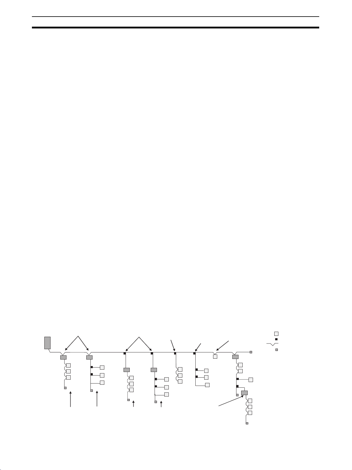
1-2-1 Cable Types, Maximum Distances, and Number of Slave Units
This section provides specifications on the maximum cable length and the
maximum number of connectable Slave Units for each type of cable. The
cables and Units must be used within the specifications.
: Slave Unit
: T-branch
: Multi-drop
Master Unit
Trunk line length
Branch line length
: Terminating Resistor
Sub-trunk
line length
Repeater
Unit
Subtrunk
line
length
Slave Units
Sub-trunk
line len
th
Trunk line
Repeater Unit
Branch line
Subtrunk
line
length
Branch line
Repeater
Unit
Sub-trunk
line length
Branch
line
Repeater
Unit
Branch
lines
Branch
line
Branch
line
Sub-branch
line
Sub-branch
line length
Slave
Unit
Sub-trunk
line length
Sub-trunk
line length
Terminating Resistor
Repeater Unit
Branch
line length
Branch
lines
Repeater Unit
Slave Units
■ Baud Rate of 4 Mbps (No branching allowed. See note.)
Item Round Cable I or II Flat Cable I or II
Length per trunk line or sub-trunk line (maximum
30 m (90 m) 30 m (90 m)
length with two Repeater Units)
Branch line length Lines cannot be branched from the trunk line. (Only multidrop con-
Total branch line length
nections are possible from the trunk line or subtrunk lines.)
Restrictions on branch line locations
Number of Slave Units (including Repeater Units)
32 32
per trunk line or sub-trunk line
Note Bit Slave Units come with Flat Cables and cannot be connected. The network
must consist of only Word Slave Units (use DCN4-MD4 Multidrop Connectors
for the Flat Cable I or Flat Cable II cables) and multidrop connections must be
used.
9
Page 31

CompoNet Network Specifications Section 1-2
■ Baud Rate of 3 Mbps
Item Round Cable I or II Flat Cable I or II
Length per trunk line or sub-trunk line (maximum
length with two Repeater Units)
Branch line length 0.5 m 0.5 m
Total branch line length 8 m 8 m
Restrictions on branch line locations 3 branches / m 3 branches / m
Number of Units per branch (See note.) 1 1
Maximum sub-branch line length Not supported Not supported
Total sub-branch line length Not supported Not supported
Number of Slave Units (including Repeater Units)
per trunk line or sub-trunk line
Note The maximum number of nodes per branch is the maximum number of Slave
Units or Repeater Units that can be connected to one branch line using multidrop or T-branch connections.
■ Baud Rate of 1.5 Mbps
Item Round Cable I Round Cable II, Flat
Length per trunk line or sub-trunk line (maximum
length with two Repeater Units)
Branch line length Not supported (See
Total branch line length Not supported (See
Restrictions on branch line locations --- 3 branches / m 3 branches / m
Number of Units per branch (See note 1.) 3 3
Maximum sub-branch line length Not supported 0.1 m (See note 3.)
Total sub-branch line length Not supported 2 m (See note 3.)
Number of Slave Units (including Repeater Units)
per trunk line or sub-trunk line
30 m (90 m) 30 m (90 m)
32 32
Without branch
lines
100 m (300 m) 30 m (90 m) 30 m (90 m)
note 2.)
note 2.)
32 32 32
With branch lines
2.5 m 2.5 m
25 m 25 m
Cable I, or Flat
Cable II
10
Note (1) This is the maximum number of Slave Units and Repeater Units com-
bined that can be connected to a branch line by using multidrop connections and/or T-branching. T-branching creates a sub-branch.
(2) The trunk line does not support branching. The trunk line and sub-trunk
lines support only multidrop connections.
(3) Branch lines support branching to sub-branch lines.
Page 32

CompoNet Network Specifications Section 1-2
■ Baud Rate of 93.75 kbps
Item Round Cable I or II Flat Cable I or II
Length per trunk line or sub-trunk line(maximum
length with two Repeater Units)
Branch line length 6 m
Total branch line length 120 m
Restrictions on branch line locations 3 branches / m
Number of Units per branch (See note.) 1
Maximum sub-branch line length ---
Total sub-branch line length ---
Number of Slave Units (including Repeater Units)
per trunk line or sub-trunk line
500 m (1500 m) Unrestricted wiring is enabled
for a total length of 200 m.
32 32
Note This is the maximum number of Slave Units and Repeater Units combined
that can be connected to a branch line by using multidrop connections and/or
T-branching. T-branching creates a sub-branch.
1-2-2 Branch Line Support for Cable Types and Baud Rates
Support for branch lines from the trunk line or sub-trunk lines and support for
sub-branch lines from branch lines is listed in the following tables.
■ Baud Rate of 4 Mbps (No Branch Lines)
Cable Branch lines Sub-branch lines
Round Cable I Not supported Not supported
Round Cable II, Flat Cable I, or Flat
Cable II
Not supported Not supported
Note A baud rate of 4 Mbit/s is not supported for branch lines and thus
cannot be used for Slave Units with Cables (i.e., Bit Slave Units).
The network must consist of only Word Slave Units and DCN4MD4 Multidrop Connectors must be used for Flat Cable I and Flat
Cable II cables.
■ Baud Rate of 3 Mbps
Cable Branch lines Sub-branch lines
Round Cable I Supported Not supported
Round Cable II, Flat Cable I, or Flat
Cable II
■ Baud Rate of 1.5 Mbps
Cable Branch lines Sub-branch lines
Round Cable I 100 m max. Not supported Not supported
30 m max. Supported
Round Cable II, Flat Cable I, or Flat
Cable II
Supported Not supported
Supported Supported
■ Baud Rate of 93.75 kbps
Cable Branch lines Sub-branch lines
Round Cable I Supported Not supported
Round Cable II, Flat Cable I, or
Flat Cable II
Supported (no restrictions)
11
Page 33

CompoNet Network Specifications Section 1-2
1-2-3 Allocating Slave Units in the CPU Unit Memory Area by
Communications Mode Number
Slave Unit I/O information and status information is allocated in the Special
I/O Unit memory area or a user-specified area of the CPU Unit to which the
Master Unit is mounted.
The area is determined by the unit number of the Master Unit as a Special I/O
Unit and by the communications mode number. The user specifies the communications mode number using the CX-Integrator. The bits used by Slave
Units are determined by the node address for each Slave Unit.
The relationship between communications mode numbers, the number of
connected nodes, and the number of points that can be controlled is
described next.
Number of Connected Nodes and Control Points Per Master Unit
Use the rotary switch on the front of the Master Unit to select the communications mode number.
Word: 64 nodes
Word: 32 nodes
1
Word: 16 nodes
0
9
Reserved
Software Setting Mode
Commu-
nications
mode
number
0 Mode 0 Word Slave Units: IN0 to
1 Mode 1 Word Slave Units: IN0 to
2 Mode 2 Word Slave Units: IN0 to
3 Mode 3 Word Slave Units: IN0 to
4 Reserved --- --- --- ---
5 Reserved --- --- --- ---
6 Reserved --- --- --- ---
7 Reserved --- --- --- ---
8 Software
9 Reserved --- --- --- ---
Mode
name
Setting
Mode
Connectable node
addresses
IN7 and OUT0 to OUT7
IN15 and OUT0 to OUT15
IN31 and OUT0 to OUT31
IN15 and OUT0 to OUT15
Bit Slave Units: IN0 to
IN63 and OUT0 to OUT63
Can be set within the following ranges:
Word Slave Units: IN0 to
IN63 and OUT0 to OUT63
Bit Slave Units: IN0 to
IN127 and OUT0 to
OUT127
128 inputs and 128 outputs (Word Slave Units)
256 inputs and 256 outputs (Word Slave Units)
512 inputs and 512 outputs (Word Slave Units)
256 inputs and 256 outputs (Word Slave Units)
128 inputs and 128 outputs (Word Slave Units)
Can be set within the following ranges:
Word Slave Units: 1,024
inputs and 1,024 outputs
Bit Slave Units: 256 inputs
and 256 outputs
Word: 32 nodes + Bit: 128 nodes
2 3
MODE
4
Reserved
5
6
7 8
Reserved
Control points Memory area
Special I/O Unit Area
(First word depends on
unit number of Master
Unit.)
Can be allocated anywhere in the CIO, DM,
WR, or HR Area.
Note Status and
parameters are
allocated in the
Special I/O Unit
Area.
Number of
unit numbers
used by each
Master Unit
2
4
8
8
1
12
Page 34

Devices in a CompoNet Network Section 1-3
9
8
7
6
5
4
3
2
1
0
9
8
7
6
5
4
3
2
1
0
9
8
7
6
5
4
3
2
1
0
Note (1) In a CompoNet Network, Word Slave Units have 16 bits per node ad-
dress. Bit Slave Units have two bits allocated per node address.
(2) Do not use the reserved communications mode numbers (4 to 7 and 9).
A communications mode setting error (H4 at the 7-segment LED indicator) will occur if any of these mode numbers is set.
1-3 Devices in a CompoNet Network
1-3-1 Master Units
CompoNet Master Units
Communications Cables
(Yes: Can be used. No: Cannot be
used.)
Round
Cable I
Ye s (S e e
note 1.)
Round
Cable II
Yes (See
note 1.)
Flat
Cable I
Ye s (S e e
note 2.)
Flat
Cable II
Ye s ( S ee
note 3.)
Name Model
CS-series
Master Unit
C
R
M
2
1
MS
+
1
0
0
NS
S
D
R
D
M
A
C
H
N
o
.
1
X
1
0
0
X
1
0
M
O
D
E
ON
1234
1
D
R
0
2
D
R
1
3
E
S
T
P
4
REGS
N
E
T
W
O
R
K
P
O
W
E
R
S
U
P
P
L
Y
B
S
+
B
S
-
D
C
2
4
V
I
N
P
U
T
B
S
+
B
D
H
B
D
L
B
-
S
CS1WCRM21
Unit
classifica-
tion
CS-series
Special I/O
Unit
Maximum number per CPU Unit
Communications
mode No.
8 (1 unit number
80
used)
0 (2 unit num-
48
bers used)
1 (4 unit num-
24
bers used)
2 or 3 (8 unit
12
numbers used)
CJ-series
Master Unit
C
R
M
2
1
+
1
M
0
0
S
N
S
SD
SW
RD
1234
O
N
MACH
3
No.
2
4
1
5
0
6
1
7
2
3
8
9
4
1
X
1
0
N
E
T
W
3
O
2
4
R
K
P
S
1
5
0
6
7
8
9
0
X
1
0
MODE
B
3
S
+
2
4
1
5
0
6
7
B
S
8
-
9
D
C
2
4
V
I
N
P
U
T
B
S
+
B
D
H
D
B
L
B
S
-
CJ1WCRM21
CJ-series
Special
Communications
mode No.
8 (1 unit number
CJ1-H/
CJ1 CPU
Units
CJ1M
CPU
Units
40 20
Ye s (S e e
note 1.)
Yes (See
note 1.)
Ye s (S e e
note 2.)
Ye s ( S ee
note 3.)
used)
0 (2 unit num-
40 20
bers used)
1 (4 unit num-
24 20
bers used)
2 or 3 (8 unit
12 12
numbers used)
Note (1) A DCN4-TB4 Open Type Connector is required to connect a Round Cable
I or Round Cable II cable to the Unit.
(2) A DCN4-TR4 Flat Connector Socket is required to connect a Flat Cable I
cable.
(3) A DCN5-TR4 Flat Connector Socket is required to connect a Flat Cable
II cable.
13
Page 35

Devices in a CompoNet Network Section 1-3
1-3-2 Peripheral Devices
Communications Cables
The following table shows the Communications Cables that can be used in a
CompoNet Network.
Name Model Specifications Remarks
Round Cable I --- JIS C 3306
Round Cable II
Flat Cable I DCA4-4F10 Standard 4-conductor flat cable (UL2555)
Nominal cross-sectional area: 0.75 mm
Finished conductor diameter: 2.3 mm
Length: 100 m
Conductor diameters:
0.75 mm2 × 2, 0.5 mm2 × 2
Cannot be used with Bit Slave
Units.
2
,
Approximately 50 cm of cable
comes connected to IP20 Bit
Slave Units.
Flat Cable II DCA5-4F10 Sheathed 4-conductor flat cable
Length: 100 m
Conductor diameters:
0.75 mm
2
× 2, 0.5 mm2 × 2
Approximately 50 cm of cable
comes connected to IP54 Bit
Slave Units.
Flat Connectors In a CompoNet Network, the connectors described below can be connected
to the Communications Cable to enable extending the cable length, branching
cables, and wiring to Slave Units.
Flat Connector Socket
■ Flat Cable I
Communications Cables
(Yes: Can be used.
Name Model Appearance Application
Flat Connector
Socket
DCN4-TR4 Use this Connector in a set with
a DCN4-BR4 Flat Connector
Plug for the following applications.
• Extending the trunk line or a
sub-trunk line
No: Cannot be used.)
Round
Cable I
Round
Cable II
Flat
Cable I
Flat
Cable II
14
No
• T-branching from the trunk line
or a sub-trunk line
• T-branching a sub-branch line
from a branch line
Ye s
(See
note.)
Ye s N o
Note The only case when the Socket is used with a Round Cable II is to connect
the Cable to a Terminating Resistor.
Page 36

Devices in a CompoNet Network Section 1-3
■ Flat Cable II
Communications Cables
(Yes: Can be used.
Name Model Appearance Application
Flat Connector
Socket
DCN5-TR4 Use this Connector in a set with
a DCN5-BR4 Flat Connector
Plug for the following applications.
• Extending the trunk line or a
sub-trunk line
• T-branching from the trunk line
or a sub-trunk line
• T-branching a sub-branch line
from a branch line
Note Use the Connector to
connect IP54 Bit Slave
Units.
Flat Connector Plug
■ Flat Cable I
Name Model Appearance Application
Flat Connector
Plug
DCN4-BR4 a. Use the Connector in a set
with a DCN4-TR4 Flat Connector Socket for the following applications.
• Extending the trunk line or a
sub-trunk line
• T-branching from the trunk line
or a sub-trunk line
• T-branching a sub-branch line
from a branch line
b. Use this Connector indepen-
dently for the following applications.
• Connecting Communications
Cable to a Master Unit, Word
Slave Unit, or Repeater Unit
• Connecting Communications
Cable to a Multi-wiring Connector
No: Cannot be used.)
Round
Cable I
No No No Yes
Round
Cable I
No No Yes No
Round
Cable II
Communications Cables
(Yes: Can be used.
No: Cannot be used.)
Round
Cable II
Flat
Cable I
Flat
Cable I
Cable II
Flat
Cable II
Flat
Note Although this product is called a Flat Connector Plug, it can be
used as a connector to connect a Master Unit, Slave Unit, or Repeater Unit.
15
Page 37

Devices in a CompoNet Network Section 1-3
■ Flat Cable II
Communications Cables
(Yes: Can be used.
Name Model Appearance Application
Flat Connector
Plug
DCN5-BR4 a. Use this Connector in a set
with a DCN5-TR4 Flat Connector Socket for the following
applications.
• Extending the trunk line or a
sub-trunk line
• T-branching from the trunk line
or a sub-trunk line
• T-branching a sub-branch line
from a branch line
b. Use this Connector indepen-
dently for the following applications.
• Connecting Communications
Cable to a Master Unit, Word
Slave Unit, or Repeater Unit
• Connecting Communications
Cable to connectors for wiring
Note Use for connecting IP54
Bit Slave Units.
No: Cannot be used.)
Round
Cable I
Round
Cable II
No No No Yes
Flat
Cable I
Flat
Cable II
Note Although this product is called a Flat Connector Plug, it can be
used as a connector to connect a Master Unit, Slave Unit, or Repeater Unit.
Multi-wiring Connector
Name Model Appearance Application
Multi-wiring Connector
DCN4-MD4 This Connector connects two
Flat Connector Plugs to two
ports.
Use Multi-wiring Connectors for
multi-drop wiring of Master
Units, Slave Units, or Repeater
Units to trunk lines, sub-trunk
lines, or branch lines.
Note When the baud rate is 4
Mbps (mainly when Flat
Cable is used), use this
Connector to connect to
Word Slave Units only.
Communications Cables
(Yes: Can be used.
No: Cannot be used.)
Round
Cable I
Round
Cable II
No No Yes No
Flat
Cable I
Flat
Cable II
16
Page 38

Devices in a CompoNet Network Section 1-3
Special Tools
Communications Cables
(Yes: Can be used.
Name Model Appearance Application
Special Tool (Pliers)
DWT-A01 A pressure welding tool for
DCN4-TR4 Flat Connector Socket and a DCN4BR4 Flat Connector Plug.
No: Cannot be used.)
Round
Cable I
No
Round
Cable II
Ye s
(See
note.)
Flat
Cable I
Ye s N o
Flat
Cable II
Special Tool (Pliers)
DWT-A02 A pressure welding tool for
DCN5-TR4 Flat Connector Socket and a DCN5BR4 Flat Connector Plug.
Note The only case when the Special Tool is used with a Round Cable II cable is to
connect the Cable to a Terminating Resistor.
Open Type Connector
Name Model Appearance Application
Open Type Connector
DCN4-TB4 Converts the communications
connector on a Unit to a screw
terminal block to enable connecting a Round Cable I or II
cable to a Slave Unit or
Repeater Unit.
Terminating Resistors
Name Model Appearance Application
Terminating
Resistor
DCN4-TM4 Connector-type Terminating
Resistor for a Round Cable II
or Flat Cable I cable. Connect
this Terminating Resistor to a
Flat Connector Socket (DCN4TR4) on the end of the trunk or
sub-trunk line.
DCN5-TM4 Connector-type Terminating
Resistor for a Flat Cable II
cable. Connect this Terminating Resistor to a Flat Connector Socket (DCN5-TR4) on the
end of the trunk or sub-trunk
line.
DRS1-T Terminal block-type Terminat-
ing Resistor for a Round Cable
I cable. Connect this Terminating Resistor to the end of the
trunk or sub-trunk line.
No No No Yes
Communications Cables
(Yes: Can be used.
No: Cannot be used.)
Round
Cable I
Yes Yes No No
Round
Cable I
Ye s Νο No No
Round
Cable II
Communications Cables
(Yes: Can be used.
No: Cannot be used.)
Round
Cable II
No Yes Yes No
No No No Yes
Flat
Cable I
Flat
Cable I
Flat
Cable II
Flat
Cable II
17
Page 39

Devices in a CompoNet Network Section 1-3
1-3-3 Selecting Peripheral Devices Used According to Connection
Configuration
Flat Cable I, Round Cable I, or Round Cable II
Connection configuration Peripheral Devices used
Connecting the Master Unit Connecting the trunk line to the Master
Unit
Connecting Slave Units or
Repeater Units
Branching T-branching T-branching from a trunk or sub-trunk
Multi-drop
branching
Extending the line length Extending the trunk line or a sub-trunk
Terminating Resistor Installing Terminating Resistors on
Connecting branch lines or sub-branch
lines to Slave Units or Repeater Units
line
T-branching a sub-branch line from a
branch line
Multi-drop branching of the trunk line or
a sub-trunk line
Multi-drop branching of a branch line or
sub-branch line
line
Extending a branch line
trunk lines or sub-trunk lines
Flat Connector Plug (DCN4-BR4) only, or Open
Type Connector (to connect Units to the Cable)
(DCN4-TB4)
Flat Connector Plug (DCN4-BR4) only, or Open
Type Connector (to connect Units to the Cable)
(DCN4-TB4)
Flat Connector Socket (DCN4-TR4) with Flat Connector Plug (DCN4-BR4) as a set, or commercially
available terminal blocks
Open Type Connector (to connect Units to the
Cable) (DCN4-TB4), or Multidrop Connector
(DCN4-MD4)
Flat Connector Socket (DCN4-TR4) with Flat Connector Plug (DCN4-BR4) as a set
Terminating Resistor (DCN4-TM4 or DRS1-T)
Flat Cable II
Connection configuration Peripheral Devices used
Connecting the Master Unit Connecting the trunk line to the Master
Unit
Connecting Slave Units or
Repeater Units
Branching T-branching T-branching from a trunk or sub-trunk
Extending lines Extending the trunk line or a sub-trunk
Terminating Resistor Installing Terminating Resistors on
Connecting branch lines or sub-branch
lines to Slave Units or Repeater Units
line
T-branching a sub-branch line from a
branch line
line
Extending a branch line
trunk lines or sub-trunk lines
Flat Connector Plug (DCN5-BR4) only, or Open
Type Connector (to connect Units to the Cable)
(DCN4-TB4)
Flat Connector Plug (DCN5-BR4) only, or Open
Type Connector (to connect Units to the Cable)
(DCN4-TB4)
Flat Connector Socket (DCN5-TR4) with Flat Connector Plug (DCN5-BR4) as a set
Flat Connector Socket (DCN5-TR4) with Flat Connector Plug (DCN5-BR4) as a set
Terminating Resistor (DCN5-TM4)
18
Page 40

Overview of Design Flow Section 1-4
1-4 Overview of Design Flow
Perform the following steps to design the system.
1. Determine the number of I/O points. ...Refer to 1-2 CompoNet Net-
Determine the number of I/O points in the entire system.
▼
2. Match up the I/O points with specific Slave Units.
Determine the specific Slave Unit for each input and output.
▼
3. Determine the number of nodes.
Determine how many nodes are to be connected.
▼
4. Determine the layout. ...Refer to SECTION 3 Wiring
• Determine the wiring form (trunk line-branch lines or unrestricted
branching).
• Determine the wiring distances.
• Determine the method for providing communications and I/O power
supplies to the Slave Units (with minimal wiring).
• Determine the type of cable to be used.
▼
5. Temporarily determine the communications mode number and the baud rate.
Note Branching is not possible at a baud rate of 4 Mbps, so Bit Slave Units with Flat
Cable cannot be used.
▼
6. Determine the communications cycle.
The communications cycle is determined from the communications
mode number and the baud rate.
(With communications mode 8, it also depends on the type and number
of Slave Units.)
Determine whether the required I/O response time can be achieved at
that baud rate.
▼
7. Consider using more than one Master Unit.
If the desired distance and communications cycle cannot both be
achieved even after rechecking the communications mode number, the
baud rate, and the use of Repeater Units, then use more than one Master Unit.
work Specifications and 1-3
Devices in a CompoNet Network.
Configurations.
...Refer to 5-3 Remote I/O
Communications Performance.
19
Page 41

Overview of Operating Procedure Section 1-5
1-5 Overview of Operating Procedure
Follow the steps below to install and use a CompoNet Network.
1. Install and wire the system. ... SECTION 4 Installation and
Wire the network, the communications power supply, and the I/O power
supply.
▼
2. Select the communications mode number on the front of the Master Unit. ...SECTION 2 Master Units
Set the communications mode number to 0, 1, 2, 3, or 8.
▼
3. Make the following settings on the DIP switch on the front of the Master Unit.
SW1 (DR0) and SW2 (DR1): Set the baud rate.
SW3 (ESTP): Set whether communications are to stop when an error
occurs.
SW4 (REGS): Enable or disable the Registration Table.
▼
4. Set the unit number on the front of the Master Unit.
Set a number from 0 to 95.
▼
5. Set the Slave Unit node addresses.
Set a node addresses from 0 to 63 for Word Slave Units and from 0 to
127 for Bit Slave Units.
▼
6. Connect the computer running the CX-Integrator to the PLC where the Master
Unit is mounted.
▼
7. Turn ON the power to the PLC.
▼
8. Using the CX-Integrator, edit and download the Master Unit device parameters.
1. Connect online to the PLC where the Master Unit is mounted.
2. In the Online Connection Information Window, right-click the Master
Unit under the connected PLC, and then select Connect.
3. Right-click the Master Unit under the connected PLC, and select
Transfer [Network to Computer].
4. Double-click the Master Unit in the Network Configuration Window,
and then edit and download the device parameters.
▼
9. Turn OFF the power to the PLC.
▼
10.Remote I/O communications will start when all registered Slave Units are participating.
▼
11.Using the CX-Integrator, monitor the participation status of the Slave Units.
1. While online, upload the network configuration.
2. Right-click the Master Unit in the Network Configuration Window and
select Monitor to monitor the participation status on the Status/Unit
Status Tab Page.
Wiring
...CX-Integrator Operation
Manual
20
Page 42

Design and Operating Procedure Examples Section 1-6
1-6 Design and Operating Procedure Examples
1-6-1 Design
I/O Capacity Establish the I/O correspondences for each Slave Unit. Determine how many
Word and Bit Slave Units are to be connected, and calculate the current consumption for the communications power supply.
■ Units Used
I/O capacity Slave Unit type Model (specifications) Number of Units Current consumption (See note 1.)
16 inputs Word Slave Units CRT1-ID16 (16 DC inputs,
16 inputs and
8 outputs
16 outputs CRT1-OD16 (16 transistor
2 inputs × 2 Bit Slave Units CRT1B-ID02S (2 DC inputs,
2 outputs CRT1B-OD02S (2 transistor
NPN)
CRT1-ID16 (16 DC inputs,
NPN) + XWT-OD08 (8 transistor outputs, NPN)
outputs, NPN)
sensor connector type,
NPN)
outputs, sensor connector
type, NPN)
1 85 mA
1 of each 85 mA + 5 mA = 90 mA
1 85 mA
2 80 mA + I/O current consumption 76
mA (Sensor example: 35 mA × 2 +
input current 3 mA × 2) (See note 2.)
Note The total for two Units is 160
mA + 152 mA.
1 75 mA + I/O current consumption 160
mA (actuator)
Example: 80 mA × 2 (See note 2.)
Total 495 mA + 312 mA for I/O = 807 mA
Note (1) Refer to the CRT1-series CompoNet Slave Units and Repeater Unit Op-
eration Manual (Cat. No. W456) for the current consumption of the Slave
Units.
(2) When Bit Slave Units are used, the current consumption of the Bit Slave
Units and the external I/O, such as sensors and actuators, is supplied
from the communications power supply that is connected to the Master
Unit through the Flat Cable. Therefore, the current consumption of the following external I/O must be added to the total power consumption.
Sensor current consumption
Word Slave Units
× 3 nodes, Bit Slave Units × 3 nodes
× 2, actuator current consumption × 2
At the same time, provide a 24-VDC power supply with an output current
of at least 0.9 A for the communications power supply.
■ Required Peripheral Devices
Specifications Model Quantity Remarks
Flat Connector Socket DCN4-TR4 7 Order in units of ten.
Flat Connector Plug DCN4-BR4 10 Order in units of ten.
Terminating Resistor DCN4-TM4 1 Order in units of ten.
Flat Cable I DCA4-4F10 1 Order in increments of 100 m.
Special Tool (Pliers) DWT-A01 1 ---
21
Page 43

Design and Operating Procedure Examples Section 1-6
System Configuration
Computer (CX-Integrator)
CJ-series CPU Unit
CJ-series Master Unit
CJ-series PLC
16 inputs
#0
CompoNet Flat Cable
16 inputs + 8 outputs
#1
Word Slaves
16 outputs
#2
2 inputs
BIT#0
2 inputs
BIT#1
Bit Slaves
2 outputs
BIT#2
Layout • Wiring form: Branching from trunk line to branch lines, with no sub-branch
lines
• Wiring distance: 30 m or less, so any cable type or baud rate is acceptable.
• Communications Power Supply to Slave Units: Supplied to all collectively.
Cable type Round Cable I Round Cable II, Flat Cable I, or Flat
Baud rate 4 Mbps 3 Mbps 1.5 Mbps 93.75
Wiring
form
No branch lines All can be used.
With
branch
lines
Without
sub-branch
lines
(branch line
extension)
With subbranch lines
Maximum length for trunk
lines and sub-trunk lines
kbps
4 Mbps 3 Mbps 1.5
Not
supported.
Supported
(0.5 m).
Not
supported.
Supported
(2.5 m)
Supported
(6 m).
Not
supported.
Not supported. Not supported. Sup-
30 m 100 m 30 m 500 m 30 m 200 m (unre-
Supported
(0.5 m).
Cable II
Mbps
Supported
(2.5 m).
ported
(2.5 m).
93.75 kbps
Supported
(unrestricted
branching).
Supported
(unrestricted
branching).
stricted
branching)
22
■ Remarks
Wiring Form
• When there is no branching, any combination of cable types and baud
rates are supported.
• When there is a branch, Round Cable I, Round Cable II, Flat Cable I and
Flat Cable II cables cannot be used at a baud rate of 4 Mbps. This means
you cannot use a Bit Slave Unit with a pre-attached cable at 4 Mbps.
When a Round Cable I cable is used at a baud rate of 1.5 Mbps, the trunk
line and the sub-trunk line must be no longer than 30 m.
• When a branch line has a sub-branch line, Round Cable II, Flat Cable I, or
Flat Cable II cables must be used either at a baud rate of 1.5 Mbps or
93.75 kbps.
Page 44

Design and Operating Procedure Examples Section 1-6
Maximum Length for Trunk Lines and Sub-trunk Lines
• When the lines are 30 m or less: Any combination of cable types and
baud rates is supported.
• When a distance longer than 30 m is required:
• Round Cable I: The baud rate must be 1.5 Mbps, with no branching.
(The cable length can be up to 100 m.)
• Round Cable II, Flat Cable I, or Flat Cable II: The baud rate must be
93.75 bits/s. (The cable length can be up to 200 m when unrestricted
branching is used.)
23
Page 45

Design and Operating Procedure Examples Section 1-6
Types of Cables Flat Cable is used in this example, because IP20 Bit Slave Units are used and
the communications power supply is provided collectively through the communications cables.
Item
Application Wiring the Slave Units between the Master Unit and a Repeater Unit and
Applicable
Slave Units
Communications power supply Wired separately
Condition to use different types of
cables together
Master Unit position Only at the end of
Branch lines At 4 Mbps: Not
Branching from
branch lines
Multi-wiring
Word Slave Units Supported
Bit Slave
Units
Multidrop connections
on branch lines
Sub-branch lines Not supported At 93.75 kbps: Unrestricted wiring
IP20 Bit
Slave
Units
IP54 Bit
Slave
Units
Round Cable I Round Cable II Flat Cable I Flat Cable II
wiring the Slave Units downstream from a Repeater Unit
•To wire with
commercially
available cable.
• To supply communications
power separately.
• When Bit Slave
Units are not
used.
Not supported. (See note.)
Note Round Cables cannot be used
with Bit Slaves. Flat Cables
are pre-connected to all Bit
Slaves.
from the communications cable.
When a Repeater Unit is used, two different types of cables can be used
(two of Round Cable I, Round Cable II, Flat Cable I, and Flat Cable II): one
for the upstream port and the other for the downstream port.
In other cases, all cables on the trunk line, a sub-trunk line, a branch line, or
a sub-branch line must be the same type.
trunk line
supported
At other baud
rates: Supported
At 1.5 Mbps:
Supported (up to
3 connectors per
branch line)
• To wire with
commercially
available cable
• To supply the
communications power collectively via the
communications cable.
• When Bit Slave
Units are not
used.
Supplied via communications cable. (Power is supplied
from the Master Unit and Repeater Units.)
At baud rate of 93.75 kbps: Anywhere in the network
At other baud rates: Only at the end of trunk line
At 93.75 kbps: Unrestricted wiring
At 4 Mbps: Not supported
At other baud rates: Supported
At 93.75 kbps: Unrestricted wiring
At 1.5 Mbps: Supported (up to 3 con-
nectors per branch line)
At 1.5 Mbps: supported (up to 3 connectors per branch
line)
Cable type
• To use the communications
cable and the
communications power to
supply power to
all Slave Units.
• When an IP20
Bit Slave Unit is
used.
Supported Not supported
Not supported Supported
• To use the communications
cable and the
communications power to
supply power to
all Slave Units.
• When an IP54
Bit Slave Unit is
used.
• To use in an
environment
conforming to
IP54 (splashproof and dripproof.)
Not supported
24
Page 46

Design and Operating Procedure Examples Section 1-6
Communications distance
Item
4 Mbps Length of the trunk line or a sub-trunk line: 30 m max
3 Mbps Length of the trunk line or a sub-trunk line: 30 m max
1.5 Mbps Length of the
93.75 kbps Length of the
Round Cable I Round Cable II Flat Cable I Flat Cable II
trunk line or a
sub-trunk line:
100 m max. when
there is no
branching, 30 m
max. when there
is branching
trunk line or a
sub-trunk line:
500 m max
Unit Number Unit number 5 is used.
Communications Mode
Number and Baud Rate
• Communications mode number: 3 (Mode 3 is selected because Word
Slave Units and Bit Slave Units are used.) Memory can be allocated in the
Special I/O Unit portion of the CIO Area, so a CX-Integrator setting is not
required.
• Baud rate: 3 Mbps (Branch lines are used, but not sub-branch lines. Also,
this baud rate can be used with a maximum trunk line length of 30 m.)
Communications Cycle
Time
The communications cycle time is 2.5 ms, at a baud rate of 3 Mbps in communications mode 3. Base calculations on a communications cycle time of 2.5
ms. (For details on I/O response times, refer to 5-3 Remote I/O Communica-
tions Performance.)
Cable type
Length of the trunk line or a sub-trunk line: 30 m max
Total wiring length: 200 m max
Slave Unit type and maximum
number of nodes
Word Slave Units, max. 8 nodes
input and 8 nodes output
Word Slave Units, max. 16 nodes
input and 16 nodes output
Word Slave Units, max. 32 nodes
input and 32 nodes output
Word Slave Units, max. 16 nodes
input and 16 nodes output; Bit
Slave Units, max. 64 nodes input
and 64 nodes output
Word Slave Units, max. 64 nodes
input and 64 nodes output; Bit
Slave Units, max. 128 nodes
input and 128 nodes output
Baud rate
Communications
mode No.
0 0.9 ms 0.9 ms 1.5 ms 19.8 ms
1 1.0 ms 1.2 ms 2.3 ms 30.2 ms
2 1.3 ms 1.7 ms 4.0 ms 51.3 ms
3 2.0 ms 2.5 ms
8 0.79 ms +
Communications cycle time (with message communications)
4 Mbps 3 Mbps 1.5 Mbps 93.75 kbps
added time for
number of and
types of Slave
Units
Note When less than the maximum number of nodes is used, the communications
cycle time is progressively shortened as the communications mode number
becomes smaller and as the baud rate is increased.
Registration Tables Registration tables are used.
• Registered Slave Unit Participation Standby Mode
Communications Error
These are enabled.
Communications Stop
Mode
0.85 ms +
added time for
number of and
types of Slave
Units
5.9 ms 72.1 ms
1.94 ms +
added time for
number of and
types of Slave
Units
24.81 ms +
added time for
number of and
types of Slave
Units
25
Page 47

Design and Operating Procedure Examples Section 1-6
I/O Allocations
Special I/O
Unit Memory
Area
CIO 2000 +
(10 × unit
number 5)
Word address Bit 15 8 7 Bit 0
2050 [ OUT0 ] Not used.
2051 [ OUT1 ] XWT-OD08
Not used.
2052 [ OUT2] CRT1-OD16
2065 [ OUT15 ] Not used.
2066 [ IN0 ] CRT1-ID16
2067 [ IN1 ] CRT1-ID16
[ IN2 ] Not used.
2081 [ IN15 ] Not used.
2083
2089
2090
2097
[ BIT OUT7] [ BIT OUT6] [ BIT OUT5] [ BIT OUT4]
[ BIT OUT63] [ BIT OUT62] [ BIT OUT61] [ BIT OUT60] [ BIT OUT59] [ BIT OUT58] [ BIT OUT58] [ BIT OUT56]
[ BIT IN7] [BIT IN6] [ BIT IN5] [ BIT IN4] [ BIT IN3] [ BIT IN2]
[ BIT IN63] [ BIT IN62] [ BIT IN61] [ BIT IN60] [ BIT IN59] [ BIT IN58] [ BIT IN57] [ BIT IN56]
2098
2099
[ BIT OUT1]
[ BIT OUT0]
CRT1B-OD02SP
[BIT OUT1] [ BIT OUT0]
[ BIT IN0]
[ BIT IN1]
CRT1B-ID02S
CRT1B-ID02S
CRT1B-OD02SP
Status
Parameters
2100
2101
2104
2105
2119
OUT 1 (CIO 2051, bits 00 to 07) : XWT-OD08
OUT 2 (CIO 2052, bits 00 to 15) : CRT1-OD16
IN0 (CIO 2066, bits 00 to 15) : CRT1-ID16
IN1 (CIO 2067, bits 00 to 15) : CRT1-ID16
BIT OUT1 (CIO 2083, bits 02 and 03) : CRT1B-OD02S
BIT OUT2 (CIO 2090, bits 04 and 05) : CRT1B-MD04SLP
BIT IN0 (CIO 2090, bits 00 and 01): CRT1B-ID02S
BIT IN2 (CIO 2090, bits 02 and 03) : CRT1B-MD04SLP
CIO 2098, bit 08 F Ladder Operation Allowed Flag
OUT2 Participation Flag (CIO 2100, bit 02)
OUT2 Communications Error Flag (CIO 2100, bit 10)
IN0 Participation Flag (CIO 2101, bit 00)
IN0 Communications Error Flag (CIO 2101, bit 08)
IN1 Participation Flag (CIO 2101, bit 01)
IN1 Communications Error Flag (CIO 2101, bit 09)
BIT OUT1 Participation Flag (CIO 2104, bit 01)
BIT OUT1 Communications Error Flag (CIO 2104, bit 09)
BIT IN0 Participation Flag (CIO 2105, bit 00)
BIT IN2 Participation Flag (CIO 2105, bit 02)
BIT IN0 Communications Error Flag (CIO 2105, bit 08)
BIT IN2 Communications Error Flag (CIO 2105, bit 10)
Ladder Programming Example
Ladder Operation Allowed Flag in
Registration Table Enabled Mode
CIO 2098, bit 08
Normal
operation
a
Allocated I/O
address
Processing input from registered
Slave Unit
Normal
operation
a
26
Page 48

Design and Operating Procedure Examples Section 1-6
r
1-6-2 Operating Procedure
1,2,3... 1. Perform the installation and wiring.
CX-Integrator
CS/CJ-series
Serial connection
CPU Unit
24-VDC
communications
power supply
CompoNet Master Unit
DCN4-BR4
Flat Connector Plug
Tr unk line
DCN4-BR4
Flat Connector Plug
DCN4-TR4
Flat Connector Socket
DCN4-TR4
Flat Connector Socket
Branch line
DCN4-BR4
Flat Connector
Plug
Node address
CRT1-ID16
Word Slave Unit
(16 inputs)
#0
DCA4-4F10
Flat Cable I
Length: 100 m
DCN4-BR4
Flat Connector
Plug
DCN4-TR4
Flat Connector Socket
DCN4-TR4
Flat Connector Socket
Branch line Branch line
DCN4-BR4
Flat Connector
Plug
Node address
CRT1-ID16 + XWT-OD08
Word Slave Units
(16 inputs + 8 outputs)
#1
DCN4-BR4
Flat Connector
Plug
DCN4-TR4
Flat Connector Socket
DCN4-TR4
Flat Connector Socket
CRT1-OD16
Word Slave Unit
(16 outputs)
DCN4-TR4
Flat Connector Socket
DCN4-BR4
Flat Connector Plug
Node address
#2
DCN4-TM4
Ter minating Resistor
DCN4-BR4
Flat Connector Plug
DCN4-BR4
Flat Connector Plug
Bit node address #2
CRT1B-OD02S
Bit Slave Unit
(2 outputs)
DCN4-BR4
Flat Connector Plug
Bit node address #1
CRT1B-ID02S
Bit Slave Unit
(2 inputs)
Bit node address #0
CRT1B-ID02S
Bit Slave Unit
(2 inputs)
2. Set the communications mode number on the front of the Master Unit (example: 3).
Word: 32 nodes + Bit: 128 nodes
2 3
MODE
4
5
6
78
Reserved
Reserved
Word: 32 nodes
Word: 16 nodes
Reserved
Word: 64 nodes
1
0
9
Software Setting Mode
3. Set the DIP switch on the front of the Master Unit as follows:
SW
1234
DR0 DR1 ESTP REGS
ON OFF ON ON
ON
Registration Table enabled
Communications stop for communications erro
3 Mbits/s
• Baud Rate Setting
SW1 SW2
DR0 DR1
OFF OFF 4 Mbps (default)
ON OFF 3 Mbps
OFF ON 1.5 Mbps
ON ON 93.75 kbps
Setting
27
Page 49

Design and Operating Procedure Examples Section 1-6
• Communications Error Communications Stop Mode (Stopping All Remote
I/O Communications when a Communications Error Occurs in One Slave
Unit) and Registration Table Enable Setting
SW Name ON OFF
3 ESTP (Communications
Error Communications
Stop Mode)
4 REGS (Registration
Table Enable Setting)
4. Set the unit number on the front of the Master Unit.
The unit number is set to 5 in this example. Therefore the first address is
CIO 2050.
5. Set the Slave Unit node addresses.
Model Node address
CRT1-ID16 Node address #0
CRT1-ID16 + XWT-OD08 Node address #1
CRT1-OD16 Node address #2
CRT1B-ID02S Bit node address #0
CRT1B-ID02S Bit node address #1
CRT1B-OD02S Bit node address #2
Communications stop
when a communications
error occurs.
Registration Table
enabled.
Communications do not
stop when a communications error occurs.
Registration Table disabled.
6. Connect the CX-Integrator to the CPU Unit's serial communications port.
7. Turn ON the power to the PLC.
8. Connect the CX-Integrator online and edit and download the Master Unit
device parameters.
(1) Connect online to the PLC where the Master Unit is mounted.
(2) In the Online Connection Information Window, right-click the Master
Unit under the connected PLC, and then select Connect.
(3) Right-click the Master Unit under the connected PLC, and select Trans-
fer [Network to Computer].
28
(4) Double-click the Master Unit in the Network Configuration Window.
Then, on the General Master Unit Tab Page, select the Slave Units to
be registered and create a Registration Table.
Page 50

Design and Operating Procedure Examples Section 1-6
(5) Open the Detailed Settings Dialog Box and enable the Registered
Slave Unit Participation Standby Mode.
(6) Click the Download Button to download the Master Unit device param-
eters.
9. Cycle the power to the PLC.
10. Remote I/O communications will start when all registered Slave Units have
started participating.
MS and NS Indicators • Normal Operation
LED Status Contents
MS Lit green Master Unit normal Power is being supplied and the Master Unit hardware and settings are normal.
NS Lit green Remote I/O com-
munications normal
LED Status Contents
MS Flashing
red
Lit red Fatal error Hardware error
NS Flashing
green
Flashing
red
Lit red Address duplica-
Non-fatal error Communications mode number or unit number setting error
I/O communications stopped
Communications
error
tion error
Power is being supplied, remote I/O communications have started, there are no
communications errors at any Slave Unit or Repeater Unit, there are no Registration Table errors, and there are no node address duplication errors for Slave
Units or Repeater Units.
• Error Operation
Remote I/O communications have not started or have stopped (for a reason
other than a communications error).
A communications error has occurred for one or more Slave Units or Repeater
Units.
A verification error (non-existent or unregistered Slave Unit) has occurred for
one or more Slave Units.
Communications have stopped due to a communications error.
An illegal configuration error (number of Repeater Units) has occurred.
An address duplication error has occurred at one or more Slave Units or
Repeater Units.
An error has occurred in the communications circuit.
29
Page 51

Design and Operating Procedure Examples Section 1-6
Indicators and Seven-
• Normal Operation
segment Display
Indicators Status Display Seven-segment display Contents
_0 to _3 lit Remote I/O communications are
starting.
_0 4 Mbps
_1 3 Mbps
_2 1.5 Mbps
_3 93.75 kbps
• Error Operation
Indicators Status Seven-segment display Contents
_0 to _3 lit Remote I/O communications are not
starting.
d9 - i/o/bi/bo/r - Node
address
A communications error has
occurred.
_0 4 Mbps
_1 3 Mbps
_2 1.5 Mbps
_3 93.75 kbps
d9 i Input
oOutput
bi Bit input
bo Bit output
r Repeater Unit
d0 - i/o/bi/bo/r - Node
address
d5 - i/o/bi/bo/r - Node
address
d6 - i/o/bi/bo/r - Node
address
A0 Communications have stopped due
E4 Software set data is illegal. E4 ---
E8 Registered Table data is illegal. E8 ---
The same address is being used by
two different Units.
A non-existent Slave Unit verification
error has occurred.
An unregistered Slave Unit verification error has occurred.
to a communications error.
d0 Same as above.
d5 Same as above.
d6 Same as above.
A0 ---
30
Page 52

Design and Operating Procedure Examples Section 1-6
11. Using the CX-Integrator, monitor the participation status of Slave Units.
(1) While online, upload the network configuration.
(2) Right-click the Master Unit in the Network Configuration Window, and
select Monitor.
(3) Monitor Slave Unit participation status on the Slave Status Tab Page.
A list of node addresses will be displayed showing the participation status for each node: participating (blue), disconnected (red), or not participating (gray).
(4) Monitor the status of all Master Unit communications on the Unit Status
Tab Page.
31
Page 53

Design and Operating Procedure Examples Section 1-6
32
Page 54

This section provides the specifications of the CompoNet Master Units
2-1 Master Unit Specifications . . . . . . . . . . . . . . . . . . . . . . . . . . . . . . . . . . . . . . . 34
2-1-1 Specifications . . . . . . . . . . . . . . . . . . . . . . . . . . . . . . . . . . . . . . . . . . 34
2-1-2 Component Names and Functions . . . . . . . . . . . . . . . . . . . . . . . . . . 35
2-1-3 Display Section. . . . . . . . . . . . . . . . . . . . . . . . . . . . . . . . . . . . . . . . . 37
2-1-4 Switch Settings . . . . . . . . . . . . . . . . . . . . . . . . . . . . . . . . . . . . . . . . . 39
2-1-5 Terminal Arrangement . . . . . . . . . . . . . . . . . . . . . . . . . . . . . . . . . . . 40
2-1-6 Dimensions . . . . . . . . . . . . . . . . . . . . . . . . . . . . . . . . . . . . . . . . . . . . 42
SECTION 2
Master Units
33
Page 55

Master Unit Specifications Section 2-1
2-1 Master Unit Specifications
2-1-1 Specifications
Item Specification
Model CS1W-CRM21 CJ1W-CRM21
Applicable PLC CS Series CJ Series
Unit classification CS-series Special I/O Unit CJ-series Special I/O Unit
Current consumption (Power supplied from PLC’s Power Supply Unit)
Weight 190 g max. (Master Unit only) 130g max. (Master Unit only)
Communications power supply connector
Allowable current capacity for a communications power supply connector
Maximum number of mountable
Master Units
Mounting location According to CS/CJ-series Special I/O Unit specifications.
Communications power ON/OFF
monitoring
Data stored in Master Unit (built-in
EEPROM)
Noise immunity Conforms to IEC 61000-4-4 2kV (applied to PLC power supply)
Vibration resistance Same as general PLC specifications.
Shock resistance Same as general PLC specifications.
Dielectric strength 500 VAC (between isolated circuits)
Insulation resistance 20 MΩ min. (between isolated circuits)
Ambient operating temperature 0 to 55°C
Ambient operating humidity 10% to 90% (with no condensation)
Ambient operating atmosphere No corrosive gases
Storage humidity −20 to 75°C
400 mA max. at 5 VDC 400 mA max. at 5 VDC
When a Round Cable II, Flat Cable I, or Flat Cable II cable is used, 1 communications power supply connector must be provided for Slave Units or Repeater Units
on the trunk line.
Note The Master Unit does not require a communications power supply.
5 A max (UL rating: 4A)
If your devices must conform to the UL Standard, the allowable current capacity is
4 A max.
One word number assigned: 80 Units
Two word numbers assigned: 48 Units
Four word numbers assigned: 24 Units
Eight word numbers assigned: 12 Units
The ON/OFF status of the communications power supply can be detected at the
communications power supply connector.
1) The following device parameters:
• Registration Table
• Registration Table Check Type
• Registered Slave Unit Participation Monitoring Time, Registered Slave Unit Participation Standby Mode, and Event Disable Setting
• Software Settings Table
• I/O Communications Start Mode
• Communications Error Input Data Zero Clear Mode
• Network settings
2) Part of error history (depends on type of error; mainly serious error related to
communications stopping)
One word number assigned: 40 Units
Two word numbers assigned: 40 Units
Four word numbers assigned: 24 Units
Eight word numbers assigned: 12 Units
34
Page 56

Master Unit Specifications Section 2-1
9
8
7
6
5
4
3
2
1
0
9
8
7
6
5
4
3
2
1
0
9
8
7
6
5
4
3
2
1
0
2-1-2 Component Names and Functions
CS-series Master Unit
Display Section
Shows the Master Unit status and Slave Unit communications status.
· Indicators
CRM21
MS
NS
SD
RD
MACH
No.
BS
BD H
BD L
BS
ON
+
-
+100
X10
MODE
1234
1
1
DR0
2
DR1
3
ESTP
4
NETWORK
POWER
SUPPLY
BS+
BS
-
DC24V
INPUT
X10
REGS
0
Four LED indicators:
MS (green/red), NS (green/red), SD (yellow), and RD (yellow)
· Seven-segment Display
Displays the communications status, error code, etc.
(two digits plus a dot that indicates "+100")
Rotary Switches
· MACH No.
Special I/O Unit unit number setting
Two decimal rotary switches (0 to 99)
· MODE
Communications mode number of the Master Unit
One decimal rotary switch (0 to 9)
DIP Switch
Used to set the baud rate, communications stop mode, and Registration Table (4-pin switch).
SW1 SW2
DR0 DR1
OFF OFF
ON OFF
OFF ON
ON ON
4 Mbits/s (default)
Note: A baud rate of 4 Mbits/s is not supported for branch lines and thus cannot be used for
Slave Units with Cables (i.e., Bit Slave Units).
3 Mbits/s
1.5 Mbits/s
93.75 kbits/s
SW Name ON OFF
ESTP (Communications Error
3
Communications Stop Mode)
4
REGS (Registration Table
Enable Setting)
Baud rate setting
Communications stop
when a communications
error occurs.
Registration Table
enabled.
Communications do not
stop when a communications error occurs.
Registration Table
disabled.
Communications Power Supply Connector
Connect this connector to a 24-VDC power supply when using Round Cable II, Flat Cable
I, or Flat Cable II cable.
Doing so will supply communications power to the Slave Units and Repeater Units on the
trunk line from the communications connector through the Flat Cable.
Note: Do not connect anything to this connector when using Round Cable I cable.
Communications Connector
Connect the communications cable to this connector.
BS+, BS- (communications power) and BDH, BDL (communications data)
BS+ and BS- are used only when using Round Cable II, Flat Cable I, or Flat Cable II
cable to output the communications power supply connected to the communications
power supply connector.
Note: Open Type Connector (to connect Units to the Cable) can be used to connect to a
terminal block.
35
Page 57

Master Unit Specifications Section 2-1
CJ-series Master Unit
Display Section
Shows the Master Unit status and Slave Unit communications status.
CRM21
+100
SW
NETWORKPS
1234
1234
ON
BS+
BS-
DC24V
INPUT
MS
NS
SD
RD
MACH
No.
3
2
4
1
5
0
6
7
9
8
1
X10
3
2
4
1
5
0
6
7
9
8
0
X10
MODE
3
2
4
1
5
0
6
7
9
8
· Indicators
Four LED indicators:
MS (green/red), NS (green/red), SD (yellow), and RD (yellow)
· Seven-segment Display
Displays the communications status, error code, etc.
(two digits plus a dot that indicates "+100")
Rotary Switches
· MACH No.
Special I/O Unit unit number setting
Two decimal rotary switches (0 to 99)
· MODE
Communications mode number of the Master Unit
One decimal rotary switch (0 to 9)
BS+
BD H
DB L
BS
-
DIP Switch
Used to set the baud rate, communications stop mode, and Registration Table (4-pin switch).
SW1 SW2
DR0 DR1
OFF OFF
ON OFF
OFF ON
ON ON
4 Mbits/s (default)
Note: A baud rate of 4 Mbits/s is not supported for branch lines and thus cannot be used for
Slave Units with Cables (i.e., Bit Slave Units).
3 Mbits/s
1.5 Mbits/s
93.75 kbits/s
SW Name ON OFF
ESTP (Communications Error
3
Communications Stop Mode)
4
REGS (Registration Table
Enable Setting)
Communications Power Supply Connector
Connect this connector to a 24-VDC power supply when using Round Cable II, Flat Cable
I, or Flat Cable II cable.
Doing so will supply communications power to the Slave Units and Repeater Units on the
trunk line from the communications connector through the Flat Cable.
Note: Do not connect anything to this connector when using Round Cable I cable.
Communications Connector
Connect the communications cable to this connector.
BS+, BS- (communications power) and BDH, BDL (communications data)
BS+ and BS- are used only when using Round Cable II, Flat Cable I, or Flat Cable II
cable to output the communications power supply connected to the communications
power supply connector.
Note: Open Type Connector (to connect Units to the Cable) can be used to connect to a
Baud rate setting
Communications stop
when a communications
error occurs.
Registration Table
enabled.
Communications do not
stop when a communications error occurs.
Registration Table
disabled.
terminal block.
36
Page 58

Master Unit Specifications Section 2-1
2-1-3 Display Section
Communications
Indicators
The following LED indicators are provided for communications.
MS (Module Status): Shows the status of the node itself. (Two colors: green
and red)
NS (Network Status): Shows the status of communications. (Two colors:
green and red)
SD (Send Data): Shows Master Unit transmission status. (One color: yel-
low)
RD (Receive Data): Shows Master Unit reception status. (One color: yellow)
Indicator Status Status definition Meaning
MS Lit green Normal The Unit is operating normally.
Lit red Fatal error Unit hardware error, such as a watchdog timer error (WDT)
Flashing red Non-fatal error Communications mode number or unit number setting error
Not lit Power OFF/Preparing Power OFF, resetting, or initializing
NS Lit green Online, with remote
Flashing green Online, with no remote I/O
Lit red Fatal communications error An error has occurred in the communications circuit.
Flashing red Non-fatal communications
Not lit Power OFF/Preparing Power OFF, resetting, or initializing
SD
RD
Lit yellow Normal transmission Frames are being sent normally from the Master Unit.
Not lit No transmission The Master Unit is not sending data.
Lit yellow Normal reception Frames are being sent normally from a Slave Unit.
Not lit No reception The Master Unit is not receiving data.
I/O communications in
progress
communications in progress
error
Power is being supplied, remote I/O communications have
started, there are no communications errors at any Slave Unit
or Repeater Unit, there are no Registration Table errors, and
there are no node address duplication errors for Slave Units
or Repeater Units.
Remote I/O communications have not started or have
stopped (for a reason other than a communications error).
A communications error has occurred at one or more Slave
Units or Repeater Units.
A verification error (non-existent or unregistered Slave Unit)
has occurred at one or more Slave Units.
Communications have stopped due to a communications
error.
An illegal configuration error (number of Repeater Units) has
occurred.
An address duplication error has occurred at one or more
Slave Units or Repeater Units.
Seven-segment
Display
The indicator flashing intervals are approximately 0.5 s lit and 0.5 s not lit.
• The seven-segment display shows the baud rate during normal transmission.
It lights while remote I/O communications are in progress and flashes
while they are stopped.
• When a communications error occurs, the following information is displayed in order: Error code (2 digits hexadecimal) - Type of Slave Unit at
error node - Node address (2 digits decimal).
• When an error other than a communications error occurs, the error code
(2 digits hexadecimal) is displayed.
37
Page 59

Master Unit Specifications Section 2-1
Status Display
Normal Remote I/O com-
munications in
progress
Remote I/O communications
stopped
Error Initialization error Error code The error code is displayed in hexadecimal (lit).
Communications
error
contents
Baud rate
display lit.
Baud rate
display flashing.
The error
code, Slave
Unit type,
and applicable node
address are
alternately
displayed.
Display Actual display Contents
_0 Lit 4 Mbps
_1 Lit 3 Mbps
_2 Lit 1.5 Mbps
_3 Lit 93.75 kbps
_0 Flashing 4 Mbps
_1 Flashing 3 Mbps
_2 Flashing 1.5 Mbps
_3 Flashing 93.75 kbps
The error code (2 digits hexadecimal), Slave Unit type, and applicable node
address (1-bit dot notation for the 100 position for 3-digit decimal) are alternately displayed (i.e., the cause of the error).
Note The error codes are different for inputs and outputs.
Example Error code Slave Unit type
Display Actual
display
A communications error
occurred.
d9 i IN
Display Actual
display
oOUT
Meaning
Error during operation
Note An error
during operation is an
error other
than a communications error
that occurs
during Unit
operation.
bi Bit input
bo Bit
r Repeater
A node address duplication error occurred.
A non-existent Slave Unit
verification error
occurred.
An unregistered Slave
Unit verification error
occurred.
Error code The error code is displayed in 2-digit hexadecimal (lit).
Example Error code ---
Communications have
stopped due to a communications error.
Software set data is illegal.
Registered Table data is
illegal.
d0 Same as above.
d5 Same as above.
d6 Same as above.
Display Actual
display
A0 ---
E4 ---
E8 ---
output
Unit
38
Page 60

Master Unit Specifications Section 2-1
2-1-4 Switch Settings
Unit Number
Switches (MACH No.)
Special I/O Unit unit number setting: Two decimal rotary switches (0 to 99)
This setting is read when the power supply is turned ON to the PLC.
MODE Switch Master Unit communications mode number setting: One decimal rotary switch
(0 to 9)
This setting is read when the power supply is turned ON to the PLC.
Communications
mode No.
0 Communica-
1 Communica-
2 Communica-
3 Communica-
4 Reserved --- --- --- --- ---
5 Reserved --- --- --- --- ---
6 Reserved --- --- --- --- ---
7 Reserved --- --- --- --- ---
8 Software
9 Reserved --- --- --- --- ---
Name Connectable node
tions mode
No. 0
tions mode
No. 1
tions mode
No. 2
tions mode
No. 3
Setting Mode
addresses
Word Slave Units:
IN0 to IN7 and OUT0
to OUT7
Word Slave Units:
IN0 to IN15 and
OUT0 to OUT15
Word Slave Units:
IN0 to IN31 and
OUT0 to OUT31
Word Slave Units:
IN0 to IN15 and
OUT0 to OUT15
Bit Slave Units: IN0 to
IN63 and OUT0 to
OUT63
Can be set within the
following ranges:
Word Slave Units:
IN0 to IN63 and
OUT0 to OUT63
Bit Slave Units: IN0 to
IN127 and OUT0 to
OUT127
Control points Memory areas Number of
Word Slave Units: 128
inputs and 128 outputs
Word Slave Units: 256
inputs and 256 outputs
Word Slave Units: 512
inputs and 512 outputs
Word Slave Units: 256
inputs and 256 outputs
Bit Slave Units: 128
inputs and 128 outputs
Can be set within the following ranges:
Word Slave Units: 1,024
inputs and 1,024 outputs
Bit Slave Units: 256
inputs and 256 outputs
Special I/O Unit Area
(First word depends on
unit number of Master
Unit.)
Can be allocated anywhere in the CIO, DM,
WR, or HR Areas.
Note Status and
parameters are
allocated in the
Special I/O Unit
Area.
unit numbers
2 00 to 94
4 00 to 92
8 00 to 88
8 00 to 88
1 00 to 95
used per
Master Unit
Settable
range
Note (1) In a CompoNet Network, Word Slave Units have 16 bits per node ad-
dress.
(2) Do not set the reserved communications mode numbers (4 to 7 and 9). A
communications mode setting error (H4 at the 7-segment LED indicator)
will occur if any of these modes is set.
39
Page 61

Master Unit Specifications Section 2-1
DIP Switch This setting is read when the power supply is turned ON to the PLC.
Baud Rate Setting
SW1 SW2 Baud rate setting
DR0 DR1
OFF OFF 4 Mbps (default)
ON OFF 3 Mbps
OFF ON 1.5 Mbps
ON ON 93.75 kbps
Slave Units automatically detect the baud rate set on SW1 (DR0) and SW2
(DR2). It is not necessary to set the baud rate separately for any of the Slave
Units.
Communications Error
Communications Stop
Mode Setting
SW Name ON OFF
3 ESTP (Communications
Error Communications
Stop Mode)
Communications stop
when a communications
error occurs.
Communications do not
stop when a communications error occurs.
When SW3 (ESTP) is turned ON, all remote I/O communications are stopped
when a communications error occurs at any Slave Unit. (The Communications
Error Communications Stop Flag at status bit 02 also turns ON.) When SW3
is turned OFF, remote I/O communications continue even if a communications
error occurs at a Slave Unit.
Registration Table Enable
Setting
SW Name ON OFF
4 REGS (Registration
Table Enable Setting)
If the power is turned ON while SW 4 (REGS) is ON, the registration tables
that have been edited or downloaded by the CX-Integrator will be enabled.
Only registered Slave Units can participate. The registered Slave Units are
also compared to actual Slave Units. If they do not agree, the Registered
Table Verification Error Flag in status bit 01 will turn ON.
2-1-5 Terminal Arrangement
Communications Power Supply Connector
This connector supplies communications power to Slave Units and Repeater
Units connected to the trunk line.
BS+ (communications power supply positive side)
BS− (communications power supply negative side)
Note This connector does not supply power to the Master Unit.
Communications Connector
Registration Table
enabled.
Registration Table disabled.
40
BS+ (communications power supply positive side)
BDH (communications data high side)
BDL (communications data low side)
BS− (communications power supply negative side)
Page 62

Master Unit Specifications Section 2-1
Note BS+ and BS- output the communications power supply connected
to the communications power supply connector. (This is the communications power for Slave Units and Repeater Units connected
to the trunk line.)
This connector does not supply power to the Master Unit.
41
Page 63

Master Unit Specifications Section 2-1
9
8
7
6
5
4
3
2
1
0
9
8
7
6
5
4
3
2
1
0
9
8
7
6
5
4
3
2
1
0
2-1-6 Dimensions
CS1W-CRM21
15.7 100.5
CRM21
+100
MS
NS
SD
RD
MACH
No.
1
0
X10
X10
MODE
ON
1234
1
DR0
2
DR1
3
ESTP
4
BS
BD H
BD L
BS
REGS
NETWORK
POWER
SUPPLY
BS+
BS
-
DC24V
INPUT
+
-
130
CJ1W-CRM21
34.5
3.6
Unit: mm
31
2.790
CRM21
MS
NS
+100
SD
RD
MACH
SW
1234
ON
No.
3
4
2
5
1
6
0
7
9
8
1
1234
X10
3
4
2
NETWORKPS
5
1
6
0
7
9
8
0
X10
MODE
3
BS+
4
2
5
1
6
0
7
9
BS-
8
DC24V
INPUT
BS+
BD H
DB L
-
BS
80.7
65
3.6
5.3
Unit: mm
42
Page 64

Wiring Configurations
This section describes the configurations of CompoNet Networks.
3-1 Wiring Formations . . . . . . . . . . . . . . . . . . . . . . . . . . . . . . . . . . . . . . . . . . . . . 44
3-2 CompoNet Network Wiring . . . . . . . . . . . . . . . . . . . . . . . . . . . . . . . . . . . . . . 45
3-2-1 Round Cable I. . . . . . . . . . . . . . . . . . . . . . . . . . . . . . . . . . . . . . . . . . 45
3-2-2 Round Cable II . . . . . . . . . . . . . . . . . . . . . . . . . . . . . . . . . . . . . . . . . 46
3-2-3 Flat Cable I or Flat Cable II . . . . . . . . . . . . . . . . . . . . . . . . . . . . . . . 47
3-2-4 Cable Types. . . . . . . . . . . . . . . . . . . . . . . . . . . . . . . . . . . . . . . . . . . . 49
3-2-5 Connection Methods. . . . . . . . . . . . . . . . . . . . . . . . . . . . . . . . . . . . . 52
3-2-6 Node Connection Methods . . . . . . . . . . . . . . . . . . . . . . . . . . . . . . . . 52
3-2-7 Branching a Communications Cable . . . . . . . . . . . . . . . . . . . . . . . . 53
3-2-8 Extending the Cable Length . . . . . . . . . . . . . . . . . . . . . . . . . . . . . . . 55
3-2-9 Connection Locations for Terminating Resistors . . . . . . . . . . . . . . . 56
3-2-10 Connection Locations for Communications Power Supply . . . . . . . 58
SECTION 3
43
Page 65

Wiring Formations Section 3-1
3-1 Wiring Formations
A CompoNet network can take two wiring formations: Trunk line−Branch line
and Unrestricted Wiring.
Trunk Line-Branch
Line Formation
Unrestricted Wiring
Formation
Master Unit: The Master Unit does not necessarily have to be on one end of the network.
Slave Unit
Slave Unit
Slave Unit Slave Unit
With this wiring formation, the trunk line is differentiated from branch lines.
There are restrictions on the number of branches and the number of Units that
can be connected.
Master Unit: The Master Unit must be on one end of the networ k.
Only one level of branching is possible from the trunk line.
Tr unk line
Branch line
Slave Unit
Slave Unit
Branch line
Branch line
Slave Unit
Ter minating Resistor
With this wiring formation, there is no differentiation between the trunk line
and branch lines.
There are no wiring restrictions as long as the total cable length does not
exceed 200 m. There is also no limit on the number of branches.
There is no differentiation between a trunk line and branch lines, and there are no restrictions in
branching as long as a maximum of 32 Slave Units and a total line length of 200 m are not exceeded.
Repeater Unit
Slave Unit
Slave Unit Slave Unit
Ter minating Resistor
Ter minating
Resistor
Slave Unit
The formation is determined automatically by the type of cable used and the
required baud rate.
Cable type Baud rate
4 Mbps 3 Mbps 1.5 Mbps 93.75 kbps
Round Cable I Trunk-Branch (See
Trunk-Branch Trunk-Branch Trunk-Branch
note.)
Round Cable II, Flat
Cable I, or Flat Cable II
Trunk-Branch (See
note.)
Trunk-Branch Trunk-Branch Unrestricted
Note Lines cannot be branched from the trunk line if the baud rate is 4 Mbps. Only
multidrop connections can be used for branching from the trunk line.
44
Slave Unit
Slave Unit
Page 66

CompoNet Network Wiring Section 3-2
The following table shows the conditions and restrictions for each formation.
Item Wiring formation
Trunk−Branch formation Unrestricted wiring
Master Unit location At an end of a network Anywhere in a network (not
Maximum number of Slave
Units connectable to any
one branch line
Terminating Resistor location
1 or 3 depending on the
cable type and the baud
rate
On the opposite ends of
the trunk line and all subtrunk lines from the Master
Unit and each Repeater
Unit
necessarily at an end)
No restrictions
On the farthest ends from
the Master Unit and each
Repeater Unit
formation
3-2 CompoNet Network Wiring
A CompoNet Network requires wiring of following lines.
• Two communications signal lines: BDH (communications data high) and
BDL (communications data low),
• Two communications power supply lines: one for communications, and
the other for internal circuits of Slave Units. Terminals are BS+ (+ terminal
of communications power supply) and BS
power supply).
The wiring method depends on the cable type.
− (−terminal of communications
3-2-1 Round Cable I
• The two communications signal lines are connected in parallel between
the Master Unit or a Repeater Unit and multiple Slave Units.
• A DCN4-TB4 Open Type Connector is used to connect the communications cable between the Master Unit or a Repeater Unit and a Slave Unit.
• The two communications power supply lines are connected to each Slave
Unit. The supply lines must be different lines from the communications
lines. The communications power supply lines supply 24-VDC communications power.
• The Master Unit and the connected Repeater Units are not supplied with
power.
• A DRS1-T Terminating Resistor must be connected at the end of the network.
45
Page 67

CompoNet Network Wiring Section 3-2
Master Unit of
Repeater Unit
BS+
BDH
BDL
BS−
Open Type Connector
Open Type Connector
Communications
Multidrop connections can also be used to connect the Slave Units in parallel.
Master Unit or
Repeater Unit
BS+
BDH
BDL
BS−
Communications
Relay terminal block
Communications signal lines (2)
Communications
Slave Unit
BS+
Communications
power supply, 24 VDC
BDH
BS−
BDL
Communications
Slave Unit
BS−BS+ BS−
BDH
BDL
Communications
power supply, 24 VDC
Slave Unit
BS+
BDH
BDL
Communications
power supply, 24 VDC
Terminating
Resistor (121 Ω)
Terminating
Resistor (121 Ω)
Open Type Connector
Open Type Connector
3-2-2 Round Cable II
46
Communications
Slave Unit
BS−BS+ BS−BS+ BS−BS+
BDH
BDL
Communications
power supply, 24 VDC
BDH
Communications
power supply, 24 VDC
Communications
Slave Unit
BDL
Slave Unit
BDH
BDL
Communications
power supply, 24 VDC
• Connect the two communications signal lines and two communications
power lines in parallel between the Master Unit or Repeater Unit and multiple Slave Units.
• Use Open Type Connectors (DCN4-TB4, for connecting Units) to connect
Communications Cables to Master Units, Repeater Units, and Slave
Units.
Page 68

CompoNet Network Wiring Section 3-2
• Connect the communications power supply (24 VDC) to the communications power supply connector for the Master Unit or Repeater Unit.
• Connect DCN4-TM4 Terminating Resistors and DCN4-TR4 Flat Connector Sockets at the ends of the network.
Master Unit or
Repeater Unit
Communications
power supply
BS+
BDH
BDL
BS−
Open Type Connector
Open Type Connector
Multidrop connections can also be used to connect the Slave Units in parallel.
Master Unit or
Repeater Unit
Communications
power supply
Communications power supply connector
Communications
power supply, 24 VDC
Relay terminal block
BDH
BS+
BDL
Communications signal lines (2)
Slave Unit
BS−
BS+
BDH
BDL
Slave Unit
BS−
Communications power supply lines (2)
Slave Unit
BS−
BDH
BS+
BDL
Terminating
Resistor (121 Ω)
BS+
BDH
BDL
BS−
Open Type Connector
BS−
BDH
BS+
BDL
Open Type Connector
Slave Unit
3-2-3 Flat Cable I or Flat Cable II
• The two communications signal lines and the two communications power
supply lines are connected to the Master Unit, Repeater Units, and Slave
Units using Flat Cable.
• Connect the communications power supply (24 VDC) to the communications power supply connector for the Master Unit or Repeater Unit.
Communications signal lines (2)
Communications power
supply lines (2)
BS−
BDH
BS+
BDL
Slave Unit
BS+
BDH
BDL
BS−
Slave Unit
Terminating
Resistor (121 Ω)
47
Page 69

CompoNet Network Wiring Section 3-2
• A Terminating Resistor (DCN4-TM4 or DCN5-TM4) must be connected at
the end of the network.
Master Unit or
Repeater Unit
Communications power supply connector
Communications
power
supply
Master Unit or
Repeater Unit
Communications
power supply, 24 VDC
Communications
connector
Slave Unit
Slave Units can also be connected in parallel by using multidrop connections.
A DCN4-MD4 Multidrop Connector is required for this
Flat Cable I or Flat Cable II
Communications power supply lines: BS+: red, BS-: black
Communications signal lines: BDH: white, BDL: blue
Slave Unit
Terminating
Resistor (121 Ω)
Communications
power supply, 24 VDC
Communications
connector
Flat Cable I
Slave Unit
Flat Connector
Plugs
Multi-drop
connectors
Slave Unit
Terminating
Resistor (121 Ω)
48
Page 70

CompoNet Network Wiring Section 3-2
3-2-4 Cable Types
Cable Types The four types of cable listed in the following table can be used as the commu-
nications cable for a CompoNet Network.
Do not use any other cables.
Cable
type
Round
Cable I
(VCTF 2conductor
cable)
Round
Cable II
(VCTF 4conductor
cable)
Flat Cable
I (Standard)
Flat Cable
II
(Sheathed
)
• Wiring for the
Master Unit and
Repeater Units
• Wiring for Slave
Units downstream from each
Repeater Unit
Main application Communica-
• When using commercially available
cable is desirable.
• To provide communications power separately.
• When Bit Slave
Units are not being
used.
• When using a commercially available
cable is desirable.
• To supply communications power collectively to all Slave
Units with the communications cable.
• To supply communications power to all
Slave Units with the
communications
cable.
• To use Bit Slave
Units.
• To supply communications power to all
Slave Units with the
communications
cable.
• To use Bit Slave
Units.
• Applications in environments that
required IP54 compliance (drip-proof,
splash-proof).
tions power
Provided
separately.
Included White Green
Included White Blue Red Black
Included White Blue Red Black
Conductors
BDH
(signal
high)
Black White None None
BDL
(signal
low)
or Blue
BS+ (com-
munica-
tions power
supply posi-
tive side)
Red Black
Round Cable I Use a commercially available VCTF cable with two 0.75-mm
C3306) that meets CompoNet specifications. Ask the cable manufacturer for
products applicable to CompoNet.
BS− (com-
munications power
supply neg-
ative side)
2
conductors (JIS
Blue or black: BDL
White: BDH
49
Page 71

CompoNet Network Wiring Section 3-2
Round Cable II Use a commercially available VCTF cable with four 0.75-mm2 conductors (JIS
C3306) that meets CompoNet specifications. Ask the cable manufacturer for
products applicable to CompoNet.
Red: BS+
White: BDH
Green or Blue: BDL
DCA4-4F10 Flat Cable I
Black: BS−
tor No.
White: BDH
Insula-
tion color
Blue: BDL
Black: BS−
Application Nominal
Red: BS+
Conduc-
1 Red BS+ (communications power
supply positive side)
2 White BDH (signal high)
3 Blue BDL (signal low)
4BlackBS− (communications power
supply negative side)
cross-section
0.75 mm
0.5 mm
0.5 mm
0.75 mm
2
2
2
2
Allowable
current (A)
5 max.
---
---
5 max.
Models other than the DCA4-4F10 can also be used as long as they conform
to CompoNet specifications. Ask the cable manufacturer for applicable products.
DCA5-4F10 Flat Cable II
50
Conduc-
tor No.
White: BDH
Insulation
Blue: BDL
color
Black: BS−
Application Nominal
Red: BS+
1 Red BS+ (communications power
supply positive side)
2 White BDH (signal high)
3 Blue BDL (signal low)
4BlackBS− (communications power
supply negative side)
cross-section
0.75 mm
0.5 mm
0.5 mm
0.75 mm
2
2
2
2
Allowable
current (A)
5 max.
---
---
5 max.
Page 72

CompoNet Network Wiring Section 3-2
Models other than the DCA5-4F10 can also be used as long as they conform
to CompoNet specifications. Ask the cable manufacturer for applicable products.
Note (1) For additional information on applicable cables to CompoNet and their
manufacturers, refer to the ODVA home page.
(2) The characteristics of each conductor in a Flat Cable I or Flat Cable II ca-
ble have been adjusted to the specific application of the conductor as listed in the table. Check the insulator colors, and use them only for the
specified application.
Selecting Cable Types Refer to Types of Cables on page 24, and select applicable cables.
Using Different Cable
Types
Cable Separation
between Multiple
CompoNet Network
All cables downstream from the Master Unit must be the same type. That
means the same type of cable must be used for the trunk line and their branch
lines; for sub-trunk lines and their branch lines; and branch lines and their
sub-branch lines.
If a Repeater Unit is used, however, cables can be different upstream and
downstream from the Repeater Unit, i.e., for the trunk line and sub-trunk lines,
and for a sub-trunk line and another sub-trunk line. Refer to the following illustration.
Master
Unit
Cable
Slave Unit
Repeater Unit
Cable
Different types of cable can be used.
Slave Unit
The same type of cable must be used.
The same type of cable must be used.
Note Round Cable I, Round Cable II, Flat Cable I and Flat Cable II cables
are all treated as different types of cables.
When more than one CompoNet network uses Flat Cable I or II cables, electrical interference may disturb stable system operation. To prevent interference, do not bundle Flat Cables from different CompoNet networks. Instead,
separate the Cables for one network by at least 5 mm from cables for other
networks.
51
Page 73

CompoNet Network Wiring Section 3-2
r
p
p
p
g
3-2-5 Connection Methods
Round Cable I or Round Cable II
Master Unit connections Slave Unit/Repeater
Unit connections
Open Type Connector Open Type Connector
Master Unit
Open Type Connector
Trunk line
Branch line or
sub-branch line
Open Type Connecto
Slave/Repeater Unit
Note The Open Type
Connectors cannot be used for Bit
Slave Units.
Flat Cable I or Flat Cable II
Master Unit connections Slave Unit/Repeater Unit
connections
Flat Connector Plug Flat Connector Plug
Master Unit
Flat Connector Plug
Trunk line
• Word Slave Unit or
Repeater Unit:
Branch line or subbranch line
Flat Connector Plug
Slave or Re
eater Unit
• Bit Slave Unit:
Flat Connector Plug
Flat Cable (preconnected)
T-branch connections Multidrop connections
Relay terminal block (commercially available product)
Trunk line, or subtrunk line
Relay terminal block
Slave/Re
T-branch connections Multidrop connections
Flat Connector Socket + Flat
Connector Plug
Flat Connector Socket
Trunk line, Sub-trunk
line or Branch line
Flat Connector Plug
Slave Unit or Re
Cable branches
Branch line or
sub-branch line
eater Unit
Cable branches
Branch line or
sub-branch line
Flat Connector Plug (or the
attached cable)
eater Unit
Open Type Connector
Trunk line, sub-trunk
line, or branch line
Open Type Connector
Slave/Repeater Unit
Multidrop Connector
Trunk line,
sub-trunk line, or branch line
Flat Connector
Plug
Multidrop Connector
Slave Unit or
Repeater Unit
Flat Connector
Plug
Note Flat Cable II (sheathed
cables) cables do not
support multidrop connection by Multidrop
Connectors.
Bit Slave Unit
Note A Bit Slave Unit is pre-
connected to a Flat
Cable.
Extending the cable
Flat Connector Socket + Flat Connector Plug
Flat Connector Socket
Trunk line or sub-trunk line
Flat Connector Plug
3-2-6 Node Connection Methods
Nodes are connected to the CompoNet Network using the methods described
in this section.
Master Unit
Connections
52
Except in unrestricted wiring formations, the Master Unit must always be connected on one end of the trunk line.
Flat Connector Socket
Trunk line or sub-trunk line
Flat Connector Plu
Page 74

CompoNet Network Wiring Section 3-2
The Master Unit has a communications connector to which a communications
cable is connected.
Round Cable I or Round
Cable II (Using Open Type
Connector)
Flat Cable I or Flat Cable II
(Using Flat Connector
Plug)
The following Open Type Connector is used to connect a Round Cable I or
Round Cable II cable to the Master Unit. The Open Type Connector is used to
convert the communications connector on the Master Unit to a terminal block.
The Open Type Connector takes M3 crimp terminals.
Round Cable I or Round Cable II
A DCN4-TB4 Open Type Connector is used.
Communications connector
Master Unit
DCN4-TB4
Open Type Connector
M3 terminal block
The following Flat Connector Plugs are used to connect Flat Cable I or Flat
Cable II cable to the Master Unit.
Flat Cable I
A DCN4-BR4 Flat Connector Plug is
used.
Flat Cable II
A DCN5-BR4 Flat Connector Plug is
used.
Master Unit
Communications connector
DCN4-BR4
Flat Connector Plug
(standard)
3-2-7 Branching a Communications Cable
There are two ways to branch the trunk line, sub-trunk lines, and branch lines:
T-branching and multidrop connections.
T- br a nc hi n g
Round Cable I or Round
Cable II (with a
Commercially Available
Relay Terminal Block)
Use a commercially available relay terminal block, and connect the cable
wires to the block.
Communications connector
Master Unit
DCN5-BR4
Flat Connector Plug
(sheathed)
53
Page 75

CompoNet Network Wiring Section 3-2
■ Example for Round Cable I
Relay terminal block
Note Attach a M3 crimp terminal to the cable wire before you connect the wire to a
Flat Cable I or Flat Cable II
(with a Flat Connector
Socket and a Flat
Connector Plug)
Slave Unit
terminal block.
6.0 mm max.
6.0 mm max.
Use a Flat Connector Socket and a Flat Connector Plug.
■ Example for Flat Cable I
Attach a DCN4-BR4 Flat Connector Plug to a DCN4-TR4 Flat Connector
Socket.
DCN5-TR4 Flat
Connector Socket
DCN5-BR4 Flat
Connector Plug
Slave Unit
54
■ Example for Flat Cable II
Attach a DCN5-BR4 Flat Connector Plug to a DCN5-TR4 Flat Connector
Socket.
DCN5-TR4 Flat
Connector Socket
DCN5-BR4 Flat
Connector Plug
Slave Unit
Note The same type of cable must be used for both the trunk line and the sub-trunk
line.
Page 76

CompoNet Network Wiring Section 3-2
t
Multidrop Connections
Round Cable I or Round
Cable II (with an Open
Type Connector)
Flat Cable I (with a
Multidrop Connector)
M3 screw terminal block
DCN4-BR4
Flat Connector Plug
DCN4-MD4
Multidrop Connector
Slave Unit or Repeater Uni
DCN4-TB4 Open Type
Connector (to connect a Unit
to the cable)
Communications connector
Slave Unit or Repeater Unit
Flat Cable II Multidrop connections are not supported.
3-2-8 Extending the Cable Length
The cable length for the trunk line, sub-trunk lines, branch lines, and subbranch lines can be extended by combining the Flat Connector Socket with a
Flat Connector Plug.
When this method is used, up to 10 sets of Flat Connector Plugs and Sockets
can be used. The maximum extendable length, however, is the standard maximum trunk line length.
Flat Connector Socket
Trunk line or sub-trunk line
Flat Connector Plug
Up to 10 sets of
Connectors can be used.
■ Flat Cable I
A DCN4-TR4 Flat Connector Socket with a cable stopper and a DCN4-BR4
Flat Connector Plug are used.
Flat Connector Socket
Flat Connector
Plug
Trunk line or subtrunk line
Terminating Resistor
DCN4-TR4 Flat
Connector Socket
■ Flat Cable II
DCN4-BR4 Flat
Connector Plug
Attach a DCN5-BR4 Flat Connector Plug to a DCN5-TR4 Flat Connector
Socket in which a stopper is provided.
55
Page 77

CompoNet Network Wiring Section 3-2
DCN4-TR4 Flat
Connector Socket
DCN4-BR4 Flat
Connector Plug
3-2-9 Connection Locations for Terminating Resistors
Terminating Resistors must always be connected to the trunk line and each
sub-trunk line on the opposite end from the Master Unit or Repeater Unit.
Note Do not connect a Terminating Resistor on the end of the Network
with the Master Unit.
When the trunk line or sub-trunk line is branched, the Terminating Resistor is
connected to the end of the branch line farthest from the Master Unit or
Repeater Unit.
Master Unit
Do not connect a
Terminating Resistor to the
Repeater Unit.
Place the Master Unit on one
end of the trunk line. Do not
connect a Terminating
Resistor on the end of the
trunk line with the Master Unit.
Repeater
Unit
Sub-trunk line
Trunk line
Slave Unit
b
Make sure the cable lengths at the
last branch at the end of the line
so that length a is greater than
length b.
Place the Terminating
Resistor on the opposite
end of the trunk line from
the Master Unit.
Terminating Resistor
a
Slave Unit
Terminating
Resistor
Slave Unit
Place the Terminating
Resistor (one only) on the
opposite end of the subtrunk line from the
Repeater Unit.
56
Page 78

CompoNet Network Wiring Section 3-2
Connecting Terminating Resistors
There are three methods that can be used to connect Terminating Resistor.
Method 1:
Connect a Flat Connector Socket to the trunk line or sub-trunk line and then
connect a Terminating Resistor to the Connector.
Flat Cable I Flat Cable II
Flat Connector
Socket
Method 2:
Connect a Multi-wiring Connector to the communications connector for the
upstream port on the Slave Unit or Repeater Unit and then connect the trunk
line cable and a Terminating Resistor to the Multi-wiring Connector.
DCN4-TM4
Terminating
Resistor
DCN4-TM4
Terminating Resistor
Flat Cable I
Flat Connector Plug
Flat Connector Socket
DCN5-TM4
Terminating Resistor
DCN4-MD4 Multi-wiring
Connector
Slave Unit/Repeater Unit
Method 3:
Connect a Terminating Resistor to the trunk line or sub-trunk line cable.
Round Cable I Round Cable II
Round Cable I
DRS1-T
Terminating Resistor
Models and Characteristics of Terminating Resistors
There are two types of Terminating Resistor: the Connector-type and the Terminal Block-type.
Type of Terminating
Resistor
Name Terminating Resistor
Model DCN4-TM4 DCN5-TM4 DRS1-T
Resistance 121 Ω 121 Ω 121 Ω
Rated power 1/4 W 1/4 W 1/4 W
Accuracy 1% max. 1% max. ---
Power handling
0.01 µF0.01 µF ---
capacity
Applicable cable Round Cable II or
Flat Cable I
Connector-type Terminal Block-
Round Cable II
DCN4-TR4
Flat Connector Socket
DCN4-TM4
Terminating Resistor
Flat Cable II Round Cable I
type
57
Page 79

CompoNet Network Wiring Section 3-2
3-2-10 Connection Locations for Communications Power Supply
Connect the communications power supply as shown in the following diagrams.
Round Cable II, Flat Cable
I, or Flat Cable II
Note (1) Connect the communications power supply at only one location for the
Round Cable I
Example for Flat Cable I or II
Communications power
supply, 24 VDC
Master Unit
Communications
power
supply
Communications
connector
+−
Flat Cable I or II
Slave Unit
Slave Unit
Terminating Resistor
Slave Unit
The communications power supply (BS+ and BS-) is connected to the communications power supply connector on the Master Unit. Doing so will supply
communications power to the Slave Units on the trunk line from the Round
Cable II, Flat Cable I, or Flat Cable II.
trunk line and each sub-trunk line.
(2) Connect the communications power supply to the downstream port com-
munications power supply connector on the Repeater Unit to supply power to a sub-trunk line.
Communications power
supply, 24 VDC
+−
Supply communications power directly to each Slave Unit.
Master Unit
Open Type Connector
Round Cable I
Communications connector
Open Type Connector
Normal Slave Unit
Open Type Connector
Normal Slave Unit
Terminating Resistor
Open Type Connector
Normal Slave Unit
58
The communications power supply (BS+ and BS-) is connected separately to
each Slave Unit and Repeater Unit (see note). Power does not need to be
supplied to the Master Unit.
Note The communications power to the Repeater Unit must be supplied
to the BS+ and BS- terminals on the upstream port (port 1).
Refer to 4-4 Power Supply Wiring for details on wiring the communications
power supply.
Page 80

Installation and Wiring
This section describes how to install and wire a CompoNet Network.
4-1 Installation. . . . . . . . . . . . . . . . . . . . . . . . . . . . . . . . . . . . . . . . . . . . . . . . . . . . 60
4-1-1 Tools Required for Installation and Wiring . . . . . . . . . . . . . . . . . . . 60
4-1-2 Installation Locations According to Degree of Protection . . . . . . . . 60
4-1-3 Installing the Master Unit . . . . . . . . . . . . . . . . . . . . . . . . . . . . . . . . . 60
4-2 Connecting Cables . . . . . . . . . . . . . . . . . . . . . . . . . . . . . . . . . . . . . . . . . . . . . 64
4-2-1 Overview. . . . . . . . . . . . . . . . . . . . . . . . . . . . . . . . . . . . . . . . . . . . . . 64
4-2-2 Connecting to Units . . . . . . . . . . . . . . . . . . . . . . . . . . . . . . . . . . . . . 66
4-2-3 Branching a Communications Cable . . . . . . . . . . . . . . . . . . . . . . . . 68
4-2-4 Extending a Communications Cable . . . . . . . . . . . . . . . . . . . . . . . . 71
4-2-5 Connecting Terminating Resistors . . . . . . . . . . . . . . . . . . . . . . . . . . 72
4-3 Preparing and Mounting Flat Connectors . . . . . . . . . . . . . . . . . . . . . . . . . . . . 75
4-3-1 Round Cable II . . . . . . . . . . . . . . . . . . . . . . . . . . . . . . . . . . . . . . . . . 76
4-3-2 Flat Cable I . . . . . . . . . . . . . . . . . . . . . . . . . . . . . . . . . . . . . . . . . . . . 78
4-3-3 Flat Cable II . . . . . . . . . . . . . . . . . . . . . . . . . . . . . . . . . . . . . . . . . . . 83
4-4 Power Supply Wiring . . . . . . . . . . . . . . . . . . . . . . . . . . . . . . . . . . . . . . . . . . . 87
4-4-1 Connecting the Communications Power Supply . . . . . . . . . . . . . . . 89
4-4-2 Connecting the Communications Power Supply . . . . . . . . . . . . . . . 90
4-4-3 Current Consumption of a Slave Unit or a Repeater Unit . . . . . . . . 90
4-4-4 Communications Power Supply Wiring Example . . . . . . . . . . . . . . 91
4-4-5 Precaution in Supplying Power to Slave Units . . . . . . . . . . . . . . . . . 97
4-4-6 Precautions on Locating the I/O Power Supply . . . . . . . . . . . . . . . . 99
4-4-7 Other Precautions . . . . . . . . . . . . . . . . . . . . . . . . . . . . . . . . . . . . . . . 100
SECTION 4
59
Page 81

Installation Section 4-1
4-1 Installation
Note (1) A sheet is attached to the Master Unit to prevent pieces of wire from en-
tering it. Install and wire the Master Unit with this sheet in place. Stray
strands of wire could cause malfunctions.
(2) Be sure to remove the sheet after installation and wiring to facilitate cool-
ing. The Master Unit could overheat and malfunction if the sheet is not removed.
4-1-1 Tools Required for Installation and Wiring
The following tools are required to install, wire, and set the Units.
• Phillips screwdrivers: M3 and M4: To install and wire I/O for the Master Unit, Slave
• Precision screwdriver: To set rotary switches and DIP switches.
4-1-2 Installation Locations According to Degree of Protection
The degree of protection of the CompoNet Network Units depends on the
model of the Unit. The degree of protection for each Unit is given in the following table. Select suitable installation locations accordingly.
Master Units
Name Model Degree of
protection
Master Units CS1W-CRM21 --- Flat Cable I Peripheral Devices, Flat Cable II Periph-
CJ1W-CRM21
Units, and Repeater Units.
Applicable peripheral devices
eral Devices, and Round Cable I
Flat Cable I Peripheral Devices
Name Model Degree of
protection
Flat Cable I DCA4-4F10 --- Flat Cable I (standard, 100 m)
Flat Connector Socket DCN4-TR4 IP40 Required when using Flat Cable I
Flat Connector Plug DCN4-BR4 IP40 Required when using Flat Cable I
Terminating Resistor DCN4-TM4 IP40 Required when using Flat Cable I
Applicable peripheral devices
Flat Cable II Peripheral Devices
Name Model Degree of
protection
Flat Cable II DCA5-4F10 --- Flat Cable II (sheathed, 100 m)
Flat Connector Socket DCN5-TR4 IP54 Required when using Flat Cable II
Flat Connector Plug DCN5-BR4 IP54 Required when using Flat Cable II
Terminating Resistor DCN5-TM4 IP54 Required when using Flat Cable II
Applicable peripheral devices
4-1-3 Installing the Master Unit
The Master Unit is installed and used as part of the PLC. The installation
method on the PLC is the same as for any normal Unit.
System Configuration
Precautions
• For a CS-series PLC, the Master Unit can be mounted to a CPU Back-
plane (CS1W-BC@@@) or an Expansion Backplane (CS1W-BI@@@). Up
to 80 Units can be mounted for any one PLC.
• For a CJ-series PLC, the Master Unit can be connected in the CPU Rack
or an Expansion Rack (10 Units per Rack). Up to 40 Units can be
mounted for any one PLC.
60
Page 82

Installation Section 4-1
Installing the Master Unit
CS-series Master Unit Use the following procedure to install the CS-series Master Unit.
1,2,3... 1. Mount the Unit to the Backplane by attaching it with the top and bottom
hooks.
Hook
Backplane
2. Properly insert the Unit into the Backplane connector.
3. Tighten the screen on the bottom of the Unit with a Phillips screwdriver.
The screwdriver must be held at a slight angle to tighten the screw; be sure
to leave sufficient space below the Backplane.
Duct
Unit
Duct
Phillips screwdriver
20 mm min.
Backplane
20 mm min.
Note Tighten the screen on the bottom of the Unit to a torque of 0.4 N·m.
To remove the Unit, loosen the screw at the bottom with a Phillips screwdriver, lift up on the bottom of the Unit, and remove the Unit.
61
Page 83

Installation Section 4-1
9
8
7
6
5
4
3
2
1
0
9
8
7
6
5
4
3
2
1
0
9
8
7
6
5
4
3
2
1
0
CJ-series Master Unit
1,2,3... 1. Align the connectors and connect the Master Unit.
Connector
P
A
2
0
5R
POWER
L
1
AC100-24
0V
INPUT
L
2
/N
RUN
OUTPUT
AC240V
DC24V
2. Slide the yellow sliders at the top and bottom of the Unit until they click into
place and lock the Unit.
P
A
2
0
5
R
POWER
L
1
AC100-24
0V
INPUT
L
2
/N
RUN
OUTPUT
AC240V
DC24V
S
C
PROGRAMM
CONTROL
S
C
PROGRAM
CONTROL
Y
R
U
S
N
M
A
C
E
R
R
/A
LM
J1
G
-C
P
U
4
4
IN
H
ABLE
P
R
P
H
L
L
ER
C
O
M
M
O
P
E
N
M
C
P
W
R
B
U
S
Y
P
E
R
IP
H
E
R
A
L
PORT
CRM21
M
S
+
10
0
N
S
S
D
R
D
SW
1
2
3
4
M
A
C
H
O
N
N
o
.
3
2
4
1
5
0
6
7
9
8
1
1
2
3
4
X
1
0
3
2
4
1
5
N
E
T
W
O
R
K
P
S
0
6
7
9
8
0
X
1
0
M
O
D
E
3
2
4
B
S
+
1
5
0
6
7
9
8
BS-
D
C
2
4
V
IN
P
U
T
B
S
+
B
D
H
D
B
L
B
S
-
Slider
Y
R
U
S
N
M
A
C
E
R
R
/A
L
M
J
1
G
-C
P
U
4
4
IN
H
M
ABLE
P
R
P
H
L
L
ER
C
O
M
M
O
P
E
N
M
C
P
W
R
B
U
S
Y
P
E
R
IP
H
E
R
A
L
PORT
CRM21
M
S
+10
0
N
S
S
D
R
D
SW
1
2
3
4
M
A
C
H
O
N
N
o
.
3
2
4
1
5
0
6
7
9
8
1
1
2
3
4
X
1
0
3
2
4
1
5
N
E
T
W
O
R
K
P
S
0
6
7
9
8
0
X
1
0
M
O
D
E
3
2
4
BS+
1
5
0
6
7
9
8
B
S
-
D
C
2
4
V
IN
P
U
T
B
S
+
B
D
H
D
B
L
B
S
-
Lock
Unlock
Unit Handling
Precautions
CS-series Master Unit
Note If the sliders are not locked completely, the Master Unit may not function prop-
erly.
To remove the Unit, unlock the sliders and remove the Unit.
• Always turn OFF the power supply to the PLC before performing any wiring operations on the Unit.
• To prevent noise from affecting the system, place all wires connected to
the Unit ports in ducts, and use separate ducts from those used for highvoltage and high-power lines.
• Wire with the sheets on top of the Units in place to prevent pieces of wire
from entering the Unit. Remove the sheets after completing wiring to facilitate cooling.
Remove the sheet after
completing wiring.
CRM21
M
S
+
1
0
0
NS
S
D
R
D
MACH
No.
1
X10
0
X10
MODE
ON
1234
1
DR0
ON ↓
2
DR1
3
ESTP
4
R
E
G
S
N
E
T
W
O
R
K
P
O
W
E
R
S
U
P
P
L
Y
B
S
+
B
S
-
DC24V
INPUT
B
S
+
B
D
H
B
D
L
B
-
S
62
Page 84

Installation Section 4-1
CJ-series Master Unit
Remove the sheet
after completing wiring.
C
R
M
2
1
M
S
+100
N
S
S
D
RD
S
W
1
2
3
4
MAC
H
O
N
No
.
3
2
4
5
1
6
0
7
9
8
1
1
2
3
4
X10
3
2
4
1
5
N
E
T
W
O
R
K
P
S
0
6
7
9
8
0
X10
MO
DE
3
2
4
BS
+
5
1
6
0
7
9
8
B
S
-
D
C
2
4
V
I
N
P
U
T
B
S
+
B
D
H
D
B
L
B
S
-
63
Page 85

Connecting Cables Section 4-2
CR
T1
OD
16
CR
T1
OD
16
CR
T1
AD04
4-2 Connecting Cables
4-2-1 Overview
This section provides an outline of connecting a CompoNet Network using
Round Cable I and Flat Cable I cables.
Refer to SECTION 3 Wiring Configurations for information on the configuration. Refer to 4-4 Power Supply Wiring for information on supplying communications power.
Round Cable I
CRM21
+100
MS
NS
SD
SW
RD
1
23
4
O
N
MACH
3
No
2
4
.
1
5
0
6
1
7
2
3
8
9
4
1
X10
NETWORKPS
3
2
4
1
5
0
6
7
8
9
0
X10
MODE
B
3
S
+
2
4
1
5
0
6
7
B
S
8
9
DC24V
INPUT
BS+
BD H
DB L
BS
-
DCN4-TB4 Open Type
Connector
DCN4-TB4 Open Type
Connector
MS
N
S
W
O
R
D
N
O
D
E
A
D
R
01234567
5
6
4
7
5
6
8
9
10 11
4
7
3
8
3
2
9
1
2
0
1
0
X10
[0
6
3
]
C
R
T1
-
O
D16
-
R
E
MO
1
T
E
T
E
R
M
IN
A
L
Word Slave Unit
1
2
1
3
8
OUT
9
X1
14
15
MS
N
S
W
O
R
D
N
O
D
E
AD
R
01234567 8
5
6
7
4
5
6
9
10 11
4
7
3
8
3
8
2
9
1
2
9
0
1
0
X10
X1
[0
6
3
]
C
R
T1
-
O
D
1
-
R
6
E
M
1
O
T
E
T
E
R
M
IN
A
L
1
2
1
3
14
OUT
15
MS
N
S
WORD
N
O
D
E A
D
R
5
6
4
12345678
7
5
6
4
7
3
8
3
8
2
9
1
2
0
9
1
0
X
1
0
X
[
-
0
6
3
]
CR
-
T1
AD04
A
N
A
L
O
G
T
E
R
M
IN
A
L
A
/
D
SW
ON
1
I
N
P
U
T
2
R
A
N
G
E
1
C
H
0
3
,
1
4
I
N
P
U
T
5
R
A
N
G
E
C
H
6
2
,
3
7
R
S
V
8
L
S
E
T
DRS1-T Terminating
Resistor
Note T-branching is also possible with a commercially available terminal
block.
64
Page 86

Connecting Cables Section 4-2
CR
T1
OD16
CR
T1
O
D16
CR
T1
O
D16
CR
T1
AD04
Flat Cable I
T-branching Note T-branches and a multidrop connections can be used together.
C
R
M
21
+100
M
S
N
S
SD
S
W
R
D
1
2
3
4
ON
M
A
CH
3
N
o
2
4
.
1
5
0
6
123
7
8
9
4
1
X10
NETW
3
ORKPS
2
4
1
5
0
6
7
8
9
0
X10
MO
BS
3
DE
+
2
4
1
5
0
6
7
B
S
8
-
9
D
C
24V
IN
P
U
T
BS+
BD H
DB L
BS
-
DCN4-BR4 Flat Connector Plug
DCN4-TR4 Flat Connector
T-branch
Socket
DCN4-TR4 Flat Connector
Socket
T-branch
DCN4-TR4 Flat Connector Socket
DCN4-BR4 Flat Connector Plug
DCN4-BR4 Flat
Connector Plug
M
S
N
S
W
O
R
D
N
O
D
E
A
D
R
0
1
2
3
4
5
6
4
7
5
6
4
7
3
8
3
8
2
9
1
OUT
2
9
0
1
0
X
1
0
X
1
[0
6
3
]
C
R
T
-
1
OD
16
-
REMOTE
1
T
E
R
M
IN
A
L
Word Slave Unit
DCN4-BR4 Flat Connector
Plug
5
6
7
8
9
1
0
1
1
1
2
1
3
14
15
Bit Slave Unit
DCN4-TM4 Terminating
Resistor
Multidrop Connections Note T-branches and multidrop connections can be used together.
CRM21
+
10
M
0
S
NS
S
D
SW
R
D
1234
O
N
M
A
C
H
3
N
o
2
4
.
1
5
0
6
1
7
2
34
8
9
1
X10
NETWORKPS
3
2
4
1
5
0
6
7
8
9
0
X10
M
B
3
O
S
D
+
2
4
E
1
5
0
6
7
B
S
8
-
9
D
C
2
4
V
I
N
P
U
T
B
S
+
B
D
H
D
B
L
B
S
-
DCN4-BR4 Flat
Connector Plugs
Word Slave Unit
DCN4-BR4 Flat Connector Plug
DCN4-MD4 Multi-wiring Connector
M
S
N
S
WO
R
D
N
O
D
E
A
D
R
012
345
5
6
67
7
4
5
6
8
9
1
4
7
3
8
2
9
1
0
X
1
0
[0
63]
C
R
T
-
1
OD
16
R
E
M
OT
E
T
E
R
M
I
N
A
L
0
11
1
2
1
3
3
8
O
2
9
1
0
X
1
-
1
1
4
1
U
T
5
DCN4-TM4
Terminating Resistor
M
S
N
S
W
O
R
D
N
O
D
E
A
D
R
01234567
5
6
4
7
5
6
8
9
10
4
7
3
8
2
9
1
0
X1
0
[0
63]
C
R
T
-
1
OD
16
-
R
E
M
O
T
E
T
E
R
M
I
N
A
L
1
1
1
2
1
3
3
8
O
2
9
1
0
X
1
1
1
4
1
U
T
5
MS
N
S
WORD
N
O
D
E
A
D
R
5
6
4
1
7
2
5
6
3
4
5
4
7
6
3
8
7
8
3
S
8
2
9
1
0
X
1
[0
C
R
T
-
1
A
D
A
0
N
4
A
L
O
G
T
E
R
M
I
N
A
L
W
2
9
1
0
1
O
N
I
N
P
U
T
2
0
R
A
N
G
E
X
1
C
H
3
63]
0
,
1
4
I
N
P
U
T
5
R
A
N
G
E
C
6
H
2
,
3
7
R
S
V
8
L
S
E
T
A
/
D
65
Page 87

Connecting Cables Section 4-2
4-2-2 Connecting to Units
Connecting the Trunk Line to the Master Unit
Round Cable I or II A DCN4-TB4 Open Type Connector is used.
Orient the Open Type Connector so that surface with the open terminals is
facing to the left and press in the Open Type Connector until it clicks into
place.
C
R
M
+
1
0
0
SW
1234
1
NETWORKPS
2
1
M
S
N
S
SD
RD
O
N
M
ACH
3
No.
2
4
1
5
0
6
7
2
3
9
8
4
1
X
1
0
3
2
4
1
5
0
6
7
9
8
0
X
1
0
M
BS+
3
ODE
2
4
1
5
0
6
7
BS-
9
8
D
C
24V
IN
P
U
T
C
R
M
+
1
0
0
SW
NETWORKPS
2
1
1234
1
2
3
M
S
N
S
SD
RD
O
N
M
ACH
3
No.
2
4
1
5
0
6
7
9
8
4
1
X
1
0
3
2
4
1
5
0
6
7
9
8
0
X
1
0
M
BS+
3
ODE
2
4
1
5
0
6
7
BS-
9
8
D
C
24V
IN
P
U
T
BS+
BD H
DB L
BS
-
BS+
BD H
DB L
BS
-
Note To remove an inserted Connector, hold the latches on both sides,
and pull out the Connector.
Flat Cable I A DCN4-BR4 Flat Connector Plug is connected to the communications con-
nector on the Master Unit. Refer to 4-3 Preparing and Mounting Flat Connec-
tors.
66
Page 88

Connecting Cables Section 4-2
Be sure the face of the Connector on which line colors are indicated (red,
white, blue, and black) is facing to the left and press in the Connector until it
clicks into place.
C
R
M
+
1
0
SW
NETWORKPS
2
1
0
1234
1
2
M
S
N
S
SD
RD
O
N
M
ACH
3
No.
2
4
1
5
0
6
7
3
9
8
4
1
X
1
0
3
2
4
1
5
0
6
7
9
8
0
X
1
0
M
BS+
3
ODE
2
4
1
5
0
6
7
BS-
9
8
D
C
24V
IN
P
U
T
C
R
+
1
0
SW
M
2
1
0
1234
1
2
3
NETWORKPS
M
S
N
S
SD
RD
O
N
M
ACH
3
No.
2
4
1
5
0
6
7
9
8
4
1
X
1
0
3
2
4
1
5
0
6
7
9
8
0
X
10
MODE
BS+
3
2
4
1
5
0
6
7
BS-
9
8
D
C
24V
IN
P
U
T
BS+
BD H
DB L
BS
-
BS+
BD H
DB L
BS
-
Note To remove an inserted Connector, hold the latches on both sides,
and pull out the Connector.
Flat Cable II A DCN4-BR5 Flat Connector Plug is connected to the communications con-
nector on the Master Unit. Refer to 4-3 Preparing and Mounting Flat Connec-
tors.
Orient the Connector so that the white line on the cable is facing to the left and
press in the Connector until it clicks into place.
67
Page 89

Connecting Cables Section 4-2
k
C
R
M
2
+
1
0
SW
NETWORKPS
1
0
1234
1
2
M
S
N
S
SD
R
D
O
N
MACH
3
No.
2
4
1
5
0
6
7
3
9
8
4
1
X
10
3
2
4
1
5
0
6
7
9
8
0
X
10
MODE
BS+
3
2
4
1
5
0
6
7
BS-
9
8
D
C
2
4V
IN
P
U
T
C
R
M
2
1
+100
S
W
NETW
MS
NS
SD
RD
1
2
3
4
O
N
MACH
3
No.
2
4
1
5
0
6
1
7
2
3
8
9
4
1
X
1
0
3
O
2
4
RKP
S
1
5
0
6
7
8
9
0
X
1
0
MODE
BS
3
+
2
4
1
5
0
6
7
B
S-
8
9
D
C
24
V
IN
P
U
T
BS+
BD H
DB L
BS
-
Note To remove an inserted Connector, hold the latches on both sides,
and pull out the Connector.
4-2-3 Branching a Communications Cable
BS+
BD H
DB L
BS
-
T- br a nc hi n g
Round Cable I or II
68
There are two ways to branch the trunk line, sub-trunk lines, and branch lines:
T-branches and multidrop connections.
Use a commercially available relay terminal block, and connect the cable
wires to the block.
■ Example for Round Cable I
Relay terminal bloc
Slave Unit
Page 90

Connecting Cables Section 4-2
Note Attach a M3 crimp terminal to the cable wire before you connect the wire to a
terminal block.
6.0 mm max.
6.0 mm max.
Flat Cable I Attach a DCN4-BR4 Flat Connector Plug to a DCN4-TR4 Flat Connector
Socket which has already been mounted to the communications cable.
DCN4-TR4
Flat Connector
Socket
■ Mounting Procedure
DCN4-BR4
Flat Connector
Plug
Slave Unit
Hold the Flat Connector Plug with the side with the line colors (i.e., red, white,
black, and blue) facing down, and push the Connector Plug inward until it
clicks into place.
Note To remove a Connector Plug which has been attached, hold the latches on
both sides of the Connector, and pull out the Connector Plug.
Flat Cable II Attach a DCN5-BR4 Flat Connector Plug to a DCN5-TR4 Flat Connector
Socket which has already been mounted to the communications cable.
DCN5-TR4 Flat
Connector
Socket
■ Mounting Procedure
DCN5-BR4 Flat
Connector Plug
Slave Unit
Hold the Connector Plug with the side with white line facing down, and push
the Connector Plug inward until it clicks into place.
Note To remove a Connector Plug which has been attached, hold the latches on
both sides of the Connector, and pull out the Connector Plug.
69
Page 91

Connecting Cables Section 4-2
CRT1
OD16
CRT1
OD16
Multidrop
Connections
Round Cable I or II A DCN4-TB4 Open Type Connector is attached to the communications con-
nector of a Slave Unit or a Repeater Unit. This converts the communication
connector to a M3 screw terminal block. Then the cable wires are connected
to the Connector.
■ Example for Round Cable I
M3 screw terminal block
DCN4-TB4
Open Type Connector
Communications connector
Slave Unit or
Repeater Unit
■ Mounting Procedure
1,2,3... 1. To mount a DCN4-TB4 Open Type Connector on the communications con-
nector of the Unit, orient the Open Type Connector so that the opening side
of the terminal cover is facing to the left, and press in the Connector until it
clicks into place.
MS
N
S
W
O
R
D
N
O
D
E
A
D
R
01
23
5
6
7
4
3
8
2
9
1
0
X
[0
CRT1
-
OD16
R
EM
O
TE
TER
MINAL
4
567
5
6
4
7
3
8
OU
2
9
1
0
10
X
1
-
63]
-
1
8
9
10 11
12
13
1
4
1
T
5
MS
N
S
W
OR
D
N
O
D
E
A
D
R
01
23
X
[0
OD16
4
567 8
5
6
4
7
3
8
O
2
9
U
1
0
10
X
1
-
63]
-
1
9
10 11
12
13
1
4
1
T
5
5
6
7
4
3
8
2
9
1
0
CRT1
-
R
E
M
O
TE
TER
M
INAL
Note To remove the inserted Connector, hold the latches on both sides, and pull out
the Connector.
2. Open the terminal cover of the Open Type Connector. Connect the cable
wires to the BDH terminal or the communications data high, and to the BDL
terminal or the communications data low on the terminal block. If a Round
Cable II cable is being used, connect the other wires to the BS + terminal
or the communications power supply +, and to the BS
communications power supply
−.
− terminal or the
Note Attach a M3 crimp terminal to the cable wire before you connect the wire to a
terminal block.
6.0 mm max.
6.0 mm max.
Flat Cable I A DCN4-MD4 Multidrop Connector is attached to the communications con-
nector of a Slave Unit or a Repeater Unit. Two DCN4-BR4 Flat Connector
Plugs are mounted separately on two communications cables. The two Plugs
are connected to the Multidrop Connector to make a branch.
70
Page 92

Connecting Cables Section 4-2
CRT1
OD16
CRT1
OD16
CRT1
OD16
CRT1
OD16
r
DCN4-BR4 Flat Connector Plugs
DCN4-MD4 Multidrop Connector
Slave Unit or
Repeater Unit
■ Mounting Procedure
1,2,3... 1. Hold the Multidrop Connector so that the side with the number is facing to
the left, and press the Connector to the communications connector of a
Slave or a Repeater Unit until it clicks into place.
MS
N
S
W
ORD
N
O
D
E
A
D
R
0
1
2
3
5
6
4
7
3
8
2
9
1
0
X
[0
CRT1
-
OD16
R
E
M
O
T
E
TERM
INAL
4
5
6
5
6
4
3
2
1
1
0
-
63]
-
1
78
9
7
8
OUT
9
0
X
1
1
0
1
1
12
13
1
4
1
5
MS
N
S
W
O
R
D
N
O
D
E
A
D
R
0
1
2
3
5
6
7
4
3
8
2
9
1
0
X
[0
CRT1
-
OD16
REMO
TE
TERMINAL
4
5
6
5
4
3
2
1
1
0
-
63]
-
1
7
6
7
8
9
0
X
1
8
9
1
0
1
1
12
13
1
4
1
OUT
5
2. Hold the Flat Connector Plug so that the side with the line colors (i.e., red,
white, black and blue) is facing to the left, and press in the Plug until it clicks
into place. Repeat the same to have two Plugs connected to the Unit.
MS
N
S
W
O
R
D
N
O
D
E
A
D
R
01234567
5
6
4
7
5
6
4
7
3
8
3
8
2
9
1
2
9
0
1
0
X10
X1
[0
-
6
3
]
CRT1
-
OD16
-
R
E
M
1
O
T
E
T
E
R
M
IN
A
L
8
9
10 11
1
2
1
3
14
O
U
T
15
Note To remove the inserted Connector, hold the latches on both sides, and pull out
the Connector.
Flat Cable II Multidrop connections are not supported.
4-2-4 Extending a Communications Cable
Flat Connectors can be used to extend cables for the trunk line, sub-trunk
lines, branch lines, and sub-branch lines to maximum ten levels. The maximum trunk line length is the upper limit of extension of each type of cable.
Refer to 1-2-1 Cable Types, Maximum Distances, and Number of Slave Units.
Flat Connector Socket
Trunk line or sub-trunk line
MS
R
E
M
Flat Connector Socket
Trunk line or sub-trunk line
N
S
W
O
R
D
N
O
D
E
A
D
R
01234567
5
6
7
4
5
6
4
7
3
8
3
8
2
9
1
2
9
0
1
0
X10
X1
[0
-
6
3
]
C
R
T
-
1
OD16
-
1
OTE
T
E
R
M
IN
A
L
8
9
10 11
1
2
1
3
14
O
U
T
15
Flat Connector Plug
Flat Connector Plug
Terminating Resisto
Extension by Connectors can be
done to up to ten levels.
71
Page 93

Connecting Cables Section 4-2
r
Flat Cable I Attach a DCN4-BR4 Flat Connector Plug to a DCN4-TR4 Flat Connector
Socket which has already been mounted to the communications cable.
DCN4-TR4 Flat
Connector Socket
■ Mounting Procedure
DCN4-BR4 Flat
Connector Plug
Hold the Flat Connector Plug with the side with the line colors (i.e., red, white,
black, and blue) facing down, and push the Flat Connector Plug inward until it
clicks into place.
Note To remove a Connector Plug which has been attached, hold the latches on
both sides of the Connector, and pull out the Connector Plug.
Flat Cable II Attach a DCN5-BR4 Flat Connector Plug to a DCN5-TR4 Flat Connector
Socket which has already been mounted to the communications cable.
DCN5-TR4 Flat
Connector Socket
■ Mounting Procedure
DCN5-BR4 Flat
Connector Plug
Hold the Flat Connector Plug with the side with the white line facing down,
and push the Flat Connector Plug inward until it clicks into place.
Note To remove a Connector Plug which has been attached, hold the latches on
both sides of the Connector, and pull out the Connector Plug.
4-2-5 Connecting Terminating Resistors
A Terminating Resistor must always be connected to the trunk line and each
sub-trunk line on its opposite end from the Master Unit or a Repeater Unit.
Round Cable I
The cable wires are connected to a DRS1-T Terminating Resistor.
Round Cable I
Terminating Resisto
72
Page 94

Connecting Cables Section 4-2
r
r
■ Connecting Procedure
Connect the cable wires to the Terminating Resistor, and tighten the screws.
The Terminating Resistor has no polarity. Either wire can be connected to
either terminal regardless of their colors.
Terminating Resisto
Round cable I
BDH (black) or BDL (white)
BDL (white) or BDH (black)
Note Attach a M3 crimp terminal to the cable wire before you connect the wire to a
Terminal Resistor.
6.0 mm max.
6.0 mm max.
Round Cable II A DCN4-TR4 Flat Connector Socket is mounted on the Round Cable II cable.
Then a DCN4-TM4 Terminating Resistor is attached to the Socket.
Round Cable II
DCN4-TR4
Flat Connector Socket
■ Mounting Procedure
DCN4-TM4
Terminating Resistor
Press the Terminating Resistor into the Socket until it clicks into place.
Note To remove a Terminal Resistor Plug which has been attached, hold the
latches on both sides of the Resistor, and pull it out.
Flat Cable I A DCN4-TR4 Flat Connector Socket is mounted at the end of the communica-
tions cable. Then a DCN4-TM4 Terminating Resistor is attached to the
Socket.
Flat Connector Socket
■ Mounting Procedure
Terminating Resisto
Press the Terminating Resistor into the Socket until it clicks into place.
73
Page 95

Connecting Cables Section 4-2
r
Note To remove a Terminal Resistor which has been attached, hold the latches on
both sides of the Resistor, and pull it out.
When a Slave Unit or a Repeater Unit has a multidrop connection, the Terminal Resistor can be directly attached to the Multidrop Connector that is
mounted on the Unit. This is only applicable with Flat Cable I cables.
Terminal Resistor
Flat Connector Plug
Multidrop Connecto
Slave Unit or
Repeater Unit
Flat Cable II A DCN4-TR4 Flat Connector Socket is mounted on the communications
cable. Then a DCN4-TM4 Terminating Resistor is attached to the Socket.
Flat Connector Socket
■ Mounting Procedure
Press the Terminating Resistor into the Socket until it clicks into place.
Note To remove a Terminal Resistor which has been attached, hold the latches on
both sides of the Resistor, and pull it out.
Terminating Resistor
74
Page 96

Preparing and Mounting Flat Connectors Section 4-3
4-3 Preparing and Mounting Flat Connectors
When you connect a Terminal Resistor to a Round Cable II cable, connect a
Flat Cable I or II cable to the Unit, or when you branch or extend the line, you
must prepare a Flat Connector and mount it on the cable.
Note (1) Flat Connectors are not reworkable. Once they are connected they can-
not be removed and connected again.
(2) Hold the Flat Connector body to plug in or pull out the connector.
(3) After connecting the Flat Connector, pull it lightly to confirm the connec-
tion is secured.
Connectors Used
Name Appearance Model Application
Flat Connector Socket DCN4-TR4 Used as a set with the DCN4-BR4 Flat Connector
Flat Connector Plug DCN4-BR4 Used as a set with the DCN4-TR4 Flat Connector
Flat Connector Socket DCN5-TR4 Used as a set with the DCN5-BR4 Flat Connector
Flat Connector Plug DCN5-BR4 Used as a set with the DCN5-TR4 Flat Connector
Plug in the following applications:
• Extending the trunk line or sub-trunk lines.
• T-branching branch lines from the trunk line or
sub-trunk lines.
• T-branching sub-branch lines from a branch line.
Used independently when connecting a DCN4TM4 Terminating Resistor to the end of the trunk
line or a sub-trunk line.
Socket in the following applications:
• Extending the trunk line or sub-trunk lines.
• T-branching branch lines from the trunk line or
sub-trunk lines.
• T-branching sub-branch lines from a branch line.
Used independently in the following applications:
• Connecting Communications Cable to a Unit.
• Connecting Communications Cable to a DCN4MD4 Multidrop Connector (when a multidrop connection is used).
Plug in the following applications:
• Extending the trunk line or sub-trunk lines.
• T-branching branch lines from the trunk line or
sub-trunk lines.
• T-branching sub-branch lines from a branch line.
Used independently when connecting a DCN5TM4 Terminating Resistor to the end of the trunk
line or a sub-trunk line.
Socket in the following applications:
• Extending the trunk line or sub-trunk lines
• T-branching branch lines from the trunk line or
sub-trunk lines
• T-branching sub-branch lines from a branch line
Used independently to connect Communications
Cable to a Unit.
75
Page 97

Preparing and Mounting Flat Connectors Section 4-3
Tools Required
Name Appearance Model Application
Pliers DWT-A01 Crimping tool for DCN4-TR4 Flat Connector
Socket or DCN4-BR4 Flat Connector Plug
Pliers DWT-A02 Crimping tool for DCN5-TR4 Flat Connector
Socket or DCN5-BR4 Flat Connector Plug
4-3-1 Round Cable II
A Flat Connector must be mounted on a Round Cable II cable only when a
Terminal Resistor is attached to it.
Preparing and Mounting DCN4-TR4 Flat Connector Sockets
■ Component Names
Cover Housing
Cable labels
(Flat cable: black, blue, white, and red)
Cable confirmation slot
Black
■ Preparing the Cable
At the tip of cable, make a cut line perpendicular to the cable length on the
sheath, and strip the sheath.
Red
White
Green or Blue
Black
■ Setting the Cable Stopper
Set the cable stopper. Close the cover. Secure the hooks. Press down on the
cable stopper until it clicks into place.
76
Page 98

Preparing and Mounting Flat Connectors Section 4-3
Cable stopper
■ Connecting the Cable
Confirm that the cable colors match the cable labels and then insert the
unsheathed cable tip all the way into the cable stopper in the cover.
Location of
cable stopper
■ Attaching the Housing
Confirm the colors again, and temporarily secure the housing to the cover.
Housing
Note Once it is attached, the housing cannot be removed from the cover.
If you attempt to separate the housing and the cover forcefully, you
may damage the connector.
■ Pressure-welding the Connector
Use the DWT-A01 Pliers to pressure-weld the connector.
1,2,3... 1. Align the center (see arrows) of the connector cover with the center of the
pressure-welding block on the DWT-A01 Pliers.
Special tool (DWT-A01 Pliers)
Connector cover
77
Page 99

Preparing and Mounting Flat Connectors Section 4-3
g
2. Squeeze firmly on the Pliers until the lock on the connector clicks into
place.
Note (a) Do not pressure-weld the connector cover at the edges.
(b) Do not pressure-weld the connector cover at the back of the pres-
sure-welding block.
(c) Set the connector in the correct orientation.
DCN4-TR4 Standard Flat Cable Trunk
Line Pressure-welded Connector
OK NG
NG
3. After attaching the cable, confirm that it is properly pressure-welded.
Be sure the connector is locked
on both the left and right sides.
Be sure there are no
aps here.
4-3-2 Flat Cable I
Preparing and Mounting DCN4-TR4 Flat Connector Sockets
■ Component Names
Cover Housing
Cable labels (Black,
blue/green, white, and red)
Cable confirmation slot
78
Black
■ Cutting the Cable
This step is required only for extending the cable or connecting a Terminating
Resistor.
Cut the cable perpendicular to its length.
Page 100

Preparing and Mounting Flat Connectors Section 4-3
To prevent short-circuits, use a sharp cutting tool such as nipper. Confirm
there is no remaining wire coming out.
■ Setting the Cable Stopper
This step is required only for extending the cable or connecting a Terminating
Resistor.
For these purposes, the cable can end in the connector. Set the cable stopper
in advance. Close the cover. Secure the hooks. Press down on the cable stopper until it clicks into place.
Cable stopper
■ Mounting the Cable
■ T-branching
1,2,3... 1. Confirm that the cable colors match the cable labels, and then place the
cable in the cover.
2. Close the cover to sandwich the cable and secure the hook.
79
 Loading...