

Page 1

□□
□□
P068-E1-03
Programmable Controller CJ1
Replacement Guide
From CJ1M/CJ1G to CJ2M
CJ1M-CPU
CJ1G-CPU4□(H)
CJ2M-CPU
Page 2

About this document
This document provides the reference information for replacing CJ1M/CJ1G PLC systems with
CJ2M series PLC.
This document does not include precautions and reminders; please read and understand the
important precautions and reminders described on the manuals of PLCs (both of PLC used in the
existing system and PLC you will use to replace the existing PLC) before attempting to start
operation.
Page 3

Man.No. Manual
Related Manuals
W472 CJ2 CPU Unit Hardware USER'S MANUAL
W473 CJ2 CPU Unit Software USER'S MANUAL
W486 CJ2M Pulse I/O Module USER'S MANUAL
W393 CJ Series OPERATION MANUAL
W441 CJ series CJ1M CPU Units with Ethernet Functions OPERATION MANUAL
W395 CJ series Built-in I/O CJ1M CPU Units OPERATION MANUAL
W394 CS/CJ/NSJ PROGRAMMING MANUAL
W474 CS/CJ/NSJ Series INSTRUCTIONS REFERENCE MANUAL
W342 CS/CJ/CP/NSJ Series Communications Commands REFERENCE MANUAL
W345 CS/CJ Series Analog I/O Units AD/DA/MAD42 OPERATION MANUAL
W368 CS/CJ Series Analog I/0 Units OPERATION MANUAL
W466 CJ Series Universal Input Units OPERATION MANUAL
W396 CJ Series Temperature Control Units OPERATION MANUAL
W401 High-speed Counter Units OPERATION MANUAL
W465 EtherNet/IP Units OPERATION MANUAL
W420 CS and CJ Series Ethernet Units OPERATION MANUAL Construction of Networks
W343 CS/CJ Series Ethernet Units OPERATION MANUAL
W421 CS/CJ Series Ethernet Units OPERATION MANUAL Construction of Applications
Z174 CS/CJ Series ID SENSOR UNITS OPERATION MANUAL
W397 CJ Series Position Control Units CJ1W-NC□□3 OPERATION MANUAL
W477 CJ Series Position Control Units CJ1W-NC□□4 OPERATION MANUAL
W336 CS/CJ Series Serial Communications Boards Serial Communications Units OPERATION MANUAL
W426 CS/CJ Series Position Control Units CS1W-NC□□1/CJ1WNC□□1-MA OPERATION MANUAL
W435 CS/CJ series Motion Control Unit CS1W/CJ1W-MCH71OPERATION MANUAL
W467 Controller Link Support Boards for PCI Bus INSTALLATION GUIDE
W309 Controller Link Units OPERATION MANUAL
V237 SPU-Console Ver.2.1 OPERATION MANUAL
W406 CS/CJ Series Loop Control Boards/Process-control CPU Units /Loop-control CPU Units OPERATION MANUAL
W407
W463 CX-One FA Integrated Tool Package SETUP MANUAL
W446 CX-Programmer OPERATION MANUAL
W447 CX-Programmer OPERATION MANUAL:Function Blocks/Structured Text
W469 CX-Programmer OPERATION MANUAL SFC Programming
W366 CX-Simulator OPERATION MANUAL
W464 CX-Integrator OPERATION MANUAL
W433 CX-Position OPERATION MANUAL
W436 CX-Motion-NCF OPERATION MANUAL
W448 CX-Motion-MCH OPERATION MANUAL
CS/CJ Series Loop Control Boards/Process-control CPU Units /Loop-control CPU Units FUNCTION BLOCK
REFERENCE MANUAL
Page 4

Terms and Conditions Agreement
Read and understand this catalog.
Please read and understand this catalog before purchasing the products. Please consult your
OMRON representative if you have any questions or comments.
Warranties.
(a) Exclusive Warranty. Omron’s exclusive warranty is that the Products will be free from defects in
materials and workmanship for a period of twelve months from the date of sale by Omron (or such
other period expressed in writing by Omron). Omron disclaims all other warranties, express or
implied.
(b) Limitations. OMRON MAKES NO WARRANTY OR REPRESENTATION, EXPRESS OR IMPLIED,
ABOUT NON-INFRINGEMENT, MERCHANTABILITY OR FITNESS FOR A PARTICULAR
PURPOSE OF THE PRODUCTS. BUYER ACKNOWLEDGES THAT IT ALONE HAS DETERMINED
THAT THE PRODUCTS WILL SUITABLY MEET THE REQUIREMENTS OF THEIR INTENDED USE.
Omron further disclaims all warranties and responsibility of any type for claims or expenses based on
infringement by the Products or otherwise of any intellectual property right.
(c) Buyer Remedy. Omron’s sole obligation hereunder shall be, at Omron’s election, to (i) replace (in
the form originally shipped with Buyer responsible for labor charges for removal or replacement
thereof) the non-complying Product, (ii) repair the non-complying Product, or (iii) repay or credit Buyer
an amount equal to the purchase price of the non-complying Product; provided that in no event shall
Omron be responsible for warranty, repair, indemnity or any other claims or expenses regarding the
Products unless Omron’s analysis confirms that the Products were properly handled, stored, installed
and maintained and not subject to contamination, abuse, misuse or inappropriate modification.
Return of any Products by Buyer must be approved in writing by Omron before shipment. Omron
Companies shall not be liable for the suitability or unsuitability or the results from the use of Products
in combination with any electrical or electronic components, circuits, system assemblies or any other
materials or substances or environments. Any advice, recommendations or information given orally or
in writing, are not to be construed as an amendment or addition to the above warranty.
See http://www.omron.com/global/ or contact your Omron representative for published information.
Limitation on Liability; Etc.
OMRON COMPANIES SHALL NOT BE LIABLE FOR SPECIAL, INDIRECT, INCIDENTAL, OR
CONSEQUENTIAL DAMAGES, LOSS OF PROFITS OR PRODUCTION OR COMMERCIAL LOSS
IN ANY WAY CONNECTED WITH THE PRODUCTS, WHETHER SUCH CLAIM IS BASED IN
CONTRACT, WARRANTY, NEGLIGENCE OR STRICT LIABILITY.
Further, in no event shall liability of Omron Companies exceed the individual price of the Product on
which liability is asserted.
Suitability of Use.
Omron Companies shall not be responsible for conformity with any standards, codes or regulations
which apply to the combination of the Product in the Buyer’s application or use of the Product. At
Buyer’s request, Omron will provide applicable third party certification documents identifying ratings
Page 5

and limitations of use which apply to the Product. This information by itself is not sufficient for a
respective companies.
complete determination of the suitability of the Product in combination with the end product, machine,
system, or other application or use. Buyer shall be solely responsible for determining appropriateness
of the particular Product with respect to Buyer’s application, product or system. Buyer shall take
application responsibility in all cases.
NEVER USE THE PRODUCT FOR AN APPLICATION INVOLVING SERIOUS RISK TO LIFE OR
PROPERTY OR IN LARGE QUANTITIES WITHOUT ENSURING THAT THE SYSTEM AS A WHOLE
HAS BEEN DESIGNED TO ADDRESS THE RISKS, AND THAT THE OMRON PRODUCT(S) IS
PROPERLY RATED AND INSTALLED FOR THE INTENDED USE WITHIN THE OVERALL
EQUIPMENT OR SYSTEM.
Programmable Products.
Omron Companies shall not be responsible for the user’s programming of a programmable Product,
or any consequence thereof.
Performance Data.
Data presented in Omron Company websites, catalogs and other materials is provided as a guide for
the user in determining suitability and does not constitute a warranty. It may represent the result of
Omron’s test conditions, and the user must correlate it to actual application requirements. Actual
performance is subject to the Omron’s Warranty and Limitations of Liability.
Change in Specifications.
Product specifications and accessories may be changed at any time based on improvements and
other reasons. It is our practice to change part numbers when published ratings or features are
changed, or when significant construction changes are made. However, some specifications of the
Product may be changed without any notice. When in doubt, special part numbers may be assigned
to fix or establish key specifications for your application. Please consult with your Omron’s
representative at any time to confirm actual specifications of purchased Product.
Errors and Omissions.
Information presented by Omron Companies has been checked and is believed to be accurate;
however, no responsibility is assumed for clerical, typographical or proofreading errors or omissions.
Microsoft products screen shot(s) reprinted with permission from Microsoft Corporation.
Other company names and product names in this document are the trademarks or registered trademarks of their
Page 6

MEMO
Page 7

Replacement guide from CJ1M/CJ1G to CJ2
Table of Contents
WORK FLOW ..................................................................................................................................... 2
1. PERFORMANCE SPECIFICATIONS .............................................................................................. 3
1.1 CJ1M/CJ2M SPECIFICATIONS COMPARISON .................................................................................................. 3
1.2 CJ1G/CJ2M SPECIFICATIONS COMPARISON ................................................................................................... 4
2. SYSTEM CONFIGURATIONS ........................................................................................................ 5
2.1 CJ1M/CJ1G/CJ2M SYSTEM COMFIGURATION COMPARISON ......................................................................... 5
3. MEMORY AREA ............................................................................................................................. 6
3.1 CJ1M/CJ1G/CJ2M MEMORY AREA COMPARISON .......................................................................................... 6
4. EXAMPLE OF CONVERTING LADDER PROGRAM BY CX-PROGRAMMER .............................. 8
APPENDIX 1. CJ1M/CJ2M APPEARANCE COMPARISON ............................................................ 10
APPENDIX 2. CJ1M/CJ2M PERIPHERAL FUNCTION COMPARISON ........................................... 13
APPENDIX 3. CJ1M/CJ2M BUILT IN I/O FUNCTION COMPARISON ............................................. 14
APPENDIX 4. CJ1M/CJ2M BUILT IN ETHERNET FUNCTION COMPARISON ............................... 16
1
Page 8

This replacement guide describes the procedure to rebuild the system which uses the CJ1-series PLC by
Work flow
Selecting the model
Reading PLC data
Description
Reference Pages
Select the unit, programming software, and connecting cable
to replace CJ1 with CJ2M.
Some CJ1 Units can be used with CJ2M. However, some
Units can not be used with CJ2M. Read the reference pages
(r
ecommended models and precautions) and select the
models.
Load the program, I/O Memory and other settings from the
CJ1M/CJ1G using the programming software and connecting
cable.
Converting and modifying data
Convert the data read from
CJ1 for CJ2M.
Most of the data can be automatically converted; however,
some instructions and some Unit data can not be converted.
Refer to the reference pages and modify the data and program
separately.
1. Performance specifications
2. System Configurations
4.Example of co
nverting
ladder program by
CX-Programmer
Preparing Units
Prepare the units, programming software, and connecting
cable.
Continue to actual replacement work
Start
4.Example of converting
ladder program by
CX-Programmer
Replacing the units
Writing data
D
escription
Reference pages
Replace the units.
*Refer to CJ-series
CJ2 CPU Unit Hardware User
’s
Manual (Cat. No.
W472)
and user’s manuals of each
Special Units for installation of the unit.
Write the data acquired and converted from
CJ1M/CJ1G (programs, IO memory, setting data) to
CJ2M.
Check the wirings by oper
ating
In/Out signals
Checking operation
Turn ON the power to the controller and check the
operation.
Refer to
the related
manuals.
Wiring
Perform wiring for the replacement unit.
*Refer to CJ-series CJ2 CPU Unit Hardware User’s
Manual (Cat. No. W472) and user’s manuals of each
Special Units for information of wiring
.
Replacement finished
Notes:
In some systems, cycle time needs to be adjusted because the cycle times in
CJ1M/CJ1G and CJ2M are different and it may affect the operation.
introducing the CJ2M-series PLC instead. The CJ2M-series has functions which can replace the functions and
operation of CJ1-series PLC. Take the below work flow to replace your system. Also, refer to the reference
pages for details.
1) Preparation: Before starting replacement, prepare according to the following steps.
2) Actual replacement work: Take the steps below to replace the CJ1M/CJ1G to CJ2M.
2
Page 9

Item
CJ1M-CPU**
CJ2M-CPU**
Number of I/O points
CPU*1: 160 points
CPU*3: 640 points
2,560 points
Program capacity
CPU*1: 5k step
CPU*1: 5k step
CPU*5: 60k step
Data memory
32k words
32k words
EM
CPU*4 to *5: 4 banks (32k x 4)
Built-in I/O
CJ2*: In:10 points/Out:6 points
CPU Unit funcitons will be available by
the CPU Unit of unit version 2.0 or later.
Length of instructions
1-7 steps/one instruction
1-30 steps/one instruction
Execution
time of
instruction
LD instruction
0.10us
0.04us
MOV instruction
0.30us
0.12us
Overhead processing time
CPU*1: 0.7ms
CPU*2/*3: 0.5ms
CPU3*: 270us
CPU1*: 160us
Maximum Number of
Connectable Units
CPU*1/CPU*2: 10 units
CPU*3: 20 units
40 units
Maximum Number of Expansion
Racks
CPU*1/CPU*2: No expansion
CPU*3: 1
3
Clock function
Equipped as a standard function
Equipped as a standard function
Dimensions (CPU Unit)
CPU*1: 90(H)x31(W)x65(D)
Programming software
CX-Programmer
CX-Programmer
Programmin
Programming
< Peripheral port connection >
CN118 +
< Peripheral (USB) port >
the unit)
Programming
Available
CQM1-PRO01
Not supported
1. Performance specifications
1.1 CJ1M/CJ2M specifications comparison
The table below lists the major difference in specifications of the CJ1M series and CJ2M series.
CPU*2: 320 points
CPU*2: 10k step
CPU*3: 20k step
CPU*2: 10k step
CPU*3: 20k step
CPU*4: 30k step
CPU*1 to *3: 1 bank (32k)
mounting CJ2M-MD211/CJ2M-MD212. Up
to two units can be mounted.
In:10 points/Out:6 points (when one unit is
used)
In:20 points/Out:12 points (when two units
are used)
Attention: It is possible to use the unit with
g device
connection
device for
personal
computer
console
CPU*2: 90(H)x49(W)x65(D)
Connection with PC requires cables:
CS1W-CN*** or CS1WXW2Z-***S-**
< RS232C port connection >
Connection with PC requires cables:
XW2Z-***S-CV or XW2Z-***S(-V).
C200H-PRO27
CPU*1: 90(H)x31(W)x75(D)
CPU*3: 90(H)x62(W)x75(D)
A direct connection can be made between
the USB port of the personal computer
and the PLC using the
commercially-available USB cable
< Serial (RS232C) port connection >
Use the serial cable
(XW2Z-200S-CV/500S-CV) to connect the
PC and serial port on the CPU Unit. (The
CPU3* does not have the RS232C port on
it. Mount the RS232C option board
(CP1W-CIF01) and connect the cable with
3
Page 10

Item
CJ2M-CPU**
Number of I/O points
CPU42H/43H: 960 points
CPU44/45/44H/45H: 1280 points
2,560 points
Program capacity
CPU42H: 10k step
CPU*1: 5k step
CPU*5: 60k step
Data memory
32k words
32k words
EM
CPU*4 to *5: 4 banks (32k x 4)
Built-in I/O
-
Built-in CPU funciton will be available by
the CPU Unit of unit version 2.0 or later.
Length of instructions
1-7 steps/one instruction
1-30 steps/one instruction
Execution
LD instruction
CPU4*H: 0.04us
CPU4*: 0.08us
0.04us
MOV instruction
CPU4*H: 0.20us
CPU4*: 0.29us
0.12us
Overhead processing time
CPU4*H : 0.3ms
CPU4*: 0.5ms
CPU3*: 270us
CPU1*: 160us
Maximum number of
connectable units
40 units
40 units
Maximum number of Expansion
Racks
3
3
Clock function
Equipped as a standard function
Equipped as a standard function
Dimensions (CPU Unit)
Programming software
CX-Programmer
CX-Programmer
Programmin
Programming
< Peripheral port connection >
CN118 +
< Peripheral (USB) port >
the unit)
Programming
Available
CQM1-PRO01
Not supported.
1.2 CJ1G/CJ2M specifications comparison
The table below lists the major difference in specifications of the CJ1G and CJ2M series.
CJ1G-CPU4*H/CPU4*
time of
instruction
CPU43H: 20k step
CPU44/44H: 30k step
CPU45/45H: 60k step
CPU*2: 10k step
CPU*3: 20k step
CPU*4: 30k step
CPU*1 to *3: 1 bank (32k)
adding the CJ2M-MD211/CJ2M-MD212.
Up to two units can be mounted.
In:10 points/Out:6 points (when one unit is
used)
In:20 points/Out:12 points (when two units
are used)
Attention: It is possible to use the unit with
g device
connection
4
device for
personal
computer
console
90(H)x62(W)x65(D) CPU1*: 90(H)x31(W)x75(D)
CPU3*: 90(H)x62(W)x75(D)
Connection with PC requires cables:
CS1W-CN*** or CS1WXW2Z-***S-**
< RS232C port connection >
Connection with PC requires cables:
XW2Z-***S-CV or XW2Z-***S(-V)
C200H-PRO27
A direct connection can be made between
the USB port of the personal computerand
the PLC using the commercially-available
USB cable
< Serial (RS232C) port connection >
Use the serial cable
(XW2Z-200S-CV/500S-CV) to connect the
PC and serial port on the CPU Unit. (The
CPU3* does not have the RS232C port on
it. Mount the RS232C option board
(CP1W-CIF01) and connect the cable with
Page 11

CJ1M
CJ2M
Built-in I/O function
Built-in I/O function
CPU funcitons will be available by adding the
2.0 or later
In:10 points/Out:6
only
-
In:10 points/Out:6 points (when one unit is used)
2. System Configurations
2.1 CJ1M/CJ1G/CJ2M system comfiguration comparison
Same Power Supply Unit, Special I/O Units, and Basic I/O Unit can be used for CJ1M/CJ1G Series and
CJ2M Series.
♦Built-in I/O
CJ1G
points
Supported by CPU2*
not supported
CJ2M-MD211/CJ2M-MD212
Up to two units can be mounted.
*It is possible to use the unit with the CPU Unit of unit version
In:20 points/Out:12 points (when two units are used)
5
Page 12

CJ1M-CPU2*
C
CPU4*H/4*
CJ2M-CPU**
0000
0000
0000
0039
0040
0159
0159
0160
Not used
0160
Not used
09
0999
0999
1000
1000
1000
1199
1199
1199
1200
1200
1200
1299
1300
1499
1499
1499
1500
1500
1500
1899
1899
1899
1900
1900
1900
1999
1999
1999
2000
2000
2000
2959
2959
2959
2960 2960 2960
2961
2962
Not used
2963
2964
3099 3099 3099
3100
3100
3100
3189
3189
3190
3190
3199
3199
3199
3200
3200
3200
3799
3799
3799
3800
3800
3800
6143
6143
6143
I/O Area
Data Link Area
Data Link Area
Data Link Area
I/O Area
Not used
I/O Area
I
Area
Internal I/O Area
Not used
Internal I/O Area
CPU Bus Unit Area
Not used
Not used
Not used
CPU Bus Unit Area
CPU Bus Unit Area
Special I/O Unit Area
Pulse I/O Area
Not used
Pulse I/O Area
Special I/O Unit Area
Special I/O Unit Area
Not used
Serial
Link Area
Not used
Not used
Serial
ea
Not used
DeviceNet Area
Internal I/O Area
Internal I/O Area
Internal I/O Area
DeviceNet Area
DeviceNet Area
3. Memory area
3.1 CJ1M/CJ1G/CJ2M memory area comparison
This section explains the difference of the memory area of the CJ1M series, CJ1G series and CJ2M
series, using an example of CJ1M-CPU2*, CJ1G-CPU4*H/4* and CJ2M-CPU**.
♦ CI/O area
J1G-
6
99
nternal I/O
PLC Link Ar
PLC
Page 13

♦ Area other than CIO Area
CJ1M-CPU2*
CJ1G-CPU4*H/4*
CJ2M
W000
W000
W000
W511
W511
W511
H000
H000
H000
H511
H511
H511
A000
A000
A000
A959
A959
A959
A960
A1471
A10000
A11535
T0000
T0000
T4095
T4095
C0000
C0000
C0000
C4095
C4095
C4095
D00000
D00000
D00000
D19999
D19999
D19999
D20000
D20000
D20000
D29599
D29599
D29599
D29600
D29600
D29600
D29999
D29
D29999
D30000
D300
D30000
D31599
D31599
D31599
D31600
D31600
D31600
D32767
D32767
D32767
E□_00000
□:
44H/44>
E□_00000
□:
□3>
□:
<CPU45H/45>
□:
□5>
E□_32767
E□_32767
IR00
IR00
IR00
IR15
IR15
IR15
DR00
DR00
DR00
DR15
DR15
DR15
TK00
TK00
TK00
TK31
TK31
TK127
Internal I/O Area
Internal I/O Area
EM Area
Internal I/O Area
EM Area
Counter
Completion Flags
Counter
Completion Flags
Counter
Completion Flags
DM Area
DM Area
DM Area
Auxiliary Area
Auxiliary Area
Timer Completion
Flags
DM Area for Special
I/O Unit
DM Area for CPU
Bus Unit
Data Registers
Data Registers
Data Registers
Index Registers
Index Registers
Index Registers
DM Area for CPU
Bus Unit
DM Area for CPU
Bus Unit
DM Area for Special
I/O Unit
DM Area for Special
I/O Unit
Timer Comp
on
Flags
Timer Completion
Flags Auxiliary Area
Auxiliary Area
Auxiliary Area
Holding Area
Holding Area
Holding Area
Internal I/O Area
Internal I/O Area
Internal I/O Area
-CPU**
T0000
T4095
leti
999
00
0 <CPU42H to
0 to 2
0 <CPU□1 to
0 to 3 <CPU□4/
7
Page 14

Timing of program check
Description
When PLC model is changed.
Program check for each PLC model
Check for all instructions and all operands.
Right-click and
4. Example of converting ladder program by CX-Programmer
This section explains the method of converting the ladder program using CX-Programmer Ver.9.1. Here,
convert the ladder program of CJ1M/CJ1G for CJ2M-CPU** as an example.
♦Changing model from CJ1M/CJ1G to CJ2M.
As shown on the below figure, select NewPLC1[CJ1M] and right-click or double click it to change the
PLC model. Please set the CPU model to the Device Type.
The error report might be displayed if there are instructions which cannot be converted.
Please correct and modify the program using support software function or manually, and execute
program check. If errors are detected by the program check, please correct them referring to the
error report.
select
“Change” or
double-click.
♦Checking program
Check whether there is problem in the ladder program which was converted from the CJ1M/CJ1G
series for CJ2M series.
Program check
There are 2 types of program check; automatic check on the CX-Programmer and check conducted
by users. CX-Programmer checks the program when “Change model” is executed and the ledder
program is converted.
• Automatic program checks on the CX-Programmer
You can see the check result on the "Compile (Program check)" tab of the Output Window.
The left bus-bar on the ladder section window turns red if there is an error in the rung.
• Program check conducted by users
This section describes the procedure of program check, an example of checking
result, and explanation of error levels.
<Program check for one program (task)>
1. Select the ladder section window or nimonic window to check.
2. Select Program – Compile (Program check).
The results of program check will be displayed on the Output Window. Refer to Results of
program check on the next page for details.
8
Page 15

• Checking the entire program
Menu
Functions
[Clear]
Clears the content of Output Window.
Same as selecting “Edit” – “Clear Compile Window”.
[Next Reference]
Jump to the error cell next to the error now selected.
Same as selecting “Edit” – “Next Reference”.
[Allow Docking]
Output Window is shown on the main window of the
. If unckeck the check box, Output
Window will be shown on the separate window.
[Hide]
Close the output window.
Same as selecting “View” – “Window” – “Output”.
[Float In Main Window]
Output window will be changed to other window
(ex. Ladder section window).
Select PLC – Compile All PLC Programs.
You can see the program check results on the Output Window.
Refer to Results of program check for details.
<Results of program check>
You can see the check result on the "Compile (Program check)" tab of the Output
Window.
There are three error levels; errors are divided and shown for each level.
When there is no error.
When there are errors.
Double-click an error on the Output Window to jump to the correposnding cell.
Numeric data in ( , ) shows the position of a cell with an error.
If you right-click on the Output Window, below menus are shown.
CX-Programmer
9
Page 16

CJ1M-CPU11/12/13
CJ2M-CPU11/12/13/14/15
(a) Battery : Common to all models (use CJ1W-BAT01)
(f) Depth dimension : CJ2M is about 10mm larger than CJ1M.
(d) Memory Card
(f) Depth
Appendix 1. CJ1M/CJ2M Appearance comparison
(a) Battery
(b) DIP switch
(c) Peripheral
(e) RS232C
dimension
(b) DIP switch : CJ2M does not use SW4 (Setting Peripheral port) (Other switches are common to all models)
(c) Peripheral : CJ2M uses USB communication (See Appendix 2 for functional difference)
(d) Memory Card : Common to all models (use HMC-EFxxx)
(e) RS232C : Pin assignment and functions are common to all models.
10
Page 17
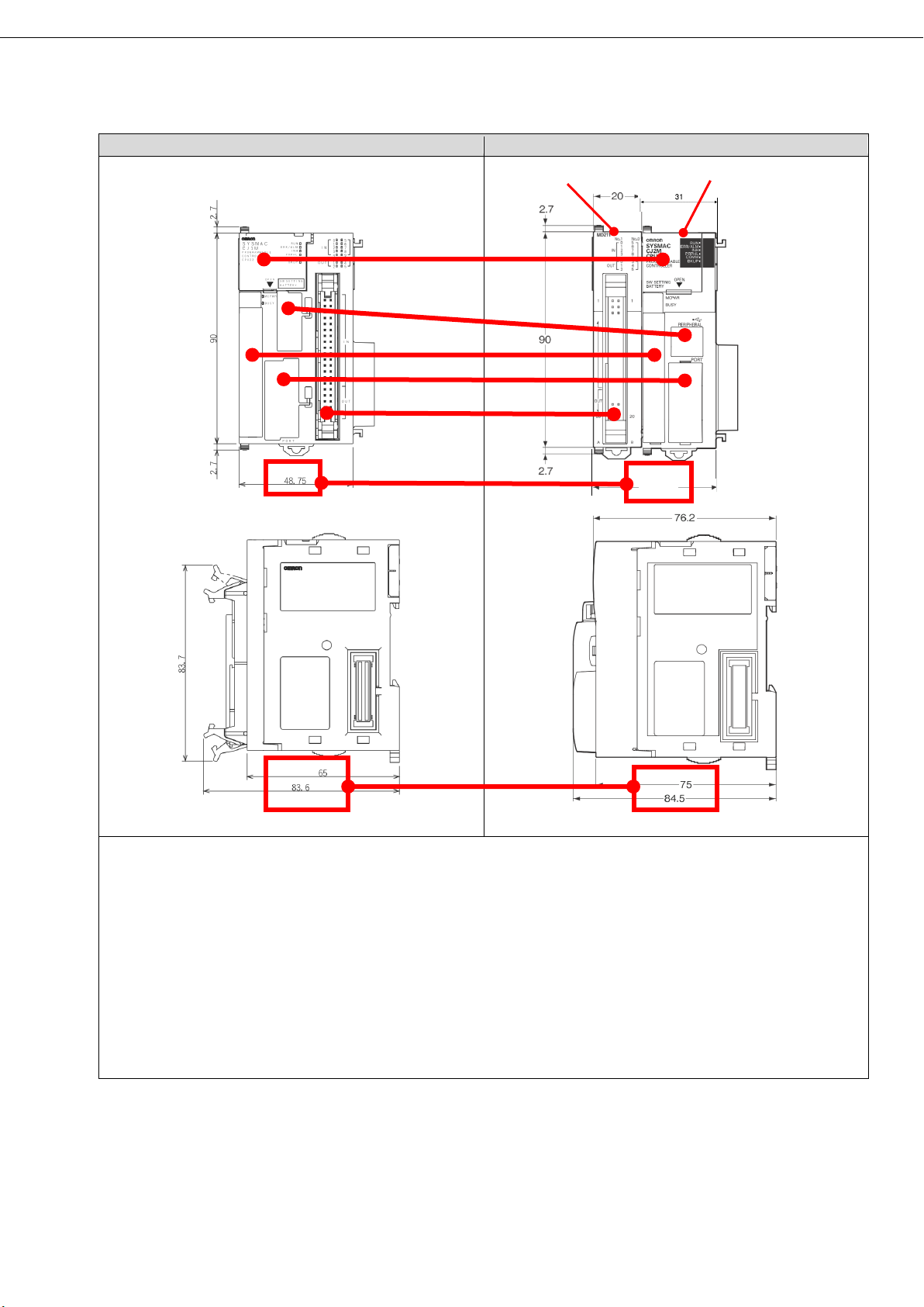
CJ1M-CPU21/22/23
CJ2M-CPU11/12/13/14/15, CJ2M-MD211
CJ2M-MD211 CJ2M-CPU1x
(a) Battery : Common to all models (use CJ1W-BAT01)
(h) Depth dimension : CJ2M is about 10mm larger than CJ1M.
51
(d) Memory Card
(c) Peripheral
(f) Built in I/O
(h) Depth
dimension
(g) Width
dimension
(a) Battery
(b) DIP switch
(e) RS232C
(b) DIP switch : CJ2M does not use SW4 (Setting Peripheral port) (Other switches are common to all models)
(c) Peripheral : CJ2M uses USB communication (See Appendix 2 for functional difference)
(d) Memory Card : Common to all models (use HMC-EFxxx)
(e) RS232C : Pin assignment and functions are common to all models.
(f) Built in I/O :
[Position] CJ1M is located on the right side and CJ2M is located on the left side.
[Wiring] Same. However, do not connect any signal other than “Power supply input (+V) for output” to pin
38. (See Appendix 3 for pin assignment)
[Operation] There are some differences in the operation of the interrupt input. (See Appendix 3 for
functional differences)
(g) Width dimension : CJ2M is about 2mm larger than CJ1M.
11
Page 18

CJ1M-CPU11/12/13-ETN
CJ2M-CPU31/32/33/34/35
(a) Battery : Common to all models (use CJ1W -BAT01)
(g) Depth dimension : CJ2M is about 10mm larger than CJ1M.
(a) Battery
(b) DIP switch
(d) Memory Card
(c) Peripheral
(f) Built in Ethernet
(g) Depth
dimension
(e) RS232C
(b) DIP switch : CJ2M does not use SW 4 (Setting Peripheral port) (Other switches are common to all models)
(c) Peripheral : CJ2M uses USB communication (See Appendix 2 for functional difference)
(d) Memory Card : Common to all models (use HMC-EFxxx)
(e) RS232C : CJ2M requires an optional board (CP1W-CIF01) to be installed.
(f) Built in Ethernet : Some functions cannot be used with the built-in EtherNet/IP of CJ2M (See Appendix 4)
12
Page 19

Function
CJ1M
CJ2M
Description
Programming console
CJ2M cannot use the programming
console.
Tool Bus
Supported
Supported
Host Link
Supported
Not Supported
Use CJ1W-SCUxx, if you use this
function
NT Link (1: N)
Supported
Not Supported
Use CJ1W-SCUxx, if you use this
function
Serial Gateway
Supported
Not Supported
Use CJ1W-SCUxx, if you use this
function
Appendix 2. CJ1M/CJ2M Peripheral function comparison
Supported Not Supported
13
Page 20

Pin layout
Terminal symbol
Input signal type
Pin
No.
Terminal symbol
Input signal type
Pin
No. IN0
24 VDC
1
IN1
24 VDC
2 LD+ 3
LD+
4
0 V/LD-
5 0 V/LD-
6
IN2
24 VDC
7
IN3
24 VDC
8
LD+ 9
LD+
10
0 V/LD-
11 0 V/LD-
12
IN4
24 VDC
13
IN5
24 VDC
14 LD+
15 LD+
16 0 V/LD-
17 0 V/LD-
18
IN6
24 VDC
19
IN7
24 VDC
20
LD+
21 LD+
22 0 V/LD-
23 0 V/LD-
24
IN8
24 VDC
25
IN9
24 VDC
26 LD+
27 LD+
28
0 V/LD-
29 0 V/LD-
30
OUT0
---
31
OUT1
---
32
OUT2
---
33
OUT3
---
34
OUT4
---
35
OUT5
---
36
Power supply input
(+V) for output
---
37
Not used
---
38
Output COM
---
39
Output COM
---
40
Pin layout
Terminal symbol
Input signal type
Pin
No.
Terminal symbol
Input signal type
Pin
No. IN0/IN10
24 VDC
1
IN1/IN11
24 VDC
2
LD+ 3
LD+
4
0 V/LD-
5 0 V/LD-
6
IN2/IN12
24 VDC
7
IN3/IN13
24 VDC
8
LD+ 9
LD+
10 0 V/LD-
11 0 V/LD-
12
IN4/IN14
24 VDC
13
IN5/IN15
24 VDC
14 LD+
15 LD+
16
0 V/LD-
17 0 V/LD-
18
IN6/IN16
24 VDC
19
IN7/IN17
24 VDC
20 LD+
21 LD+
22 0 V/LD-
23 0 V/LD-
24
IN8/IN18
24 VDC
25
IN9/IN19
24 VDC
26
LD+
27 LD+
28
0 V/LD-
29 0 V/LD-
30
OUT0/OUT10
---
31
OUT1/OUT11
---
32
OUT2/OUT12
---
33
OUT3/OUT13
---
34
OUT4/OUT14
---
35
OUT5/OUT15
---
36
Power supply input
(+V) for output
---
37
Power supply input
(+V) for output
---
38
Output COM
---
39
Output COM
---
40
Appendix 3. CJ1M/CJ2M Built in I/O function comparison
(1) Pin assignment
Note. CJ1M does not use Pin No.38, but CJ2M use as “Power supply input +V for output”. CJ2M does not
affect operation if it is not connected. But remove the wiring if it is connecting to another signal.
[CJ1M-CPU21/22/23]
[CJ2M-MD211]
14
Page 21

Interrupt Inputs
CJ1M
CJ2M
Description
Update method for
Updating interrupt
counter SV in Auxiliary
Updating interrupt
counter SV in Auxiliary
and then executing
SKS again to enable
interrupts
Add MSKS instruction, if
Update method for
pdating interrupt
counter PV in Auxiliary
Area
Updating with INI
Change to INI instruction,
for
Updating timing for
nstruction is
count completion
hen PRV instruction is
executed
Make sure that it does
If it is affected, it is
necessary to change the
Operation of interrupt
Counter operation not
Counter operation
errupt
l not occur at count
Make sure that it does
If it is affected, it is
y to change the
program etc.
(2) Functional differences for Interrupt inputs
The following operation differences exist between CJ1M / CJ2M in the interrupt input function. If used,
check that the operation is not affected.
interrupt counter SV
(Counter Mode)
interrupt counter PV
(Counter Mode)
interrupt counter PV
(Counter Mode)
counter when interrupts
are disabled with DI
instruction
Area
・ Updating with INI
instruction
・ U
・Once per count
When PRV i
・
executed
countinued
Area
M
instruction
・Every cycle
When
・
interrupt occurs
・W
continued, but int
wil
completion
you use this operation.
if you use Auxiliary
updating.
not affect operation.
program etc.
not affect operation.
necessar
15
Page 22

Function
CJ1M
Built in Ethernet
CJ2M
Built in EtherNet/IP
Description
Tag data link
communications service
CIP message
communications service
FINS/UDP service
Supported
Supported
FINS/TCP service
Supported
Supported
File transfer (FTP)
Supported
Supported
Web functions
Use CJ1W-ETN21, if you
use this function
Automatic adjustment of
PLC’s internal clock
Simple backup function
Supported
Supported
Error log
Supported
Supported
Response to PING
command
SNMP/SNMP trap
Not supported
Supported
CIDR function for IP
addresses
Not supported
Online connection by
EtherNet/IP using CX-One
Online connection by
CX-One
Online connection by
Configurator
Appendix 4. CJ1M/CJ2M Built in Ethernet function comparison
Not supported Supported
Not supported Supported
Supported Not supported
Supported Supported
Supported Supported
Supported
Not supported Supported
Ethernet (FINS) using
EtherNet/IP using Network
Supported Supported
Not supported Supported
16
Page 23

MEMO
Page 24

2020
Note: Do not use this document to operate the Unit.
P068-E1-03
0320(1210)
 Loading...