

Omron CIMR-V7AZ20P4, CIMR-V7AZ20P1, CIMR-V7AZ20P2, CIMR-V7AZ20P3, CIMR-V7AZ20P5 User Manual
...Page 1
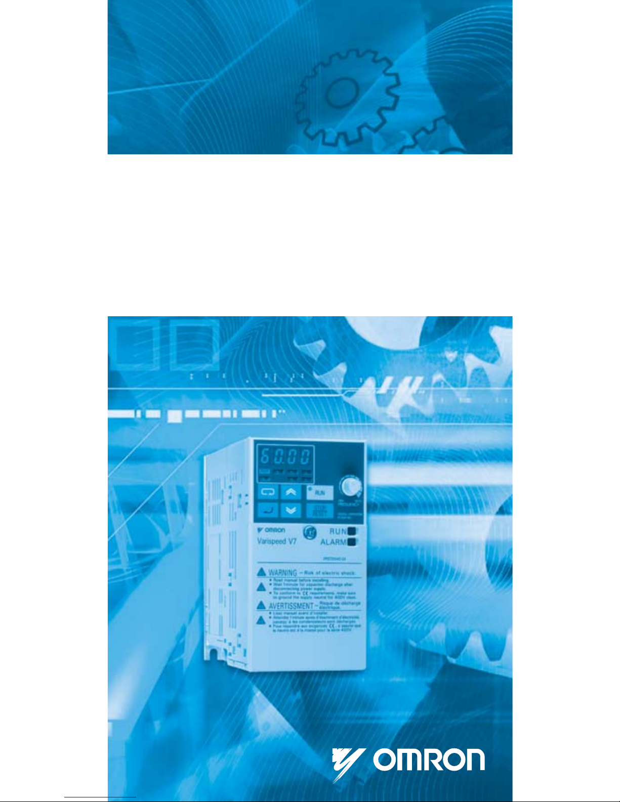
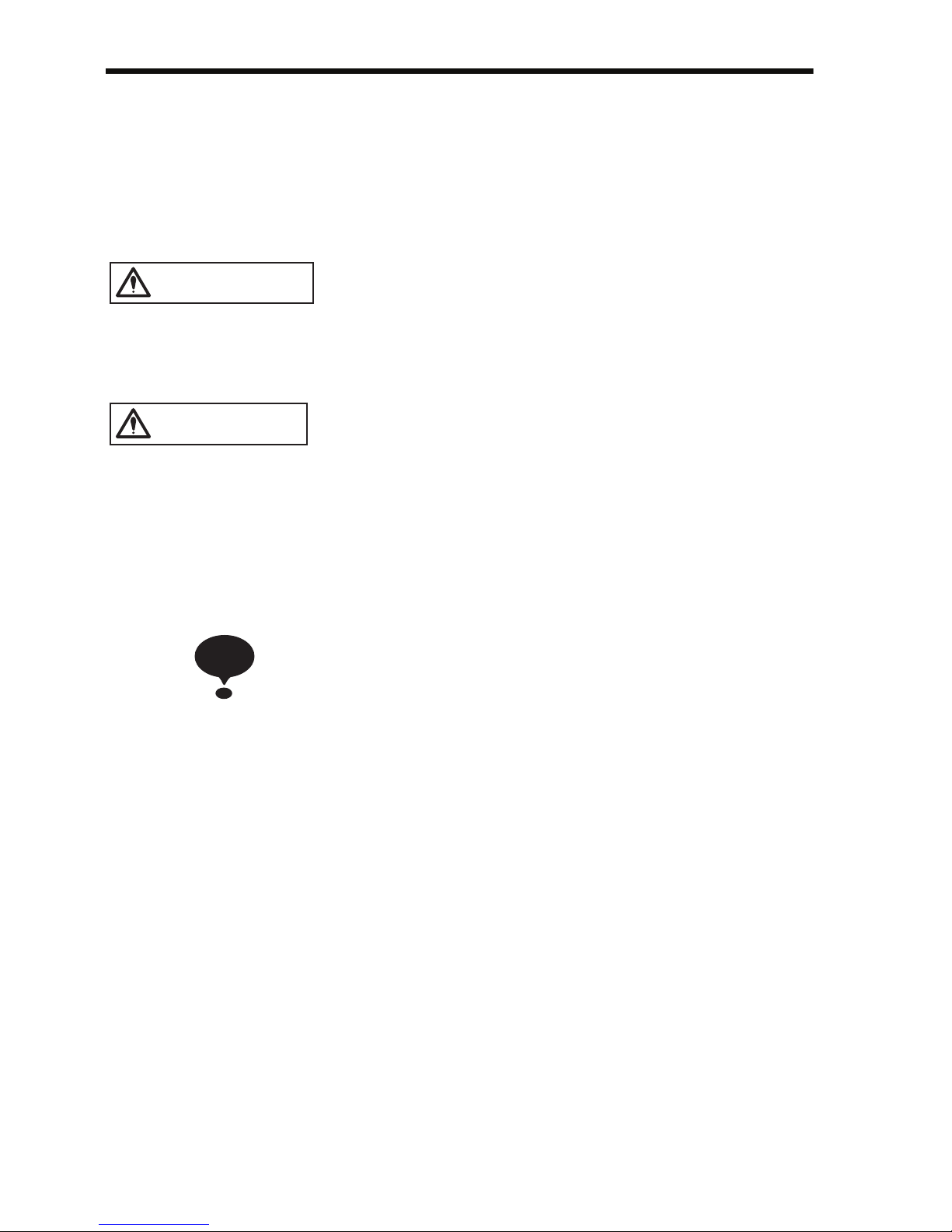
VARISPEED V7
Compact Sensorless Vector Inverter
USER’S MANUAL
Manual No.
TOEPC71060605-0
2-OY
Page 2

1
PREFACE
Omron Yaskawa Motion Control (from now OYMC) V7AZ is a small and
simple Inverter, as easy to use as a contactor. This instruction manual
describes installation, maintenance, inspection, troubleshooting, and specifications of the V7AZ. Read this instruction manual thoroughly before operation.
OMRON YASKAWA MOTION CONTROL
General Precautions
• Some drawings in this manual are shown with protective covers or shields
removed in order to show detail with more clarity. Make sure all covers and
shields are replaced before operating the product.
• This manual may be modified when necessary because of improvements to
the product, modifications, or changes in specifications.
Such modifications are indicated by revising the manual number.
• To order a copy of this manual, or if your copy has been damaged or lost,
contact your OMRON representative.
• OMRON YASKAWA is not responsible for any modification of the product
made by the user, since that will void the guarantee.
Page 3
2
NOTATION FOR SAFETY PRECAUTIONS
Read this instruction manual thoroughly before installation, operation, maintenance, or inspection of the V7AZ. In this manual, safety precautions are classified as either warnings or cautions and are indicated as shown below.
Indicates a potentially hazardous situation which, if not avoided, may result in
death or serious injury.
Indicates a potentially hazardous situation which, if not avoided, may result in
minor or moderate injury or damage to equipment.
It may also be used to alert against unsafe practices.
Even items classified as cautions may result in serious accidents in some situations. Always follow these important precautions.
: Indicates information to insure proper operation.
WARNING
CAUTION
NOTE
Page 4

3
PRECAUTIONS FOR UL/cUL MARKING
• Do not connect or disconnect wiring, or perform signal checks while the
power supply is turned ON.
• The Inverter internal capacitor is still charged even after the power supply
is turned OFF. To prevent electric shock, disconnect all power before servicing the Inverter, and then wait at least one minute after the power supply is disconnected. Confirm that all indicators are OFF before
proceeding.
• Do not perform a withstand voltage test on any part of the Inverter. The
Inverter is an electronic device that uses semiconductors, and is thus vulnerable to high voltage.
• Do not remove the Digital Operator or the blank cover unless the power
supply is turned OFF. Never touch the printed circuit board (PCB) while
the power supply is turned ON.
• This Inverter is not suitable for use on a circuit capable of delivering more
than 18,000 RMS symmetrical amperes, 250 V maximum (200 V Class
Inverters) or 18,000 RMS symmetrical amperes, 480 V maximum (400 V
Class Inverters).
PRECAUTIONS FOR CE MARKINGS
• Only basic insulation to meet the requirements of protection class 1 and
overvoltage category II is provided with control circuit terminals.
Additional insulation may be necessary in the end product to conform to
CE requirements.
• For 400 V Class Inverters, make sure to ground the supply neutral to conform to CE requirements.
• For conformance to EMC directives, refer to the relevant manuals for the
requirements.
Document No. EZZ006543
• Use 75°C copper wire or the equivalent.
CAUTION
Page 5
4
RECEIVING THE PRODUCT
MOUNTING
(Ref. page)
• Do not install or operate any Inverter that is
damaged or has missing parts.
Failure to observe this caution may result in injury or
equipment damage.
18
(Ref. page)
• Lift the Inverter by the heatsinks. When moving
the Inverter, never lift it by the plastic case or the
terminal cover.
Otherwise, the main unit may fall and be damaged.
23
• Mount the Inverter on nonflammable material
(i.e., metal).
Failure to observe this caution may result in a fire.
23
• When mounting Inverters in an enclosure, install
a fan or other cooling device to keep the intake
air temperature below 50 °C (122 °F) for IP20
(open chassis type), or below 40 °C (105 °F) for
NEMA 1 (TYPE 1).
Overheating may cause a fire or damage the Inverter.
23
• The V7AZ generates heat. For effective cooling,
mount it vertically.
Refer to the figure in Choosing a Location to
Mount the Inverter on page 24.
24
CAUTION
CAUTION
Page 6

5
WIRING
(Ref. page)
• Only begin wiring after verifying that the power
supply is turned OFF.
Failure to observe this warning may result in an electric shock or a fire.
28
• Wiring should be performed only by qualified
personnel.
Failure to observe this warning may result in an electric shock or a fire.
28
• When wiring the emergency stop circuit, check
the wiring thoroughly before operation.
Failure to observe this warning may result in injury.
28
• Always ground the ground terminal accord-
ing to the local grounding code.
Failure to observe this warning may result in an electric shock or a fire.
34
• For 400 V Class, make sure to ground the supply neutral.
Failure to observe this warning may result in an electric shock or a fire.
37
• If the power supply is turned ON while the FWD
(or REV) Run Command is being given, the
motor will start automatically.
Turn the power supply ON after verifying that
the RUN signal is OFF.
Failure to observe this warning may result in injury.
37
• When the 3-wire sequence is set, do not make
the wiring for the control circuit unless the multifunction input terminal parameter is set.
Failure to observe this warning may result in injury.
112
WARNING
Page 7

6
(Ref. page)
• Verify that the Inverter rated voltage coincides
with the AC power supply voltage.
Failure to observe this caution may result in personal
injury or a fire.
28
• Do not perform a withstand voltage test on the
Inverter.
Performing withstand voltage tests may damage
semiconductor elements.
28
• To connect a Braking Resistor, Braking Resistor
Unit, or Braking Unit, follow the procedure
described in this manual.
Improper connection may cause a fire.
34
• Always tighten terminal screws of the main circuit and the control circuits.
Failure to observe this caution may result in a malfunction, damage, or a fire.
28
• Never connect the AC main circuit power supply
to output terminals U/T1, V/T2, W/T3, B1, B2, -,
+1, or +2.
The Inverter will be damaged and the guarantee will
be voided.
28
• Do not connect or disconnect wires or connectors while power is applied to the circuits.
Failure to observe this caution may result in injury.
28
• Do not perform signal checks during operation.
The machine or the Inverter may be damaged.
28
• To store a constant with an Enter Command by
communications, be sure to take measures for
an emergency stop by using the external terminals.
Delayed response may cause injury or damage the
machine.
155
CAUTION
Page 8

7
OPERATION
(Ref. page)
• Only turn ON the input power supply after confirming that the Digital Operator or blank cover
(optional) are in place. Do not remove the
Digital Operator or the covers while current is
flowing.
Failure to observe this warning may result in an electric shock.
38
• Never operate the Digital Operator or DIP
switches with wet hands.
Failure to observe this warning may result in an electric shock.
38
• Never touch the terminals while current is flowing, even if the Inverter is stopped.
Failure to observe this warning may result in an electric shock.
38
• When the fault retry function is selected, stand
clear of the Inverter or the load. The Inverter
may restart suddenly after stopping.
(Construct the system to ensure safety, even if the
Inverter should restart.) Failure to observe this warning may result in injury.
84
• When continuous operation after power recovery is selected, stand clear of the Inverter or the
load. The Inverter may restart suddenly after
stopping.
(Construct the system to ensure safety, even if the
Inverter should restart.) Failure to observe this warning may result in injury.
79
• The Digital Operator stop button can be disabled by a setting in the Inverter. Install a separate emergency stop switch.
Failure to observe this warning may result in injury.
98
WARNING
Page 9

8
(Ref. page)
• If an alarm is reset with the operation signal ON,
the Inverter will restart automatically. Reset an
alarm only after verifying that the operation signal is OFF.
Failure to observe this warning may result in injury.
37
• When the 3-wire sequence is set, do not make
the wiring for the control circuit unless the multifunction input terminal parameter is set.
Failure to observe this warning may result in injury.
112
• If n001=5, a Run Command can be received
even while changing a constant. If sending a
Run Command while changing a constant, such
as during a test run, be sure to observe all
safety precautions.
Failure to observe this warning may result in injury.
46, 53
(Ref. page)
• Never touch the heatsinks, which can be
extremely hot.
Failure to observe this caution may result in harmful
burns to the body.
38
• It is easy to change operation speed from low to
high. Verify the safe working range of the motor
and machine before operation.
Failure to observe this caution may result in injury
and machine damage.
38
• Install a holding brake separately if necessary.
Failure to observe this caution may result in injury.
38
WARNING
CAUTION
Page 10

9
• If using an Inverter with an elevator, take safety
measures on the elevator to prevent the elevator from dropping.
Failure to observe this caution may result in injury.
187
• Do not perform signal checks during operation.
The machine or the Inverter may be damaged.
38
• All the constants set in the Inverter have been
preset at the factory. Do not change the settings
unnecessarily.
The Inverter may be damaged.
38
(Ref. page)
CAUTION
Page 11

10
MAINTENANCE AND INSPECTION
(Ref. page)
• Never touch high-voltage terminals on the
Inverter.
Failure to observe this warning may result in an electrical shock.
192
• Disconnect all power before performing maintenance or inspection, and then wait at least one
minute after the power supply is disconnected.
For 400 V Class Inverters, confirm that all indicators are OFF before proceeding.
If the indicators are not OFF, the capacitors are still
charged and can be dangerous.
192
• Do not perform a withstand voltage test on any
part of the V7AZ.
The Inverter is an electronic device that uses semiconductors, and is thus vulnerable to high voltage.
192
• Only authorized personnel should be permitted
to perform maintenance, inspection, or parts
replacement.
(Remove all metal objects (watches, bracelets, etc.)
before starting work.)
(Use tools which are insulated against electrical
shock.)
Failure to observe these warnings may result in an
electric shock.
192
WARNING
Page 12
11
OTHERS
(Ref. page)
• The control PCB employs CMOS ICs.
Do not touch the CMOS elements.
They are easily damaged by static electricity.
192
• Do not connect or disconnect wires, connectors,
or the cooling fan while power is applied to the
circuit.
Failure to observe this caution may result in injury.
192
• Never modify the product.
Failure to observe this warning may result in an electrical shock or
injury and will void the guarantee.
• Do not subject the Inverter to halogen gases, such as fluorine,
chlorine, bromine, and iodine, at any time even during transportation or installation.
Otherwise, the Inverter can be damaged or interior parts burnt.
CAUTION
WARNING
CAUTION
Page 13
12
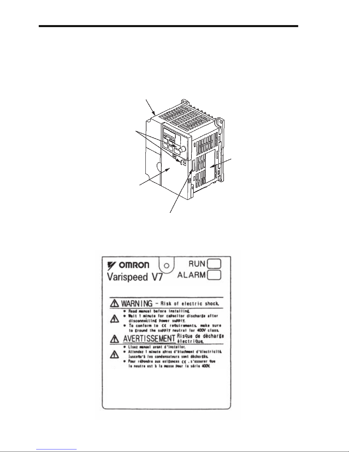
WARNING LABEL
A warning label is provided on the front cover of the Inverter, as shown below.
Follow the warnings when handling the Inverter.
Warning Labels
Plastic Case
Status Indicators
Warning Label Location
Nameplate
Certification Mark
FPST31042-
8
Example of 5.5 kW for 400 V
FPST31042-74
Page 14

13
CONTENTS
NOTATION FOR SAFETY PRECAUTIONS - - - - - - 2
1 Receiving the Product - - - - - - - - - - - - - - - - - - - 18
Checking the Nameplate - - - - - - - - - - - - - - - - - - - - - - - - - - 19
2 Identifying the Parts - - - - - - - - - - - - - - - - - - - - - 20
3 Mounting - - - - - - - - - - - - - - - - - - - - - - - - - - - - 23
Choosing a Location to Mount the Inverter - - - - - - - - - - - - - - 23
Mounting Dimensions - - - - - - - - - - - - - - - - - - - - - - - - - - - - - 24
Mounting/Removing Components- - - - - - - - - - - - - - - - - - - - - 25
Removing the Front Cover- - - - - - - - - - - - - - - - - - - - - - 25
Mounting the Front Cover - - - - - - - - - - - - - - - - - - - - - - 25
Removing the Terminal Cover - - - - - - - - - - - - - - - - - - - 25
Mounting the Terminal Cover - - - - - - - - - - - - - - - - - - - - 26
Removing the Digital Operator - - - - - - - - - - - - - - - - - - - 26
Mounting the Digital Operator - - - - - - - - - - - - - - - - - - - 26
Mounting the Bottom Cover - - - - - - - - - - - - - - - - - - - - - 27
4 Wiring - - - - - - - - - - - - - - - - - - - - - - - - - - - - - - 28
Wire and Terminal Screw Sizes - - - - - - - - - - - - - - - - - - - - - - 30
Wiring the Main Circuits- - - - - - - - - - - - - - - - - - - - - - - - - - - - 34
Wiring the Control Circuits - - - - - - - - - - - - - - - - - - - - - - - - - - 36
Wiring Inspection - - - - - - - - - - - - - - - - - - - - - - - - - - - - - - - - 37
5 Operating the Inverter - - - - - - - - - - - - - - - - - - - 38
Test Run - - - - - - - - - - - - - - - - - - - - - - - - - - - - - - - - - - - - - - 39
Selecting Rotation Direction- - - - - - - - - - - - - - - - - - - - - 41
Operation Check Points- - - - - - - - - - - - - - - - - - - - - - - - 41
Operating the Digital Operator - - - - - - - - - - - - - - - - - - - - - - - 42
Description of Status Indicators - - - - - - - - - - - - - - - - - - 43
Function Indicator Description - - - - - - - - - - - - - - - - - - - - - - - 45
MNTR Multi-function Monitoring - - - - - - - - - - - - - - - - - - 46
Input/Output Terminal Status - - - - - - - - - - - - - - - - - - - - 48
Data Reception Error Display- - - - - - - - - - - - - - - - - - - - 48
Page 15

14
Simple Data Setting - - - - - - - - - - - - - - - - - - - - - - - - - - - - - - -50
6 Programming Features - - - - - - - - - - - - - - - - - - 52
Hardware - - - - - - - - - - - - - - - - - - - - - - - - - - - - - - - - - -52
Software (Constant) - - - - - - - - - - - - - - - - - - - - - - - - - - -52
Constant Setup and Initialization - - - - - - - - - - - - - - - - - - - - - - 53
Constant Selection/Initialization (n001) - - - - - - - - - - - - - 53
Using V/f Control Mode - - - - - - - - - - - - - - - - - - - - - - - - - - - - 55
Adjusting Torque According to Application - - - - - - - - - - -55
Using Vector Control Mode - - - - - - - - - - - - - - - - - - - - - - - - - - 59
Precautions for Voltage Vector Control Application - - - - - 59
Motor Constant Calculation- - - - - - - - - - - - - - - - - - - - - -60
V/f Pattern during Vector Control - - - - - - - - - - - - - - - - - - 61
Switching LOCAL/REMOTE Mode - - - - - - - - - - - - - - - - - - - - 62
How to Select LOCAL/REMOTE Mode - - - - - - - - - - - - - 63
Selecting Run/Stop Commands- - - - - - - - - - - - - - - - - - - - - - - 63
LOCAL Mode - - - - - - - - - - - - - - - - - - - - - - - - - - - - - - -63
REMOTE Mode- - - - - - - - - - - - - - - - - - - - - - - - - - - - - - 64
Operating (Run/Stop Commands) by Communications - - 64
Selecting Frequency Reference - - - - - - - - - - - - - - - - - - - - - - 64
LOCAL Mode - - - - - - - - - - - - - - - - - - - - - - - - - - - - - - -65
REMOTE Mode- - - - - - - - - - - - - - - - - - - - - - - - - - - - - - 65
Setting Operation Conditions - - - - - - - - - - - - - - - - - - - - - - - -66
Autotuning Selection (n139) - - - - - - - - - - - - - - - - - - - - -66
Reverse Run Prohibit (n006)- - - - - - - - - - - - - - - - - - - - -74
Multi-step Speed Selection - - - - - - - - - - - - - - - - - - - - - - 74
Operating at Low Speed- - - - - - - - - - - - - - - - - - - - - - - - 75
Adjusting Speed Setting Signal - - - - - - - - - - - - - - - - - - - 76
Adjusting Frequency Upper and Lower Limits- - - - - - - - - 77
Using Four Acceleration/Deceleration Times - - - - - - - - - 77
Momentary Power Loss Ridethrough Method (n081)- - - - 79
S-curve Selection (n023) - - - - - - - - - - - - - - - - - - - - - - -80
Torque Detection - - - - - - - - - - - - - - - - - - - - - - - - - - - - -81
Frequency Detection Level (n095)- - - - - - - - - - - - - - - - -82
Jump Frequencies (n083 to n086) - - - - - - - - - - - - - - - - - 84
Continuing Operation Using Automatic Retry Attempts - - 84
Frequency Offset Selection (n146) - - - - - - - - - - - - - - - - 85
Page 16

15
Operating a Coasting Motor without Tripping - - - - - - - - - 88
Holding Acceleration/Deceleration Temporarily - - - - - - - 89
External Analog Monitoring(n066) - - - - - - - - - - - - - - - - 90
Calibrating Frequency Meter or Ammerter (n067) - - - - - 91
Using Analog Output (AM-AC) as Pulse Train Signal - - - 91
Carrier Frequency Selection (n080)14kHz max - - - - - - - 94
Operator Stop Key Selection (n007) - - - - - - - - - - - - - - - 98
Second motor selection - - - - - - - - - - - - - - - - - - - - - - - - 99
Selecting the Stopping Method- - - - - - - - - - - - - - - - - - - - - - 106
Stopping Method Selection (n005) - - - - - - - - - - - - - - - 106
Applying DC Injection Braking - - - - - - - - - - - - - - - - - - 107
Simple Positioning Control when Stopping - - - - - - - - - 107
Building Interface Circuits with External Devices - - - - - - - - - 110
Using Input Signals - - - - - - - - - - - - - - - - - - - - - - - - - - 110
Using the Multi-function Analog Inputs - - - - - - - - - - - - 120
Using Output Signals (n057, n058, n059) - - - - - - - - - - 124
Setting Frequency by Current Reference Input - - - - - - - - - - 126
Frequency Reference by Pulse Train Input - - - - - - - - - - - - - 128
Two-wire Sequence 2 - - - - - - - - - - - - - - - - - - - - - - - - - - - - 129
Preventing the Motor from Stalling (Current Limit) - - - - - - - - 131
Stall Prevention during Operation - - - - - - - - - - - - - - - - 133
Decreasing Motor Speed Fluctuation - - - - - - - - - - - - - - - - - 135
Slip Compensation (n002 = 0) - - - - - - - - - - - - - - - - - - 135
Motor Protection - - - - - - - - - - - - - - - - - - - - - - - - - - - - - - - - 136
Motor Overload Detection - - - - - - - - - - - - - - - - - - - - - 136
PTC Thermistor Input for Motor Overheat Protection - - 138
Selecting Cooling Fan Operation - - - - - - - - - - - - - - - - - - - - 141
Using MEMOBUS (MODBUS) Communications - - - - - - - - - 141
MEMOBUS (MODBUS) Communications - - - - - - - - - - 141
Communications Specifications - - - - - - - - - - - - - - - - - 142
Communications Connection Terminal - - - - - - - - - - - - 142
Setting Constants Necessary for Communication- - - - - 143
Message Format- - - - - - - - - - - - - - - - - - - - - - - - - - - - 144
Storing Constants [Enter Command] - - - - - - - - - - - - - 155
Performing Self-test - - - - - - - - - - - - - - - - - - - - - - - - - 158
Using PID Control Mode - - - - - - - - - - - - - - - - - - - - - - - - - - 159
PID Control Selection (n128) - - - - - - - - - - - - - - - - - - - 159
Page 17

16
Analog Position Control with Bi-directional PID Output - 163
Bidirectional Reference Control- - - - - - - - - - - - - - - - - - 164
Using Constant Copy Function - - - - - - - - - - - - - - - - - - - - - - 168
Constant Copy Function - - - - - - - - - - - - - - - - - - - - - - - 168
READ Function - - - - - - - - - - - - - - - - - - - - - - - - - - - - - 170
COPY Function - - - - - - - - - - - - - - - - - - - - - - - - - - - - - 172
VERIFY Function- - - - - - - - - - - - - - - - - - - - - - - - - - - - 174
Inverter Capacity Display - - - - - - - - - - - - - - - - - - - - - - 176
Software No. Display - - - - - - - - - - - - - - - - - - - - - - - - - 178
Display List - - - - - - - - - - - - - - - - - - - - - - - - - - - - - - - - 179
Customer Specific Display Scaling - - - - - - - - - - - - - - - - - - - 181
Selecting Processing for Frequency Reference Loss (n064) - 183
Input/Output Open-phase Detection - - - - - - - - - - - - - - - - - - 184
Undertorque Detection - - - - - - - - - - - - - - - - - - - - - - - - - - - - 185
Using Inverter for Elevating Machines - - - - - - - - - - - - - - - - - 187
Brake ON/OFF Sequence- - - - - - - - - - - - - - - - - - - - - - 187
Stall Prevention during Deceleration - - - - - - - - - - - - - - 189
Settings for V/f Pattern and Motor Constants - - - - - - - - 189
Momentary Power Loss Restart and Fault Restart - - - - 189
I/O Open-phase Protection and Overtorque Detection- - 189
Carrier Frequency - - - - - - - - - - - - - - - - - - - - - - - - - - - 189
External Baseblock Signal - - - - - - - - - - - - - - - - - - - - - 190
Acceleration/Deceleration Time- - - - - - - - - - - - - - - - - - 190
Contactor on the Inverter’s Output-side - - - - - - - - - - - - 190
Using MECHATROLINK-II Communications - - - - - - - - - - - - 191
7 Maintenance and Inspection - - - - - - - - - - - - - 192
Periodic Inspection - - - - - - - - - - - - - - - - - - - - - - - - - - - - - - 193
Part Replacement - - - - - - - - - - - - - - - - - - - - - - - - - - - - - - - 194
Replacement of Cooling Fan- - - - - - - - - - - - - - - - - - - - 195
8 Fault Diagnosis - - - - - - - - - - - - - - - - - - - - - - - 197
Protective and Diagnostic Functions - - - - - - - - - - - - - - - - - - 197
Corrective Actions of Models with Blank Cover - - - - - - - 197
Corrective Actions of Models with Digital Operator - - - - 198
Troubleshooting- - - - - - - - - - - - - - - - - - - - - - - - - - - - - - - - - 212
Page 18

17
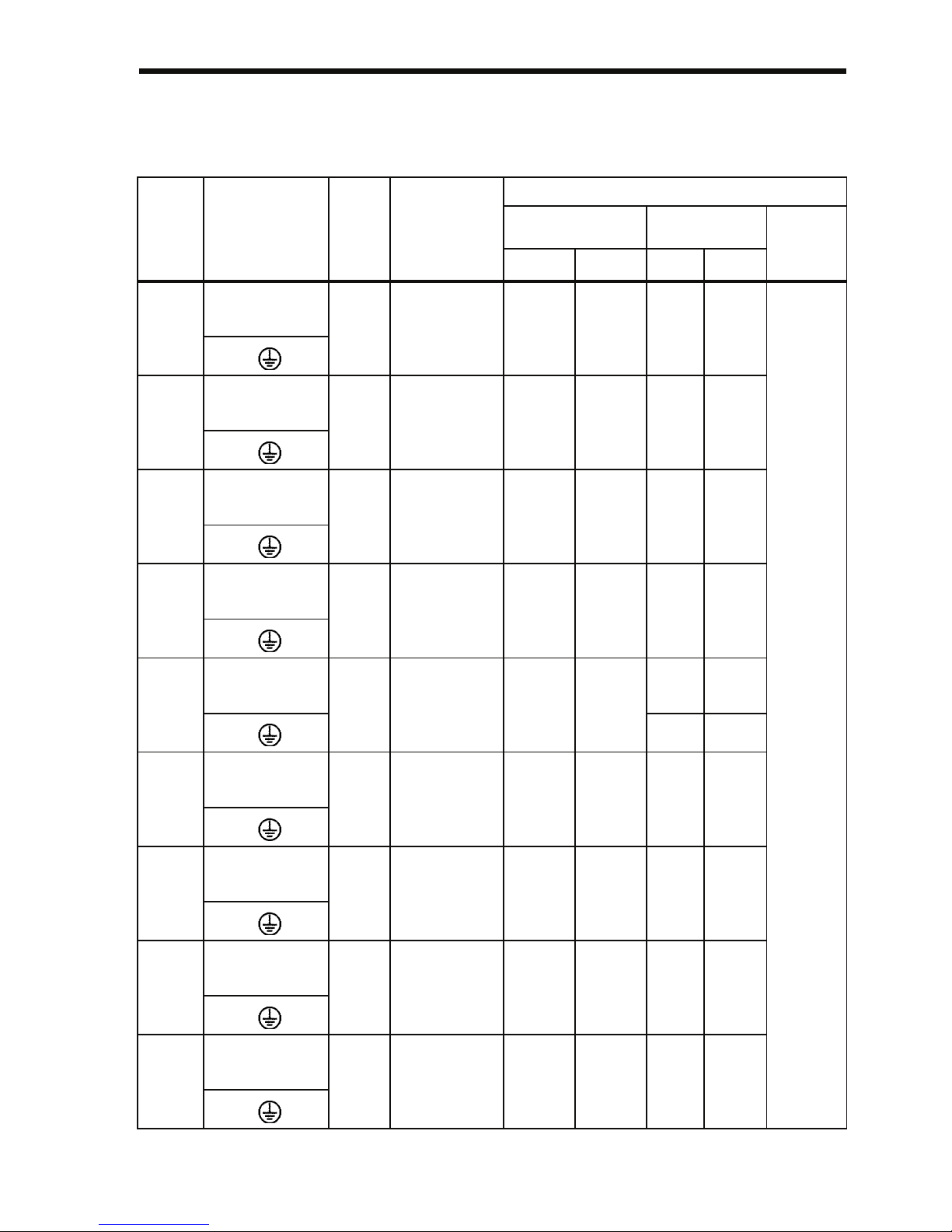
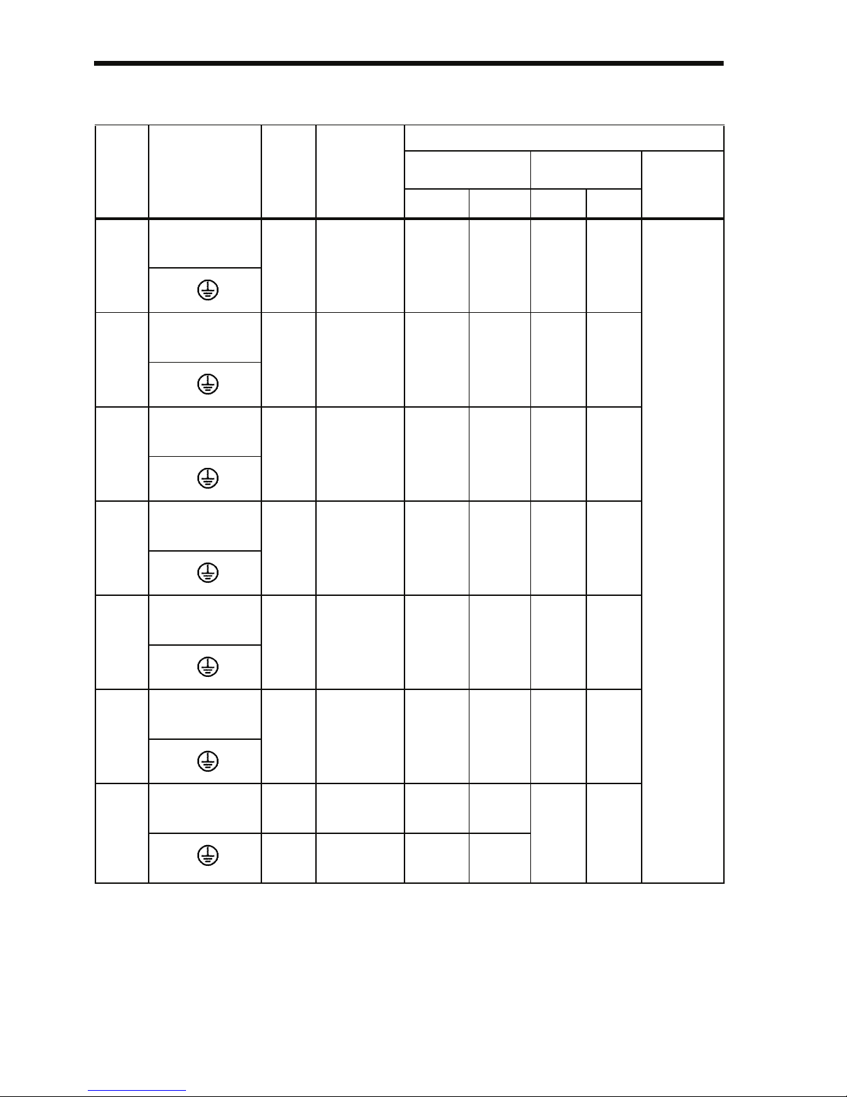
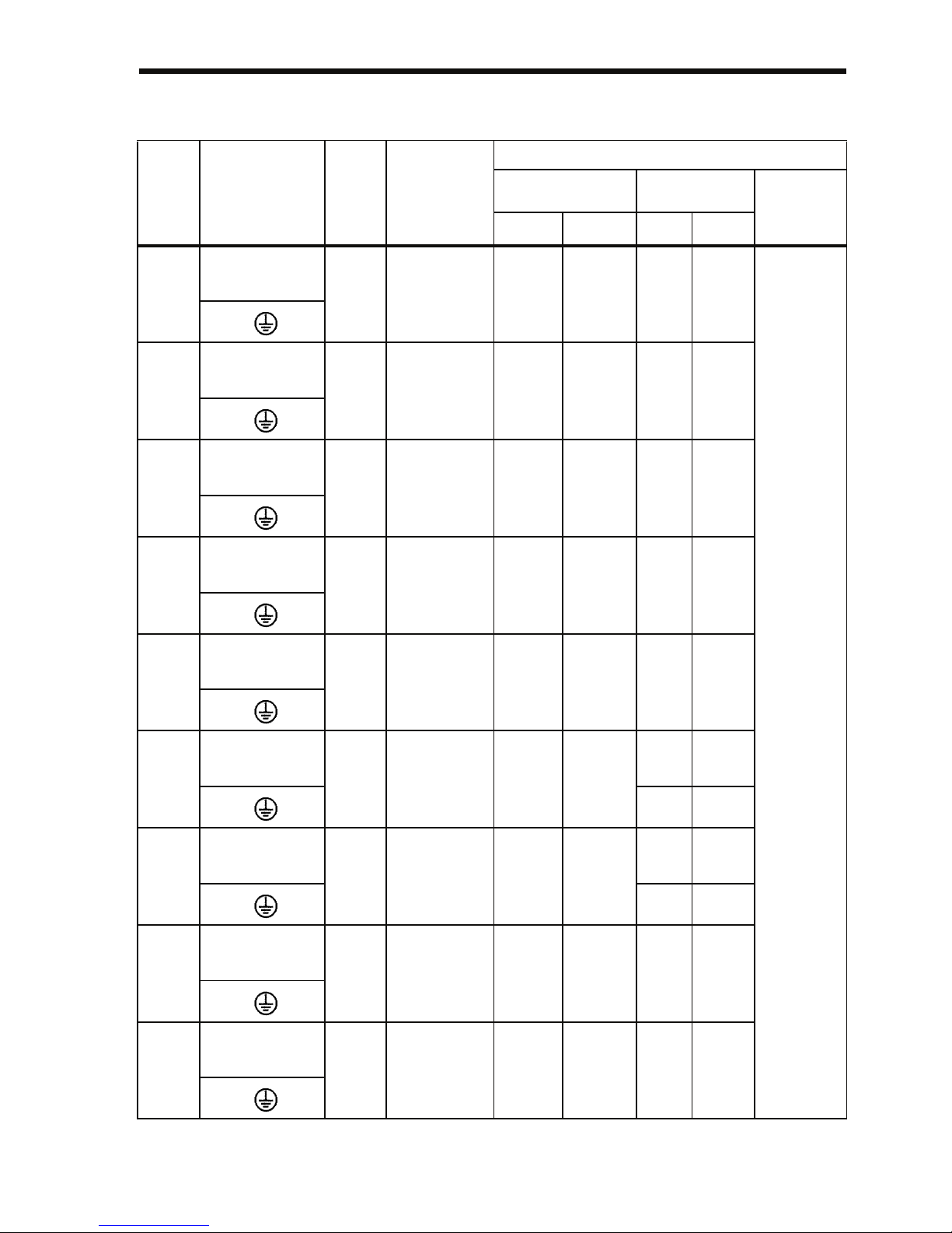
9 Specifications - - - - - - - - - - - - - - - - - - - - - - - - 214
Standard Specifications (200 V Class) - - - - - - - - - - - - - - - - 214
Standard Specifications (400 V Class) - - - - - - - - - - - - - - - - 218
Standard Wiring - - - - - - - - - - - - - - - - - - - - - - - - - - - - - - - - 222
Sequence Input Connection with NPN/PNP Transistor - - - - - 226
Dimensions/Heat Loss - - - - - - - - - - - - - - - - - - - - - - - - - - - 228
Recommended Peripheral Devices- - - - - - - - - - - - - - - - - - - 231
Constants List - - - - - - - - - - - - - - - - - - - - - - - - - - - - - - - - - 234
10 Conformance to CE Markings - - - - - - - - - - - - 247
CE Markings - - - - - - - - - - - - - - - - - - - - - - - - - - - - - - - - - - 247
Requirements for Conformance to CE Markings - - - - - - - - - 247
Low Voltage Directive - - - - - - - - - - - - - - - - - - - - - - - - 247
EMC Directive - - - - - - - - - - - - - - - - - - - - - - - - - - - - - 248
Page 19

18
1 Receiving the Product
Do not install or operate any Inverter that is damaged or has missing parts.
Failure to observe this caution may result in injury
or equipment damage.
After unpacking the V7AZ, check the following.
• Verify that the model number matches your purchase order or packing
slip.
• Check the Inverter for physical damage that may have occurred during
shipping.
If any part of V7AZ is missing or damaged, call for service immediately.
CAUTION
Page 20

1 Receiving the Product
19
Checking the Nameplate
Example for 3-phase, 200-VAC, 0.1-kW (0.13 HP) Inverter
for European standards
Inverter Model
Input Spec.
Output Spec.
Lot No.
Serial No.
Inverter
V7AZ Series
Software Number
Specifications
Model
B
2
4
Single-phase 200 VAC
Three-phase 200 VAC
Three-phase 400 VAC
0P1
0P2
0P4
0.1 kW
0.25 kW
0.55 kW
0P7
1P5
2P2
1.1 kW
1.5 kW
2.2 kW
3P0
4P0
4.0 kW
3.0 kW
0.37 kW
0.55 kW
1.1 kW
1.5 kW
2.2 kW
4.0 kW
Applicable maximum motor output
200 V class 400 V class
No.
Protective structure
0
Open chassis
(IP20, IP00)*
1
1
Enclosed wall-mounted
(NEMA1)*
2
No.
Voltage Class
B
2
4
Single-phase 200 VAC
Three-phase 200 VAC
Three-phase 400 VAC
No.
Specifications
Z
European standards
0P1
0P2
0P4
0.1 kW
0.25 kW
0.55 kW
0P7
1P5
2P2
1.1 kW
1.5 kW
2.2 kW
3P0
4P0
4.0 kW
3.0 kW
0.37 kW
0.55 kW
1.1 kW
1.5 kW
2.2 kW
4.0 kW
Applicable maximum motor output
200 V class 400 V class
CIMR-V7AZ20P1
No.
Type
A With Digital Operator (with potentiometer)
A
5.5 kW
5P5
7P5
7.5 kW
5.5 kW
7.5 kW
5.5 kW
5P5
7P5
7.5 kW
5.5 kW
7.5 kW
20P10
Z
Note: Contact your OMRON representatives
for models without heatsinks.
*1: Inverters with outputs 0P1 to 3P7 are rated
IP20. Be sure to remove the top and bottom
covers if using open-chassis mounted Inverters
with a 5P5 or 7P5 output.
*2: A NEMA 1 rating is optional for Inverters with
outputs 0P1 to 3P7 but standard for 5P5 or 7P5.
Mass
Inverter Software Version
The inverter software version can be read out from the monitor parameter
U-10 or parameter n179. The parameter shows the last for digits of the
software number (e.g. display is“5740”for the software version VSP015740).
The manual describes the functionality of the Inverter software version
VSP015740 (0.1 to 4.0 kW) and VSP105750 (5.5 and 7.5 kW). Older software
versions do not support all described functions. Check the software version
before starting to work with this manual.
Page 21
20
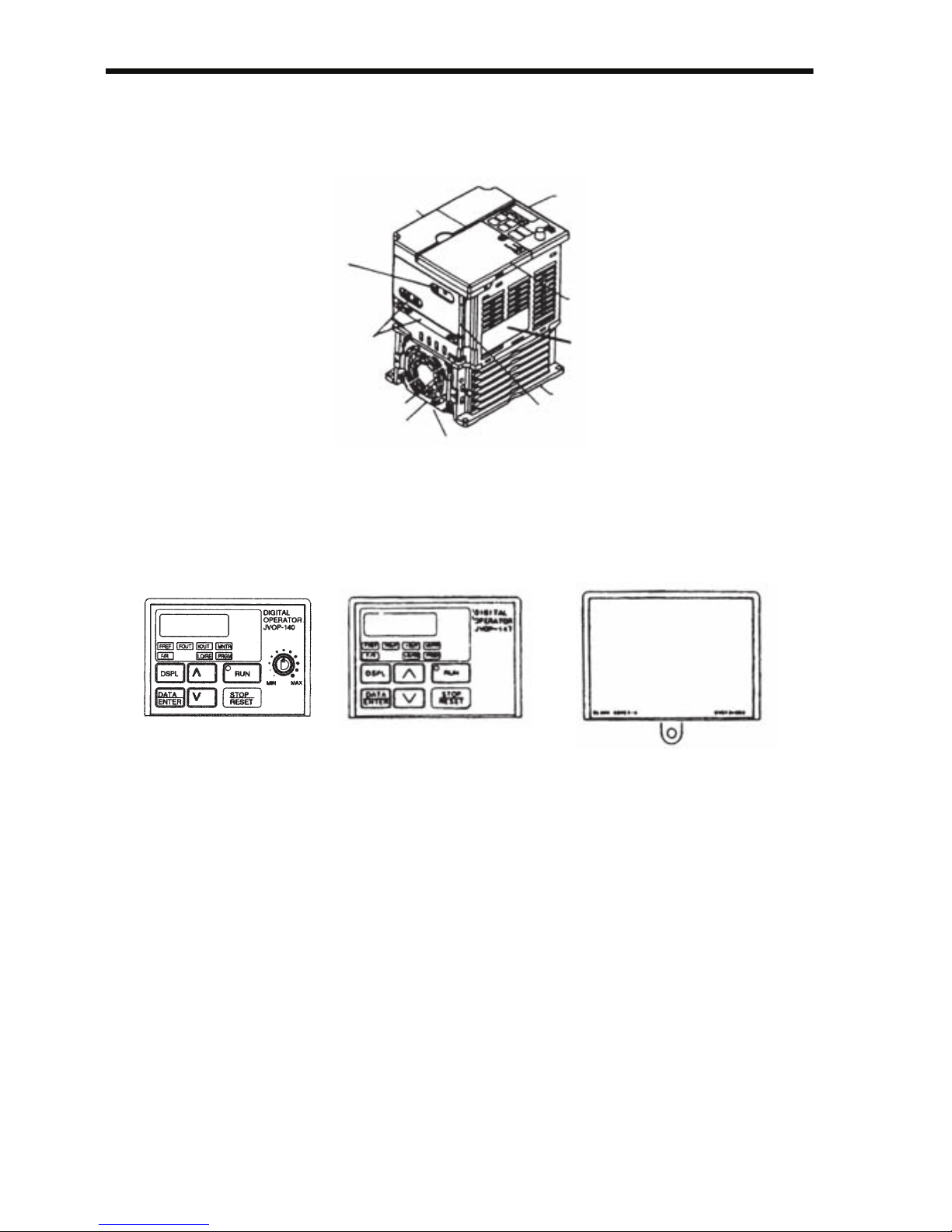
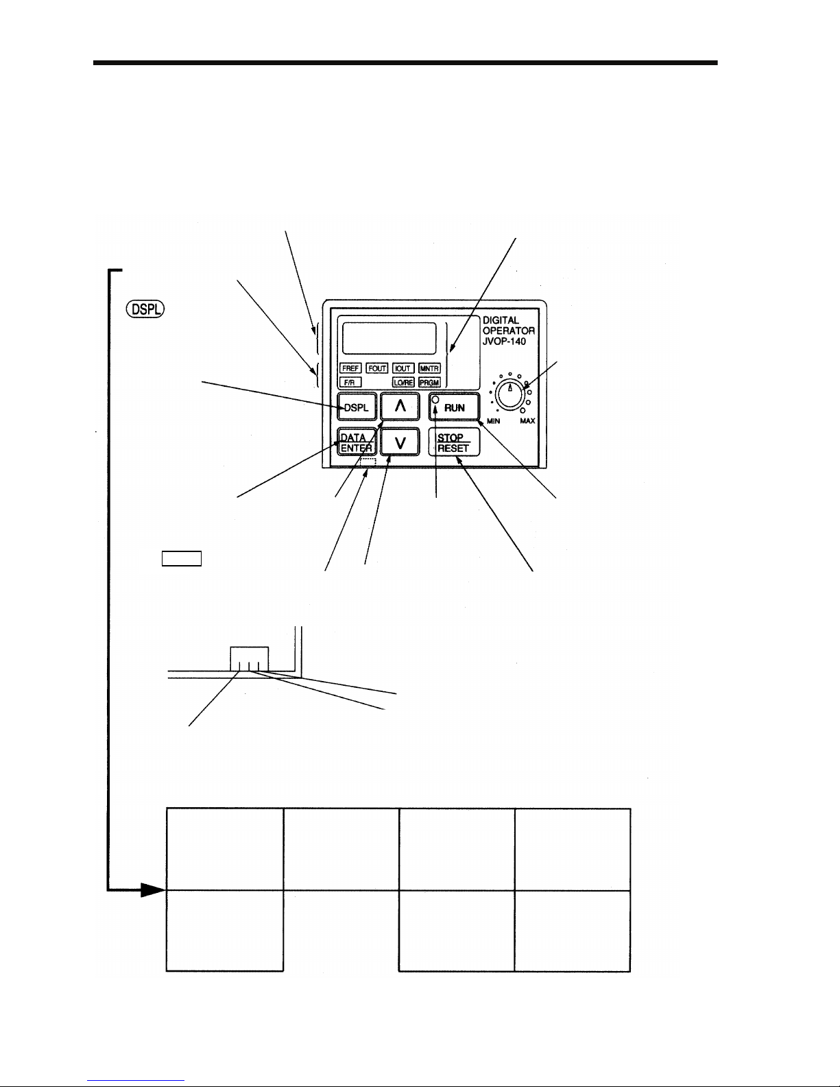
2 Identifying the Parts
Digital Operator
(with potentiometer)
JVOP-140
Used for setting or
changing constants.
Frequency can be set
using the potentiometer.
Digital Operator
(without potentiometer)
JVOP-147
Used for setting or
changing constants.
Blank cover
In models without a
Digital Operator, the
blank cover is mounted
in place of the Digital
Operator.
Terminal Cover
Digital Operator
Front Cover
Nameplate
Heatsink
Bottom Cover
Wiring Holes
for Main Circuit
Wiring Holes
for Control Circuit
Ground Terminal
Cooling Fan
Fan Cover
Page 22
2 Identifying the Parts
21
V7AZ Inverters with the Covers Removed
Example for 3-phase (200 V Class, 1.5 kW) Inverter
Example for 3-phase (200 V Class, 0.1 kW) Inverter
Frequency-setting Potentiometer
Inverter Operation Status Indicators
Short-circuit
Bar
Ground Terminals
Main Circuit Terminal Block
Control Circuit Terminal Block
Input Polarity
Switch
Ground Terminals
Terminal Resistor Switch for
Communication Circuit
Voltage/Current Change Switch for
Analog Frequency Reference Input
Frequency-setting Potentiometer
Inverter Operation Status Indicators
Short-circuit
Bar
Main Circuit Terminal Block
Control Circuit Terminal Block
Input Polarity
Switch
Terminal Resistor Switch for
Communication Circuit
Voltage/Current Change Switch for
Analog Frequency Reference Input
Page 23
22
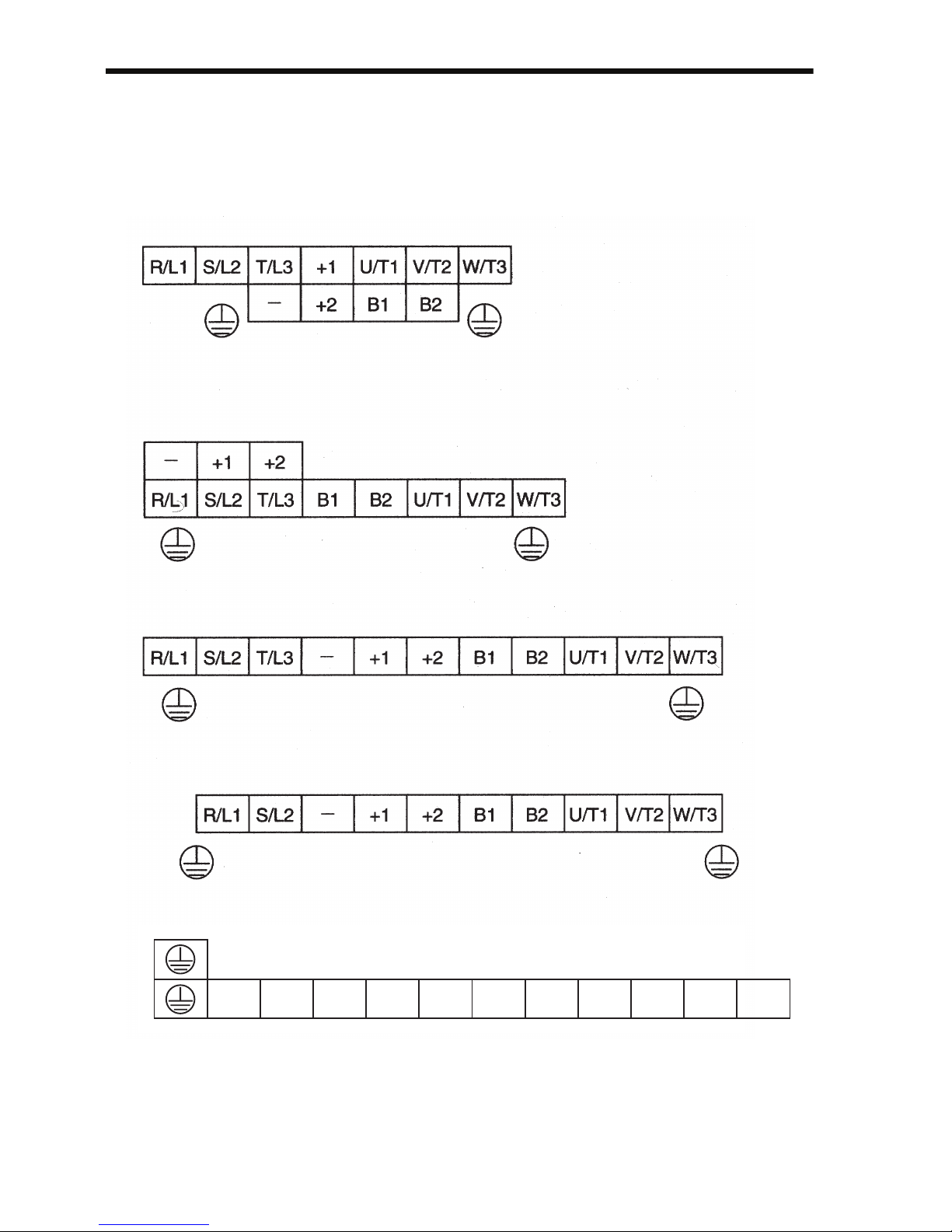
Main Circuit Terminal Arrangement
The terminal arrangement of the main circuit terminals depends on the
Inverter model.
CIMR-V7AZ20P1 to 20P7, B0P1 to B0P4
CIMR-V7AZ21P5, 22P2, B0P7, B1P5, 40P2 to 42P2
CIMR-V7AZ24P0, B2P2, 43P0, 44P0
CIMR-V7AZB4P0
CIMR-V7AZ25P5, 27P5, 45P5, 47P5
R/L1 S/L2 T/L3 㧙 +1 +2 B1 B2 U/T1 V/T2 W/T3
Page 24

3 Mounting
23
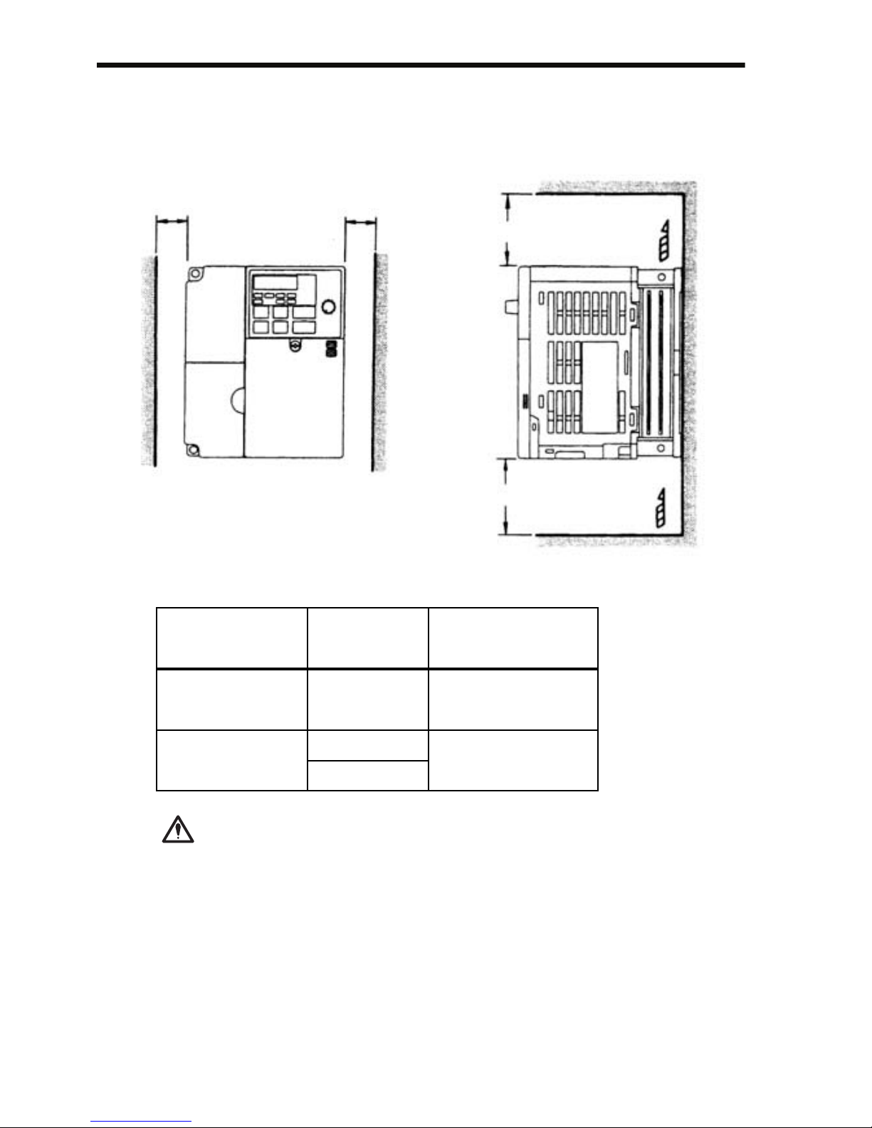
3 Mounting
Choosing a Location to Mount the Inverter
Be sure the Inverter is protected from the following conditions.
• Extreme cold and heat. Use only within the specified ambient temperature range:
−10 to 50 °C (14 to 122 °F) for IP20 (open chassis type),
−10 to 40 °C (14 to 105 °F) for NEMA 1 (TYPE 1)
• Rain and moisture
• Oil sprays and splashes
• Salt spray
• Direct sunlight (Avoid using outdoors.)
• Corrosive gases (e.g., sulfurized gas) or liquids
• Dust or metallic particles in the air
• Physical shock or vibration
• Magnetic noise (Examples: Welding machines, power devices, etc.)
• High humidity
• Radioactive substances
• Combustibles, such as thinner or solvents
Page 25
24
Mounting Dimensions
To mount the V7AZ, the dimensions shown below are required.
• Lift the Inverter by the heatsinks. When moving the
Inverter, never lift it by the plastic case or the terminal cover.
Otherwise, the main unit may fall and be damaged.
• The V7AZ generates heat. For effective cooling,
mount it vertically.
Air
Air
aa
100 mm (3.94 in.) or more
100 mm (3.94 in.) or more
Voltage Class
(V)
Max. Applicable
Motor Capacity
(kW)
Length a
200 V Single-phase
3-phase
400 V 3-phase
3.7 kW or less
30 mm (1.18 in.) min.
50 mm (1.97 in.) min.
200 V 3-phase
400 V 3-phase
5.5 kW
7.5 kW
CAUTION
Page 26
3 Mounting
25
• The same space is required horizontally and vertically and
right and left for both Open Chassis (IP00, IP20) and
Enclosed Wall-mounted (NEMA 1) Inverters.
• Always remove the top and bottom covers before installing a 200 or 400 V Class Inverter with an output of 5.5/7.5
kW in a panel.
Mounting/Removing Components
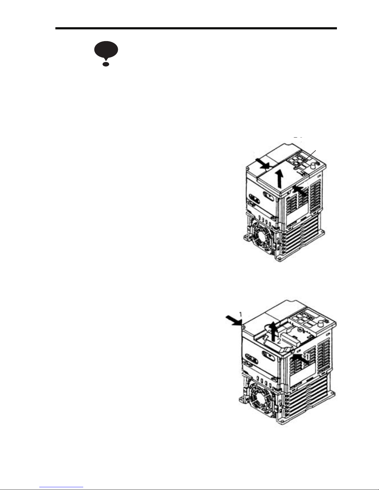
Removing and Mounting the Digital Operator and Covers
Removing the Front Cover
Use a screwdriver to loosen the screw
(section A) on the front cover. (To prevent loss, this screw cannot be
removed.) Then press the right and left
sides in direction 1 and lift the front
cover in direction 2.
Mounting the Front Cover
Mount the front cover by reversing the
order of the above procedure for
removal.
Removing the Terminal Cover
• 200 V class Inverters with 1.1 kW
and more and all 400 V class
Inverters:
After removing the front cover,
press the right and left sides of the
terminal cover in direction 1 and lift
the terminal cover in direction 2.
NOTE
1
1
2
A
Page 27
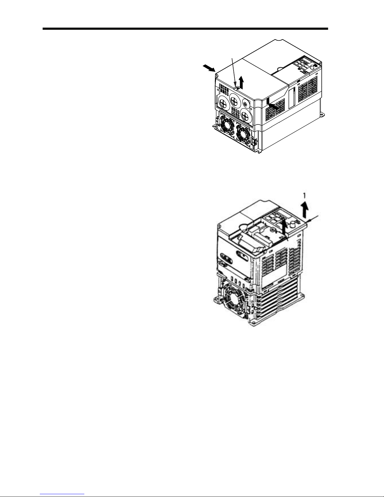
26
• Inverters of 5.5 and 7.5 kW:
Use a screwdriver to loosen
the screw (section B) on the
terminal cover surface. (To
prevent loss, this screw cannot
be removed.) Then press the
right and left sides in direction
1 and lift the terminal cover in
direction 2.
Mounting the Terminal
Cover
Mount the terminal cover by
reversing the order of the above procedure for removal.
Removing the Digital Operator
After removing the front cover, (follow the procedure on page 25) lift the
upper and lower sides (section C) of
the right side of the Digital Operator
in direction 1.
Mounting the Digital Operator
Mount the Digital Operator by reversing the order of the above procedure
for removal.
1
1
2
B
C
C
Page 28
3 Mounting
27
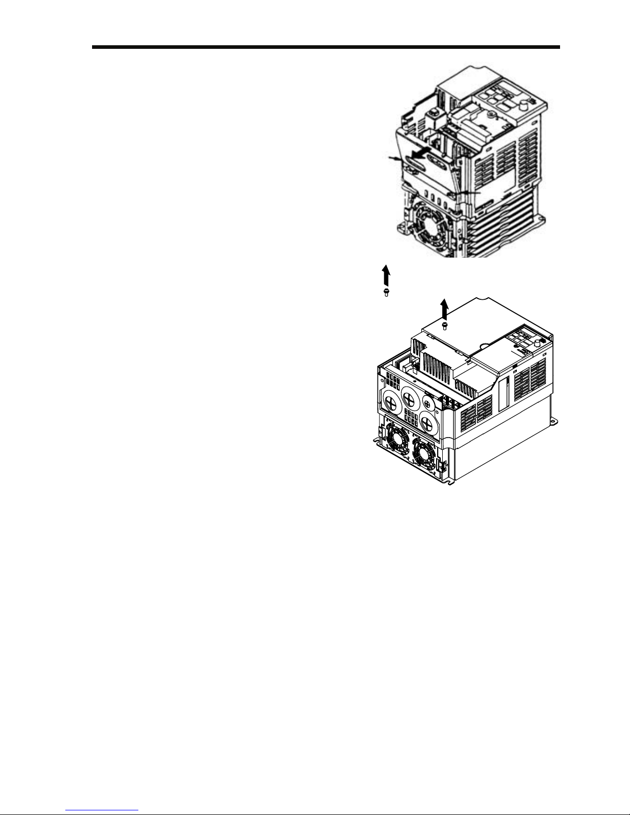
Removing the Bottom Cover
• 200 V class Inverters with 1.1 kW
and more and all 400 V class
Inverters:
After removing the front cover and
the terminal cover, tilt the bottom
cover in direction 1 with section A
as a supporting point.
• Inverters of 5.5 and 7.5 kW
After removing the terminal cover,
use a screwdriver to loosen the
mounting screw in direction 1.
Mounting the Bottom Cover
Mount the bottom cover by reversing
the order of the above procedure for
removal.
A
A
1
1
Page 29

28
4 Wiring
• Only begin wiring after verifying that the power supply is turned OFF.
Failure to observe this warning may result in an
electric shock or a fire.
• Wiring should be performed only by qualified personnel.
Failure to observe this warning may result in an
electric shock or a fire.
• When wiring the emergency stop circuit, check the
wiring thoroughly before operation.
Failure to observe this warning may result in injury.
• For the 400 V Class, make sure to ground the supply
neutral.
Failure to observe this warning may result in an
electric shock or a fire.
• Verify that the Inverter rated voltage coincides with
the AC power supply voltage.
Failure to observe this caution may result in personal injury or a fire.
• Do not perform a withstand voltage test on the
Inverter.
Performing withstand voltage tests may damage
semiconductor elements.
• Always tighten terminal screws of the main circuit
and the control circuits.
Failure to observe this caution may result in a malfunction, damage, or a fire.
• Never connect the AC main circuit power supply to
output terminals U/T1, V/T2, W/T3, B1, B2, -, +1,
or +2.
The Inverter will be damaged and the guarantee will
be voided.
• Do not connect or disconnect wires or connectors
while power is applied to the circuits.
Failure to observe this caution may result in injury.
• Do not perform signal checks during operation.
The machine or the Inverter may be damaged.
• To store a constant with an Enter Command by communications, be sure to take measures for an emergency stop by using the external terminals.
WARNING
CAUTION
Page 30

4 Wiring
29
Delayed response may cause injury or damage the
machine.
Wiring Instructions
1. Always connect the power supply for the main circuit
inputs to the power input terminals R/L1, S/L2, and T/L3
(R/L1, S/L2 for single-phase power) via a molded-case
circuit breaker (MCCB) or a fuse. Never connect the
power supply to terminals U/T1, V/T2, W/T3, B1, B2, −,
+1, or +2. The Inverter may be damaged.
For single-phase Inverters, always use terminals R/L1 and
S/L2. Never connect terminal T/L3. Fuses must be of ULclass RK5 fuse or an equivalent.
Refer to page 231 for recommended peripheral devices.
Inverter Power Supply Connection Terminals
2. If the wiring distance between Inverter and motor is long,
reduce the Inverter carrier frequency. For details, refer to
Carrier Frequency Selection (n080)14kHz max on page
94.
3. Control wiring must be less than 50 m (164 ft) in length
and must be separated from power wiring. Use shielded
twisted-pair cable when inputting the frequency signal
externally.
4. Only basic insulation to meet the requirements of protection class 1 and overvoltage category II is provided with
control circuit terminals. Additional insulation may be
necessary in the end product to conform to CE requirements.
5. Closed-loop connectors should be used when wiring to the
main circuit terminals.
200-V 3-phase Input
Power Supply Speci-
fication Inverters
CIMR-V72
200-V Single Input
Power Supply Speci-
fication Inverters
CIMR-V7B
400-V 3-phase Input
Power Supply Speci-
fication Inverters
CIMR-V74
Connect to R/L1,
S/L2, and T/L3.
Connect to R/L1 and
S/L2.
Connect to R/L1,
S/L2, and T/L3.
NOTE
Page 31

30
6. Voltage drop should be considered when determining the
wire size.
Voltage drop can be calculated using the following equation:
Phase-to-phase voltage drop (V)
= × Wire resistance (Ω/km) × Wiring distance (m) ×
Current
(A) × 10
-3
Select a wire size so that voltage drop will be less than 2%
of the normal rated voltage.
7. If the Inverter is connected to a power transformer exceeding 600 kVA, excessive peak current may flow into the
input power supply circuit, and break the converter section. In this case, attach an AC reactor (optional) to the
Inverter input side, or a DC reactor (optional) to the DC
reactor connection terminal.
Wire and Terminal Screw Sizes
1. Control Circuits
Model Terminal
Symbols
Screws Tightening
To rq ue
N•m (lb•in)
Wires
Applicable Size Recom-
mended Size
Typ e
mm
2
AWG
mm
2
AWG
Same
for all
models
MA, MB, MC M3 0.5 to 0.6
(4.44 to 5.33)
Twi sted w ire s :
0.5 to 1.25,
Single: 0.5 to 1.25
20 to 16,
20 to 16
0.75 18 Shielded or
equivalent
S1 to S7, P1,
P2, SC, PC,
R+, R-, S+, S-,
FS, FR, FC,
AM, AC, RP
M2 0.22 to 0.25
(1.94 to 2.21)
Twi sted w ire s :
0.5 to 0.75,
Single: 0.5 to 1.25
20 to 18,
20 to 16
0.75 18
3
Page 32
4 Wiring
31
2. Main Circuits
200 V Class 3-phase Input Inverters
Note: The wire size is given for copper wire at 75°C (160°F).
Model Terminal Symbols Screws Tightening
Tor qu e
N•m (lb•in)
Wires
Applicable Size Recommended
Size
Type
mm
2
AWG
mm
2
AWG
CIMR-
V7ΑΖ
20P1
R/L1, S/L2, T/L3, -
, +1, +2, B1, B2,
U/T1, V/T2, W/T3
M3.5 0.8 to 1.0
(7.1 to 8.88)
0.75 to 2 18 to 14 2 14 600-V
vinyl-
sheathed
or equiva-
lent
CIMR-
V7ΑΖ
20P2
R/L1, S/L2, T/L3, -
, +1, +2, B1, B2,
U/T1, V/T2, W/T3
M3.5 0.8 to 1.0
(7.1 to 8.88)
0.75 to 2 18 to 14 2 14
CIMR-
V7ΑΖ
20P4
R/L1, S/L2, T/L3, -
, +1, +2, B1, B2,
U/T1, V/T2, W/T3
M3.5 0.8 to 1.0
(7.1 to 8.88)
0.75 to 2 18 to 14 2 14
CIMR-
V7ΑΖ
20P7
R/L1, S/L2, T/L3, -
, +1, +2, B1, B2,
U/T1, V/T2, W/T3
M3.5 0.8 to 1.0
(7.1 to 8.88)
0.75 to 2 18 to 14 2 14
CIMR-
V7ΑΖ
21P5
R/L1, S/L2, T/L3, -
, +1, +2, B1, B2,
U/T1, V/T2, W/T3
M4 1.2 to 1.5
(10.65 to 13.31)
2 to 5.5 14 to 10 2 14
3.5 12
CIMR-
V7ΑΖ
22P2
R/L1, S/L2, T/L3, -
, +1, +2, B1, B2,
U/T1, V/T2, W/T3
M4 1.2 to 1.5
(10.65 to 13.31)
2 to 5.5 14 to 10 3.5 12
CIMR-
V7ΑΖ
24P0
R/L1, S/L2, T/L3, -
, +1, +2, B1, B2,
U/T1, V/T2, W/T3
M4 1.2 to 1.5
(10.65 to 13.31)
2 to 5.5 14 to 10 5.5 10
CIMR-
V7ΑΖ
25P5
R/L1, S/L2, T/L3, -
, +1, +2, B1, B2,
U/T1, V/T2, W/T3
M5 2.5
(22.13)
5.5 to 8 10 to 8 8 8
CIMR-
V7ΑΖ
27P5
R/L1, S/L2, T/L3, -
, +1, +2, B1, B2,
U/T1, V/T2, W/T3
M5 2.5
(22.13)
5.5 to 8 10 to 8 8 8
Page 33
32
200 V Class Single-phase Input Inverters
Note: 1. The wire size is given for copper wire at 75°C (160°F).
2. Do not use terminal T/L3 on Inverters with single-phase input.
Model Terminal Symbols Screws Tightening
To rq ue
N•m (lb•in)
Wires
Applicable Size Recommended
Size
Typ e
mm
2
AWG
mm
2
AWG
CIMR-
V7ΑΖ
B0P1
R/L1, S/L2, T/L3,
-, +1, +2, B1, B2,
U/T1, V/T2, W/T3
M3.5 0.8 to 1.0
(7.1 to 8.88)
0.75 to 2 18 to 14 2 14 600-V vinylsheathed or
equivalent
CIMR-
V7ΑΖ
B0P2
R/L1, S/L2, T/L3,
-, +1, +2, B1, B2,
U/T1, V/T2, W/T3
M3.5 0.8 to 1.0
(7.1 to 8.88)
0.75 to 2 18 to 14 2 14
CIMR-
V7ΑΖ
B0P4
R/L1, S/L2, T/L3,
-, +1, +2, B1, B2,
U/T1, V/T2, W/T3
M3.5 0.8 to 1.0
(7.1 to 8.88)
0.75 to 2 18 to 14 2 14
CIMR-
V7ΑΖ
B0P7
R/L1, S/L2, T/L3,
-, +1, +2, B1, B2,
U/T1, V/T2, W/T3
M4 1.2 to 1.5
(10.65 to
13.31)
2 to 5.5 14 to 10 3.5 12
CIMR-
V7ΑΖ
B1P5
R/L1, S/L2, -, +1,
+2, B1, B2, U/T1,
V/T2, W/T3
M4 1.2 to 1.5
(10.65 to
13.31)
2 to 5.5 14 to 10 5.5 10
CIMR-
V7ΑΖ
B2P2
R/L1, S/L2, -, +1,
+2, B1, B2, U/T1,
V/T2, W/T3
M4 1.2 to 1.5
(10.65 to
13.31)
2 to 5.5 14 to 10 5.5 10
CIMR-
V7ΑΖ
B4P0
R/L1, S/L2, -, +1,
+2, B1, B2, U/T1,
V/T2, W/T3
M5 3.0 (26.62) 3.5 to 8 12 to 8 8 8
M4 1.2 to 1.5
(10.65 to
13.31)
2 to 8 14 to 8
Page 34
4 Wiring
33
400 V Class 3-phase Input Inverters
Note: The wire size is given for copper wire at 75°C (160°F).
Model Terminal Sym-
bols
Screws Tightening
Tor qu e
N•m (lb•in)
Wires
Applicable Size Recommended
Size
Typ e
mm
2
AWG
mm
2
AWG
CIMR-
V7ΑΖ
40P2
R/L1, S/L2, T/L3,
-, +1, +2, B1, B2,
U/T1, V/T2, W/T3
M4 1.2 to 1.5
(10.65 to
13.31)
2 to 5.5 14 to 10 2 14 600-V vinyl-
sheathed or
equivalent
CIMR-
V7ΑΖ
40P4
R/L1, S/L2, T/L3,
-, +1, +2, B1, B2,
U/T1, V/T2, W/T3
M4 1.2 to 1.5
(10.65 to
13.31)
2 to 5.5 14 to 10 2 14
CIMR-
V7ΑΖ
40P7
R/L1, S/L2, T/L3,
-, +1, +2, B1, B2,
U/T1, V/T2, W/T3
M4 1.2 to 1.5
(10.65 to
13.31)
2 to 5.5 14 to 10 2 14
CIMR-
V7ΑΖ
41P5
R/L1, S/L2, T/L3,
-, +1, +2, B1, B2,
U/T1, V/T2, W/T3
M4 1.2 to 1.5
(10.65 to
13.31)
2 to 5.5 14 to 10 2 14
CIMR-
V7ΑΖ
42P2
R/L1, S/L2, T/L3,
-, +1, +2, B1, B2,
U/T1, V/T2, W/T3
M4 1.2 to 1.5
(10.65 to
13.31)
2 to 5.5 14 to 10 2 14
CIMR-
V7ΑΖ
43P0
R/L1, S/L2, T/L3,
-, +1, +2, B1, B2,
U/T1, V/T2, W/T3
M4 1.2 to 1.5
(10.65 to
13.31)
2 to 5.5 14 to 10 2 14
3.5 12
CIMR-
V7ΑΖ
44P0
R/L1, S/L2, T/L3,
-, +1, +2, B1, B2,
U/T1, V/T2, W/T3
M4 1.2 to 1.5
(10.65 to
13.31)
2 to 5.5 14 to 10 2 14
3.5 12
CIMR-
V7ΑΖ
45P5
R/L1, S/L2, T/L3,
-, +1, +2, B1, B2,
U/T1, V/T2, W/T3
M4 1.4
(12.39)
3.5 to
5.5
12 to 10 5.5 10
CIMR-
V7ΑΖ
47P5
R/L1, S/L2, T/L3,
-, +1, +2, B1, B2,
U/T1, V/T2, W/T3
M5 2.5
(22.13)
5.5 to 8 10 to 8 5.5 10
Page 35
34
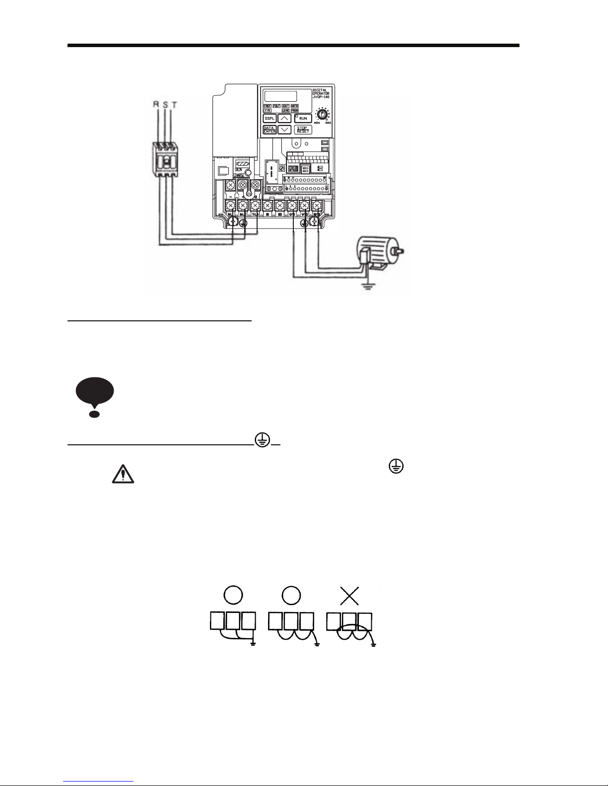
Wiring the Main Circuits
• Main Circuit Input Power Supply
Always connect the power supply line to input terminals R/L1, S/L2, and T/L3. Never connect them to terminals U/T1, V/T2, W/T3, B1, B2, −, +1, or +2. The Inverter may be damaged if the wrong terminals are connected.
For single-phase Inverters, always use terminals R/L1 and S/L2. Never connect
terminal T/L3.
• Grounding (Use ground terminal .)
Always ground the ground terminal according to the
local grounding code.
Failure to observe this warning may result in an electric
shock or a fire.
Never ground the V7AZ to the same ground as welding machines, motors, or other electrical equipment.
When several V7AZ Inverters are used side by side, ground each as shown in the following
examples. Do not loop the ground wires.
Grounding
[Example of 3-phase,
400 V Class, 0.37 kW Inverters]
MCCB or
Leakage
Breaker
L1 L2 L3
NOTE
WARNING
Good
Good
Poor
Page 36
4 Wiring
35
• Braking Resistor Connection (Optional)
To connect the braking resistor, cut the protector on terminals
B1 and B2.
To protect the braking resistor from overheating, install a thermal overload relay between the braking resistor and the
Inverter. This provides a sequence that turns OFF the power
supply with thermal relay trip contacts.
Failure to observe this warning may result in a fire.
Use this same procedure when connecting a Braking Resistor Unit.
Refer to page 223.
• Inverter Output
Connect the motor terminals to U/T1, V/T2, and W/T3.
• Wiring the Main Circuit Terminals
Pass the cables through the wiring hole to connect them. Always mount the cover in its
original position.
WARNING
Connect with a Phillips screwdriver.
Page 37
36
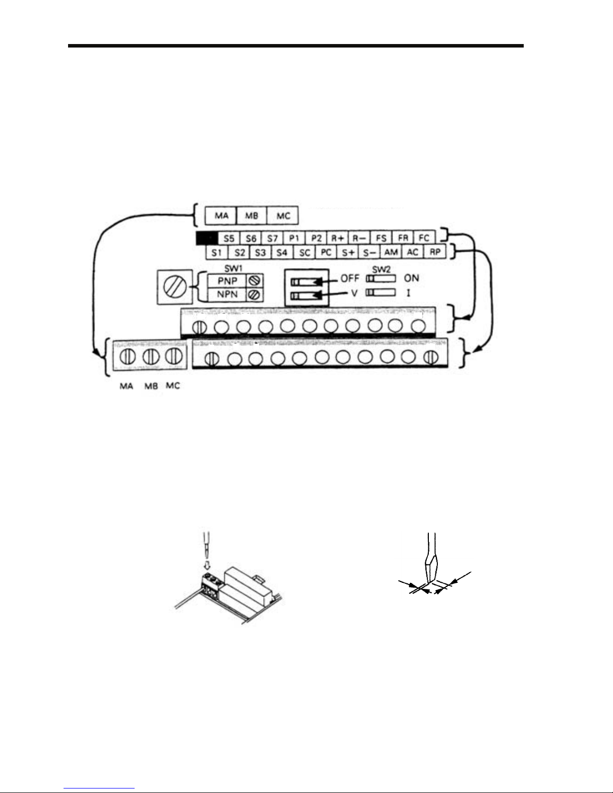
Wiring the Control Circuits
Only basic insulation is provided for the control circuit terminals.
Additional insulation may be necessary in the end product.
• Control Circuit Terminals
Pass the cable through the wiring hole to connect it. Always mount
the cover in its original position.
SW1 can be changed according to sequence input signal (S1 to S7)
polarity.
0 V common: NPN side (factory setting)
+24 V common: PNP side
Refer to pages 226 and 227 for SW1.
Refer to pages 126 and 142 for SW2.
Insert the wire into the lower part of the terminal block and connect
it tightly with a screwdriver.
Contact Output
0.4 mm max
(0.016 in.)
2.5 mm max
(0.098 in.)
Screwdriver Blade WidthWiring the Control Circuit Terminals
Page 38
4 Wiring
37
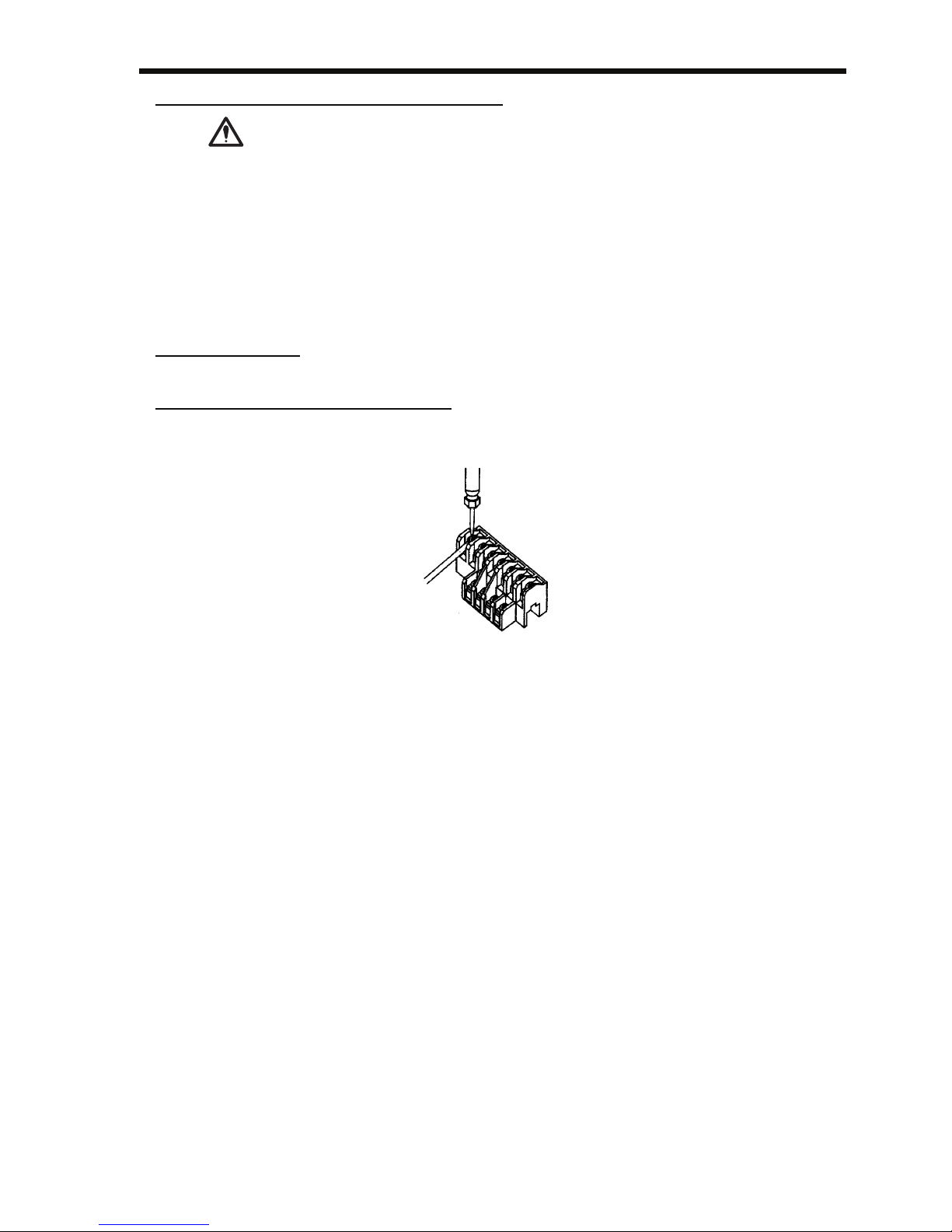
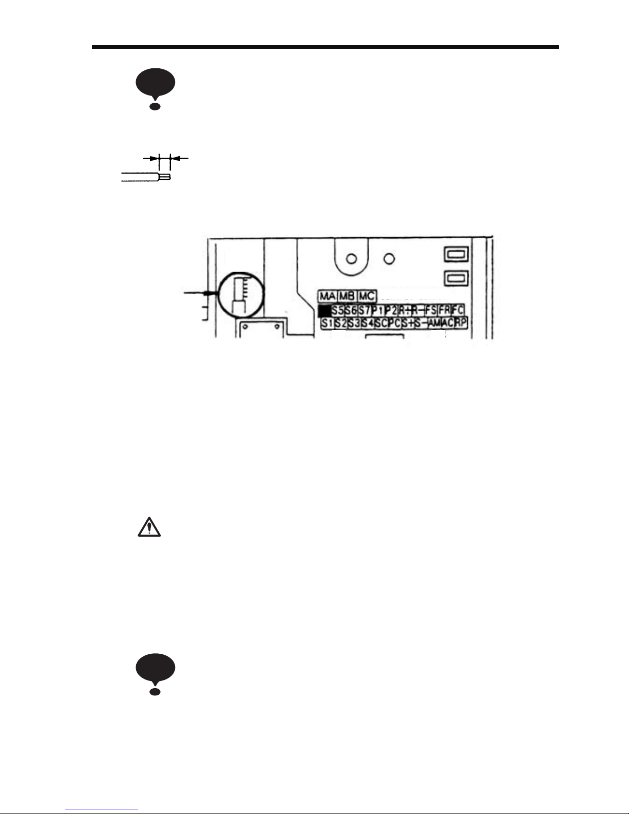
• Keep the screwdriver vertical to the Inverter.
• Refer to Page 30 for tightening torques.
Open the front cover and verify that the strip length is 5.5 mm
(0.22 in.).
Wiring Inspection
After completing wiring, check the following.
• Wiring is proper.
• Wire clippings or screws are not left in the Inverter.
• Screws are securely tightened.
• Bare wires in the terminals do not contact other terminals.
If the power supply is turned ON while the FWD (or
REV) Run Command is given, the motor will start
automatically.
Turn the power supply ON after verifying that the
RUN signal is OFF.
Failure to observe this warning may result in injury.
1. If the FWD (or REV) Run Command is given when the
Run Command from the control circuit terminal is
selected (n003 = 1), the motor will start automatically
after the main circuit input power supply is turned ON.
2. To set the 3-wire sequence, set terminal S3 (n052) to 0.
NOTE
The wire sheath strip length must be 5.5 mm (0.22 in.).
5.5 mm
(0.22 in.)
5.5mm
CONTACT OUTPUT
SW1
SW2
Scale
WARNING
NOTE
Page 39

38
5 Operating the Inverter
The Control Mode Selection (n002) is initially set to V/f control mode.
• Only turn ON the input power supply after confirming that the Digital Operator or blank cover
(optional) are in place. Do not remove the Digital
Operator or the covers while current is flowing.
Failure to observe this warning may result in an
electric shock.
• Never operate the Digital Operator or DIP switches
with wet hands.
Failure to observe this warning may result in an
electric shock.
• Never touch the terminals while current is flowing,
even if the Inverter is stopped.
Failure to observe this warning may result in an
electric shock.
• Never touch the heatsinks, which can be extremely
hot.
Failure to observe this caution may result in harmful
burns to the body.
• It is easy to change operation speed from low to
high. Verify the safe working range of the motor and
machine before operation.
Failure to observe this caution may result in injury
and machine damage.
• Install a holding brake separately if necessary.
Failure to observe this caution may result in injury.
• Do not perform signal checks during operation.
The machine or the Inverter may be damaged.
• All the constants set in the Inverter have been preset
at the factory. Do not change the settings unnecessarily.
The Inverter may be damaged.
WARNING
CAUTION
Page 40

5 Operating the Inverter
39
Test Run
The Inverter operates when a frequency (speed) is set.
There are four operating modes for the V7AZ:
1. Run Command from the Digital Operator (potentiometer/digital setting)
2. Run Command from the control circuit terminals
3. Run Command from MEMOBUS communications
4. Run Command from communication card (optional)
Prior to shipping, the Inverter is set up to receive the Run Command and
frequency reference from the Operator. Below are instructions for running the V7AZ using the JVOP-147 Digital Operator (without potentiometer). For instructions on operation, refer to page 50.
Operation reference or frequency reference constants can be selected
separately as shown below.
Name Constant
Run
Command
Selection
n003 = 0 --- Enables run, stop, and reset from Digital Operator.
= 1 --- Enables run and stop from control circuit terminals.
= 2 --- Enables MEMOBUS communications.
= 3 --- Enables communication card (optional).
Frequency
Reference
Selection
n004 = 0 --- Enables the Digital Operator’s potentiometer setting.
= 1 --- Enables Frequency Reference 1 (constant n024).
= 2 --- Enables a voltage reference (0 to 10 V) at the control circuit
terminal.
= 3 --- Enables a current reference (4 to 20 mA) at the control circuit
terminal.
= 4 --- Enables a current reference (0 to 20 mA) at the control circuit
terminal.
= 5 --- Enables a pulse train reference at the control circuit terminal.
= 6 --- Enables MEMOBUS communications.
= 7 --- Enables a voltage reference (0 to 10 V) at the Digital Operator’s
circuit terminal.
= 8 --- Enables a current reference (4 to 20 mA) at the Digital Operator’s
circuit terminal.
= 9 --- Enables communication card (optional).
Page 41
40
Operation Steps Operator
Display
Function
Indicators
Status
Indicators
1. Turn ON the power supply. 6.00
2. Set constant n004 to 1. 1
3. Set the following constants.
n019: 15.0 (acceleration time)
n020: 5.0 (deceleration time)
15.0
5.0
4. Select forward or reverse run by press-
ing or key.
Never select REV when reverse
run is prohibited.
(Forward)
or
(Reverse)
5. Set the reference by pressing or
key.
60.00
6. Press .
0.00→60.00
7. Press to stop.
If the potentiometer is switched
rapidly, the motor also accelerates or decelerates rapidly in
proportion to the potentiometer
movement. Pay attention to load
status and switch the potentiometer at the speed that will not
adversely affect motor movement.
60.00→0.00
FREF
RUN
ALARM
PRGM
RUN
ALARM
PRGM
RUN
ALARM
NOTE
F/R
RUN
ALARM
FREF
RUN
ALARM
FOUT
RUN
ALARM
NOTE
FOUT
RUN
ALARM
Status indicators : ON : Flashing (Long flashing) : Flashing : OFF
Page 42

5 Operating the Inverter
41
Selecting Rotation Direction
It is possible to select the direction in which the motor rotates when the
Forward Run Command is executed.
The motor rotates in the opposite direction when the Reverse Run Command is executed.
Operation Check Points
• Motor rotates smoothly.
• Motor rotates in the correct direction.
• Motor does not have abnormal vibration or noise.
• Acceleration and deceleration are smooth.
• Motor current consumption is matching to load condition .
• Status indicators and Digital Operator display are correct.
n040
Setting
Description
0 The motor rotates in the counterclockwise direction as
viewed from the load when the Forward Run Command is executed.
1 The motor rotates in the clockwise direction as viewed from
the load when the Forward Run Command is executed.
Page 43
42
Operating the Digital Operator
All functions of the V7AZ are set using the Digital Operator. Below are
descriptions of the display and keypad sections.
JVOP-140 Digital Operator
Data Display Section
Function Indicators
Indicators switch to another
function each time
The displayed data can
be changed.
Press to switch
between
functions.
Press to increase
constant No./data
value.
is pressed.
Operator CN2 terminal*
Press to decrease
constant No./data
value.
Status indicator
(same function as
RUN indicator)
Press to stop the motor.
(Press to reset faults.)
Press to run
the motor.
Frequency setting
potentiometer
Used to change
frequency setting.
Indicator/Display Section
(Rear side of the Operator)
CN2-1:Operator circuit terminal
(voltage reference)
CN2-2:Operator circuit terminal
(current reference)
CN2-3:GND for Operator circuit terminal
Details of Indicators (Color in parenthesis indicates the color of the indicator.)
FREF
Frequency reference
setting/monitoring
(GREEN)
F/R
Operator Run
Command FWD/REV
selection
(GREEN)
FOUT
Output frequency
monitoring
(GREEN)
IOUT
Output current
monitoring
(GREEN)
LO/RE
LOCAL/REMOTE
Selection
(RED)
MNTR
Multi-function
monitoring
(GREEN)
PRGM
Constant No./data
(RED)
Press to enter the
constant data.
(Displays the constant
data when selecting a
constant No.
for the PRGM indicator.)
* For details, refer to Operator Analog Speed Reference Block Diagram on page 167.
Page 44
5 Operating the Inverter
43
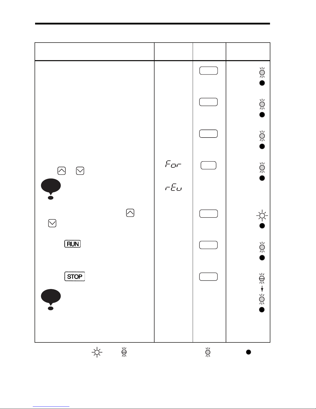
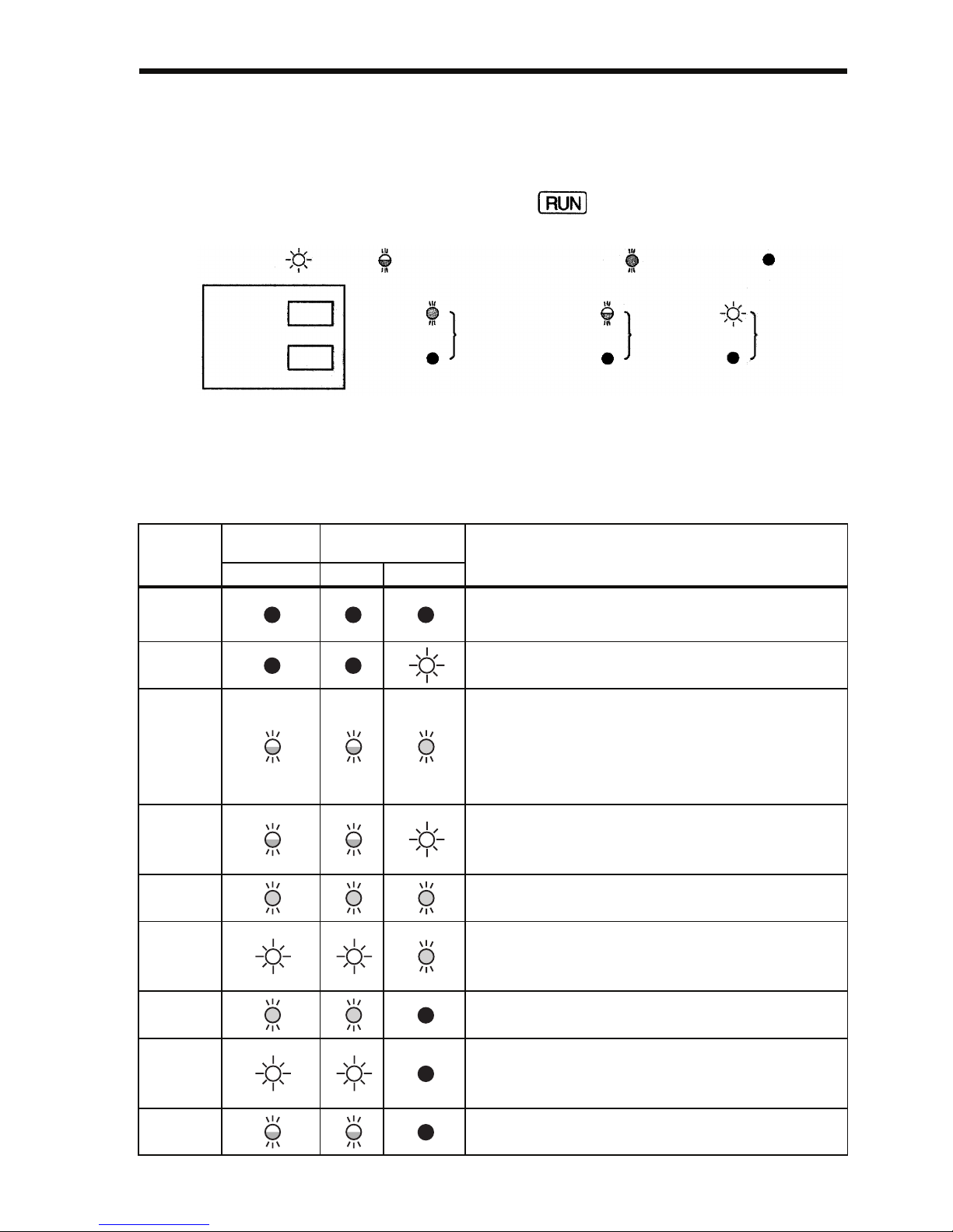
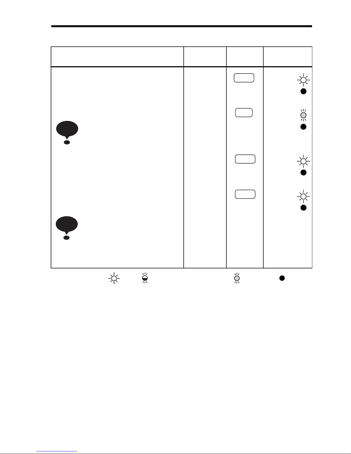
Description of Status Indicators
There are two Inverter operation status indicators on the middle right
section of the face of the V7AZ. The combinations of these indicators
indicate the status of the Inverter (ON, flashing, and OFF). The RUN
indicator and status indicator on the button have the same function.
The following table shows the relationship between the Inverter conditions and the indicator on the RUN button of the Digital Operator as
well as the RUN and ALARM indicators on the face of the V7AZ.
The indicators are lit, unlit or flashing reflecting the order of priority.
Priority
Digital
Operator
Face of
the V7AZ
Conditions
RUN RUN ALARM
1
Power supply is shut down.
Until the Inverter become ready after the power is
turned ON.
2
Fault
3
Emergency stop (Stop Command is sent from the
Digital Operator when the control circuit terminals
were used to operate the Inverter.)
Emergency stop (Emergency stop alarm is sent from
the control circuit terminal.)
Note: Indicators will be the same as with alarm
(stopped) occurring after the Inverter is stopped.
4
Emergency stop (Emergency stop fault is sent from
the control circuit terminal.)
Note: Indicators will be the same as with fault occurring after the Inverter is stopped.
5
Alarm (Stopped)
6
Alarm (Operating)
The Run Command is carried out when the External
Baseblock Command using the multi-function contact
input terminal is issued.
7
Stopped (during baseblock)
8
Operating (Including the status that the Inverter is operating at a frequency below the minimum output frequency.)
During dynamic braking when starting.
9
During deceleration to a stop
During dynamic braking when stopping.
:ON
:Flashing (long flashing) :Flashing :OFF
RUN
ALARM
(Green)
(Red)
Operation ready
(During stop)
Coast to
a stop
Normal
operation
Page 45

44
For details on how the status indicators function for Inverter faults, refer
to Chapter 8 Fault Diagnosis. If a fault occurs, the ALARM indicator
will light.
The fault can be reset by turning ON the Fault Reset signal
(or by pressing the key on the Digital Operator) with
the operation signal OFF, or by turning OFF the power supply. If the operation signal is ON, the fault cannot be reset
using the Fault Reset signal.
NOTE
Page 46
5 Operating the Inverter
45
Function Indicator Description
By pressing on the Digital Operator, each of the function indicators can be selected.
The following flowchart describes each function indicator.
Power ON
Frequency reference setting/monitoring
(Hz)
Sets V7AZ operating speed.
Output frequency monitoring (Hz)
Displays frequency that V7AZ is currently
outputting.
Setting disabled.
Output current monitoring (A)
Displays current that V7AZ is currently
outputting.
Setting disabled.
(forward run) (reverse run)
If the V7AZ loses power
while in one of these
modes, it will return to
the same mode once
power is restored.
Monitor No.
U-01: Frequency reference (FREF)
U-02: Output frequency (FOUT)
U-03: Output current (IOUT)
U-04: Output voltage reference (Unit: 1V)
U-05: DC voltage (Unit: 1V)
U-06: Input terminal status
U-07: Output terminal status
U-08: Torque monitor
U-09: Fault history (Last 4 faults)
U-10: Software number
U-11: Output power
U-13: Cumulative operation time
(5.5/7.5 kW only)
U-15: Data reception error
U-16: PID feedback
U-17: PID input
U-18: PID output
U-19: Frequency reference bias
monitor (%) (for software No.
VSP010028 or later)
FWD/REV Run selection
Sets the motor rotation direction when the RUN
command is given from the Digital Operator.
Setting can be changed using the or key.
AMulti-function monitoring
Description of the selected monitor is
displayed.
(Refer to page 48 for details.)
46
Page 47
46
If n001=5, a Run Command can be received even
while changing a constant. If sending a Run Command while changing a constant, such as during a test
run, be sure to observe all safety precautions.
Failure to observe this warning may result in injury.
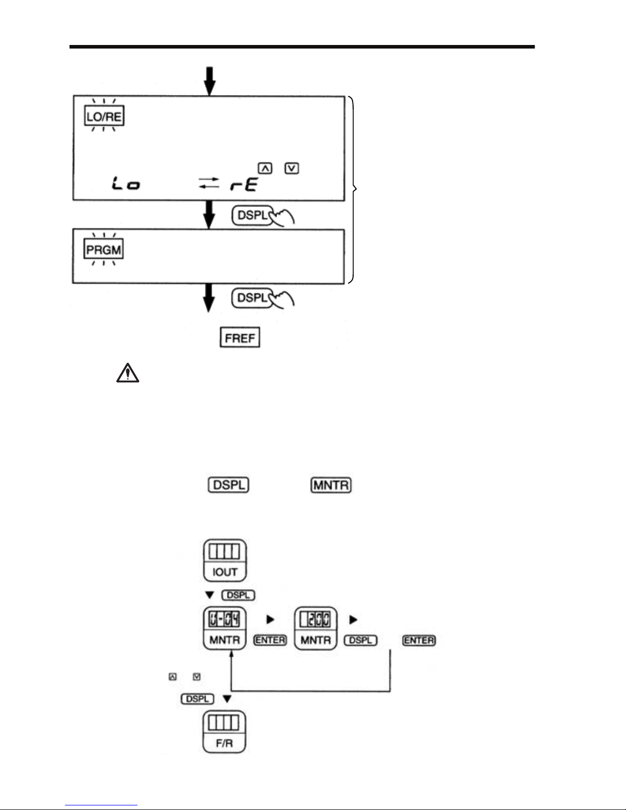
MNTR Multi-function Monitoring
Selecting the Monitor
This function switches the operation: operation
using the Digital Operator including frequency
setting with potentiometer, operation using the
input terminals, or operation through communications.
Setting can be changed using the or key.
LOCAL/REMOTE Selection
(Local)
(Remote)
Constant No./data
Sets and changes data for a constant No.
Return to
(Refer to page 49 for details.)
If the V7AZ is stopped after
it has changed to any of
these modes during operation, it changes to Program
mode from Drive mode.
Even if the Run Command
is turned ON again, the
V7AZ does not operate.
However, if n001=5, the
Run Command can be
received and the V7AZ will
operate.
WARNING
Press the key. When is ON, data
can be displayed by selecting the monitor number.
Example: Monitoring the Output Voltage Reference
Select U-04 by
pressing the
or key.
Output voltage reference
is displayed.
or
Page 48

5 Operating the Inverter
47
Monitoring
The following items can be monitored using U constants.
* 1. The status indicator is not turned ON.
* 2. Refer to the next page for input/output terminal status.
* 3. The display range is from −99.9 to 99.99 kW.
When regenerating, the output power will be displayed in units of
0.01 kW when −9.99 kW or less and in units of 0.1 kW when more
than −9.99 kW.
Con-
stant No.
Name Unit Description
U-01 Frequency Reference
(FREF)*
1
Hz Frequency reference can be monitored.
(Same as FREF)
U-02 Output Frequency
(FOUT)*
1
Hz Output frequency can be monitored.
(Same as FOUT)
U-03
Output Current (IOUT)*
1
A Output current can be monitored.
(Same as IOUT)
U-04 Output Voltage V Output voltage can be monitored.
U-05 DC Voltage V Main circuit DC voltage can be monitored.
U-06
Input Terminal Status*
2
- Input terminal status of control circuit terminals can
be monitored.
U-07
Output Terminal Status*
2
- Output terminal status of control circuit terminals can
be monitored.
U-08 Torque Monitor % The amount of output torque per rated torque of the
motor can be monitored. When V/f control mode is
selected, “---” is displayed.
U-09 Fault History
(Last 4 Faults)
- The last four fault history records are displayed.
U-10 Software No. - Software number can be checked.
U-11
Output Power*
3
kW Output power can be monitored.
U-13 Cumulative
Operation Time *
4
×10 H Cumulative operation time can be monitored in units
of 10 hours.
U-15
Data Reception Error*
5
- Contents of MEMOBUS communication data reception error can be checked.
(Contents of transmission register No. 003DH are
the same.)
U-16
PID Feedback*
6
% Input 100(%)/Max. output frequency or equivalent
U-17
PID Input*
6
% ±100(%)/± Max. output frequency
U-18
PID Output*
6
% ±100(%)/± Max. output frequency
U-19 Frequency Reference
Bias Monitor *
7
% Bias can be monitored when Up/Down Command 2
is used.
Page 49
48
In vector control mode, “---” will be displayed.
* 4. Applicable only for Inverters of 5.5 kW and 7.5 kW (200 V and 400 V
Classes).
* 5. Refer to the next page for data reception error.
* 6. Displayed in units of 0.1% when less than 100% and in units of 1% when
100% or more. The display range is from −999% to 999%.
* 7. Applicable for Inverters with software version VSP0105740(4.0kW or
less) and VSP015750(5.5kW and 7.5kW).
Input/Output Terminal Status
Data Reception Error Display
1: Terminal S1 is closed.
1: Terminal S2 is closed.
1: Terminal S3 is closed.
1: Terminal S4 is closed.
1: Terminal S5 is closed.
1: Terminal S6 is closed.
1: Terminal S7 is closed.
Not used
Input Terminal Status
1: Terminal MA-MC is closed.
1: Terminal P1-PC is closed.
1: Terminal P2-PC is closed.
Not used
Output Terminal Status
1: CRC error
1: Data length error
Not used
1: Parity error
1: Over run error
1: Framing error
1: Timeover
Not used
Page 50
5 Operating the Inverter
49
Fault History Display Method
When U-09 is selected, a four-digit box is displayed. The three digits
from the right show the fault description, and the digit on the left shows
the order of fault (from one to four). Number 1 represents the most
recent fault, and numbers 2, 3, 4 represent the other faults, in ascending
order of fault occurrence.
Example:
yyyyyy 4-digit number
: Order of fault (1 to 4)
: Fault description
"---" is displayed if there is no fault.
(Refer to Chapter 8 Fault Diagnosis for details.)
Switching Fault History Records
The fault that is displayed can be changed using the or key.
Clearing the Fault History
Set constant n001 to 6 to clear the fault history. The display will return
to n001 after 6 is set.
Note: Initializing the constants (n001=12, 13) also clears the fault history.
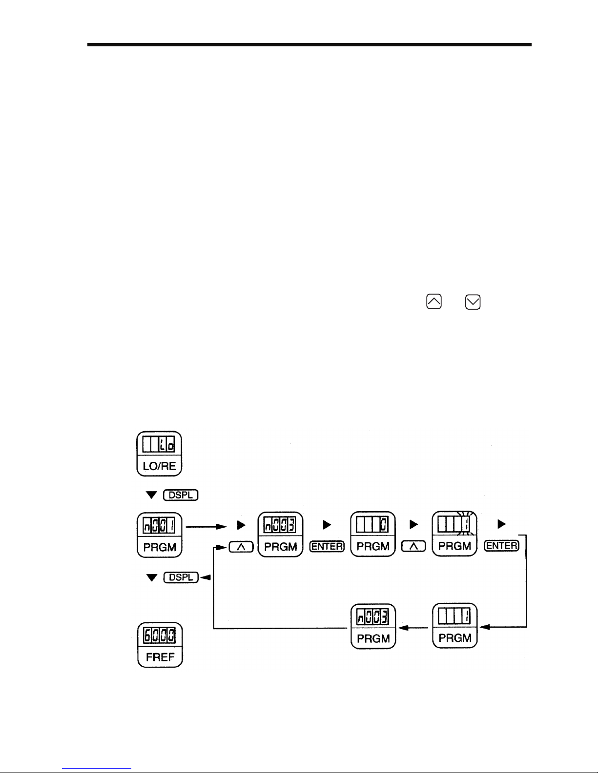
Setting and Referencing Constants
The following diagram shows how to select and change constants.
REMOTE/LOCAL
selection
Constant
No./
data
n003
Operation
reference
selection
Factory setting: 0
Operator reference
Set to 1
Control circuit
terminal reference
(flashing when changing)
Data set
Return to
constant No.
display after
1 second
• Setting n003 (Run Command selection)
Page 51

50
Simple Data Setting
Digital setting (refer to 5 Operating the Inverter) and potentiometer set-
ting are both possible for simple acceleration/deceleration operation of
the V7AZ.
Digital setting is set at the factory (n004=1). For the model with JVOP140 Digital Operator (with potentiometer), factory setting is set by a frequency-setting potentiometer (n004=0).
Following is an example in which the function indicators are used to set
frequency reference, acceleration time, deceleration time, and motor
direction.
Page 52
5 Operating the Inverter
51
Data Setting by Frequency-setting Potentiometer
Operation Steps Operator
Display
Function
Indicators
Status
Indicators
1. Turn the potentiometer fully to the left.
Then, turn the power ON.
0.00
2. F/R flashes.
Select FWD/REV Run using keys.
Never select REV when reverse
run is prohibited.
FOR
or
REV
3. Press DSPL to flash FREF. Then press
RUN.
0.00
4. Operate the motor by turning the potentiometer to the right. (Frequency reference corresponding to the
potentiometer position is displayed.)
If the potentiometer is switched
rapidly, the motor also accelerates or decelerates rapidly corresponding to the potentiometer
movement. Pay attention to load
status and switch the potentiometer at a speed that does not
affect motor movement.
0.00 to
60.00
Minimum
output
frequency is
1.50 Hz
FREF
RUN
ALARM
NOTE
F/R
RUN
ALARM
FREF
RUN
ALARM
NOTE
FREF
RUN
ALARM
Status indicators : ON : Flashing (Long flashing) : Flashing : OFF
Page 53

52
6 Programming Features
Factory settings of the constants are shaded in the tables.After wiring is
complete, be sure to make the following settings before operation.
Hardware
Make the following settings before the Inverter is turned ON.
Software (Constant)
Item Ref.
page
Sequence input signal (S1 to S7) polarity selection 226
Voltage reference / current reference input selection of control circuit terminal FR
126
Item Ref.
page
Environment
setting
Constant Selection / Initialization (n001) 53
Control Mode Selection (n002) 59
Run Command Selection (n003) 63
Frequency Reference Selection (n004) 64
Stopping Method Selection (n005) 106
Basic
characteristics
and frequency reference setting
V/f pattern setting (n011 to n017) 55
Acceleration Time 1 (n019),
Deceleration Time 1 (n020)
77
Frequency Reference 1 to 8
(n024 to n031)
74
Motor protection Motor Rated Current (n036) 136
Electric Thermal Motor Protection
Selection (n037)
136
Countermeasure
for noise and leakage current
Carrier Frequency Reference (n080) 94
Using an optional
braking resistor
Stall Prevention during Deceleration
(n092)
134
Page 54
6 Programming Features
53
Constant Setup and Initialization
Constant Selection/Initialization (n001)
If n001=5, a Run Command can be received even
while changing a constant. If sending a Run Command while changing a constant, such as during a test
run, be sure to observe all safety precautions.
Failure to observe this warning may result in injury.
The following table lists the data that can be set or read when n001 is
set. By setting this constant, the fault history can be cleared and the constants initialized. Unused constants between n001 and n179 are not displayed.
* 1. Excluding setting-disabled constants.
* 2. Refer to page 112.
appears on the display for one second and the set data
returns to its initial values in the following cases.
1. If the set values of Multi-function Input Selections 1 to 7
n001
Setting
Constant That Can Be Set Constant That Can Be Referenced
0 n001 n001 to n179
1
n001 to n049
*1
2
n001 to n079
*1
3
n001 to n119
*1
4
n001 to n179
*1
5
n001 to n179
*1
(Run Command can be received in Program mode.)
6 Fault history cleared
7 to 11 Not used
12 Initialize
13
Initialize (3-wire sequence)
*2
WARNING
NOTE
Page 55

54
(n050 to n056) are the same
2. If the following conditions are not satisfied in the V/f pattern setting:
Max. Output Frequency (n011) ≥ Max. Voltage Output
Frequency (n013)
> Mid. Output Frequency
(n014)
≥ Min. Output Frequency
(n016)
Note: Mid. Output Frequency (n014) is also used for
motor 2 settings, n014 has to be lower than n140 and
n147.
For details, refer to Adjusting Torque According to Appli-
cation (V/f Pattern Setting) on page 55.
3. If the following conditions are not satisfied in the jump
frequency settings:
Jump Frequency 3 (n085) ≤ Jump Frequency 2 (n084)
≤ Jump Frequency 1 (n083)
4. If the Frequency Reference Lower Limit (n034) ≤ Fre-
quency Reference Upper Limit (n033)
5. If the Motor Rated Current (n036) ≤ 150% of Inverter
rated current
6. If one of the Acceleration/Deceleration Time settings
(n019 to n022) exceeds 600.0 sec. and it is tried to set
n018 to 1 (Acceleration/Deceleration Time Unit 0.01 sec).
Page 56
6 Programming Features
55
Using V/f Control Mode
V/f control mode is preset at the factory.
Control Mode Selection (n002) = 0: V/f control mode (factory setting)
1: Vector control mode
Adjusting Torque According to Application
Adjust motor torque by using the V/f pattern and full-range automatic
torque boost settings.
V/f Pattern Setting
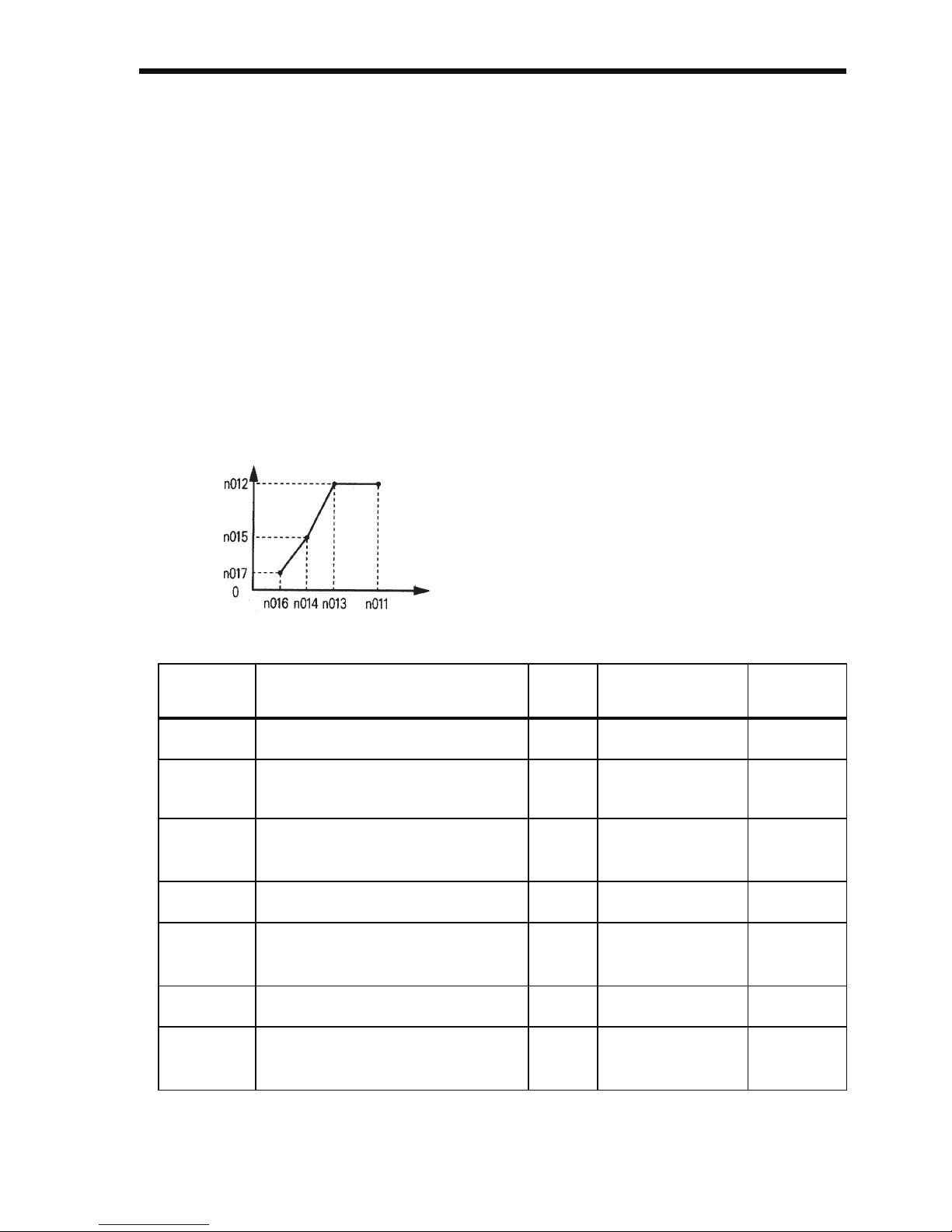
Set the V/f pattern in n011 to n017 as described below. Set each pattern
when using a special motor (e.g., high-speed motor) or when requiring
special torque adjustment of the machine.
Note: The values in the parentheses are for the 400 V Class of Inverters.
Constant
No.
Name Unit Setting Range Factory
Setting
n011
Max. Output Frequency
0.1 Hz 50.0 to 400.0 Hz 50.0 Hz
n012
Max. Voltage
0.1 V
0.1 to 255.0 V
(0.1 to 510.0 V)
200.0 V
(400.0 V)
n013
Max. Voltage Output Frequency (Base Frequency)
0.1 Hz 0.2 to 400.0 Hz 50.0 Hz
n014
Mid. Output Frequency
0.1 Hz 0.1 to 399.9 Hz 1.3 Hz
n015
Mid. Output Frequency
Voltage
0.1 V
0.1 to 255.0 V
(0.1 to 510.0 V)
12.0 V*
(24.0 V)
n016
Min. Output Frequency
0.1 Hz 0.1 to 10.0 Hz 1.3 Hz
n017
Min. Output Frequency
Voltage
0.1 V 0.1 to 50.0 V
(0.1 to 100.0 V)
12.0 V*
(24.0 V)
Be sure to satisfy the following
conditions for the settings of n011 to
n017.
n016 ≤ n014 < n013 ≤ n011
If n016 = n014, the setting of n015
will be disabled.
Note: n014 is also used for motor 2
settings. (n014 < n140, n147)
f
(Frequency)
V: (Voltage)
Page 57

56
* 10.0 V (20.0 V) for Inverters of 5.5 kW and 7.5 kW (200 V and 400 V
Classes).
Page 58
6 Programming Features
57
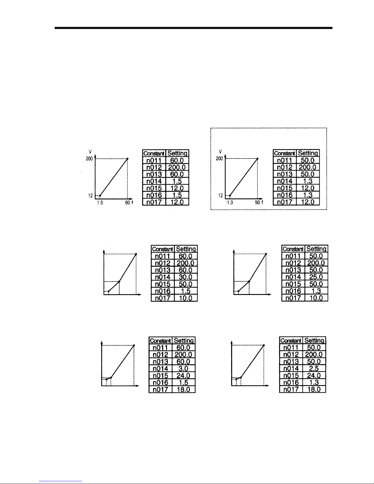
Typical Setting of the V/f Pattern
Set the V/f pattern according to the application as described below. For
400-V Class Inverters, the voltage values (n012, n015, and n017)
should be doubled. When running at a frequency exceeding 50/60 Hz,
change the Maximum Output Frequency (n011).
Note: Always set the maximum output frequency according to the motor char-
acteristics.
1. For General-purpose Applications
2. For Fans/Pumps
3. For Applications Requiring High Starting Torque
Increasing the voltage of the V/f pattern increases motor torque, but
an excessive increase may cause motor overexcitation, motor overheating, or vibration.
Note: Constant n012 must be set to motor rated voltage.
Motor Specification: 60 Hz
Motor Specification: 50 Hz
(Factory setting)
Motor Specification: 60 Hz Motor Specification: 50 Hz
10
1.5 30 60 f
50
200
V
10
1.3 25 50 f
50
200
V
Motor Specification: 60 Hz Motor Specification: 50 Hz
18
1.5
360f
24
200
V
18
1.3 2.5
50 f
24
200
V
Page 59
58
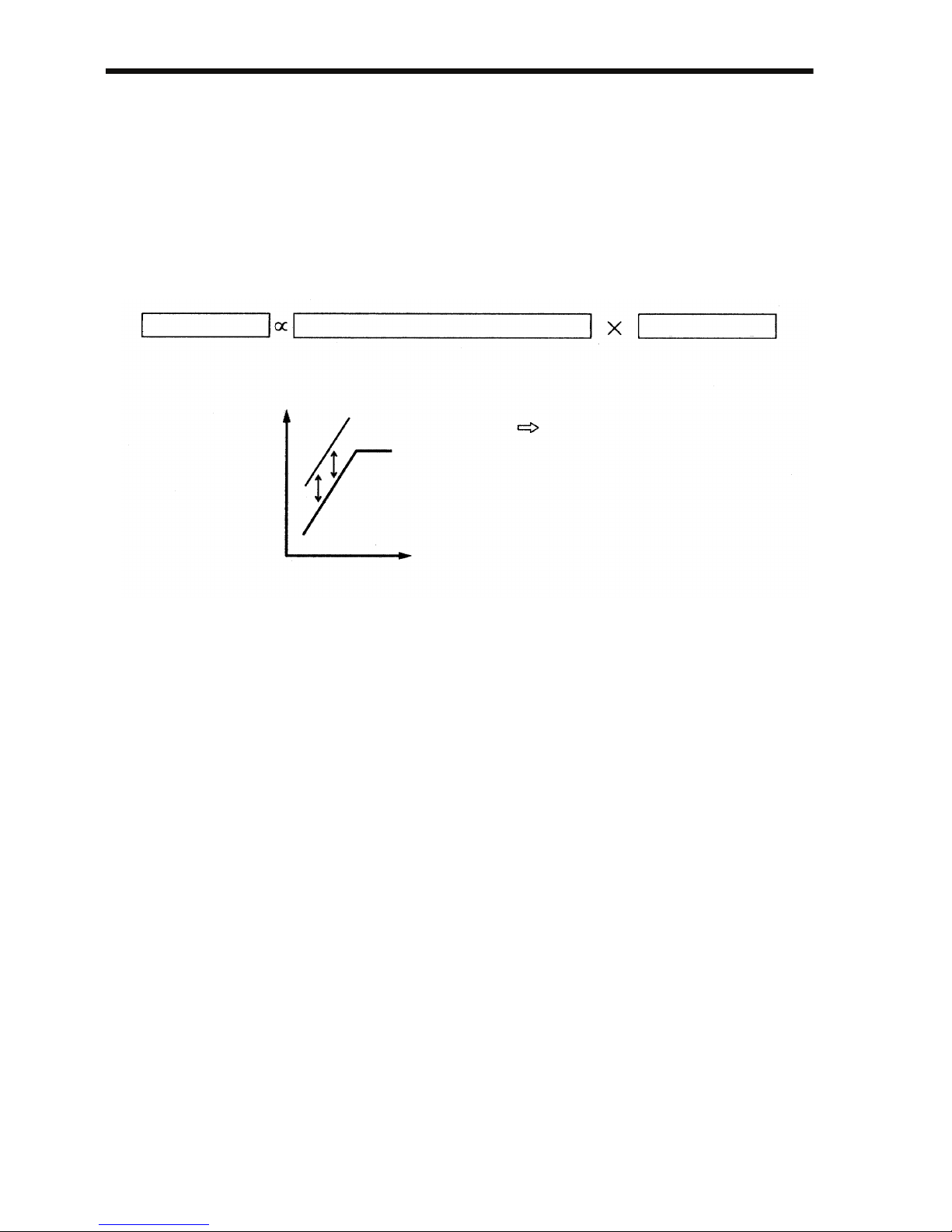
Full-range Automatic Torque Boost (when V/f Mode is
Selected: n002=0)
The motor torque requirement changes according to load conditions.
The full-range automatic torque boost adjusts the voltage of the V/f pattern according to requirements. The V7AZ automatically adjusts the
voltage during constant-speed operation, as well as during acceleration.
The required torque is calculated by the Inverter.
This ensures tripless operation and energy-saving effects.
Normally, no adjustment is necessary for the Torque Compensation
Gain (n103, factory setting: 1.0). When the wiring distance between the
Inverter and the motor is long, or when the motor generates vibration,
change the automatic torque boost gain. In these cases, set the V/f pattern (n011 to n017).
Adjustment of the Torque Compensation Time Constant (n104) and the
Torque Compensation Iron Loss (n105) are normally not required.
Adjust the torque compensation time constant under the following conditions:
• Increase the setting if the motor generates vibration.
• Reduce the setting if response is slow.
Output voltage Torque Compensation Gain (n103) Required torque
Required torque
Increase voltage
V
(Voltage)
f (Frequency)
Operation
Page 60

6 Programming Features
59
Using Vector Control Mode
Set the Control Mode Selection (n002) to use vector control mode.
n002 = 0: V/f control mode (factory setting)
1: Vector control mode
Precautions for Voltage Vector Control Application
Vector control requires motor constants. The factory settings constants
have been set at the factory prior to shipment. Therefore, when a motor
designed for an Inverter is used or when a motor from any other manufacturer is driven, the required torque characteristics or speed control
characteristics may not be maintained because the constants are not suitable. Set the following constants so that they match the required motor
constants.
* Setting depends on Inverter capacity. (Refer to pages 245 and 246.)
Adjustment of the Torque Compensation Gain (n103) and the Torque
Compensation Time Constant (n104) is normally not required.
Adjust the torque compensation time constant under the following conditions:
• Increase the setting if the motor generates vibration.
• Reduce the setting if response is slow.
Adjust the Slip Compensation Gain (n111) while driving the load so
that the target speed is reached. Increase or decrease the setting in increments of 0.1.
Constant
No.
Name Unit Setting
Range
Factory
Setting
n106
Motor Rated Slip
0.1 Hz 0.0 to
20.0 Hz
*
n107
Motor Line-toneutral Resistance
0.001 Ω
(less than 10 Ω)
0.01 Ω
(10 Ω or more)
0.000 to
65.50 Ω
*
n036
Motor Rated Current
0.1 A 0% to 150%
of Inverter
rated current
*
n110
Motor No-load
Current
1% 0% to 99%
(100% =
motor rated
current)
*
Page 61
60
• If the speed is less than the target value, increase the slip compensation gain.
• If the speed is more than the target value, reduce the slip compensation gain.
Adjustment of the Slip Compensation Time Constant (n112) is normally
not required. Adjust it under the following conditions:
• Reduce the setting if response is slow.
• Increase the setting if speed is unstable.
Select slip compensation status during regeneration as follows:
Motor Constant Calculation
An example of motor constant calculation is shown below.
1. Motor Rated Slip (n106)
2. Motor Line-to-neutral Resistance (n107)
Calculations are based on the line-to-line resistance and insulation
grade of the motor test report.
3. Motor Rated Current (n036)
= Rated current at motor rated frequency (Hz)*1 (A)
4. Motor No-load Current (n110)
* 1. Base frequency (Hz) during constant output control
* 2. Rated speed (rpm) at base frequency during constant output control
n113 Setting Slip Correction during Regenerative Operation
0 Disabled
1 Enabled
120 × Motor rated frequency (Hz)*
1
Number of motor poles
Motor rated speed (min
-1
)*
2
120/Number of motor poles
E type insulation: Test report of line-to-line resistance at 75°C (Ω) × 0.92 ×
B type insulation: Test report of line-to-line resistance at 75°C (Ω) × 0.92 ×
F type insulation: Test report of line-to-line resistance at 115°C (Ω) × 0.87 ×
No-load current (A) at motor rated frequency (Hz)*
1
Rated current (A) at motor rated frequency (Hz)*
1
100 (%)
Page 62
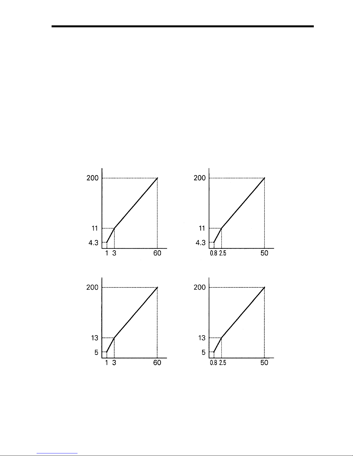
6 Programming Features
61
Set n106 (Motor Rated Slip), n036 (Motor Rated Current), n107 (Motor
Line-to-neutral Resistance), and n110 (Motor No-load Current) according to the motor test report.
To connect a reactor between the Inverter and the motor, set n108 to the
sum of the initial value of n108 (Motor Leakage Inductance) and the
externally mounted reactor inductance. Unless a reactor is connected,
n108 (Motor Leakage Inductance) does not have to be set according to
the motor.
V/f Pattern during Vector Control
Set the V/f pattern as follows during vector control:
The following examples are for 200 V Class motors. When using 400 V
Class motors, double the voltage settings (n012, n015, and n017).
Standard V/f
[Motor Specification: 60 Hz]
(V)
(Hz)
[Motor Specification: 50 Hz]
(V)
(Hz)
[Motor Specification: 50 Hz]
(V)
(Hz)
High Starting Torque V/f
[Motor Specification: 60 Hz]
(V)
(Hz)
Page 63
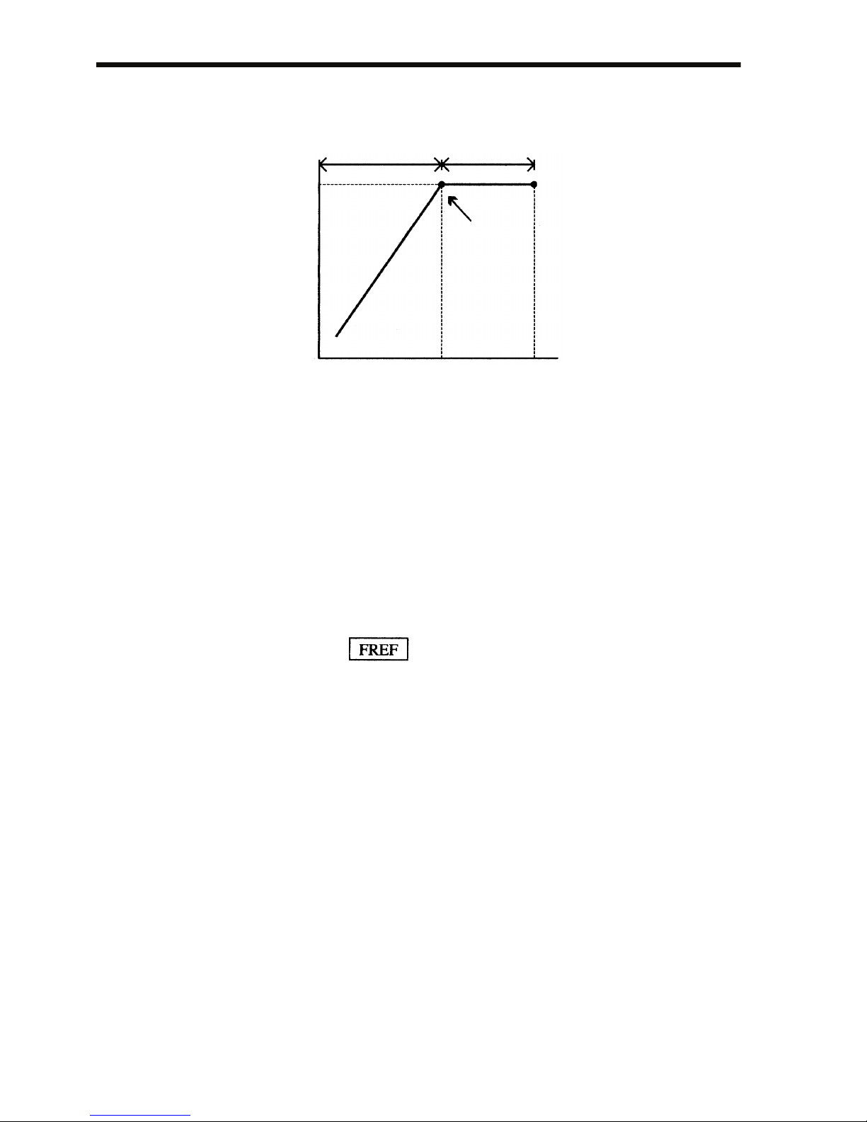
62
When operating with a frequency larger than 60/50 Hz, change only the
Max. Output Frequency (n011).
Switching LOCAL/REMOTE Mode
The following functions can be selected by switching LOCAL or
REMOTE mode. To select the Run/Stop Command or frequency reference, change the mode in advance depending on the following applications.
• LOCAL mode: Enables the Digital Operator for Run/Stop Com-
mands and FWD/REV Run Commands. The frequency reference can be set using the potentiometer
or .
• REMOTE mode: Enables Run Command Selection (n003).
The frequency reference can be set using the Frequency Reference Selection (n004).
Constant torque
Constant output or
variable output
Base point
n013
=60 or 50 Hz
n011
=90 Hz
012
200 V
Page 64
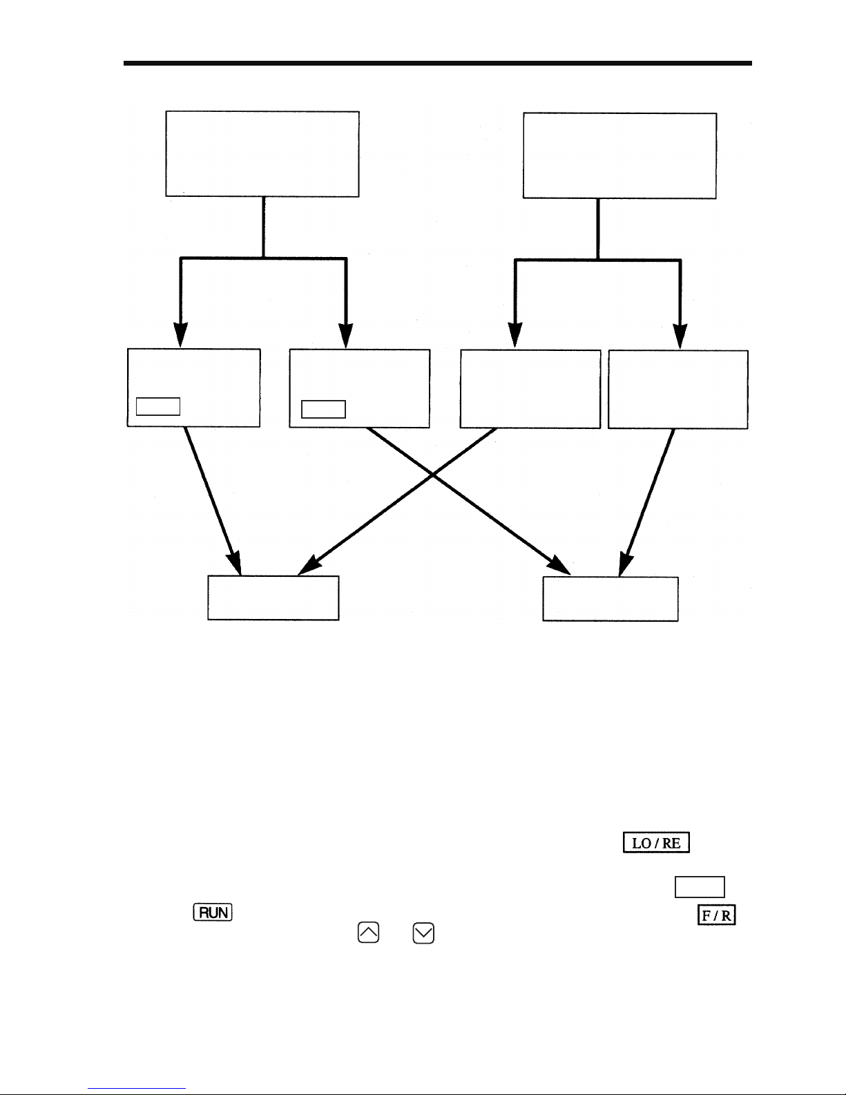
6 Programming Features
63
How to Select LOCAL/REMOTE Mode
Selecting Run/Stop Commands
Refer to Switching LOCAL/REMOTE Mode (page 62) to select either
the LOCAL mode or REMOTE mode.
The operation method (Run/Stop Commands, FWD/REV Run Commands) can be selected using the following method.
LOCAL Mode
When Lo (local mode) is selected for Digital Operator ON
mode, or when the LOCAL/REMOTE switching function is set and the
input terminals are turned ON, run operation is enabled by the or
on the Digital Operator, and FWD/REV is enabled by the
ON mode (using the or key).
When LOCAL/REMOTE
switching function is not
set for multi-function
input selection
(When 17 is not set
for any of constants
n050 to n056)
Select Lo for
operator
LO/RE
selection.
Select rE for
operator
LO/RE
selection.
When LOCAL/REMOTE
switching function is set
for multi-function input
selection
(When 17 is set for
any of constants
n050 to n056)
Turn ON multifunction input
terminal.
Turn OFF multifunction input
terminal.
REMOTE mode
LOCAL mode
STOP
Page 65
64
REMOTE Mode
1. Select REMOTE mode.
The following two methods can be used to select REMOTE mode.
• Select rE (REMOTE mode) for the selection.
• When the LOCAL/REMOTE switching function is selected for
the multi-function input selection, turn OFF the input terminal to
select REMOTE mode.
2. Select the operation method by setting constant n003.
n003=0: Enables the Digital Operator (same with LOCAL mode).
=1: Enables the multi-function input terminal (see fig. below).
=2: Enables communications (refer to page 141).
=3: Enables communication card (optional).
• Example when using the multi-function input terminal as operation reference (two-wire sequence)
• For an example of three-wire sequence, refer to page 112.
• For more information on how to select the sequence polarity, refer
to page 226.
Note: When the Inverter is operated without the Digital Operator, always set
constant n010 to 0.
n010 = 0: Detects fault contact of the Digital Operator (factory setting)
= 1: Does not detect fault contact of the Digital Operator
Operating (Run/Stop Commands) by Communications
Setting constant n003 to 2 in REMOTE mode enables using Run/Stop
commands via MEMOBUS communications. For commands using
communications, refer to page 141.
Selecting Frequency Reference
Select REMOTE or LOCAL mode in advance. For the method for
selecting the mode, refer to page 63.
FWD Run/Stop
REV Run/Stop
n003: 1 (Factory setting: 0)
n050: 1 (Factory setting)
n051: 2 (Factory setting)
Page 66
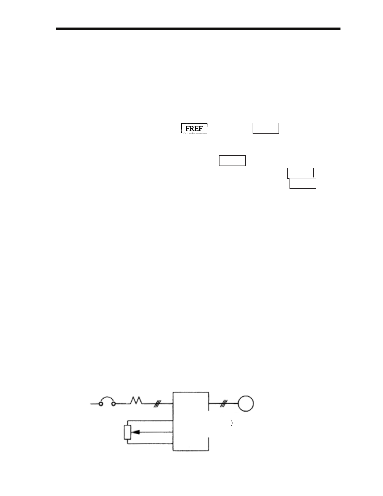
6 Programming Features
65
LOCAL Mode
Select the command method using constant n008.
n008=0: Enables using the potentiometer on the Digital Operator.
=1: Enables digital setting on the Digital Operator
(factory setting).
The factory setting for models with the Digital Operator
with a potentiometer (JVOP-140) is n008=0.
• Digital Setting Using the Digital Operator
Input the frequency while is lit (press after setting the
numeric value).
Frequency reference setting is effective when 1 (factory setting: 0) is set
for constant n009 instead of pressing .
n009 =0: Enables frequency reference setting using the key.
=1: Disables frequency reference setting using the key.
REMOTE Mode
Select the command method in constant n004.
n004 =0: Enables frequency reference setting using the potentiometer
on the Digital Operator.
=1: Enables using frequency reference 1 (n024) (factory setting)
Factory setting of models with the Digital Operator with
a potentiometer (JVOP-140) is n004=0.
=2: Enables a voltage reference (0 to 10 V) (refer to the figure
on page 65).
=3: Enables a current reference (4 to 20 mA) (refer to page 126).
=4: Enables a current reference (0 to 20 mA) (refer to page 126).
=5: Enables a pulse train reference (refer to page 128).
=6: Enables communication (refer to page 141).
=7: Enables a voltage reference on Digital Operator circuit
terminal CN2 (0 to 10 V)
=8: Enables a current reference on Digital Operator circuit
terminal CN2 (4 to 20 mA)
=9: Enables communication card (optional).
Example of frequency reference by voltage signal
ENTER
ENTER
ENTER
ENTER
IM
2 kΩ
(0 to +10 V)
FS
FR (Master Frequency Reference)
FC (0 V)
n004=2
(factory setting: 1)
(Frequency Setting Power
+12 V 20 mA
Master
Frequency
Reference
Page 67
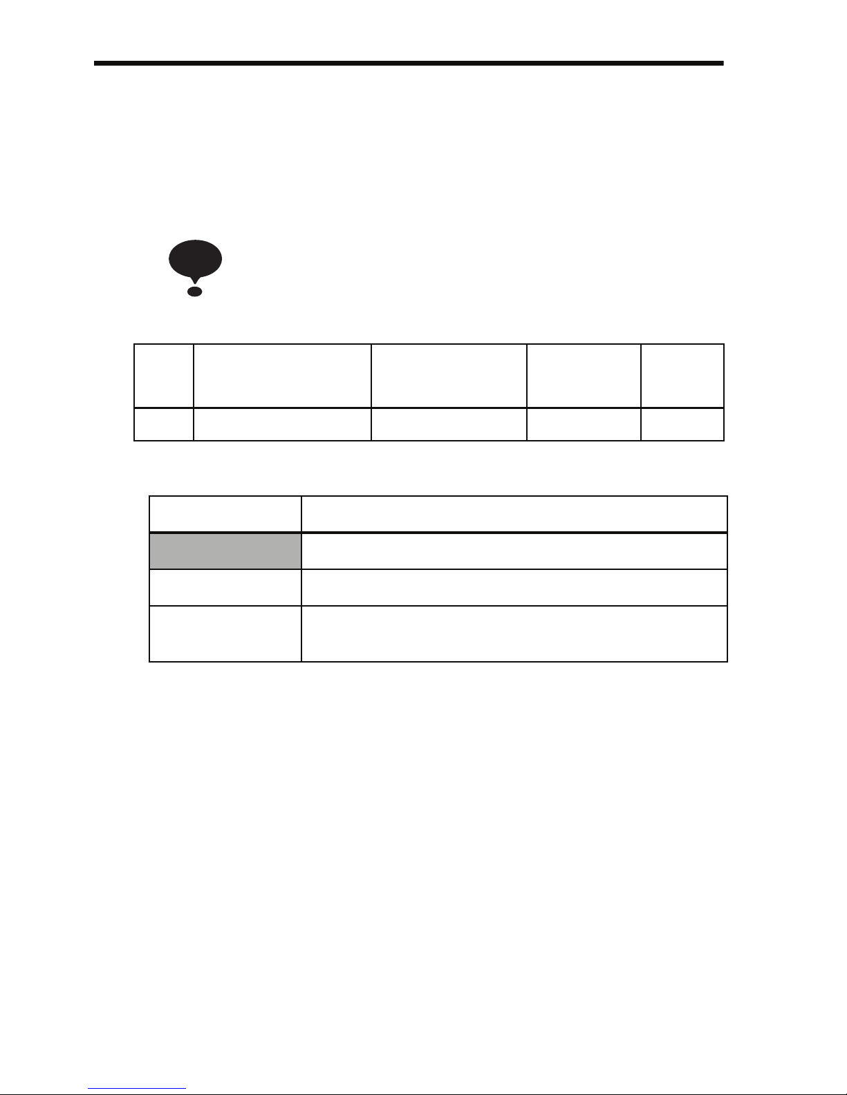
66
Setting Operation Conditions
Autotuning Selection (n139)
Motor data required for vector control can be measured and set by
inputting the data from the nameplate of the motor to be used and performing autotuning for the motor. Autotuning is possible only for motor
1.
Autotuning mode cannot be entered when motor 2 is selected
using a Motor Switching Command allocated to a multi-function input (i.e., Autotuning Selection (n139) setting is not
possible).
n139 Settings
Note: Setting is not possible when motor 2 is selected using a Motor Switching
Command allocated to a multi-function input. ("Err" will be displayed
on the Digital Operator, and the setting will return to the value before the
change.)
Use the following procedure to perform autotuning to automatically set
motor constants when using the V/f control method, when the cable
length is long, etc.
Setting the Autotuning Mode
One of the following two autotuning modes can be set.
• Rotational autotuning
• Stationary autotuning for motor line-to-neutral resistance only
Always confirm the precautions before autotuning.
Constant
No.
Name Unit Setting
Range
Factory
Setting
n139 Autotuning Selection − 0 to 2 0
Setting Function
0 Disabled
1 Rotational autotuning (motor 1)
2 Stationary autotuning for motor line-to-neutral
resistance only (motor 1)
NOTE
Page 68

6 Programming Features
67
• Rotational Autotuning (n139 = 1)
Rotational autotuning is used only for open-vector control. Set n139 to
1, input the data from the nameplate, and then press the RUN key on the
Digital Operator. The Inverter will stop the motor for approximately
1 minute and then set the required motor constants automatically while
operating the motor for approximately 1 minute.
1. When performing rotational autotuning, be sure to separate the motor from the machine and first confirm that it is
safe for the motor to rotate.
2. For a machine in which the motor itself cannot be rotated,
set the values from the motor test report.
3. If automatic rotation poses no problem, perform rotational
autotuning to ensure performance.
• Stationary Autotuning for Motor Line-to-neutral Resistance
Only (n139 = 2)
Autotuning can be used to prevent control errors when the motor cable
is long or the cable length has changed since installation or when the
motor and Inverter have different capacities.
Set n139 to 2 for open-loop vector control, and then press the RUN key
on the Digital Operator. The Inverter will supply power to the stationary
motor for approximately 20 seconds and the Motor Line-to-neutral
Resistance (n107) and cable resistance will be automatically measured.
1. Power will be supplied to the motor when stationary autotuning for motor line-to-neutral resistance only is performed even though the motor will not turn. Do not touch
the motor until autotuning has been completed.
2. When performing stationary autotuning for motor line-toneutral resistance only connected to a conveyor or other
machine, ensure that the holding brake is not activated
during autotuning.
Precautions before Using Autotuning
Read the following precautions before using autotuning.
• Autotuning the Inverter is fundamentally different from autotuning
the servo system. Inverter autotuning automatically adjusts parameters according to detected motor constants, whereas servo system
autotuning adjusts parameters according to the detected size of the
load.
NOTE
NOTE
Page 69

68
• When speed precision is required at high speeds (i.e., 90% of the
rated speed or higher), use a motor with a rated voltage that is 20 V
less than the input power supply voltage of the Inverter for 200Vclass Inverters and 40 V less for 400V-class Inverters. If the rated
voltage of the motor is the same as the input power supply voltage,
the voltage output from the Inverter will be unstable at high speeds
and sufficient performance will not be possible.
• Use stationary autotuning for motor line-to-neutral resistance only
whenever performing autotuning for a motor that is connected to a
load. (To ensure performance, set the value from the motor test
report.)
• Use rotational autotuning if performing autotuning is possible while
not connected to a load.
• If rotational autotuning is performed for a motor connected to a load,
the motor constants will not be found accurately and the motor may
exhibit abnormal operation. Never perform rotational autotuning for
a motor connected to a load.
• The status of the multi-function inputs and multi-function outputs
will be as shown in the following table during autotuning. When performing autotuning with the motor connected to a load, be sure that
the holding brake is not applied during autotuning, especially for
conveyor systems or similar equipment.
• To cancel autotuning, always use the key on the Digital
Operator.
Precautions for Using Autotuning(when motor voltage > supply
voltage)
Use the following procedure to perform autotuning if using a motor with a rated voltage
higher than the Inverter input power supply.
1. Input the rated voltage from the motor nameplate for the Maximum Voltage (n012).
2. Set the Maximum Voltage Output Frequency (n013) to the base frequency on the
motor nameplate.
3. Perform autotuning.
4. Record the Motor No-load Current (n110).
Tuning Mode Multi-function Inputs Multi-function Outputs
Rotational autotuning Do not function. Same as during nor-
mal operation
Stationary autotuning
for motor line-to-neu-
tral resistance only
Do not function. Maintain same status
as when autotuning is
started.
STOP
DSPL
PRGM
Page 70

6 Programming Features
69
5. Calculate the rated secondary current of the motor using the following equation:
6. Input the power supply voltage for the Maximum Voltage (n012).
7. Input the following calculated value for the Maximum Voltage Output
Frequency (n013):
8. Perform autotuning again.
9. Record the Motor No-load Current (n110) again.
10. Calculate the rated secondary current of the motor using the following equation:
11. Input the following calculated value for the Motor Rated Slip (n106):
1. When speed precision is required at high speeds (i.e., 90% of the rated
speed or higher), set n012 (Max. Voltage) to the input power supply
voltage × 0.9.
2. When operating at high speeds (i.e., 90% of the rated speed or higher), the
output current will increase as the input power supply voltage is reduced.
Be sure to provide sufficient margin in the Inverter current.
Operating Procedure
1. Confirm the following:
• The motor is separated from the machine system.
• The motor shaft lock key is removed.
• If there is a brake, it is released.
• The wiring is correct.
2. The Inverter power supply is ON.
3. There is no error.
4. Select Program Mode by pressing until is lit.
5. Set the following constants for the selected motor to the nameplate
ated Secondary Current Rated Current()
2
No-Load Current()
2
–=
Maximum Voltage Output Frequency
Base Frequency on the Motor Nameplate Power Supply Voltage×
Rated Voltage on the Motor Namplate
---------------------------------------------------------------------------------------------------------------------------------------------------------------
=
Rated Secondary Current
Rated Secondary Current calculated in Step 5 Rated Voltage on Motor Nameplate×
Power Supply Voltage
---------------------------------------------------------------------------------------------------------------------------------------------------------------------------------------------------------
=
Motor Rated Slip
Base Freq. from Motor Nameplate Rated Speed from Motor Nameplate
Number of Poles
120
----------------------------------------
×–
⎝ ⎠
⎛ ⎞
No-Load Current in Step 9
No-Load Current in Step 4
Rated Secondary Current in Step 5
-----------------------------------------------------------------------------------
×
-------------------------------------------------------------------------------------------------------------------------------------------------------------------------------------------------------------------------------------
=
NOTE
Page 71
70
values.
When performing precision setting (i.e., when performing autotuning using a motor test report or design data), the input data to set
when autotuning will differ. Refer to the table below.
6. Set the Autotuning Selection (n139).
7. Press the key to select the autotuning mode.
• The Digital Operator will display "TUn." The shows the
autotuning method selected for n139.
• All function indicators will turn OFF.
• The status indicators will return to operation ready status.
• Only the , , and keys will be accepted in
autotuning mode.
• Autotuning will start when the key is input.
• Autotuning will be cancelled when the key is input
Constant
No.
Name Setting
Range
Remarks
n012 Maximum Voltage 0.1 to
255.0
Set to the rated voltage from
the nameplate.
n013 Maximum Voltage
Output Frequency
0.2 to
400.0
Set to the base frequency from
the nameplate.
n036 Motor Rated Current 0.0 to
999.9
Set to the rated current from
the nameplate.
n106 Motor Rated Slip 0.0 to
20.0 Hz
Set to the value of the following
equation using data from the
nameplate:
Base frequency − Rated speed
× Number of poles / 120
Name Simple Setting Precision Setting
Maximum Voltage Motor rated voltage Voltage under no-load con-
ditions at motor rated speed
Maximum Voltage
Output Frequency
Motor base frequency Frequency under no-load
conditions at rated speed
Motor Rated Slip Base frequency − Rated
speed × Number of poles /
120
Slip at rated torque
DSPL
DSPL
STOP
STOP
Page 72

6 Programming Features
71
• When the key is input, status will return again to Program
Mode, and constants can be changed.
8. Press the key to perform autotuning. Power will be supplied
to the motor with the selected autotuning method.
• "TUn" will flash during autotuning.
• All function indicators will turn OFF.
• The status indicators will change to normal operation status.
9. Tuning Completed
• When autotuning has been completed properly, "End" will be displayed and constants will be changed according to the tuning
results.
• When rotational autotuning is completed, the Middle Output Frequency Voltage and Minimum Output Frequency Voltage will be
calculated and set according to the selected Maximum Voltage as
shown in the following table.
10.Press the key to select the Drive Mode. This completes autotuning.
Error Processing during Autotuning
• Errors and alarms that occur during normal operation are also
detected during autotuning.
• If an error or alarm occurs, the motor will coast to a stop (baseblock)
and autotuning will be cancelled.
Constant
No.
Name Setting
Range
Remarks
n015 Middle Output Fre-
quency Voltage
0.1 to
255.0
(Factory-set Middle Output Frequency Voltage) × (Maximum
Voltage set value) / (Factoryset Maximum Voltage)
n017 Minimum Output Fre-
quency Voltage
0.1 to
50.0
(Factory-set Minimum Output
Frequency Voltage) × (Maximum Voltage set value) / (Factory-set Maximum Voltage)
DSPL
DSPL
Page 73

72
• If an error in measurement occurs or the key has been pressed
during autotuning, an EXX error will be displayed, the motor will
coast to a stop, and autotuning will be cancelled. This error message,
however, does not remain in the error log. Refer to page 211 for
information on errors.
• If autotuning is cancelled, constants changed by autotuning will automatically return to their values before the start of autotuning.
• If an error occurs while decelerating to a stop at the end of autotuning, an error will be displayed on the Digital Operator, but autotuning
processing will not be cancelled. The results of autotuning will be
valid.
Precautions after Using Autotuning
For a fixed output region, the V/f pattern for the maximum point in the
output region must be set after completing autotuning. To increase the
motor’s rated speed by 1 to 1.2 times or when using a fixed output
motor, make the following changes after autotuning. Do not change
n012 (Max. Voltage) or n013 (Max. Voltage Output Frequency).
• Increasing the Motor’s Rated Speed by 1 to 1.2 Times
To increase the motor’s rated speed by 1 to 1.2 times, use the following
formula to change the setting of Max. Output Frequency (n011):
Max. output frequency = (motor rated speed) x (no. of motor poles)/120
(Hz) x 1 to 1.2)
If the motor’s speed is increased beyond the rated speed, fixed output
characteristics will be used at high speeds and motor torque will be
reduced.
• Applications to Constant Output Motors Such as Motors for
Machine Tools
Use the following formula to change the settings of n011 (Max. Output
Frequency) when using a motor with a fixed output, e.g., a motor for a
machine tool:
n011 = Frequency (Hz) at maximum speed under no-load conditions
(load rate = 0)
Do not change the motor constants after performing autotuning.
STOP
Page 74
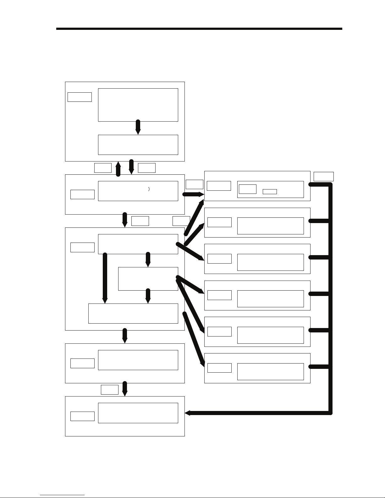
6 Programming Features
73
Digital Operator Displays during Autotuning
Function indicators on the Digital Operator change during autotuning as
in the following diagram.
PRGM
TUn
DSPLDSPL
E03
STOP
TUn
RUN
E12
STOP
E04
E09
E05
End
XXX
FREF
DSPL
RESET
STOP
Function
Indicators
Lit
Set constants required for autotuning.
• Maximum Voltage
• Maximum Voltage Frequency
• Motor Rated Current
• Motor Rated Slip
Set Autotuning Selection.
• Rotational / Resistance-only
stationary
Digital Operator Display
Lit
Autotuning mode
(Waiting for RUN input
• Set constants for tuning.
Digital Operator Display
Flashing
Resistance tuning
• DC voltage (20%, 40%, 60%)
applied.
Resistance-only
stationary
Rotational
No-load Current Tuning
• Acceleration
• Tuning
• Deceleration
• Return constants set for tuning to their
original values.
• Write tuned constants.
Digital Operator Display
Lit
Autotuning completed.
Function
Indicators
Lit
Frequency reference setting /
monitor
Digital Operator
Display
Lit
Cancelled because
of STOP key
Digital Operator
Display
Lit
Cancelled because of current
detection error.
Digital Operator
Display
Lit
Cancelled because of
resistance error.
Digital Operator
Display
Lit
Cancelled because of
acceleration error.
Digital Operator
Display
Lit
Cancelled because of no-load
current error.
Digital Operator
Display
Lit
Cancelled because of
normally detected error.
Page 75
74
Reverse Run Prohibit (n006)
The Reverse Run Prohibit setting disables accepting a Reverse Run
Command from the control circuit terminal or Digital Operator. This
setting is used for applications where a Reverse Run Command can
cause problems.
Multi-step Speed Selection
Up to 17 speed steps (including Jog frequency reference) can be set
using the following combinations of frequency reference and input terminal selections.
Setting Description
0 Reverse run enabled.
1 Reverse run disabled.
8-step speed change
n003=1 (Operation mode selection)
n004=1 (Frequency reference selection)
n024=25.0 Hz (Frequency reference 1)
n025=30.0 Hz (Frequency reference 2)
n026=35.0 Hz (Frequency reference 3)
n027=40.0 Hz (Frequency reference 4)
n028=45.0 Hz (Frequency reference 5)
n029=50.0 Hz (Frequency reference 6)
n030=55.0 Hz (Frequency reference 7)
n031=60.0 Hz (Frequency reference 8)
n054=6 (Multi-function contact input terminal S5)
n055=7 (Multi-function contact input terminal S6)
n056=8 (Multi-function contact input terminal S7)
n053=1
When all multi-function
reference inputs are OFF, the
frequency reference selected
by constant n004 (Frequency
Reference Selection) becomes
effective.
NOTE
S1
S2
S5
S6
S7
S3
S4
SC
FWD
Run/Stop
REV Run/Stop
External Fault
Fault Reset
Multi-step
Speed Ref 1
Multi-step
Speed Ref 2
Multi-step
Speed Ref 3
* For more information on how to
select the sequence voltage and the
current input, refer to page 226.
Page 76
6 Programming Features
75
n050 = 1 (Input terminal S1) (factory setting)
n051 = 2 (Input terminal S2) (factory setting)
n052 = 3 (Input terminal S3) (factory setting)
n053 = 5 (Input terminal S4) (factory setting)
n054 = 6 (Input terminal S5) (factory setting)
n055 = 7 (Input terminal S6) (factory setting)
n056 = 8 (Input terminal S7) (Change the setting to 8.)
16-step speed operation
Set frequency references 9 to 16 for n120 to n127.
Set the input terminal for a multi-step speed reference using the multifunction input selection.
Operating at Low Speed
By inputting a Jog Command and then a Forward (Reverse) Run Command, operation is enabled at the jog frequency set in n032. When
multi-step speed references 1, 2, 3 or 4 are input simultaneously with
the Jog Command, the Jog Command has priority.
Constant No. Name Setting
n032 Jog Frequency Factory setting: 6.00 Hz
n050 to n056 Jog References Set to 10 for any constant.
Frequency
reference
FWD (REV) Run/Stop
Multi-step speed ref. 1
(terminal S5)
Multi-step speed ref. 2
(terminal S6)
Multi-step speed ref. 3
(terminal S7)
Time
(n024) 25.0 Hz
(n025) 30.0 Hz
(n026) 35.0 Hz
(n027) 40.0 Hz
(n028) 45.0 Hz
(n029) 50.0 Hz
(n030) 55.0 Hz
(n031) 60.0 Hz
Page 77
76
Adjusting Speed Setting Signal
The relationship between the analog inputs and the frequency reference
can be set to provide the frequency reference as analog inputs to control
circuit terminal FR or FC.
1. Analog Frequency Reference Gain (n060)
The frequency reference provided when the analog input is 10 V (or
20 mA) can be set in units of 1%. (Max. Output Frequency
n011=100%)
* Factory setting: 100%
2. Analog Frequency Reference Bias (n061)
The frequency reference provided when the analog input is 0 V
(4 mA or 0 mA) can be set in units of 1%. (Max. Output Frequency
n011=100%)
* Factory setting: 0%
Typical Settings
• To operate the Inverter with a frequency reference of 0% to 100%
at an input voltage of 0 to 5 V
Frequency Reference
Max. Output Frequency X GAIN
100
0 V
(4 mA)
(0 mA)
10 V
(20 mA)
(20 mA)
( ) indicates the value when a current
reference input is selected
Max. Output Frequency X BIAS
100
Max. frequency (100%)
Gain n060 = 200
Bias n061 = 0
Page 78
6 Programming Features
77
• To operate the Inverter with a frequency reference of 50% to
100% at an input voltage of 0 to 10 V
Adjusting Frequency Upper and Lower Limits
• Frequency Reference Upper Limit (n033)
Sets the upper limit of the frequency reference in units of 1%.
(n011: Max. Output Frequency = 100%)
Factory setting: 100%
• Frequency Reference Lower Limit (n034)
Sets the lower limit of the frequency reference in units of 1%.
(n011: Max. Output Frequency = 100%)
When operating at a frequency reference of 0, operation is continued
at the frequency reference lower limit.
However, if the frequency reference lower limit is set to less than the
Minimum Output Frequency (n016), operation is not performed.
Factory setting: 0%
Using Four Acceleration/Deceleration Times
* When deceleration to a stop is selected (n005 = 0).
Max. frequency (100%)
Gain n060 = 100
Bias n061 = 50
0 V 10 V
Internal
frequency
reference
Frequency
Upper Limit
(n033)
Frequency
Lower Limit
(n034)
Set frequency reference
Forward (Reverse)
Run Command
Multi-Step
Speed Reference
Accel/Decel
Time Selection 1
Accel/Decel
Time Selection 2
Output
Frequency
Accel
Time 2
(n021)
Accel
Time 1
(n019)
Decel
Time 2
(n022)
Time
ON
ON
ON
ON
ON
Decel
Time 1
(n020)
Accel
Time 3
(n041)
Accel
Time 4
(n043)
Decel
Time 4*
(n044)
Decel
Time 3*
(n042)
Page 79
78
By setting a multi-function input selection (any one of n050 to n056) to
11 (acceleration/deceleration time selection 1) or 27 (acceleration/
deceleration time selection 2), the acceleration/deceleration time is
selected by ON/OFF combinations of acceleration/deceleration time
selection 1 and acceleration/deceleration time selection 2 (terminals S1
to S7).
The combinations of acceleration/deceleration time selection settings
are shown below.
Accleration/
Deceleration
Time Selection 1
Accleration/
Deceleration
Time Selection 2
Acceleration Time Deceleration Time
OFF OFF Acceleration time 1
(n019)
Deceleration time 1
(n020)
ON OFF Acceleration time 2
(n021)
Deceleration time 2
(n022)
OFF ON Acceleration time 3
(n041)
Deceleration time 3
(n042)
ON ON Acceleration time 4
(n043)
Deceleration time 4
(n044)
No. Name Unit Setting Range Factory
Setting
n019 Acceleration Time 1 Depends on
n018 setting.
(See the next
table.)
Depends on
n018 setting.
(See the next
table.)
10.0 s
n020 Deceleration Time 1 10.0 s
n021 Acceleration Time 2 10.0 s
n022 Deceleration Time 2 10.0 s
n041 Acceleration Time 3 10.0 s
n042 Deceleration Time 3 10.0 s
n043 Acceleration Time 4 10.0 s
n044 Deceleration Time 4 10.0 s
Page 80
6 Programming Features
79
n018 Settings
Note: Constant n018 can be set while stopped.
If a value exceeding 600.0 s is set for the acceleration/deceleration time
when n018=0 (in units of 0.1 s), 1 cannot be set for n018.
• Acceleration time
Set the time needed for the output frequency to reach 100% from 0%.
• Deceleration time
Set the time needed for the output frequency to reach 0% from 100%.
(Max. Output Frequency n011 = 100%)
Momentary Power Loss Ridethrough Method (n081)
When continuous operation after power recovery is
selected, stand clear of the Inverter or the load. The
Inverter may restart suddenly after stopping.
(Construct the system to ensure safety, even if the
Inverter should restart.) Failure to observe this warning may result in injury.
When constant n081 is set to 1 or 2, operation automatically restarts
even if a momentary power loss occurs.
No. Unit Setting Range
n018 0 0.1 s 0.0 to 999.9 s (999.9 s or less)
1 s 1000 to 6000 s (1000 s or more)
1 0.01 s 0.00 to 99.99 s (99.99 s or less)
0.1 s 100.0 to 600.0 s (100 s or more)
Setting
*3
Description
0
Continuous operation after momentary power
loss not enabled.
1
*1
Continuous operation after power recovery
within momentary power loss ridethrough time
0.5 s
2
*1, *2
Continuous operation after power recovery
(Fault output not produced.)
WARNING
Page 81
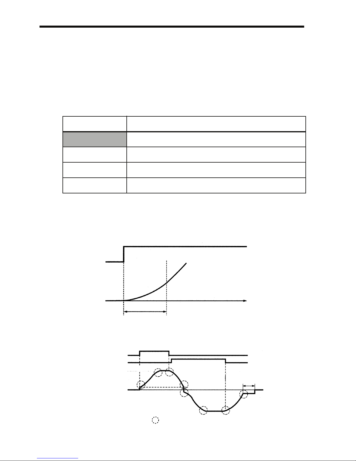
80
* 1. Hold the operation signal to continue operation after recovery from a
momentary power loss.
* 2. When 2 is selected, the Inverter restarts if power supply voltage recovers
while the control power supply is held.
No fault signal is output.
S-curve Selection (n023)
To prevent shock when starting and stopping the machine, acceleration/
deceleration can be performed using an S-curve pattern.
Note: 1. S-curve characteristics are not supported for simple positioning con-
trol, so use a set value of 0.
2. The S-curve characteristic time is the time from acceleration/deceleration rate 0 to the normal acceleration/deceleration rate determined by
the set acceleration/deceleration time.
The following time chart shows switching between FWD/REV run
when decelerating to a stop.
Setting S-curve Selection
0 S-curve characteristic not provided.
1 0.2 s
2 0.5 s
3 1.0 s
Frequency
Reference
Output
Frequency
Time
S-curve Characteristic Time (Ts)
Output
Frequency
Forward Run Command
Reverse Run Command
Acceleration
Output Frequency
Min. Output
Frequency n016
S-curve Characteristics in
Acceleration
Deceleration
DC Injection Braking
Time at Stop
n090
Deceleration
Min. Output Frequency
n016
Page 82
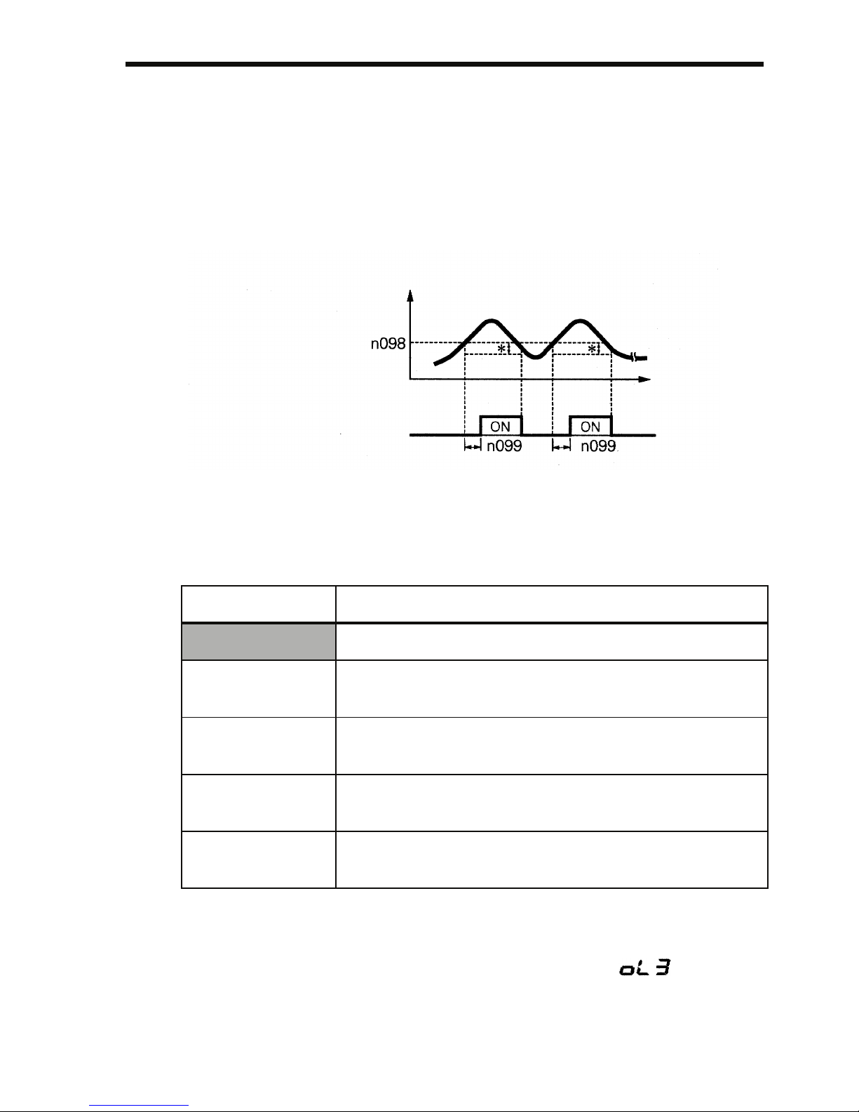
6 Programming Features
81
Torque Detection
If an excessive load is applied to the machine, an increase in the output
current can be detected to output an alarm signal to multi-function output terminal MA, MB, P1, or P2.
To output an overtorque detection signal, set one of the output terminal
function selections n057 to n059 for overtorque detection (Setting: 6
(NO contact) or 7 (NC contact)).
* The overtorque detection release width (hysteresis) is set at approx. 5% of
the Inverter rated current.
Overtorque Detection Function Selection 1 (n096)
1. To detect overtorque during acceleration/deceleration, set n096 to 3 or 4.
2. To continue operation after overtorque detection, set n096 to 1 or 3.
During detection, the Digital Operator will display an alarm
(flashing).
3. To stop the Inverter and generate a fault at overtorque detection, set n096
Setting Description
0 Overtorque detection not provided.
1 Detected during constant-speed running. Oper-
ation continues after detection.
2 Detected during constant-speed running. Oper-
ation stops during detection.
3 Detected during running. Operation continues
after detection.
4 Detected during running. Operation stops dur-
ing detection.
Motor Current
Multi-function Output Signal
(Overtorque Detection Signal)
Terminal MA, MB, P1, or P2
Time
Page 83

82
to 2 or 4. At detection, the Digital Operator will display an fault
(ON).
Overtorque Detection Level (n098)
Set the overtorque detection current level in units of 1%. (Inverter rated
current = 100%) When detection by torque is selected, the motor rated
torque becomes 100%.
Factory setting: 160%
Overtorque Detection Time (n099)
If the time that the motor current exceeds the Overtorque Detection
Level (n098) is longer than Overtorque Detection Time (n099), the
overtorque detection function will operate.
Factory setting: 0.1 s
Overtorque/Undertorque Detection Function Selection 2
(n097)
When vector control mode is selected, overtorque/undertorque detection can be performed either by detecting the output current or the output torque.
When V/f control mode is selected, the setting of n097 is invalid, and
overtorque/undertorque is detected by the output current.
Frequency Detection Level (n095)
Effective when one or more of the Multi-function Output Selections
n057, n058 and n059 are set for frequency detection (setting: 4 or 5).
Frequency detection turns ON when the output frequency is higher or
lower than the setting for the Frequency Detection Level (n095).
Frequency Detection 1
Output frequency ≥ Frequency Detection Level n095
Setting Description
0 Detected by output torque
1 Detected by output current
Page 84
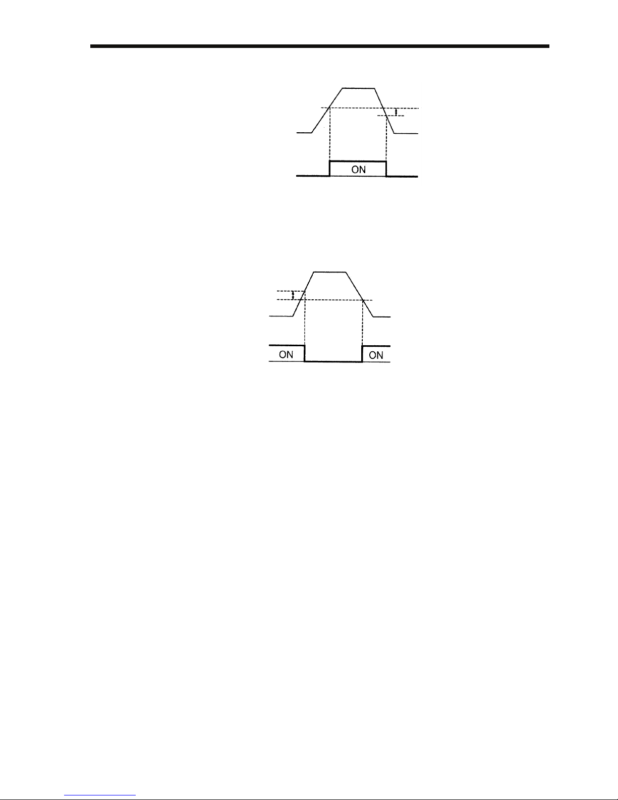
6 Programming Features
83
(Set n057, n058 or n059 to 4.)
Frequency Detection 2
Output frequency ≤ Frequency Detection Level n095
(Set n057, n058 or n059 to 5.)
Frequency Detection
Level [Hz] (n095)
Output
Frequency
Frequency
Detection
Signal
Release
Width
−2Hz
Release
Width
+2Hz
Frequency
Detection
Level (Hz)
(n095)
Output
Frequency
Frequency
Detection
Signal
Page 85
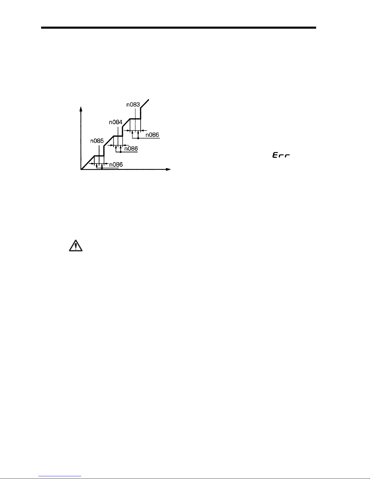
84
Jump Frequencies (n083 to n086)
This function allows the prohibition or “jumping” of critical frequencies
so that the motor can operate without resonance caused by the machine
system. This function is also used for dead band control. Setting the values to 0.00 Hz disables this function.
Set prohibited frequencies 1, 2, and 3 as follows:
Operation is prohibited within the jump frequency ranges.
However, the motor will operate without jumping during acceleration/
deceleration.
Continuing Operation Using Automatic Retry Attempts (n082)
When the fault retry function is selected, stand clear of
the Inverter or the load. The Inverter may restart suddenly after stopping.
(Construct the system to ensure safety, even if the
Inverter should restart.) Failure to observe this warning may result in injury.
The Inverter can be set to restart and reset fault detection after a fault
occurs. The number of self-diagnosis and retry attempts can be set to up
to 10 in n082. The Inverter will automatically restart after the following
faults occur:
OC (overcurrent)
OV (overvoltage)
The number of retry attempts is cleared to 0 in the following cases:
1. If no other fault occurs within 10 minutes after retry
2. When the Fault Reset signal is ON after the fault is detected
3. When the power supply is turned OFF
Output Frequency
Frequency Reference
n083 ≥ n084 ≥ n085
If this condition is not satisfied,
the Inverter will display fo
r
one second and restore the
data to initial settings.
WARNING
Page 86

6 Programming Features
85
Frequency Offset Selection (n146)
An offset frequency (which can be set with a constant) can be added to
or subtracted from the frequency reference using multi-function inputs.
Constant
No.
Name Description Factory
Setting
n083 Jump Frequency 1
(Offset Frequency 1)
1st digit of n146 is 0 or 1:
Setting unit: 0.01 Hz
Setting range: 0.00 to
400.0 Hz
1st digit of n146 is 2:
Setting unit: 0.01%
Setting range: 0.00% to
100.0% (Percentage of Maximum Output Frequency)
0.00 Hz
n084 Jump Frequency 2
(Offset Frequency 2)
1st digit of n146 is 0 or 1:
Setting unit: 0.01 Hz
Setting range: 0.00 to
400.0 Hz
1st digit of n146 is 2:
Setting unit: 0.01%
Setting range: 0.00% to
100.0% (Percentage of Maximum Output Frequency)
0.00 Hz
n085 Jump Frequency 3
(Offset Frequency 3)
1st digit of n146 is 0 or 1:
Setting unit: 0.01 Hz
Setting range: 0.00 to
400.0 Hz
1st digit of n146 is 2:
Setting unit: 0.01%
Setting range: 0.00% to
100.0% (Percentage of Maximum Output Frequency)
0.00 Hz
Page 87
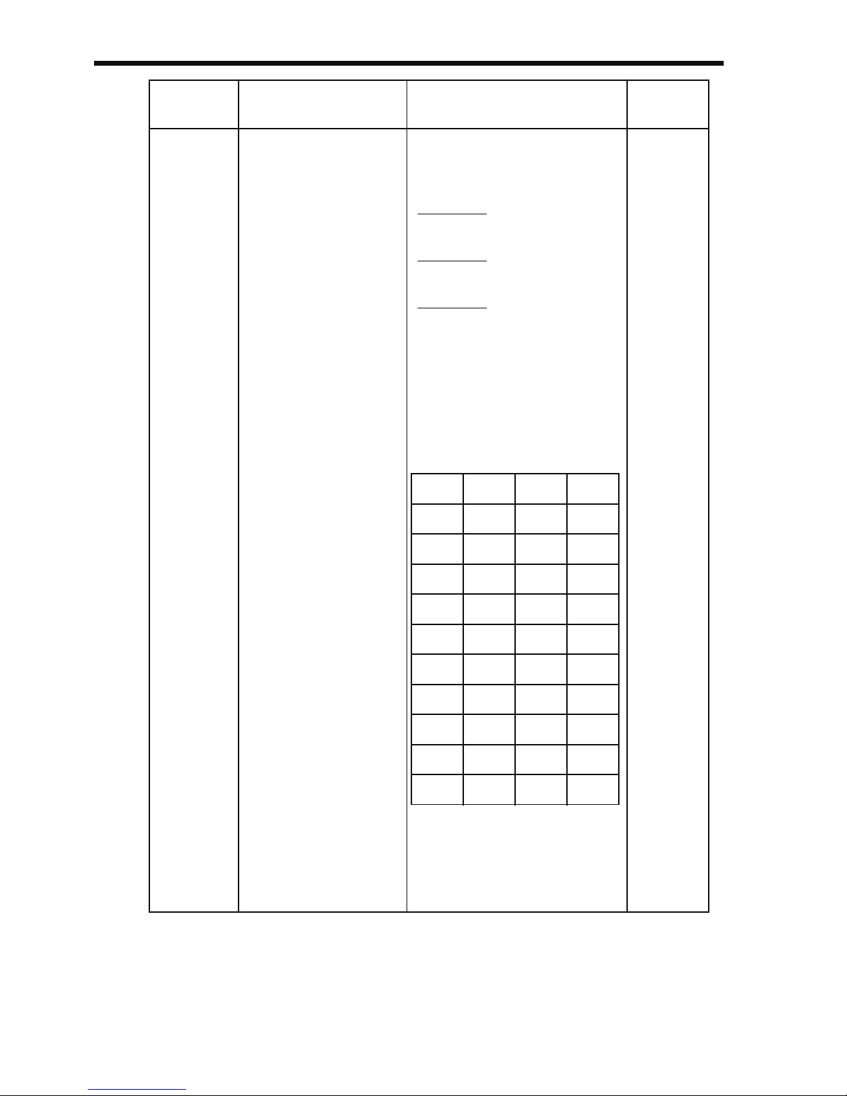
86
• If the 1st digit “x” of Frequency Offset Selection (n146) is 0 (frequency offsets disabled), the set values of constants n083 to n085
will function as jump frequencies.
n146 Frequency Offset Se-
lection
n146 is separated in 2 digits
(n146=xy). The first digit “x”
selects the use of parameters n083 to n085:
n146= 0y:
Disabled (n083 to n085 are
jump frequencies)
n146= 1y:
Enabled (n083 to n085 are
offset frequencies in Hz)
n146= 2y:
Enabled (n083 to n085 are
offset frequencies in percent)
The 2nd digit “y” selects the
sign of the offset frequencies. Refer to the table below
for the possible combinations:
Note: When the 2nd digit of
n146 is changed, the
set values of n083 to
n085 will be initialized
to 0.
0
Constant
No.
Name Description Factory
Setting
y n083 n084 n085
0+++
1 − ++
2+− +
3 −−+
4++−
5 − + −
6+−−
7 −−−
8 −−−
9 −−−
Page 88

6 Programming Features
87
• If the 1st digit “x” of Frequency Offset Selection (n146) is 1 or 2 (frequency offsets enabled), the set values of constants n083 to n085 will
function as frequency offsets.
• In order to activate the offset frequencies 1 to 3 of the Multi-function
Input Selections (n050 to n056) must be programmed to 30, 31 or 33.
Depending on the input status following combinations of the offset
frequencies can be used. Note that the sign specified with “y” is used.
• The enabled offset amount can be monitored on the display of U-12
on the Digital Operator.
Terminal Input Status Final Offset Amount
Offset
Frequency
Input 3
Offset
Frequency
Input 2
Offset
Frequency
Input 1
OFF OFF OFF None
OFF OFF ON n083
OFF ON OFF n084
OFF ON ON n083 + n084
ON OFF OFF n085
ON OFF ON n083 + n085
ON ON OFF n084 + n085
ON ON ON n083 + n084 + n085
Moni-
tor No.
Name Description
U-12 Offset amount 1st digit “x”of n146 = 0: "----" displayed
1st digit “x” of n146 = 1: Display range: −400
to 400.0 Hz
1st digit “x” of n146 = 2: Display range: −
100% to 100.0%
Page 89
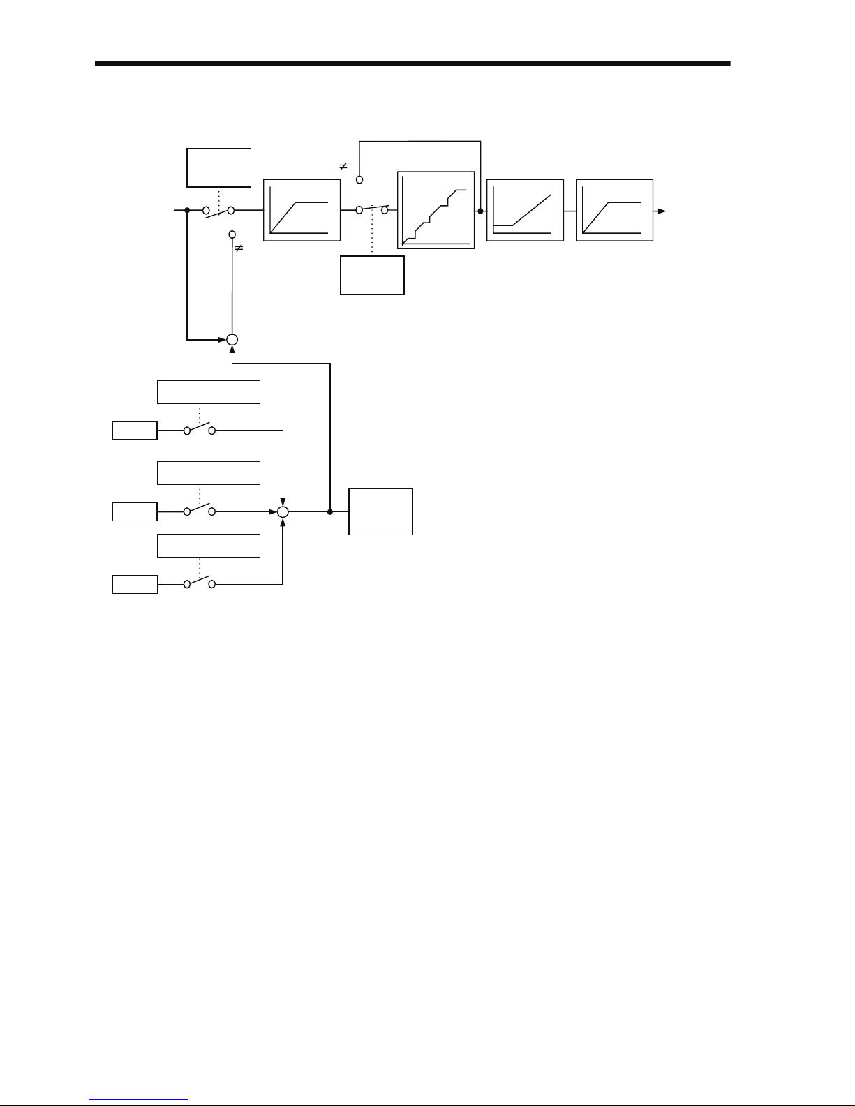
88
The following block diagram illustrates the Frequency Offset Function.
Operating a Coasting Motor without Tripping
To operate a coasting motor without tripping, use the Speed Search
Command or DC Injection Braking at Startup.
Speed Search Command
Restarts a coasting motor without stopping it. This function enables
smooth switching between motor commercial power supply operation
and Inverter operation.
Set a Multi-function Input Selection (n050 to n056) to 14 (Search Command from maximum output frequency) or 15 (Search Command from
set frequency).
Build a sequence so that a FWD (REV) Run Command is input at the
same time as the Search Command or after the Search Command. If the
Run Command is input before the Search Command, the Search Command will be disabled.
00
0
0
n146,
right digit
Selected
Frequency
Reference
n083
n084
n085
Frequency
Reference
Upper Limit
n146,
right digit
Jump Frequencies
n085
n084
n083
Frequency
Reference
Lower Limit
400 Hz
Frequency
Reference
(U-01)
n034 x n011
n033 x n011
Frequency Offset
Input 1
Frequency Offset
Input 2
Frequency Offset
Input 3
Offset
Volume
(U-12)
Page 90
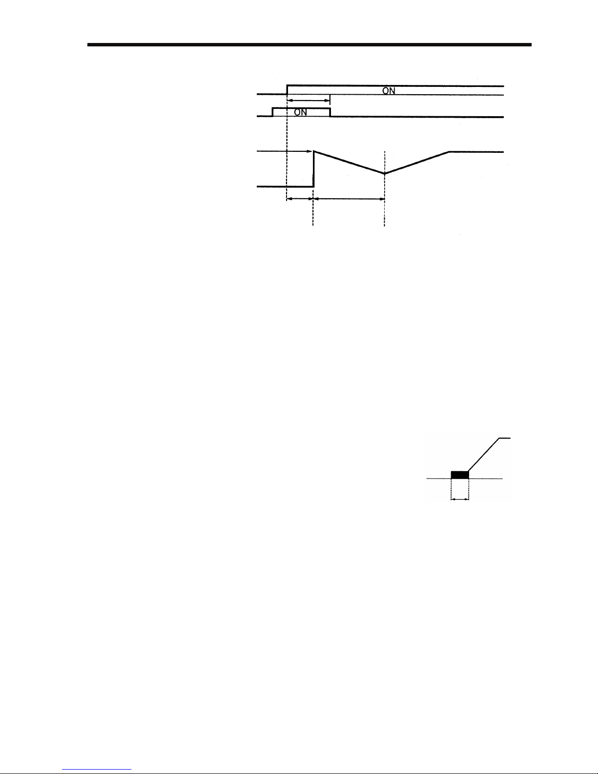
6 Programming Features
89
Time Chart at Search Command Input
The deceleration time for speed search operation can be set in n101.
If the setting is 0, however, an initial value of 2.0 s will be used.
The speed search starts when the Inverter’s output current is greater
than or equal to the speed search operation level (n102).
DC Injection Braking at Startup (n089, n091)
Restarts a coasting motor after stopping it. Set the DC injection braking
time at startup in n091 in units of 0.1 s. Set the DC Injection Braking
Current in n089 in units of 1% (Inverter rated current =100%). When
the setting of n091 is 0, DC injection braking is not performed and
acceleration starts from the minimum output frequency.
When n089 is set to 0, acceleration starts
from the minimum output frequency after
baseblocking for the time set in n091.
Holding Acceleration/Deceleration Temporarily
To hold acceleration or deceleration, input an Acceleration/Deceleration Hold Command. The output frequency is maintained when an
Acceleration/Deceleration Hold Command is input during acceleration
or deceleration.
When the Stop Command is input while an Acceleration/Deceleration
Hold Command is being input, the acceleration/deceleration hold is
released and operation coasts to a stop.
Set a Multi-function Input Selection (n050 to n056) to 16 (acceleration/
deceleration hold).
FWD (REV) Run Command
Search Command
Max. Output Frequency or
Frequency Reference at
Run Command Input
Output Frequency
Min. Baseblock
Time (0.5 s)
Speed
Search
Operation
Speed Agreement
Detection
0.5 s Min.
Min. Output
Frequency
n016
DC Injection Braking
Time at Startup
n091
Page 91

90
Time Chart for Acceleration/Deceleration Hold Command
Input
Note: If a FWD (REV) Run Command is input at the same time as an Acceler-
ation/Deceleration Hold Command, the motor will not operate. However, if the Frequency Reference Lower Limit (n034) is set to a value
greater than or equal to the Min. Output Frequency (n016), the motor
will operate at the Frequency Reference Lower Limit (n034).
External Analog Monitoring(n066)
Selects to output either output frequency or output current to analog output terminals AM-AC for monitoring.
Note: Enabled only when n065 is set to 0 (analog monitor output).
Setting Description
0 Output frequency
1 Output current
2 Main circuit DC voltage
3 Torque monitor
4 Output power
5 Output voltage reference
6 Frequency reference monitor
7 PID Feedback Amount (10 V/Maxi-
mum Output Frequency in n011)
8 Data Output via Communications
(MEMOBUS register No.0007H)
(10 V/1000)
FWD (REV)
Run Command
Acceleration/
Deceleration
Hold Command
Frequency
Reference
Output
Frequency
Frequency
Agree
Signal
Page 92
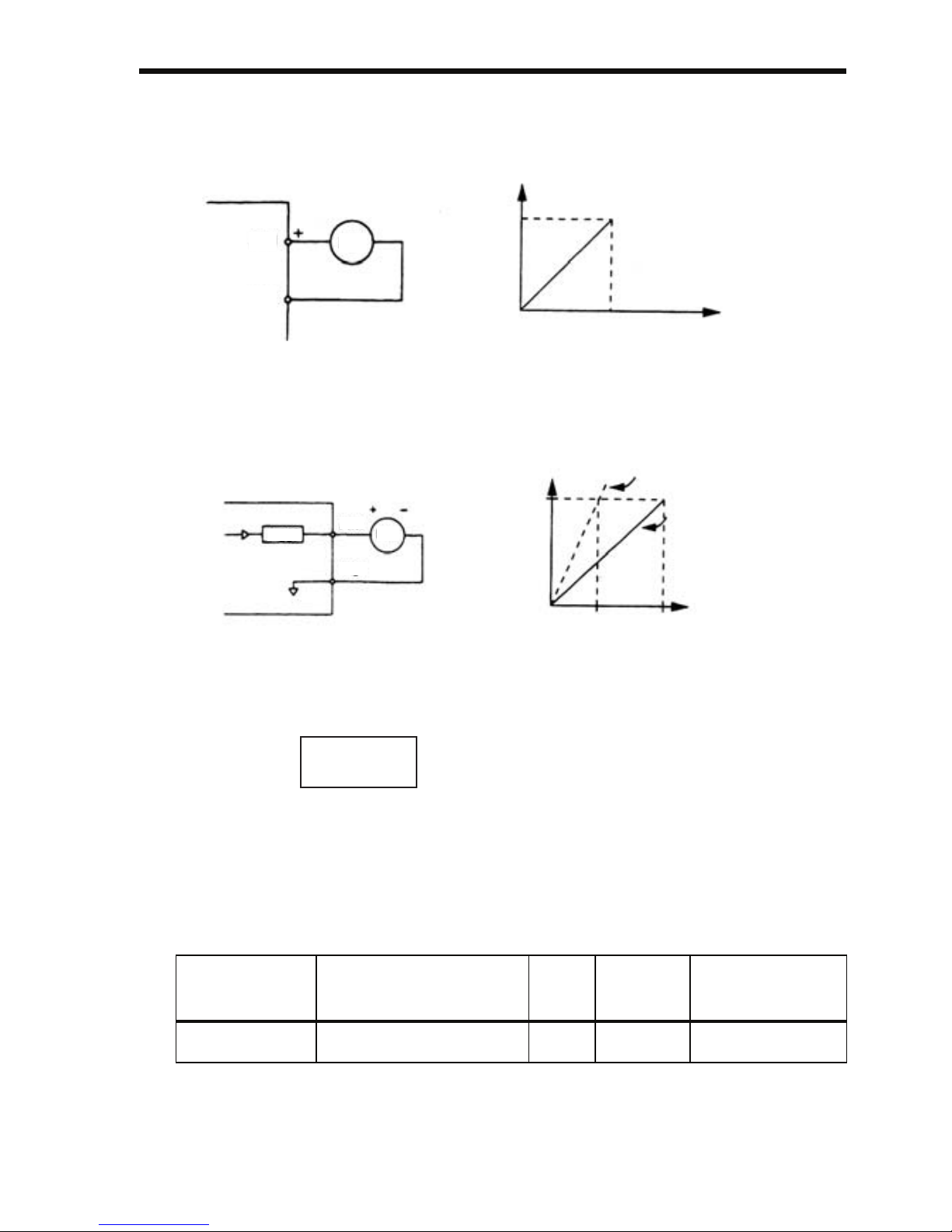
6 Programming Features
91
In factory setting, analog voltage of approx. 10 V is output when output
frequency (output current) is 100 %.
Calibrating Frequency Meter or Ammerter (n067)
Used to adjust analog output gain.
Set the analog output voltage at 100 % of output frequency (output current). Frequency meter displays 0 to 60 Hz at 0 to 3 V.
Using Analog Output (AM-AC) as a Pulse Train Signal
Output (n065)
Analog output AM-AC can be used as a pulse train output (output frequency monitor, frequency reference monitor).
Set n065 to 1 when using pulse train output.
Constant No. Name Unit Setting
range
Factory setting
n065 Monitor Output Type - 0, 1 0
FMAM
AC
100 %
10 V
0
Frequency
Meter
Analog monitor gain
can be set by n067.
Analog Output
Output Frequency
(Output Current)
n067
AM
AC
FM
Frequency Meter/Ammeter
(3 V 1 mA Full-scale)
n067 = 1.00
Factory Setting
n067 = 0.30
100 %
10 V3 V
0
Analog Output
Output Frequency
(Output Current)
10 V ×
n067 setting
0.30
= 3 V
Output frequency becomes
100 % at this value.
Page 93

92
n065 Setting
Pulse train signal can be selected by setting in n150.
Note: Enabled only when n065 is set to 1 (pulse monitor output).
n065 Setting Description
0 Analog monitor output
1 Pulse monitor output
(Output frequency monitor)
n150 Setting Description
0 Output
frequency
monitor
1440 Hz/Max. frequency (n011)
1 1F: Output frequency × 1
6 6F: Output frequency × 6
12 12F: Output frequency × 12
24 24F: Output frequency × 24
36 36F: Output frequency × 36
40 Frequency
reference
monitor
1440 Hz/Max. frequency (n011)
41 1F: Output frequency × 1
42 6F: Output frequency × 6
43 12F: Output frequency × 12
44 24F: Output frequency × 24
45 36F: Output frequency × 36
50 Data Output
via Communications
0 to 14,400 Hz output (MEMOBUS register No.000AH) (1 Hz/
1)
Page 94
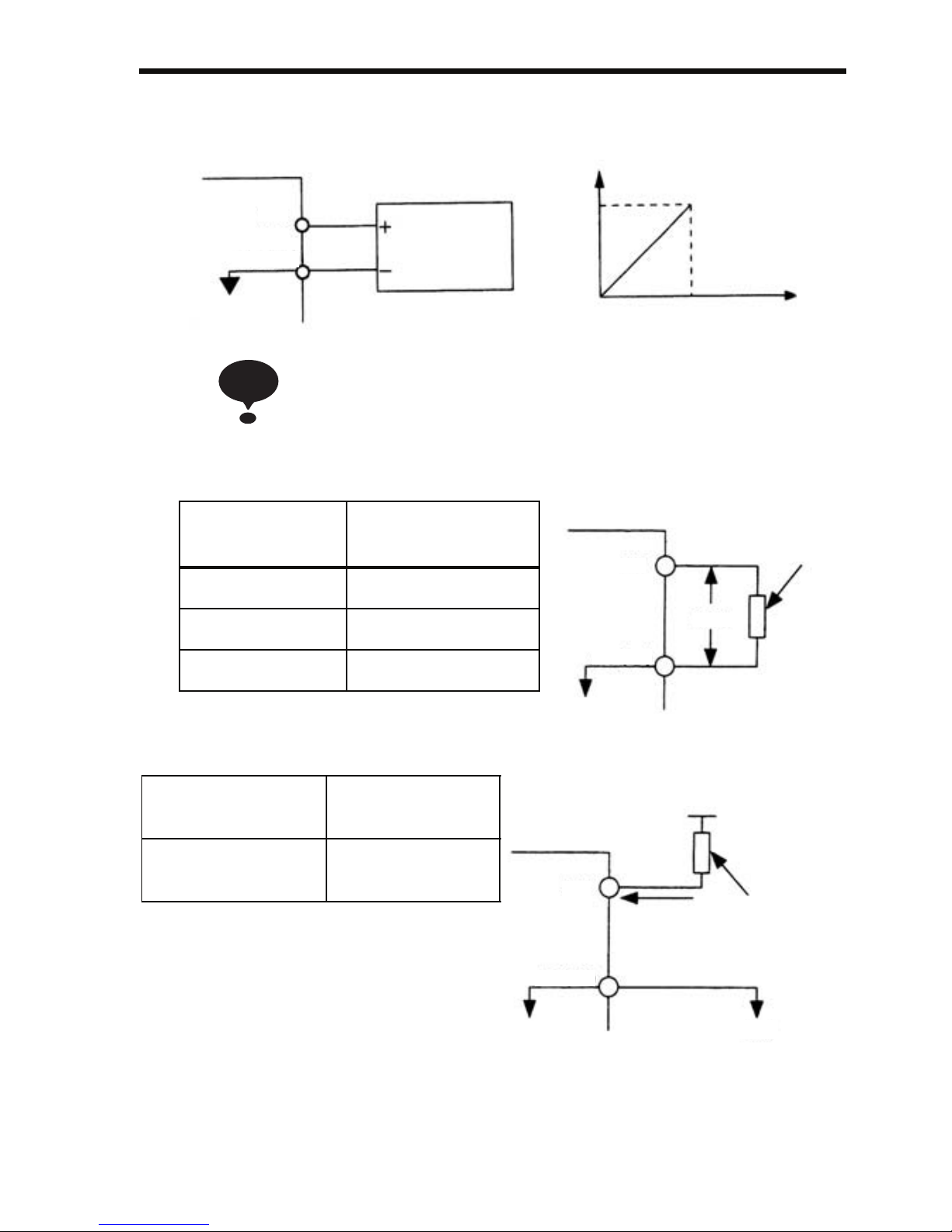
6 Programming Features
93
At the factory setting, the pulse of 1440 Hz can be output when output
frequency is 100 %.
Peripheral devices must be connected according to the following load conditions when using pulse monitor output.
The machine might be damaged when the conditions are not
satisfied.
Used as a Sourcing Output
Used as a Sinking Input
Output Voltage
VRL (V)
Load Impedance
(kΩ)
+5 V 1.5 kΩ or more
+8 V 3.5 kΩ or more
+10 V 10 kΩ or more
External Power
Supply (V)
+12 VDC ±5 %
or less
Sinking Current
(mA)
16 mA or less
Pulse Monitor Output
Pulse
Output Frequency
1440 Hz
100 %
AM
AC (0 V)
NOTE
VRL
AM
AC (0 V)
Load
Impedance
Sink Current
AM
AC (0 V)
(0 V)
External Power Supply
Load
Impedance
Page 95
94
Carrier Frequency Selection (n080)14kHz max
Set the Inverter output transistor switching frequency (carrier frequency).
Note: When the carrier frequency has been set to 14 kHz, use a MEMOBUS
baud rate of 4,800 bps or lower.
Setting Carrier Frequency (kHz) Metallic
Noise from
Motor
Noise and
Current
Leakage
7 12 fout (Hz)
8 24 fout (Hz)
9 36 fout (Hz)
1 2.5 (kHz)
2 5.0 (kHz)
3 7.5 (kHz)
4 10.0 (kHz)
12 14 (kHz)
Higher
Not
audible
Larger
Smaller
Page 96
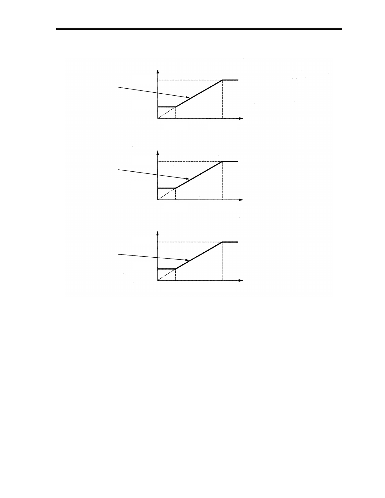
6 Programming Features
95
If the set value is 7, 8, or 9, the carrier frequency will be multiplied by
the same factor as the output frequency.
fc=12 fout
fc=24 fout
fc=36 fout
fout=Output Frequency
fout=Output Frequency
fout=Output Frequency
fc=Carrier Frequency
fc=Carrier Frequency
fc=Carrier Frequency
n080=7
n080=8
n080=9
2.5 kHz
1.0 kHz
2.5 kHz
1.0 kHz
83.3 Hz 208.3 Hz
41.6 Hz 104.1 Hz
2.5 kHz
1.0 kHz
27.7 Hz 69.4 Hz
Page 97

96
The factory setting depends on the Inverter capacity (kVA).
* Reduction of the current is not necessary.
Voltage
Class (V)
Capacity
(kW)
Factory Setting Maximum
Continuous
Output
Current (A)
Reduced
Current
(A)
Continu-
ous Output
Current
(Reduction
Output
Current)
(A)
Setting Carrier
Frequency
(kHz)
FC =
14 kHz
200 V Sin-
gle-phase
or 3-phase
0.1 4 10 0.8
-
0.7 (88%)
0.25 4 10 1.6 1.4 (88%)
0.55 4 10 3.0 2.6 (87%)
1.1 4 10 5.0 4.3 (86%)
1.5 3 7.5 8.0 7.0 6.0 (75%)
2.2 3 7.5 11.0 10.0 8.6 (78%)
4.0 3 7.5 17.5 16.5 14.0 (80%)
5.5 3 7.5 25 23 18.0 (72%)
7.5 3 7.5 33 30 22.1 (67%)
400 V
3-phase
0.37 3 7.5 1.2 1.0 0.8 (67%)
0.55 3 7.5 1.8 1.6 1.28 (71%)
1.1 3 7.5 3.4 3.0 2.2 (65%)
1.5 3 7.5 4.8 4.0 3.2 (67%)
2.2 3 7.5 5.5 4.8 3.84 (70%)
3.0 3 7.5 7.2 6.3 4.9 (68%)
4.0 3 7.5 9.2 8.1 6.4 (74%)
5.5 3 7.5 14.8 * 12.0 (81%)
7.5 3 7.5 18 17 13.0 (72%)
Page 98

6 Programming Features
97
1. Reduce the continuous output current when changing the
carrier frequency to 4 (10 kHz) for 200 V Class (1.5 kW
or more) and 400 V Class Inverters. Refer to the table
above for the reduced current.
Operation Condition
• Input power supply voltage:
3-phase 200 to 230 V (200 V Class)
Single-phase 200 to 240 V (200 V Class)
3-phase 380 to 460 V (400 V Class)
• Ambient temperature:
−10 to 50°C (14 to 122°F)
(Protection structure: open chassis type IP20,
IP00)
−10 to 40°C (14 to 105°F)
(Protection structure: enclosed wall-mounted
type NEMA 1 (TYPE 1))
2. If the wiring distance is long, reduce the Inverter carrier
frequency as described below.
3. Set the Carrier Frequency Selection (n080) to 1, 2, 3, or 4
when using vector control mode. Do not set it to 7, 8, or 9.
4. If the Inverter repeatedly stops and starts with a load
exceeding 120% of the Inverter rated current within a
cycle time of 10 minutes or less, reduce carrier frequency
at a low speed. (Set constant n175 to 1.)
5. The carrier frequency is automatically reduced to 2.5 kHz
when the Reducing Carrier Frequency Selection at Low
Speed (n175) is set to 1 and the following conditions are
satisfied:
Output frequency ≤ 5 Hz
Output current ≥ 110%
Factory setting: 0 (Disabled)
Wiring Distance
between Inverter
and Motor
Up to 50 m Up to 100 m More than 100 m
Carrier Fre-
quency (n080
setting)
10 kHz or less
(n080=1, 2, 3, 4,
7, 8, 9)
5 kHz or less
(n080=1, 2, 7, 8, 9)
2.5 kHz or less
(n080=1, 7, 8, 9)
NOTE
Page 99
98
6. When a carrier frequency of 14 kHz (n080) is selected,
automatic carrier frequency reduction during low-speed
overcurrent is automatically enabled, even if the Reducing
Carrier Frequency Selection at Low Speed (n175) is set to
0 (disabled).
7. When the carrier frequency is set to 14 kHz, the following
functions will be disabled:
• Fast digital input (START/STOP)
• UP 2/DOWN 2
• Motor overheat protection using PTC thermistor input
• Bi-directional PID output
• Frequency offsets
Operator Stop Key Selection (n007)
The Digital Operator stop button can be disabled by a
setting in the Inverter. Install a separate emergency
stop switch.
Failure to observe this warning may result in injury.
Set the processing when the key is pressed during operation
either from a multi-function input terminal or communications.
Setting Description
0 The STOP key is effective either from a multi-
function input terminal or communications. When
the STOP key is pressed, the Inverter stops according to the setting of constant n005. At this
time, the Digital Operator displays a alarm
(flashing). This Stop Command is held in the
Inverter until both Forward and Reverse Run
Commands are open, or until the Run Command
from communications goes to zero.
1 The STOP key is ineffective either from multi-
function input terminals or communications.
Important
WARNING
STOP
Page 100

6 Programming Features
99
Second motor selection
This function switches between two motors for one Inverter. V/f control
must be used for the second motor. Switching is possible from a multifunction input.
The following constants are used as control constants for motor 2.
Note: Not initialized when constants are initialized.
* 1. Upper limit of setting range and factory setting are doubled for 400-V
Class Inverters.
* 2. Depends on Inverter capacity.
Constant
No.
Name Unit Setting Range Factory
Setting
− Control Mode Selec-
tion
− V/f control must be
used.
−
n140 Motor 2 Maximum Out-
put Frequency
0.1 Hz 50.0 to 400.0 Hz 50.0 Hz
n158 Motor 2 Maximum
Voltage
0.1 V
0.1 to 255.0 V
*1
200.0 V
*1
n147 Motor 2 Maximum
Voltage Output Frequency
0.1 Hz 0.2 to 400.0 Hz 50.0 Hz
n159 Motor 2 Middle Output
Frequency Voltage
0.1 V
0.1 to 255.0 V
*1
12.0 V
*1*2
n014 Middle Output
Frequency
0.1 Hz 0.1 to 399.9 Hz 1.3 Hz
n160 Motor 2 Minimum Out-
put Frequency Voltage
0.1 V
0.1 to 50.0 V
*1
12.0 V
*1*2
n161 Motor 2 Rated Current 0.1 A 0.0 to 150% of
Inverter rated cur-
rent
*2
n162 Motor 2 Rated Slip 0.1 Hz 0.0 to 20.0 Hz *2
 Loading...