

Omron CIMR-V7AZ DATASHEET
CIMR-V7AZ
Varispeed V7
Sensorless vector in pocket size
• Nominal torque at 0.5 Hz
• Autotuning
• High carrier up to 14 khz
• Stop accuracy function.
• Integrated PID controller and bidirectional PID-out put
• Motor protection with PTC input
• Pulse input
• Standard digital operator with copy function
• Fieldbus: Modbus, DeviceNet, PROFIBUS, CANopen
• High speed motion bus: ML- II
• Plug-in PLC option unit. Total inverter access.
• CE, UL, and cUL marked
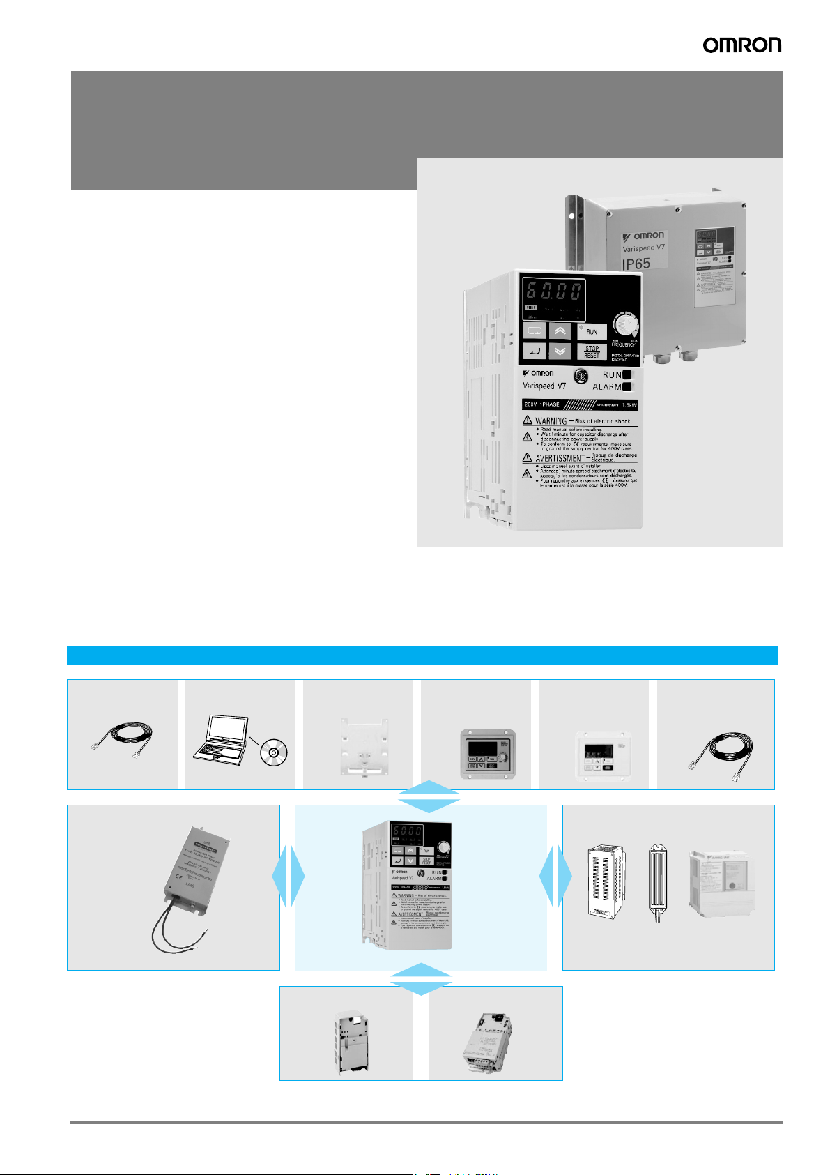
V7 IP65
• Compact size
• Easy wiring
• Built-in filter (Class B)
Customized software*
• The inverter software can be customized to meet
specific application. Examples:
• Traverse sofware S-9381.
*For detailed information please refer to case software section.
Ratings
• 200 V Class single-phase 0.1 to 4 kW
• 200 V Class three-phase 0.1 to 7.5 kW
• 400 V Class three-phase 0.2 to 7.5 kW
System configuration
3G3IV-PCN329-E
Inverter to PC cable
Line filter
* V7 IP65 types are built-in filter inverters.
CX-Drive
*See note
3G3IV-PEZZ8122_
DIN attachment
Communication unit
*See note
JVOP-144
Remote digital oper.
with potentiometer
Varispeed
V7
PLC option unit
JVOP-146
Remote digital oper.
with potentiometer
Braking accessories
LKEB_
*See note
3G3IV-PCN126/326
Digital operator
extension cable
CDBR_B
ERF150WJ_
* Option frames are needed for V7 IP65 type.
329Varispeed V7
Specifications
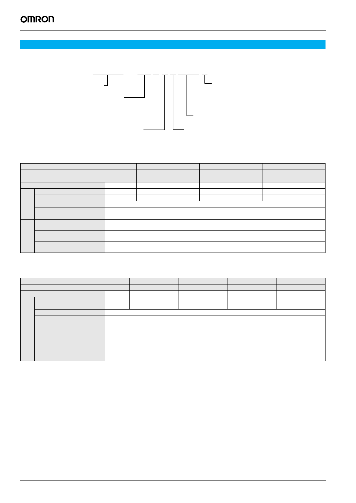
Type designation
CIMR—V7AZB0P10
Inverter
V7 series
A: With digital operator (with potentiometer)
T: V7 IP65 type with digital operator
( without potentiometer )
Z: European standard specifications
Voltage
B: Single-phase 200 VAC
2: Three-phase 200 VAC
4: Three-phase 400 VAC
Protective enclosure:
0: IP20
1: NEMA1
05: IP65
Max. applicable motor output
0P1: 0.1 kW
~
7P5: 7.5 kW
"P" indicates a decimal
[ ]
point
200 V class
IP20 single-phase: CIMR-V7AZ B0P1 B0P2 B0P4 B0P7 B1P5 B2P2 B4P0
IP65 single-phase: CIMR-V7TZ --- --- B0P405 B0P705 B1P505 B2P205 ---
IP20 three-phase: CIMR-V7AZ 20P1 20P2 20P4 20P7 21P5 22P2 24P0
Maximum permissible motor output kW
Inverter capacity kVA
Rated output current A
Output
characteristics
Power
supply
1. Based on a standard 4-pole motor for maximum applicable motor output. Select the inverter model within the allowable motor rated current
Max. output voltage
Max. output frequency
Rated input voltage
and frequency
Allowable voltage
fluctuation
Allowable frequency
fluctuation
1
0.12 0.25 0.55 1.1 1.5 2.2 4.0
0.3 0.6 1.1 1.9 3.0 4.2 6.7
0.8 1.6 3.0 5.0 8.0 11.0 17.5
Proportional to input voltage: 0..240 V
400 Hz
Single-phase 200..240 V 50/60 Hz
3-phase 200..230 V 50/60 Hz
-15%..+10%
+5%
400 V class
IP20 three-phase: CIMR-V7AZ
IP65 three-phase: CIMR-V7TZ
Maximum permissible motor output kW
Inverter capacity kVA
Rated output current A
Output
characteristics
Power
supply
1. Based on a standard 4-pole motor for maximum applicable motor output. Select the inverter model within the allowable motor rated current
Max. output voltage
Max. output frequency
Rated input voltage
and frequency
Allowable voltage
fluctuation
Allowable frequency
fluctuation
40P2 40P4 40P7 41P5 42P2 43P0 44P0 45P5 47P5
1
0.37 0.55 1.1 1.5 2.2 3.0 4.0 5.5 7.5
0.9 1.4 2.6 3.7 4.2 5.5 7.0 11.0 14.0
1.2 1.8 3.4 4.8 5.5 7.2 9.2 14.8 18.0
40P405 40P705 41P505 42P205 43P005 44P005
Proportional to input voltage: 0..400 V
400 Hz
3-phase 380..460 VAC, 50/60 Hz
-15%..+10%
+5%
330 Frequency inverters
Commom specifications
Model number
CIMR-V7AZ-@
CIMR-V7TZ-@
Control methods
Output frequency range
Frequency tolerance
Resolution of frequency set value
Resolution of output frequency
Overload capability
Frequency set value
Control functions
Braking torque
(short term peak torque)
Continuous braking torque approx. 20% without, 150% with external braking resistor
Binary inputs
Binary outputs
Analogue output
Analogue inputs
Braking/acceleration times
Functionality
Display
Motor overload protection Electronic thermal overload relay
Instantaneous overcurrent Motor coasts to a stop at approx. 250% of inverter rated current
Overload Motor coasts to a stop after 1 minute at 150% of inverter rated output current
Overvoltage Motor coasts to a stop if DC bus voltage exceed 410 V (double for 400 V class)
Undervoltage
Momentary power loss
Cooling fin overheat Protected by electronic circuit
Stall prevention level Individual levels during accel/constant speed. Decel ON/OFF available. During decel enable/disable selectable.
Protection functions
Cooling fan fault Detected by electronic circuit (fan lock detection)
Ground fault Protected by electronic circuit (operation level is approx. 250% of rated output current)
Power charge indication
Degree of protection
Cooling
Ambient temperature
Ambient humidity
Storage temperature
Installation
Ambient conditions
Installation height
Vibration
Following items are selectable: not provided (stop if power loss is 15 ms or longer), continuous operation
RUN lamp stays ON or digital operator LED stays ON until the DC bus voltage becomes 50 V or less.
Stops when DC bus voltage is approx. 200 V or less (double for 400 V class)
Self cooling for 200 V 0.1..0.4 kW (3 or single phase) and for 400 V 0.2..0.75 kW
Sine wave PWM (V/f control, sensorless vector control)
Digital set value: ±0.01% (-10..+50 ºC)
Analogue set value: ±0.5% (25 ±10 ºC)
Digital set value: 0.01 Hz (<100 Hz), 0.1 Hz (>100 Hz)
Analogue set value: 1/1000 of maximum frequency
0..10 V (20 kΩ), 4..20 mA (250 Ω), 0..20 mA (250 Ω)
Pulse train input, frequency setting value (selectable)
1 relay output, 2 freely programmable open collector outputs
1 programmable analogue output (0..10 V)/pulse output
2 analogue inputs, 0..10 V, 4..20 mA, 0..20 mA
Optionally frequency, current or set value
(approx. 160 V or less for single-phase series)
if power loss is approx. 0.5 s or shorter, continuous operation
(Charge LED is provided for 400 V)
Cooling fan for 200 V 0.75 to 7.5 kW and for 400 V 1.5 to 7.5 kW
-20 ºC..+60 ºC (short-term temperature during transportation)
Indoor (no corrosive gas, dust, etc.)
10 to 20 Hz, 9.8 m/s2 max; 20 to 50 Hz, 2 m/s2 max
Specifications
0.1..400 Hz
0.01 Hz
150%/60 s
Up to 200 W 150% or more
550 W to 1.1 kW 100% or more
1.5 kW 50% or more
>1.5 kW 20% or more
7 freely programmable inputs
0.01..6000 s
Error and status LED
IP20, NEMA1, IP65
Open air mounting: -10 ºC..50 ºC
Wall mounting: -10 ºC..40 ºC
95% (without condensation)
Max. 1000 m
Varispeed V7 331
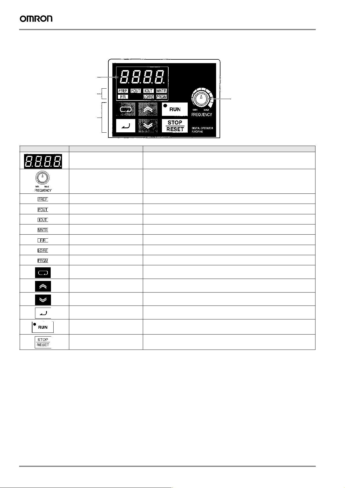
Digital operator
Data display
Indicators
(setting/monitor
item indicators)
Operation keys
FREQUENCY
adjuster
Appearance Name Function
Data display Displays relevant data items, such as frequency reference, output frequency,
Frequency adjuster Sets the frequency reference within a range between 0 Hz and the maximum frequency.
Frequency reference indicator The frequency reference can be monitored or set while this indicator is lit.
Output frequency indicator The output frequency of the inverter can be monitored while this indicator is lit.
Output current indicator The output current of the inverter can be monitored while this indicator is lit.
Multi-function monitor indicator The values set in U01 through U10 are monitored while this indicator is lit.
Forward/reverse selection indicator The direction of rotation can be selected while this indicator is lit when operating the inverter
Local/remote selection indicator The operation of the inverter through the digital operator or according to the set parameters is
Parameter setting indicator The parameters in n001 through n179 can be set or monitored while this indicator is lit.
Mode key Switches the simplified-LED (setting and monitor) item indicators in sequence.
Increment key Increases multi-function monitor numbers, parameter numbers, and parameter set values.
Decrement key Decreases multi-function monitor numbers, parameter numbers, and parameter set values.
Enter key Enters multi-function monitor numbers, parameter numbers, and internal data values after they
RUN key Starts the inverter running when the 3G3MV is in operation with the digital operator
and parameter set values.
with the RUN key.
selectable while this indicator is lit.
Parameter being set will be canceled if this key is pressed before entering the setting.
are set or changed.
2
1
3
STOP/RESET key Stops the inverter unless parameter n007 is set to disable the STOP key.
1. V7 IP65 types have digital operator without frequency adjuster.
2. The status of the local/remote selection indicator can be only monitored while the inverter is in operation. Any RUN comand input is ignored while this
indicator is lit.
3. While inverter is in operation, the parameters can be only monitored and only some parameters can be changed. Any RUN command is ignored while the
parameter setting indicator is lit.
4. For safety reasons, the reset function cannot be used while an operation instruction (forward/reverse) is being input. Turn the operation instruction OFF
before using this function.
Used to reset the inverter when an error occurs.
4
332 Frequency inverters
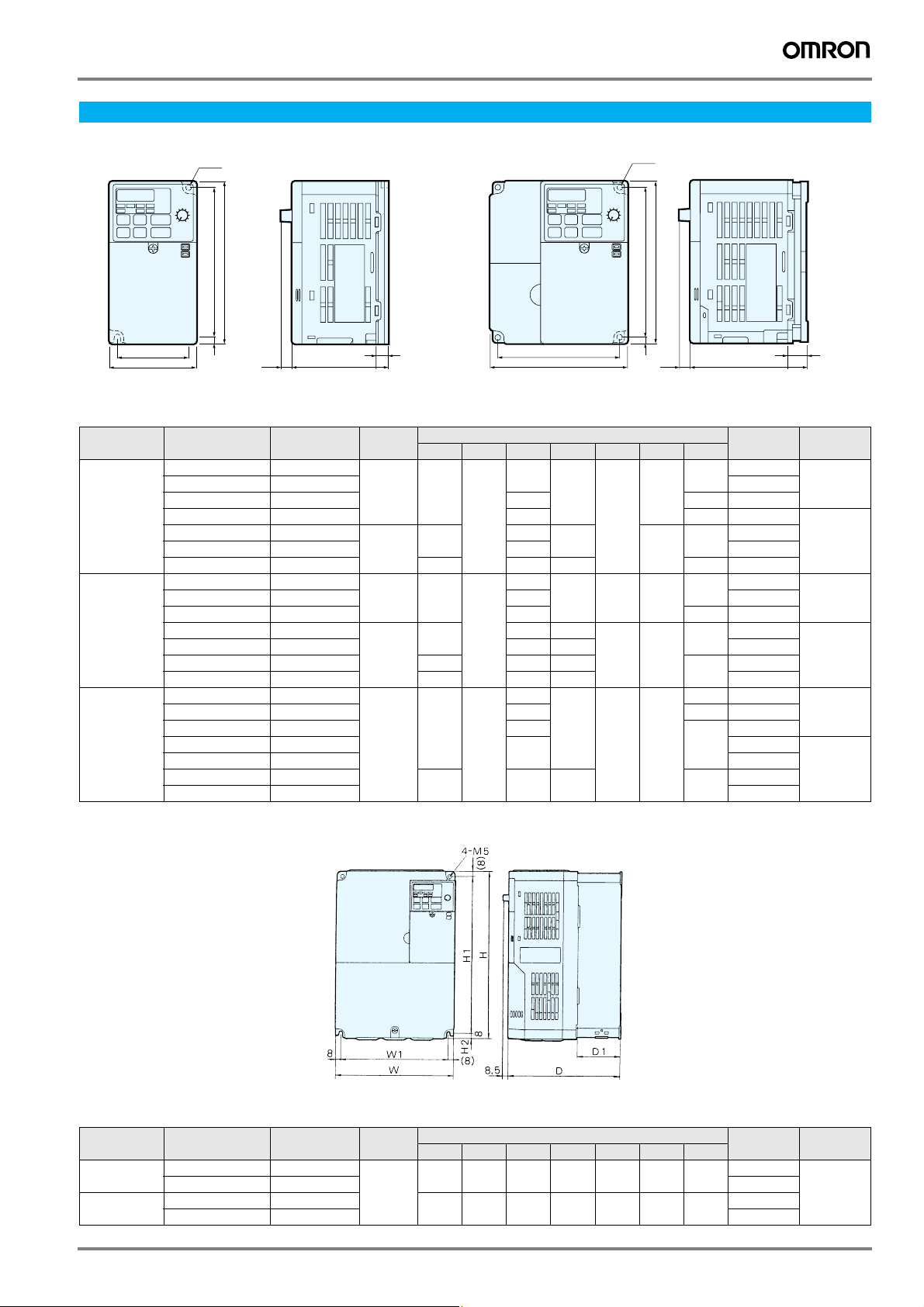
Dimensions
IP 20 type 0.1 to 4 Kw
2 M4
4 M4
Voltage class
Three-phase
200 V
Single-phase
200 V
Three-phase
400 V
W 1
W
Max. applicable
motor output kW
H 2 H 1
H
8.5
(0.34)
D1
D
W 1
W
H 2 H 1
H
(0.34)
8.5
D1
D
Figure 1 Figure 2
Inverter model
CIMR V7AZ
0.12 20P1
0.55 20P4 108 42 0.9
1.1 20P7 128 62 1.1
1.5 21P5
2.2 22P2 140 1.5
4.0 24P0 140 143 128 71 2.1
0.12 B0P1
0.55 B0P4 131 42 1.0
1.1 B0P7
1.5 B1P5 156 96 1.5
2.2 B2P2 140 163 128
4.0 B4P0 170 180 158 2.9
0.37 40P2
1.1 40P7 140
1.5 41P5
2.2 42P2 1.5
3.0 43P0
4.0 44P0 2.1
Figure
168
2
168
2
2
W H D W1 H1 H2 D1
108
108
108
140 143 128 71
128
128
128
Dimensions in mm
76
56
131
140 96
156
96
76
56 118 5
92
96
118
118 5
118 5
5
5
Weight kg
10
64
10
64
71
16 1.0
64
0.6
1.4
0.6
1.5
2.2
1.5
1.5
2.1
Cooling
method
Self cooled0.25 20P2 0.6
Fan cooled
Self cooled0.25 B0P2 76 0.7
Fan cooled
Self cooled0.55 40P4 110 34 1.1
Fan cooled
IP20 / NEMA1 type 5.5/7.5 Kw
Figure 3
Voltage class
Three-phase
200 V
Three-phase
400 V
Max. applicable
motor output kW
5.5 25P5
7.5 27P5 4.8
5.5 45P5
7.5 47P5 4.8
Inverter model
CIMR - V7AZ
Figure
3
W H D W1 H1 H2 D1
180 260 170 164 244 8 65
180 260 170 164 244 8 65
Varispeed V7 333
Dimensions in mm (inches)
Weight kg
4.6
4.8
Cooling
method
Fan cooled
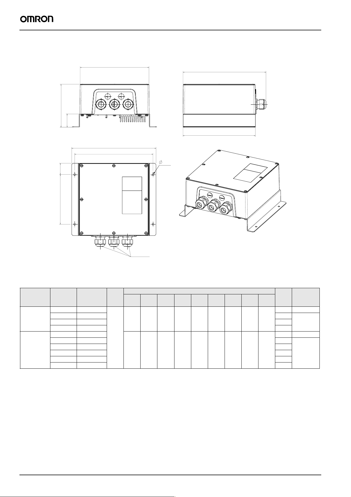
IIP65 type 0.55 to 4 Kw
W 2
D
D1
W
W 1
6 . 4
H 2
H 1
H 1
H
Voltage
class
Single-phase
200 V
Three-phase
400 V
3x PG25
Figure 4
Max.
applicable
motor
output kW
0.55 B0P405
1.1 B0P705 4.3
2.2 B2P205 4.2
0.55 40P405
1.1 40P705 4.3
1.5 41P505 3.7
2.2 42P205 3.7
3.0 43P005 4.1
4.0 44P005 4.1
Inverter
model
CIMR V7TZ
Figure
4
W H D W1 W2 H1 H2 H3 D1
280 240 142 260 228 165 38 275 44
280 240 142 260 228 165 38 275 44
Dimensions in mm
Weight kgCooling
method
3.4 Self cooled
Fan cooled1.5 B1P505 3.7
4.2 Self cooled
Fan cooled
334 Frequency inverters
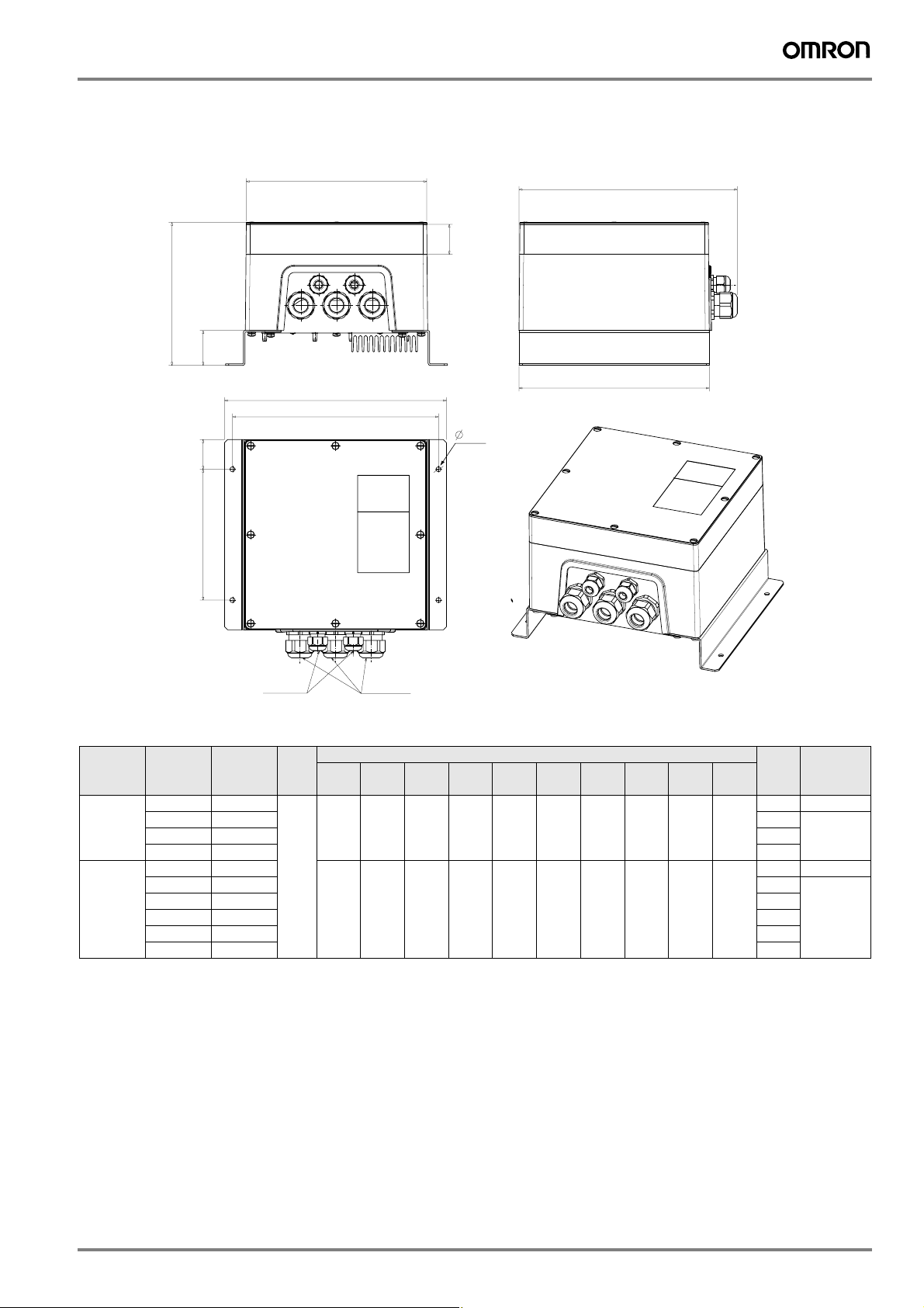
IP65 type 0.55 to 4Kw (with option frame accessory attached)
W 2
D2
D
D1
W
W 1
6 . 4
H 2
H 1
H 1
H
Voltage
class
Single-
phase 200 V
Three-phase
400 V
2x PG12
Max.
applicable
motor
output kW
0.55 B0P405
1.1 B0P705 4.5
2.2 B2P205 4.4
0.55 40P405
1.1 40P705 4.5
1.5 41P505 3.9
2.2 42P205 3.9
3.0 43P005 4.3
4.0 44P005 4.3
Inverter
model
CIMR V7TZ
Figure
280 240 180 260 228 165 38 275 44 38
5
280 240 180 260 228 165 38 275 44 38
3x PG25
W H D W1 W2 H1 H2 H3 D1 D2
Figure 5
Dimensions in mm
Weight kgCooling
method
3.6 Self cooled
Fan cooled1.5 B1P505 3.9
4.4 Self cooled
Fan cooled
Varispeed V7 335
 Loading...